Embed Size (px)
Citation preview

XA1 - Voltage balance relay
2 TB XA1 08.96 E
Contents
1. Applications and features
2. Design
3. Function
4. Operation and settings4.1 Setting of DIP-switches4.2 Setting of the tripping values4.3 Communication via serial interface
adapter XRS1
5. Relay case and technical data5.1 Relay case5.2 Technical data
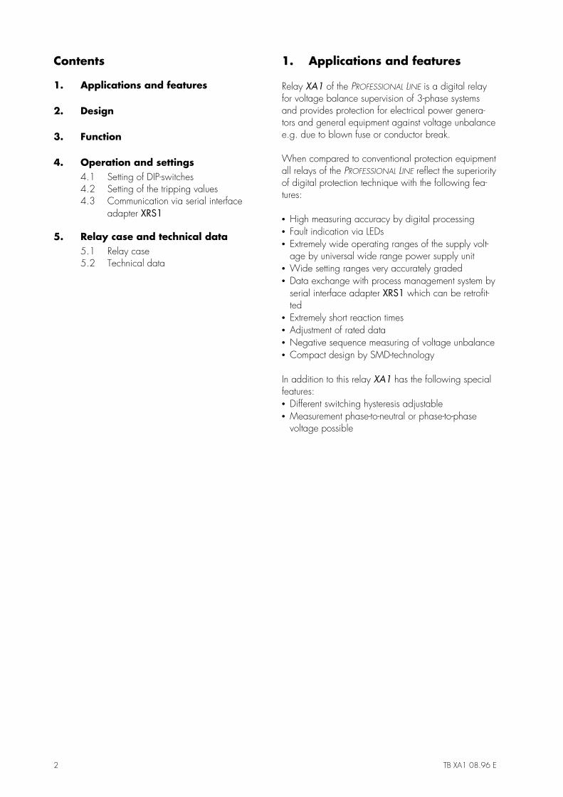
1. Applications and features
Relay XA1 of the PROFESSIONAL LINE is a digital relayfor voltage balance supervision of 3-phase systemsand provides protection for electrical power genera-tors and general equipment against voltage unbalancee.g. due to blown fuse or conductor break.
When compared to conventional protection equipmentall relays of the PROFESSIONAL LINE reflect the superiorityof digital protection technique with the following fea-tures:
• High measuring accuracy by digital processing• Fault indication via LEDs• Extremely wide operating ranges of the supply volt-
age by universal wide range power supply unit• Wide setting ranges very accurately graded• Data exchange with process management system by
serial interface adapter XRS1 which can be retrofit-ted
• Extremely short reaction times• Adjustment of rated data• Negative sequence measuring of voltage unbalance• Compact design by SMD-technology
In addition to this relay XA1 has the following specialfeatures:• Different switching hysteresis adjustable• Measurement phase-to-neutral or phase-to-phase
voltage possible
TB XA1 08.96 E 3
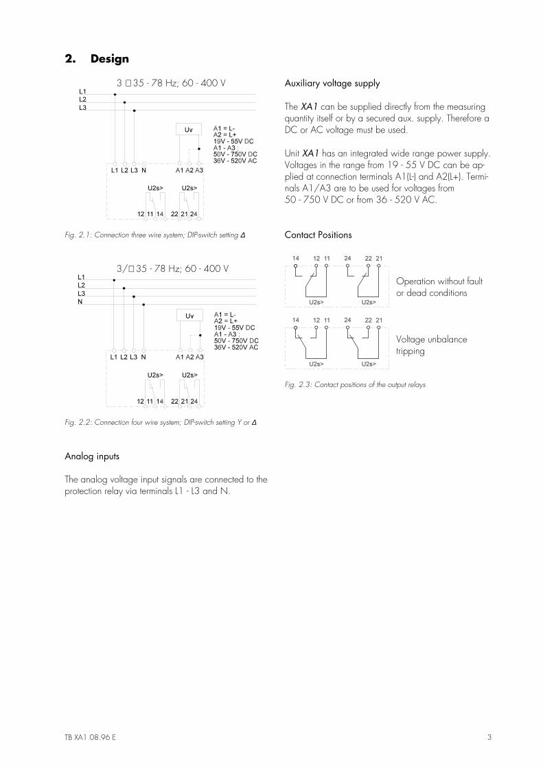
2. Design
3 ∼ 35 - 78 Hz; 60 - 400 V
Fig. 2.1: Connection three wire system; DIP-switch setting ∆
3/∼ 35 - 78 Hz; 60 - 400 V
Fig. 2.2: Connection four wire system; DIP-switch setting Y or ∆
Analog inputs
The analog voltage input signals are connected to theprotection relay via terminals L1 - L3 and N.
Auxiliary voltage supply
The XA1 can be supplied directly from the measuringquantity itself or by a secured aux. supply. Therefore aDC or AC voltage must be used.
Unit XA1 has an integrated wide range power supply.Voltages in the range from 19 - 55 V DC can be ap-plied at connection terminals A1(L-) and A2(L+). Termi-nals A1/A3 are to be used for voltages from50 - 750 V DC or from 36 - 520 V AC.
Contact Positions
Operation without faultor dead conditions
Voltage unbalancetripping
Fig. 2.3: Contact positions of the output relays
4 TB XA1 08.96 E
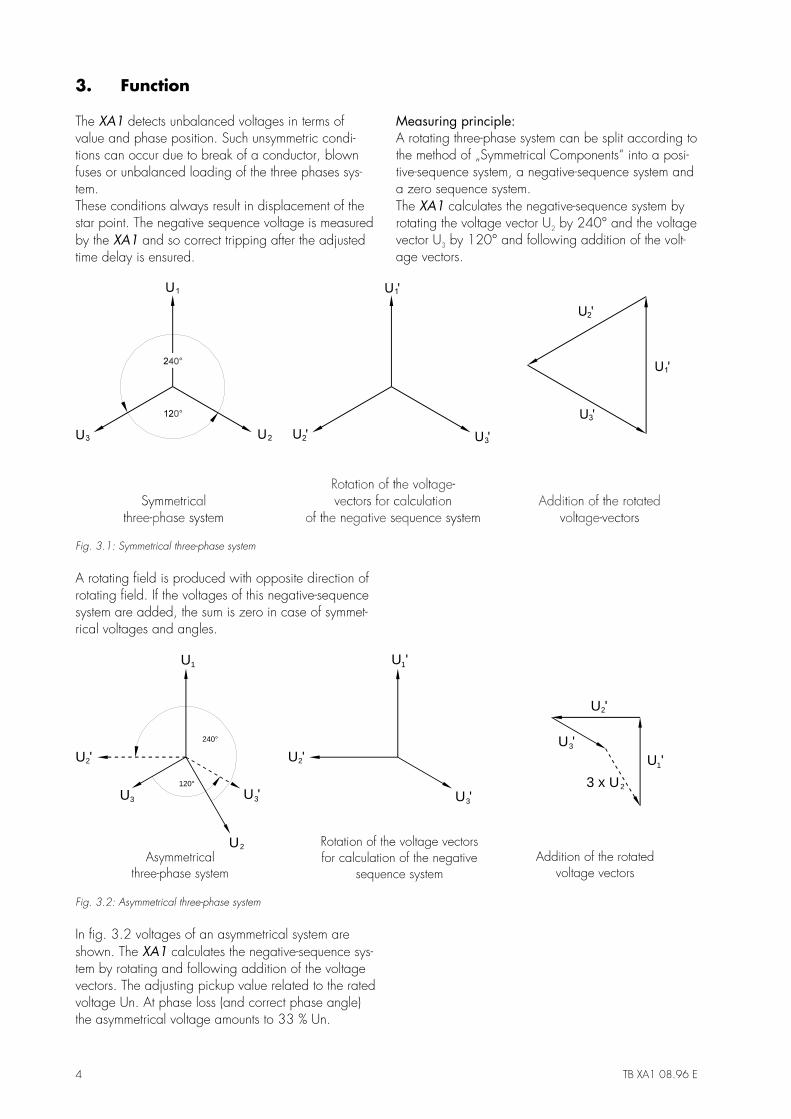
3. Function
The XA1 detects unbalanced voltages in terms ofvalue and phase position. Such unsymmetric condi-tions can occur due to break of a conductor, blownfuses or unbalanced loading of the three phases sys-tem.These conditions always result in displacement of thestar point. The negative sequence voltage is measuredby the XA1 and so correct tripping after the adjustedtime delay is ensured.
Measuring principle:A rotating three-phase system can be split according tothe method of „Symmetrical Components“ into a posi-tive-sequence system, a negative-sequence system anda zero sequence system.The XA1 calculates the negative-sequence system byrotating the voltage vector U2 by 240° and the voltagevector U3 by 120° and following addition of the volt-age vectors.
Fig. 3.1: Symmetrical three-phase system
A rotating field is produced with opposite direction ofrotating field. If the voltages of this negative-sequencesystem are added, the sum is zero in case of symmet-rical voltages and angles.
Rotation of the voltage vectorsfor calculation of the negative
sequence systemAsymmetrical
three-phase systemAddition of the rotated
voltage vectors
U
U
U1 U '1
U '1U '2 U '2
U '2
U '3 U '3
U '3
2
3
23 x U120°
240°
Fig. 3.2: Asymmetrical three-phase system
In fig. 3.2 voltages of an asymmetrical system areshown. The XA1 calculates the negative-sequence sys-tem by rotating and following addition of the voltagevectors. The adjusting pickup value related to the ratedvoltage Un. At phase loss (and correct phase angle)the asymmetrical voltage amounts to 33 % Un.
TB XA1 08.96 E 5
4. Operation and settings
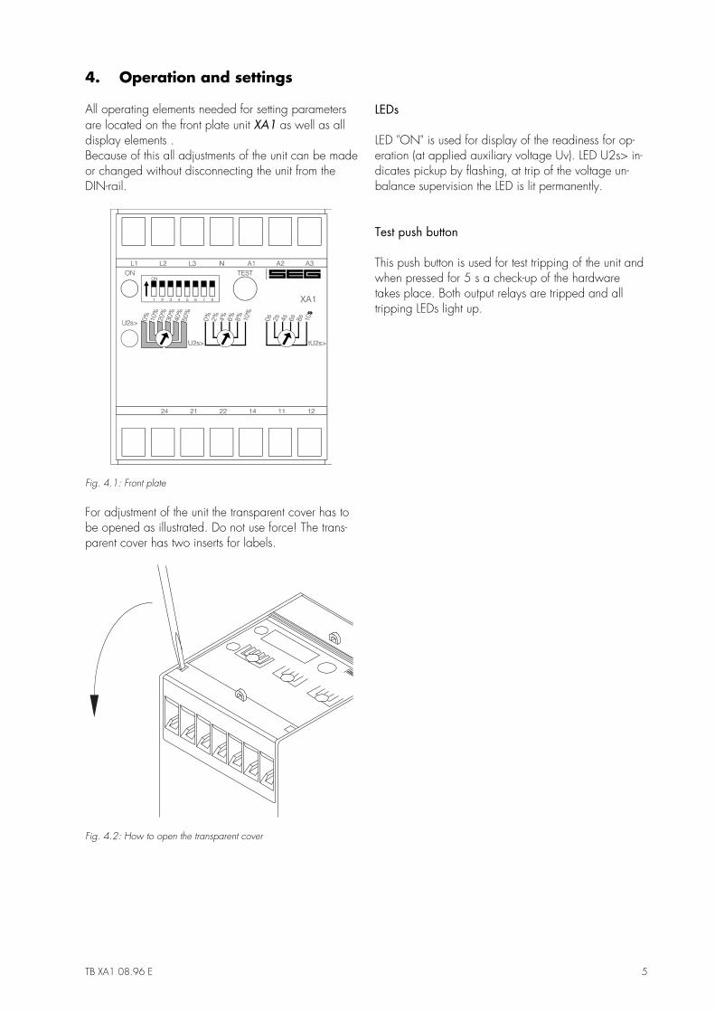
All operating elements needed for setting parametersare located on the front plate unit XA1 as well as alldisplay elements .Because of this all adjustments of the unit can be madeor changed without disconnecting the unit from theDIN-rail.
Fig. 4.1: Front plate
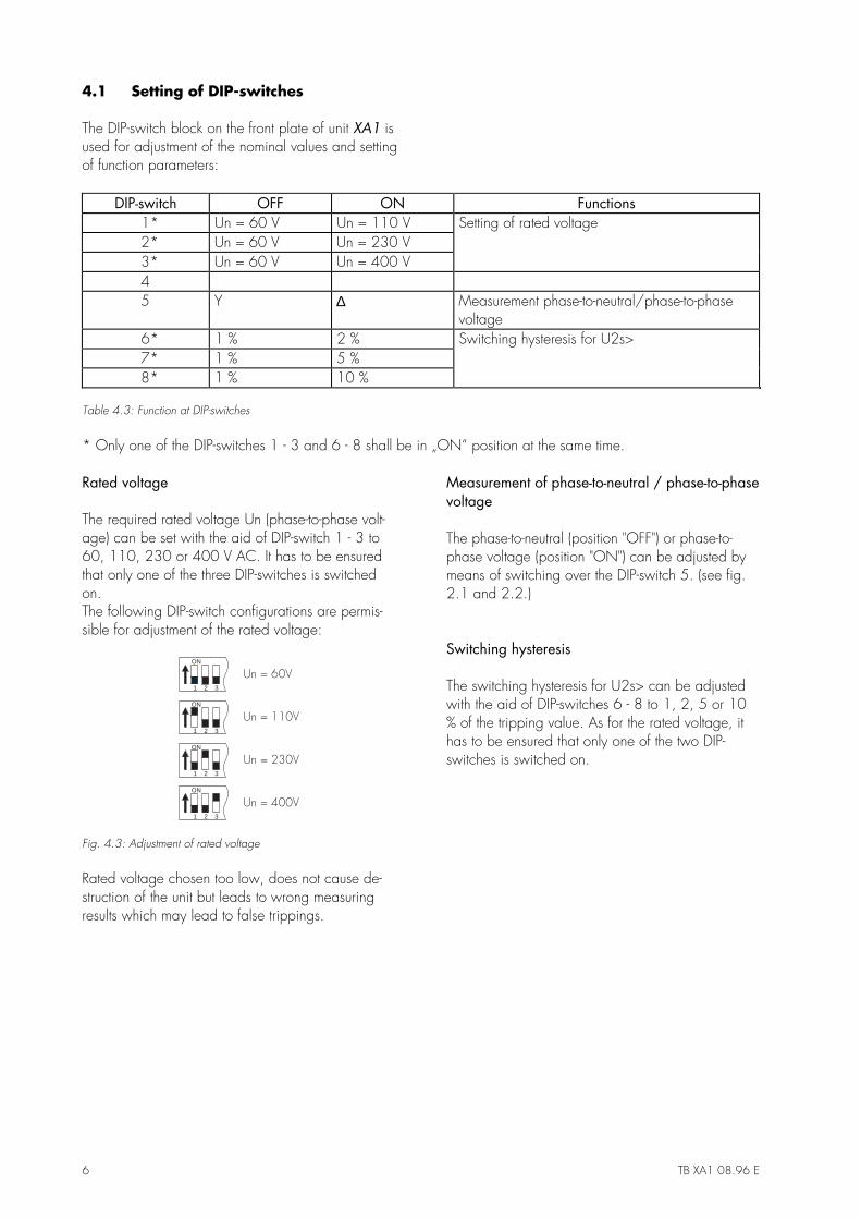
For adjustment of the unit the transparent cover has tobe opened as illustrated. Do not use force! The trans-parent cover has two inserts for labels.
Fig. 4.2: How to open the transparent cover
LEDs
LED "ON" is used for display of the readiness for op-eration (at applied auxiliary voltage Uv). LED U2s> in-dicates pickup by flashing, at trip of the voltage un-balance supervision the LED is lit permanently.
Test push button
This push button is used for test tripping of the unit andwhen pressed for 5 s a check-up of the hardwaretakes place. Both output relays are tripped and alltripping LEDs light up.
6 TB XA1 08.96 E
4.1 Setting of DIP-switches
The DIP-switch block on the front plate of unit XA1 isused for adjustment of the nominal values and settingof function parameters:
DIP-switch OFF ON Functions 1* Un = 60 V Un = 110 V Setting of rated voltage 2* Un = 60 V Un = 230 V 3* Un = 60 V Un = 400 V 4 5 Y ∆ Measurement phase-to-neutral/phase-to-phase
voltage 6* 1 % 2 % Switching hysteresis for U2s> 7* 1 % 5 % 8* 1 % 10 %
Table 4.3: Function at DIP-switches
* Only one of the DIP-switches 1 - 3 and 6 - 8 shall be in „ON“ position at the same time.
Rated voltage
The required rated voltage Un (phase-to-phase volt-age) can be set with the aid of DIP-switch 1 - 3 to60, 110, 230 or 400 V AC. It has to be ensuredthat only one of the three DIP-switches is switchedon.The following DIP-switch configurations are permis-sible for adjustment of the rated voltage:
1 2 3
ON
1 2 3
ON
1 2 3
ON
1 2 3
ON
Fig. 4.3: Adjustment of rated voltage
Rated voltage chosen too low, does not cause de-struction of the unit but leads to wrong measuringresults which may lead to false trippings.
Measurement of phase-to-neutral / phase-to-phasevoltage
The phase-to-neutral (position "OFF") or phase-to-phase voltage (position "ON") can be adjusted bymeans of switching over the DIP-switch 5. (see fig.2.1 and 2.2.)
Switching hysteresis
The switching hysteresis for U2s> can be adjustedwith the aid of DIP-switches 6 - 8 to 1, 2, 5 or 10% of the tripping value. As for the rated voltage, ithas to be ensured that only one of the two DIP-switches is switched on.
TB XA1 08.96 E 7
4.2 Setting of the tripping values
The PROFESSIONAL LINE units have the unique possibi-lity of high accuracy fine adjustments. For this, twopotentiometers are used. The course setting potenti-ometer can be set in descrete steps of 10 %. A sec-ond fine adjustment potentiometer is then used forcontinuously variable setting of the final 0 - 10 %.Adding of the two values results in the precise trip-ping value.
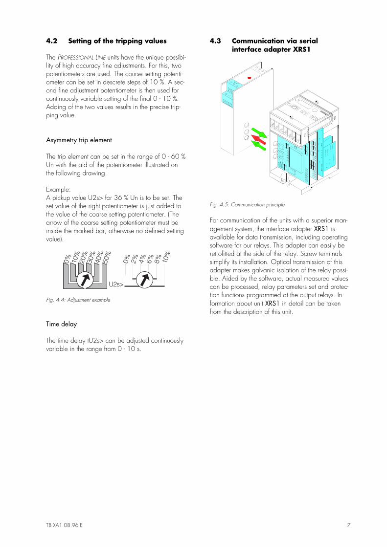
Asymmetry trip element
The trip element can be set in the range of 0 - 60 %Un with the aid of the potentiometer illustrated onthe following drawing.
Example:A pickup value U2s> for 36 % Un is to be set. Theset value of the right potentiometer is just added tothe value of the coarse setting potentiometer. (Thearrow of the coarse setting potentiometer must beinside the marked bar, otherwise no defined settingvalue).
Fig. 4.4: Adjustment example
Time delay
The time delay tU2s> can be adjusted continuouslyvariable in the range from 0 - 10 s.
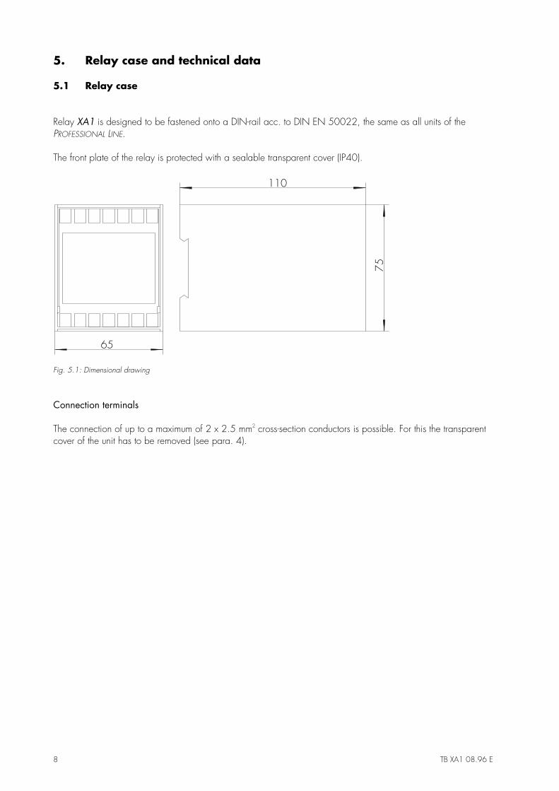
4.3 Communication via serialinterface adapter XRS1
Fig. 4.5: Communication principle
For communication of the units with a superior man-agement system, the interface adapter XRS1 isavailable for data transmission, including operatingsoftware for our relays. This adapter can easily beretrofitted at the side of the relay. Screw terminalssimplify its installation. Optical transmission of thisadapter makes galvanic isolation of the relay possi-ble. Aided by the software, actual measured valuescan be processed, relay parameters set and protec-tion functions programmed at the output relays. In-formation about unit XRS1 in detail can be takenfrom the description of this unit.
8 TB XA1 08.96 E
5. Relay case and technical data
5.1 Relay case
Relay XA1 is designed to be fastened onto a DIN-rail acc. to DIN EN 50022, the same as all units of thePROFESSIONAL LINE.
The front plate of the relay is protected with a sealable transparent cover (IP40).
75
110
65
Fig. 5.1: Dimensional drawing
Connection terminals
The connection of up to a maximum of 2 x 2.5 mm2 cross-section conductors is possible. For this the transparentcover of the unit has to be removed (see para. 4).
TB XA1 08.96 E 9
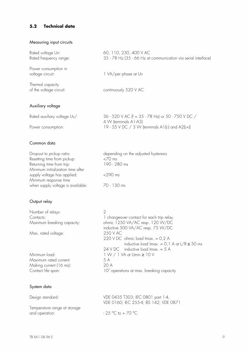
5.2 Technical data
Measuring input circuits
Rated voltage Un: 60, 110, 230, 400 V ACRated frequency range: 35 - 78 Hz (35 - 66 Hz at communication via serial interface)
Power consumption involtage circuit: 1 VA/per phase at Un
Thermal capacityof the voltage circuit: continuously 520 V AC
Auxiliary voltage
Rated auxiliary voltage Uv/ 36 - 520 V AC (f = 35 - 78 Hz) or 50 - 750 V DC /4 W (terminals A1-A3)
Power consumption: 19 - 55 V DC / 3 W (terminals A1(L-) and A2(L+))
Common data
Dropout to pickup ratio: depending on the adjusted hysteresisResetting time from pickup: <70 msReturning time from trip: 190 - 280 msMinimum initialization time aftersupply voltage has applied: <290 msMinimum response timewhen supply voltage is available: 70 - 130 ms
Output relay
Number of relays: 2Contacts: 1 changeover contact for each trip relayMaximum breaking capacity: ohmic 1250 VA/AC resp. 120 W/DC
inductive 500 VA/AC resp. 75 W/DCMax. rated voltage: 250 V AC
220 V DC ohmic load Imax. = 0,2 Ainductive load Imax. = 0,1 A at L/R ≤ 50 ms
24 V DC inductive load Imax. = 5 AMinimum load: 1 W / 1 VA at Umin ≥ 10 VMaximum rated current: 5 AMaking current (16 ms): 20 AContact life span: 105 operations at max. breaking capacity
System data
Design standard: VDE 0435 T303; IEC 0801 part 1-4,VDE 0160; IEC 255-4; BS 142; VDE 0871
Temperature range at storageand operation: - 25 °C to + 70 °C
10 TB XA1 08.96 E
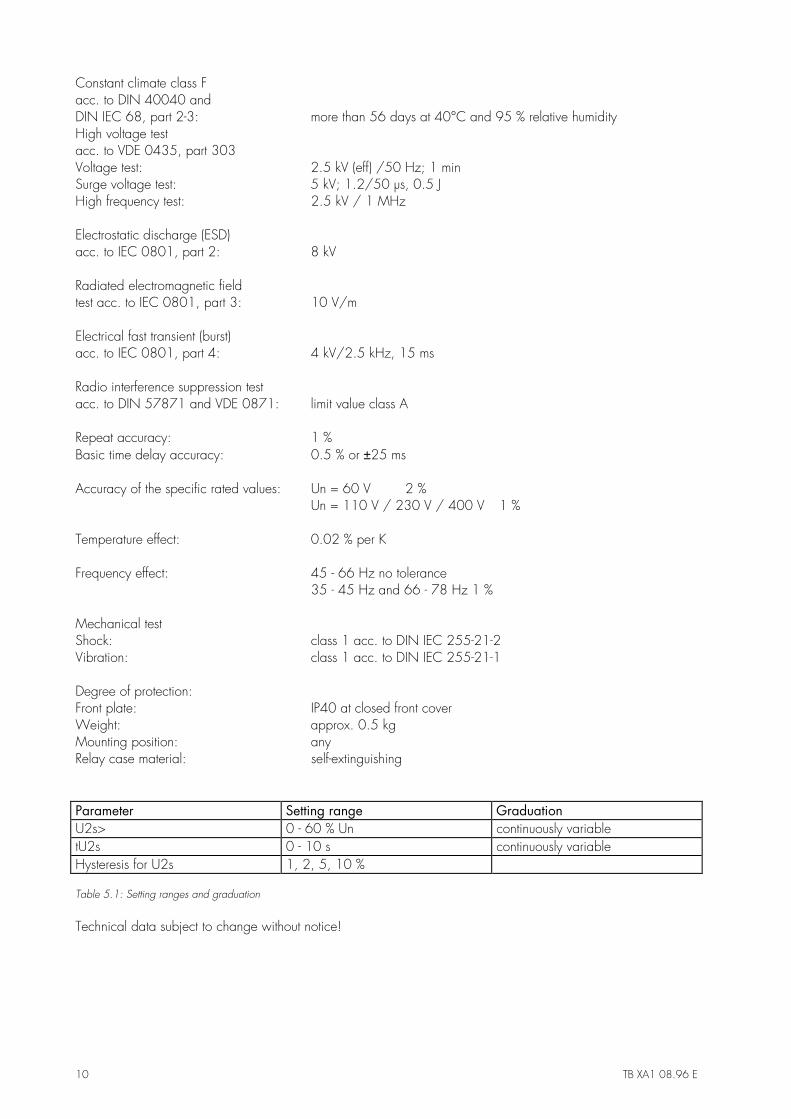
Constant climate class Facc. to DIN 40040 andDIN IEC 68, part 2-3: more than 56 days at 40°C and 95 % relative humidityHigh voltage testacc. to VDE 0435, part 303Voltage test: 2.5 kV (eff) /50 Hz; 1 minSurge voltage test: 5 kV; 1.2/50 µs, 0.5 JHigh frequency test: 2.5 kV / 1 MHz
Electrostatic discharge (ESD)acc. to IEC 0801, part 2: 8 kV
Radiated electromagnetic fieldtest acc. to IEC 0801, part 3: 10 V/m
Electrical fast transient (burst)acc. to IEC 0801, part 4: 4 kV/2.5 kHz, 15 ms
Radio interference suppression testacc. to DIN 57871 and VDE 0871: limit value class A
Repeat accuracy: 1 %Basic time delay accuracy: 0.5 % or ±25 ms
Accuracy of the specific rated values: Un = 60 V 2 %Un = 110 V / 230 V / 400 V 1 %
Temperature effect: 0.02 % per K
Frequency effect: 45 - 66 Hz no tolerance35 - 45 Hz and 66 - 78 Hz 1 %
Mechanical testShock: class 1 acc. to DIN IEC 255-21-2Vibration: class 1 acc. to DIN IEC 255-21-1
Degree of protection:Front plate: IP40 at closed front coverWeight: approx. 0.5 kgMounting position: anyRelay case material: self-extinguishing
Parameter Setting range GraduationU2s> 0 - 60 % Un continuously variabletU2s 0 - 10 s continuously variableHysteresis for U2s 1, 2, 5, 10 %
Table 5.1: Setting ranges and graduation
Technical data subject to change without notice!
TB XA1 08.96 E 11
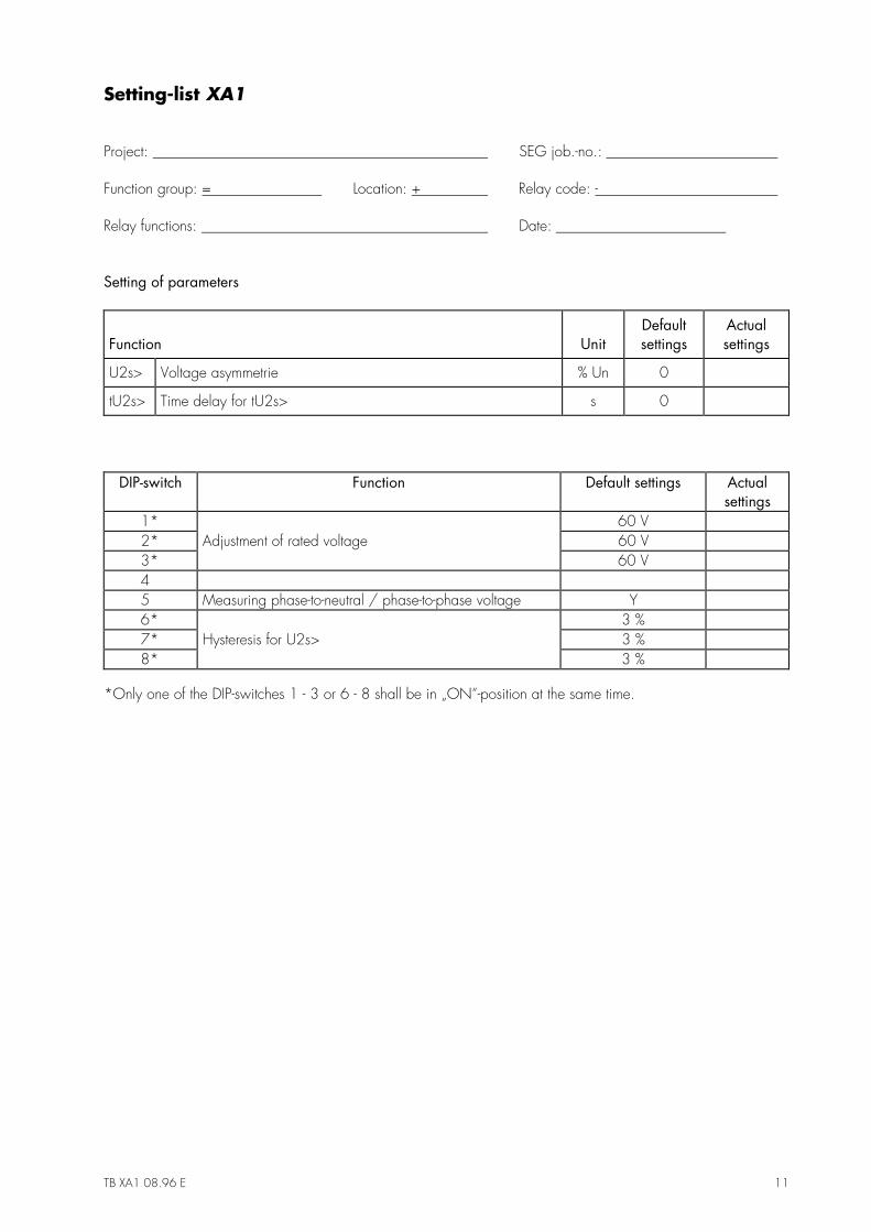
Setting-list XA1
Project: SEG job.-no.:
Function group: = Location: + Relay code: -
Relay functions: Date:
Setting of parameters
Function UnitDefaultsettings
Actualsettings
U2s> Voltage asymmetrie % Un 0
tU2s> Time delay for tU2s> s 0
DIP-switch Function Default settings Actualsettings
1* 60 V 2* Adjustment of rated voltage 60 V 3* 60 V 4 5 Measuring phase-to-neutral / phase-to-phase voltage Y 6* 3 % 7* Hysteresis for U2s> 3 % 8* 3 %
*Only one of the DIP-switches 1 - 3 or 6 - 8 shall be in „ON“-position at the same time.

12 TB XA1 08.96 E