Embed Size (px)
Citation preview

VOL. 7 , NO. 4 , OCTOSER- OECEMBEcR 1980 s~('l .. J r nrrt•'N Auo..m 1m

A SERVICE PUBLICATION OFLOCKHEED-GEORGIA COMPANYA DIVISION OFLOCKHEED CORPORATION
EditorCharles I. Gale
Associate EditorsJames A. LoftinSteve PalmerWilliam H. ShepherdPatricia A. Thomas
Vol. 7, No. 4, October-December 1980
CONTENTS
2 Focal PointWalt Hensleigh, ManagerFlying Operations
3 Desert OperationsSuggestions for operatingand maintaining the C-130in desert-like conditions.
11 The Air Turbine MotorA brief look at the operationand maintenance of rhe ATM.
16 MLG Track Shoe Shop AidNew tool facilitates trackshoe servicing.
Cover: An ancient form of desert transportationbears witness to the desert operations capabilitiesof the Hercules aircraft.
Published by Lockheed-Georgia Company, a Division ofLockheed Corporation. Information contained in thisissue is considered by Lockheed-Georgia Company to beaccurate and authoritative; it should not be assumed, how-ever, that this material has received approval from anygovernmental agency or military service unless it isspecifically noted. This publication is for planning andinformation purposes only, and it is not to be construedas authority for making changes on aircraft or equipment,or as superseding any established operational or main-tenance procedures or policies. The following marks areregistered and owned by Lockheed Corporation:” ", “Lockheed”, “Hercules”, and “JetStar”.
Written permission must be obtained from Lockheed-Georgia Company before republishing any material in thisperiodical. Address all communications to Editor, ServiceNews, Department 64.22, Zone 278, Lockheed-GeorgiaCompany, Marietta, Georgia, 30063. Copyright 1980Lockheed Corporation.
Focal&pintWalter E. Hensleigh
Lockheed-Georgia’s Flying Op-erations people have as theirprimary purpose service to ourcompany and to our customer.We serve Manufacturing by per-
forming the final “proof of thepudding” functional check on
new and modifird airplanes. We support Engineering with engineering test crews as design advisors,and WC also provide flight crews to perform experimental and engineering tests on test airplanesand simulators. We support our customers by offering flight crew qualification training, opera-tional support, acceptance flight assistance, delivery flight service, flight planning support, andtechnical assistance. We operate all company transportation and flight demonstration airplanes,which on occasion arc used to support our customers and to help them evaluate our products.Assistance to all flight crews using or visiting our facility is provided by our control tower andflight equipment service.
Although all employees at Lockheed-Georgia Company arc dedicated to offering thoroughlyprofessional performance on behalf of our customers, Flying Operations is among the best friendsour customers have in the company. This is only natural. Since we fly our products, demonstrateour products, present our products on acceptance flights, and train in our products, it follows thatwe arc most interested in our airplanes being reliable, serviceable, easy to operate, and safe. In ourdaily duties, therefore, we frequently reflect an image which gives us the appearance of beingagents for the customer. This is in fact why Lockheed-Georgia has flight crews: to ensure that eachof our airplanes will perform as advertised, and is built to continue to perform as advertisedthroughout its entire service life.
Our activities in establishing normal and emergency procedures, monitoring of handbooks,teaching ground school, and acting as advisors on product improvements arc as extensive as ourflying duties. There arc the areas where we might be of greatest assistance to you, our customer.We have crew members who have been flying for us since the first production C-130 was beingmanufactured. They have flown every model that we have ever built. We hope you will nothesitate to call on us to help you with your training and operational problems.
Sincerely,
Walter E. HensleighDirector of Flying Operations
T. J. Cleland Director
CUSTOMERSERVICEDIVISION
A. H. McCrumDIRECTOR
INTEGRATEDLOGISTICS SUPPORT
DIVISION
J. L. T h u r m o n dDIRECTOR
CUSTOMERSUPPLY
DIVISION
M. M. HODNETT
DIRECTOR

by H. B. Armitage, Engineering Test PilotR. M. Holdernan, Engineering Specialist
Climate and the special problems imposed by environ-mental extremes are major factors which must be fullyevaluated before any type of mechanical equipment canbe operated successfully at a given location. There isusually a close relationship between the degree to whichmachinery can be protected from the adverse effects ofan unfavorable climate and the length of its service life.
In no situation is this principle more readily applicablethan in the case of airplanes which are operated in desertregions. Of all possible climatic extremes, no terrestrialenvironment is potentially more rapidly destructive tokey aircraft components than that of the arid and semi-arid regions of the world. Every modern, turbine-poweredaircraft, regardless of make or type, can be seriouslyaffected by desert operations. It follows that operationaland maintenance techniques which serve to counter theeffects of desert conditions will pay substantial dividendsin terms of improved aircraft reliability, lower operatingcosts, and extended service life.
The reason that desert conditions often have such delete-rious effects on aircraft can be found in an examination ofthe desert air itself. The air in desert regions often con-tains a heavy burden of sand and dust particles that havebeen picked up from dry surface soils and carried aloft bythe wind. These particles are quite small in size and, inthe absence of sufficient rainfall to return them to theground, tend to become more or less permanent com-ponents of the atmosphere.
Although dry desert air has long been recommended asbeneficial to human sufferers of allergies and certain lungdiseases, the effects of an arid climate on precision ma-chinery are less benign. Mechanical equipment is muchmore vulnerable to damage from airborne sand and dustthan are living organisms. An important reason for this isthat most living creatures have effective internal systemswhich help them eliminate any potentially harmfulingested particles. Machines, on the other hand, generallymust be protected from solid contaminants in the environ-ment by external devices such as covers, screens, and
filters. Even when superbly designed, this type of pro-tection is seldom completely foolproof; nor is it practicalfor all types of equipment. The unhappy fact of thematter is that in sandy or dusty climates, it is next toimpossible to prevent at least some particulate matterfrom reaching internal parts where critical workingtolerances can be affected.
With aircraft, the problems posed by sand and dust con-tamination are particularly difficult to control. It happensthat airplanes are often used and stored in such a way thatthey are exposed to the very worst environmental con-ditions any locale has to offer. In the desert, this meansplenty of heat, wind, and dust. The suspended contami-
3
nants in the air, together with the larger particles stirredup from runways and taxiways by propellers and jetexhaust, can penetrate to the interior of even the mostcarefully protected aircraft components. Once inside, theparticulate matter is likely to remain there and causetrouble, clogging passages, eroding surfaces, and convert-ing lubricants into abrasive slurries.
Solid particles carried by the air are clearly the funda-mental cause of many of the most serious operationaland maintenance problems commonly encountered indesert localities, but this is by no means the only problemarea. Another source of trouble is heat. The high ambienttemperatures typical of many arid regions not only con-tribute to the dryness, but subject aircraft componentsand systems to stresses specifically related to excessiveheat. This tends to complicate an already rather challeng-ing maintenance situation.
In the case of turbine-powered aircraft, undoubtedly thesingle most troublesome problem attributable to desertoperations is compressor erosion. Each siliceous particlethat is ingested by an engine invariably strikes a com-pressor blade, vane, or seal; usually at high velocity, andoften under conditions of elevated temperature andpressure. It is, quite simply, a form of sand blasting. Overa period of time, even the most resistant of surfaces willwear away under this kind of assault.

power than is required to support propeller operation at agiven throttle setting.
What is a Desert?
The dictionary defines a desert as an area in whichthe prevailing conditions include generally high day-time temperatures, little rainfall (less than 10 inchesannually), persistent winds, and dusty or sandy soils.But as far as the operation of a modern airplane isconcerned, anyplace where high temperatures, dryconditions, and blowing sand or dust are present- even if only temporarily - qualifies as a “desert.”
Almost every aircraft operator encounters suchconditions from time to time, and that is why thisarticle is important. No matter where your home baseis located, the information in “Desert Operations”can make a real contribution towards ensuring thatyou will get the best possible service from yourHercules aircraft.
It does not necessarily even take very much time. Com-pressor damage due to sand ingestion can show up quiterapidly if the air quality is poor. Remember that when anAllison T56-A-15/501-D22A power plant is on speed, over
426,000 cubic feet of air is passing through its compressorevery minute. With such a large volume involved, thepresence of even a relatively modest amount of sand ordust in the atmosphere can make a measurable differencein engine service life.
The principal effect of sand and dust erosion on com-pressor performance is a gradual reduction in dischargepressure and volume. This is accompanied by a decline inefficiency and an increase in the incidence of such prob-lems as hung starts, compressor stalls, and engine “bog-down” - a condition in which the engine supplies less
Unfortunately, power plant damage from ingested sandand dust is not limited to compressor erosion. Amongother things, dust-laden air can lead to plugged fuel con-trol compensator probes, abnormal flame patterns in thecombustion liners due to dirty fuel injectors, cloggedengine anti-icing passages, sluggish bleed air manifoldvalves, and a general shortening of the service life of manyother engine and propeller components because of oilcontamination.
Nor are aircraft systems beyond the engines immune fromenvironmentally-caused damage in the desert. Everymoving part, every valve, switch, or cam; every duct,passage, or seal may have its function impaired by air-borne sand and dust or be degraded by long exposure toexcessive heat.
Experience is at the heart of most of the principles andpractices that have become established over the years inconnection with aircraft operation. So it is with thosespecial techniques which have been found useful in pro-tecting aircraft used for desert operations. No particularlysophisticated or unusually elaborate procedures areinvolved. What is involved is the consistent applicationof proven, “desert wise” practices in all situations wherethe aircraft and the environment interface.
The list of operating and servicing limits presented heredoes not by any means exhaust all possible ideas thatcould help protect your aircraft from harsh climatic con-ditions, but it does provide a proven data base from whichto start. It is not possible to protect an aircraft from allof the rigors of the desert, but the use of these techniquesand procedures will make a real contribution towardminimizing the amount of punishment that your Herculesaircraft will have to absorb when it is operated and main-tained in the arid regions of the world.
Compressor rotor blades, showing effects of sand erosion. Note particularly

OPERATIONAL RECOMMENDATIONS
1. Taxi with all engines in low speed ground idle (LSGI)whenever possible. This practice will greatly reduce theamount of sand and dust being drawn into the intakesand it will also aid in cooling engine oil since less engineheat is developed in LSGI.
2. If it is necessary to use high speed ground idle (HSGI)during ground maneuvering at speeds below 40 knots,avoid moving the throttles below the ground idle detent.Below ground idle, blade action is reversed and blowsdebris forward where it may be subjected to ingestion bythe engines.
3. During sharp turns on the ground (180’ on the run-way, etc.), use minimum speed and use LSGI on theengines inside the turn to help reduce the possibility thatdebris will be drawn into the engines.
4. If it is necessary to move the aircraft backwards byusing reverse thrust, first stop the aircraft and, whileholding the brakes, position the throttles above flightidle to blow the sand and dust aft. Then move the air-craft backwards, utilizing the minimum reverse power onall four engines.
5. The flaps should be retracted during all taxi oper-ations and should be lowered just prior to takeoff. Ex-tended flaps deflect prop blast to the ground during taxi,stirring up debris and thus increasing the possibility ofthese particles being ingested by the engines, APU, andair conditioning units.
6. Minimize the operation of the air conditioningsystems during landings and while on the ground to re-duce sand and dust contamination of the heat exchanger.
Turn off the cargo air conditioning system to aid in thiseffort whenever possible. The flight station air condition-ing may be left on, since its intake is located far enoughforward on the fuselage to preclude ingestion of debristhrown up by prop blast.
7. Operate the APU or GTC/ATM only when requiredfor electrical or pneumatic power. This will minimize theingestion of sand and dust by the equipment. 5
8. Make the reverse thrust check (prior to takeoff) afterthe engine run-up. The sand and dust will be blown aftduring the engine run-up; hence, less will be ingestedduring the reverse check.
9. Minimize flight time in blowing sand or when there issand and dust in the atmosphere by climbing and descend-ing as rapidly as practical.
10. Cycle the wing, empennage, and engine anti-icingsystems during each flight to prevent dust and sand con-tamination from causing the anti-icing valves to stick.
11. During landings, move the throttles from FLIGHTIDLE to GROUND IDLE to MAXIMUM REVERSE assoon as practical; then return to GROUND IDLE beforeground speed reaches 40 knots. Below 40 knots, thepropellers move dust and sand forward of the airplanewhere these particles are ingested by the engines.
12. If blowing sand or dust is present, install the inletplugs after parking, even during turnaround stops. Installexhaust plugs as soon as the tail pipes cool. Also close theoil cooler flaps.
13. During hot weather operation, avoid sudden powerchanges. Normal engine acceleration should be experi-

Install engine inlet covers after parking.
enced; however, engine bog-down is more likely underhigh-temperature conditions. If engine bog-down isexperienced, notify maintenance.
14. Minimize the use of the wheel brakes, since they willheat rapidly and not cool at the normal rate under highambient temperatures.
615. To produce the coolest oil temperatures for revers-ing, taxi, and ground maneuvering in extremely hotclimates, manually open the oil cooler flaps and positionthe switch to OPEN and FIXED below 15,000 feet.Remember that oil temperatures above 85’C are detri-mental to engine components.
16. Perform NTS checks frequently while operating inthese conditions to ensure proper operation of the nega-tive torque system.
17. Park the aircraft facing into the wind wheneverpractical. Tailwind starts in high ambient temperaturesincrease the possibility of “stall starts”, overtemperatureconditions, and turbine damage. A stall start occurs duringan engine start attempt and appears as stagnated rpm atapproximately 35 to 55% rpm, with TIT continuing torise uncontrollably beyond start limit.
MAINTENANCE RECOMMENDATIONS
The following recommended maintenance procedures,practices, and techniques are intended to complementestablished maintenance practices. The use of these rec-ommendations will result in increased service life of com-ponents by reducing sand and dust contamination ofaircraft components. These procedures will also help tominimize the adverse effect of high ambient temperatureson aircraft systems.
Please note that the recommended time spans betweenperformance of certain maintenance checks are “bestjudgment” averages based on studies of Hercules aircraftoperations under desert conditions. These time spans maybe adjusted by individual operators according to theseverity of the local climate.
1. Remove, clean with approved solvent, and reinstallengine starter control valve filters every 25 engine starts.This will reduce the possibility of the valve sticking orfailing to regulate the air pressure to the starter. Failureto regulate air pressure correctly results in extremely rapid
Blow sand and dust aft before backing aircraft with reverse thrust.

starter degradation. For Bendix starter valves, refer to theapplicable Bendix publication for filter location.
2. Check for proper operation of the engine startervalves every 50 hours. When using bleed air from anengine operating in HSGI, the starter control valve shouldregulate the pressure to the starter scroll of the enginebeing started at between 36 and 42 psi during enginerotation. It should also drop to 0 psi within five secondsafter the flight station starter switch is deactivated.Failure of the valve to function in this manner can causeserious damage to the starter and engine gearbox bygenerating high impact loads, excessive torque, andexcessive rpm after switch deactivation. If the regulatedpressure is low, long, hot starts and reduced turbine lifewill result. To check the operation of Bendix startervalves, Bendix suggests that operators tee in a directreading gage and measure the starter control valve pressureat the “B” check (200 hours of aircraft time), especiallyif starter problems have been experienced. The tee shouldbe installed at the pressure sensing line port of the starterscroll so that accurate readings of actual starter operatingpressures may be obtained. When the gage is installed, usebleed air from an engine operating in HSGI. Start theengine being checked, observing the pressure gage. If thevalve does not operate within the above limits, replace thevalve.
3. Use a rag to wipe out the engine inlets when the inletplugs are removed. Some blowing sand can bypass theinlet plugs and be ingested during engine starting.
4. Maintain between 11 and 12 gallons of engine oil inthe tank. This provides the maximum oil quantity possibleto absorb engine-generated heat and assists in preventinghigh oil temperatures during ground operations. However,
do not service the oil tank with over 11 gallons when theoil is cold since this will result in overfilling.
5. Be sure that the engine throttle-to-coordinator-to-fuelcontrol rigging is maintained to specified tolerances. Thiswill ensure optimum engine response to throttle position.Check every 50 hours in accordance with the instructionscontained in the applicable maintenance documents.
6. Maintain the engine coordinator to propeller linkagewithin the specified tolerances. This will ensure the properrelationship of propeller blade angle to throttle and fuelcontrol position. Check every 50 hours.
7. When maintenance actions require ground operationof an engine, move the throttles slowly, utilizing approxi-mately twice the normal time required. During highambient temperatures, the engine power change responserate is slower than the propeller response rate. Slowthrottle movements minimize the possibility of the pro-peller “getting ahead” of the engine and causing somedegree of engine overload and degradation of compressoror turbine.
8. Remove, clean with approved solvent, and reinstallthe engine 14th stage bleed air filter every 25 hours toreduce contamination of the speed sensing valve. Mal-function of the speed sensing valve can result in the com-pressor’s 5th and 10th stage bleed valves not closingcompletely, causing power loss and, under extreme 7conditions, engine bog-down. Refer to the appropriateengine maintenance manual for removal and reinstallationinstructions.
9. Remove, clean with approved solvent, and reinstallthe 5th and 10th stage engine compressor bleed valves
Dust cloud stirred up by reversed propellers during landing can be limited by appropriate throttle management.

every 100 hours. Contamination with dust, sand, or oilwill cause the valves to operate sluggishly or not closeproperly. Such a condition results in power loss and cancause an unscheduled engine rundown. Just one of thefour 5th~stage bleed valves remaining open at takeoffpower results in a loss of approximately 130 horsepower,and one of the four 10th~stage bleed valves remainingopen at takeoff power results in a loss of approximately270 horsepower.
10. Clean the engine pressure probe every 50 hoursaccording to the following procedure:
a. Disconnect the compressor inlet pressure sensingline at the fuel control connection. Note: Refer to AllisonPublication 4RC2, Subject No. 75-11-0, Figure 1, Item11. for connection location.
b. Using an air pressure cleaning gun at the disconnectedend of the pressure sensing line, flush cleaning solventthrough the line and out the sensing tip until the solvent isdirt-free. Note: Refer to Allison Publication 4RC2, Sub-ject No. 75-l l-0, Figure 1, for sensing tip location.
c. After completion of Step (b), blow dry air throughthe line and out the tip to remove any loose dirt and todry out the line.
8 CAUTION
Do not apply shop air pressure or introduce solventinto the fuel control.
d. Remove the bellows housing overboard drain plugfrom the fuel control and apply a maximum of 5 psi airpressure to the overboard drain opening in the fuelcontrol.
e. Reinstall the pressure sensing line disconnected inStep (a) above and plug removed in Step (b) above.Replace safety wire as required.
The procedure just discussed will prevent the pressuresensing system of the fuel control from becoming con-taminated, which results in an extremely lean fuel flowschedule. It is possible for an extremely lean fuel scheduleto cause engine bog-down, especially when the throttlesare below crossover.
11. Make sure that LSGI is maintained at between 69.0and 75.6% rpm. Refer to the appropriate engine main-tenance manual for the adjustment procedure.
12. Keep the temperature datum valve null orifice ad-justed to admit as much fuel as possible without start TITlimits being exceeded. This provides the maximum fuelflow below crossover and reduces the possibility of enginebog-down.
13. Make sure that the temperature datum amplifierstart limit is set correctly. Check every 50 hours and any-time there is a reported high start TIT. This will preventturbine damage from excessive starting temperature.
14. During overhaul of the engine speed sensing control(P/N 7854687), specify that switch No. 1 be set to actu-ate at the minimum rpm allowed in Allison PublicationNo. 4RC3, Subject No. 73-12-0, Table III. During in-service time, replace any control unit that consistentlydoes not provide fuel flow and ignition between 16% and20% rpm during the engine start cycle. This will providethe earliest possible light-offs, and allow for maximumturbine assistance to accelerate the engine to an on-speedcondition. The possibility of long or “hung” starts is thusmuch reduced.
1.5. Visually and electrically check engine thermocouplesevery 100 hours, in accordance with the proceduresdescribed in the applicable maintenance manuals. Thiswill assist in preventing engine turbine damage.
16. Check the operation of the engine anti-icing valvesevery 50 hours. At 100% rpm, there should be approxi-mately 900 inch-pounds of torque reduction when engineanti-ice is turned on. These valves are “fail-safe” in theopen position; in the event of a bleed system failure, thevalves automatically open. Therefore a malfunction cancause a loss of approximately 170 horsepower per engine,possibly causing an engine bog-down.
17. Instruct your fuel control overhaul facility to takeadvantage of all tolerances given in Allison PublicationNo. 4RC3, Subject No. 73-3-1, Figure 710, to provide thehighest allowable fuel flow with the temperature probe inthe +1 10 degree F bath. This will help make certain thatat extremely high ambient temperatures, the engine is notrunning lean enough to be subject to “lean blowout.”Lean blowout occurs during a rapid retardation of thethrottle, or during flight when descending from altitude.It can also happen when shifting to LSGI. The symptomsare that the engine behaves just as though fuel were inten-tionally cut off, with rapid deterioration of rpm and TIT.
18. When maintenance action requires engine operation,if possible select times when there is little or no blowingsand. If you are in an area where there is sand on the rampor on an adjacent area, water down a circle approximately30 feet in diameter under each propeller. This will reducesand ingestion by the engines.
19. Wash down the engines frequently. Do not allow theinside of the nacelle to become contaminated with sand ordust. Frequent washing reduces the possibility of inlet airor lubricating oil becoming impure. Also, the washing willallow normal engine cooling and prevent hot spots due tolack of heat dissipation on contaminated surfaces.

20. Install engine inlet and air conditioning inlet plugseach time the engines are shut down. This will preventsand or dust from entering the inlets and being ingestedduring engine starting.
21. Install engine tail pipe plugs after the engines havebeen shut down for approximately 30 minutes. This willprevent airborne contaminants from entering the turbineand causing turbine blade or vane sulfidation.
22. Borescope each engine turbine every 100 hours ofoperation in accordance with approved procedures tocheck for signs of overheating or mechanical damage.
23. Ensure that the alignment of the air inlet scoop tothe engine inlet housing is maintained with no more thanl/4-inch step at any point; check visually daily. Thischeck ensures that there is minimum distortion of thecompressor face pressure pattern. During high ambienttemperatures, engine compressor face pressure is morecritical than at normal temperatures. Sufficient distortionof the compressor face pressure pattern results in com-pressor stall and engine bog-down.
24. Maintain the propeller ground idle blade angle at 5.0to 5.5 degrees. This will ensure a positive aerodynamicblade angle for ground maneuvering and thereby reducethe possibility of sand and dust ingestion by the engines.However, this blade angle may also increase the starttime under high ambient temperature conditions, and itmay cause hotter brakes during taxi. The ground idleblade angle should be checked every 50 hours in accor-dance with the instructions in the applicable maintenancemanual.
25. Check and lubricate the NTS bracket clearanceevery 50 hours in accordance with the instructions in the
Correct alignment must be maintained between air inletscoop and engine housing.
NTS bracket: to check operation, insert blade of screw-driver at point indicated (see text).
applicable maintenance handbook. In addition, ensureproper and free movement of the NTS bracket and leverby following this procedure:
Note: This procedure should be done with the propellerauxiliary pump running and throttle above flight idle.
a. Insert a screwdriver between the engine NTS plungerand the engine lever.
b. Manually actuate the NTS linkage by prying theengine lever forward. Observe blade movement.
c. Slowly release the pressure on the engine lever.
d. Ensure that the needle roller ring returns smoothly toits original position.
e. Should any erratic or jerky movement be noted inStep (d), remove, replace, repair, or lubricate the bracketas required.
Note: If the NTS bracket is replaced, be sure to useHamilton Standard P/N 738338.
26. Remove, clean with approved solvent, and reinstallthe propeller control vent filter every 150 hours. Contami-nation of this filter can cause erratic propeller governingor an unscheduled engine rundown by causing too higha propeller blade angle for the engine power, resulting inrpm decay.
27. Drain the propeller control oil every 150 hours byremoving the drain plug in the bottom of the propellercontrol assembly. Then service with fresh oil (approxi-mately 6 qts). Although this does not replace all thepropeller oil, it will reconstitute the oil and reduce con-tamination. This will reduce seal, gear, and bearing wearwhich causes erratic governing. In turn, poor propellergoverning can cause too high a blade angle for the enginepower and an unscheduled engine rundown.

28. During maintenance actions requiring APU/GTC orengine operation, do not use the air conditioning systemunless it is required for system checks. This will preventsand ingestion which can result in system contaminationand cause abnormal wear, malfunctions, and unscheduledremoval of components.
29. During maintenance engine runs, turn the APU/CTCoff and close the door before operating No. 1 or No. 2engines above LSGI. This prevents the APU from ingestingsand and dust generated by the propeller ground effectvortex.
30. During maintenance requiring APU and engineoperation, keep operating time to a minimum and when-ever possible operate the engines in LSGI only. This willreduce sand and dust ingestion into components whichoperate at a high rpm.
31. Remove, sonic clean, and reinstall the outflow valvebleed air filter every 100 hours and replace the throwawayfilter to reduce the possibility of a cabin pressurizationsystem malfunction. Refer to the appropriate main-tenance handbook for filter location.
10
32. Remove and replace the two throwaway paper matfilters in the cabin pressure controller every 100 hours toreduce the possibility of cabin pressurization systemmalfunction. Refer to AiResearch publication number21-30-37, Figure 1102, Items 16, 17, 18,23, 24, and 25or the appropriate maintenance handbook for filterlocations.
33. Clean and lubricate the main landing gear (MLG) andthe flap jackscrews daily to reduce ball nut wear. It is alsorecommended that only P/N EA4344( ) flap jackscrewassemblies and Calco P/N 8353 screw assemblies for theMLG be used. These units are designed to remove con-taminants from the screw threads before the threads enterthe ball nut assemblies and induce a high wear rate.
34. Replace all hydraulic reservoir vent filters every 100hours. This wilI reduce the possibility of contaminatedhydraulic fluid or pump cavitation and damage becauseof poor reservoir venting.
35. Replace all hydraulic pressure filters at l/2 thenormal interval. This will reduce wear of hydraulic sealsaround moving parts.
37. When the aircraft is stationary, allow air to circulatethrough the fuselage during dry weather if there is noserious problem with blowing sand or dust. Open thehinged windows in the flight station, the overhead escapehatch, the crew entry door, the rear entrance doors, theramp, and the cargo door. The air circulation will preventexcessive heat build-up in the fuselage and the degradationof fuselage-installed components that can result.
38. Lubricate the aircraft every 100 hours of operationwith new grease. Force the old grease out of all pressure-lubricated points. Wipe off all excess grease. This lubrica-tion helps remove sand- and dust- contaminated lubricantsfrom moving parts and reduces wear.
It is important to remember that an airplane and itscomponents are designed and tested with certain environ-mental parameters in mind. The procedures that areestablished for operating and maintaining aircraft arepredicated on the assumption that aircraft equipmentwill be used within the normal range of these parametersmost of the time. Whenever an aircraft - or for thatmatter any piece of mechanical equipment - is operatedextensively under environmental conditions which aresignificantly harsher than those for which it was designed,appropriate special operating and maintenance proceduresare required to ensure normal service life.
The environmental conditions of the desert clearly placesevere stresses on the components and systems of anyaircraft. But it is possible to neutralize, or at least miti-gate, the worst effects of desert operations. Careful andconsistent application of the techniques described in thisarticle will help keep your Hercules aircraft safe anddependable at the lowest possible cost.
36. During maintenance, do not “power up” any electri-cal components that are not required to accomplish themaintenance action. This will avoid the generation ofexcessive heat which could lead to impaired operation ofthe components and an undue increase in the failure rate.

ATM System Description
the
by C. E. Madison, Training SpecialistA. K. Millsaps, Service Representative
Although the air turbine motor (ATM) has over the yearsproven to be reliable and relatively easy to maintain, likeall mechanical devices, it does demand a certain amountof attention. Also, some Hercules aircraft operatorsoccasionally encounter ATM maintenance problems notcovered in the maintenance manuals. This article describesthe operation and purpose of the ATM, and includesservicing tips and hints on troubleshooting some of theless common problems that are encountered in the field.
The ATM is installed in all Hercules aircraft equipped withthe gas turbine compressor (GTC). Nearly 1400 Herculesutilize the GTC/ATM combination, from the first Amodel through the early H models. The GTC/ATM com-bination has been replaced on recent model productionHercules by an auxiliary power unit (APU) which com-bines most of the functions of the two units. At present,there are no plans to retrofit the Hercules fleet with thenewer APU, which means that the ATM should be aroundfor a long time to come.
Purpose of the ATM
The purpose of the ATM is to provide a standby sourceof electrical power and, on the earlier A models, toprovide emergency hydraulic pressure. The ATM is anintegral part of the self-sufficiency concept that allowsthe Hercules aircraft to operate in remote areas withoutthe need for ground support equipment.
Location and Access to the ATM
The ATM is installed in the upper left wheel well abovethe forward tire. Access is provided above the wheel wellfairing. A small, rectangular access panel is used to checkthe oil, and a larger panel can be removed for access to theentire unit.
CAUTION
Do not use the ATM exhaust outlet as a step. To do socould bend the turbine exhaust duct and warp the turbinehousing (the volute), possibly causing the turbinewheel to strike the housing.
Essentially, the ATM is a gear tram turned by an air-driventurbine wheel. It contains an integral oil pump, with thehollow gear housing utilized as an oil reservoir. There aretwo drive splines integral to the gear train, one turning8,000 rpm for the AC generator and the other turning6,000 rpm for a hydraulic pump mounted on the secondspline on the A model Hercules, but not used on the laterHercules models. Air necessary for turning the ATM canbe obtained from the GTC, from the 14th stages of theaircraft engine compressors, or from an external groundsupport compressor. If the engine-driven generators arenot operating, DC electrical power necessary for the ATMcontrol can be obtained from an external power cart orfrom the aircraft battery.
OPERATION
The normal operating speed of the ATM is 43,000 rpm.This speed can be monitored by observing the ATM ACgenerator frequency meter for a reading of 400Hz. Thespeed is precisely controlled by modulating the amountof bleed air that turns the turbine wheel.
Two units control the bleed air flow - a governing devicecalled the speed controller (governor) and a butterflyvalve referred to as a modulating valve. Since a number ofproblems associated with the ATM can be traced to these
11
two units, let us take a closer look at their operation.

Speed Controller
The speed controller (governor) is mounted on the loweraft side of the ATM housing and is driven by a couplingin the oil pump (Figure 1). Control air tapped from thedownstream side of the shutoff valve is directed into thespeed controller and modulating valve by way of a waterseparator, filter, and a pressure regulator which limitscontrol pressure to 55 psi (Figure 2). For the purposes ofthis discussion, we shall call the air paths which lead tothe speed controller and the modulating valve control airNo. 1. We shall refer to the air path from the speedcontroller assembly to the modulating valve largediaphram as control air No. 2.
If the rotating portion of the speed controller is sensinga speed of less than 43,000 rpm, it ports more controlair No. 2 to the larger diaphragm of the modulating valve.The force of control air No. 2 acting on the large dia-phragm is greater than the force of the spring and controlair No. 1 acting against the small diaphragm, resulting inactuator shaft movement opening the modulating valveFigure 1. ATM speed controller (governor).
Figure 2. Typical ATM airf low - unit in operation.
12
BLEED AIR CONTROL AIR NO. 1 CONTROL AIR NO. 2

butterfly. The ATM turbine wheel then begins rotatingat a higher speed because of the increased air flow. As thespeed of the turbine approaches 43,000 rpm, a centrifugalpiston in the rotating portion of the speed controllerbegins closing off the path of control air No. 2 that isgoing to the large diaphragm of the modulating valve. Theclosed-off portion of control air No. 2 is vented overboardthrough a vent screen located at the bottom of the oilpump housing (Figure 3). The reduced pressure of controlair No. 2 at the modulating valve’s large diaphragm allowsthe spring force and control air No. 1 acting on the smalldiaphragm to move the modulating valve’s butterfly to-ward the closed position. A balanced condition is reached,and the speed controller, by sensing small changes inturbine speed, regulates the pressure of control air No. 2to the large diaphragm of the modulating valve. Thisaction permits the modulating valve to regulate the flowof bleed air to the ATM turbine, controlling ATM speed.
Modulating Valve
The modulating valve consists basically of a butterfly,a butterfly actuating shaft, two diaphragms, and a spring(Figure 2). Both diaphragms are mounted on the butterflyactuating shaft, but are separated into two separate cham-bers so that they tend to oppose one another. Control airNo. 1 acts against the smaller of the two diaphragms,moving the butterfly towards the closed position. Controlair No. 2 acts against the larger diaphragm and spring ten-sion to move the butterfly towards the open position. Aspring is mounted on the butterfly actuating shaft to aidthe smaller diaphragm in closing the valve.
SERVICING TIPS
For simplicity and ease of logistic support, it is best toservice the ATM with the same oil used in the Herculesaircraft engines.
There are two sight glass windows on the aft outboardside of the ATM gear case (see Figure 4). Near the top ofthe sight glass, a full mark has been etched in the housing.The oil should be at this mark when the ATM is properlyserviced. If it is not at the mark, remove the oil overflowcap located just inboard of the upper sight glass. Add oilthrough the oil servicing port, located on the top of thegearcase housing, until the oil flows out of the overflowport. Replace both the filler cap and the overflow cap.The oil level will now be even with the full mark of theupper sight glass window, indicating a correctly servicedATM.
TROUBLESHOOTING TIPS
The following troubleshooting guide will provide someadditional information to supplement the maintenancemanual troubleshooting data.
Figure 3. Control air No, 2 overboard vent
Figure 4. ATM servicing: (1) oil servicing port; (2)
overflow port; (3) full level sight glass.

Problem:
Figure 5. Modulating valve actuator assembly (typical).
Figure 6. ATM control air lines.
The ATM speed fluctuates after the first 2 or 3 minutesof operation, as shown by the AC generator frequencymeter.
Possible Causes:
. A ruptured or leaking diaphragm in the modulatingvalve. This discrepancy can be checked by covering threeof the four vent ports on the modulating valve diaphragmbody and checking for air flow from the fourth (seeFigure 5).
. Loose control air line B nut or cracked line. Checkfor this discrepancy by removing the control air lines andinspecting the flares and AN fittings. Inspect the length ofeach line for evidence of cracks or holes. Reinstall thecontrol air lines. and torque the B nuts to the appropriatevalue specified in the applicable maintenance manual (SeeFigure 6).
Problem:
The ATM generator output power drops off, indicated bythe illumination of the GENERATOR OUT light, with noload indicated on the ATM loadmeter.
This condition can occur when the speed of the ATM isdecreasing below the range of the AC generator frequencymeter, or when the generator control relay is opened be-cause the frequency of the ATM generator is below itsoperating limits.
Possible Causes:
. Insufficient aircraft air manifold pressure. This sit-uation may be evident when the aircraft is operatedat high altitudes, and/or the ambient temperature isextremely high.
Check for this condition by observing the aircraft bleedair manifold pressure gage at the time the discrepancy isnoted. Pressures above 25 psi indicate that the problemlies with the ATM and not the aircraft bleed air. Pressurebelow this level indicates that the GTC is not producingsufficient air to support all bleed air needs, or that someother system is robbing the air needed for ATM operation.
l Control air filters dirty or clogged (see Figure 7).There are two filters in the control air path of someconfigurations and three on others. All the air filters aremicronic filters and should be cleaned ultrasonically orreplaced when dirty.
. Pressure regulator defective (see Figure 8). Discon-nect the small control air line at the inlet of the speed

Figure 7. Control air filter location (three-filter configuration).
controller (Item l), and attach an accurate air pressuregage with a range of 0 to 100 psi. Disconnect the controlair inlet line to the pressure regulator (Item 2), and applyshop air to this port (maximum 100 psi). Pressure at thegage should be 55 psi.
. Diaphragm ruptured in shutoff valve. Check for airleaking through the bleed air hole in the ambient portionof the shutoff valve housing (Figure 2).
Problem :
The ATM overspeeds. This condition may or may not re-sult in an overspeed high enough to trip the overspeed tripassembly.
Possible Causes:1s
Control air No. 2 overboard vent screen (located onbottom of oil pump housing) is restricted or plugged(see Figure 3). Remove the snap ring, shim, washer,breather screen, and insert from the overboard ventorifice. Clean in a suitable solvent and reinstall in thereverse order.
Figure 8. Pressure regulator test attach points (see text).
l Faulty speed controller. Replacement of the speedcontroller (governor) is recommended.
The ATMs that are installed in Hercules aircraft arereliable and generally easy to maintain. But the equip-ment is no longer new, and a little extra care and main-tenance savvy will go a long way toward keeping theseunits at top efficiency for their full operating lifetime.

Track Shoe Shop Aidnew tool facilitates track shoe servicing . . .
by Jack McHaney, Aircraft Mechanic, General
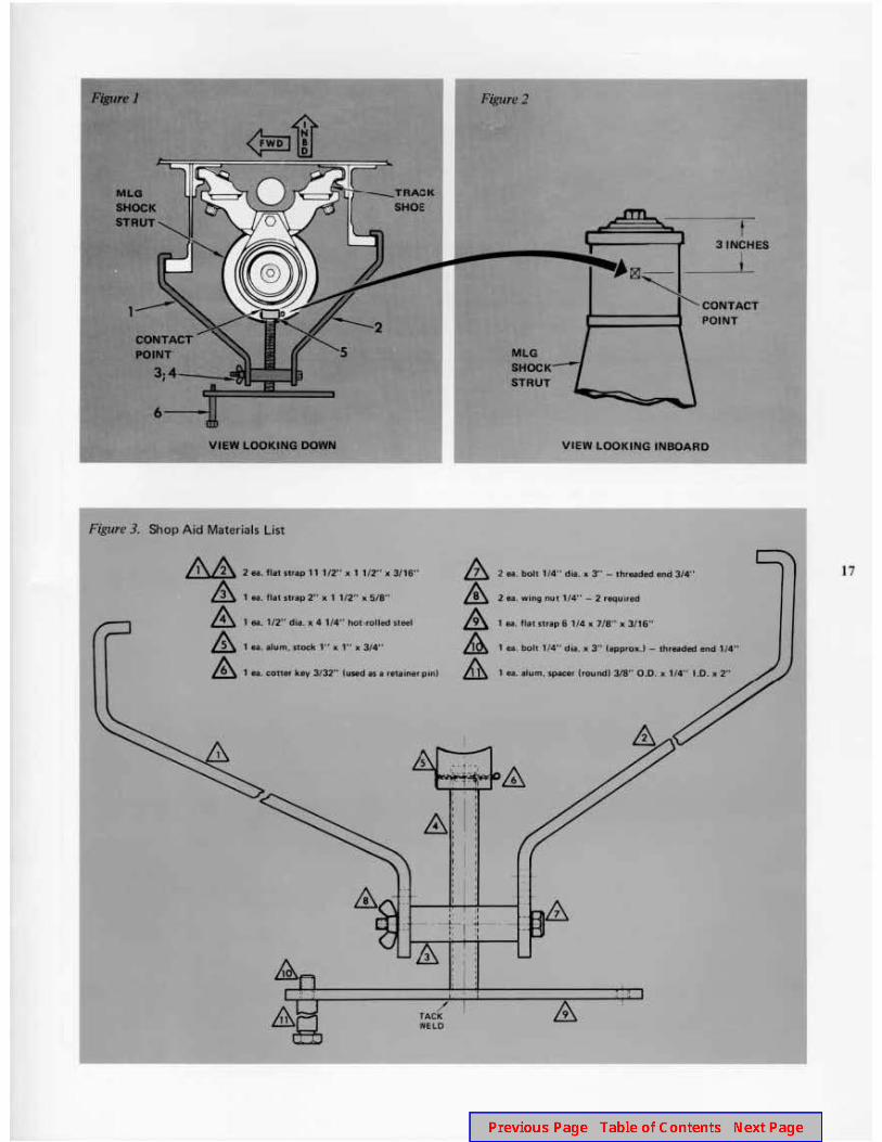
The proper operation of the Hercules aircraft mainlanding gear (MLG) requires proper adjustment andmaintenance of the MLG shoes.
To adjust or replace the upper MLG shoes, it is necessaryto loosen or remove the upper track shoe attachmentbolts. When these attachment bolts are loosened orremoved, the strut can move outboard enough to causebinding of the shoes against the tracks. A shop aid hasnow been designed that can relieve pressure on the trackshoes.
The shop aid is used to position the shock strut so thatthere is no pressure against the shoes while the trackshoe attachment bolts are loosened or removed duringmaintenance. This should make MLG shoe adjustment orreplacement easier and faster.
Using the Track Shoe Shop Aid
16 The track shoe shop aid (Figure 1) is used in the follow-ing manner:
Jack the aircraft following instructions in the ap-plicable maintenance manual.
Place the tool’s flanged arms (1 and 2) over the for-ward and aft vertical beam flanges of the selected MLGshoe track assembly. See the example in Figure 1.
Close the shop aid’s flanged arms (1 and 2) bytightening the wing nuts (3 and 4) of the threaded blockthru-bolts.
Position the shop aid so that the screw jack contactblock (5) is at least 3 inches from the top of the MLGshock strut (Figure 2).
Hold the shop aid in position by turning the screwjack handle (6) clockwise until the flanged arms and con-tact block are securely in place.
Shoe centering is accomplished by turning the screwjack handle clockwise to relieve the pressure betweenthe outboard face of the shoes and inboard face of theshoe tracks.
With the upper track shoes held in the center of thetracks, the track shoe attachment bolts may be loosened
or removed as necessary to carry out the required main-tenance activity.
Remove the shop aid by turning the screw jackhandle counterclockwise, then loosen the thru-bolt wingnuts.
Repeat the preceding operation as required to com-plete track shoe maintenance of all MLG upper trackshoes.
Note
1. The shop aid will fit either the forward or aft MLGshock struts. Just rotate the tool 180” as required.
2. In Figure 4 (item 1A and 2A), multiple sets of holesarc shown. The extra holes permit adjustment of thetool to tit various MLG vertical beam configurations.
We believe that the use of this tool can save significantamounts of time and money when MLG track shoe main-tenance is required. If you are interested in acquiring thisuseful new tool, please contact your Lockheed-GeorgiaService Representative or Lockheed-Georgia Logistics,Dept. 65-11. Specify Lockheed Part Number 3402799.
The following list of construction materials and drawingsshould be helpful for those who prefer to build their ownshop aid.
MLG track shoe shop aid in use.
6·---VllW LOOICIN8 DOMI
Figure J. Shop Aid Materials Llsl
&& 2 U. ftM: IV• 11 1/2'0 x 1 1/2"• lll 3(11"
& , ... flat 11rap r • 1 112" • 511··
& 1 a 1/2" ltiiL X. 11• " hOl<fOIJed tt911
& 1 • · .iurn. flodc 1'' lit 1'' • 31.t"
& 1 • con. by 3132"' tined•• r.ui'* p1nl
5
' ' & :
fACIC WiLD
' I ' I I I
' t ' " I .. .I
llLG mtOCK STRUT
I 3 1NCHES
I
CONTACT POINT
VIEW LOOKllllG lllllOARD
2 M . boh 1 /4 " die. • 3" - thruct.d ..,.. 314"
2 ... wing nu1 114" - 2 requlrld
1 N Ult 11RP 6 1/4 • 1/1 .. a 3/1&"
, .. bolt 1/4" d'- • 3" 1.,..0. J - thfelUd end ,, •••
1 • .tum,...,.. troul'dt 311 .. 0 .0 . • 1/t" 1.0. 11 2 ..
&
9
17

18
~
f g
~ .. <
l 0
!i 0 z
I I
-;. ' \ " '!.. =· .
• 0 ~ - - ~ - ~ - ~ ' .. !!
'' @1]' ~ - -- ~
u.
~ I ~ . ~ 0 ~ <t
C I ti; E. - - ~ - -1 k .. 0
r - ....
1,...., ..... ------..... -p-------.......... l ............ ______ _,__..._ ______ ...i....&.1
~ I ~ .. _,
I ;{ 1--w 0
. ~ -
;; • I
" ' "' .. -~ ;;1 !> ... +-~ l ' -~
<>-I - ;: -
~ -- -- - - -..
T
~
~<9 % u. - 0 0
" :> _,
= <t t;; "' 0
Figurl! 4. Conuruction plans for MLG trick shoe shop aid.
~ u. 0 _, < 1--w 0
T b
~ ~~ ~L.L.J~~ u. 0 _, ~ w 0

The wives of several Sudanese Ah Force personnel recent-ly visited facilities of Lockheed-Georgia, where Herculesaircraft similar to those operated by Sudan are being built.The visitors toured the production floor, the fligbt line,and the training classrooms. The ladies were in the U.S.to spend some time with their husbands, who have attend-ed Lockheed classes for the past 11 months. The couplesvisited local points of interest, and were treated to localhospitality. Most of the wives returned to Sudan after aone-to-three-month stay.
19
In the “Shock Strut Servicing” article that appeared inV7N3, there is an error on page 13. Photograph B shouldshow the “X” distance as being the distance between theupper and the lower torque arm bolts (photo at right),rather than the distance between the lower torque armbolt and the torque arm disconnect bolt.

CUSTOMER SERI/ICE 0 11/ISION LOC~HEEO-GEORGIA COMPANY .., 0.l't11'910N Of LOC!IJ'41.ID CO•llO•AflO-. MA .. llTTA OlOAIJIA 30C1R
STICK IT IN YOUR EAR
Wear ear protection protect your hearing
When your work assignment requires extended exposure to hi~ noi• lav·
els, always Ul8 proper ear protection to prevent .-rmanant hearing loss.