Embed Size (px)
Citation preview
µ Notes
Vol. 5 No.1 July 2005
A Publication of the
State Microscopical Society of Illinois
EDITORIAL
This is the first publication of µ Notes since µ Notes Volume 4, No. 1, 2003. In keeping with the current times, both electronic and economic, µ Notes now resumes publication in an online PDF format. As a result, SMSI can: • publish color images at no cost • allow for thinking beyond the four-page
multiple block in conventional printing • publish articles in a more timely manner • be unrestrained by the number of articles and
pages • save on mailing expenses. Also, past issues of µ Notes from its inception in 1872 (as The Lens) to the present will be available in the future. This is a noble / ignoble goal…to catch up on 133 years of history. What gave impetus to this project was the open letter to SMSI, which surfaced on June 26, 2005, from Gilbert Hartley on his acceptance of the1994 SMSI award, who ironically passed away at the beginning of June, 2005. This letter, with Hartley’s anecdotes demon-strating his wry sense of humor, presents a history of men, microscopy, and science. (All British English spelling is retained.) Also appearing in this issue of µ·Notes are articles submitted by Mickey Gunter (modified from extraLapis English with permission granted to SMSI) and by John G. Delly. SMSI has many reasons to remember Gilbert Hartley with this first on-line edition of µ Notes—his wit, his life-long work, and his pushing SMSI into the 21st century. Bill C. Mikuska President, SMSI
µ Notes Volume 5, No. 1, July 2005
Bill C. Mikuska
Editor
Joseph Barabe Assistant Editor
Dorothy Mikuska Managing Editor
µ Notes is a State Microscopical Society of Illinois publication. Its purpose is to provide a form of communication between amateur and professional microscopists, to share ideas and techniques, to ask questions, to obtain answers, to express opinions, and to publish results of experiments and research. It will also provide space for members to print wanted and for-sale notices of microscopical equipment. All opinions expressed by contributing authors of µ·Notes are the responsibility of the author(s) and do not necessarily reflect the opinion of the State Microscopical Society of Illinois or that of the editor. Contributions should be addressed to EDITOR, µ Notes, 3005 Avenue Loire, Oak Brook, IL 60523, [email protected].
µ Notes © 2005
State Microscopical Society of Illinois
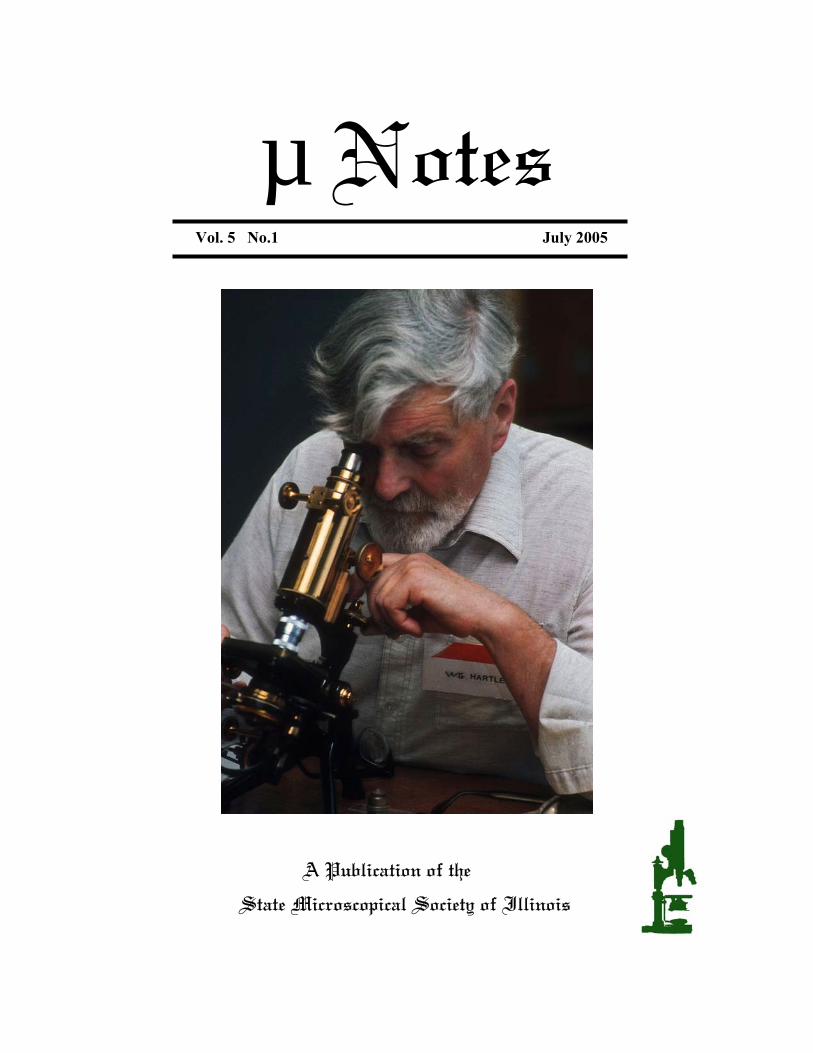
Cover: Gilbert Hartley, photo courtesy of Peter Evennett, Leeds University and RMS
CONTENTS VOLUME 5, NO. 1, 2005
Acceptance Letter from Gilbert Hartley to SMSI 1 A Lucky Break for Polarization: The Optical Properties of Calcite Mickey E. Gunter 8 Principles of Micromanipulators and Micromanipulation: A Mid-Century SMSI Lecture-Demonstration-Workshop John Gustav Delly 19 SMSI President’s Report: July 2004 – July 2005 Bill C. Mikuska 45 2005 SMSI Emile Chamot Award Recipient Dr. Osamu Shimomura 48
µ NOTES JULY 2005 1
Acceptance Letter from Gilbert Hartley to SMSI
The text that follows comes from Gilbert Hartley’s letter and retains the original British spelling. Originally, this was the text of a video tape he sent to SMSI that accompanied the video tape which was his acceptance address to SMSI for receiving his award in 1994. This lasts about 30 minutes. Chicago text. GH 4-4-94 Mr. President (then Joe Barabe) and Officers of the State Microscopical Society of Illinois and Members and Guests, whom I am most unfortunately not in a position to see personally, but for all of whom I have the highest regard, I trust that you will forgive me for appearing before you by proxy (video tape) on this prestigious occasion. As I have made clear to your President and to Mr. Martin L. Scott, my physical abilities were never designed to last as long as they have had to, and it has become apparent even to me that what I can do and what I imagine I can still do are quite distinct. And I have a sneaking suspicion that my mental abilities are equally threadbare. You will form your own opinion about that. My appreciation of the great honour you confer on me is only tempered by a sense of bafflement that you should imagine me to be a suitable subject for it; I trust that you will accept my thanks for that privilege, and my apologies for my physical absence. We have a cynical maxim - "Those who can, do; those who can’t, teach," Perhaps it may help to explain my pretence of being a microscopist if I run through the sequence of events which has led me to it. To make it look authentic, we can treat it under the title:
ASPECTS OF MICROSCOPIC LIFE by
WALTER GILBERT HARTLEY B.Sc., M.I.Biol.
Honorary F.R.M.S.
I was born on the last day of 1913, the final year of European civilization, and spent my first eight years in a large house with a very large garden in south London, where my father ran his business as a yeast merchant. It was crammed with everything a solid Victorian family ought to have available, and my interest in microscopes developed there at the age of six. I say microscopes rather than microscopy as a matter of principle, because microscopy is a subject so multifarious that different specialists can scarcely recognise each other's fields. I have said somewhere or other that microscopy is like the North Pole - all the lines of enquiry run through it, but none stops there, and the only folk who stay there are freaks like me who want to find how high it is; the others go on to do something useful elsewhere. My fascination began when my father, probably in a state of desperation, because I remember asking him how the Egyptians in the desert could suffer what the Bible called "divers' diseases", which I assumed to be the bends, laid the square of green baize on the thick table cloth, took from a hitherto mysterious mahogany box the brass microscope which had belonged to his brother, swung the gas light low over the table, and showed me some of the prepared slides. An old Scottish lady once remarked that it was a great comfort that at the Day of Judgment the truth would be known about
GILBERT HARTLEY
µ NOTES JULY 2005 2
the Gowrie Conspiracy (which had occurred in 1600). I feel much the same about that microscope. I have spent my life vainly trying to discover its maker. Quite recently my niece turned up in one of my grandfather's account books the record that he had paid £6”7”6 (about $33 then) for the instrument to a Mr. H. I. Beech of Peterborough early in 1882, and £3”15”0 ($18) for a 1/8” objective to the same man a month later. I have not managed to run the vendor to ground; his name means nothing to local historians, and it is possible that he was someone privately known to my grandfather. Anyway. the instrument has an eight inch body with an idiosyncratic bore and straight-cut rackwork. James Swift had introduced spiral racks the previous year, and I have always associated him with the stand because it has the Wale suspension which he favoured, though the redoubtable James, who made Thomas Powell's last microscopes, would surely never have hung the stage on two screws set so close together, firm though it is. The stage is a black glass disc in a narrow brass rim, with a gliding slide carrier, a type favoured by some makers at that period. I have wondered whether it might be an American import, but it did not ring any bells with the authorities in Washington. Its really original feature is the fine adjustment, a side micrometer screw moving an entire inner body inside the outer tube. This is unique in my experience, and remarkable in being so arranged that the action would drive the objective through the slide instead of lifting it against a spring. Perhaps IT Beech made it himself; there is not a vestige of a name on the stand or any of the lenses. There are three objectives. in boxes with engraved figures. The 3/4” and 1 1/2” lenses are not obviously designed to separate. and the less said about the 1/4” the better. Both have the R.M.S. thread, but are slightly oversize. The 1/8” is an entirely different kettle of fish. It is a very good lens of 0.85 N.A., highly finished, and with its front lens
in a tube sliding on the main body. The thread is exact. I keep thinking I can recognise the maker, but this is stupid, as one man supplied most of the high-power objectives to the trade at the time. Of course, the 1/8” is not really practical on a stand with no substage condenser - or am I being toffee-nosed? A lot of work was done on stands without them - Heaven knows how! My Uncle Walter, a budding pharmacologist who died young, got his medal for Materia Medica, so it may have helped him. My father died in a flu epidemic at Christmas 1921, when I was just short of eight, and we moved out of London. I had discovered in the house the three Victorian oracles - Half Hours with the Microscope, Common Objects, and A Thousand Objects for the Microscope, so someone must have taken an interest, but I am lamentably short on family tradition. We moved again, in 1927, to the New Forest, where the life in the local ponds entertained me, but I was not interested in identifying the targets of my observation; the fact that I could recognise to some extent the kind of animalcule at work on the slide satisfied me, and I liked to turn them loose afterwards to get on with their lives. My interest lay in actually being able to see the things clearly. I was fortunate in being sent to a grammar school in Winchester which enjoyed a Headmaster who was a scientist. We split between science and literary studies at 14; according to legend the two masters most concerned tossed for me, and the math master lost and was saddled with me. In due time I reached the sixth form, where we spent our time on math, physics and chemistry at great intensity, and one of my classmates became a Bachelor of Science before leaving. The school has provided the Royal Microscopical Society with two Honorary Fellows and a President, which is not bad for one establishment. Biology was not taught in boys' schools then, but I learned the basics of microscope handling
GILBERT HARTLEY
µ NOTES JULY 2005 3
from a book in the school library; unfortunately I failed to recognise blatant commercial propaganda in disguise. After leaving I went as Student-Assistant to the Professor of Zoology and Geology at what was then University College, Southampton. It had been the Hartley Institute in earlier years, specializing in MiddIe Eastern studies; the University is now a highly respected institution, but it has come a long way since my time. I met Quekett's Treatise and Spitta's Microscopy in the departmental library, but microscopy was regarded as a necessary evil. The Professor had in his study a top quality Watson instrument; in three years I never saw it out of its bell-jar. In the laboratory we had Watson Kimas and two small Leitz microscopes, one of which I annexed for my personal use and fitted with an Abbé Illuminator surreptitiously taken from a Spencer microscope in the Botany Department, where they did not appreciate such refinements, and voted them a nuisance. It had a lateral slot to carry filters, and I made a darkground stop (which I still have) out of a piece of celluloid from the sidecar windscreen of the Ace I used to ride then. I never managed to persuade the Prof that I had not myself invented darkground illumination, and he never forgave me for doing so. It was a curious training. The Geology lecturer had no students, so I took the course out of interest. Petrology involves polarized light, which to my mind provides the very finest training in microscopy and is a great brain-sharpener. I do not pretend to competence in mineralogy; I say of my expert friend that while we both speak the same language, he knows what the words mean. I graduated in Zoology. Geology and Botany, but jobs were very scarce in 1935; nobody wanted geologists in those days. After waiting nine months I unexpectedly found a niche in Scotland, continuing a migration experiment stalled in 1920, tagging salmon in the sea off the north-west coast. The job was hard and instructive, and lasted for three years - until the war put a stop to it. In summer I ran the small fishery,
and over the winter read the scales I had collected and wrote my reports in Edinburgh. Salmon Fisheries was a kind of private kingdom in those days, with very little contact with the rest of the Fishery Department, and with its own two-room laboratory a mile away from headquarters, up four flights of stairs and looking across the valley to Edinburgh Castle. As there was no money for research, we concentrated on studying population statistics by reading salmon scales collected at fishing sites, which cost nothing and did not need special treatment, being just wiped off the knife into envelopes and stored dry. They were spread half a dozen at a time on a slide, covered by another, and projected onto a vertical screen on which the proportional lengths represented by the winter bands were marked off on strips of card and measured against a piece of graph paper glued to a board. I believe that it has been found possible to complicate the process now. The scales were projected on a Zeiss optical bench five feet long, with a microscope at sight of which the Zeiss rep was reputed to have fainted. It was a Madel 4 dating from about 1880, projecting the image horizontally. I bought one recently, "for the sake of auld lang syne." It was lit by a large Zeiss Punktlampe with a collector lens, and a Köhler lens half way along the rail, but the microscope had no condenser. After suffering for a time, I went to Woolworth's and bought a watchmaker's eyeglass and some adhesive tape and supplied the missing component, to general satisfaction. It was difficult to project a useful image of a scale a centimetre wide - a flat and entire image - through a narrow-bodied microscope; after two years I managed to persuade the Department to spend £7”10 (say $30) on a microscope with a wide barrel, and sat back in relief - and then the coming war put all our work on hold. I returned to the New Forest and wrote my last report at home. I also bought a second-
GILBERT HARTLEY
µ NOTES JULY 2005 4
hand Watson microscope with a centring substage out of the first money I earned as a consultant, £20 in a pollution case. As I had the choice of a Zeiss Jug-handle at the same price, I can only blush at my susceptibility to Watson's ubiquitous propaganda. When war broke out, I found myself to my dismay too old at 25 to enter the service I wanted to join, or the next best, but this was probably a blessing in disguise, as in quick time I was ordered into the Mine Design Department of the Admiralty. It is still my contention that two dug-out admirals scanning the Scientific Register decided that a man with a Degree in geology must be familiar with mines. I was the first civilian injected into the Department, followed not long after by a man from the Board for Safety in Mines and another misfit. In due course I found myself back on the west coast of Scotland, in the Firth of Clyde, and by the end of the war had acquired a proficiency in hydrographic surveying and coarse electrical engineering - our motto was "Switch on and chance it!" It is quite remarkable how all this disjointed experience could suddenly gel and set one up for quite a different problem. By the end of my career I had become a genuine expert on electrical methods of guiding fish. In the meantime I experimented on producing contrast between the various organs of marine invertebrates by mounting whole specimens in various media. When the war ended I found myself in the Royal Naval Physiological Laboratory, alongside the cemetary of Haslar Naval Hospital across the harbour from Portsmouth, and once again concerned with Divers' Diseases. It was quite inevitable, as I knew no physiology - when as students we had pointed out the lack of any physiology in the programme, although we should be examined in it, the professor had snapped decisively "If ye wanted pheesiology ye sud hae gane tae a pheesiology deparrtment - here we do zoology." That was that. He abominated any mixture, and Prof. Hogben
was his bête noir for combining the two - "He spoilt the Chair at Capetown." Microscopically speaking, my time at R.N.P.L. was climactic. In 1946 we could look up from our recent preoccupation and take in what had been happening abroad. There were shiny new American books, German research reports and workers to interrogate, new ideas – “phase contrast" seemed to be the new elixir - and we had plenty of plans for exploiting them. We had in fact everything but space and money. The eight of us occupied a very small cottage which periodically leapt into the air when my former colleagues carried out a trial in Spithead, and we kept our dinghies moored to the garden fence. We had all brought our own apparatus because there was no more to be had commercially for love or money; we built our own E.E.G. machine, and did notable work in our constricted quarters on the physiology of diving. I was concerned with alterations in tissues caused by stress, and looking for any means of displaying it. We had the pieces of a vast ultra-violet microscope system in the stables - a terrifying thing like a big bass drum, with large cadmium wheel electrodes driven by three-phase motors, and capacitor banks with the explosive quality of grenades, which probably took its revenge on me years later - and also, more usefully, two devoted ex-submarine artificers who made every kind of device we invented. I was interested in this fabulous phase contrast business. The Assistant Secretary of the R.M.S. lent me copies of two papers by Bennett, Jupnik, Osterberg and Richards. These baffled me initially because I could not conceive how a feature differing in refractive index from the ambient medium could possibly be made invisible, nor imagine producing a quarter wave retardation except in polarized light. I have always been proud of the fact that within a week I had realized how to make a polarized light system which would produce a variable phase contrast. In principle it was obvious
GILBERT HARTLEY
µ NOTES JULY 2005 5
that if the diffracted rays from an object were polarized in a plane at right angles to the direct ones, I could slide them into any mutual relationship by using a standard compensator, and adjust their relative intensities also. The catch lay in actually doing so. Academically the obvious method involved a phase disc made of right- and left-handed quartz, but that was out of the question for me; in the Chinese maxim, I had to learn to itch where I could scratch. I had to learn how to make suitable components from materials I could both obtain and also work with ordinary hand tools. I always enjoy having to improvise, but I am far from being an adept. I had pieces of mica from a broken stove window, and managed to construct discs with a �/2 mica annulus mounted in some concoction - not piperine, which was desirable but unobtainable. Later I used selenite, which was easier to handle, from a Victorian microscope slide. Thin films of Polaroid could be extracted from the type available then. In those days we had a restricted range of plastics, liable to be discontinued at any moment, so that discs could not always be duplicated, and it was essential to keep every scrap of whatever one could lay hands on. (It is hard to shake off this habit.) I published a letter in Nature describing my Variable Phase Contrast System, with photomicrographs showing the result. It drew a claim for priority from France, and was noticed in the literature, but raised no excitement. In recent years, it has been patented in Japan as an interference system, which it is not - it modifies the relationship of light waves after diffraction by the specimen; actually I could have produced the same effect with a normal phase contrast objective (had one been obtainable) by working at different wave lengths, but I did not think of that at the time. My work had also led me to experimenting with variable high power dark ground and Rheinberg systems. It was obvious that by using polarized light it was possible to obtain a very flexible interference effect,
and I was experimenting along these lines when Francis Smith at Chas. Baker Ltd. produced what I was hunting for, and the Polanrett microscope was described by Harold Osterberg of the American Optical Company. It was clear that the idea was in safe and far more competent hands than mine, and there was no point in extemporizing. In addition, I discovered to my amazement that there was another Gilbert Hartley in Britain, also working on microscope interference systems. Some coincidences are more compelling than others. It was just at this time that I had realized that my happiest hours had been spent in an open boat tagging salmon ten years earlier. The war was over, and the urgent problem was producing food. The Admiralty had let me out on a string in 1945 to help Gavin Maxwell when he tried fishing for basking sharks, as I knew as much about them as anyone at that time. In 1948 the English Ministry of Agriculture & Fisheries decided to continue our old Scottish salmon migration experiments. I went to see them, and re-entered fishery work. This was a disaster; if I had not been so forward, I could have returned to the Scottish department, which advertized shortly afterwards, and my wife and daughter could have remained in our home on the west coast of Scotland instead of moving south to London, which we all loathed. (The veterans used to warn us never to volunteer for anything!) The London laboratory looked across the road at Big Ben and shook like a jelly when the underground trains stopped and started in the station below, so that it was impossible to use my scale projector in the rush-hour. I had spent odd hours during the war designing the perfect scale-reading projector, and had now constructed it - as usual, with ludicrously inappropriate tools, and from whatever I could lay my hands on. It had a rotating horizontal stage so that the scales could always be seen in the same orientation, and would not fall out just when I was on the point of measuring them. This
GILBERT HARTLEY
µ NOTES JULY 2005 6
was mounted in the propeller bearing of a Whitby crab boat; the viewing screen was at right angles to my normal line of sight, and the measurements were made with a cursor and read from a galvanometer spot. The focusing mechanism was a Beck substage, with no constricting tube, illumination was by a mercury vapour lamp and suitable lenses, and the whole was built around a typing table which housed everything relevant. I always maintain that it was having bored a hole in a typing table which damned me officially. The projector was described in the R.M.S. Journal and that of the International Council for the Exploration of the Sea, and worked admirably for years until the table disintegrated. I was going to make another with a steel table and digital voltmeters for the read-out, but time caught up with me. I was too much involved with electric fishing and fishway design to do it myself, and my assistants always had excuses; they were electronic wizards who knew nothing about optics and were determined to remain uncomplicated. Inevitably I had been concerned with fish pathology, and spent awful hours studying the specimens sent in by the public. It is axiomatic that no-one realizes a fish is dead for the first two days, and there are few more reticent corpses than a dead fish sent through the post over the week-end. I had long been interested in water-immersion objectives, and had suggested that when dealing with wet specimens, there is no logic in using oil, and that water immersion has considerable merits. What puzzled me was that nobody offered a water-immersion phase objective, which would be ideal for studying the protozoan fish parasites which afflicted me. I persuaded Cooke Troughton & Simms Ltd. to put into their 1.0 N.A. water immersion objective a phase disc congruent with the one in their 100:1 oil immersion. The lens has proved ideal for its purpose, and I am amused to see that water phase objectives of medium power are now listed by European makers. I do not suggest that a water-immersion can replace an oil-immersion, but that a good view of a live
specimen moving is much easier to identify than a shapeless stained blob. I was elected to both the Royal Microscopical Society and also the redoubtable Quekett Microscopical Club when I came to London, and was soon dragooned into providing abstracts of foreign papers and reviews for the Journal of the R.M.S. and lectured in the instructional courses from their start in 1963 until I had to give up after falling off a jetty a few years ago. I also became a practically permanent fixture on the R.M.S. Council within a few years; I believe I hold the long service record. It was in that capacity that I came into personal contact with United States microscopical personages. We had a centenary to celebrate. The Society had been founded on 3rd September 1839, but the centenary fell on a Sunday, and we waited for the centenary of the granting of the Royal Charter in 1966 and had a party then. At the banquet I was seated next to the President of the New York Microscopical Society, and everything went very happily until I noticed one of the waiters - I do not know where the catering company found them - idly supporting a wine bottle by his finger inside the neck while looking for customers. I was determined that he should not get anywhere near us, or anyone I could signal without causing panic, and hoping that my companion would not notice the oaf, when she gasped out, "Don’t you British believe in the germ theory of disease?" I assured her that, on the contrary, we regarded the ingenious speculations of M. Pasteur with the utmost admiration, but the situation was saved by a note from our own President calling on her for "a few words" when he dried up. This treacherous blow distracted her and we had to cook something up in haste. I had suffered it myself, and could therefore prime her with the tale of the Christian and the lions, which gives one time to extemporize, and she came through with flying colours.
GILBERT HARTLEY
µ NOTES JULY 2005 7
Books on microscopy are very numerous but often unhelpful, as the author writes to confirm what he already knows, and feels obliged to pad out the text with stuff which he has no interest in. I had written a students' book myself in 1962 for English Universities Press, which had been meant to clear up practical points which everyone else fought shy of. It seems to have been found helpful. I had to revise the original book when I retired at the end of 1975, and started on a new one - at the publisher's request, not out of vainglory. Publication of both books was delayed for several years for various reasons, and I had to keep revising them - a horrible chore, in which one is haunted by the ghost of Jabez Hogg, whose book ran through fifteen editions between 1854 and 1911 and always contrived to be a generation out of date. I can only say with the cabbie who failed to reach the station in time with me after an air raid "I done my best!" Thank you.
µ NOTES JULY 2005 8
A Lucky Break for Polarization:
The Optical Properties of Calcite
This article first appeared in the Calcite issue of extraLapis English, No. 4, 40-45 (2003) and is reprinted here slightly modified with their permission.
Mickey E. Gunter
Department of Geological Sciences University of Idaho
Moscow, Idaho 83844-3022, U.S.A. [email protected]
Introduction
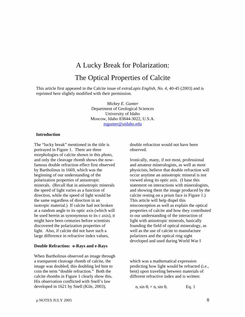
The “lucky break” mentioned in the title is portrayed in Figure 1. There are three morphologies of calcite shown in this photo, and only the cleavage rhomb shows the now-famous double refraction effect first observed by Bartholinus in 1669, which was the beginning of our understanding of the polarization properties of anisotropic minerals. (Recall that in anisotropic minerals the speed of light varies as a function of direction, while the speed of light would be the same regardless of direction in an isotropic material.) If calcite had not broken at a random angle to its optic axis (which will be used herein as synonymous to its c axis), it might have been centuries before scientists discovered the polarization properties of light. Also, if calcite did not have such a large difference in refractive index values,
double refraction would not have been observed. Ironically, many, if not most, professional and amateur mineralogists, as well as most physicists, believe that double refraction will occur anytime an anisotropic mineral is not viewed along its optic axis. (I base this statement on interactions with mineralogists, and showing them the image produced by the calcite resting on a prism face in Figure 1.) This article will help dispel this misconception as well as explain the optical properties of calcite and how they contributed to our understanding of the interaction of light with anisotropic minerals, basically founding the field of optical mineralogy, as well as the use of calcite to manufacture polarizers and the optical ring sight developed and used during World War I
Double Refraction: o-Rays and e-Rays When Bartholinus observed an image through a transparent cleavage rhomb of calcite, the image was doubled; this doubling led him to coin the term “double refraction.” Both the calcite rhombs in Figure 1 clearly show this. His observation conflicted with Snell’s law developed in 1621 by Snell (Kile, 2003),
which was a mathematical expression predicting how light would be refracted (i.e., bent) upon traveling between materials of different refractive index and is written: ni sin θi = nr sin θr Eq. 1
MICKEY E. GUNTER
µ NOTES JULY 2005 9
Figure 1
Photograph of three morphologies of calcite, and light propagation through them. The rhombs show the case of well-known double refraction, where the o-ray (i.e., the ordinary ray) obeys Snell’s law and the e-ray (i.e., extraordinary ray) does not. The bottom rhomb also has sheet of polarizer (long axis of sheet is polarization direction) laid on top to show the polarization direction of the e-ray and o-ray and how the double image of the straight line is made into a single line after passing through the polarizer. For the basal morphology, the view is down the c axis and the light remains unpolarized. For the prism morphology, the c axis is parallel to the page, and light passing through the crystal would be forced to vibrate along either the ω or ε vibration direction. Note, in this orientation that even though the light travels along two separate vibration directions, the classic double refraction does not occur and both rays are o-rays by definition. (These samples were provided by Carl Francis, Harvard Mineralogical Museum and Anthony Kampf, Natural History Museum, Los Angles.)
MICKEY E. GUNTER
µ NOTES JULY 2005 10
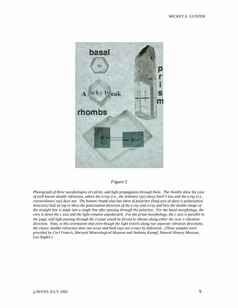
where ni = refractive of the incident ray, θi = the angle of incidence as measured from a normal to the surface (Figure 2), nr = the refractive index of the refracting media, and θr = the angle of incidence of the refracted ray. Recall the refractive index of a material is the ratio of the speed of light in it divided by the speed of light in a vacuum, which will be greater than 1.0, because as the photons of a light beam interact with the electrons of a material, they are slowed. The greater the interaction, the higher the refractive index. Figure 2 shows the results for ray 1 with an angle of incidence of 45°, and traveling from air into a piece of glass. The precise angle of refraction can be calculated from Equation 1. One can observe that when a light ray travels from a material of lower to higher n, it is refracted toward the normal of that surface (Figure 2, as ray 1 enters the glass), and when it travels from a high to low n, it is refracted away from the normal (Figure 2, as ray 1 leaves the glass.) However, for a ray at normal incidence, the case of ray 2 in Figure
2, no refraction occurs and the light travels straight through the material undeviated in direction, although it would be slowed. Based on Snell’s law, only be one image should be produced when light is normally incident on a transparent material. However, a calcite rhomb produces two images (Figure 1), clearly in violation of Snell’s law. Note neither the basal nor prism morphologies produce two images; the reasons why will be discussed later. Based on this discrepancy with Snell’s law, Bartholinus chose to call the ray that obeyed Snell’s law the ordinary ray, abbreviated as o-ray, and the ray that did not normals and not ray paths obey Snell’s law as the extraordinary ray, or e-ray. These terms have evolved into the refractive index values for the uniaxial class of minerals, ω and ε. However, as we will see later in this article, both ω and ε are really o-rays. We will also see that Snell’s law is not really violated if one considers the polarization characteristics of the light and reinterprets of Snell’s law by using wave normals and not ray paths.
The Discovery of Polarization The explanation of double refraction in calcite became a major goal of the scientific community. In 1807, the French Academy of Sciences offered a prize for anyone who could explain the phenomenon. Malus sought to claim the prize (Kristjansson, 2002) but instead discovered polarization by reflection of light while studying calcite. He coined the term polarization. However, it appeared to be Fresnel and Arago (Bloss, 1999) who realized calcite polarized light. In
fact, they showed that the o-ray and e-ray were polarized at right angles to each other. This effect is seen in the larger rhomb in Figure 1 by placing Polaroid sheets atop it. The sheet on the left shows the e-ray, and the one on the right shows the o-ray. (The sheets only allow light polarized along their long dimension to pass.) Notice the double image of the line in the center of the rhomb becomes a single image when viewed through the sheet polarizer.
The Interaction of Unpolarized Light with Calcite Three orientations (i.e., directions of travel) are of interest for an unpolarized light beam entering a calcite crystal: 1) normal to a rhomb face, luckily the most common, 2) normal to a basal section (i.e., parallel to the optic axis), and 3) normal to a prism face
(i.e., normal to the optic axis.) All of these i.e., normal to the optic axis.) All of these orientations are shown for natural crystals in Figure 1, and sketches of each, showing light paths, are shown in Figures 3 and 4. The rhomb face is the more general case where
MICKEY E. GUNTER
µ NOTES JULY 2005 11
Figure 2
Ray tracing through a block of glass showing the angular relations based on Snell’s law. Ray 1 is incident on the block of glass at the angle θi and is refracted to the angle θr after passing into the glass. Notice that when a ray travels from a less to higher refractive index material it is bent toward the normal of that interface, and it is bent away from the normal when it travels from high to low refractive index. Ray 2 is normally incident on the glass, and this undergoes no refraction. the light does not travel parallel or perpendicular to the optic axis.
When unpolarized light enters normal to the rhomb face, it is broken into two mutually perpendicular polarized rays, the o-ray and the e-ray (Figure 3). The o-ray proceeds undeviated through the sample with its polarization direction perpendicular to the optic axis. The e-ray vibrates in the plane of
the optic axis and parallel to the rhomb face. Upon emergence from the crystal, the o-ray and the e-ray are thus offset, producing two images polarized perpendicular to one another. Explanation of the separation of these images (i.e., double refraction) led to the discovery that calcite, and all anisotropic minerals, have the ability to polarize light. For a basal section of calcite (Figures 1 and 4), the normally incident light would travel along the optic axis. By definition, the optic axis of a uniaxial mineral is perpendicular to its circular section, and the circular section has the same refractive index in all directions, thus behaving like an isotropic mineral. For this orientation the unpolarized light remains unpolarized after passing through the crystal. A similar but slightly different phenomenon occurs when light is incident on a prism face (Figures 1 and 4). Again, no double refraction occurs, but in this case the incident unpolarized light is polarized during passage through the crystal. If these were the common forms of calcite, double refraction would have not been discovered, at least in calcite, until someone cut the mineral at a random angle to the c axis. Double refraction will occur only in such an orientation, not only for calcite but for any uniaxial mineral.
Snell’s Law Is Not Broken In Figure 3, the “side view” of calcite has an extra ray labeled “WN” (wave normal). The wave normal is the direction perpendicular to the vibration direction of polarized light. Notice the WN for the e-ray would pass undeviated through the calcite rhomb, thus obeying Snell’s law. So if Snell’s law had been defined based on wave normal and not ray paths, it could have been applied to any
direction in an anisotropic mineral. Snell’s law was derived for light passing through isotropic media, and calcite, when broken on the rhomb face, appeared to violate this law. Again, if calcite did not cleave on the rhomb face, this apparent violation of Snell’s law (as defined by ray paths) may have never been observed.
MICKEY E. GUNTER
µ NOTES JULY 2005 12
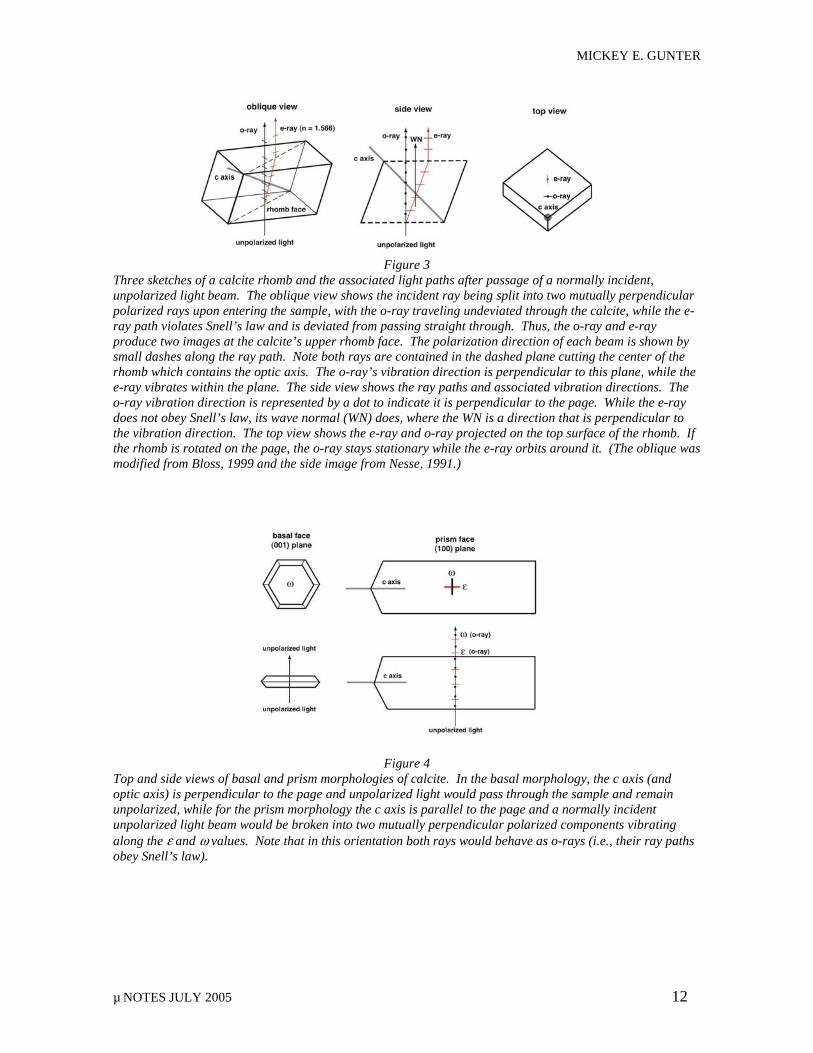
Figure 3
Three sketches of a calcite rhomb and the associated light paths after passage of a normally incident, unpolarized light beam. The oblique view shows the incident ray being split into two mutually perpendicular polarized rays upon entering the sample, with the o-ray traveling undeviated through the calcite, while the e-ray path violates Snell’s law and is deviated from passing straight through. Thus, the o-ray and e-ray produce two images at the calcite’s upper rhomb face. The polarization direction of each beam is shown by small dashes along the ray path. Note both rays are contained in the dashed plane cutting the center of the rhomb which contains the optic axis. The o-ray’s vibration direction is perpendicular to this plane, while the e-ray vibrates within the plane. The side view shows the ray paths and associated vibration directions. The o-ray vibration direction is represented by a dot to indicate it is perpendicular to the page. While the e-ray does not obey Snell’s law, its wave normal (WN) does, where the WN is a direction that is perpendicular to the vibration direction. The top view shows the e-ray and o-ray projected on the top surface of the rhomb. If the rhomb is rotated on the page, the o-ray stays stationary while the e-ray orbits around it. (The oblique was modified from Bloss, 1999 and the side image from Nesse, 1991.)
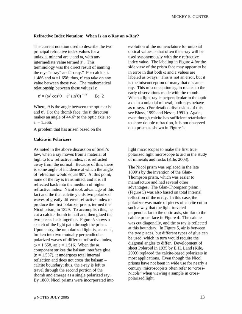
Figure 4 Top and side views of basal and prism morphologies of calcite. In the basal morphology, the c axis (and optic axis) is perpendicular to the page and unpolarized light would pass through the sample and remain unpolarized, while for the prism morphology the c axis is parallel to the page and a normally incident unpolarized light beam would be broken into two mutually perpendicular polarized components vibrating along the ε and ω values. Note that in this orientation both rays would behave as o-rays (i.e., their ray paths obey Snell’s law).
MICKEY E. GUNTER
µ NOTES JULY 2005 13
Refractive Index Notation: When Is an e-Ray an o-Ray? The current notation used to describe the two principal refractive index values for a uniaxial mineral are ε and ω, with any intermediate value termed ε’. This terminology was the direct result of naming the rays “e-ray” and “o-ray.” For calcite, ε = 1.486 and ω =1.658; thus, ε' can take on any value between these two. The mathematical relationship between these values is:
ε' = (ω2 cos2θ + ε2 sin2θ) –1/2 Eq. 2
Where, θ is the angle between the optic axis and ε'. For the rhomb face, the ε' direction makes an angle of 44.6° to the optic axis, so ε' = 1.566.
A problem that has arisen based on the
evolution of the nomenclature for uniaxial optical values is that often the e-ray will be used synonymously with the ε refractive index value. The labeling in Figure 4 for the side view of the prism face may appear to be in error in that both ω and ε values are labeled as o-rays. This is not an error, but it is the misconception of many that ε is an e-ray. This misconception again relates to the early observations made with the rhomb. When a light ray is perpendicular to the optic axis in a uniaxial mineral, both rays behave as o-rays. (For detailed discussions of this, see Bloss, 1999 and Nesse, 1991.) Again, even though calcite has sufficient retardation to show double refraction, it is not observed on a prism as shown in Figure 1.
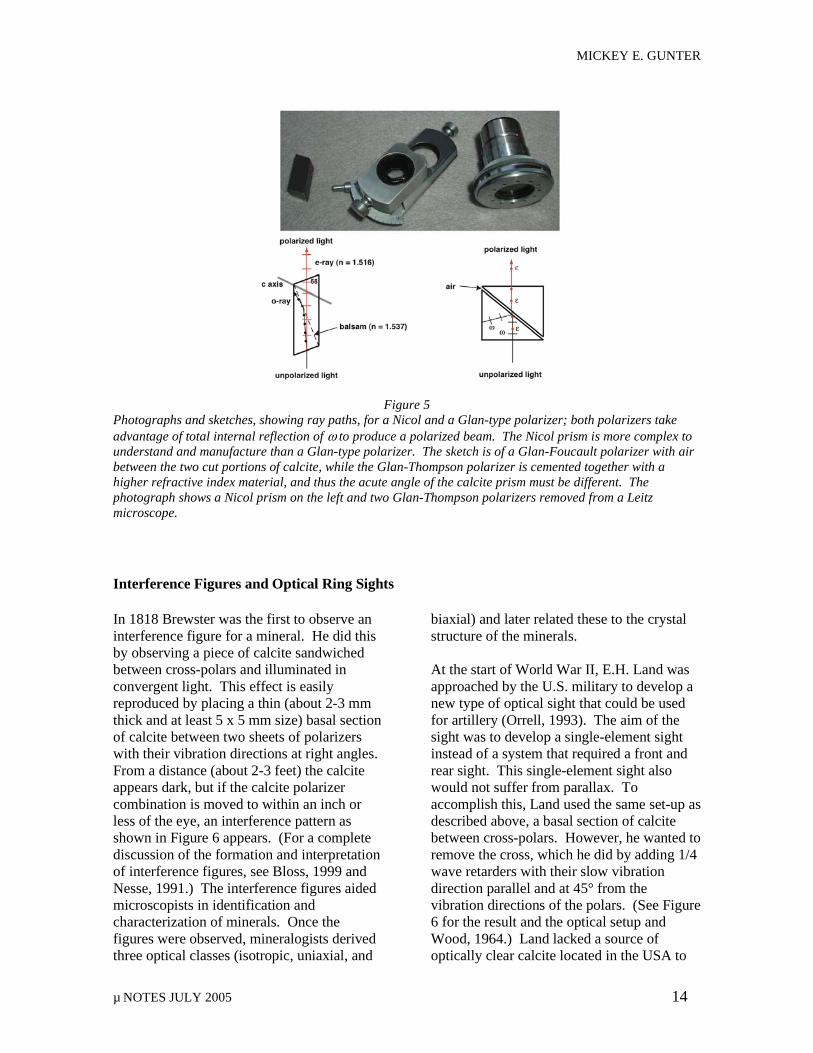
Calcite in Polarizers As noted in the above discussion of Snell’s law, when a ray moves from a material of high to low refractive index, it is refracted away from the normal. Because of this, there is some angle of incidence at which the angle of refraction would equal 90°. At this point, none of the ray is transmitted, and it is all reflected back into the medium of higher refractive index. Nicol took advantage of this fact and the that calcite yields two polarized waves of greatly different refractive index to produce the first polarizer prism, termed the Nicol prism, in 1829. To accomplish this, he cut a calcite rhomb in half and then glued the two pieces back together. Figure 5 shows a sketch of the light path through the prism. Upon entry, the unpolarized light is, as usual, broken into two mutually perpendicular polarized waves of different refractive index, ω = 1.658, an ε = 1.516. When the ω component strikes the balsam interface glue (n = 1.537), it undergoes total internal reflection and does not cross the balsam – calcite boundary; thus, the e-ray is left to travel through the second portion of the rhomb and emerge as a single polarized ray. By 1860, Nicol prisms were incorporated into
light microscopes to make the first true polarized light microscope to aid in the study of minerals and rocks (Kile, 2003).
The Nicol prism was replaced in the late 1800’s by the invention of the Glan-Thompson prism, which was easier to manufacture and had several other advantages. The Glan-Thompson prism (Figure 5) was also based on total internal reflection of the ω ray. In this case, the polarizer was made of pieces of calcite cut in such a way that the light traveled perpendicular to the optic axis, similar to the calcite prism face in Figure 4. The calcite was cut diagonally, and the ω ray is reflected at this boundary. In Figure 5, air is between the two pieces, but different types of glue can be used, which in turn would require the diagonal angles to differ. Development of sheet Polaroid in 1935 by E.H. Land (Kile, 2003) replaced the calcite-based polarizers in most applications. Even though the Nicol prisms have not been in wide use for nearly a century, microscopists often refer to “cross-Nicols” when viewing a sample in cross-polarized light.
MICKEY E. GUNTER
µ NOTES JULY 2005 14
Figure 5
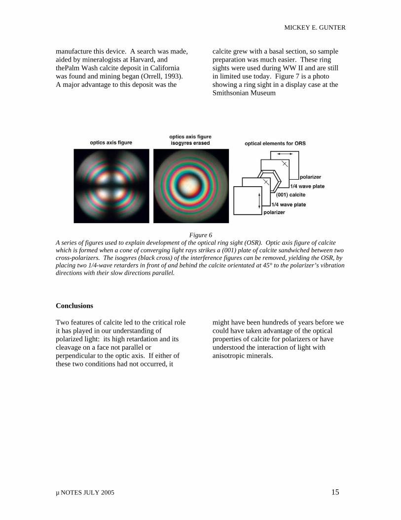
Photographs and sketches, showing ray paths, for a Nicol and a Glan-type polarizer; both polarizers take advantage of total internal reflection of ω to produce a polarized beam. The Nicol prism is more complex to understand and manufacture than a Glan-type polarizer. The sketch is of a Glan-Foucault polarizer with air between the two cut portions of calcite, while the Glan-Thompson polarizer is cemented together with a higher refractive index material, and thus the acute angle of the calcite prism must be different. The photograph shows a Nicol prism on the left and two Glan-Thompson polarizers removed from a Leitz microscope. Interference Figures and Optical Ring Sights In 1818 Brewster was the first to observe an interference figure for a mineral. He did this by observing a piece of calcite sandwiched between cross-polars and illuminated in convergent light. This effect is easily reproduced by placing a thin (about 2-3 mm thick and at least 5 x 5 mm size) basal section of calcite between two sheets of polarizers with their vibration directions at right angles. From a distance (about 2-3 feet) the calcite appears dark, but if the calcite polarizer combination is moved to within an inch or less of the eye, an interference pattern as shown in Figure 6 appears. (For a complete discussion of the formation and interpretation of interference figures, see Bloss, 1999 and Nesse, 1991.) The interference figures aided microscopists in identification and characterization of minerals. Once the figures were observed, mineralogists derived three optical classes (isotropic, uniaxial, and
biaxial) and later related these to the crystal structure of the minerals. At the start of World War II, E.H. Land was approached by the U.S. military to develop a new type of optical sight that could be used for artillery (Orrell, 1993). The aim of the sight was to develop a single-element sight instead of a system that required a front and rear sight. This single-element sight also would not suffer from parallax. To accomplish this, Land used the same set-up as described above, a basal section of calcite between cross-polars. However, he wanted to remove the cross, which he did by adding 1/4 wave retarders with their slow vibration direction parallel and at 45° from the vibration directions of the polars. (See Figure 6 for the result and the optical setup and Wood, 1964.) Land lacked a source of optically clear calcite located in the USA to
MICKEY E. GUNTER
µ NOTES JULY 2005 15
manufacture this device. A search was made, aided by mineralogists at Harvard, and thePalm Wash calcite deposit in California was found and mining began (Orrell, 1993). A major advantage to this deposit was the
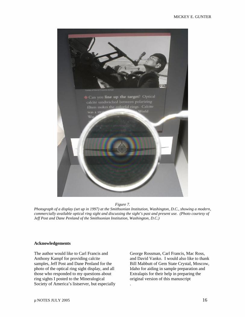
calcite grew with a basal section, so sample preparation was much easier. These ring sights were used during WW II and are still in limited use today. Figure 7 is a photo showing a ring sight in a display case at the Smithsonian Museum
Figure 6
A series of figures used to explain development of the optical ring sight (OSR). Optic axis figure of calcite which is formed when a cone of converging light rays strikes a (001) plate of calcite sandwiched between two cross-polarizers. The isogyres (black cross) of the interference figures can be removed, yielding the OSR, by placing two 1/4-wave retarders in front of and behind the calcite orientated at 45° to the polarizer’s vibration directions with their slow directions parallel. Conclusions Two features of calcite led to the critical role it has played in our understanding of polarized light: its high retardation and its cleavage on a face not parallel or perpendicular to the optic axis. If either of these two conditions had not occurred, it
might have been hundreds of years before we could have taken advantage of the optical properties of calcite for polarizers or have understood the interaction of light with anisotropic minerals.
MICKEY E. GUNTER
µ NOTES JULY 2005 16
Figure 7. Photograph of a display (set up in 1997) at the Smithsonian Institution, Washington, D.C., showing a modern, commercially available optical ring sight and discussing the sight’s past and present use. (Photo courtesy of Jeff Post and Dane Penland of the Smithsonian Institution, Washington, D.C.)
Acknowledgements The author would like to Carl Francis and Anthony Kampf for providing calcite samples, Jeff Post and Dane Penland for the photo of the optical ring sight display, and all those who responded to my questions about ring sights I posted to the Mineralogical Society of America’s listserver, but especially
George Rossman, Carl Francis, Mac Ross, and David Vanko. I would also like to thank Bill Mabbutt of Gem State Crystal, Moscow, Idaho for aiding in sample preparation and Extralapis for their help in preparing the original version of this manuscript .
MICKEY E. GUNTER
µ NOTES JULY 2005 17
Table I Time-table of significant events dealing with calcite and polarization, with associated direct and indirect references (modified from Kile, 2003): 1621: Willebrod Snellius develops Snell's law. A mathematical expression which relates angles of
refraction of a light ray to the refractive indices of the media (Kile, 2003). 1668: Earliest confirmed reports of the existence of “Iceland Spar” (i.e., optical grade calcite
cleavage rhombs) from the Helgustadir locality, Iceland (Kristjansson, 2002). 1669: Bartholinus (Bartholinus, 1669; Kristjansson, 2002) was the first to report on the
phenomenon he termed “double refraction” which he observed in “Iceland Spar.” 1808: Malus (Malus, 1808; Kile, 2003) was the first to discover, and name, polarization caused by
reflection of light while studying double refraction in calcite. 1811: Fresnel and Arago (Bloss, 1999) observed the two images formed by a calcite were
polarized. 1818: Brewster (Brewster, 1818; Kristjansson, 2002) discovered the formation of optic axis
interference figures when a calcite plate was illuminated with convergent light. 1829: Nicol (Nicol, 1829; Kile, 2003) invented the Nicol prism consisting of two differently
oriented pieces of calcite so as to produce a single beam of polarized light. 1860: First polarizing microscope to use Nicol prisms (Kile, 2003). 1881: S.P. Thompson invents the Glan-Thompson polarizer made of two pieces of calcite, but with
several advantages over the Nicol prism (Kile, 2003). 1935: E.H. Land invents the first sheet Polaroid (Kile, 2003) 1945: First commercially produced polarized light microscope to use sheet Polaroid References Bartholinus, E. (1669) Experimenta Crystalli
Islandici Disdiaclastici. Copenhagen, D. Paulli, 60 p.
Bloss, F.D. (1982) The Spindle Stage:
Principles and Practice. Cambridge University Press, Cambridge, England, 340 p.
Bloss, F.D. (1999) Optical Crystallography.
Mineralogical Society of America, Washington, D.C., 239 p.
Brewster, D. (1818) On the Laws of
Polarization and Double Refraction in Regularly Crystallized Bodies. Philosophical Transaction of the Royal Society, v. 108, 199-273.
Hecht, E. and Zajac, A. (1979) Optics.
Fourth Edition, Addison-Wesley Publishing Company, Reading, Massachusetts, 565 p.
Kile, D.E. (2003) The Petrographic Microscope: Evolution of a Mineralogical Research Instrument. Mineralogical Record, in press.
Kristjansson, L. (2002) Iceland spar: The
Helgustadir calcite locality and its influence on the development of science. The Journal of Geoscience Education, v. 50, n. 4, 419-427.
Malus E.L. (1808) Sur unepropriete de la
lumiere reflechie. Bulletin de Societe Philomathique, v. 1, 266-269.
Nesse, W.D. (1991) An Introduction to
Optical Mineralogy. Second Edition, Oxford University Press, New York, 335 p.
Nicol, W. (1829) On a Method of So Far
Increasing the Divergency of the Two Rays in Calcareous-Spar, That Only One

MICKEY E. GUNTER
µ NOTES JULY 2005 18
May Be Seen at a Time. Edinburgh New Philosophical Journal, v. 6, 83-84. Orrell, L. (1993) Mining California Calcite
Crystals for the Optical Ring Sight. California Geology, March/April, 45-49.
Wood, E.A. (1964) Crystals and Light. D.
Van Nostrand Company, Princeton, New Jersey, 160 p.
µ NOTES JULY 2005 19
Principles of Micromanipulators and Micromanipulation:
A Mid-Century SMSI Lecture-Demonstration-Workshop
John Gustav Delly
Consultant, McCrone Associates, Inc. Westmont, IL
Introduction
The early 1950’s were very active years for the State Microscopical Society of Illinois (SMSI). We know from newsletters and meeting announcements in the Society’s archives, that meetings, lectures, outings, and workshops were held at weekly intervals. One of these special programs was devoted to the design principles of micromanipulators, and the making of microtools for micromanipulation. In the mid 1960’s, when I was SMSI Curator, preparing a catalog of books in the Society’s library, I came across a single copy of the two handouts that were given to attendees at the Micromanipulator Workshop. One of these handouts was an eleven-page manuscript consisting of almost forty hand-sketched micromanipulator designs, together with the hand-written literature references they were taken from – and additional notes, in some cases. The other handout was a fifteen-page, mimeographed outline of the principles of micromanipulator design and micromanipulation tools and procedures. I
judged the contents of the handouts to be too valuable to remain inaccessible to the general membership, and so, in accordance with the Society’s State Charter, I determined to see that each member receive a copy. There was a problem, however; the originals consisted of spirit-duplicated mimeographs, which were difficult to read, and the backgrounds were heavily speckled. Thermal copy machines at the time, photographic efforts using various filter/film combinations, and even later copy machines were all unsuccessful in making clean reproductions. Recently, the eleven-pages of hand-sketched micromanipulator designs were scanned, and laboriously cleaned up using Adobe PhotoShop. Unfortunately, the 15-page outline was so fuzzy and difficult to read that the scanner could not recognize the original text; but Bonnie Betty of McCrone Associates volunteered to retype the text, preserving, as much as possible, the original font and format.
Micromanipulators and Micromanipulation “Micromanipulation” is the term used to include all operations performed in the microscopical field of vision, either free-hand, or with the aid of mechanical devices that guide the operating tools. For many operations, free-
hand is the way to go, if one has the necessary skill. But for other operations, such as procedures conducted on a single living cell – e.g., egg fertilization; nucleus removal or transfer, etc. – mechanically-assisted tool
JOHN GUSTAV DELLY
µ NOTES JULY 2005 20
movement is necessary. The first of these micromanipulators were the so-called “mechanical fingers;” usually relatively uncomplicated devices attached to the stage or objective, allowing the microscopist to mount or arrange diatoms, foraminifera, butterfly scales, etc. By 1859, H.D. Schmidt has described in the American Journal of Medical Science an accurate instrument for the dissection of tissue. Over the years, hundreds of designs have been proposed. Unfortunately, we do not know who conducted the SMSI workshop in 1953, and prepared the materials presented here, but the designs illustrated range from 1873 to 1950. Those who have access to back copies of The Microscope can find more information on mechanical fingers in 5 132 (1943), 11 230 (1957), and 13 87 (1961); and on micromanipulators in 9 305 (1954), 10 49, 80, 104 (1954), 10 137 (1955), 14 101 (1963), 14 216 (1964), 15 146 (1966), and 26 35 (1978). At one point in the outline here, the unknown author mentions “DeFonbrune,” without further reference. This refers to Pierre deFonbrune,
Chief of the Laboratories at the Pasteur Institute in Paris, who, in 1949, wrote the monograph, Technique de Micromanipulation. He was very influential in the design of micromanipulators and the manufacture and use of microinstruments. His monograph is highly illustrated. Another serious work on this subject is Micromanipulators and Micromanipulation by Hamed M. El-Badry; Academic Press, NY and Springer-Verlag, Vienna (1963). This book has 177 figures and an extensive bibliography. Interestingly, while proofing the draft of the new McCrone Microscopes and Accessories catalog, I noticed their offering of a micromanipulator, thus offering both free-hand and mechanically-assisted instruments for manipulating microscopic samples. We hope that readers will find these historic documents from their Society of interest – finally, after forty years. The original mimeographed copies are being returned to the SMSI archives to await some future technology.
JOHN GUSTAV DELLY
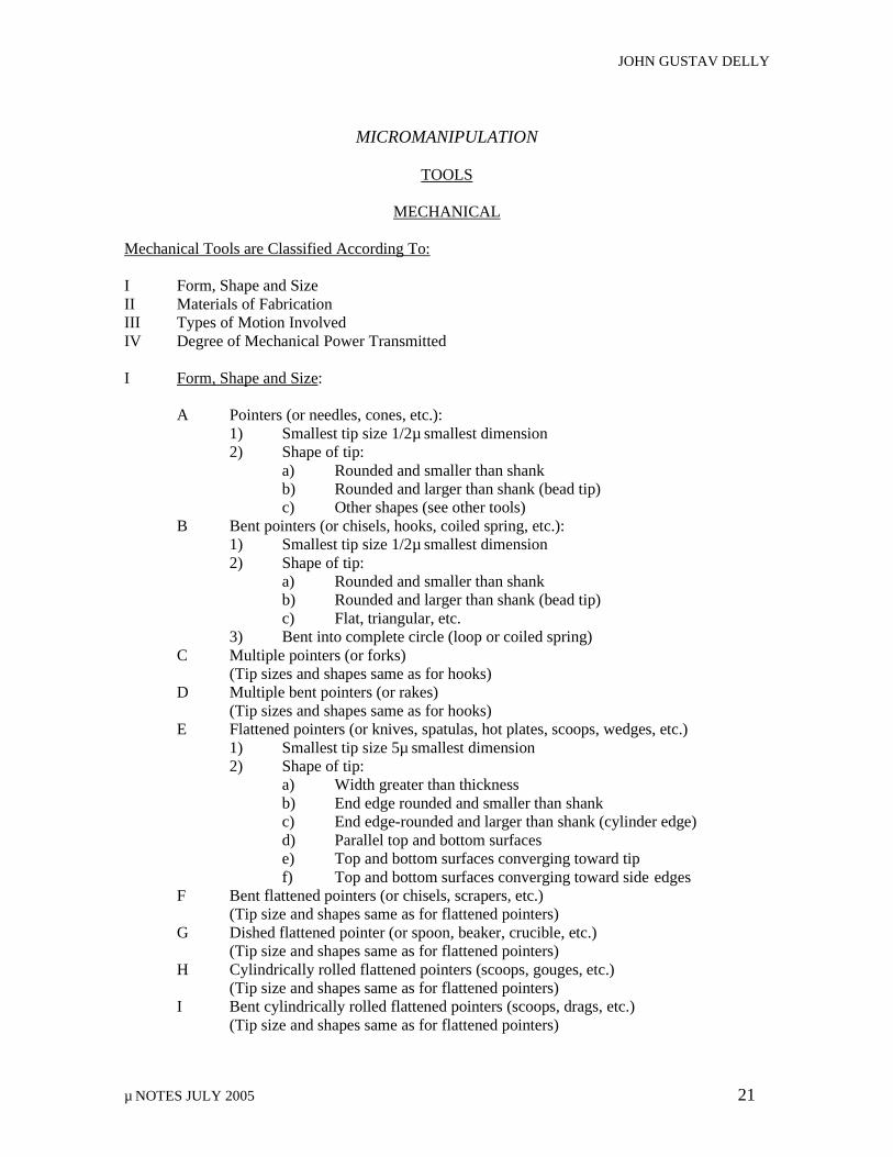
µ NOTES JULY 2005 21
MICROMANIPULATION
TOOLS
MECHANICAL
Mechanical Tools are Classified According To: I Form, Shape and Size II Materials of Fabrication III Types of Motion Involved IV Degree of Mechanical Power Transmitted I Form, Shape and Size: A Pointers (or needles, cones, etc.): 1) Smallest tip size 1/2µ smallest dimension 2) Shape of tip: a) Rounded and smaller than shank b) Rounded and larger than shank (bead tip) c) Other shapes (see other tools) B Bent pointers (or chisels, hooks, coiled spring, etc.): 1) Smallest tip size 1/2µ smallest dimension 2) Shape of tip: a) Rounded and smaller than shank b) Rounded and larger than shank (bead tip) c) Flat, triangular, etc. 3) Bent into complete circle (loop or coiled spring) C Multiple pointers (or forks) (Tip sizes and shapes same as for hooks) D Multiple bent pointers (or rakes) (Tip sizes and shapes same as for hooks) E Flattened pointers (or knives, spatulas, hot plates, scoops, wedges, etc.)
1) Smallest tip size 5µ smallest dimension 2) Shape of tip:
a) Width greater than thickness b) End edge rounded and smaller than shank c) End edge-rounded and larger than shank (cylinder edge) d) Parallel top and bottom surfaces e) Top and bottom surfaces converging toward tip f) Top and bottom surfaces converging toward side edges
F Bent flattened pointers (or chisels, scrapers, etc.) (Tip size and shapes same as for flattened pointers) G Dished flattened pointer (or spoon, beaker, crucible, etc.) (Tip size and shapes same as for flattened pointers) H Cylindrically rolled flattened pointers (scoops, gouges, etc.) (Tip size and shapes same as for flattened pointers) I Bent cylindrically rolled flattened pointers (scoops, drags, etc.) (Tip size and shapes same as for flattened pointers)
JOHN GUSTAV DELLY
µ NOTES JULY 2005 22
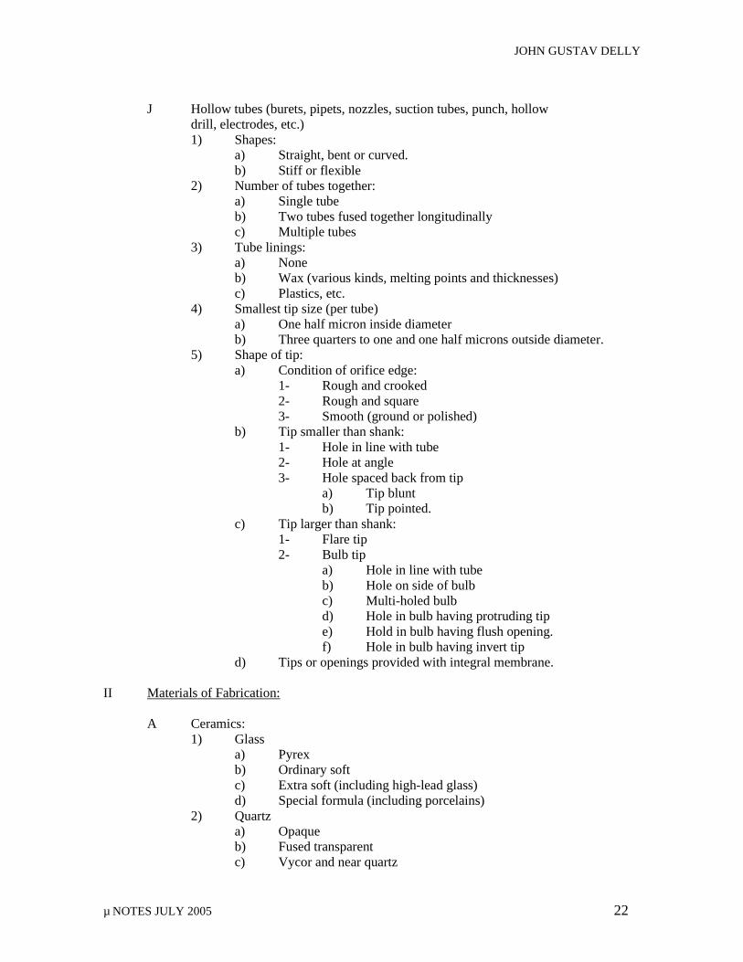
J Hollow tubes (burets, pipets, nozzles, suction tubes, punch, hollow
drill, electrodes, etc.) 1) Shapes:
a) Straight, bent or curved. b) Stiff or flexible
2) Number of tubes together: a) Single tube b) Two tubes fused together longitudinally c) Multiple tubes
3) Tube linings: a) None b) Wax (various kinds, melting points and thicknesses) c) Plastics, etc.
4) Smallest tip size (per tube) a) One half micron inside diameter b) Three quarters to one and one half microns outside diameter.
5) Shape of tip: a) Condition of orifice edge:
1- Rough and crooked 2- Rough and square 3- Smooth (ground or polished)
b) Tip smaller than shank: 1- Hole in line with tube 2- Hole at angle 3- Hole spaced back from tip
a) Tip blunt b) Tip pointed.
c) Tip larger than shank: 1- Flare tip 2- Bulb tip a) Hole in line with tube b) Hole on side of bulb c) Multi-holed bulb d) Hole in bulb having protruding tip e) Hold in bulb having flush opening. f) Hole in bulb having invert tip d) Tips or openings provided with integral membrane. II Materials of Fabrication: A Ceramics: 1) Glass a) Pyrex b) Ordinary soft c) Extra soft (including high-lead glass) d) Special formula (including porcelains) 2) Quartz a) Opaque b) Fused transparent c) Vycor and near quartz
JOHN GUSTAV DELLY
µ NOTES JULY 2005 23
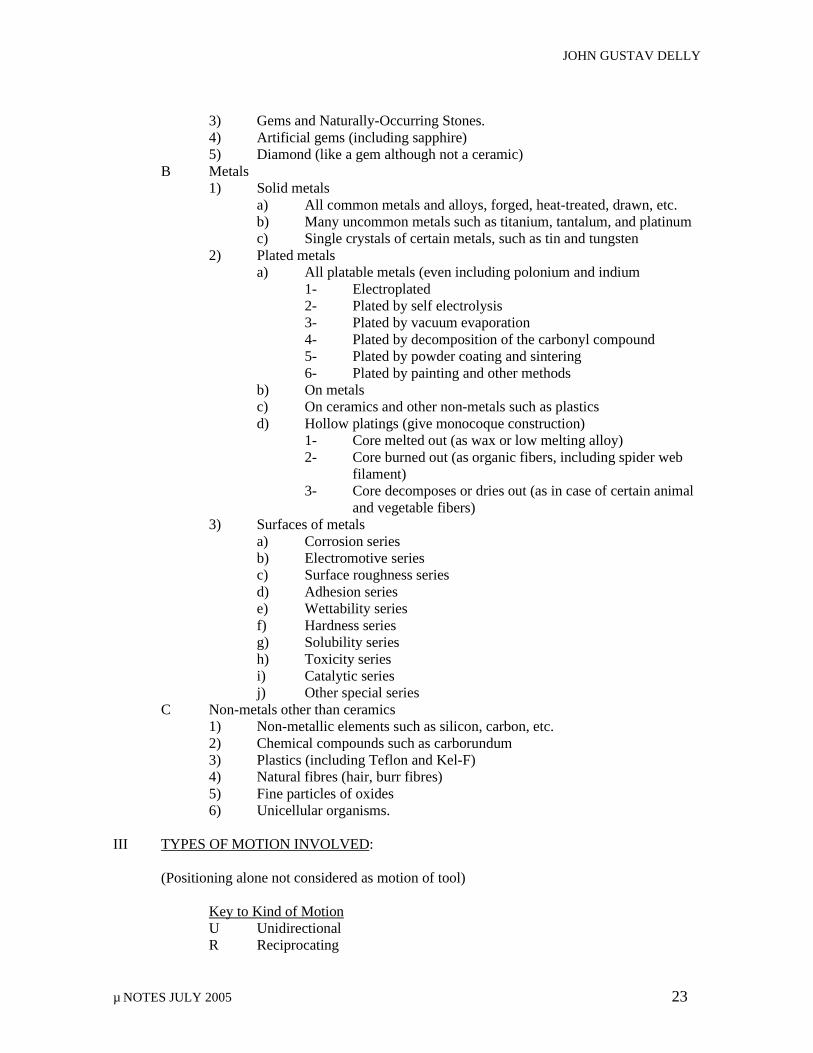
3) Gems and Naturally-Occurring Stones. 4) Artificial gems (including sapphire) 5) Diamond (like a gem although not a ceramic) B Metals 1) Solid metals a) All common metals and alloys, forged, heat-treated, drawn, etc. b) Many uncommon metals such as titanium, tantalum, and platinum c) Single crystals of certain metals, such as tin and tungsten 2) Plated metals a) All platable metals (even including polonium and indium
1- Electroplated 2- Plated by self electrolysis 3- Plated by vacuum evaporation 4- Plated by decomposition of the carbonyl compound 5- Plated by powder coating and sintering 6- Plated by painting and other methods
b) On metals c) On ceramics and other non-metals such as plastics d) Hollow platings (give monocoque construction)
1- Core melted out (as wax or low melting alloy) 2- Core burned out (as organic fibers, including spider web
filament) 3- Core decomposes or dries out (as in case of certain animal
and vegetable fibers) 3) Surfaces of metals
a) Corrosion series b) Electromotive series c) Surface roughness series d) Adhesion series e) Wettability series f) Hardness series g) Solubility series h) Toxicity series i) Catalytic series j) Other special series
C Non-metals other than ceramics 1) Non-metallic elements such as silicon, carbon, etc. 2) Chemical compounds such as carborundum 3) Plastics (including Teflon and Kel-F) 4) Natural fibres (hair, burr fibres) 5) Fine particles of oxides 6) Unicellular organisms. III TYPES OF MOTION INVOLVED: (Positioning alone not considered as motion of tool) Key to Kind of Motion U Unidirectional R Reciprocating
JOHN GUSTAV DELLY
µ NOTES JULY 2005 24
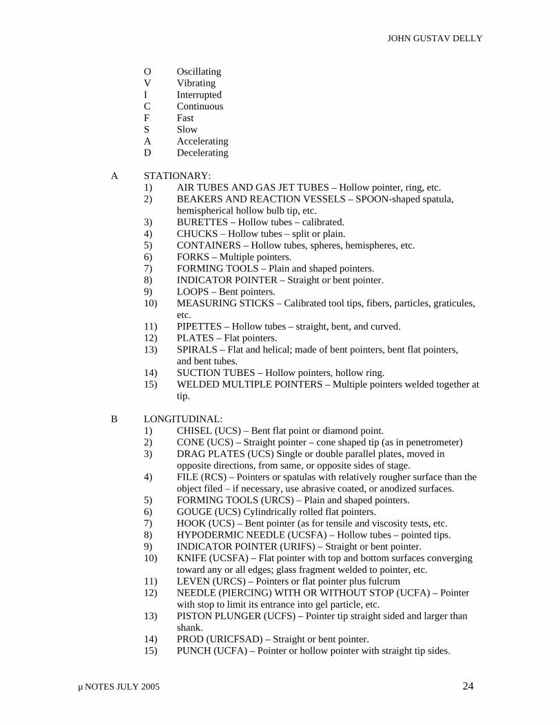
O Oscillating V Vibrating I Interrupted C Continuous F Fast S Slow A Accelerating D Decelerating A STATIONARY: 1) AIR TUBES AND GAS JET TUBES – Hollow pointer, ring, etc. 2) BEAKERS AND REACTION VESSELS – SPOON-shaped spatula,
hemispherical hollow bulb tip, etc. 3) BURETTES – Hollow tubes – calibrated. 4) CHUCKS – Hollow tubes – split or plain. 5) CONTAINERS – Hollow tubes, spheres, hemispheres, etc. 6) FORKS – Multiple pointers. 7) FORMING TOOLS – Plain and shaped pointers. 8) INDICATOR POINTER – Straight or bent pointer. 9) LOOPS – Bent pointers. 10) MEASURING STICKS – Calibrated tool tips, fibers, particles, graticules,
etc. 11) PIPETTES – Hollow tubes – straight, bent, and curved. 12) PLATES – Flat pointers. 13) SPIRALS – Flat and helical; made of bent pointers, bent flat pointers,
and bent tubes. 14) SUCTION TUBES – Hollow pointers, hollow ring. 15) WELDED MULTIPLE POINTERS – Multiple pointers welded together at
tip. B LONGITUDINAL: 1) CHISEL (UCS) – Bent flat point or diamond point. 2) CONE (UCS) – Straight pointer – cone shaped tip (as in penetrometer) 3) DRAG PLATES (UCS) Single or double parallel plates, moved in opposite directions, from same, or opposite sides of stage. 4) FILE (RCS) – Pointers or spatulas with relatively rougher surface than the
object filed – if necessary, use abrasive coated, or anodized surfaces. 5) FORMING TOOLS (URCS) – Plain and shaped pointers. 6) GOUGE (UCS) Cylindrically rolled flat pointers. 7) HOOK (UCS) – Bent pointer (as for tensile and viscosity tests, etc. 8) HYPODERMIC NEEDLE (UCSFA) – Hollow tubes – pointed tips. 9) INDICATOR POINTER (URIFS) – Straight or bent pointer. 10) KNIFE (UCSFA) – Flat pointer with top and bottom surfaces converging toward any or all edges; glass fragment welded to pointer, etc. 11) LEVEN (URCS) – Pointers or flat pointer plus fulcrum 12) NEEDLE (PIERCING) WITH OR WITHOUT STOP (UCFA) – Pointer with stop to limit its entrance into gel particle, etc. 13) PISTON PLUNGER (UCFS) – Pointer tip straight sided and larger than
shank. 14) PROD (URICFSAD) – Straight or bent pointer. 15) PUNCH (UCFA) – Pointer or hollow pointer with straight tip sides.
JOHN GUSTAV DELLY
µ NOTES JULY 2005 25
16) RAKE (RCS) – MULTIPLE BENT pointers. 17) RAM (UCFS) – Pointer. 18) SAW (RCS) – Rough edged knife or abrasive coated edge. 19) SCOOP (URCS) – Cylindrically rolled flat pointer. 20) SCRAPER (UIS) – bent, flat pointer. 21) SPATULA (UROCFSAD) – Flat pointer. 22) SPRING (UROCFSAD) – Coiled bent pointer or coiled fibers 23) TWEEZERS (UCS) Two almost parallel pointers advanced from same or
opposite sides of microscope stage. Tips spherical, cylindrical, flat, cupped, etc.
24) VISE OR CLAMP (UCS) – Two flat vertical surfaced pointer tips advanced from same or opposite sides of stage so that they press towards each other.
25) WEDGE (UCS) – Sloped flat pointer. C LATERAL: 1) FORMING TOOLS (URCS) – Plain and shaped pointers. 2) INDICATOR POINTER (URIFS) – Straight or flat pointers. 3) LEVER (URCS) – Pointer or flattened pointer plus fulcrum. 4) PENDULUM (ROFSAD) – Suspended weight. 5) PROD (URICFSAD) – Straight or bent pointer. 6) SHAKER (ROVFS) – Ring or clamp at end. 7) STIRRER (RVFS) – Pointer or bent or flattened bent pointer. 8) SPRING (URFSAD) – Pointer or flattened pointer. 9) TWEEZERS (UCS) – Two parallel pointers moved sideways toward each other, the pointers being controlled from the same or opposite sides of the microscope stage and the controlling points being at 90 degrees from the
direction of the pointers. 10) WEDGE (UCS) – Sloped flattened pointer. D VERTICAL: 1) AXE (RCFA) – Flat pointer with flat surfaces convergent. 2) FORMING TOOLS (URCS) – Plain and shaped pointers. 3) HAMMER (RCFA) – Bent pointer with flat or rounded tip. 4) INDENTER (UCS) – Cone or diamond point with point directed
downward. 5) INDICATOR POINTER (URIFS) – Straight or bent point. 6) LEVER (URCS) – Pointer or flattened pointer plus fulcrum. 7) PROD (URICFSDA) – Straight or bent pointer. E ROTARY: 1) DRILL (URCFSA) – Solid or hollow pointer with various shaped tips. 2) FORMING TOOLS (URCSFSA) – Flattened or shaped pointers or discs. 3) KNIFE (URCFS) – Disc welded at center to end of pointer tip. 4) GRINDER (URCFS) – Disc with thin or thick edge welded at center to
pointer tip. 5) ROLLER MILL (UCS) – Two pointers projected from opposite sides of
microscope stage with sides of tips rolling against each other in opposite directions.
JOHN GUSTAV DELLY
µ NOTES JULY 2005 26
6) SAW (URCS) – Disc welded at center to end of pointer tip and having
rough edge, or edge embedded with abrasive. 7) SCREW CONVEYOR (UCS) – Spiral surfaced pointer. 8) SPATULA (URICFSAD) – Flattened pointer. 9) TORSION SPRING (UROCFSAD) – Pointer or fiber, twisted axially.
F FLOATING TOOLS: (20 microns or less) 1) Spheres, cubes, platelets: fibers, rings or other shapes of magnetic material, controlled by magnetic fields and performing the functions of probes,
pointers, spatulas, rakes, hammers, projectiles, measuring standards, sides of magnetic clamps, sources of illumination and radioactivity, stirrers, lifters, floating supports, pullers, pushers, stoppers of Brownian movement (by adhesion), holders of chemicals by containing and by adhesion, introducers of chemicals, short circuiters of couplets, removers of undesired objects from field, etc.
2) The above floating tools are used for manipulation in pressure chambers, in special atmosphere chambers, and in hard-to-get-at positions. They are also used where control must be more delicate, or where the tool must be moveable and turnable to a wide variety of positions quickly. A special use is to test the elasticity and membrance strength of gels by insertion of one or more magnetic particles into the gel followed by magnetic micromanipulation.
3) Magnets are not needed for remote control of certain particles that can be moved by static effects.
4) Torn plastic films and films in the act of tearing under the influence of the electron beam in the electron microscope act as manipulating tools for handling submicroscopic particles in the electron microscope.
5) Floating tools in liquids include the Cartesian diver operated by pressure. They also include floating tools moved by or in liquids by colloidal and hydraulic effects.
6) Sticky plastic films when stretched and contracted act as remote control manipulators for particles and floating tools adhered thereto.
IV DEGREE OF MECHANICAL POWER TRANSMITTED: A ZERO POWER: 1) AIR AND GAS JET TUBES – Hollow pointer, ring, etc. 2) BEAKERS AND REACTION VESSELS – Spoon shaped spatula, hemispherical hollow bulb tip. 3) BURETTES – Hollow tubes – calibrated. 4) CONTAINERS – Hollow tubes, spheres, hemispheres. 5) INDICATOR POINTER 6) MEASURING STICKS – Calibrated tool tips, fibers, particles, graticules,
etc. 7) PIPETTES – Hollow tubes – straight, bent, and curved. 8) SUCTION TUBES – Hollow pointers, hollow rings 9) WELDED MULTIPLE POINTERS – Multiple pointers welded together at
tip.
JOHN GUSTAV DELLY
µ NOTES JULY 2005 27
B LIGHT POWER: 1) CHUCKS – Hollow tubes – split or plain. 2) DRAG PLATES – Single or double parallel plates moved in opposite
directions, for same or opposite sides of stage. 3) HYPODERMIC NEEDLE – Hollow tubes pointed.
4) KNIFE – Flat pointer with top and bottom surfaces converging toward any or all edges; glass fragment welded to pointer.
5) INDICATOR POINTER – Straight or bent pointer. 6) LOOP – Bent pointer.
7) NEEDLE – PIERCING – WITH OR WITHOUT STOP – Pointer with or without stop to limit its entrance into gel particle, etc.
8) PENDULUM – Suspended weight. 9) PLATES – Flat pointers. 10) PROD – Straight or bent pointers. 11) RAKE – Multiple bent pointers. 12) SHAKER – Ring or clamp at end of pointer.
C MEDIUM POWER 1) CONE – Straight pointers – cone shaped tip (penetrometer, etc.) 2) DRILL – Solid or hollow pointers with various shaped tips. 3) FILE – Pointers or spatulas – relatively rougher surfaced than object filed –
anodized AL – abrasive coated surface. 4) FORKS – Multiple pointers. 5) FORMING TOOLS – Plain and shaped pointers. 6) GRINDER – Disc with thin or thick edge welded at center to pointer tip. 7) LEVER – Pointers or flat pointers plus fulcrum. 8) LOOP – Bent pointers. 9) PISTON PLUNGER – Pointer tip straight sided and larger than shank. 10) SAW – Rough edged knife – or abrasive coated edge. 11) SCOOP – Cylindrically rolled flattened pointers. 12) SCRAPER – Bent flat pointers. 13) SPATULA – Flat pointers. 14) TWEEZERS – Two almost parallel pointers with variously shaped tips
advanced from same or opposite sides of stage. 15) WEDGE – Sloped flat pointers.
D HEAVY POWER: 1) AXE – Flat pointers – flat surfaces convergent. 2) CHISEL – Bent flat pointers or diamond points. 3) GOUGE – Cylindrically rolled flat pointers. 4) HAMMER – Bent pointers with flat or rounded tips. 5) HOOK – Bent cylindrical or flat pointers. 6) INDENTER – Cone or diamond point directed at right angles to the tool
shank. 7) PUNCH – Pointers, solid or hollow, with straight tip sides. 8) RAM – Pointers. 9) ROLLER MILL – Two pointers projected from opposite sides of stage
with sides of tips rotating against each other in opposite direction. 10) SCRAPER – Bent flat pointers.

JOHN GUSTAV DELLY
µ NOTES JULY 2005 28
11) SPRING – Coiled bent pointers or coiled fibers (as wool, etc.) 12) TORSION SPRING – Pointer or fiber twisted axially. 13) VISE OR CLAMP – Two flat vertical surfaced pointer tips advanced from
same or opposite sides of stage so that they press toward each other.
ELECTRICAL
Electrical Tools are Classified According To: I Electrical Only II Electro Chemical III Electro Colloidal IV Electro Mechanical V Electro Temporal VI Electro Thermal I Electrical Only: A Arc electrodes B Capacity cell C Electrometer D Electrostatic cell E Electrostatic pointers F Galvanometer G Induction Coil H Magnets and electrets I Resistance prods J Spark electrodes II Electro Chemical: A Conductivity cell B Electrolysis cell C Electro pipet D pH electrode III Electro Colloidal: A Centrifuge B Electro dialysis cell C Electrophoresis cell IV Electro Mechanical: A Electro drill B Magnetic hook C Magnetic prod D Magnetic ring E Magnetic stirrer or shaker F Piezo-electric crystal G Rotating arbor
JOHN GUSTAV DELLY
µ NOTES JULY 2005 29
V Electro Temporal: A Signal generator B Timer signal VI Electro Thermal: A Arc heater B Electrolytic heater C High frequency heater D Induction heater E Resistance heater F Spark heater G Thermistor H Thermo couple Thermal Tools Are Classified According To: I Thermal Only II Thermal Colloidal III Thermal Electrical IV Thermal Mechanical V Thermal Optical VI Thermal Physical-Chemical I Thermal Only: A Blast Burner B Calorimeter C Fusion furnace D High frequency forming and heat treating coil E Hot oil bath F Hot plate G Hot spatula H Hot wire I Induction forming and heat treating coil J Soldering “iron” K Thermos or Dewar container II Thermal Colloidal: Schlieren cell III Thermal Electrical: A Thermistor B Thermocouple C Thermopile IV Thermal Mechanical: A Autoclave cell B Expansion chuck
JOHN GUSTAV DELLY
µ NOTES JULY 2005 30
C Expansion piston D Expansion ram E Expansion ring F Hot and cold pointers G Hot and cold tweezers V Thermal Optical: A Infra-red lamp B Schlieren cell VI Thermal Physical-Chemical: A Boiling point cell B Crystals as temperature and humidity indicators C Distillation capillaries and cells D Evaporation cell E Freezing point cell F Melting point cell G Metal dipping cell H Metal evaporating cell I Molecular still J Sublimation cell
ATMOSPHERIC ATMOSPHERIC TOOLS ARE CLASSIFIED AS FOLLOWS: I Active (as distinguished from inert) Atmosphere Cell II Atomization (Fog) Cell III Dust-free and/or Germ-free Cell IV Humidity Cell V Inert Atmosphere Cell VI Ionized Atmosphere Cell
OPTICAL OPTICAL TOOLS (in addition to conventional equipment) ARE CLASSIFIED AS FOLLOWS: I Fluorescent or radioactive particle as a localized source of light or as a source of other
radiation II Quartz or plastic tube, ring or pointer as a directed light source (straight or bent)
COLLOIDAL
COLLOIDAL TOOLS ARE CLASSIFIED AS FOLLOWS: I Adsorption Pipet II Atomizer III Capillaries IV Centrifuge and Spinning Drop V Dialysis Cell VI Diffusion Cell or Capillary
JOHN GUSTAV DELLY
µ NOTES JULY 2005 31
VII Electro-dialysis Cell VIII Electrophoresis Cell IX Extraction Cell X Film Trough XI Filter XII Granular or Graticular surface with colloidal sized spaces XIII Homogenizer Pipet XIV Micro Muller XV Schlieren Cell XVI Sedimentation Cell XVII Surface Tension as a Tool XVIII Viscosity Hook or Plates
BIOLOGICAL
BIOLOGICAL TOOLS ARE MICROORGANISMS USED AS TOOLS IN THE FOLLOWING WAYS: I Direct Mechanical Action of the Microorganism II Enzymolysis, Oxidation, etc. III pH Measurement
FABRICATION
METHODS
MECHANICAL TOOLS FABRICATION: I POINTERS (AND VARIATION): A Glass, Pyrex, etc.: 1) Draw glass rod out to small diameter: a) By hand using tweezers, and accelerating the pull by flip of the
wrist and fingers, or, b) By automatic machine puller, or, c) By de Fonbrun’s method, under the microforge, i.e., by hanging
weights on a hooked end of glass tubing while heating the glass at a point above the hook, using radiant heat from an electrically resistance-heated hot wire.
d) By microforge in general: 1- Heat supplied by a- Resistance wire radiant heat, b- High frequency coil, c- Flame. 2- Pull supplied by: a- Hanging weights, b- Direct downward pull of a manipulator having a
long rapid vertical stroke, c- Direct horizontal pull of a manipulator having a
long rapid horizontal stroke. 2) Bend, shape, and form the pointers into flats, curves, rings, spirals, etc., by
JOHN GUSTAV DELLY
µ NOTES JULY 2005 32
3) use of micro forge, heated as above, and aided by forming tools and
manipulator controls. 4) Plate the glass tools (either before or after forming – or both) by vacuum
evaporation, electroplating, etc.: a) Rotating while plating if entire surface is to be coated, b) Stopping-off undesired areas to give selective forming by plating, c) Using successive layers of metal or metals and non-metals as
required d) To give strength or a better surface (see series of surfaces under
materials). 5) In some cases, fabricate the tips separately:
a) Scratch surface of glass or gem stone, etc. with diamond point and select chips of desireable shapes (as with sharp edges for ultra micro knives)
b) Make metal or plastic tips, c) Attach these separate tips onto shank of tool by:
1- Welding, 2- Gluing, 3- Use of shrink-fit chuck.
d) Make circular glass flake knife by touching tip of hot pointer to surface of cooler hollow sphere or bulb. A tiny flake of glass is cracked off the outer surface of the bulb and this tiny flake is simultaneously welded at its center to the tip of the pointer. The edge of the flake thus formed can be less than .4 micron.
5) Where multiple pointers are used as in case of forks, rakes, etc., the tips are mounted as follows:
a) As integral part of shank (large rod or tube drawn down, b) In several parallel glass tubes: 1- Fused or glued together longitudinally: a- Inside large glass tube, b- No outer tube, 2- Straight or bent, etc. c) In converging glass tubes, d) In diverging glass tubes. B Metal 1) Over 5 microns smallest dimension: a) Cut steel drill rod (size #40) to about 6” long. b) Rough grind point to 40 microns tip diameter on rubber bonded
grindwheel. 1- Wet fingers to allow free rotation or rod. 2- Grind to slow tapered point; tapered to one or two inches back from tip. 3- Dip in water to cool whenever tip gets too soft. 4- When dipping in water no longer hardens tip sufficiently,
then 5- Harden tip by applying match flame about ½ inch back
from tip until red, and then plunging into water or oil to quench.
c) Fine grind below 40 microns down to 20 microns on metallurgical
JOHN GUSTAV DELLY
µ NOTES JULY 2005 33
cloth lapping wheel or equivalent with aluminum oxide powder or other appropriate abrasive, and water. 1- Revolve pointer against cloth lapping wheel, with wheel rotating in same direction as pointer, and with pointer
parallel to rim of wheel. 2- Measure size of pointer frequently under low power
microscope. 3- Re-harden as often as necessary. 4- When pointer gets so fine that revolving is difficult without
damaging pointer (because of uneven surface of wheel), 5- Hold pointer against wheel without revolving pointer, or, 6- Change to a more even or smaller lapping wheel, or, 7- Proceed to a more refined method of reducing size of
pointer still further d) If pitting prevents getting point down to 5 microns then try another
piece of drill rod or try heat treatment to strengthen the structure. 2) Below 5 microns smallest dimension: a) Start with 5 micron diameter tip. b) Dip in molten salt bath, or c) Electrolyze metal away by reverse electrolysis or by Bullard-Dunn
process (plate tin onto pointer and remove by reverse electrolysis). d) Hot forge the tip with the micro forge, using induction or resistance heating if necessary. e) Plate pointer if necessary: 1- By vacuum evaporating a film of metal onto the pointer, or 2- By electroplating a film of metal onto the pointer, or 3- By fusing a coating of ceramic or thermosetting resin
material onto the pointer and removing the ceramic or resin coating at the tip and back from the tip as far as possible (still retaining desired strength at tip), or,
4- By shrink fitting a metal tube over the pointer, down to within a small distance of the tip.
5- For reinforcement of pointer or for better surface (see series of surfaces under materials).
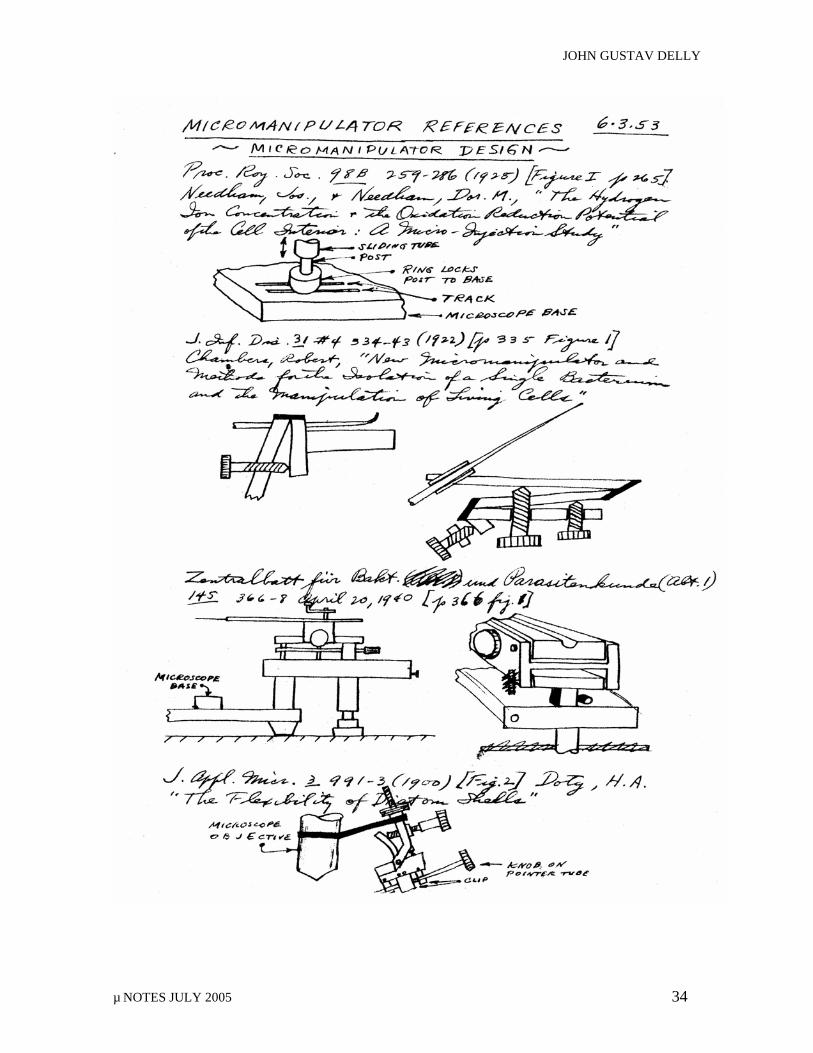
JOHN GUSTAV DELLY
µ NOTES JULY 2005 34
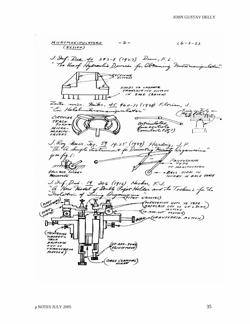
JOHN GUSTAV DELLY
µ NOTES JULY 2005 35
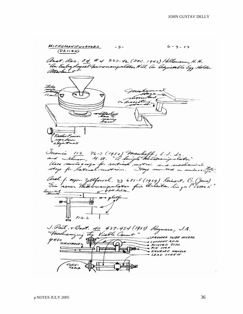
JOHN GUSTAV DELLY
µ NOTES JULY 2005 36
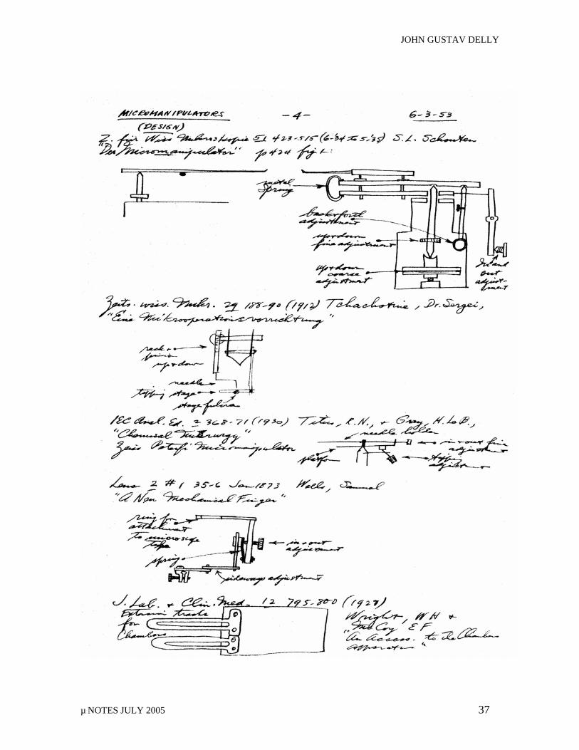
JOHN GUSTAV DELLY
µ NOTES JULY 2005 37
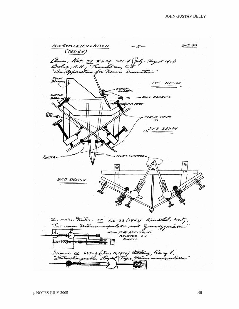
JOHN GUSTAV DELLY
µ NOTES JULY 2005 38
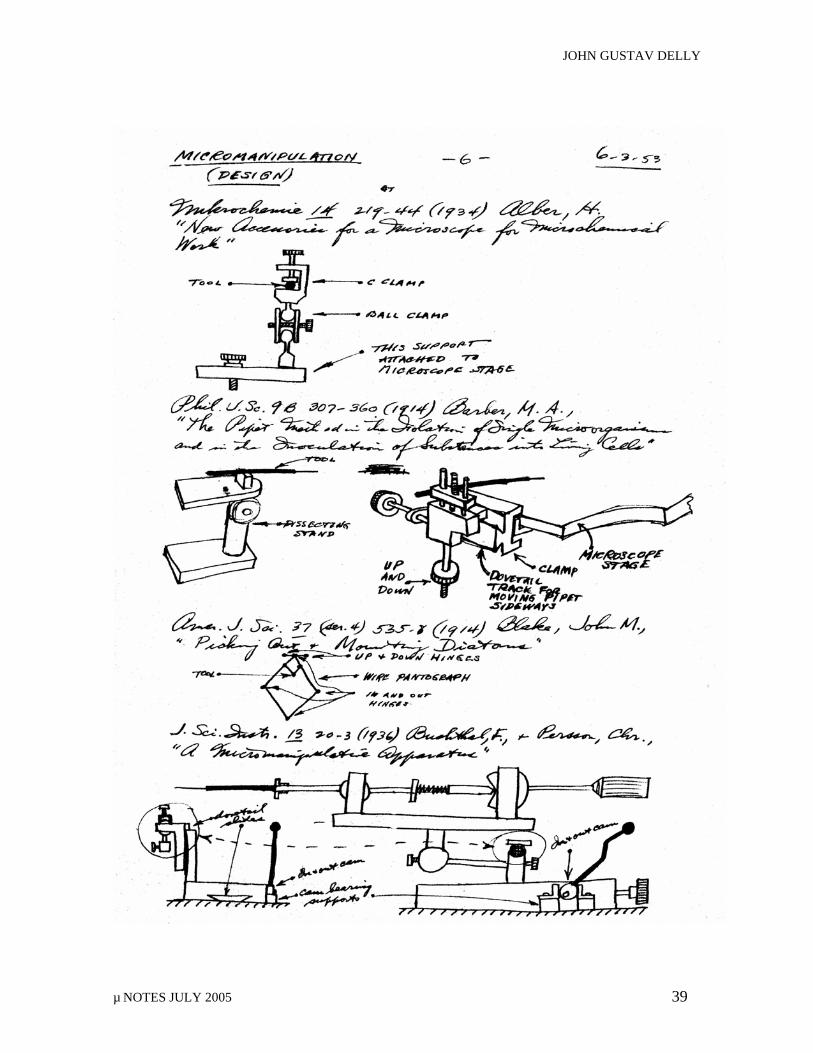
JOHN GUSTAV DELLY
µ NOTES JULY 2005 39
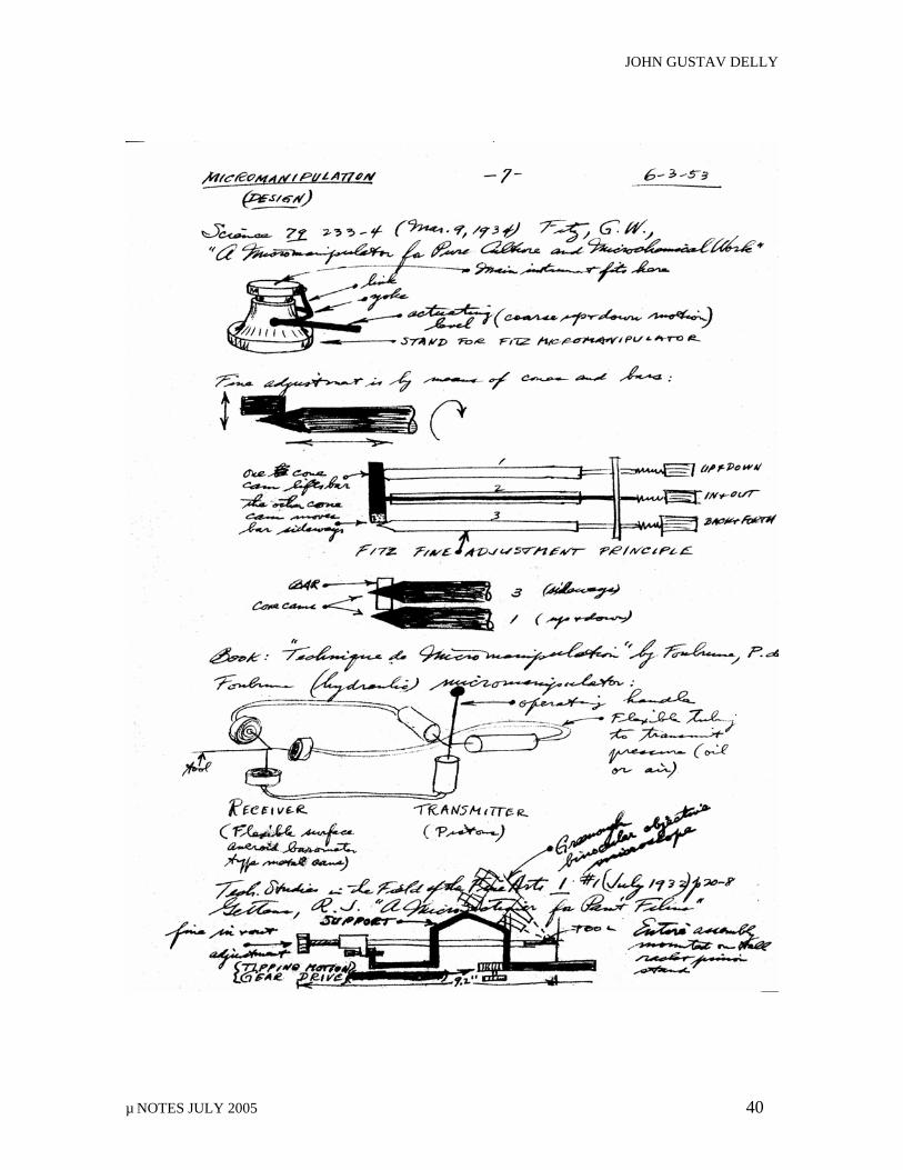
JOHN GUSTAV DELLY
µ NOTES JULY 2005 40
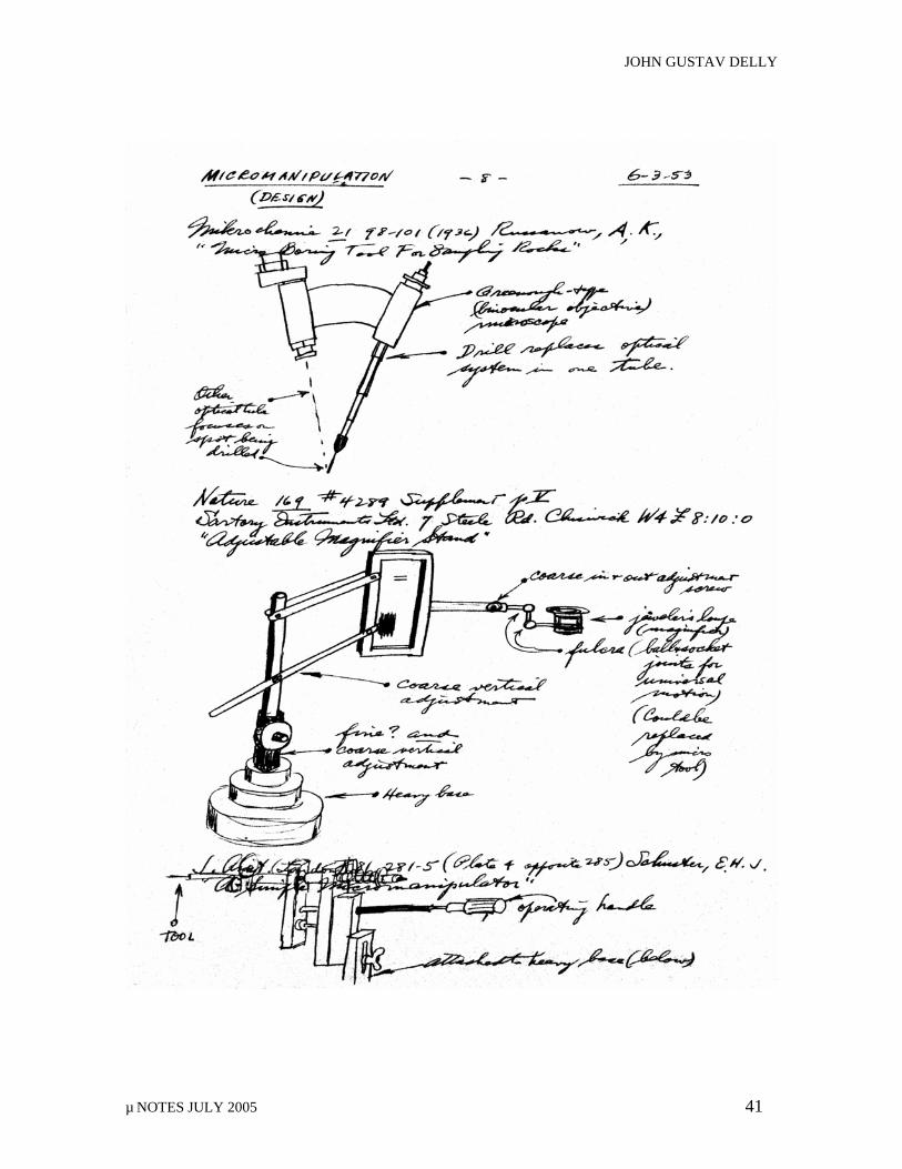
JOHN GUSTAV DELLY
µ NOTES JULY 2005 41
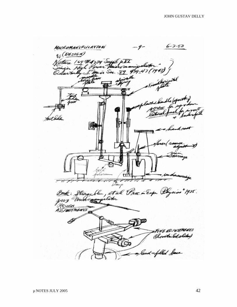
JOHN GUSTAV DELLY
µ NOTES JULY 2005 42
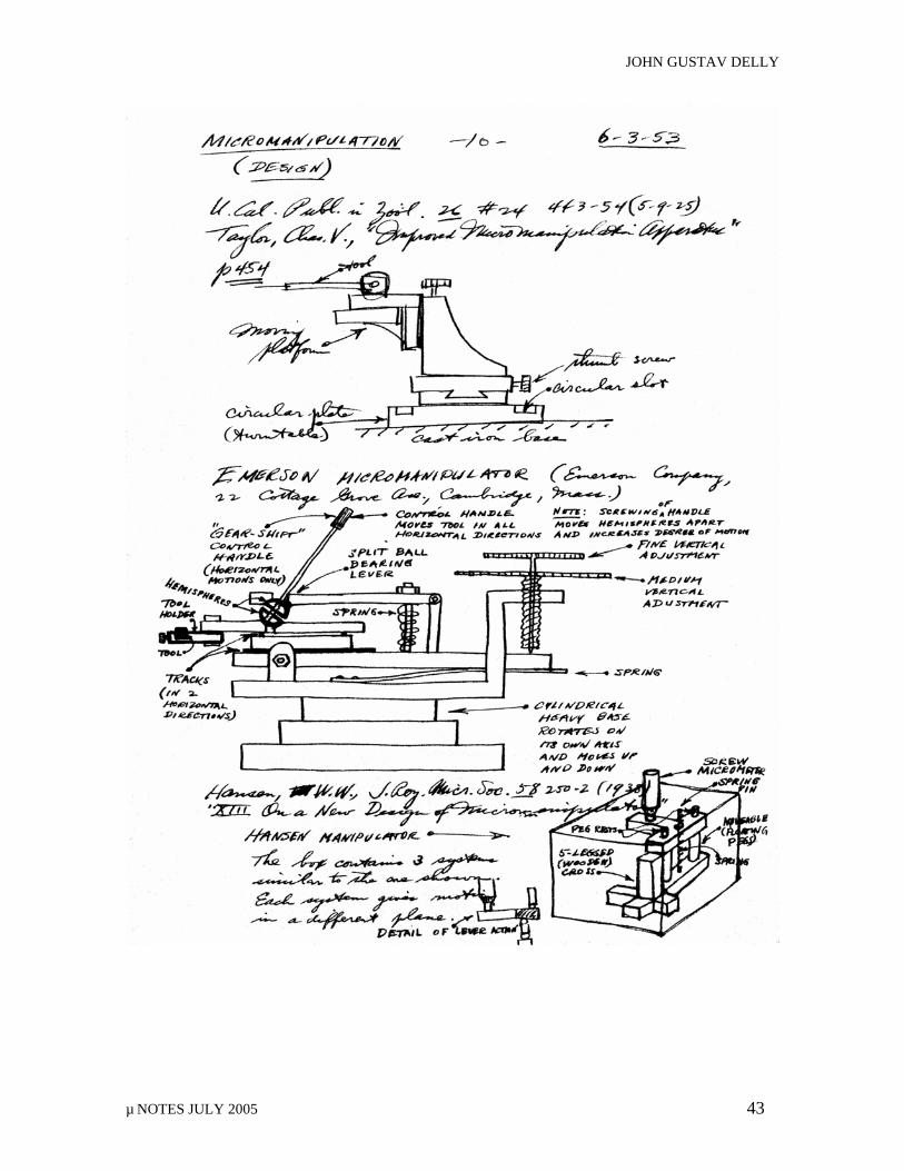
JOHN GUSTAV DELLY
µ NOTES JULY 2005 43
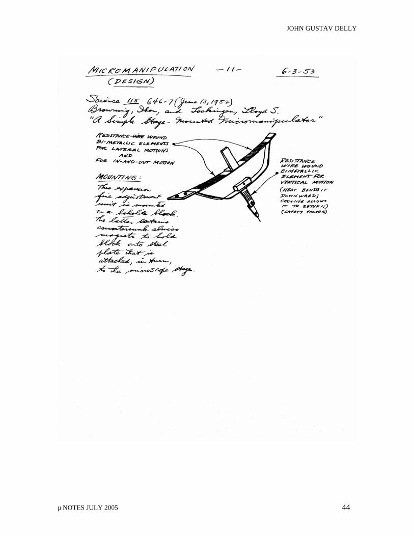
JOHN GUSTAV DELLY
µ NOTES JULY 2005 44
BILL C. MIKUSKA
µ NOTES JULY 2005 45
SMSI President’s Report: July 2004 – July 2005
Since July of 2004, SMSI has been engaged with educational projects, some that were on-going, some that are new, and some yet to be. In the fall of 2004, SMSI taught a six Saturday morning course in Polarized Light Microscopy to grade 7-12 teachers at the Argonne National Laboratory. Even a second year post-doctoral student at Argonne enrolled in this course; his evaluation of the course was a check for a membership to SMSI. A $30.00 fee covered the cost of optical materials and photocopying , but, unlike past courses offered by SMSI, participants could elect to receive one graduate hour of college credit through Aurora University; this allows teachers to move up on their school’s salary schedule. Although CEU’s and CPDU’s were accumulative for similar purposes, the State of Illinois decided that the associated bookkeeping morass associated with these was problematic. The final exam for SMSI’s course was an oral presentation and accompanying written term paper demonstrating how the course content would be applied in the classroom. Another course that is designed for biology teachers and others is currently on the chalkboard. SMSI is in contact with the IABT, Illinois Association of Biology Teachers, and plans to teach a flexible, non-continuous course to teachers for two (2) graduate hours through Aurora University at IMSA, the Illinois Math and Science Academy – the brainchild of Nobel Prize Laureate in Physics, Leon Lederman.
Lederman, former Director of Fermi National Accelerator Laboratory in Batavia, Illinois, and of top quark fame, is very much educationally minded. It is in the Leon Lederman Educational Center that SMSI has taught Introduction to Polarized Light Microscopy for the past three springs; we are invited back for a fourth season. The ambitious course outlines, although they may appear the same, are adjusted to student needs and understanding, and may be found online at www.smsi.org not at “Lake Woebegone.” The rough topical outline for the IABT course to be follows: 1. The light microscope, its parts, Koehler illumination, and what microscope manufacturers fail to tell the consumer 2. Sample preparations, selecting the proper cover glass thickness for your microscope objectives, slide cleaning, and glass vs. plastic slides and cover slips 3. Ducks, butterflies, transverse waves, diffraction, optical aberrations, and polarization. 4. Which end of the microscope do you look through ---photomicrography vs. microphotography 5. Diatoms, objectives. numerical aperture and resolution, maximum usable magnification, and microtomy
BILL C. MIKUSKA
µ NOTES JULY 2005 46
6. Diatoms, snowflakes, and butterfly scales as art forms 7. Refractive index, birefringence, hair, natural fibers and the Herzog twist 8. Oil immersion objectives---How many drops of immersion oil are necessary and where are they placed for optimum sample resolution. 9. Scarab beetles, circular polarized light, optical activity (circular birefringence), sugars and drugs 10. Optical sectioning and software 11. Gall and kidney stones and polarized light 12. Dispersion staining---The haystack, the needle, and cocaine 13. Rheinberg illumination (staining with light), chemical staining and the amplitude vs. phase domains---basic phase contrast 14. Seaweeds and calcite 15. Sumac berry hairs and acid base indicators 16. Pollens: Both recently gathered pollens and those "fossilized" (the term referring to recent pollens chemically treated for micro mounts). Pollens have been suggested to the DEA and other agencies for drug smuggling from foreign countries. 17. Limits of the light microscope, the scanning electron microscope, and the future of light microscopy: a new beginning
SMSI is also pursuing monies for student polarized light microscopes. The scopes we now use are those at Argonne and at Fermilab, and in the future, at IMSA. Although not pol-scopes, they serve well for teaching participants to learn how to modify extant classroom scopes, especially where teachers have very limited budgets. Various SMSI members involved with teaching these courses bring their own pol-scopes for demonstrating modifications to classroom scopes and time-saving sample viewing. Emphasis in these courses is placed on concepts of basic optics and polarized light in nature, from rainbows, to crystals, to Fermilab’s scintallating detector fibers: all demonstrated macroscopically. Microscopical ramification is the icing on the cake. Depending upon time and course location, students tour various facilities ranging from a Scanning Confocal Electron Microscope, SCEM, with a lecture by its inventor, to a neutrino detector by the person who steers one of the world’s highest energy particle beams. Lastly, SMSI has been actively pursuing updating our web site by trying to get our history available to those of us in the present and by making corrections such that all visitors, regardless of computer platform, extended ASCII vs. normal ASCII characters, and the ongoing bickering between two major font purveyors. The tables below reflect our site’s activity over the past year. My regret for this past year is that more had not been accomplished and that I am not still in school.
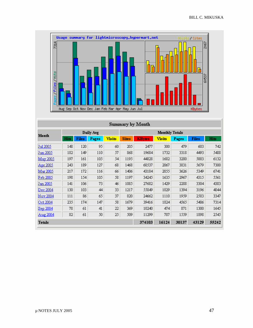
BILL C. MIKUSKA
µ NOTES JULY 2005 47
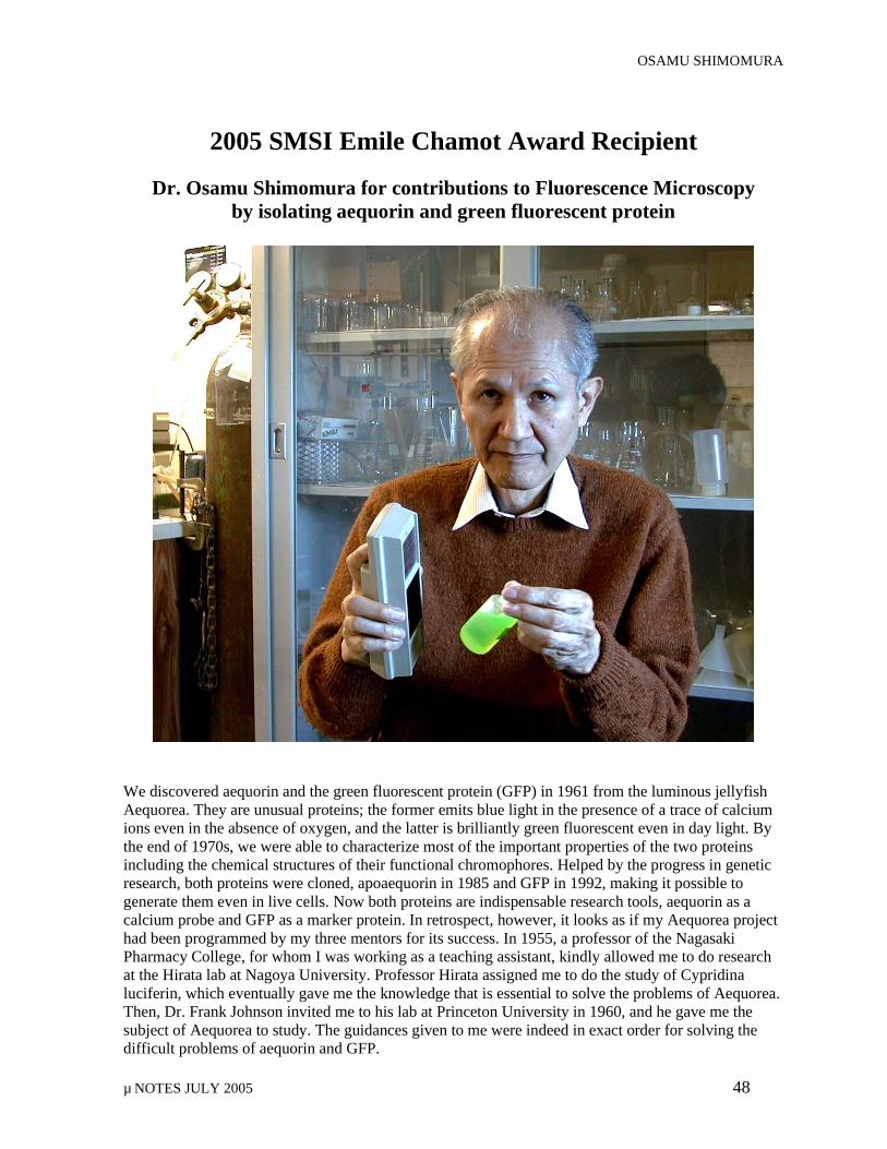
OSAMU SHIMOMURA
µ NOTES JULY 2005 48
2005 SMSI Emile Chamot Award Recipient
Dr. Osamu Shimomura for contributions to Fluorescence Microscopy by isolating aequorin and green fluorescent protein
We discovered aequorin and the green fluorescent protein (GFP) in 1961 from the luminous jellyfish Aequorea. They are unusual proteins; the former emits blue light in the presence of a trace of calcium ions even in the absence of oxygen, and the latter is brilliantly green fluorescent even in day light. By the end of 1970s, we were able to characterize most of the important properties of the two proteins including the chemical structures of their functional chromophores. Helped by the progress in genetic research, both proteins were cloned, apoaequorin in 1985 and GFP in 1992, making it possible to generate them even in live cells. Now both proteins are indispensable research tools, aequorin as a calcium probe and GFP as a marker protein. In retrospect, however, it looks as if my Aequorea project had been programmed by my three mentors for its success. In 1955, a professor of the Nagasaki Pharmacy College, for whom I was working as a teaching assistant, kindly allowed me to do research at the Hirata lab at Nagoya University. Professor Hirata assigned me to do the study of Cypridina luciferin, which eventually gave me the knowledge that is essential to solve the problems of Aequorea. Then, Dr. Frank Johnson invited me to his lab at Princeton University in 1960, and he gave me the subject of Aequorea to study. The guidances given to me were indeed in exact order for solving the difficult problems of aequorin and GFP.