Embed Size (px)
Citation preview

ISSN (Print) : 2320 – 3765 ISSN (Online): 2278 – 8875
International Journal of Advanced Research in Electrical,
Electronics and Instrumentation Engineering (An ISO 3297: 2007 Certified Organization)
Vol. 5, Issue 3, March 2016
Copyright to IJAREEIE DOI:10.15662/IJAREEIE.2016.0503007 1242
A Modelling of 440 KV EHV Transmission Line Faults identified and Analysis by Using
MATLAB Simulation Satish Karekar1, Tripti Barik2
B.E. Student, Dept. of EE, Parthivi College of Engineering and Management, Sirsakala Bhilai-3, Chhattisgarh, India1
M. Tech Student [VLSI & ES], Dept. of ETC, Institute of Technical Education and Research, Bhubaneswar, India2
ABSTRACT: As we know electricity or electrical power are increases day by day and transmits more electrical power by increasing the transmission line capacity from one sub-station to another sub-station. During some faults are occurred in the long transmission line system, such as single line to ground fault (L-G), double line to ground (2L-G), triple line to ground fault (3LG) and Line to line fault (L-L). These types faults are affecting the electrical power system equipment’s/component which are connect in EHV Transmission line. Mainly the major faults in long transmission lines is (L-G) single line to ground fault which are harmful to the electrical equipment. A proposed model in 300km/440kv EHV transmission line are simulated in MATLAB software to analysis and identified the faults.Fault block was taken from the sim-power system block library. The whole modelling and simulation of different operating and different conditions of fault on EHV transmission line, their faults are L-G fault, 2L-G fault, 3L-G fault and three line short circuit of the proposed work is presented in this paper. KEYWORDS:EHVTransmission line faults, L-G fault, LL-G fault, LLL-G fault,MATLAB Software
I.INTRODUCTION
In EHV transmission lines there are different types of fault occurs in electrical power system then in the process of transmission line fault analysis and detection, determination of bus voltage and the line current. It consulting with the electrical power system is terms bus voltage and bus current of long transmission line are very important. In case of three phase electrical power system mostly two types of faults occurs, three phase balance fault and three phase unbalance fault on long transmission line of power system. Different types of faults are line to ground fault, double line to ground fault and triple line to ground fault. The EHV transmission line fault detect helps to selecting and developing a better for protection purpose [1]. For the protection of long transmission line we place the circuit breakers and its rating is depends on L-L-L fault. Their reason behind is that the triple line fault current is very high as compare to other fault current. Hence by using MATLAB simulation in computer, we identified and analysis of EHV transmission line fault can be easily find out. The main purpose of this paper is to study the general fault types which are balance and unbalance faults of long transmission line in the electrical power system and we have to perform the detect and analysis and obtain the result of various parameters such as current and voltage from simulation on those types of faults using in MATLAB software [2]. It is quickly and accurate faults identified and analysis the direction and distance location under a different types of faults conditions it is an important requirement from the fault point of service restoration and flexibility. This methods to find out such types of fault analysis and detection, direction estimation and faults distance location can be classified into the following three categories name are transient signals-based methods, power frequency components-based methods and superimposed components-based methods [3].When there is a different types of faults occurs in electrical power system and then in this process of EHV transmission line fault detection and analysis. In this case of three phases electrical power system mainly they are two faults occurs such as three phase balance fault and three phase unbalance fault on transmission line of electrical power system faults are classified are L-G fault, 2L-G fault and 3L-G fault [4]. The extra high voltage transmission line fault detection and analysis helps to selected and developing for a better to protection purpose and their protection of transmission line. Protected system are circuit breakers and its rating is totally depends on L-L-L fault. The triple line fault current is much higher as compare to other faults current.

ISSN (Print) : 2320 – 3765 ISSN (Online): 2278 – 8875
International Journal of Advanced Research in Electrical,
Electronics and Instrumentation Engineering (An ISO 3297: 2007 Certified Organization)
Vol. 5, Issue 3, March 2016
Copyright to IJAREEIE DOI:10.15662/IJAREEIE.2016.0503007 1243
Simulation is done by using MATLAB simulation in computer and then analysis of Maximum voltage transmission line faults can be easily Detect and analysis.
Figure: 1Show the block diagram of EHV transmission line fault
In EHV transmission lines major faults are classified like as L-Gfault, LL-G fault, LLL-G fault and three phase faults. These faults canbe identified, analysis and classified has to used discrete wavelet transform. When during the fault are occurs, the grid voltage and grid currentundergoes transients waveform. The transient waveform is identified and analysis by usingdiscrete wavelet transform and the different fault can be classified [5]. Identification and analysis the transient’s waveform in individual line currents and zero sequence currents are detect thistypes of faults is occurred. After wavelet transform calculating the energy of highest waveform of fault associated to each phase and ground and thus the fault involving phase is identified. When different fault are occurred two or more conductors come in contact to each other or ground in three phase systems, for it is at such times that the electrical power system components are the greatest stresses from excessive currents. L-G, 2L-G and 3L-G faults gradually rise to serious damage on electrical power system equipment [6]. When there a major fault which occurring on long transmission lines not only effects the all equipment and it also effect the electrical power quality. So, it is necessary to determine the types of fault and location of fault on the transmission line and clear the faults as soon as possible in order not to cause some damages. A flash over, lightning strikes to birds, wind, snow and ice load lead to short circuits[7]. When the deformation of insulator materials are also to occurs a short circuit faults. Thus it is essential to detect and analysis the fault quickly and separate the faulty part of the EHV transmission line. We find out the ground faults quickly they are more important for safety, economy and electric power quality. Now this transient wavelet or waveform based fault analysis, detect and compare the faults levels of wavelets of each phase and zero sequence currents and thus detecting and classifying the faults. Figure 1 shows the block diagram of EHV transmission line fault [8].
II. WAVELET TRANSFORM OF EHV TRANSMISSION LINE
The advantage of the transform wave is that the analysis and detected be fine adjusted so that high frequency components and low frequency components can be detect and analysis precisely. Results obtained from the transmission line wavelet transform are shown on the time domain and the frequency domain. The long transmission line wavelet transform has to be a change in the analysis and identified scale by the factor is called discrete wavelet transform [9].
III. SIMULATION OF EHV TRANSMISSION LINE Electrical power system under consideration consists of two 440 KV single lines having 300 km length. The single lines arefeed from generators at 13.8 KV as isrepresented in the block diagram. The single line models aredistributed parameter lines. The lines are assumed to betransposed and their parameters R, L, C /km are specified inpositive- and zero-sequence components. We analysis and detected the faults currents will give information about the nature of the fault. Afaulted EHV transmission line in electrical power system as shown in figure 2. A 440 KV extra high voltage transmission line system has been modelling and simulated to detection. Figure 1 shows a block diagram of EHV transmission line fault has been used throughout the work. The long transmission line system consist of one generators of 440Kv is located on long transmission line are three phase simulator used to simulate faults at mid position on extra high-voltage transmission line. The faulted on EHV transmission line is represented by distributed parameters. As an

ISSN (Print) : 2320 – 3765 ISSN (Online): 2278 – 8875
International Journal of Advanced Research in Electrical,
Electronics and Instrumentation Engineering (An ISO 3297: 2007 Certified Organization)
Vol. 5, Issue 3, March 2016
Copyright to IJAREEIE DOI:10.15662/IJAREEIE.2016.0503007 1244
application of 300 Km EHV transmission line with the parameter of the transmission line simulation diagram shown in figure 2.
Figure 2 Simulation Diagram of EHV Transmission line fault In the above figure-2 three phases (V-I) measurement blocks is used to measure V & I sample at source end. The EHV transmission line is one line 300 Km long. Here in this paper Simulation of three phase fault simulator is used to simulate various types of faults. In EHV transmission line faults are classified as L-G fault, LL-G fault and three phase fault.
IV. EXPERIMENTAL AND SIMULATION RESULTS
In Long transmission line is one of the important components in electric power system. In EHV transmission lines connect the stations (generating station) and load centres. When their generating stations are far away from the load centres and they run over few hundreds of kilometres. It is an accurate faults location on their high voltage transmission line it is the most important requirement for a permanent fault. Transmission line protection is very important issue in electrical power system because 83-86% of electrical power system faults are occurring in overhead transmission lines [3].
A. L-G Fault
When single line to ground faults occur in EHV transmission line system are R-G, Y-Gand B-G faults. For an example R-G fault is considered here.In this figure shows the voltage and current waveforms of RG or L-G fault system. The R phase signals having more transients or maximum value of current than other phases. Here detailed coefficients are calculated and analysis of energy associated with each phase and ground is tabulated. It is clear that the energy associated with detailed coefficients of R phase and ground are changed and thus this is an R-G fault system.
Figure: 3 Single line-to-ground fault
ISSN (Print) : 2320 – 3765 ISSN (Online): 2278 – 8875
International Journal of Advanced Research in Electrical,
Electronics and Instrumentation Engineering (An ISO 3297: 2007 Certified Organization)
Vol. 5, Issue 3, March 2016
Copyright to IJAREEIE DOI:10.15662/IJAREEIE.2016.0503007 1245
Figure: 4 Output voltage and current waveform Single line to ground in P.U.
B. LL-G Fault
The voltage and current waveforms of RB-G fault system. The R, B and zero signals having moretransients fault than other phases. The detailed coefficients are calculated and energy with associated in each phase and ground is below. It is clear that the energy associated with detailed coefficients and analysis of R, B phases and ground is changed and thus this is an R-B-G fault system.
Figure: 5 Double line-to-ground fault
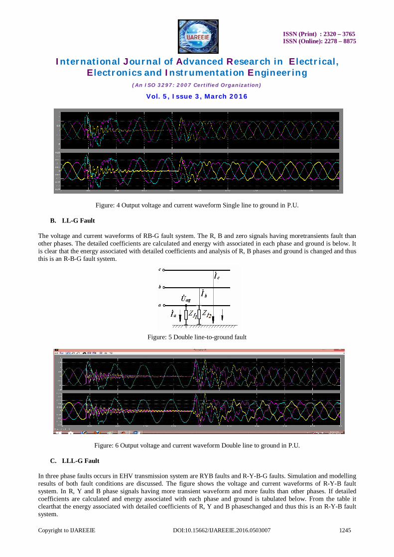
Figure: 6 Output voltage and current waveform Double line to ground in P.U.
C. LLL-G Fault
In three phase faults occurs in EHV transmission system are RYB faults and R-Y-B-G faults. Simulation and modelling results of both fault conditions are discussed. The figure shows the voltage and current waveforms of R-Y-B fault system. In R, Y and B phase signals having more transient waveform and more faults than other phases. If detailed coefficients are calculated and energy associated with each phase and ground is tabulated below. From the table it clearthat the energy associated with detailed coefficients of R, Y and B phaseschanged and thus this is an R-Y-B fault system.

ISSN (Print) : 2320 – 3765 ISSN (Online): 2278 – 8875
International Journal of Advanced Research in Electrical,
Electronics and Instrumentation Engineering (An ISO 3297: 2007 Certified Organization)
Vol. 5, Issue 3, March 2016
Copyright to IJAREEIE DOI:10.15662/IJAREEIE.2016.0503007 1246
Figure: 7 Triple line-to-ground fault
Figure: 8 Output voltage and current waveform Triple line to ground in P.U.
D. Single Line-Ground Fault at Input side
Here we have simulation on single line to ground fault occurs their one phase is short to the ground and the fault the impedance is not zero. When their output waveform shows the rise of current on L-G fault occur on overhead transmission line.
Figure: 9 L-G Fault waveform of currentat input side in P.U.
E. Double Line-Ground Fault at Input side
Now simulation and modelling on double line to ground fault occurs their two phases is short to the ground. When the magnitude of the faults current line are higher than the normal input current and the voltage are not change inmagnitude and the fault the impedance is not necessary zero and output waveform shows the gradually rise of current where 2L-G fault occur on EHV transmission line.
ISSN (Print) : 2320 – 3765 ISSN (Online): 2278 – 8875
International Journal of Advanced Research in Electrical,
Electronics and Instrumentation Engineering (An ISO 3297: 2007 Certified Organization)
Vol. 5, Issue 3, March 2016
Copyright to IJAREEIE DOI:10.15662/IJAREEIE.2016.0503007 1247
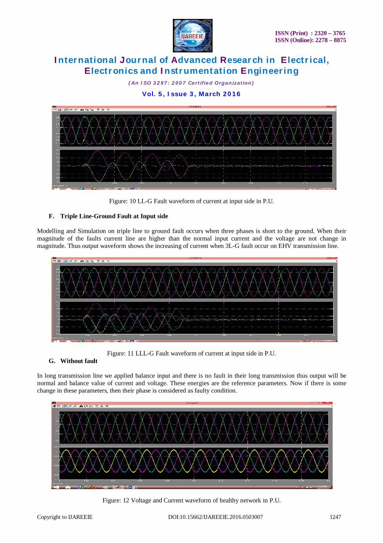
Figure: 10 LL-G Fault waveform of current at input side in P.U.
F. Triple Line-Ground Fault at Input side
Modelling and Simulation on triple line to ground fault occurs when three phases is short to the ground. When their magnitude of the faults current line are higher than the normal input current and the voltage are not change in magnitude. Thus output waveform shows the increasing of current when 3L-G fault occur on EHV transmission line.
Figure: 11 LLL-G Fault waveform of current at input side in P.U. G. Without fault
In long transmission line we applied balance input and there is no fault in their long transmission thus output will be normal and balance value of current and voltage. These energies are the reference parameters. Now if there is some change in these parameters, then their phase is considered as faulty condition.
Figure: 12 Voltage and Current waveform of healthy network in P.U.
ISSN (Print) : 2320 – 3765 ISSN (Online): 2278 – 8875
International Journal of Advanced Research in Electrical,
Electronics and Instrumentation Engineering (An ISO 3297: 2007 Certified Organization)
Vol. 5, Issue 3, March 2016
Copyright to IJAREEIE DOI:10.15662/IJAREEIE.2016.0503007 1248
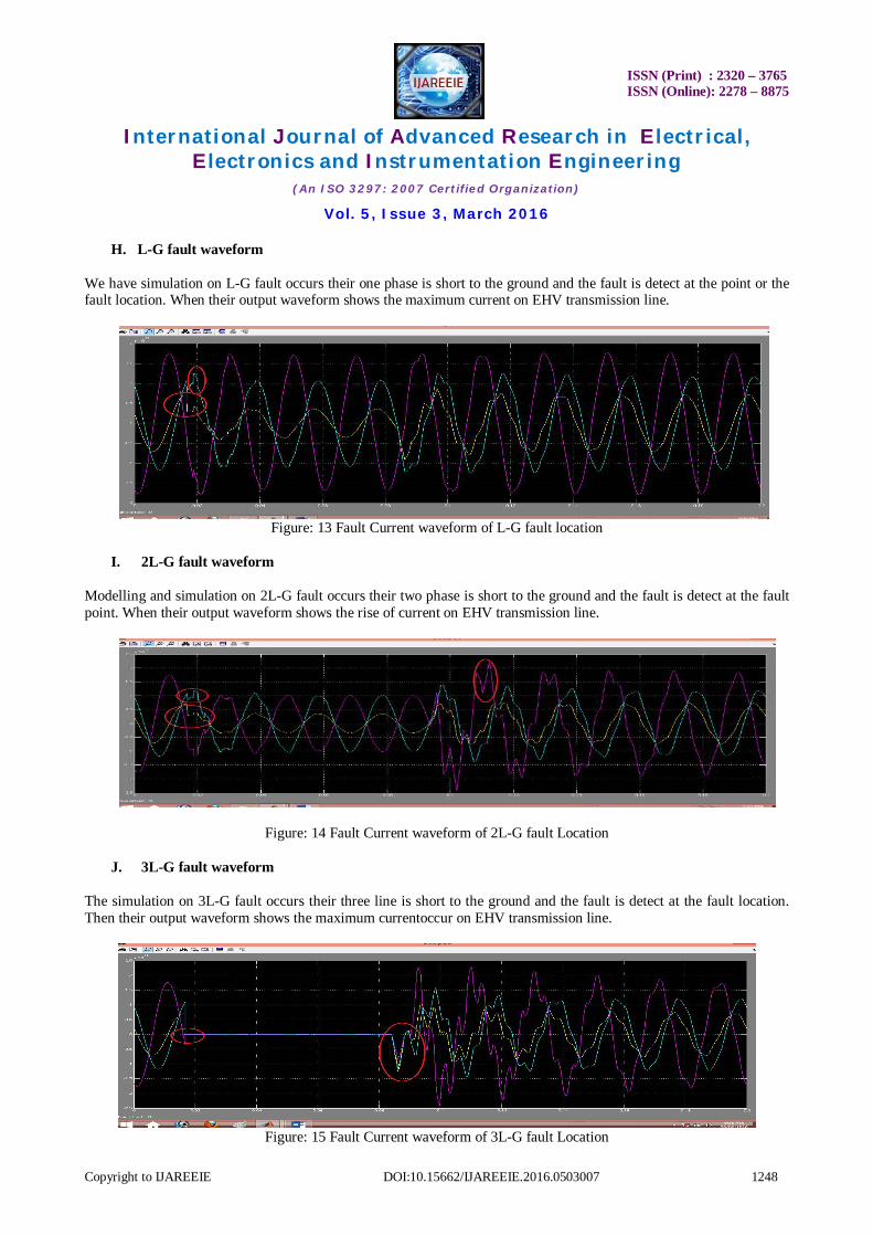
H. L-G fault waveform
We have simulation on L-G fault occurs their one phase is short to the ground and the fault is detect at the point or the fault location. When their output waveform shows the maximum current on EHV transmission line.
Figure: 13 Fault Current waveform of L-G fault location
I. 2L-G fault waveform
Modelling and simulation on 2L-G fault occurs their two phase is short to the ground and the fault is detect at the fault point. When their output waveform shows the rise of current on EHV transmission line.
Figure: 14 Fault Current waveform of 2L-G fault Location
J. 3L-G fault waveform
The simulation on 3L-G fault occurs their three line is short to the ground and the fault is detect at the fault location. Then their output waveform shows the maximum currentoccur on EHV transmission line.
Figure: 15 Fault Current waveform of 3L-G fault Location
ISSN (Print) : 2320 – 3765 ISSN (Online): 2278 – 8875
International Journal of Advanced Research in Electrical,
Electronics and Instrumentation Engineering (An ISO 3297: 2007 Certified Organization)
Vol. 5, Issue 3, March 2016
Copyright to IJAREEIE DOI:10.15662/IJAREEIE.2016.0503007 1249
V. RESULT AND DISCUSSION
Here we studies about earth fault have been carriedout for various locations along the EHV transmission line fordifferent types of the faults. Now we analysisanddetect the active power, reactive power, bus current and voltage of the long transmission line system at various types of fault condition. In each case the phase of the 440kv EHV transmission line forvoltage and current are changed and also theimpedance seen by the extra high voltage transmission line is not change and the whole modellingand experimental work are in MATLAB software.
VI.CONCLUSION
In this paper we studies faults locations on EHV transmission line parameter is convenient by using MATLAB software along with the Sim-power system toolbox in Simulink for detection and analysis of faults distance on 300 km/440 kV supply on long transmission line. The properties of traveling waves on EHVtransmission lines were discussed. NowEHV transmission line are line four types of fault namely L-G, LL-G, LLL-G and L-L-L faults have been Distance taken at 300 km into consideration into this simulation and experimental work and here many types of fault namely as single line ground fault, Double line to ground faults, Triple line to ground faults and L-L-L faults are detection and analysis has been show on this paper to their proposed work in MATLAB software.
REFERENCES
[1] Manju, Sooraj Maharana, Chandrakant Sharma, “Fault Analysis of Transmission Line Approach to MATLAB Simulation” Taraksh Journal of Web Services, Volume 1 Issue 1, 2014.
[2] Swapnil C. Naghate, Saurabh M. Dhuldhar, Ashvini B. Nagdewate, “Transmission line fault analysis by using MATLAB Simulation” IJESRT, pp no. 330-333, feb- 2015.
[3] Satish Karekar, Varsha Thakur, Manju, “A Novel Scheme of Transmission Line Faults Analysis and Detection by Using MATLAB Simulation.” International Journal of Engineering Research and General Science Volume 4, Issue 1, Pp no. 490-497,January-February 2016.
[4] D. V. Coury, and D.C Jorge, “Artificial Neural Network Approach to Distance Protection of Transmission Lines”. IEEE Trans. on Power Delivery, Vol.13, No.1, Pp. 102-108, 1998.
[5] A.NgaopitakkalPongchaisrikul, A.Kundakorn,“Analysis of characteristics of simultaneous faults in electrical power system using wavelet transform” In Proc. IEEE InternationalConf. on Sustainable Energy Technologies Pp.249-252,2008.
[6] PrinceJose, Bindu V.R,“Wavelet-Based Transmission Line Fauly Analysis” International Journal of Engineering and Innovative Technology (IJEIT) Volume 3, Issue 8, pp.55-60, February 2014.
[7] Shilpi Sahu, Dr. A. K. Sharma, “Detection of fault location in transmission Lines using WaveletTransform” Journal of Engineering Research and Applications Vol. 3, Issue 5, pp.149-151, Sep-Oct 2013.
[8] Smriti Kesharwani, Dharmendra Kumar Singh, “Simulation of fault Detection for protection of Transmission line using neural network” International Journal of Science, Engineering and Technology Research (IJSETR), Volume 3, Issue 5, May 2014
[9] P. Chiradeja and A. Ngaopitakkul, “Identification of Fault Types for Single Circuit Transmission Line using Discrete Wavelet transform and Artificial Neural Networks” Proceedings of the International MultiConference of Engineers and Computer Scientists Vol II IMECS, March 18 - 20, 2009, Hong Kong.
[10] Anamika Yadav, A.S. Thoke, “Transmission line fault distance and direction estimation using artificialneural network” International Journal of Engineering, Science and Technology Vol. 3, No. 8, pp. 110-121, 2011.
[11] Eisa Bashier M Tayeb, “Neural network approach tofault classification for high speed protective relaying”AmericanJournal of engineering research (AJER) volume-02, pp 69-75, 2013.
[12] Rajveer Singh, “Fault detection of electric power transmission line by using neural network”,Volume-02, Issue12, 2012. [13] T. B. Littler, d. J. Morrow, A.Kundakorn, “Wavelets for the Analysis and Compression of Power System Disturbances”, IEEE International
Conf. on Sustainable Energy Technologies Transactions on Power Delivery, vol. 14, pp. 358-364, Apr. 1999. [14] D. Das, N.K. Singh and A.K Singh, A.Kundakorn, “A Comparison of Fourier Transform and Wavelet TransformMethods for Detection and
Classification of Faults on Transmission Lines”, IEEE Power India Conference, NewDelhi Transactions on Power Delivery, Vol. 23, No. 4, October2008.