Embed Size (px)
Citation preview
-...,.~ l•~1i~- ..,,
_c\.- ,
~:::-J.;
~; ~-1'
~:~1
DESIGN OPTIMIZATION AND ENVIRG~MENTAL IMPACT STUDIES FORTHE ITAIPU.±. 600 kV HVDC LINES ArC ELECTRODE LINES
"
-~
~-~lJy
Por;...da, C. M. **Lojey, D. J.**Jadni, J. A.*it .
.~
4
This paper was in accordance with the stc:~' of the art, at the time of itspresentation, no changes having been intro.::uced for this publicati~n.
;:--,.,i~."
~.~~
-1t--,..;•~i
~i.J- ,.J.•• J
~.~
~-{J~
~.
"1.,.•
~1
-..
* Staff member of FURNAS** Staff member of Itaipu Study GroupThe above indications correspond to the t;;:18 of the paper preparationand not necessarily to the time of this reprint .
~=-,J
~j
J--~~~--'i
.~
i--"]~~J
,~-~-~
~~t-;=--,
"--,~- 1
!,-;f=~~~;~
,-5,
l-:0;~
1
~J
-;~~
-i
DESIGN OPTMIZATION AND ENVIROMENTAL IMPACT STUDIES FOR THE ITAIPU± 600 kV HVDC LINES AND ELECTRODE LINES
by
Peixoto, C. A. O.Portela, C. M.Lobley, D. J.Jardini, J. A.
The Itaipu Transmission System is composed of five transmission line circuits of which three are 800kV ·ac and two are ± 600 kV (bipolar) de. In 1979, a paper (2) reporting the design of the Itaipu 800kV ac lines was presented at the Sturly Committee 22 Colloquium on UHV lines. That paper dealt, inparticular, with the optimization of the line electro-mechanical design using computor aided designprocedures. These same procedures were followed in the design of the HVDC lines and therefore thispaper should be read in association with the earlier paper.
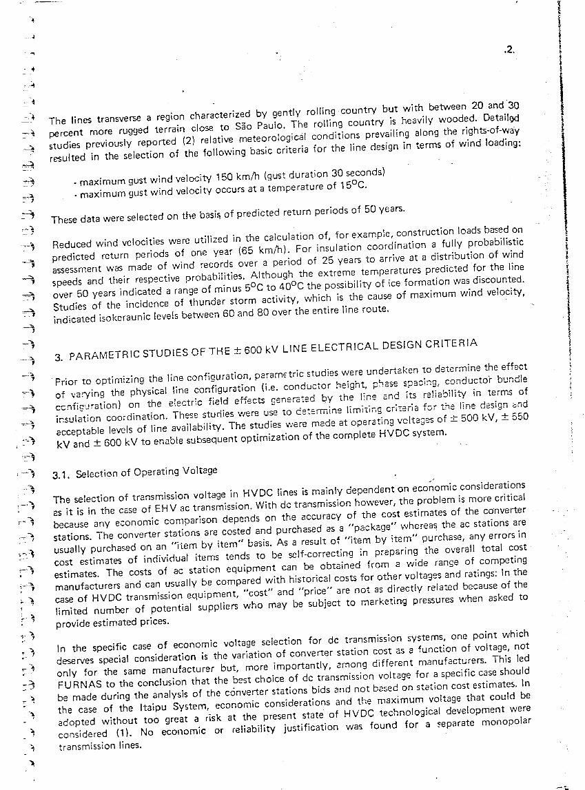
The two ± 600 kV bipolar lines interconnect the substations of Foz do Igua9u, situated close to theItaipu hydroelectric plant, and Sao Roque being the terminal station near the city of Sao Paulo. Thebipolar lines utilize two rights-of-way separated by approximately 30 km and follow the routes of thethree Itaipu 800 kV EHV lines maintaining a separation between any hvo rights-of-way in the order of10 km. The rights-of-way are arranged, as shown in Figure 1 and 'Nere selected to reduce to aminimum the possibility of common-mode of failure of an,v two lines.
60Hz
IIOkm
~Hz I( HYDe)
Fig. 1
~1.-)
F1~-~1:=~"~1,.c--c-~: 1
:..-1,
The lines transverse a region characterized by gently rol!ing country but with between 20 and 30percent more rugged terrain close to Sao Paulo. The rolling country is heavily wooded. Detaill]dstudies previously reported (2) relative meteororogical conditions prevailing along the rights-of-wa'yresulted in the selection of the following basic criteria for the line design in terms of wind loading:
. maximum gust wind velocity 150 km/h (gust duration 30 seconds)- maximum gust wind velocity occurs at a temperature of 150C.
Reduced wind velocities were utilized in the calculation of, for example, construction loads based onpredicted return periods of one year (65 km/h). For insulation coordination a fufty probabilisticassessment was made of wind records over a period of 25 years to arrive at a distribution of windspeeds and their respective probabilities. Although the extreme temperatures predicted for the lineover 50 years indicated a range of minus 50C to 400C the possibility of ice formation was discounted.Studies of the incidence of thunder storm activity, which is the cause of maximum wind velocity,indicated isokeraunic levels between 60 and 80 over the entire line route.
Prior to optimizing the line configuration, parametric studies were undertaken to determine the effectof \'a:ying the physical line configuration (i.e. conductor heigh~ phc5e spacing, conductor bundlecC1ifiguration) on the electric field effects generc-red b,v the line end its reliability in terms ofir.sulation coordination. These studies \fIere use to de:;:;rmine limiting crirsria for the line design endacceptable levels of line availability. The studies were made at operating voltages of ± 500 kV, ± 550kV and ± 600 kV to enable subsequent optimization of the complete HVDC system.
/
The selection of transmission voltage in HVDC lines is mainly dependent on economic considerationsas it is in the case of EHV ac transmission. With dc transmission however, the problem is more criticalbecause any economic comparison depends on the accuracy of the cost estimates of the cO'nverterstations. The converter stations are costed and purchased as a "package" whereas the ac stations areusually purchased on an "item by item" basis. As a result of "item by item" purchase, any errors incost estimates of individual items tends to be self-correcting in preparing the overall total costestimates. The costs of ac station equipment can be obtained from a wide range of competingmanufacturers and can usually be compared with historical costs for other voltages and ratings: In thecase of HVDC transmission equipment, "cost" and "price" are not as directly related because of thelimited number of potential suppliers who may be subject to marketing pressures when asked toprovide estimated prices.
In the specific case of economic voltage selection for dc transmission systems, one point whichdeserves special consideration is the variation of converter station cost as a function of voltage, notonly for the same manufacturer but, more importantly, among different manufacturers. This ledFURNAS to the conclusion that the best choice of dc transmission voltage for a specific case shouldbe made during the analysis of the converter stations bids and not based on station cost estimate5. Inthe case of the Itaipu System, economic considerations and the maximum voltage that could beadopted without too great a risk at the present state of HVDC technological development wereconsidered (1). No economic or reliability justification was found for a ~eparate monopolartransmission lines.
,"~ "~.:~-;.;
-- y
"~1~- ;.~J.----.- ;..:
=-1~ rallel with the extensive system studies a very detailed investigation of line design was carried oytI: :termine the most economical design for each of the thre: possi.ble voltages. Based on theset . um line designs the present worth costs for the lines combined with the present worth for theopt1m V f dluated cost of the station proposed by the bidders was obtained. A voltage of 600 k was oun totVa most economical overall choice although .it was not the most economic system voltage for allbe . fconverter station manu acturers.
This paper concentrates on the studies which were made for the ± 600 kV transmission line voltagefinally selected on the above basis' for the Itaipu System. .
The occurrence of a ground fault on one pole of a HVDC line results in an oveNoltage on theassociated healthy pole. A principal objective in the insulation design of a HVDC line is to reduce thepossibility that this overvoltage will produce a fault on the second po.le resulting in a bi?ole outage.The actual value of the overvoltage is dependent on many factors outSide the scope of this paper. Forthe parametric studies of the line insulation coordination values of 1.7 pu, 1.8 pu, 1.9 pu and 2.0 puwere considered. Based on detailed studies of the overall HVDC system the converter stations werefinally specified such that this overvoltage would be limited to a maximum value of 1.8 pu. The linewas designed to provide acceptable low risks of failure to an overvoltage of 1.8 pu an.d the possibilityof pole fault occurrence rate limited to a value which v.'Quld obviate the possibility of independent butcoincident fault on any two poles. This was achieved by the provision of adequate insulator stringlength to avoid operating voltege f!cshO\ter and shielding to reduce the lightning outage incident rate.
Unlike EHV ac lines, the occurrence of a single pole to ground fault due to lightning is not significant,in terms of system performance, on the Itaipu System which utilizes two bipolar lines. A transient lineoutage of a pole results in the current in that pole being brought to zero and returned to the pre-faultvalue by converter control action after elimination of the fault. The duration of the current· reductioncan be very short in comparison to reclose "dead-times" on ac systems. The fault can be eliminated bycurrent reduction in a matter of milliseconds and, if necessary, multiple attempts made to re-establishtransmission. Even in the case that restart is not successful at full voltage it can be attempts made tore·establish transmission. Even in the case that restart is not successful at full voltage it can beattempted, with a very high possibility of success, at reduced voltage. On the Itaipu System provisionis made for restart at 70 percent of normal operating voltage if, for example, the fault has resultedfrom insulator pollution thus avoiding a total loss of transmission capacity on the faulted pole. In thecase of serious damage, resulting in a permanent outage on a pole, the system can be operated in amonopolar mode using ground return and increasing the power transmitted on one pole or byparalleling the converters of one bipole with those of the other and operating the healthy bipole line atdouble current. Another factor which reduces the significance of line pole faults is that the faultcurrent is unlikely to cause insulator damage or heavy ionization at the faulted insulator string.Although these considerations reduce the irrplication of line pole faults it is naturally desirable tolimit their incidence to the minimum to avoid unnecessary disturbances on the power system andreouce the possibility of independent but coincident faults on separate poles.
The lightning performance of the Itaipu lines was analysed considering lightning stroke to theconductors (direct strokes) and to the structure (indirect strokes). Outages can be minimized orpractically eliminated by selecting a suitably small protective angle and making the distance betweenthe conductor and overhead shield wire as small as possible. This is counterbalanced, in terms ofindirect stroke protection, by the reduction of clearance between the shield wires and the conductorsat mid-span. A single shield wire was first considered which offered adequate shieldir'lg against directstrokes but required a distance of some 16 meters between it and the conductors. This shield wireposition was found to be inadequate in terms of indirect stroke protection. Application of two shieldwires demonstrated a reduction of the outage rate, at very little increase in cost, by an order ofmagnitude and a decision was taken to utilize two overhead shield wires. Optimizing the position ofthe shield wires by positioning as close as possible the conductor resulted in the lower outage rate ofapproximately one outage per 100 km per year of which the majority result from indirect strokes.
As previously explained two aspects controlled the insulation coordination of the Itaipu HVDC lines:insulation for operating voltage and the overvoltage surges on the healthy pole of a bipolar lineresulting from faults on the other pole (caused by lightning or operating voltage flashover). Operatingvoltage determined the length of the insulator string and the minimum total creepage distance over theinsulator surface. Under certain circumstances the operating voltage determines the air-clearances with"1" strings under sustained high wind velocities. For the Itaipu project the creepage distance wasfound to be satisfactory on operating HVDC schemes were examined in terms of the contaminationconditions expected in the area transversed by the Itaipu lines. In the region of Sao Paulo pollutionhas been ciassed as moderate but is light for the majority of the route. For the majority of the route,the expected poi!utents a~e fertilizers or air-borne dust. From 2;:'-2,2::,,; p-:~:::':s, ·'r.,h;~h do notexperier.ce salt spray contamination, it was noted that successful operation hcd bsen achieved withspecific creepage distances of between 23 and 27 mm/kV. These figures included the Nelson RiverProject in Canada with 23 mm/kV. Manufacturers information indicated that suitable HVDC glassinsulators wouid be available in Brazil with a creepage distance of 510 mm which resulted in 25.5mm/kV if thirty insulators were selected from suspension strings.6nj)J.!:i'::JJ?!ion string comprisin§-3Qinsulators was adopted noting that the possibility existed to manufacture a HVDC glass insulator inBrazil with a creepage distance of 540 mm resultillgin an additioriarm~~gin of security.
Another aspect of insulator performance which was examined was their reliability. Information fromcertain operating HVDC lines indicated higher than expected failure rates for insulators of both glassand porcelain construction. As the information available did not allow a full analysis of the problem, itwas decided to initiate a program of investigation with cooperation between FURNAS, ENEL,CEPEL, CESI, ELETROVIDRO and CERAVER. The program of investigations is still in progress andis concentrated on determining the possible causes of failure of HVDC insulators to permit a choice tobe made between porcelain and glass and enable an adequate purchasing specification to be preparedwhich will guarantee the performance of the insulators in service. It is hoped that the results of theinvestigations will be reported in full on completion however, preliminary indications are that thefactors which are most important in determining satisfactory operation of a HVDC insulator arevoltage distribution on the string and the temperature attained by the insulator during operation. Onthis basis a specification was prepared allowing an option of either glass or porcelain insulators andrequiring the potential manufacturers to perform tests which included thermal stability and ionicmigration among others.
-~)'
I~.~
;:..--=--- .'Y
...,~
_-1.: ..,
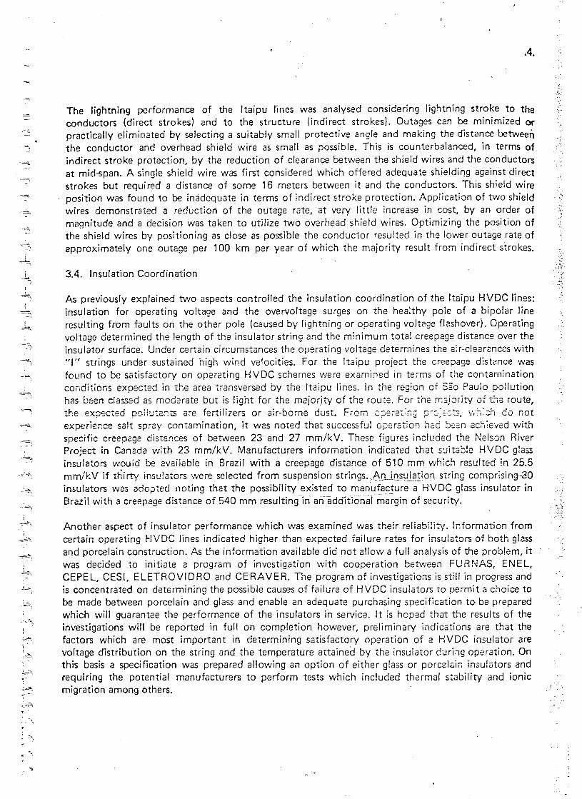
The studies of insulation coordination involving "switching surges" were based on the previouslymentioned overvoltage resulting on a healthy pole with a maximum value of 1.8 pu. Th~ overvoltagewas treated as a variable with a maximum value of 1.8 pu based on fault locBt; on and thecorresponding overvoltage profile along the healthy pole. Initial studies indicated that ''1'' insulat6rstrings would represent a less expensive overall solution than "V" strings under ,,:ly possiblemechanical or electrical condition. The insulation coordination was carried out using a fullyprobabilistic treatment of overvoltage and variation of insulator swing angle with wind combined withdistribution of atmospheric pressure, temperature and humidity. The results of the analysis predict aline risk of failure of 1 :500 for the structure (including guy) configuration selected. Based on lightningoutage rate of one failure/100 km/ year approximately 8 to 10 lightning faults would be expected perbipole year giving a probability of a fault on the second pole in the region of one in 50 years, which isalso the expected life of the lines. The distance between poles was determined by consideration ofthe operating voltage withstand and the maximum insulator swing to the structure leg under anextreme wind velocity with a return period of 25 years and taking into consideration the minimum ofwind to weight span ratios expected along the line. The final distance between poles of 15.4 meterswas also selected considering the minimum conductor diameter, bundle configuration and the effect ofthese parameters on the initiation of conductor corona.
Tl:e final tower head design inclurling the positioning of the structure guys W2.S specified in terms ofthe clearance dimensions shown in Figure 2.
0 0~ ,..;0 11-10. 0!XlN
W-llDCl:a.:Cl::>
STRUCTURE TYPES G81/G82/G83lGUYED)Fig. 2
It should be emphasized that the clearances are not b2sed on ~'code" or specific wind speed values butwere selected to describe the head configuration V\o71ichresulted in the best performance in theinsulation coordination studies and allow the structure designers certain liberty to optimize thestructure design or guy locations within the imposed lil7lits.
_~1--~
---'I
~~')
.,.~",- .'
.=~ ;
.=-~
4'. ,-~;=- 3
;
-:--~
~~"'~
The primary object of the studies of field strength were to determine the minimum conductor toground distance at mid-span noting that insulatiof) coordination also influence this dimension.
Two conditions of extreme sag can occur on the ltaipu lines. Firstly, with the bipole transmitting itsnominal maximum rating of 3150 MW during which the conductor temperature will reach 650C withan ambient temperature of 490C. Secondly, an emergency condition where one bipolar line is out ofservice and the second line is transmitting double current as a result of paralleling the two ± 600 kVbipole converters. Under this emergency condition the conductor temperature is allowed to reach950C which would occur at an ambient temperature of 300C. The electric field resulting from HVOClines at ground level tends to be higher than would be expected from similar EHV ac lines. The effectsof the dc field however, are less pronounced (3) because the dc field does not result in a flow ofdielectric current due the capacitive effect as does an ac field. A maximum field strength of 40 kV 1mwas selected as a limiting criteria considering space charge and without wind. This field strengthcorresponds to a level of sensation classified as "disturbing" in subjective field and laboratory tests (3)when the persons involved were isolated by standing on a sheet of high resistivity rubber resulting inthe person being elevated to the maximum potential possible. In the same tests it was noted that whenusing normal shoes no physical sensation was observed in a field of 40 kV 1m. With even low windvelocities of 1 to 2 meters/second the maximum value of the field strength drops to low values (15kV 1m without space charge) due to dispersion of the space charge. Under the emergency condition ofdouble current with spans of over 600 meters a maximum sag increase of 110 cm can be expected anda field strength of 45 kV 1m without wind would result. It was judged that, cons(dering the lowprobability of this condition, the higher value of field strength would be acceptable particularly as thepossibility of zero wind velocity is extremely unlikely and any \\/ind whatsoever increases the groundclearance and disperses the space charge thereby reducing tne field strsr;gth.
It was decided that it wculd be undesirable to operate a HVOC line (particularly the first in Brazil) inconditions of generc:lized visual corona in all but extremely poor weather conditions. A criterion wasadopted that the corona gradient on the selected conductor should be 10 percent below the criticalgradient at which generalized corona would be expected under weather conditions which would occur(or be more unfavorable) less than 10 percent of the time. The calculation was made assuming bipolaroperate which represented the worst case condition. The critical gradient was based on calculationgiven in reference (5). Corona on the overhead shield wires was limited by a similar criterion althoughthe margin between the gradient of generalized corona and conductor gradient was reduced to 5percent considering that shield wire corona is only expected adjacent to the structure where the shieldwire is at its highest point from ground level. The calculation was made at a point 10 meters from theshield wire attachment point with atmospheric conditions which would be expected to occudor lessthan 50 percent of the time. The worst operation condition considered for shielcl wire corona was withunbalanced voltage operation (300 kV 1600 kV) being worse than bipolar operation. In fact monopolaroperation represents the worse condition but only occurs for short operating periods and wasdiscounted.
Unlike EHV ac transmission lines the radio interference (RI) generated by HVOC transmission Jines ispred<?minant in fair weather. Foul weather does not result in the characteristic increase in RI (or TVI)associated with EHV ac lines. The HVOC lines on the other hand, can generate more intense RI during
;
--~'~i-'{
-~-~~
•._-~:.
- '1"~~I
~lj
4:
fair weather than similar EHV ac lines but, the "quality" of the interference generated by HVDC linesis considered less annoying. A criterion for R I was adopted which allowed a maximum signal to noiseratio of 17 to 20 dB at the edge of the right-of-way referred to a signal reference level of 1microvolt/meter at 1 MHz which corresponds (3) to a class of reception between "noise evidentwith inteligible reception" to noise detectable with good reception". This criterion used !Jlcombination with requirements of the Brazilian Ministry of Communications Standard NTC 19A for'aminimum signal of 66 dB for cities with populations between 2500 and 10000 inhabitants resulting inan acceptable noise level at the edge of the right-of-way between 46 t~4~_.dJLduring fair weather.
-~.,._,~--
For audible noise (AN) 'a criterion of 40 dBA at the edge of the right-of-way to be measured with anaudible noise meter of the standard American type with a sensitivity of class A neglecting ambientnoise. It should be noted that even with an ambient noise level of 40 dBA the total noise level onlyrises to 43 dBA. This noise leve! corresponds to subjective evaluation (3) between "moderate" and"evident".
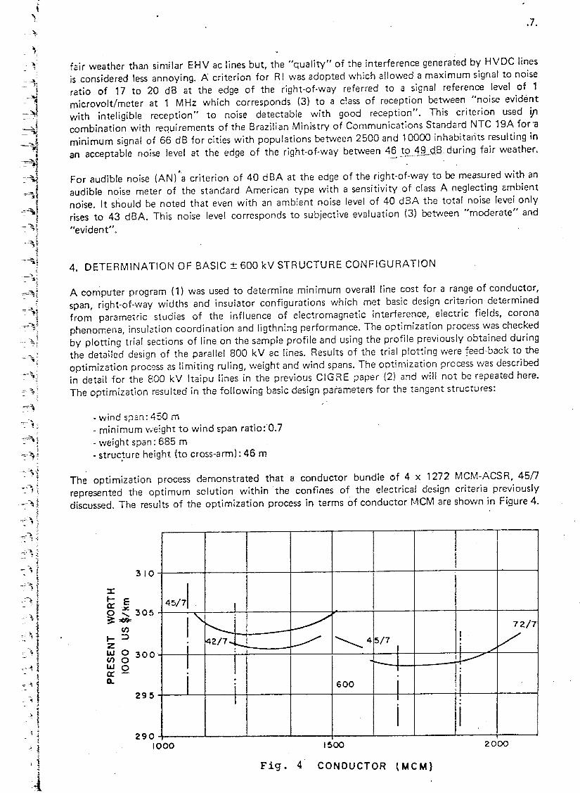
A computer program (1) was used to determine min imum overall fine cost for a range of conductor,span, right-of-way widths and insulator configurations which met basic design criterion determinedfrom parametric studies of the influence of electromagnetic interference, electric fields, coronaphenomena, insulation coordination and ligthning performance. The optimization process was checkedby plotting trial sections of line on the sample profile and using the profile previously obtained duringthe detailed design of the parallel 800 kV ac lines. Results of the trial plotting were feed-back to theoptimization process as limiting ruling, weight and wind spans. The optimization process was describedin detail for the 800 kV Itaipu lines in the previous CIG RE paper (2) and will not be repeated here.The optimization resulted in the following basic design parameters for the tangent structures:
- wind spcn: 450 m· minimum weight to wind span ratio: 0.7· weight span: 685 m• structure heiaht (to cross-arm): 46 m. ~
The optimization process demonstrated that a conductor bundle of 4 x 1272 MCM-ACSR, 4Snrepresented the optimum solution within the confines of the electrical design criteria previouslydiscussed. The results of the optimization process in terms of conductor MCM are shown in Figure 4.
310
~ E 45/71o ~ 305;:#F
(J')•.. ::>zW 0 300(J')OWo0::Q.
2901000
. ,."'........JI.:.---,i~J;
, '-~~:;"-1
i~~
I~;-=-=l
~--- --I, '
~~i. ~ .:.!-~
;-~;~1-.- :;,
Based on previoulsy described foundation type testing and design studies carried out for the 800 kV aelines (1) and bearing in mind the proximity of the HVDC line to the 800 kV lines it was concludedthat the same type of foundation would represent the best solution for the HVDC lines. Thefoundation use grillage for the central mast and inclined grillage for the guy anchors. Two standar.dtypes of foundation will be employed characterized by soil capacities of 1 kg/cm2. Less than 5 percen'tof the structures should require foundations of special design or special back-fill material in the case ofguy anchors.
A similar family of structure developed for the 800 kV ac transmission lines 'was adopted for theHVDC lines based on the optimized tangent and small suspension angle structures (2).
The Itaipu HVDC system has an emergency condition which involves operating in the monopolar'mode using ground return. In addition, it is necessary to provide a ground point for the neutral of theconverters. These two functions are achieved by providing a ground electrode with capacity todissipate the ground current without excessive voltage or temperature rise. The ground electrode hasto be located some distance from the converter stations and interconnected with the stations by atransmission line. Little has been written about the design of these electrode lines presumably becausethey are usually of simple, low voltage, construction. On the ltaipu System, the length of the electrodelines of up to 50 km, coupled with the high currents involved (2600 A in monopolar operation), and ahigh isoceraunic level stimulated more detailed investigations than has perhaps been necessary in thepnsL
At Foz do 19uac;:;utV'lO ground electrodes are located, in two separate locations approximately 15 kmfro~ the converter ste:tion 2:10 in directions different from those transverssc by t:-:e ± 6CQ kV Iir.es.At Saa Roque the two electrodes are located at the same site some 50 km from the conver:er st3tionand adjacent to the right-of-way of one of the ± 600 kV lines. At S. Roque at least one of theelectrode lines could therefore, be mounted on ± 600 kV structures. Mounting the electrodf. line onthe main-line structure brings advantage in reducing telephone interference by physicallycOflcentrzting the two lines and primary sources of interference on one right-of-way. However, thissolution would require additional filters of complex design on the electrode line to avoid interferencewith the main-line PLC. The cost of these filters eliminated any potential advantage gained bymounting the electrode line on the main-line structures. To obviate the need for electrode line PLCfilters it was found necessary to maintain a separation between it and the main-fine in the order of 1km. For these reasons it was decided to provide each electrode line, both at Foz do Iguac;:;uand SaoRoque, with separate structures built on separate rights-of-way.
Of particular concern in the design of the electrode lines was the ability of the line insulation toself-extinguish dc arcs following flashover due to lightning or any other cause. When a fault occurs onthe electrode line, part of the ground return current flowing at the time of the fault is transferred toground via the fault path. It is evident that a dc current transferred to ground via the fault path willtend to maintain the fault arc. This continuous fault would be difficult to detect (bacause the objetcof the line is to transfer current to ground) and could be dangerous to persons in the vicinity of thefault not to mention damage that would be causerl to the electrode line insulators and structures. Evenif the fault could be detected the only way of interrupting the fault current would be by supressingthe main-line current to zero by converter control action. This would result in a transient main circuitoutage. It is important to remember that, although the electrode line is of a relatively simpleconstruction, it is fundamental to the operation of the HVDC system. The electrode lines will beconstructed using tvvo conductors each separately insulated to enable the continuity of the circuit tobe monitored and to decrease the possibility that continuity could be lost.
-~"'~ -J ,1-- -"13
-.•.•.~---] I -~ <t----,,:~
"l I t-1 Zi W
--"'~ 0::-j 0::::>U
-= :j t-~::J.
...J"l ::>
<t~><, ~ ~!
c=~ i,~4."..-,21.•
i
=~I=:' Ii--,:=-c'j I
1;
--,~
~, !I
~ tI"'- I1~
'" ~J
f-",;
-.., !~ J-~<
r),
2
}
)
~
j~
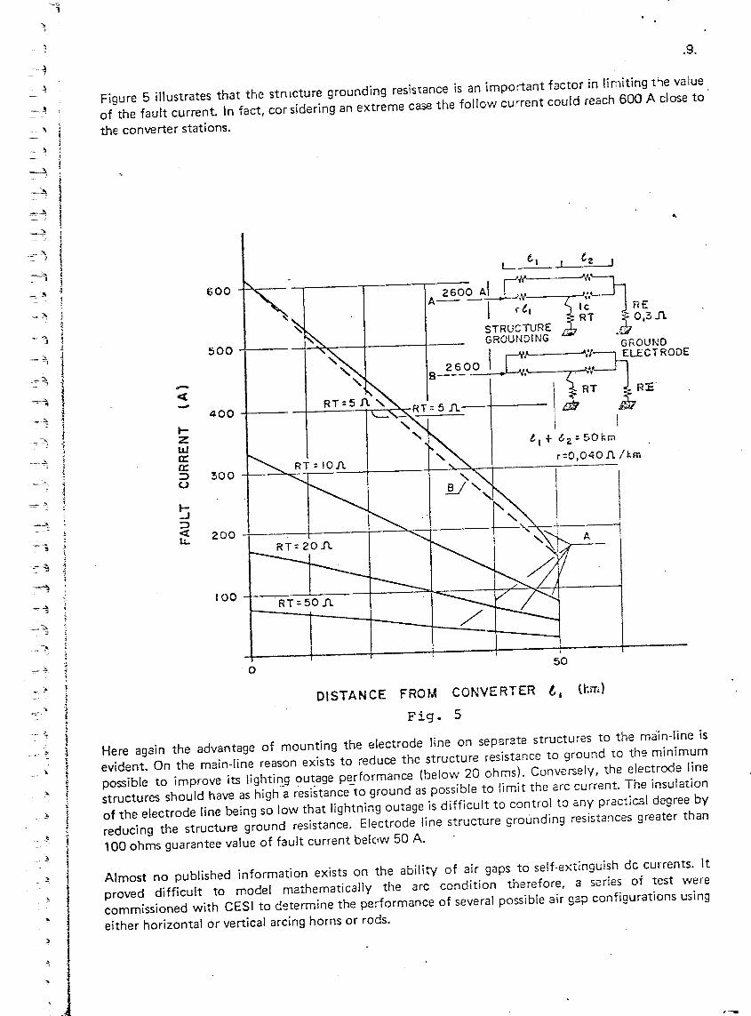
Figure 5 illustrates that the stnlcture grounding resistance is an important factor in limiting t.,e valueof the fault current. In fact, cor sidering an extreme case the follow current could reach 600 A close tothe converter stations.
DISTANCE FROM CONVERTER l. lkm)
Fig. 5
Here again the advantage of mounting the electrode line on separate structures to the main-line isevident. On the main-line reason exists to reduce the structure resistance to ground to the minimumpossible to improve its lighting outage performance (below 20 ohms). Conversely, the electrode linestructures should have as higha resistance-to ground as possible to limit the arc current. The insulationof the electrode line being so low that lightning outage is difficult to control to any practical degree byreducing the structure ground resistance. Electrode line structure grounding resistances greater than100 ohms guarantee value of fault current belctw 50 A.
Almost no published information exists on the ability of air gaps to self-extinguish dc currents. Itproved difficult to model mathematically the arc condition therefore, a series of test werecommissioned with CESI to determine the performance of several possible air gap configurations usingeither horizontal or vertical arcing horns or rods.
In the following Table the results of these tests are summarized. The test results demonstrated thatvertical arcing horns wi~h a gap of 20 em can reliably self-extinguish arcs of 440 A.
Maximum Current for which ArcSelf-Extinguished (A)
50105320
VerticalArcing Horns
440560
340565
HorizontalArcing Horns
This was a very encouraging result because prior to the tests very real doubts existed that such shortgaps could be reliably employed. A vertical gap of 20 cm allows a simple line construction using twostandard suspension insulators per conductor mounted on concrete poles with steel cross-arms.
It may seem strange to discuss "insulation coordination" of a line which, as described previously, wil!have an insulator arc gap of only 20 cm to provide self-extinguishing characteristics to dc faultcurrents. However, coordination is necessary to guarantee the self-extinguishing characteristics of thegap. The electrode line is subject to overvoltages when faults occur on the main-line and must alsosupport a continuous dc operating voltage. Utilizing two suspension insulators give an impulsewithstand of 210 kV. This value compares with the withstand of 20 cm gap of 8 sigma (sigma equal to3 percent) which is more than adequate. In terms of switching surge, considering their 60 Hz peakwithstand two insulators give a withstand of 10 sigma (sigma equal 5 percent) in comparison to the 20cm gap. The selection of two insulators gives excellent coordination with the 20 cm gap necessary togive the complete insulator/gap combination configuration the self-extinguishing properties of the gap.Two insulators are also adequate to withstand the continuous dc operating voltage in terfl'S of leakagedistance with a continuous voltage of 5 kV. In fact one insulator would serve for all of the aboveconditions but would not coordinate with the 20 cm gap. The second insulator also gives addedreliability that should an insulator fail, the electrode line can continue to serve its function ofmaintaining a ground point under normal operating condition and ground return with monopolaroperation provided no system disturbance occurs. Other insulation coordination considerations of theelectrode line were based on normal Brazilian distribution practice. The ground clearance at mid-span,for example, was set at 6.0 meters.
Specifications have been issued for bid or orders places for all the principal materials for the firstbipole line which is scheduled to enter in service in April 1983. The second bipole will enter in serviceapproximately two years later.
1. Peixoto, C.A.O . "ltaipu 6300 MW HVDC Transmission System Feasibility and PlanningAspects" . Symposium on Incorporating HVDC Power Transmission into System Planning·-
.; Phoenix, Arizona, USA, March 1980.~l
2. Fernandes, D., Santiago, R.C., Lobley, D.J., Mello, J.C.P. de - "Optimized EletromechanicalDesign for the Itaipu 800 kV Transmission Lines" . CIG Rt Study Committee 22 Colloquium onUHV Lines - Siena, Italy 1979.
5. Tikhodeyev and others - "Selection of Conductors and their Configurations for DC Lines withAllowance for Corona Losses, Radio Interference: Methods of their Measurements" - Proceedingsof the Symposium on HVDC Power Transmission - The Joint American-Soviet Committee,Leningrad, USSR, April 7-15,1976.