Embed Size (px)
Citation preview
Voids in Materials © 2015 Elsevier B.V.http://dx.doi.org/10.1016/B978-0-444-56367-5.00007-5 All rights reserved. 131
CHAPTER 7
Applications7.1 INTRODUCTION
Voids are ubiquitous in all natural and engineered materials. Different terms have been used to designate this void volume. This absence of material, which is what a void is, brings along with it very interesting and broad functionalities to the materials containing them. A few terms that we have used to name this “empty space” are void, vacancy, porosity, free volume, cell, cell structure, and hollow.
Just as widespread as voids are the applications that exploit them. When most of us think of this topic, foams and more specifically, polymer based foams immediately come to mind because they surround us in our daily lives. Car and furniture cushions, sponges, packaging material, insulation for coolers and construction, carpet backing, acoustic tiles, shoe insoles (Klempner and Frisch, 1991), etc., all are polymer foams. One cannot mini-mize the material design and testing that goes into these seemingly mun-dane applications. In most applications, the foams are highly engineered and have microstructures designed specifically to meet stringent design require-ments. The materials and products require extensive testing and evaluation of properties such as compression, fatigue, thermal conductivity, heat capac-ity, etc. In addition to the characteristics of foams in our daily life, even more highly engineered foams go into protecting life and equipment in harsh temperature and pressure environments as well as biomedical and drug delivery applications.
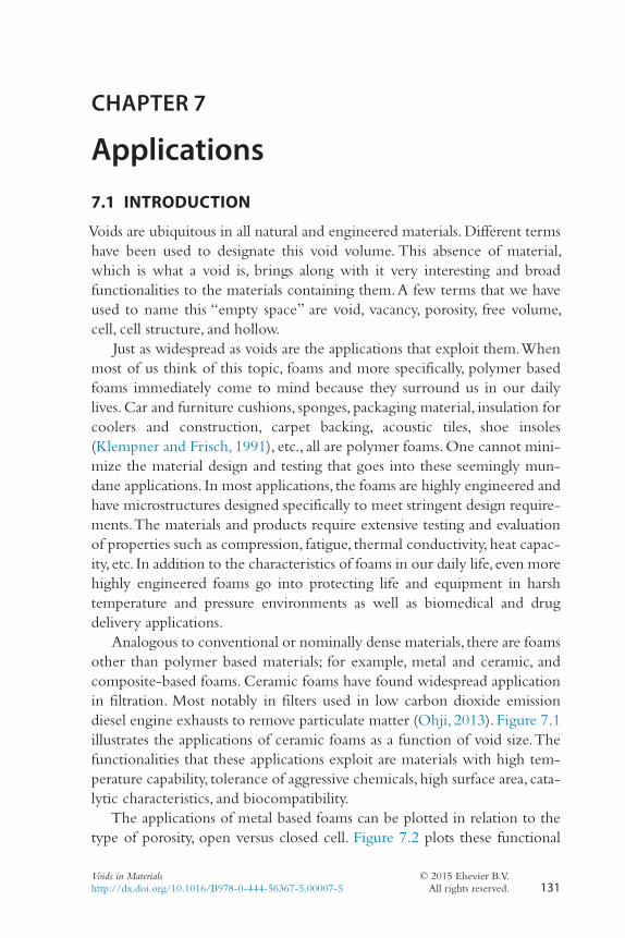
Analogous to conventional or nominally dense materials, there are foams other than polymer based materials; for example, metal and ceramic, and composite-based foams. Ceramic foams have found widespread application in filtration. Most notably in filters used in low carbon dioxide emission diesel engine exhausts to remove particulate matter (Ohji, 2013). Figure 7.1 illustrates the applications of ceramic foams as a function of void size. The functionalities that these applications exploit are materials with high tem-perature capability, tolerance of aggressive chemicals, high surface area, cata-lytic characteristics, and biocompatibility.
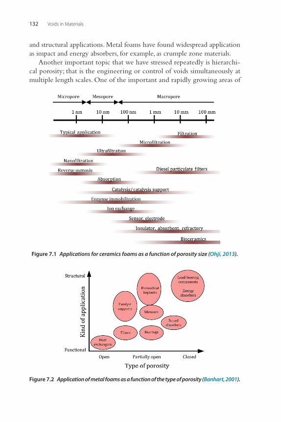
The applications of metal based foams can be plotted in relation to the type of porosity, open versus closed cell. Figure 7.2 plots these functional
Voids in Materials132
and structural applications. Metal foams have found widespread application as impact and energy absorbers, for example, as crumple zone materials.
Another important topic that we have stressed repeatedly is hierarchi-cal porosity; that is the engineering or control of voids simultaneously at multiple length scales. One of the important and rapidly growing areas of
Figure 7.1 Applications for ceramics foams as a function of porosity size (Ohji, 2013).
Figure 7.2 Application of metal foams as a function of the type of porosity (Banhart, 2001).
Applications 133
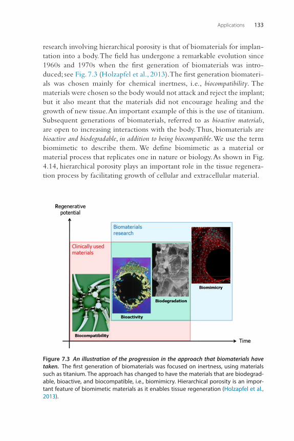
research involving hierarchical porosity is that of biomaterials for implan-tation into a body. The field has undergone a remarkable evolution since 1960s and 1970s when the first generation of biomaterials was intro-duced; see Fig. 7.3 (Holzapfel et al., 2013). The first generation biomateri-als was chosen mainly for chemical inertness, i.e., biocompatibility. The materials were chosen so the body would not attack and reject the implant; but it also meant that the materials did not encourage healing and the growth of new tissue. An important example of this is the use of titanium. Subsequent generations of biomaterials, referred to as bioactive materials, are open to increasing interactions with the body. Thus, biomaterials are bioactive and biodegradable, in addition to being biocompatible. We use the term biomimetic to describe them. We define biomimetic as a material or material process that replicates one in nature or biology. As shown in Fig. 4.14, hierarchical porosity plays an important role in the tissue regenera-tion process by facilitating growth of cellular and extracellular material.
Figure 7.3 An illustration of the progression in the approach that biomaterials have taken. The first generation of biomaterials was focused on inertness, using materials such as titanium. The approach has changed to have the materials that are biodegrad-able, bioactive, and biocompatible, i.e., biomimicry. Hierarchical porosity is an impor-tant feature of biomimetic materials as it enables tissue regeneration (Holzapfel et al., 2013).
Voids in Materials134
In addition to foams, we discuss other applications of voids in materials. These applications may not be obvious, but they take advantage of voids at some level for functionality. As such we present functionality in this chapter based upon length scale for a specific application.
7.2 MACROSCALE VOIDS7.2.1 HoneycombEverybody knows what a honeycomb is. It is the engineered structure that bees make of beeswax to store honey. It turns out that the hexagonal form of stacking results in the most compact structure. It can be easily shown that hexagonal packing will result in 90.6% packing efficiency. In engineering, we call any structure resembling honeycomb made by bees a honeycomb.
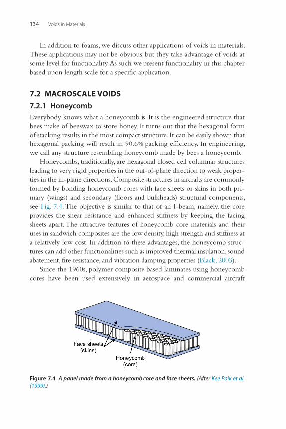
Honeycombs, traditionally, are hexagonal closed cell columnar structures leading to very rigid properties in the out-of-plane direction to weak proper-ties in the in-plane directions. Composite structures in aircrafts are commonly formed by bonding honeycomb cores with face sheets or skins in both pri-mary (wings) and secondary (floors and bulkheads) structural components, see Fig. 7.4. The objective is similar to that of an I-beam, namely, the core provides the shear resistance and enhanced stiffness by keeping the facing sheets apart. The attractive features of honeycomb core materials and their uses in sandwich composites are the low density, high strength and stiffness at a relatively low cost. In addition to these advantages, the honeycomb struc-tures can add other functionalities such as improved thermal insulation, sound abatement, fire resistance, and vibration damping properties (Black, 2003).
Since the 1960s, polymer composite based laminates using honeycomb cores have been used extensively in aerospace and commercial aircraft
Figure 7.4 A panel made from a honeycomb core and face sheets. (After Kee Paik et al. (1999).)
Applications 135
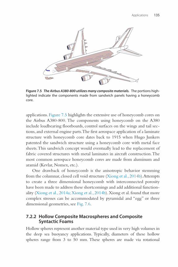
applications. Figure 7.5 highlights the extensive use of honeycomb cores on the Airbus A380-800. The components using honeycomb on the A380 include loadbearing floorboards, control surfaces on the wings and tail sec-tions, and external engine parts. The first aerospace application of a laminate structure with honeycomb core dates back to 1915 when Hugo Junkers patented the sandwich structure using a honeycomb core with metal face sheets. This sandwich concept would eventually lead to the replacement of fabric covered structures with metal laminates in aircraft construction. The most common aerospace honeycomb cores are made from aluminum and aramid (Kevlar, Nomex, etc.).
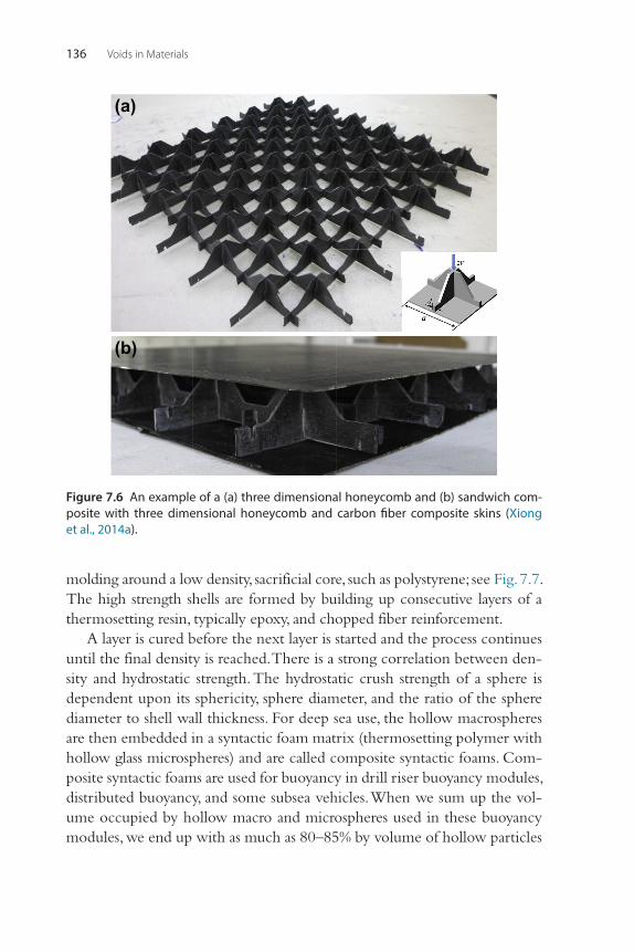
One drawback of honeycomb is the anisotropic behavior stemming from the columnar, closed cell void structure (Xiong et al., 2014b). Attempts to create a three dimensional honeycomb with interconnected porosity have been made to address these shortcomings and add additional function-ality (Xiong et al., 2014a; Xiong et al., 2014b). Xiong et al. found that more complex stresses can be accommodated by pyramidal and “egg” or three dimensional geometries, see Fig. 7.6.
7.2.2 Hollow Composite Macrospheres and Composite Syntactic Foams
Hollow spheres represent another material type used in very high volumes in the deep sea buoyancy applications. Typically, diameters of these hollow spheres range from 3 to 50 mm. These spheres are made via rotational
Figure 7.5 The Airbus A380-800 utilizes many composite materials. The portions high-lighted indicate the components made from sandwich panels having a honeycomb core.
Voids in Materials136
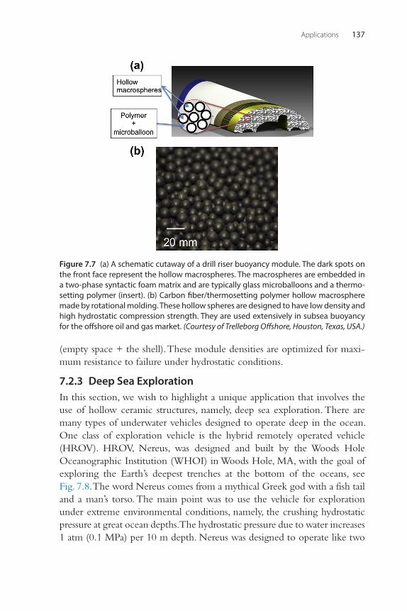
molding around a low density, sacrificial core, such as polystyrene; see Fig. 7.7. The high strength shells are formed by building up consecutive layers of a thermosetting resin, typically epoxy, and chopped fiber reinforcement.
A layer is cured before the next layer is started and the process continues until the final density is reached. There is a strong correlation between den-sity and hydrostatic strength. The hydrostatic crush strength of a sphere is dependent upon its sphericity, sphere diameter, and the ratio of the sphere diameter to shell wall thickness. For deep sea use, the hollow macrospheres are then embedded in a syntactic foam matrix (thermosetting polymer with hollow glass microspheres) and are called composite syntactic foams. Com-posite syntactic foams are used for buoyancy in drill riser buoyancy modules, distributed buoyancy, and some subsea vehicles. When we sum up the vol-ume occupied by hollow macro and microspheres used in these buoyancy modules, we end up with as much as 80–85% by volume of hollow particles
(a)
(b)
Figure 7.6 An example of a (a) three dimensional honeycomb and (b) sandwich com-posite with three dimensional honeycomb and carbon fiber composite skins (Xiong et al., 2014a).
Applications 137
(empty space + the shell). These module densities are optimized for maxi-mum resistance to failure under hydrostatic conditions.
7.2.3 Deep Sea ExplorationIn this section, we wish to highlight a unique application that involves the use of hollow ceramic structures, namely, deep sea exploration. There are many types of underwater vehicles designed to operate deep in the ocean. One class of exploration vehicle is the hybrid remotely operated vehicle (HROV). HROV, Nereus, was designed and built by the Woods Hole Oceanographic Institution (WHOI) in Woods Hole, MA, with the goal of exploring the Earth’s deepest trenches at the bottom of the oceans, see Fig. 7.8. The word Nereus comes from a mythical Greek god with a fish tail and a man’s torso. The main point was to use the vehicle for exploration under extreme environmental conditions, namely, the crushing hydrostatic pressure at great ocean depths. The hydrostatic pressure due to water increases 1 atm (0.1 MPa) per 10 m depth. Nereus was designed to operate like two
Figure 7.7 (a) A schematic cutaway of a drill riser buoyancy module. The dark spots on the front face represent the hollow macrospheres. The macrospheres are embedded in a two-phase syntactic foam matrix and are typically glass microballoons and a thermo-setting polymer (insert). (b) Carbon fiber/thermosetting polymer hollow macrosphere made by rotational molding. These hollow spheres are designed to have low density and high hydrostatic compression strength. They are used extensively in subsea buoyancy for the offshore oil and gas market. (Courtesy of Trelleborg Offshore, Houston, Texas, USA.)
Voids in Materials138
types of vehicles, hence the word “hybrid.” The first mode was to move and explore without any operator input, as an autonomous underwater vehicle (AUV). The second mode of operation was tethered to a surface ship and being controlled by a person not inside of the vehicle, i.e., as an ROV. The tether supplies power and has wires that carry the signals to control Nereus’s movement and instrumentation.
We discussed the processing of the ceramic buoyancy spheres used on Nereus in Section 5.2.5. What follows is a brief description of the condi-tions under which Nereus worked, the design tradeoffs pertaining to voids spaces, and an implosion that occurred on May 9, 2014 about 10 km below the surface, according to the expedition leader Casey Machado (2014).
Nereus was capable of operating in the deepest regions of earth’s oceans known as the hadal zone (down to 11 km). The greatest challenge, of course, at these depths is the large hydrostatic pressure from the seawater. At 11 km, the hydrostatic pressure is around 116 MPa (1140 atm). Compare this to the pressure at sea level of only 0.101 MPa (1 atm), which is the pressure most
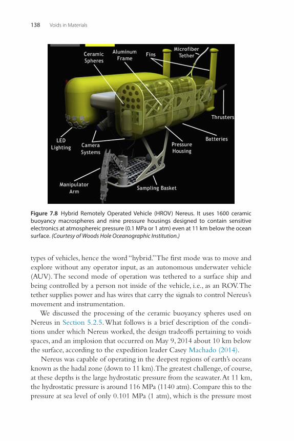
Figure 7.8 Hybrid Remotely Operated Vehicle (HROV) Nereus. It uses 1600 ceramic buoyancy macrospheres and nine pressure housings designed to contain sensitive electronics at atmosphereic pressure (0.1 MPa or 1 atm) even at 11 km below the ocean surface. (Courtesy of Woods Hole Oceanographic Institution.)
Applications 139
systems on earth are required to function in. Any component on Nereus must either be strong enough to withstand the immense hydrostatic pressure, or be inside a protective enclosure (pressure vessel/housing) at 0.101 MPa. Nereus had nine ceramic pressure housings, which protected its electronics and batteries, all of which had the potential to implode. In addi-tion to the pressure housings for electronics, Nereus also used hollow ceramic macrospheres (10 cm in diameter) for buoyancy. There are typically approximately 1600 of these spheres aboard Nereus.
The design challenge is to make strong housings that are also light weight (a priority while trying to provide enough flotation). This led to the use of ceramic materials in place of housings made entirely of titanium. Ceramic materials are low weight and very strong in compres-sion. As we all know, ceramics are very brittle, i.e., susceptible to cata-strophic failure.
According to Machado (2014), while exploring the Kermadec Trench on May 9, 2014, there occurred an implosion. While the system could toler-ate the loss of certain individual pressure housings, the energy released dur-ing an implosion generates a pressure wave that most likely proved too much for other nearby housings to withstand, leading to sympathetic addi-tional implosions. According to him, a risk/probability analysis was con-ducted after the incident, which showed that the pressure housing containing a camera which includes a glass viewport was one of the most likely culprits.
7.3 MICROMETER SCALE VOIDS7.3.1 FoamsThe most widespread use of micrometer scale voids is in traditional stochas-tic foams. These include ceramic, metal, polymer, and composite-based foams. These foams have engineered porosity, which leads to an immediate reduction in density. This reduction in density leads to a change in other properties such as dielectric, mechanical, thermal, and acoustic. Applications stemming from these properties are numerous and diverse: from simply fill-ing spaces, seat and furniture cushions, buoyancy products, proppants to aid in oil and gas recovery, composite cores, thermal insulation, sound and vibration damping, and impact and blast mitigation.
Micrometer scale voids can be found in other applications that are not so obvious as the traditional applications of foams. These include the use of glass microballoons (reinforced voids) to sensitize chemical explosives,
![Some basic theorems in elastostatics of micropolar materials with voids · 2017. 2. 10. · The origin of the theories of bodies with voids goes back to Goodman and Cowin [1]. The](https://img.pdfslide.us/doc/110x75/61454ac634130627ed50e254/some-basic-theorems-in-elastostatics-of-micropolar-materials-with-voids-2017-2.jpg)