Embed Size (px)
Citation preview

Appendix D Scenario Outline Form ES-D-1
Facility: Voatle Scenario No.: 3 Op-Test No.: 2012-301
Examiners:
___________________________
Operators:
Initial Conditions: The plant is at 100% power, MOL, steady state operations.(Base IC # 14, snapped to IC # 183 for HL17 NRC Exam)
Eguiment OOS: Safety Injection Pump “A” is tagged out for motor repair.
Turnover: Maintain 100% power. Containment mini-purge is in service for a Containment entry on thenext shift.
Preloaded Malfunctions:
TU1OB Main Turbine EHC Pump B Auto Start Failure
Overrides
HS-3009 OPEN (Panel Map B-Left, HS-3009 LP-1 MS SPLY to AFW TD PMP-1 to OPEN)
Event Maif. Event EventNo. No. Type* Description
Ti SGO2D I-UO SG # 4 NR LT fails high (LT-554).@ 100% I-SS
TS-SS LCO 3.3.1 Condition ALCO 3.3.1 Condition A, FU 13 Condition ELCO 3.3.2 Condition ALCO 3.3.2 Condition A, FU 5c Condition ILCO 3.3.2 FU 6b Condition D
T2 CVO8 C-OATC CVCS Letdown Leak ORG (Aux. Building — Isolable).@ 25% C-SS
TS-SS
3 NI A N-OATC Places Excess Letdown in service.N-SS
T4 PRO2A l-OATC Controlling PRZR Pressure channel PT-455 fails high.@ 100%. I-SS
TS-SS LCO 3.3.1 Condition A, FU 6 Condition E, LCO 3.3.1 FU 8aCondition M, LCO 3.3.1 FU 8b Condition E,LCO 3.3.2 Condition A, FU id Condition D,LCO 3.3.2 FU 8b Condition L (One hour action),LCO 3.4.1 .a Condition A
T5 TU1 1 C-UO Main Turbine EHC Pump A trips with failure of standby EHC pump toC-SS automatically start.
1
Appendix 0 Scenario Outline Form ES-D-1
Event MaIf. Event EventNo. No. Type* Description
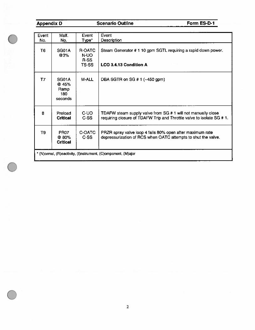
T6 SGO1A R-OATC Steam Generator # 1 10 gpm SGTL requiring a rapid down power.@3% N-UO
R-SSTS-SS LCO 3.4.13 Condition A
T7 SG01A M-ALL DBA SGTR on SG # 1 (-.450 gpm)@45%Ramp
180seconds
8 Preload C-UO TDAFW steam supply valve from SG # 1 will not manually closeCritical C-SS requiring closure of TDAFW Trip and Throttle valve to isolate SG # 1.
T9 PRO7 C-OATC PRZR spray valve loop 4 fails 80% open after maximum rate@ 80% C-SS depressurization of RCS when OATC attempts to shut the valve.Critical
(N)ormal, (R)eactivity, (l)nstrument, (C)omponent, (M)ajor
2

Appendix D Scenario Outline Form ES-D-1
Event 1:
SG # 4 NR LT controlling channel fails high causing MFRV loop # 4 to throttle closed.
Verifiable Actions:
UO — Performs IOA and takes manual control of SG # 4 FW control valves to restore NR levelbetween 60-70%.
Technical Specifications:
LCO 3.3.1 Reactor Trip System (RTS) Instrumentation Condition A
LCO 3.3.1 Reactor Trip System (RTS) Instrumentation FU 13 Condition E
LCO 3.3.2 Engineered Safety Feature Actuation System (ESFAS) Instrumentation Condition A
LCO 3.3.2 Engineered Safety Feature Actuation System (ESFAS) Instrumentation EU 5cCondition I
LCO 3.3.2 Engineered Safety Feature Actuation System (ESEAS) Instrumentation EU 6bCondition D
Event 2:
CVCS Letdown line breaks in the Auxiliary Building that will be isolated lifting letdown relief to thePRT.
Verifiable Actions:
UO — Manipulates penetration room temperature switches at QPCP to determine a leak exists.
OATC — Closes Letdown Orifices HV-8149A, B, C and Letdown Isolations LV-459 and LV-460 toisolate an RCS leak to the PRT.
OATC — Adjusts HC-182 and FIC-121 to establish 8 to 13 gpm seal injection flow with chargingflow approximately 10 gpm greater than total seal injection flow.
Technical Specifications:
LCO 3.4.13 RCS Operational Leakage Condition A (Note: Leakage is isolated after OATC closesthe Letdown Orifices and Isolations)
Event 3:
Excess Letdown will be placed in service to the seal return header to control PRZR level.
Verifiable Actions:
OATC — Sets 1 HC-1 23 to closed. (0% demand).
OATC — Opens Excess Letdown Isolation valves 1-H V-81 53 / 1-H V-81 54.
OATC — Adjusts 1 HC-123 to establish maximum allowable Excess Letdown flow (—30 gpm).
OATC — Adjusts 1 FIC-1 21 and 1 HC-1 82 to control charging and seal injection flows.
3

Appendix D Scenario Outline Form ES-D-1
Event 4:
Controlling PRZR Pressure channel PT-455 fails high resulting in PORV 455A opening and bothPRZR sprays fully open, RCS pressure will be lowering rapidly.
Verifiable Actions:
OATC — Perform lOAs of 18001-C by closing PRZR sprays, closing PORV 455A, and operatingheaters as necessary to control PRZR pressure.
OATC — Manually closes PORV Block Valve 1 HV-8000A to stop LOCA to PRT.
OATC — Controls PRZR heaters and sprays to control PRZR pressure.
OATC — Sets PRZR Master Controller to 25% demand.
OATC — Selects channel 457 I 456 on PRZR Pressure control switch PS-455F.
OATC — Places PRZR heaters and PORV 455A in AUTO and ensures proper operation.
OATC — Places PRZR Pressure Master Controller in AUTO and verifies proper operation.
OATC — Selects channel PT-457 as controlling channel on pressure recorder PS-455G.
Technical Specifications:
LCO 3.3.1 Reactor Trip System (RTS) Instrumentation Condition A
LCO 3.3.1 Reactor Trip System (RTS) Instrumentation EU 6, Condition E
LCO 3.3.1 Reactor Trip System (RTS) Instrumentation EU 8a, Condition M
LCO 3.3.1 Reactor Trip System (RTS) Instrumentation FU 8b, Condition E
LCO 3.3.2 Engineered Safety Features Actuation System (ESFAS) Condition A
LCO 3.3.2 Engineered Safety Features Actuation System (ESFAS) EU id, Condition D
LCO 3.3.2 Engineered Safety Features Actuation System (ESFAS) FU 8b Condition L (one hour)
LCO 3.4.1 .a RCS Pressure, Temperature, and Flow Departure from Nucleate Boiling (DNB)Limits
4

Appendix D Scenario Outline Form ES-D-1
Event 5:
Main Turbine EHC Pump A trips with failure of the standby pump to automatically start.
Verifiable Actions:
UO — Starts EHC pump B prior to Main Turbine / Reactor trip on low EHC pressure of 1100 psig.This will prevent an unnecessary Turbine I Reactor trip and transient on the plant.
Technical Specifications:
None
Event 6:
A 10 gpm SGTL will occur on SG # 1 requiring a rapid down power per 18013-C, this is topreclude the tube leak from propagating into a SGTR per the EPRI Guidelines.
Verifiable Actions:
OATC — Borates as necessary for rapid down power to maintain Tavg — Tref matched.
UO — Reduces Turbine load at < 5% per minute to maintain Tavg — Tref matched.
Event 7, 8:
A DBA SGTR will occur on SG # 1 requiring a plant trip and safety injection.
Verifiable Actions:
OATC — Manually trips the reactor using either QMCB hand switch, manually actuates safetyinjection, and adjusts seal injection to RCPs between 8 to 13 gpm after the SI.
UO — Places SGBD hand switches in hard closed to prevent water hammer to SGBD system.
UO — Throttles AFW flow to maintain SG levels 10— 65%.The UD may perform an early operatoraction and isolate AFW flow to SG # 1 once SG # 1 level is> 10% NR with SS permission.
UO — Isolates ruptured SG # 1 by performing the following.
• Adjusts SG # 1 ARV potentiometer set point to 7.73 (to control at 1160 psig).• Trips the TDAFW pump by closing PV-15129 (Trip and Throttle Valve)• Closes SG # 1 MSIV and Bypass valves.• Isolates FW flow to SG # 1 (MFIV, MFRV, BFIV, BFRV, TDAFW, MDAFW valves all shut)
UO — Blocks Low Steam line Pressure SI and SLI when RCS pressure <2000 psig (P-il) andthen places the steam dumps in Steam Pressure Mode and opens the 3 cool down steam dumpsfor a maximum rate Cooldown.
UO — Closes the steam dumps after selected CETC is reached and controls CETC below thistemperature (usually this is 51 8°F or 506°F depending on ruptured SG pressure).
OATC — Depressurizes RCS with maximum PRZR spray flow to refill the pressurizer.
5

Appendix 0 Scenario Outline Form ES-D-1
Event 9:
OATC — Trips RCP # 4 when a PRZR spray valve will not shut, trips RCP # 1 if necessary.
The scenario may be stopped after this point with chief examiner approval.
CRITICAL TASKS:
1) Isolates SG # ito limit secondary contamination and potential release environment byperforming the following actions no later than the 19030-C procedure steps. These aresteps 6 through ii of 19030-C.
• Adjusts SG # 1 ARV potentiometer set point to 7.73 (to control at 1160 psig).• Trips the TDAFW pump by closing PV-i 5129 (Trip and Throttle Valve)• Closes SG # 1 MSIV and Bypass valves.• Isolates FW flow to SG #1 (MFIV, MFRV, BFIV, BFRV, TDAFW, MDAFW, and SGBD
and Sample valves all shut)
2) Depressurizes PRZR to refill the PRZR with ECCS injection and to limit break flow usingnormal PRZR spray to meet conditions of step 37 of 19030-C.
3) Stops RCP # 4 when PRZR spray valve will not fully close. (Stops RCP # 1 if necessary)This prevents a loss of RCS pressure control requiring a transition to the SGTR ECAseries of EOPs. Also, an uncontrolled backfill of the SG from the secondary side mayoccur resulting in possible loss of shutdown margin and contaminants being introducedinto the primary side. This action is performed per step 38a RNO of 19030-C.
6

‘:‘i NUCLEAR SAFETY FOCUSzJ TARGET ZEROd*j.
Protected Train: EOOS: Green
Alpha LI Yellow
LI Bravo LI Orange
LiRed
Plant 100 % power MOL.Conditions:
Major Activities: Maintain power operations per UOP 1 2004-C section 4.3 forpower operation.
Active LCOs: LI LCO 3.5.2 Condition A is in effect due to SIP A tagged out.
OOS/ Degraded LI NoneCR Instruments:
Narrative LI Containment mini-purge is in service for a plannedStatus: Containment Entry on next shift.
LI SIP A is tagged out for motor repair, expected return toservice time is 24 hours with 48 hours left on a shutdownLCO of 72 hours.
LI The remnants of Hurricane Maya are passing through,severe weather and thunderstorms will be in the area for thenext 8 hours. The Severe Weather Checklist is in effect.

Appendix D Required Operator Actions Form ES-D-2
Op-Test No.: 201 2-301 Scenario No.: 3
Event No.: 1
Event Description: SG # 4 controlling level channel LT-554 fails HIGH requiring UO to takemanual control of SG # 4 MFRV to control SG levels, selects an unaffected level channel, andreturns SG # 4 MFRV to Auto.
Time Position Applicant’s Action or Behavior
UO Diagnose the failure of SG # 4 controlling level channel LT-554.
Symptoms I alarms:
. ALB13-D06 STM GEN 4 HI / LO LVL DEVIATION
. ALB14-D01 STM GEN 4 HI-HI LEVEL ALERT.
Indications:
. MFRV # 4 throttling shut
. Feed flow < steam flow on SG # 4
IMMEDIATE OPERATOR ACTIONS
SS / UO El. Check Steam and feed flows — MATCHED ON ALL SGS.
RNO
El. Take manual control of affected SG feed flow valves to restore NRlevel between 60% and 70%.
[ SG 4 MFRV l-FIC-540 placed in manual and depresses UP arrow toraise FW flow]
SS Enters AOP-1800l-C, Section E for Failure of SG Level Instrumentation.
SUBSEQUENT OPERATOR ACTIONS
SS / UO E2. Selects unaffected SG level channel for control. (Selects 1 LT-549,Ch II on 1 LS-549C)
UO E3. Return SG feed flow valves control to automatic.
[ SG # 4 MFRV 1 -FIC-540 returned to auto]
Cue to Simbooth: IF asked, the Shift Manager has given permission to placethe MFRV in auto.
1

Appendix D Required Operator Actions Form ES-D-2
Op-Test No.: 2012-301 Scenario No.: 3
Event No.: 1
Event Description: SG # 4 controlling level channel LT-554 fails HIGH requiring UO to takemanual control of SG # 4 MFRV to control SG levels, selects an unaffected level channel, andreturns SG # 4 MFRV to Auto.
Time Position Applicant’s Action or Behavior
OATC / UO E4. Initiate the Continuous Actions Page.
UO *E5. Check SG level control maintains NR level — AT 65%.
SS E6 Notify I & C to initiate repairs.
Contacts SSS to perform the following:
. Notify I&C to initiate repairs
. Write a Condition Report
. Notify OPS Duty Manager of AOP entry
SS E7. Bypass the affected channel per 13509-C, Bypass TestInstrumentation (BTI) Panel Operation.
NOTE: It is not expected the SS will desire to bypass the channeL
55 E8. Trip affected channel bistable and place associated MASTERTEST switch in TEST position per TABLE El within 72 hours. (TS3.3.1 & 3.3.2)
NOTE: It is not expected the SS will trip bistables at this time.
SS E9. Initiate the applicable actions of:
. TS3.3.1
. TS 3.3.2
LCO 3.3.1 FU 13 CONDITION E SG LO-LO LEVEL RX TRIP
CONDITION REQUIRED ACTION COMPLETION TIME
A. One or more A.1 Enter the Condition referenced in ImmediatelyFunctions with Table 3.3.1-1 for the channel(s).one or morechannelsinoperable.
2

Appendix D Required Operator Actions Form ES-D-2
Op-Test No.: 201 2-301
Event No.: 1
Scenario No.: 3
Event Description: SG # 4 controlling level channel LT-554 fails HIGH requiring UO to takemanual control of SG # 4 MFRV to control SG levels, selects an unaffected level channel, andreturns SG # 4 MFRV to Auto.
E9. cont.
LCO 3.3.2 FU 6b CONDITION D SG LO-LO LEVEL AEW ACTUATION
CONDITION REQUIRED ACTION COMPLETION TIME
D. One channel D.1 Place channel in trip. 72 hoursinoperable OR
D.2.1 Be in MODE 3 78 hours
AND
D2.2 Be in MODE 4 84 hours
LCO 3.3.2 EU 5c CONDITION I P-14, FWI
E. One channelinoperable
E.1 Place channel in trip.
OR
E.2 Be in MODE 3.
72 hours
78 hours
CONDITION
I. One channelinoperable
REQUIRED ACTION
1.1 Place channel in trip.
OR
SS
1.2 Be in MODE 3
COMPLETION TIME
72 hours
RNO
*Elo Check repairs and surveillances — COMPLETE.
78 hours
*El 0 Perform the following:
a. WHEN repairs and surveillances are complete THENperform Step El 1.
b. Return to procedure and step in effect.
END OF EVENT 1
3

Appendix 0 Required Operator Actions Form ES-D-2
Op-Test No.: 2012-301 Scenario No.: 3
Event No.: 2
Event Description: CVCS Letdown line break ORC that auto isolates the HELBA
valves but requires OATC actions to isolate a Letdown leak to the PRT via relief.
Time Position Applicant’s Action or Behavior
OATC Diagnose Letdown line break CRC and CVCS relief lifting to PAT:UO
Symptoms / alarms:
ALB63-EOl CVCS PIPE BREAK RM PACT ACTUATION
ALB61 -C06 LVL A LEAK DETECTED (short time delay)
ALBO7-C05 LP LTDN HX HI TEMP (short time delay)
ALBO6-F01 CSFST TROUBLE (short time delay)
Indications:
. Both temperature indicators for room RA09 reading high.• Letdown flow lowering toO in 1LI-132C and iLl-i 32A.
Enters AOP 1 8007-C, Section A, TOTAL LOSS OF LETDOWNFLOW.
OATC Al. Isolate letdown relief flowpath by performing the following:
a. Close letdown orifice isolation valves:
. HV-8149A
. HV-8149B
. HV-81 49C
b. Close letdown isolation valves:
. LV-459
. LV-460
4

Appendix 0 Required Operator Actions Form ES-D-2
Op-Test No.: 2012-301 Scenario No.: 3
Event No.: 2
Event Description: CVCS Letdown line break ORC that auto isolates the HELBA
valves but requires OATC actions to isolate a Letdown leak to the PRT via relief.
Time Position Applicant’s Action or Behavior 1OATC A2. Adjust HC-182 and FIC-121 as necessary to establish the
following:
. Seal injection flow to all RCP5 — 8 to 13 GPM.
-AND
. Charging flow - APPROXMATELY 10 GPM GREATERTHAN TOTAL SEAL INJECTION FLOW.
OATC A3. Check pipe break protection valves — OPEN.
. HV-15214(NO)
. HV-8160(NO)
RNO
A3. Perform the following:UO
a. Check affected unit room temperatures.
UNIT 1
. R-A07
. R-A08
. R-A09 (high room temperature for both trains)
b. IF affected room temperatures are greater than 135°F,THEN investigate reason for high temperature in roomsbefore opening affected valves and restoring letdown.
5
Appendix D Required Operator Actions Form ES-D-2
Op-Test No.: 2012-301 Scenario No.: 3
Event No.: 2
Event Description: CVCS Letdown line break ORC that auto isolates the HELBA
valves but requires OATC actions to isolate a Letdown leak to the PRT via relief.
[_TimePosition_[ Applicant’s Action or Behavior
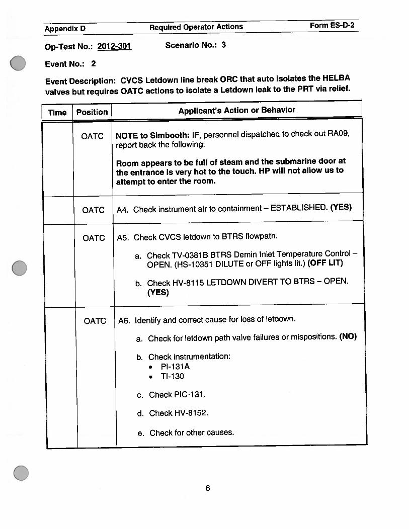
OATC NOTE to Simbooth: IF, personnel dispatched to check out RAO9,
report back the following:
Room appears to be full of steam and the submarine door at
the entrance is very hot to the touch. HP will not allow us to
attempt to enter the room.
OATC A4. Check instrument air to containment — ESTABLISHED. (YES)
OATC A5. Check CVCS letdown to BTRS flowpath.
a. Check TV-0381 B BTRS Demin Inlet Temperature Control —
OPEN. (HS-10351 DILUTE or OFF lights lit.) (OFF LIT)
b. Check HV-81 15 LETDOWN DIVERT TO BTRS - OPEN.
(YES)
OATC A6. Identify and correct cause for loss of letdown.
a. Check for letdown path valve failures or mispositions. (NO)
b. Check instrumentation:. Pl-131A. TI-130
c. Check PIC-131.
d. Check HV-8152.
e. Check for other causes.
6

Appendix D Required Operator Actions Form ES-D-2
Op-Test No.: 2012-301 Scenario No.: 3
Event No.: 2
Event Description: CVCS Letdown line break ORC that auto isolates the HELBAvalves but requires OATC actions to isolate a Letdown leak to the PRT via relief.
Time_]_Position_[ Applicant’s Action or Behavior
OATC A7. Check normal letdown — AVAILABLE. (NO)
RNO
A7. Perform the following:
a. Establish Excess Letdown by initiating 13008, CHEMICALAND VOLUME CONTROL SYSTEM EXCESS LETDOWN.
Note to examiner: SS should wait here for Excess Letdown to beplaced in service prior to proceeding to step A9.
Note to examiner: Excess Letdown steps are on page # 10.
GO TO EVENT 3 for placing Excess Letdown in service steps, thenreturn to step A9 once Excess Letdown has been placed in service.
b. GotoStepA9.
7

Appendix D Required Operator Actions Form ES-D-2
Op-Test No.: 2012-301 Scenario No.: 3
Event No.: 2
Event Description: CVCS Letdown line break ORC that auto isolates the HELBA
valves but requires OATC actions to isolate a Letdown leak to the PRT via relief.
Time Position_[ Applicant’s Action or Behavior
OATC A9. Initiate the Continuous Actions Page.uO
OATC AlO. Verify PRZR level - TRENDING TO PROGRAM. (YES)
Note to examiner: The OATC should be able to turn PRZR level to
a down trend with Excess Letdown in service.
8

Appendix D Required Operator Actions Form ES-D-2
Op-Test No.: 2012-301 Scenario No.: 3
Event No.: 2
Event Description: CVCS Letdown line break ORC that auto isolates the HELBAvalves but requires OATC actions to isolate a Letdown leak to the PRT via relief.
Time Position Applicant’s Action or Behavior
SS All. Check normal letdown flow — ESTABLISHED. (NO)
RNO
Al 1. Perform the following:
a. WHEN normal letdown capability is restored,THEN restore normal letdown by initiating 13006,CHEMICAL AND VOLUME CONTROL SYSTEM.
b. Evaluate the impact of continued power operation withnormal letdown out of service.
c. WHEN Normal Letdown restored remove Excess Letdownby initiating 13008, CHEMICAL VOLUME CONTROLSYSTEM EXCESS LETDOWN.
OATC A12. Return to procedure and step in effect.
END OF EVENT 2, proceed to EVENT 4.
9

Appendix D Required Operator Actions Form ES-D-2
Op-Test No.: 201 2-301 Scenario No.: 3
Event No.: 3
Event Description: The OATC places Excess letdown in service per direction of the SS tomaintain PRZR level after letdown is isolated to stop the RCS leak. The OATC will use SOP13008-1, to place excess letdown in service.
Time Position Applicant’s Action or Behavior
OATC Section 4.1 of 13008-1 is selected.
OATC NOTE: Independent Verifications performed within Section 4.1 aredocumented on Checklist 1.
4.1.1 Verify Reactor power is maintained < 3622.6 MWT while ExcessLetdown is in service and LEFM is in service. IF LEFM is NOT inservice, maintain power 3562 MWT per guidance of 12004-C.
OATC 4.1 .2 Verify that a CVCS Charging Pump is running.
OATC 4.1.3 Verity CLOSED RX HEAD VENT TO EXCESS LETDOWNISOLATION 1 -HV-8098.
OATC 4.1.4 Verify flow controller EXCESS LETDOWN, 1 HO-i 23 is set toclosed (0% demand).
OATC 4.1.5 Verity OPEN RCPs Seal Leakoff Isolation valves:
• 1 -HV-81 00 RCPS SEAL LEAKOFF ORC ISOLATION
. 1-HV-81 12 RCPS SEAL LEAKOFF IRC ISOLATION
10

Appendix D Required Operator Actions Form ES-D-2
Op-Test No.: 201 2-301 Scenario No.: 3
Event No.: 3
Event Description: The OATC places Excess letdown in service per direction of the SS to
maintain PRZR level after letdown is isolated to stop the RCS leak. The OATC will use SOP
13008-1, to place excess letdown in service.
Time Position Applicant’s Action or Behavior
OATC 4.1.6 Verity EXCESS LETDOWN TO VCT, 1HS-8143 is in the OPEN
VCT position.
OATC 4.1.7 Verity Reactor power is maintained 3622.6 MWT while ExcessLetdown is in service and LEFM is in service. IF LEFM is NOT in
service, maintain power 3562 MWT per guidance of 12004-C.
OATC 4.1.8 Open EXCESS LETDOWN LINE Isolation Valves:
. 1-H V-81 53 EXCESS LETDOWN LINE ISO VLV
. 1-HV-8154 EXCESS LETDOWN LINE ISO VLV
OATC 4.1.9 Record the following:
. Pressure on indicator EXCESS LETDOWN HX OUTLET,lPl-124.
. Temperature on indicator EXCESS LETDOWN HXOUTLET, 1TI-122.
Note to examiner: ALB63-A06 FILTERS BACKFLUSH PNL ALARM
will illuminate shortly after placing Excess Letdown in service.
11
Appendix D Required Operator Actions Form ES-D-2
Op-Test No.: 2012-301 Scenario No.: 3
Event No.: 3
Event Description: The OATC places Excess letdown in service per direction of the SS to
maintain PRZR level after letdown is isolated to stop the RCS leak. The OATC will use SOP
13008-1, to place excess letdown in service.
Time Position Applicant’s Action or Behavior
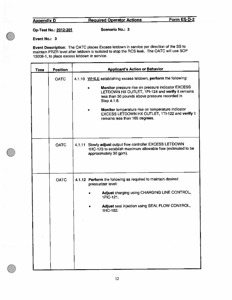
OATC 4.1.10 WHILE establishing excess letdown, perform the following:
. Monitor pressure rise on pressure indicator EXCESSLETDOWN HX OUTLET, 1PI-124 and verify it remainsless than 50 pounds above pressure recorded inStep 4.1.8.
. Monitor temperature rise on temperature indicatorEXCESS LETDOWN HX OUTLET, 1TI-122 and verify itremains less than 165 degrees.
OATC 4.1.11 Slowly adjust output flow controller EXCESS LETDOWN1HC-123 to establish maximum allowable flow (estimated to beapproximately 30 gpm).
OATC 4.1.12 Perform the following as required to maintain desiredpressurizer level:
. Adjust charging using CHARGING LINE CONTROL,1 FIC-121.
. Adjust seal injection using SEAL FLOW CONTROL,1 HC-1 82.
12

Appendix D Required Operator Actions Form ES-D-2
Op-Test No.: 2012-301 Scenario No.: 3
Event No.: 3
Event Description: The OATC places Excess letdown in service per direction of the SS to
maintain PRZR level after letdown is isolated to stop the RCS leak. The OATC will use SOP
13008-1, to place excess letdown in service.
Time Position Applicant’s Action or Behavior
OATC 4.1.13 IF normal letdown is isolated, align the outlet of the Seal Water
Heat Exchanger to the Volume Control Tank spray nozzle asfollows: (IV REQUIRED) (N/A if previously performed)
a. Unlock and open CVCS SEALS SEAL WATER HXOUTLET TO VCT, 1-1208-U6-104. (KEY 10P2-281)(RA-26)
b. Close CVCS SEALS SEAL WATER HX OUTLET TONCP SUCTION, 1-1 208-U6-1 06. (RA-26)
OATC 4.1.14 IF directed by SS to transfer excess letdown to the RCDT,perform the following:
a. Verity RCDT system is aligned to accept ExcessLetdown flow per 13002-1 “Reactor Drain TankOperation.”
b. Place EXCESS LETDOWN TO VCT, 1 HS-81 43 to theOPEN RCDT position.
c. Monitor temperature rise on EXCESS LETDOWN HXOUTLET 1TI-122 and verity it remains less than 165degrees.
d. Slowly raise output on flow controller EXCESSLETDOWN, 1HC-123 to establish maximum allowableflow.
e. swap to RCDT is being performed for Chemistry controlor level control Step 4.2.7.
f. Perform the following as required to maintain desiredpressurizer level:
. Adjust charging using CHARGING LINECONTROL, 1 FIC-121.
. Adjust seal injection using SEAL FLOWCONTROL, 1HC-182.
13
Appendix D Required Operator Actions Form ES-D-2
Op-Test No.: 201 2-301 Scenario No.: 3
Event No.: 3
Event Description: The OATC places Excess letdown in service per direction of the SS tomaintain PRZR level after letdown is isolated to stop the RCS leak. The OATC will use SOP13008-1, to place excess letdown in service.
Time Position Applicant’s Action or Behavior
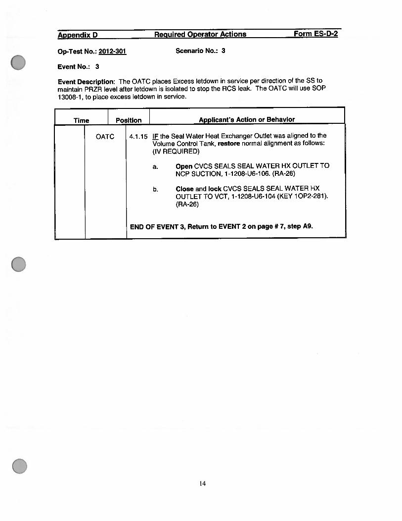
OATC 4.1.15 H the Seal Water Heat Exchanger Outlet was aligned to theVolume Control Tank, restore normal alignment as follows:(IV REQUIRED)
a. Open CVCS SEALS SEAL WATER HX OUTLET TONCP SUCTION, 1-1208-U6-106. (RA-26)
b. Close and lock CVCS SEALS SEAL WATER HXOUTLET TO VCT, 1-1 208-U6-1 04 (KEY 1 OP2-281).(RA-26)
END OF EVENT 3, Return to EVENT 2 on page # 7, step A9.
14

Appendix D Required Operator Actions Form ES-D-2
Op-Test No.: 2012-301 Scenario No.: 3
Event No.: 4
Event Description: PRZR Pressure channel PT-455 fails high resulting in PRZR
PORV 455A and both PRZR Sprays fully opening. The OATC will have to take
manual action to prevent a Reactor trip and SI.
Time Position Applicant’s Action or Behavior
OATC Diagnose the high failure of PRZR Pressure channel PT-455.
Symptoms / alarms:
• ALB11-B03 PRZR HI PRESS. ALB1 1 -COl PRZR CONTROL HI LEVEL DEV AND HEATERS ON
. ALB11-C03 PRZR HI PRESS CHANNEL ALERT
. ALB12-D03 PRZR PRESS LO PORV BLOCK
. ALB12-E04 PV-0455A OPEN SIGNAL
. ALBO6-F06 CSFST TROUBLE
Indications:
. PRZR Pressure channel PT-455 off scale high.
. PRZR Pressure channels PT-456, 457, and 458 rapidly lowering.
. Both PRZR Sprays full open.
OATC AOP 18001-C, Section C IMMEDIATE ACTIONS
Cl. Check RCS pressure - STABLE OR RISING. (NO)
RNO:
Cl. Perform the following:
• Close spray valves.
• Close affected PRZR PORV.
• Operate PRZR heaters as necessary.
SS Enters AOP 18001 -C, Section C and verifies immediate operator
actions properly completed.
15

Appendix D Required Operator Actions Form ES-D-2
Op-Test No.: 2012-301 Scenario No.: 3
Event No.: 4
Event Description: PRZR Pressure channel PT-455 fails high resulting in PRZR
PORV 455A and both PRZR Sprays fully opening. The OATC will have to take
manual action to prevent a Reactor trip and SI.
[ime } Position Applicant’s Action or Behavior
OATC C2. Check controlling channel — OPERATING PROPERLY. (NO)
RNO:
C2. Perform the following:
a. Place HS-455A in close.
b. Place PRZR spray valve controllers in manual.
OATC C3. Initiate the Continuous Actions Page.UO
OATC C4. Control PRZR pressure using heaters sprays —
BETWEEN 2220 AND 2250 PSIG.
OATC C5. Check PIC-455A Pressurizer Master Pressure Controller—INAUTO WITH OUTPUT SIGNAL APPROXIMATELY 25%.(NO)
RNO:
C5. Place PIC-455A in manual and adjust controller output toapproximately 25%.
OATC C6. Check affected channel selected on PS-455F PRZR PRESSCNTL SELECT. (YES)
16
Appendix D Required Operator Actions Form ES-D-2
Op-Test No.: 2012-301 Scenario No.: 3
Event No.: 4
Event Description: PRZR Pressure channel PT-455 fails high resulting in PRZR
PORV 455A and both PRZR Sprays fully opening. The OATC will have to take
manual action to prevent a Reactor trip and SI.
Time [ Position Applicant’s Action or Behavior
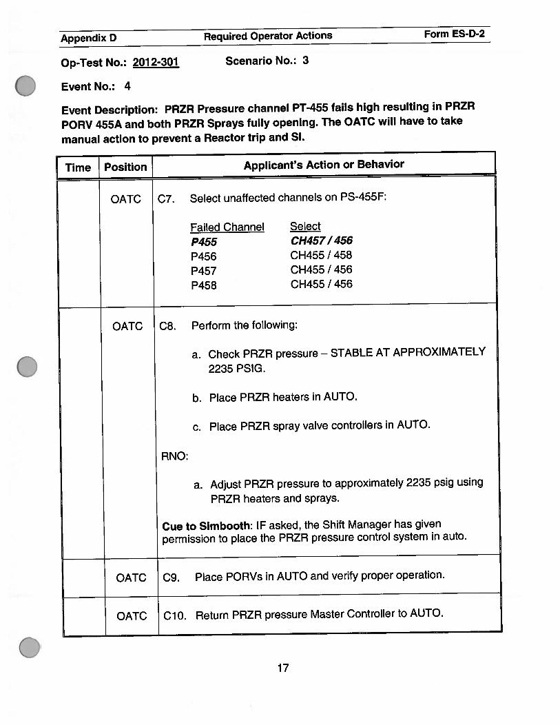
OATC C7. Select unaffected channels on PS—455F:
Failed Channel Select
P455 CH4571456
P456 CH455/458
P457 CH455/456
P458 CH455/456
OATC C8. Perform the following:
a. Check PRZR pressure — STABLE AT APPROXIMATELY
2235 PSIG.
b. Place PRZR heaters in AUTO.
c. Place PRZR spray valve controllers in AUTO.
RNO:
a. Adjust PRZR pressure to approximately 2235 psig using
PRZR heaters and sprays.
Cue to Simbooth: IF asked, the Shift Manager has givenpermission to place the PRZR pressure control system in auto.
OATC C9. Place PORVs in AUTO and verify proper operation.
OATC ClO. Return PRZR pressure Master Controller to AUTO.
17

Appendix D Required Operator Actions Form ES-D-2
Op-Test No.: 2012-301 Scenario No.: 3
Event No.: 4
Event Description: PRZR Pressure channel PT-455 fails high resulting in PRZRPORV 455A and both PRZR Sprays fully opening. The OATC will have to takemanual action to prevent a Reactor trip and SI.
Time Position Applicant’s Action or Behavior ]OATC Cii. Select same channel on PS-455G PRZR PRESS REC SEL
as selected on PS-455F.
457
OATC Ci2. Check P-i i status light on BPLB indicates correctly for plantcondition within one hour.
OFF
OATC C13. Notify l&C to initiate repairs.
SS will call typically call the SSS to perform the following:
. Notify Operations Duty Manager of the AOP entry
. Write a Condition Report
. Notify l&C
OATC C14. Bypass the affected instrument channel using 13509 C,BYPASS TEST INSTRUMENTATION (BTI) PANELOPERATION, if desired.
NOTE: SS is NOT expected to bypass failed channel.
18

Appendix D Required Operator Actions Form ES-D-2
Op-Test No.: 2012-301 Scenario No.: 3
Event No.: 4
Event Description: PRZR Pressure channel PT-455 fails high resulting in PRZR
PORV 455A and both PRZR Sprays fully opening. The OATC will have to take
manual action to prevent a Reactor trip and SI.
Time Position Applicant’s Action or Behavior
SS 015. Trip the affected channel bistables and place the associated
MASTER TEST switches in TEST position per TABLE Cl
within 72 hours. (TS 3.3.1 & 3.3.2)
NOTE: SS expected to leave bistables untripped during allowed
out of service time to facilitate troubleshooting by I&C.
SS C16. Initiate the applicable actions of:
• TS3.3.1 ReactorTrip
Function Condition
LCO3.3.1 A
6OTzXT E
8a Low PRZR pressure M
8b High PRZR pressure E
• TS3.3.2ESFAS
Function Condition
LCO3.3.2 A
id SI low PRZR pressure D
8b P-i 1 Interlock L (one hour action)
• TS 3.4.1 .a DNB
RCS pressure < 2199 psig B (Momentary)
19
Appendix D Required Operator Actions Form ES-D-2
Op-Test No.: 2012-301 Scenario No.: 3
Event No.: 4
Event Description: PRZR Pressure channel PT-455 fails high resulting in PRZR
PORV 455A and both PRZR Sprays fully opening. The OATC will have to take
manual action to prevent a Reactor trip and SI.
Time Position_[ Applicant’s Action or Behavior
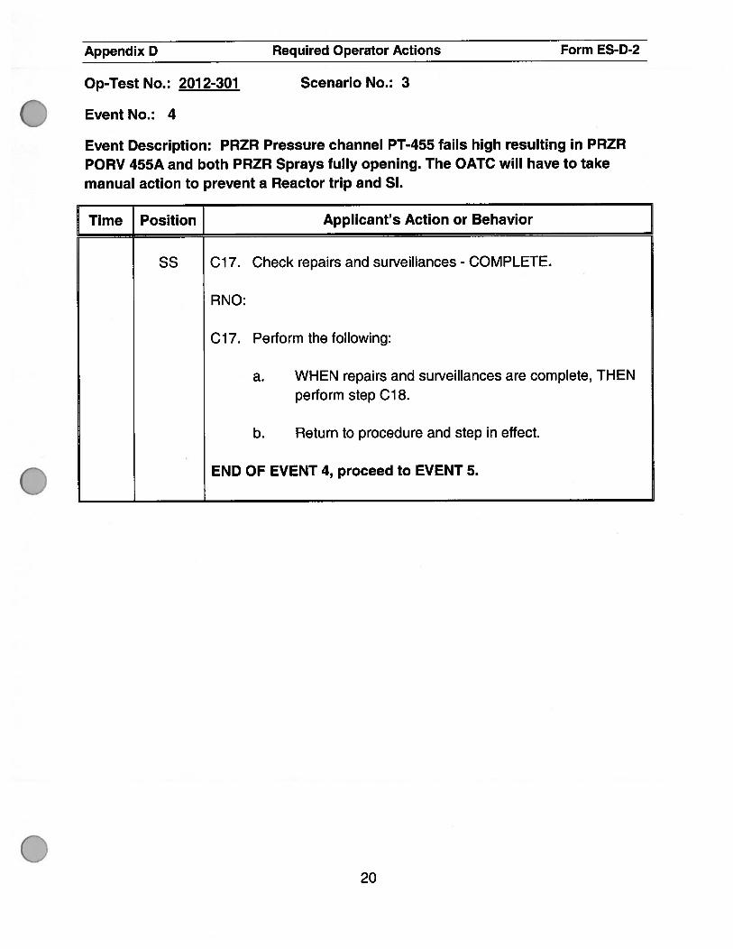
SS C17. Check repairs and surveillances - COMPLETE.
RNO:
C17. Perform the following:
a. WHEN repairs and surveillances are complete, THENperform step C18.
b. Return to procedure and step in effect.
END OF EVENT 4, proceed to EVENT 5.
20

Appendix D Required Operator Actions Form ES-D-2
Op-Test No.: 2012-301 Scenario No.: 3
Event No.: 5
Event Description: Main Turbine EHC pump 1 trips and the standby pump fails to
automatically start on low pressure. The UO will refer to ARP-17033-1 for
corrective actions. The standby pump will be manually started to prevent a
turbine trip on low EHC pressure.
Time Position Applicant’s Action or Behavior
UO Diagnoses trip of EHC pump:
Alarms:ALB33-B07 480V SWGR 1 NB02 TROUBLEALB2O-D05 HYD FLUID LO PRESS (after severalminutes)
Indications:EHC pump 1 (HS-6539):Red—OFFAmber-ONGreen—ONEHC pressure (P1-6338) <1600 psig and lowering.
EHC Pump 1 amps (11-40073) drop to 0 amps.
UO Refers to ARP 17033-1 for Window B07.
(480V SWGR 1 NBO2 TROUBLE)
21

Appendix D Required Operator Actions Form ES-D-2
Op-Test No.: 2012-301 Scenario No.: 3
Event No.: 5
Event Description: Main Turbine EHC pump 1 trips and the standby pump fails to
automatically start on low pressure. The UO will refer to ARP-17033-1 for
corrective actions. The standby pump will be manually started to prevent a
turbine trip on low EHC pressure.
Time Position Applicant’s Action or Behavior
UO ARP 17033-1 WINDOW B07
1.0 PROBABLE CAUSE
1. One of the breakers on Switchgear 1 NBO2 tripped due to
a fault.
2. Bus ground fault.
3. Potential transformer/fuse failure.
4. Loss of bus voltage from Switchgear 1 NAO4.
5. Transformer 1 NBO2X winding high temperature.
6. Loss of 1 25V DC control power from Panel 1 ND21.
7. Loss of power to transformer temperature monitor.
2.0 AUTOMATIC ACTIONS
NONE
22

Appendix D Required Operator Actions Form ES-D-2
Op-Test No.: 2012-301 Scenario No.: 3
Event No.: 5
Event Description: Main Turbine EHC pump 1 trips and the standby pump fails to
automatically start on low pressure. The UO will refer to ARP-17033-1 for
corrective actions. The standby pump will be manually started to prevent a
turbine trip on low EHC pressure.
Time Position Applicant’s Action or Behavior
UO NOTE: Loss of 125V DC control power results in loss of breaker
remote/local remote operating capabilities and associated
control circuit trip features.
3.0 INITIAL OPERATOR ACTIONS
NONE
4.0 SUBSEQUENT OPERATOR ACTIONS
1. Check for associated alarms and indications.
2. Dispatch an operator to Switchgear 1 NBO2 to check for:
a. Ground fault indications.
b. Other abnormal conditions.
3. IF alarm is due to a breaker tripping on fault orundervoltage:
a. Determine affected loads.
b. Start redundant loads, if applicable.
4. IF alarm is due to a loss of 125V DC control power,dispatch an operator to the switchgear to manuallyoperate breakers, under the direction of the ControlRoom.
5. IF a bus ground fault is indicated, selectively shift toredundant loads and de-energize components to locatethe ground.
23

Appendix D Required Operator Actions Form ES-D-2
Op-Test No.: 2012-301 Scenario No.: 3
Event No.: 5
Event Description: Main Turbine EHC pump 1 trips and the standby pump fails toautomatically start on low pressure. The UO will refer to ARP-17033-1 forcorrective actions. The standby pump will be manually started to prevent aturbine trip on low EHC pressure.
Time Position Applicant’s Action or Behavior
uO 40 SUBSEQUENT OPERATOR ACTIONS (continued)
6. Initiate maintenance as required to correct cause of thealarm.
5.0 COMPENSATORY OPERATOR ACTIONS
1. Initiate maintenance to correct problem (i.e., restorealarm).
2. IF after three days the alarm has NOT been restored,initiate a Temporary Modification per 00307-C,“Temporary Modifications” to clear the bad input(s).Record this action required on Figure 5 of 10018-C,“Annunciator Control.”
24

Appendix D Required Operator Actions Form ES-D-2
Op-Test No.: 2012-301 Scenario No.: 3
Event No.: 5
Event Description: Main Turbine EHC pump 1 trips and the standby pump fails to
automatically start on low pressure. The UO will refer to ARP-17033-1 forcorrective actions. The standby pump will be manually started to prevent aturbine trip on low EHC pressure.
Time Position] Applicant’s Action or Behavior
ARP 17020-1 WINDOW D05
1.0 PROBABLE CAUSE
1. Failure of Electrohydraulic Control (EHC) Fluid Pumps.
2. Clogged strainers and filters in pump suction ordischarge.
3. EHC Fluid System leak.
2.0 AUTOMATIC ACTIONS
1. If pressure drops below 1400 psig, the standby EHCFluid Pump will start.
2. If pressure continues to drop to 1100 psig, the Turbinewill trip.
3.0 INITIAL OPERATOR ACTIONS
1. IF a reactor trip occurs, Go To 19000 C, “E 0 ReactorTrip Or Safety Injection.”
2. Verify standby EHC Fluid Pump is on, if needed.
4.0 SUBSEQUENT OPERATOR ACTIONS
CAUTIONEHC fluid is a fire resistant fluid that may be harmful topersonnel. Observe proper safety precautions when incontact with this fluid.
1. Dispatch an operator to the Hydraulic Power Unit tocheck for system leaks or pump failure.
2. IF equipment failure is indicated, initiate maintenanceas required.
25

Appendix D Required Operator Actions Form ES-D-2
Op-Test No.: 2012-301 Scenario No.: 3
Event No.: 5
Event Description: Main Turbine EHC pump 1 trips and the standby pump fails toautomatically start on low pressure. The UO will refer to ARP-17033-1 forcorrective actions. The standby pump will be manually started to prevent aturbine trip on low EHC pressure.
Time Position Applicant’s Action or Behavior
UO NOTE: Student notices green and amber lights for EHC pump 1and then starts EHC pump 2 with SS permission.
NOTE: After starting EHC pump 2 EHC pressure returns to1600 psig.
UO Will call SSS to:SS
. Write condition report
. Notify Maintenance
END OF EVENT 5, proceed to EVENT 6.
26

Appendix D Required Operator Actions Form ES-D-2
Op-Test No.: 201 2-301 Scenario No.: 3
Event No.: 6
Event Description: SG 1 develops a 15 GPM tube leak requiring entry into AOP 18009-C. With
SGTL> 5 gpm a rapid shutdown using AOP 18013-C is required. This event will be used for the
required reactivity manipulation.
Time Position Applicant’s Action or Behavior
CREW Diagnose SG Tube Leakage:
ALARMS:
ALBO5-B03 INTMD RADIATION ALARMALBO5-C03 HIGH RADIATIONRE-0724 — Primary to secondary leakage monitor (IPC)RE-0810 — SJAE low range monitor (IPC)RE-12839C — SJAE monitor (IPC)
INDICATIONS:
Charging flow increases if in auto. (expect manual control)PRZR level slowly lowers.
SS Enters AOP 18009-C, Steam Generator Tube Leak and directs
actions of OATC / UO listed in the following steps. (Crew Update)
OATC / UO 1. Initiate continuous actions page.
OATC 2. Maintains PRZR level by:
a. Adjusting charging flow.
b. Check PRZR level stable or rising.
RNOb.1) Isolating letdown (only necessary if at 120 GPM.letdown)
RNOb.2) Start additional charging pump. (will not be necessary)
RNOb.3) IE PRZR level can NQI be maintained greater than 9%,THEN perform the following:
a. Trip the Reactor.
b. WHEN Reactor trip verified, THEN actuate SI.
c. Go to 19000 C, E 0 REACTOR TRIP OR SAFETYINJECTION.
27
Appendix D Required Operator Actions Form ES-D-2
Op-Test No.: 2012-301 Scenario No.: 3
Event No.: 6
Event Description: SG 1 develops a 15 GPM tube leak requiring entry into AOP 18009-C. With
SGTL> 5 gpm a rapid shutdown using AOP 18013-C is required. This event will be used for the
required reactivity manipulation.
Time Position Applicant’s Action or Behavior
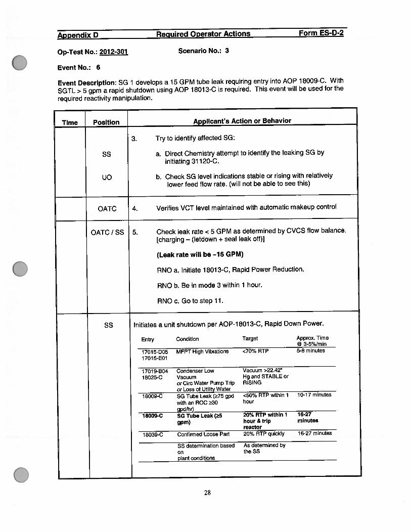
3. Try to identify affected SG:
SS a. Direct Chemistry attempt to identify the leaking SG byinitiating 31 120-C.
UO b. Check SG level indications stable or rising with relativelylower feed flow rate. (will not be able to see this)
OATC 4. Verifies VCT level maintained with automatic makeup control
OATC / SS 5. Check leak rate < 5 GPM as determined by CVCS flow balance.[charging — (letdown + seal leak off)]
(Leak rate will be -15 GPM)
RNO a. Initiate 18013-C, Rapid Power Reduction.
RNO b. Be in mode 3 within 1 hour.
RNOc. Go to step 11.
SS Initiates a unit shutdown per AOP-18013-C, Rapid Down Power.
Entry Condition Target Approx. Time@ 3-5%/rn in
1701 5-D05 MFPT High Vibrations <70% RTP 5-8 minutes
1 7015-E01
1701 9-B04 Condenser Low Vacuum >22.4218025-C Vacuum Hg and STABLE or
orCirc Water Pump Trip RISINGor Loss of utility Water
18009-C SG Tube Leak (75 gpd <50% RTP within 1 10-17 minutes
with an ROC 30 hour
gpd/hr)18009-C SG Tube Leak (5 20% RTP within 1 16-27
gpm) hour & trip minutesreactor
1 8039-C Confirmed Loose Part 20% RTP quickly 16-27 minutes
SS determination based As determined byon theSSplant conditions
28

Appendix D Required Operator Actions Form ES-D-2
Op-Test No.: 2012-301 Scenario No.: 3
Event No.: 6
Event Description: SG 1 develops a 15 GPM tube leak requiring entry into AOP 18009-C. With
SGTL> 5 gpm a rapid shutdown using AOP 18013-C is required. This event will be used for therequired reactivity manipulation.
Time Position Applicant’s Action or Behavior
SS 1. Performs SHUTDOWN BRIEFING
METHOD
• Auto rod control should be used.
• Reduce Turbine Load at approximately 3% RTP per minute(approx 36 MWe) up to 5% RTP (approx 60 MWe).
• Borate considering the calculations from the reactivity briefingsheet and BEACON.
• Maintain AFD within the doghouse.
• SS (or SRO designee) - Maintain supervisory oversight.
• AU rod withdrawals will be approved by the SS.
• Approval for each reactivity manipulation is not necessary as longas manipulations are made within the boundaries established inthis briefing (i.e. turbine load adjustment up to 60 MWe, etc.).
• A crew update should be performed at approximately every 100MWe power change.
• If manpower is available, peer checks should be used for allreactivity changes.
OPERATIONAL LIMITS
• Maintain TAVG within ±6°F of TREE. If TAVG/TREF mismatch>6°F and not trending toward a matched condition if TAVG
551°F, then trip the reactor.
• If load reduction due to a loss of vacuum, every effort should bemade to maintain the steam dumps closed. (Permissive C-9> 24.92° Hg).
INDUSTRY OE
• Shift supervision must maintain effective oversight and exerciseconservative decision making.
• Correction of significant RCS TAVO deviations should only be viasecondary plant control manipulations and primary plantcontrol manipulations. (i.e., do not withdraw control rods or dilute).
29

Appendix D Required Operator Actions Form ES-D-2
Op-Test No.: 2012-301 Scenario No.: 3
Event No.: 6
Event Description: SG 1 develops a 15 GPM tube leak requiring entry into AOP 18009-C. With
SGTL>5 gpm a rapid shutdown using AOP 18013-C is required. This event will be used for the
required reactivity manipulation.
Time Position Applicant’s Action or Behavior
OATC 2. Verify rods in AUTO.
UO 3. Reduce Turbine Load at the desired rate up to 5%/rn in(60 MWE/rnin).
OATC 4. Borate as necessary by initiating 13009, CVCS REACTORMAKEUP CONTROL SYSTEM.
Note to examiner: Boration steps from 13009 start on page # 32.IF, crew Emergency Borates, steps from 13009 start on page # 38.
OATC / UO 5. Initiate the Continuous Actions Page.
OATC / UO 6. Check desired ramp rate - LESS THAN Q EQUAL TO5%/MI N.
OATC 7. Maintain Tavg within 6°F of Tref:
a. Monitor Tavg/Tref deviation (UT-0495).
b. Verify rods inserting as required.
c. Energize Pressurizer back-up heaters as necessary.
OATC / UO 8. Maintain reactor power and turbine power — MATCHED.
a. Balance reactor power with secondary power reduction usingboration and control rods.
b. Check rate of reactor power reduction ADEQUATE FORPLANT CONDITIONS.
c. Check RCS Tavg GREATER THAN 551 °F (TS 3.4.2).
d. Check RCS Tavg - WITHIN 6°F OF TREF.
30
Appendix D Required Operator Actions Form ES-D-2
Op-Test No.: 2012-301 Scenario No.: 3
Event No.: 6
Event Description: SG 1 develops a 15 GPM tube leak requiring entry into AOP 18009-C. WithSGTL> 5 gpm a rapid shutdown using AOP 18013-C is required. This event will be used for therequired reactivity manipulation.
Time Position Applicant’s Action or Behavior
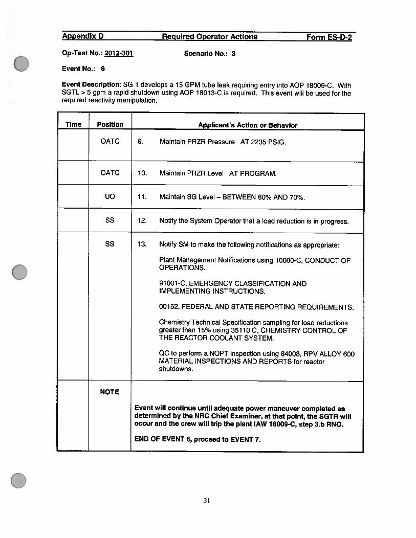
OATC 9. Maintain PRZR Pressure AT 2235 PSIG.
OATC 10. Maintain PRZR Level AT PROGRAM.
UO 11. Maintain SG Level — BETWEEN 60% AND 70%.
SS 12. Notify the System Operator that a load reduction is in progress.
SS 13. Notify SM to make the following notifications as appropriate:
Plant Management Notifications using 10000-C, CONDUCT OFOPERATIONS.
91001-C, EMERGENCY CLASSIFICATION ANDIMPLEMENTING INSTRUCTIONS.
00152, FEDERAL AND STATE REPORTING REQUIREMENTS.
Chemistry Technical Specification sampling for load reductionsgreater than 15% using 35110 C, CHEMISTRY CONTROL OFTHE REACTOR COOLANT SYSTEM.
QC to perform a NOPT inspection using 84008, RPV ALLOY 600MATERIAL INSPECTIONS AND REPORTS for reactorshutdowns.
NOTE
Event will continue until adequate power maneuver completed asdetermined by the NRC Chief Examiner, at that point, the SGTR willoccur and the crew will trip the plant lAW 18009-C, step 3.b RNO.
END OF EVENT 6, proceed to EVENT 7.
31

Appendix D Required Operator Actions Form ES-D-2
Op-Test No.: 2012-301 Scenario No.: 3
Event No.: 6 Rapid Power Reduction boration steps
Event Description: Rapid Power Reduction boration steps from 13009.
Time Position Applicant’s Action or Behavior
OATC 4.2 BORATION
4.2.1 Determine the existing RCS boron concentration from BoronMeter 1-Al-40134 OR by sample analysis.
4.2.2 To determine the number of gallons of boric acid required toborate the RCS, perform the following.
IF borating to required boron for a xenon free cool down,obtain the maximum boron concentration for the cool downrange from the PTDB Tab 1.3.4-Ti and T2.
OR
IF borating to a desired boron concentration, determine thedesired change in boron concentration by subtracting theexisting concentration from the desired concentration.
THEN
Determine the amount of boric acid necessary to accomplishthe desired change in boron concentration using PTDBTab 2.3 and correct the obtained value using PTDB Tab 2.1.
Note to examiner: The OATC may also use a Beacon Bookcalculation to obtain a boron addition target for the Rapid PowerReduction. For a power reduction to 70%, this will be a boronaddition of 230 gallons at 30 gpm.
OATC 4.2.3 Place VCT MAKEUP CONTROL 1 -HS-40001 B in STOP.
OATC 4.2.4 Place VCT MAKEUP MODE SELECT i-HS-40001A in BOR.
32

Appendix D Required Operator Actions Form ES-D-2
Op-Test No.: 2012-301 Scenario No.: 3
Event No.: 6 Rapid Power Reduction boration steps
Event Description: Rapid Power Reduction boration steps from 13009.
[[, Time Position Applicant’s Action or Behavior
NOTE
If necessary, boric acid flow may be adjusted using 1 -FIC-Ol 10 withSS concurrence. Changes to pot setting should be logged in theControl Room Log and restored at completion of activity.
OATC 4.2.5 Adjust potentiometer on Boric Acid Blender Flow Controller1 -FIC-Ol 10 as desired and verify in AUTO.
CAUTION
Digital counter setting on BORIC ACID TO BLENDER integrator1-FQI-01 10 reads in tenth-gallon increments.
OATC 4.2.6 Set BORIC ACID TO BLENDER integrator 1 -FQI-01 10 to thedesired amount of Boric Acid.
33

Appendix D Required Operator Actions Form ES-D-2
Op-Test No.: 2012-301 Scenario No.: 3
Event No.: 6 Rapid Power Reduction boration steps
Event Description: Rapid Power Reduction boration steps from 13009.
Time Position Applicant’s Action or Behavior
OATC 4.2.7 Verify the following:
. BA TO BLENDER 1 -HS-O1 1 OA is in AUTO.
. BLENDER OUTLET TO CHARGING PUMPS SUCT1 -HS-01 1 OB is in AUTO.
. One Boric Acid Transfer Pump in AUTO or START.
. RX MU WTR TO BA BLENDER 1 -FV-01 11 A is closed with1HS-O111A in AUTO.
. BLENDER OUTLET TO VCT 1 -FV-01 11 B is closed with1HS-O111B in AUTO.
NOTES
. Boration can be manually stopped at any time by placing1-HS-40001B in STOP.
. VCT pressure, 1 -P1-115 should be maintained between 20and 45 psig.
OATC 4.2.8 Place VCT MAKEUP CONTROL 1 -HS-40001 B in START andperform the following:
. Verify Boric Acid Transfer Pump is running.
. Verify 1 -FV-O1 1 OB is open.
. Verify 1 -FV—01 1 OA throttles open to provide desired flowon 1-Fl-O11OA.
. Monitor BORIC ACID TO BLENDER integrator1 -FQI-01 10.
34

Appendix D Required Operator Actions Form ES-D-2
Op-Test No.: 2012-301 Scenario No.: 3
Event No.: 6 Rapid Power Reduction boration steps
Event Description: Rapid Power Reduction boration steps from 13009.
Time Position Applicant’s Action or Behavior
OATC 4.2.9 WHEN 1 -FQI-01 10 BORIC ACID TO BLENDER integratorreaches its setpoint, verify boration stops and the followingvalves close.
. 1 -FV-01 1 OA, BA TO BLENDER
. 1-FV-01 lOB, BLENDER OUTLET TO CHARGING PUMPSSUCT
OATC 4.2.10 Flush approximately 15 gallons of Reactor Makeup Waterthrough 1 -FV-01 1 OB by performing the flowing:
a. Place VCT MAKEUP MODE SELECT 1-HS-40001A toALT DIL.
b. Set TOTAL MAKEUP integrator 1 -FQI-01 1 1 for 13 to 15gallons.
c. Place BLENDER OUTLET TO VCT 1 -HS-01 11 B inCLOSE.
d. Place VCT MAKEUP CONTROL 1 -HS-40001 B in START.
e. Verify flow is indicated on 1 -FI-Ol 1 OB.
f. WHEN TOTAL MAKEUP integrator 1 -FQI reaches thedesired setpoint, verify the following valves close:
. 1-FV-O111A, RX MU WTRTO BA BLENDER
. 1-FV-01 lOB, BLENDER OUTLET TO CHARGINGPUMPS SUCT
35

Appendix D Required Operator Actions Form ES-D-2
Op-Test No.: 2012-301 Scenario No.: 3
Event No.: 6 Rapid Power Reduction boration steps
Event Description: Rapid Power Reduction boration steps from 13009.
Time Position Applicant’s Action or Behavior
OATC 4.2.11 Verify 1-FIC-OllO potentiometer is set to setting recordedprior to boration (or as directed by SS).
OATC 4.2.12 Align Reactor Makeup Control system for automaticoperation as follows:
COMPONENT NAME POSITION
a. 1 HS-1 1 OB BLENDER OUTLET TO VCT AUTO
b. IHS-40001A VCT MAKEUP MODE SELECT AUTO
c. 1 -I-IS-40001 B VCT MAKEUP CONTROL START
OATC 4.2.13 IF BA TRANSFER PUMP was placed in START at Step4.2.7, return to AUTO oras directed bySS.
OATC 4.2.14 Monitor RCS Tavg, source range count rate, and ReactorPower as applicable.
OATC 4.2.15 Operate the Pressurizer Back-up Heaters as necessary toequalize boron concentration between the RCS and thePressurizer.
36

Appendix D Required Operator Actions Form ES-D-2
Op-Test No.: 2012-301 Scenario No.: 3
Event No.: 6 Rapid Power Reduction boration steps
Event Description: Rapid Power Reduction boration steps from 13009.
Time Position Applicant’s Action or Behavior
OATC 4.2.16 Verify desired boration through sample analysis or fromBoron Concentration Meter 1-1 208-T6-006. (1 -Al-401 34)
Return to EVENT 6, Rapid Power Reduction, page # 30, step 4.
37

Appendix D Required Operator Actions Form ES-D-2
Op-Test No.: 2012-301 Scenario No.: 3 Page 38 of 3
Event No.: 6, Steps for Emergency Boration if crew opts to perform.
Event Description: Rapid Power Reduction Emergency Boration steps.
Time Position J Applicant’s Action or Behavior 1NOTE: Table 1 provides a convenient tool for checking EmergencyBoration flow path alternatives.
OATC 4.9.1 Emergency Boration Through 1-HV-8104
OATC 4.9.1.1 Start one (1) Boric Acid Transfer Pump.
OATC 4.9.1.2 Verify a Charging Pump is running.
OATC 4.9.1.3 Open EMERGENCY BORATE valve 1-HV-8104.
NOTE: The following step assumes that with 12 gpm of seal return,30 gpm will be supplied to the RCS.
OATC 4.9.1.4 Place 1-FIC-0121 in MANUAL.
OATC 4.9.1.5 Adjust 1-FIC-0121 to maintain flow greater than 42 gpm.
NOTES:
. IPC computer point for Boric Acid flow Rate is F0183 (GPM).
• Computer point for Boric Acid Totalized Flow is UFO1 83(Gallons)
OATC 4.9.1.6 Verify Emergency Boration flow 1-Fl-0183 greater than 30gpm.
38

Appendix D Required Operator Actions Form ES-D-2
Op-Test No.: 2012-301 Scenario No.: 3 Page 39 of 3
Event No.: 6, Steps for Emergency Boration if crew opts to perform.
Event Description: Rapid Power Reduction Emergency Boration steps.
Time Position Applicant’s Action or Behavior
OATC 4.9.1.7 If flow is less than 30 gpm, start the second Boric AcidTransfer Pump.
OATC 4.9.1.8 Operate the Pressurizer Backup Heaters as necessary toequalize boron concentration between the RCS and thePressurizer.
OATC 4.9.1.9 Check plant conditions are consistent with the boration of theRCS:
RCS Tavg may be dropping.
NIS may be dropping.
OATC 4.9.1.10 Determine the amount of boric acid required to allowtermination of Emergency Boration.
NOTE: Monitor Boric Acid Flow Rate computer point F0183. Afterflow has started the totalized flow should be reset byselecting “Reset Boric Acid Flow Totalizer” from the IPCSystem Menu.
OATC 4.9.1.11 When the determined amount of boric acid has been addedto the RCS, close 1-HV-8104.
OATC 4.9.1.12 Return the Boric Acid Transfer Pumps to the desiredsystem configuration.
OATC 4.9.1.13 Restore 1-FIC-0121 to the AUTO position.
39
Appendix D Required Operator Actions Form ES-D-2
Op-Test No.: 201 2-301 Scenario No.: 3 Page 40 of 3
Event No.: 6, Steps for Emergency Boration if crew opts to perform.
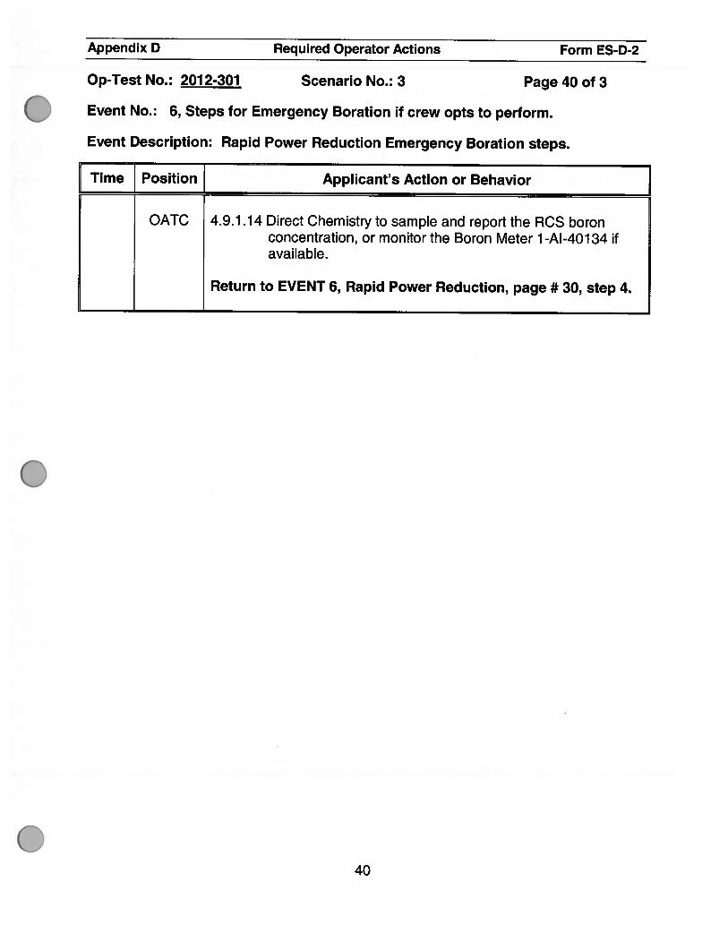
Event Description: Rapid Power Reduction Emergency Boration steps.
Time Position Applicant’s Action or Behavior
OATC 4.9.1.14 Direct Chemistry to sample and report the RCS boronconcentration, or monitor the Boron Meter 1 -Al-401 34 ifavailable.
Return to EVENT 6, Rapid Power Reduction, page # 30, step 4.
40

Appendix 0 Required Operator Actions Form ES-D-2
Op-Test No.: 201 2-301 Scenario No.: 3
Event No.: 7
Event Description: A DBA SGTR will occur on SG # 1 with complications. The TDAFWsteam supply from SG # 1 will not close requiring the crew to trip the TDAFW pump usingthe Trip and Throttle Valve. In addition, after depressurizing the RCS with PRZR spray torefill the PRZR and lower break flow, a PRZR spray will not close requiring the crew tostop RCP #4.
Time Position Applicant’s Action or Behavior
CREW Performs Immediate Operator Actions per 1 9000-C, E-0 Reactor Trip orSafety Injection.
SS Makes a page announcement of Reactor Trip.
OATC 1. Check Reactor Trip: (YES)
. Rod Bottom Lights — LIT• Reactor Trip and Bypass Breakers — OPEN. Neutron Flux — LOWERING
UO 2. Check Turbine Trip: (YES)
. All Turbine Stop Valves — CLOSED
UO 3. Check Power to AC Emergency Buses. (YES)
a. AC Emergency Busses — AT LEAST ONE ENERGIZED.
• 4l6OAClEBusses
b. AC Emergency Busses — ALL ENERGIZED.
. 4l6OVAClEBusses• 480V AC 1 E Busses
OATC 4. Check if SI is actuated. (YES)
• Any SI annunciators — LIT. SI ACTUATED BPLP window — LIT
SS Go to Step 6.
41

Appendix D Required Operator Actions Form ES-D-2
Op-Test No.: 2012-301 Scenario No.: 3
Event No.: 7
Event Description: A DBA SGTR will occur on SG # 1 with complications. The TDAFWsteam supply from SG # 1 will not close requiring the crew to trip the TDAFW pump usingthe Trip and Throttle Valve. In addition, after depressurizing the RCS with PRZR spray torefill the PRZR and lower break flow, a PRZR spray will not close requiring the crew tostop RCP # 4.
Time Position Applicant’s Action or Behavior
SS 6. Initiate the Foldout Page.CREW
SS 7. Perform the following:
OATC • OATC Initial Actions Page (Note to examiner, start page 43)
UO • UO Initial Actions Page (Note to examiner, start page 46)
NOTE: SS initiates step 8 after OATC/UO Initial Actions completed.
42

Appendix D Required Operator Actions Form ES-D-2
Op-Test No.: 2012-301 Scenario No.: 3
Event No.: 7
Event Description: A DBA SGTR will occur on SG # 1 with complications. The TDAFW
steam supply from SG # 1 will not close requiring the crew to trip the TDAFW pump using
the Trip and Throttle Valve. In addition, after depressurizing the RCS with PRZR spray to
refill the PRZR and lower break flow, a PRZR spray will not close requiring the crew to
stop RCP #4.
Time Position Applicant’s Action or Behavior
OATC PERFORMS OATC INITIAL ACTIONS
1. Check both trains of ECCS equipment — ALIGNING FOR INJECTIONPHASE: (YES)
. MLB indication
OATC 2. Check Containment Isolation Phase A — ACTUATED. (YES)
• CIA MLB indication
OATC 3. Check ECCS Pumps and NCP status:
a. CCPs RUNNING. (YES)
b. SI Pumps — RUNNING. (YES)
c. RHR pumps — RUNNING. (YES)
d. NCP — TRIPPED. (YES)
OATC 4. Verify CCW Pumps — ONLY TWO RUNNING TRAIN B. (YES)
43

Appendix 0 Required Operator Actions Form ES-D-2
Op-Test No.: 201 2-301 Scenario No.: 3
Event No.: 7
Event Description: A DBA SGTR will occur on SG # 1 with complications. The TDAFW
steam supply from SG # 1 will not close requiring the crew to trip the TDAFW pump using
the Trip and Throttle Valve. In addition, after depressurizing the RCS with PRZR spray to
refill the PRZR and lower break flow, a PRZR spray will not close requiring the crew to
stop RCP #4.
[ Time Position Applicant’s Action or Behavior 1OATC PERFORMS OATC INITIAL ACTIONS
5. Verify proper NSCW system operation: (YES)
a. NSCW Pumps - ONLY TWO RUNNING PER TRAIN.
b. NSCW TOWER RTN HDR BYPASS BASIN hand switches — INAUTO:
. HS-1669A
. HS-1668A
OATC 6. Verify Containment Cooling Units: (YES)
a. ALL RUNNING IN LOW SPEED. (YES)
. MLB indication
b. NSCW Cooler isolation valves — OPEN. (YES)
. MLB indication
OATC 7. Check Containment Ventilation Isolation.
a. Dampers and Valves — CLOSED. (YES)
44
Appendix 0 Required Operator Actions Form ES-D-2
Op-Test No.: 2012-301 Scenario No.: 3
Event No.: 7
Event Description: A DBA SGTR will occur on SG # 1 with complications. The TDAFWsteam supply from SG # 1 will not close requiring the crew to trip the TDAFW pump usingthe Trip and Throttle Valve. In addition, after depressurizing the RCS with PRZR spray torefill the PRZR and lower break flow, a PRZR spray will not close requiring the crew tostop RCP #4.
Time Position Applicant’s Action or Behavior
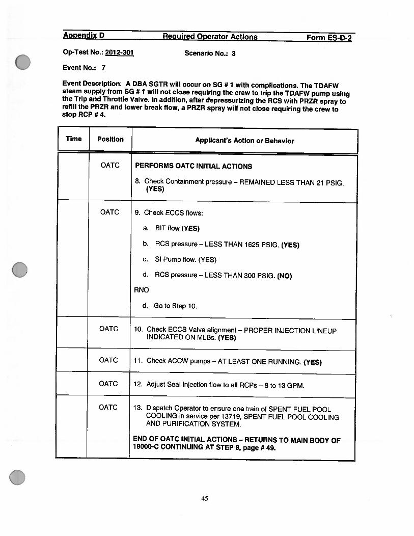
OATC PERFORMS OATC INITIAL ACTIONS
8. Check Containment pressure — REMAINED LESS THAN 21 PSIG.(YES)
OATC 9. Check ECCS flows:
a. BIT flow (YES)
b. RCS pressure — LESS THAN 1625 PSIG. (YES)
c. SI Pump flow. (YES)
d. RCS pressure — LESS THAN 300 PSIG. (NO)
RNO
d. GotoSteplO.
OATC 10. Check ECCS Valve alignment — PROPER INJECTION LINEUPINDICATED ON MLBs. (YES)
OATC 11. Check ACCW pumps — AT LEAST ONE RUNNING. (YES)
OATC 12. Adjust Seal Injection flow to all RCPs —8 to 13 GPM.
OATC 13. Dispatch Operator to ensure one train of SPENT FUEL POOLCOOLING in service per 13719, SPENT FUEL POOL COOLINGAND PURIFICATION SYSTEM.
END OF OATC INITIAL ACTIONS - RETURNS TO MAIN BODY OF19000-C CONTINUING AT STEP 8, page # 49.
45

Appendix D Required Operator Actions Form ES-D-2
Op-Test No.: 201 2-301 Scenario No.: 3
Event No.: 7
Event Description: A DBA SGTR will occur on SG # 1 with complications. The TDAFWsteam supply from SG # 1 will not close requiring the crew to trip the TDAFW pump usingthe Trip and Throttle Valve. In addition, after depressurizing the RCS with PRZR spray torefill the PRZR and lower break flow, a PRZR spray will not close requiring the crew tostop RCP #4.
Time Position Applicant’s Action or Behavior
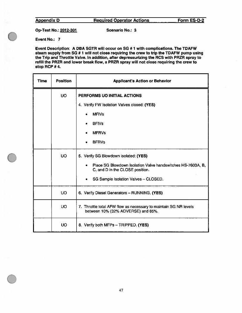
UO PERFORMS UO INITIAL ACTIONS
1. Check AFW Pumps — RUNNING. (YES)
. MDAFW Pumps
. TDAFW Pump, if required.
UO 2. Check NR level in at least one SG — GREATER THAN 10%.(32% ADVERSE). (YES)
UO 3. Check if main steamlines should be isolated: (NO)
a. Check for one of more of the following conditions:
Any steam line pressure LESS THAN OR EQUAL TO 585 PSIG.
Containment pressure — GREATER THAN 14.5 PSIG.
Low Steam Pressure SI/SLI — BLOCKED AND High SteamPressure Rate — ON TWO OR MORE CHANNELS OF ANYSTEAMLINE.
RNO
a. GotoStep4.
46
Appendix D Required Operator Actions Form ES-D-2
Op-Test No.: 201 2-301 Scenario No.: 3
Event No.: 7
Event Description: A DBA SGTR will occur on SG # 1 with complications. The TDAFWsteam supply from SG # 1 will not close requiring the crew to trip the TDAFW pump usingthe Trip and Throttle Valve. In addition, after depressurizing the RCS with PRZR spray torefill the PRZR and lower break flow, a PRZR spray will not close requiring the crew tostop RCP #4.
Time Position Applicant’s Action or Behavior
UO PERFORMS UO INITIAL ACTIONS
4. Verify FW Isolation Valves closed: (YES)
. MFIVs
. BFIVs
. MFRVs
. BFRVs
UO 5. Verify SG Blowdown isolated: (YES)
. Place SG Blowdown Isolation Valve handswitches HS-7603A, B,C, and D in the CLOSE position.
• SG Sample Isolation Valves — CLOSED.
UO 6. Verify Diesel Generators — RUNNING. (YES)
UO 7. Throttle total AFW flow as necessary to maintain SG NR levelsbetween 10% (32% ADVERSE) and 65%.
UO 8. Verify both MFPs — TRIPPED. (YES)
47

Appendix D Required Operator Actions Form ES-D-2
Op-Test No.: 2012-301 Scenario No.: 3
Event No.: 7
Event Description: A DBA SGTR will occur on SG # 1 with complications. The TDAFWsteam supply from SG # 1 will not close requiring the crew to trip the TDAFW pump usingthe Trip and Throttle Valve. In addition, after depressurizing the RCS with PRZR spray torefill the PRZR and lower break flow, a PRZR spray will not close requiring the crew tostop RCP #4.
Time Position Applicant’s Action or Behavior
UO 9. Check Main Generator Output Breakers — OPEN. (YES)
OATC BACK TO 19000-C PROCEDURE MAIN BODY, page # 49.uO
48

Appendix D Required Operator Actions Form ES-D-2
Op-Test No.: 2012-301 Scenario No.: 3
Event No.: 7
Event Description: A DBA SGTR will occur on SG # 1 with complications. The TDAFWsteam supply from SG # 1 will not close requiring the crew to trip the TDAFW pump using
the Trip and Throttle Valve. In addition, after depressurizing the RCS with PRZR spray to
refill the PRZR and lower break flow, a PRZR spray will not close requiring the crew to
stop RCP # 4.
Time Position Applicant’s Action or Behavior
CREW 8. Initiate the Continuous Actions Page.
OATC 9. Check RCS temperature stable at or trending to 557°F.
-OR-
Without RCP(s) running — RCS WR COLD LEG TEMPERATURES.
RNO (IF needed)
9. IF temperature is less than 557°F and lowering, THEN perform thefollowing as necessary:
a. Stop dumping steam.
b. Perform the following as appropriate:
IF at least one SG NR level greater than 10%(32% ADVERSE), THEN lower total feed flow.
-OR
IF all SG NR levels less than 10% (32% ADVERSE), THENlower total feed flow to NOT less than 570 gpm.
c. If cooldown continues, THEN close MSIVs and BSIVs.
d. If temperature greater than 557°F and rising, THEN dump steam.
49

Appendix D Required Operator Actions Form ES-D-2
Op-Test No.: 2012-301 Scenario No.: 3
Event No.: 7
Event Description: A DBA SGTR will occur on SG # 1 with complications. The TDAFWsteam supply from SG # 1 will not close requiring the crew to trip the TDAFW pump usingthe Trip and Throttle Valve. In addition, after depressurizing the RCS with PRZR spray torefill the PRZR and lower break flow, a PRZR spray will not close requiring the crew tostop RCP #4.
Time Position Applicant’s Action or Behavior
OATC CAUTION: A PRZR PORV Block Valve which was closed to isolate anexcessively leaking or open PRZR PORV should not beopened unless used to prevent challenging the PRZRSafeties.
10. Check PRZR PORVs, Block Valves, and Spray Valves:
a. PRZR PORVs - CLOSED AND IN AUTO. (YES)
b. Normal PRZR Spray Valves — CLOSED. (YES)
c. Power to at least one Block Valve — AVAILABLE. (YES)
d. PRZR PORV Block Valves — AT LEAST ONE OPEN. (NO)
RNO
d. Verify open at least one PRZR PORV Block Valve when PRZRpressure is greater than 2185 psig.
OATC 11. Check if RCPs should be stopped:
a. ECCS Pumps - AT LEAST ONE RUNNING: (YES)
• CCPorSI Pump
b. RCS pressure — LESS THAN 1375 PSIG. (NO)
RNO
b. GotoStepl2.
Note to examiner: It is expected RCP pressure will be above 1375 psigat this time.
50
Appendix D Required Operator Actions Form ES-D-2
Op-Test No.: 201 2-301 Scenario No.: 3
Event No.: 7
Event Description: A DBA SGTR will occur on SG # 1 with complications. The TDAFWsteam supply from SG # 1 will not close requiring the crew to trip the TDAFW pump usingthe Trip and Throttle Valve. In addition, after depressurizing the RCS with PRZR spray torefill the PRZR and lower break flow, a PRZR spray will not close requiring the crew tostop RCP#4.
Time Position Applicant’s Action or Behavior
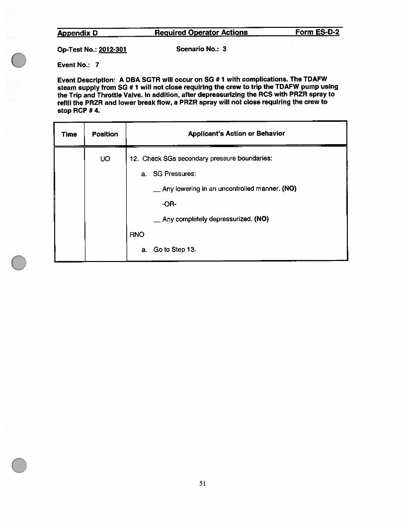
UO 12. Check SGs secondary pressure boundaries:
a. SG Pressures:
Any lowering in an uncontrolled manner. (NO)
-OR
Any completely depressurized. (NO)
RNO
a. GotoStepl3.
51

Appendix D Required Operator Actions Form ES-D-2
Op-Test No.: 201 2-301 Scenario No.: 3
Event No.: 7
Event Description: A DBA SGTR will occur on SG # 1 with complications. The TDAFWsteam supply from SG # 1 will not close requiring the crew to trip the TDAFW pump usingthe Trip and Throttle Valve. In addition, after depressurizing the RCS with PRZR spray torefill the PRZR and lower break flow, a PRZR spray will not close requiring the crew tostop RCP # 4.
Time Position Applicant’s Action or Behavior
UO 13. Check SG Tubes intact:
a. Direct Chemistry to take periodic activity samples of all SGs oneat a time.
b. Secondary Radiation — NORMAL. (NO)
• MAIN STEAM LINE MONITORS
• RE-13120(SG1)• RE-13121 (SG2)• RE-13122 (SG3)• RE-13119(SG4)
• CNDSR AIR EJCTR/STM RAD MONITORS:
• RE-12839• RE-12839D (if on scale)• RE-12839E (if on scale)
• STM GEN LIQ PROCESS RAD:
• RE-0019 (Sample)• RE-0021 (Blowdown)
• SG sample radiation:
RNO
b. Go to 19030-C, E-3 STEAM GENERATOR TUBE RUPTURE.
Note to examiner: 19030-C, E-3 SGTR actions are on followingattachment.
52

Appendix D Required Operator Actions Form ES-D-2
Op-Test No.: 2012-301 Scenario No.: 3
Event No.: 7
Event Description: DBA SGTR actions from 19030-C, E-3 STEAM GENERATORTUBE RUPTURE
Time Position Applicant’s Action or Behavior
FEW 1. Initiate the following:
. Continuous Actions and Foldout Page.
• Critical Safety Function Status Trees per 1 9200-C, F-OCRfl1CALSAFEPI FIJNCflON STA11JSTF.
2. Initiate NMP-EP-1 10, Ei1VIcLAlFcATIONDETSRMINATION AND lNrnALCTlON.
OAIC 3. Maintain Seal Injection flow to all FCF—8 to 13GPM.
QA1O 4. Check if RDF should be stopped:
a. EtSPumps-ATLEASTOF\ERUNNING: (YES)
ccPor Sip Pump
b. FtS pressure — LTHAN 1375 FSIG. (NO)
FD
b. IFFtSpressure lowers to less than 1375 psig prior to initiation ofRScooldown in Step 17.11-EN stop all RDFand return to Step in effect.
Go to Step 5.
53

Appendix D Required Operator Actions Form ES-D-2
Op-Test No.: 2012-301 Scenario No.: 3
Event No.: 7
Event Description: DBA SGTR actions from 19030-C, E-3 STEAM GENERATOR
TUBE RUPTURE
Time Position Applicant’s Action or Behavior
UO 5. Identify ruptured SG(s) by any of the following conditions.
Unexpected rise in any SG NR level.
High radiation from any 93 sample.
High radiation from any 93 steamline.
High radiation from any 93 blowdown line.
Note to examiner: 93 # 1 level will be rising with AFW flow throttled.However, this is a hard call for the candidate until the TDARV steamsupply is isolated in later steps since steam is being supplied to theTDAFW pump causing the level rise to NOT be as pronounced.
CAUTION: At least one 93 should be maintained available for FtScooldown.
UO 6. Isolate ruptured SO(s):
Critical a. Adjust ruptured SG ARV(s) controller setpoint to 1160psig (pot setting 7.73)
b. check ruptured SGARV(s) —CLCD.
PV-3000 (SG 1)
PV-301 0 (SO 2)
PV-3020 (SO 3)
PV-3030 (SO 4)
54
Appendix D Required Operator Actions Form ES-D-2
Op-Test No.: 2012-301 Scenario No.: 3
Event No.: 7
Event Description: DBA SGTR actions from 19030-C, E-3 STEAM GENERATOR
TUBE RUPTURE
Time ] Position [ Applicant’s Action or Behavior
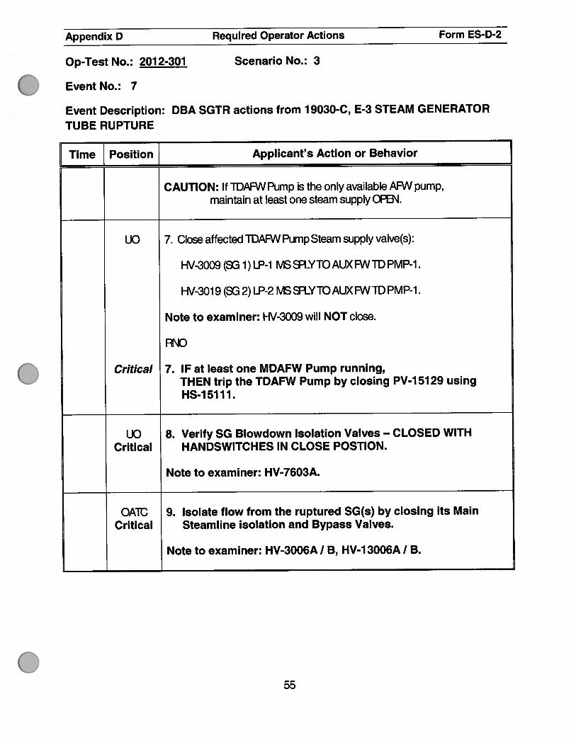
CAUTION: If TDAFVV Pump is the only available AFW pump,maintain at least one steam supply 0P6’J.
UO 7. Close affected TDAFW Pump Steam supply valve(s):
HV-3009 (SG 1) LP-1 MS SIYTO AUX FW TD PMP-1.
HV-301 9 (SG 2) LP-2 MS YTO AUX FW TD PMP-1.
Note to examiner: HV-3009 will NOT close.
AND
Critical 7. IF at least one MDAFW Pump running,THEN trip the TDAFW Pump by closing PV-1 51 29 usingHS-15111.
UO 8. Verify SG Blowdown Isolation Valves — CLOSED WITHCritical HANDSWITCHES IN CLOSE POSTION.
Note to examiner: HV-7603A.
OAIC 9. Isolate flow from the ruptured SG(s) by closing its MainCritical Steamline isolation and Bypass Valves.
Note to examiner: HV-3006A I B, HV-1 3006A I B.
55

Appendix D Required Operator Actions Form ES-D-2
Op-Test No.: 2012-301 Scenario No.: 3
Event No.: 7
Event Description: DBA SGTR actions from 19030-C, E-3 STEAM GENERATORTUBE RUPTURE
Time Position { Applicant’s Action or Behavior
CAUTIONS:
. This procedure should be performed in a timely manner to assurethat break flow in the ruptured SG(s) is terminated before waterenters the SGs main steam piping.
. Any ruptured SG that is also faulted, should remain isolated duringsubsequent recovery actions unless needed for FCScooldown or33 activity sample.
UO 10. Check ruptured SG(s) level:
a. 33 NR level —GFEATBR11-IAN 1CY%(32%ADV6. (YES)
b. Step feed flow to ruptured 33(s).
Close the TDAFW and MDAFW valves to SG # 1.Critical
(Note to examiner: 1 HS-51 22A and 1 HS-51 39A)
UO 11. Check ruptured SG(s) pressure — GFEATBTl-lAN 290 FSIG.(YES)
NOTE: When the low steamline pressure Sl,SLI is blocked, mainsteamline isolation will occur is the high steam pressure ratesetpoint is exceeded.
56

Appendix 0 Required Operator Actions Form ES-D-2
Scenario No.: 3Op-Test No.: 2012-301
Event No.: 7
Event Description: DBA SGTR actions from 19030-C, E-3 STEAM GENERATORTUBE RUPTURE
Time Position Applicant’s Action or Behavior
12. Check if low steamline pressure SI/SLI should be blocked:
UO a. Steam dumps - AVAILAftE (YES)
QAIC b. PFØpressure — L11-IAN 2000 FlG. (YES)
UC c. High steam pressure rate alarms — CLEAR. (YES)
d. Block low steam line pressure SI/SLI using the following:
. H4O068
. [€-40069
UC 13. Align steam Dumps for FCScooldown:
a. lFSteam Dumps are inTAVG mode, (YES)11-EN
UO 1) Match demand on SG Header Pressure Controller PIC-507 andED demand meter U 1-500.
UC 2) Tinsfer Steam Dumps toSTM P1mode usingHS-500C.
b. FtS temperature — GFEATBTfHAN 550°F.
UO c. AsFtScooldown is initiated, hold HS-0500A and l-S05008 in theBYPA INTBiD( position until FCS temperature is less than550°F.
UC 14. Raise intact SG levels prior to maximum rate cooldown.
57

Appendix 0 Required Operator Actions Form ES-D-2
Op-Test No.: 2012-301 Scenario No.: 3
Event No.: 7
Event Description: DBA SGTR actions from 19030-C, E-3 STEAM GENERATORTUBE RUPTURE
Time Position Applicant’s Action or Behavior
OATC 15. Check at least one R:F—RUNNING. (YES)
SS 16. Determine required core exit temperature for cooldown.
Lowest Ruptured SG Core ExitPressure (psig) Temperature (°F)
1200 and greater 530
llOOto 1199 518
1000 to 1099 506
900 to 999 493
800 to 899 479
700 to 799 463
600 to 699 445
500 to 599 424
400 to 499 399
300 to 399 366
290 to 299 350
Note to examiner: Expect to pick either 518 or 506.
58

Appendix D Required Operator Actions Form ES-D-2
Op-Test No.: 2012-301 Scenario No.: 3
Event No.: 7
Event Description: DBA SGTR actions from 19030-C, E-3 STEAM GENERATORTUBE RUPTURE
Time Position Applicant’s Action or Behavior
UC 17. Initiate FtScooldown:
a. Dump steam to Condenser from intact SG(s) at maximum rateusing Steam Dumps by slowly raising demand onPC-507.
OA1C 18. Check if RScooldown should be stopped:
a. Core Exit ICs - LS11-iAN FE)UIFED TEMP611JFE.(NOT AT THIS TIME)
FO
a. SM-EN core exits are less than required,Ti-EN perform steps 18.b and 18.c.
Note to examiner: This will take several minutes to reach GETtargettemperate of either 518 or 506.
UC b. Stop FtScooldown.
c. Maintain Core Exit TCs- LThANUITBv1PS1UE
Note to examiner: The UC will use steam dumps to maintain.
59

Appendix D Required Operator Actions Form ES-D-2
Op-Test No.: 2012-301 Scenario No.: 3
Event No.: 7
Event Description: DBA SGTR actions from 19030-C, E-3 STEAM GENERATOR
TUBE RUPTURE
Time Position Applicant’s Action or Behavior
UO 19. Check intactSG levels:
a. NR level - ATLEASrOI\EGFEATBRTHAN 10%. (32%ADV)(YES)
b. Maintain NR levels between jQD/ (32’/oADV) and 65%.
c. NR level — AFW RlNG IN AN UNOONTRDLLED MANN8R. (NO)
AND
c. Go to Step 20.
DAlE 20. Check PFØFOFWsand Block Valves:
a. Power to Pt F’(JWBIock Valves—AVAILABLE. (YES)
b. R-iFcR’/s-GLcD. (YES)
C. [-RI-I RDFW Block Valves - AT LEAST O1’.E OFEN. (NO)
AND
c. IFBlockValve NDT closed to isolate an excessively leaking or openFi-ZH RDRJ, AND WFB\J Fi-11-I pressure is greater than 2185 psig,TI-EN verify open at least one FORJ Block Valve.
60

Appendix D Required Operator Actions Form ES-D-2
Op-Test No.: 2012-301 Scenario No.: 3
Event No.: 7
Event Description: DBA SGTR actions from 19030-C, E-3 STEAM GENERATOR
TUBE RUPTURE
Time Position { Applicant’s Action or Behavior
CAUTIONS:
If offsite power is lost after SI reset, action is required to restart thefollowing Fequipment if plant conditions require their operation.
• FHRPumps
. SiPumps
. Post-LOCA Cavity Purge Units
. Containment Coolers in low speed (Started in high speed on a UVsignal)
. Chilled Water Pumps (If CR1 is reset)
OAIC 21. ResetSl.
CAUTION:
Repositioning Phase A Isolation Valves may cause radiation problemsthroughout the plant.
OAIC 22. Reset Containment Isolation Phase A.
61

Appendix D Required Operator Actions Form ES-D-2
Op-Test No.: 2012-301 Scenario No.: 3
Event No.: 7
Event Description: DBA SGTR actions from 19030-C, E-3 STEAM GENERATORTUBE RUPTURE
Time Position Applicant’s Action or Behavior
UO 23. Establish Instrument Air to Containment.
a. Instrument Air pressure — GFEATTHAN 100 PG. (YES)
b. Open INSTRAIRCNMT ISO VLV HV-9378. (YES)
c. Verify PFØSpray Valves operating as required. (YES)
OATC 24. Check if R1-F( Pumps should be stopped:
a. FfR Pumps - ANY RUNNING Wfll-1 SUDTION ALIGNED TO RAT.(YES)
b. FCS pressure - GFEA1THAN 300 FSK3. (YES)
c. Stop RI-FPumps.
OAIC 25. IFFtSpressure lowers in an uncontrolled manner to less than 300psig.
ThEN restart RI-F Pumps.
62
Appendix D Required Operator Actions Form ES-D-2
Op-Test No.: 2012-301 Scenario No.: 3
Event No.: 7
Event Description: DBA SGTR actions from 1 9030-C, E-3 STEAM GENERATOR
TUBE RUPTURE
[me Position Applicant’s Action or Behavior
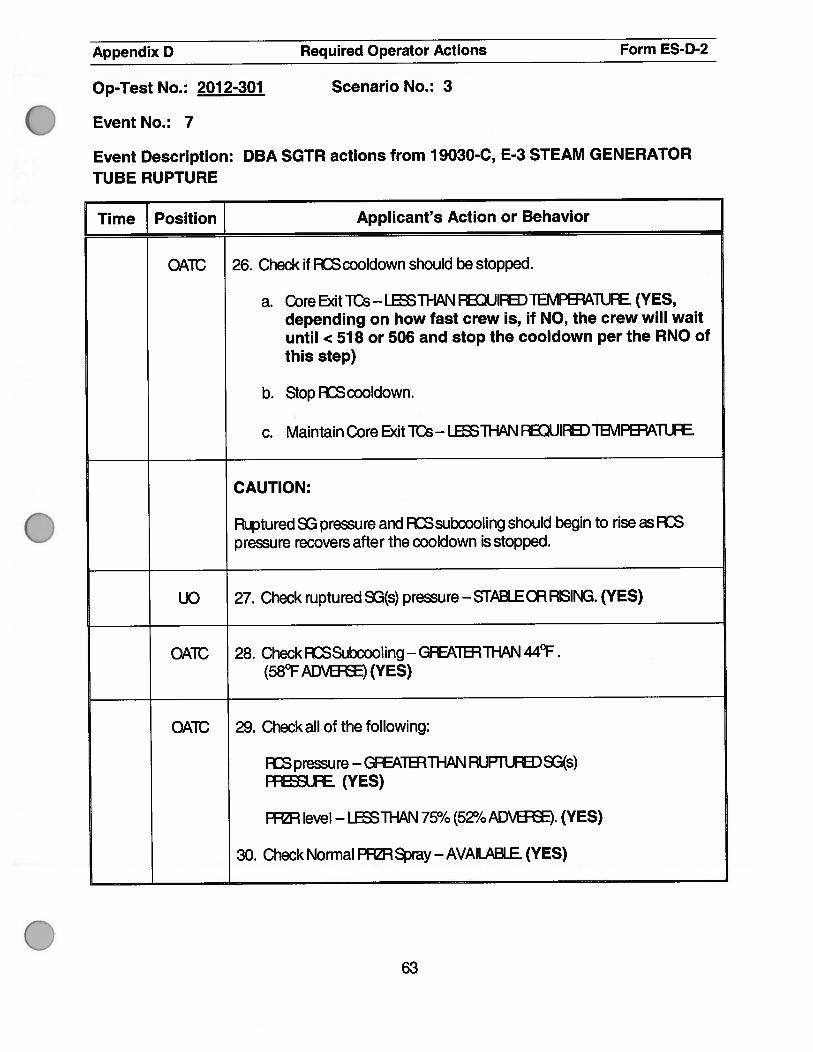
OATC 26. Check if FtScooldown should be stopped.
a. Core Exit its - LESS11-IAN FEDIJIFED TEMPB’AilJFE. (YES,depending on how fast crew is, if NO, the crew will waituntil < 518 or 506 and stop the cooldown per the RNO ofthis step)
b. Stop FtScooldown.
c. Maintain Core Exit its- LESSTHAN lDUlFEDTB1PBA1UE
CAUTION:
Ruptured SG pressure and ADS subcooling should begin to rise as ADSpressure recoveis after the cooldown is stopped.
UO 27. Check ruptured SG(s)pressure—STABLECRRSING.(YES)
OATC 28. Check ASSubcooling - GFEATBR THAN 44°F.(58°F ADVS) (YES)
OATC 29. Check all of the following:
ADS pressure - GFEATBTfl-IAN RUP1UED 3(s)FfJE (YES)
FHa-1 level - Li1-IAN 75% (52% ADVB). (YES)
30. Check Normal PIRray—AVAlLABLE. (YES)
63

Appendix D Required Operator Actions Form ES-D-2
Op-Test No.: 2012-301 Scenario No.: 3
Event No.: 7
Event Description: DBA SGTR actions from 19030-C, E-3 STEAM GENERATORTUBE RUPTURE
Time Position [ Applicant’s Action or Behavior
OATC 31. Depressurize RDS using Normal PFSpray to refill PFR.
Critical a. Spray PRZR with maximum available spray.
Note to examiner: OA1ID must fully open BOTH spray valves to satisfythe critical step.
b. Normal PFØR Spray - EFFB’JflVE AT FEDLJCING ADS PFLFE(YES)
c. Go to Step 37.
OATC 37. Check if AF\IY of the following conditions are satisfied.
BOTH of the following:
Critical 1) RCS pressure — LESS THAN RUPTURED SO(s)PRESSURE.
Critical 2) PRZR level — GREATER THAN 9%. (37% ADVERSE)
-OR
FcsSubcooling — LTHAN 24oF (38°FAD’)
-OR-
Critical PRZR level — GREATER THAN 75% (52% ADVERSE)
Note to examiner: Due to the nature ofaDBAS3TlRat Vogtle, it will bevery close on whether it is BOTH FCP pressure & Fi-iH level as highlightedabove OR PFØ level > 75% only. The OATC will close the spray valvesbased on the 1st parameter obtained.
64

Appendix D Required Operator Actions Form ES-D-2
Op-Test No.: 2012-301 Scenario No.: 3
Event No.: 7
Event Description: DBA SGTR actions from 19030-C, E-3 STEAM GENERATORTUBE RUPTURE
Time [ Position_J Applicant’s Action or Behavior
QAIC 38. Terminate RSdepressurization:
a. Verify Normal PFRSpray valve(s) — OLcD. (NO)
FD
Critical a. IF a Normal Spray valve can NOT be closed,THEN stop RCP 4.
IF PRZR pressure continues lowering uncontrollably,THEN stop RCP 1.
Note to examiner: It isexpected that RSpressure will be rising afterstopping RDP#4. If NOT, then stopping RDP# 1 will also be a critical step.
b. Verify PF1 FCPsJ(s) CLCD. (YES)
c. Block COFS.
d. GheckAuxiliary Spray— lNMGE(NO)
FD
d. Go to step 39.
OAIC 39. Check FtS pressure - RISING. (YES)
CAUTION
BXSR.cWSHQIJLD BETBRMINATED when termination criteria aresatisfied to prevent overfilling of the ruptured S.
65

Appendix D Required Operator Actions Form ES-D-2
Op-Test No.: 2012-301 Scenario No.: 3
Event No.: 7
Event Description: DBA SGTR actions from 19030-C, E-3 STEAM GENERATOR
TUBE RUPTURE
Time Position Applicant’s Action or Behavior
OATC 40. Check if ECCS flow should be terminated.
a. RCS Subcooling — GREATER THAN 24°F (38°F ADVERSE)(YES)
b. Secondary Heat Sink:
UO Total feed flow to SGs — GREATER THAN 570 GPMAVAILABLE (YES)
-OR
NR level in at least one intact SG — GREATER THAN 10%(32% ADVERSE) (YES)
OATC c. RCS pressure — STABLE OR RISING. (YES)
d. PRZR level - GREATER THAN 9% (37% ADVERSE) (YES).
OATC 41. Stop ECCS Pumps and place in standby.
. SI Pumps
. All but one CCP
OATC 42. Establish charging flow:
a. Check Instrument Air — AVAILABLE.
b. Open CCP normal miniflow isolation valves.
. HV-81 1 1A — CCP-A MINIFLOW
. HV-81 11 B — CCP-B MINIFLOW
. HV-81 10 - CCP A & B COMMON MINIFLOW
66

Appendix D Required Operator Actions Form ES-D-2
Op-Test No.: 2012-301 Scenario No.: 3
Event No.: 7
Event Description: DBA SGTR actions from 19030-C, E-3 STEAM GENERATOR
TUBE RUPTURE
j Time Position Applicant’s Action or Behavior
OATC 42. continued
c. Close CCP alternate minif low valves:
. HV-8508A - CC P-A RV TO RWST ISOLATION
. HV-8508B — CCP-B RV TO RWST ISOLATION
d. Verify white Pressure Control Mode light — NOT LIT:
. HV-8508A - CCP-A RV TO RWST ISOLATION
. HV-8508B - CCP-B PC TO RWST ISOLATION
e. Close BIT DISCH ISOLATION VALVES:
. HV-8801A
. HV-8801 B
f. Set SEAL FLOW CONTROL HC-182 to maximum seal flow(HC-0182 closed).
g. Open CHARGING TO RCS ISOLATION valves:
. HV-8105
. HV-8106
OATC 43. Control charging flow to maintain PRZR level and Seal injectionflow to all RCPs—8to 13GPM.
67

Appendix D Required Operator Actions Form ES-D-2
Op-Test No.: 2012-301 Scenario No.: 3
Event No.: 7
Event Description: DBA SGTR actions from 19030-C, E-3 STEAM GENERATORTUBE RUPTURE
[ Time Position [ Applicant’s Action or Behavior
OATC 44. Check ECCS flow not required:
a. RCS Subcooling — GREATER THAN 24°F (38°F ADVERSE)(YES)
b. PRZR level - GREATER THAN 9% (37% ADVERSE) (YES)
END OF EVENT 7, END OF SCENARIO #3.
68