Embed Size (px)
Citation preview

Test and Inspection
VOA6-SM Variable Optical Attenuator
User’s Guide
2
Limited Warranty
WarrantyAll NOYES test equipment products are warranted for a period of (1) one year from the date of delivery to the end user. Extended warranties start at the end of the standard (1) one year warranty period.
1 year, 2 year, and 4 year extended warranties are available for NOYES products with or without annual calibration included.
Any product that is found defective within the warranty period will, at the discretion of AFL, be repaired or replaced. Warranty will be voided if the product has been repaired or altered by other than an authorized NOYES product repair facility, if the void sticker has been compromised, or which have been subject to misuse, negligence, or accident.
In no case shall AFL liabilities exceed the original purchase price.
CE InformationThese instruments have been designed and tested to comply with the relevant sections of any applicable specifications including full compliance with all essential requirements of all applicable EU Directives.
Returning EquipmentTo return equipment, please contact NOYES to obtain additional information and a Service Request (S.R.) number. To allow us to serve you more efficiently, please include a brief description specifying the reasons for the return of the equipment.
AFL Telecommunications
NOYES Test and Inspection 16 Eastgate Park RoadBelmont, NH 03220Tel: 800-321-5298 603-528-7780Fax: 603-528-2025
Safety Information
CAUTION! To avoid serious eye injury, never look directly into the optical outputs of fiber optic network equipment, test equipment, patch cords, or test jumpers. Always assume that optical outputs are on.
NOTICE! VOA6-SM Variable Optical Attenuators contain no user serviceable parts. Except for changing batteries and cleaning optical ports, these units must be returned to NOYES or authorized agents for repair and calibration.
IMPORTANT! Proper care in handling should be taken when using any precision optical test equipment. Scratched or contaminated optical connectors can impact the performance of the instrument. It is important to keep the dust caps in place when the unit is not being used.

3
Table of ContentsSafety Information. . . . . . . . . . . . . . . . . . . . . . . . . . . . . . . . . . . . . . . . . . .2Getting Started: Front Panel Keys . . . . . . . . . . . . . . . . . . . . . . . . . . . . . . .4Getting Started: Display Features. . . . . . . . . . . . . . . . . . . . . . . . . . . . . . . .5Setup: Edit l Table . . . . . . . . . . . . . . . . . . . . . . . . . . . . . . . . . . . . . . . . . .6Setup: Set Reference Level . . . . . . . . . . . . . . . . . . . . . . . . . . . . . . . . . . . .7Setup: Edit Reference Level . . . . . . . . . . . . . . . . . . . . . . . . . . . . . . . . . . . .8Setup: Relative/Absolute Attenuation . . . . . . . . . . . . . . . . . . . . . . . . . . . . .9Setup: LCD backlight adjustment . . . . . . . . . . . . . . . . . . . . . . . . . . . . . . . .9Operation: Absolute Attenuation . . . . . . . . . . . . . . . . . . . . . . . . . . . . . . . .10Operation: Relative Attenuation . . . . . . . . . . . . . . . . . . . . . . . . . . . . . . . . .11Application: Measuring Operating Limits. . . . . . . . . . . . . . . . . . . . . . . . . . .12Application: Testing of Optical Margin. . . . . . . . . . . . . . . . . . . . . . . . . . . . .13Recommended Accessories. . . . . . . . . . . . . . . . . . . . . . . . . . . . . . . . . . . .14Cleaning Tips . . . . . . . . . . . . . . . . . . . . . . . . . . . . . . . . . . . . . . . . . . . . . .14Maintenance Tips . . . . . . . . . . . . . . . . . . . . . . . . . . . . . . . . . . . . . . . . . . .16Recharging Battery . . . . . . . . . . . . . . . . . . . . . . . . . . . . . . . . . . . . . . . . . .16Repair and Calibration . . . . . . . . . . . . . . . . . . . . . . . . . . . . . . . . . . . . . . . .16Troubleshooting . . . . . . . . . . . . . . . . . . . . . . . . . . . . . . . . . . . . . . . . . . . .17
© 2010-2011, AFL, all rights reserved. VOA6-SM-SM-1000 Revision 1B, 2010-04-20

4
Getting Started: Front Panel Keys
The use of each key is summarized in the table below.
KEY SYMBOL KEY NAME KEY FUNCTION
Power • Press and hold (approx. 2 sec.) to turn on/off• Press and release to activate/deactivate the auto-off functionThe unit will power off after 10 minutes of inactivity
MENU/ENTER
Menu/Confirm • Press to access menu or sub-menu• Press to confirm/save selection• In the “Set REF Level” sub-menu, this key is used as Right Tab key: Press to move the selection cursor to highlight next digit in the displayed reference value to be changed by the Up and Down arrow keys
Arrow keys The arrow keys are used to navigate menu items and change setup parameters• Press to select function or value • Press to increase/decrease value
CANCEL Exit/Cancel Press to revert to the previous menu
l Wavelength Press to select one of the factory calibrated wavelengths. When the wavelength setting is changed, the VOA6-SM adjusts its optical filter to maintain the displayed attenuation at the new wavelength.
Rotating Dial • Rotate clockwise to increase attenuation value• Rotate counterclockwise to decrease the valueThe attenuation step is 0.05dB
Getting Started: Test Ports
PORT1 PORT2 9VUSB
Input/Output ports The optical input/output ports are used to connect the VOA6-SM to the receiver or transmitter end of the system under test
Power port - for external power supply.The supplied AC adapter powers the unit only (battery is not internally rechargeable).
USB port Used by manufacturer calibration services

5
Getting Started: Display Features
Auto-off icon is displayed when the auto-off function is activated
Auto-off icon is not displayed when the auto-off function is deactivated
Current wavelength(available: 1310, 1490, 1550, 1625 nm)
Current wavelength(available: 1310, 1490, 1550, 1625 nm)
External Power icon is displayed when the VOA6-SM operates from the AC adapter (auto-off function is invalid while using AC)
Battery icon is displayed when the VOA6-SM operates from the Li-Ion battery
- full battery
- low battery (requires charging)
Relative attenuation value in dBr
Absolute attenuation value in dBdB mode displays the actual attenuation at a given setting (2 to 60 dB)
Reference value in dBdBr is dB “relative” to the reference attenuation level

6
Setup: Edit l Table
• Press the MENU/ENTER key to access the Menu
screen - 1
• Note that the <Edit l Table> option - 2 is highlighted
• Press the MENU/ENTER key again to access the
Wavelengths sub-screen - 3 that displays the status of each wavelength -<Show> or <Hide>
• Use the arrow keys to highlight the desired wavelength
• Press the MENU/ENTER key to display the Show/
Hide sub-screen - 4 • Use the arrow keys to highlight the desired option
<Show> or <Hide>
Note: When a wavelength is set to <Hide>, the VOA6-SM doesn’t show it when switching the wavelengths.
• Press the MENU/ENTER key to save selection
• Press the CANCEL key to exit the Menu mode
Menu screen
Wavelengths sub-screen
Show/Hide sub-screen
1
2
3
4

7
Menu screen
Set REF screen
Test screen
Setup: Set Reference Level
• Press the MENU/ENTER key to access the
Menu screen - 1 • Use the arrow key to highlight the Set REF
Level option - 2 • Press the MENU/ENTER key to display the Set
REF Level screen - 3
• Note that
– <Set REF Level> option - 4 is highlighted
– reference level value (dB) - 5 is displayed
• If the displayed reference level value - 5 is acceptable, press the MENU/ENTER key to set and return to the test screen
– Note how screen changes to display
0.00 dBr - 6
1
2
3
4
5
6
7

8
Menu screen
Set REF screen
Editor screen
Setup: Edit Reference Level
• Press the MENU/ENTER key to access the
Menu screen - 1 • Use the arrow key to highlight the Set REF
Level option - 2 • Press the MENU/ENTER key to display the Set
REF Level screen - 3
• Use the arrow key to highlight the Edit REF
Level option - 4 • Press the MENU/ENTER key to display the
editor screen - 5 • Edit the displayed reference value as needed
– Use the MENU/ENTER key as Right Tab key - press to move the selection cursor to highlight next digit in the displayed reference value to be changed
– Use the arrow keys to increase/decrease value
• Press the MENU/ENTER to save edits and exit the editor screen
2
4
1
3
5
9
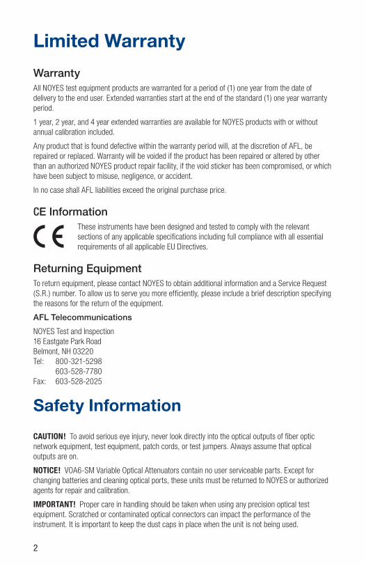
Setup: Relative/Absolute Attenuation
• Press the MENU/ENTER key to access the
Menu screen - 1 • Use the arrow key to highlight the <Show
dB/dBr> option - 2 • Press the MENU/ENTER key to display the dB/
dBr screen - 3
• Use the arrow keys to highlight <dB> or <dBr> option
• Press the MENU/ENTER key to set and return to the test screen
dB/dBr screen
Menu screen
Menu screen
Backlight screen
3
1
2
Setup: LCD backlight adjustment
• Press the MENU/ENTER key to access the
Menu screen - 1 • Use the arrow key to highlight the <Set
Backlight> option - 2 • Press the MENU/ENTER key to access the
Backlight screen - 3 • Use arrows to adjust the lightness of LCD
screen
• When done, press MENU/ENTER again to save settings
• Press CANCEL to exit Menu mode
3
1
2

10
Operation: Absolute Attenuation
Absolute attenuation level (dB) is set at calibration time. It ranges from minimum attenuation level (unit insertion loss) up to maximum attenuation level ( 60dB).
Absolute Attenuation Illustrative Example:
1 Connect an optical light source - OLS and optical power meter - OPM (or system under test) to the ports on the VOA6-SM attenuator using the appropriate jumper cable.
2 Set the OPM, OLS, and VOA6-SM to the desired test wavelength.
3 Make sure your OPM displays loss in dBm.
4 Set the VOA6-SM to operate in the Absolute attenuation (dB) mode.
5 Use the Set Reference function on the VOA6-SM to set the reference level.
6 Turning the thumbwheel clockwise increases attenuation level (attenuation step is 0.05 dB) applied to the optical signal traveling through the attenuator (neutral density filter).
7 The VOA6-SM updates the display with the current attenuation level (dB) real-time.
Example I
Equipment Setup:
• VOA6-SM insertion loss =1.55 dB
• Power into attenuator = +10 dBm
• Power out attenuator = (Power In) – (attenuation setting)
Example Values:
Attenuation (dB) Power In (dBm) Power Out (dBm)1.55 +10.00 +8.45
2.00 +10.00 +8.00
5.00 +10.00 +5.00
15.00 +10.00 -5.00
20.00 +10.00 -10.00
30.00 +10.00 -20.00
40.00 +10.00 -30.00
50.00 +10.00 -40.00
55.00 +10.00 -45.00
60.00 +10.00 -50.00

11
Operation: Relative Attenuation
The Relative attenuation level (dBr) is the sum of the Absolute attenuation level plus user supplied attenuation offset.
The Relative attenuation is used to allow the operator to view the relative output power level (dBr) based on the attenuation setting.
If in the Example I, we set the VOA6-SM to a reference value of 5 dB, the dBr readings are:
Attenuation (dB) Power In (dBm) Power Out (dBm) Relative Attenuation (dBr)1.55 +10.00 +8.45 +3.45
2.00 +10.00 +8.00 +3.00
5.00 +10.00 +5.00 0.00
15.00 +10.00 -5.00 -10.00
20.00 +10.00 -10.00 -15.00
30.00 +10.00 -20.00 -25.00
40.00 +10.00 -30.00 -35.00
50.00 +10.00 -40.00 -45.00
55.00 +10.00 -45.00 -50.00
60.00 +10.00 -50.00 -55.00
Relative attenuation (dBr) mode use example:
1 The user connects a high power source to the VOA6-SM attenuator and a fiber network.
2 Then the user turns the thumbwheel clockwise to attenuate the level applied to the network.
3 At the point the system begins to function with no errors, the user reads the absolute attenuation level (dB) directly from the VOA6-SM.
4 Then the user sets the reference level to the current attenuation setting using the VOA6-SM [Set REF Level] function.
5 Then the user turns the thumbwheel clockwise to further attenuate the level applied to the network.
6 The user stops when the system begins returning errors – lower limit reached.
7 The relative attenuation level (dBr) is read directly from the unit.
8 The dBr value represents the system operating range between the upper and lower system limits.
12
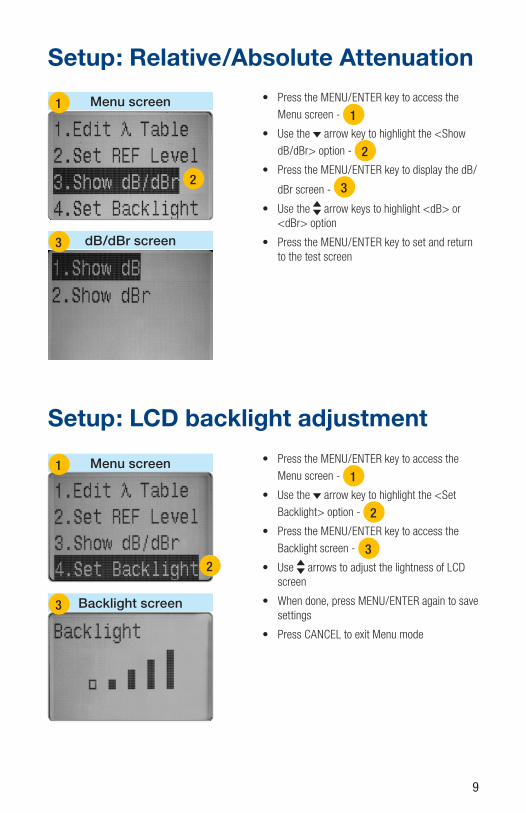
Application: Measuring Operating Limits
The VOA6-SM may be used to determine the operating limits of an optical transmission system. Operating limits are the minimum and maximum optical span loss values at which an optical system still meets its performance requirements.
1 Set VOA6-SM attenuation to the approximate mid-range optical span loss value for your optical system. For example if your system is designed to operate over optical spans with 10 to 50 dB of loss, set VOA6-SM attenuation to about 30 dB.
2 Connect the free end of jumper cable #1 to the output or your transmitter and the free end of jumper cable #2 to the input of your receiver.
3 Verify that your optical system is operating normally.
4 To measure maximum attenuation, increase VOA6-SM attenuation until your optical system fails to meet performance requirements. Then decrease attenuation until system performance just meets requirements. The attenuation value displayed by the VOA6-SM equals the maximum attenuation limit.
5 To measure minimum attenuation, decrease VOA6-SM attenuation to the minimum span loss specified by the optical system manufacturer (to prevent damage to your receiver, do not decrease attenuation below this value) or until your optical system fails to meet performance requirements. If necessary, increase attenuation until system performance just meets requirements. The attenuation value displayed by the VOA6-SM equals the minimum attenuation limit.
jumper cable #1
Transmitter
VOA6-SM
Receiver
jumper cable #2
13
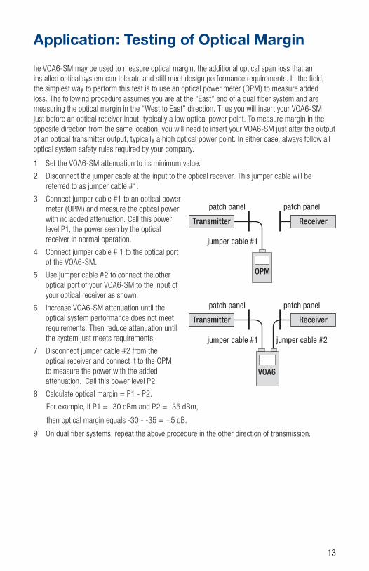
Application: Testing of Optical Margin
he VOA6-SM may be used to measure optical margin, the additional optical span loss that an installed optical system can tolerate and still meet design performance requirements. In the field, the simplest way to perform this test is to use an optical power meter (OPM) to measure added loss. The following procedure assumes you are at the “East” end of a dual fiber system and are measuring the optical margin in the “West to East” direction. Thus you will insert your VOA6-SM just before an optical receiver input, typically a low optical power point. To measure margin in the opposite direction from the same location, you will need to insert your VOA6-SM just after the output of an optical transmitter output, typically a high optical power point. In either case, always follow all optical system safety rules required by your company.
1 Set the VOA6-SM attenuation to its minimum value.
2 Disconnect the jumper cable at the input to the optical receiver. This jumper cable will be referred to as jumper cable #1.
3 Connect jumper cable #1 to an optical power meter (OPM) and measure the optical power with no added attenuation. Call this power level P1, the power seen by the optical receiver in normal operation.
4 Connect jumper cable # 1 to the optical port of the VOA6-SM.
5 Use jumper cable #2 to connect the other optical port of your VOA6-SM to the input of your optical receiver as shown.
6 Increase VOA6-SM attenuation until the optical system performance does not meet requirements. Then reduce attenuation until the system just meets requirements.
7 Disconnect jumper cable #2 from the optical receiver and connect it to the OPM to measure the power with the added attenuation. Call this power level P2.
8 Calculate optical margin = P1 - P2.
For example, if P1 = -30 dBm and P2 = -35 dBm,
then optical margin equals -30 - -35 = +5 dB.
9 On dual fiber systems, repeat the above procedure in the other direction of transmission.
jumper cable #1
Transmitter Receiver
OPM
patch panel patch panel
jumper cable #1
Transmitter Receiver
patch panel patch panel
VOA6
jumper cable #2

14
Cleaning TipsClean Test Cables and FUTIt is important to keep connector end-faces on the launch and receive cables and those on the Fiber Under Test (FUT) clean, to ensure accurate measurements and operation.
IMPORTANT! Inspect optical connectors after cleaning to ensure cleaning was successful and to verify the end-face is not damaged (cracked, pitted, etc.).
CAUTION! Never view a live fiber. Laser radiation is harmful to eyes.
Follow your company’s approved cleaning procedures.
AFL recommends cleaning test cables using a Cletop cassette cleaner or a One-Click Cleaner.
Cleaning the Optical PortsCAUTION! Before conducting the following procedures be sure to have the OTDR turned OFF.
Cleaning the Input/Output ports without removing the adapters
AFL One-Click Cleaner method
• Remove the protective dust cover from the tip of the One-Click Cleaner.
• Insert the tip of the One-Click Cleaner into the optical port adapter and gently press the body of the One-Click Cleaner until an audible “click” is heard.
• Remove the One-Click Cleaner.
AFL FCC2 fluid and CCT stick method
• Lean a can of FCC2 back (30°), press the button on FCC2 to fill the well.
• Dip a CCT stick into the well of the FCC2 to dampen the tip with optical cleaning fluid.
• Place the damp tip over the ferrule to be cleaned.
• Rotate the tip clockwise 10 revolutions while applying varying pressure to create a gentle
Recommended Accessories
The VOA6-SM comes with a protective rubber boot, AC adapter, Li-Ion battery, (2) thread-on FC connector adapters, universal power converter to allow international customers use the supplied USA style power adapters, and a soft carry case.
Recommended Accessories:
MODEL DESCRIPTION
2900-FT-LS-FC MR FC Connector
2900-FT-LS-SC MR SC Connector
2900-FT-LS-ST MR ST Connector
8500-05-0001MZ One-Click Cleaner SC/ST/FC
8500-10-0016MZ Cletop-SB
HiLite Visual fault identifier, 650 nm

15
pumping action where the tip contacts the ferrule.
• Discard the CCT stick after using both tips.
Cleaning the Input/Output ports with adapters removed
Removing connector adapters for cleaning and inspection
To access the Input/Output port
• Rotate the adapter base counterclockwise.
• Pull the adapter directly out away from the universal adapter mount to expose the ferrule.
Cleaning the Exposed Ferrule
Use lint-free optical cleaning wipes such as AFL FiberWipes and optical quality cleaning fluid such as AFL FCC2 connector cleaning fluid.
Note: if using isopropyl alcohol (IPA), be sure to use 99% pure IPA that has not been contaminated.
1 Dampen a portion of the wipe with the cleaning fluid.
2 Gently wipe the exposed ferrule (OPM port) starting with the wet section of the wipe and pulling it to the dry section.
– Note: Starting with the wet cleaning and finishing in the dry improves cleaning action, reduces static buildup, and finishes with the end-face dry.
Cleaning the adapters
Method 1:
1 Insert a Cletop adapter cleaning stick into the sleeve of the adapter and rotate 10 times.
2 Remove.
3 After cleaning the adapter, replace the adapter over the ferrule; centering it onto the alignment pin.
4 Tighten the adapter base.
Method 2:
1 Use a can of filtered compressed air (held vertically), blow out any contaminates from the adapter.
2 After cleaning the adapter, replace the adapter over the ferrule; centering it onto the alignment pin.
3 Tighten the adapter base.
16
Maintenance Tips • Keep using one type of adapter to avoid excess loss from different connectors
• Turn off the unit and cover dust proof cap after your test
• Use the power adapter within regulated voltage when using external power
• Take out the battery when it is not in use for a period of time
• Cover well the dust-proof cap when not in use
• To avoid serious damages, use the original charger to charge the battery
Recharging BatteryThe Li-Ion battery may be charged using a wall charger shipped with your VOA6-SM.
• Pull off the bottom of the VOA6-SM boot
• Open the battery compartment door and remove the battery
• Insert the discharged battery into the wall charger
• Plug the wall charger into a standard wall outlet
• Note how the [Charger] indicator on the wall charger front panel turns on [Red].
• Charge battery until the [Charger] indicator turns [Green].
Repair and CalibrationAFL suggests that NOYES test equipment be calibrated every 12 months by an authorized NOYES calibration facility.
Annual calibration ensures that you are getting the most out of your equipment and that it is performing accurately. Many test standards also require annual calibration.
Authorized NOYES calibration facilities are ISO 9001 certified, traceable to the National Institute of Standards and Technology, and in compliance with ANSI/NCSL Z540-1, ISO 10012-1.
Please contact customer service for a return authorization number prior to sending your NOYES test equipment in for repair or calibration.
USA Repair and Calibration services
NOYES Test and Inspection Division
16 Eastgate Park Road
Belmont, NH 03220
603-528-7780
800-321-5298
Europe Repair and Calibration services
Fujikura Europe Ltd.
C51 Barwell Business Park
Leatherhead Road
Chessington, Surrey, KT9 2NY
+44 (0) 208 240 2020
Fujikura Europe Ltd. is an Authorized European Repair and Calibration facility for NOYES Test and Inspection products from AFL and should be contacted directly for service.

17
Troubleshooting DESCRIPTION POSSIBLE REASON METHOD
No display after turning on the unit
Battery is weakFail to turn on the unit
Charge batteryTurn on the unit again
Wrong test result Dirty connector or bad connection
Clean the connector and re-connect the fiber
Contact UsYou may call NOYES Customer Service between 8 AM and 5 PM, United States Eastern Time.
Phone 800-321-5298
603-528-7780
Fax 603-528-2025
Mail [email protected]

Test and Inspection
Thank you for choosing NOYES Test and Inspection
CERTIFIED9001
ISONOYES FIBER SYSTEMS


![]]afl]admf - dhv.de · >dm?l=;@factd9f](https://img.pdfslide.us/doc/110x75/5ccb725388c993b16c8d573b/afladmf-dhvde-dmlfactd9f.jpg)