Embed Size (px)
Citation preview

VND101, Workshop 06 WS06-1
MSC.visualNastran 4D
Exercise Workbook
Four Bar Linkage

VND101, Workshop 06 WS06-2

VND101, Workshop 06 WS06-3
ObjectivesThis demonstration extends the user’s training in the creation of kinematic constraints. The specific category of constraints to be created here are the rotational constraints. This category of constraints includes rigid joints, revolute joints (Hinges), spherical joints and motors. These constraints share the feature that they constrain the attachment points of the two connected bodies to a common global position.
New Concepts Introduced• Definition of rotational Constraints
• Assembly Options in Creating Constraints
• Splitting and rejoining constraints
• Making force and torque measurements
Figure 1 Four Bar Linkage

VND101, Workshop 06 WS06-4
Exercise Overview1) Assemble the Four-Bar Linkage
2) Define Coords on Driving Link
3) Define Coords on Middle Link
4) Define Coords on Pivoting Link
5) Create Revolute Connections
6) Create Revolute Joint Between the Pivoting Link and the Middle Link
7) Create Revolute Joint Between the Pivoting Link and the Background
8) Create a Motor Connection Between Driving Link and the Background
9) Run Simulation
10) Hide Coords
11) Take Measurements
12) Take Measurement on the Force carried by the Constraint MDRevolute
13) Run Simulation with Meter
14) Increase Frame Display Rate Through Accuracy Dialogue

VND101, Workshop 06 WS06-5
I - Open Part File
1) Open the file “four bar.wm3”.
Figure 2 Open File

VND101, Workshop 06 WS06-6
II - Assigning the Three Links
The name Four-Bar Linkage implies that the mechanism consists of four bodies. It is composed of three moving links, and one fixed link that has connections to the moving links to make a closed loop. The figure on the first page of this tutorial shows the completed four bar linkage. The motion of this assembly is driven by a motor which connects the shortest of the three links to the background. Because of this, we refer to this shortest link as the Driving Link. Accordingly, the link in the middle is referred to as the Middle Link. Because the final link assumes a pivoting motion, very much like that of a windshield wiper, the final link is referred to as the Pivoting Link.
Middle Link
Ground Link
Driving Link
Pivoting Link
Figure 3 Parts

VND101, Workshop 06 WS06-7
III - Assemble the Four-Bar Linkage
Applying Coords
Driving Link
2) Pick the Coord tool from the Sketch Toolbar.
3) On the “Driving Link”, move the mouse over the left hole until a circle appears. (Figure 4)
It may be necessary to zoom in on the part.
The circle indicates that the coord will be placed in the middle of the circle the mouse is currently over.
4) Left-click the mouse once and observe that the coord is placed in the center of the circle.
Make sure the coord is placed so it is facing you. If the coord is not bright red or cannot be seen, it was placed on the other side. It must be deleted and replaced. To delete the coord, highlight the coord and click the “Delete” key.
5) Use the Rotate Around tool to rotate the Driving Link 180°. (Figure 5)
The backside of the Driving Link is now shown, so the red coord is no longer visible.
Figure 4 Driving Link
Figure 5 Backside of Objects

VND101, Workshop 06 WS06-8
6) Pick the Coord tool from the Sketch Toolbar.
7) Move the mouse over the left hole of the “Driving Link” until a circle appears as the curser.
8) Left-click the mouse once to place the coord in the center of the circle.
A red coord with a box around now appears in the center of the left hole of the “Driving Link”.
9) Hit “H” on the keyboard to return to the original view.
“H” stands for “Home” view. Clicking “H” will revert the simulation window back to the original, or “Home” view. In this example, the “Home” view is the front side of these links.
10) Double-click the left coord on the front of the “Driving Link” to open the “Properties” dialog box.
11) Under the Appearance tab, assign the name “DrivetoMotor”, and click the “Apply” button.
12) With the Appearance dialog box still open, select the other coord on the “Driving Link”.
This can be accomplished by rotating the Driving Link in the Simulation Window again or clicking the plus next to “Driving Link” from the Object Manager List (Figure 7).
13) Assign the name “DrivingtoMDRevolute”, and click “Close”.
Now, if you open the “Driving Link” tree in the Object Browser window, you will see the new names just assigned to the two coords.
Figure 6 Appearance Tab of Coord
III - Assemble the Four-Bar Linkage
Figure 7 Object Manager List

VND101, Workshop 06 WS06-9
Middle Link
14) Pick the Coord tool from the Sketch Toolbar.The curser changes to a coord.
15) On the “Middle Link”, move the mouse over the right hole until a circle appears. Left-click the mouse once.
You can find the “Middle Link” by highlighting it first in the Object Browser window or look at Figure 8. Again, if the coord is not bright red and not visible, it must be deleted and replaced.
16) Repeat the last two steps to place a coord in the middle of the left circle of the “Middle Link”. (Figure 8)
17) Double-click the right coord to open the “Properties” dialog box.
You can run the mouse over the two coords in the Object Browser (found under the “Middle Link” tree) and a dotted box will appear around the corresponding coord in the simulation window.
18) Under the Appearance tab, assign the name “MiddletoMDRevolute”, and click “Apply”.
18) With the Appearance tab still open, select the left coord on the “Middle Link”.
19) Assign the name “MiddletoMPRevolute” and close the “Properties” Menu. (Figure 9)
Figure 9 MiddletoMPRevolute
III - Assemble the Four-Bar Linkage
Figure 8 Middle Link

VND101, Workshop 06 WS06-10
Pivoting Link
21) Pick the Coord tool from the Sketch Toolbar.
22) On the “Pivoting Link”, move the mouse over the bottom hole until a circle appears.
The “Pivoting Link” can be found by highlighting it once in the Object Browser window.
23) Left-click the mouse once.
Make sure the coord is facing you.
24) Rotate the “Pivoting Link” 180° using the Rotate Around tool. (Figure 10)
If you rotate the window and the “Pivoting Link” moves out of the window, hit the “V” key to put all the bodies into “View”.
Notice that the coord placed on the bottom of the “Pivoting Link” is visible. This is because the Pivoting Link is translucent.
25) Repeat the steps 21 and 22 to place a coord in the middle of the top circle of the Pivoting Link. (Figure 10)
III - Assemble the Four-Bar Linkage
Figure 10 Backside of Pivoting Link

VND101, Workshop 06 WS06-11
25) Press “H” on the keyboard to return to the original view.
The bodies on the simulation window flip around 180 degrees.
26) Double-click the bottom coord on the “Pivoting Link” to open the “Properties” dialog box.
27) Under the Appearance tab, assign the name “PivotingtoGround”, and click “Apply”. (Figure 11)
28) With the Appearance tab still open, select the top coord on the Pivoting Link.
Find it either by rotating the Simulation Window or under the “Pivoting Link” tree in the Object Browser.
29) Assign the name “PivotingtoMPRevolute”, and close the “Properties” Menu. (Figure 12)
III - Assemble the Four-Bar Linkage
Figure 11 Bottom Coord
Figure 12 Top Coord
VND101, Workshop 06 WS06-12
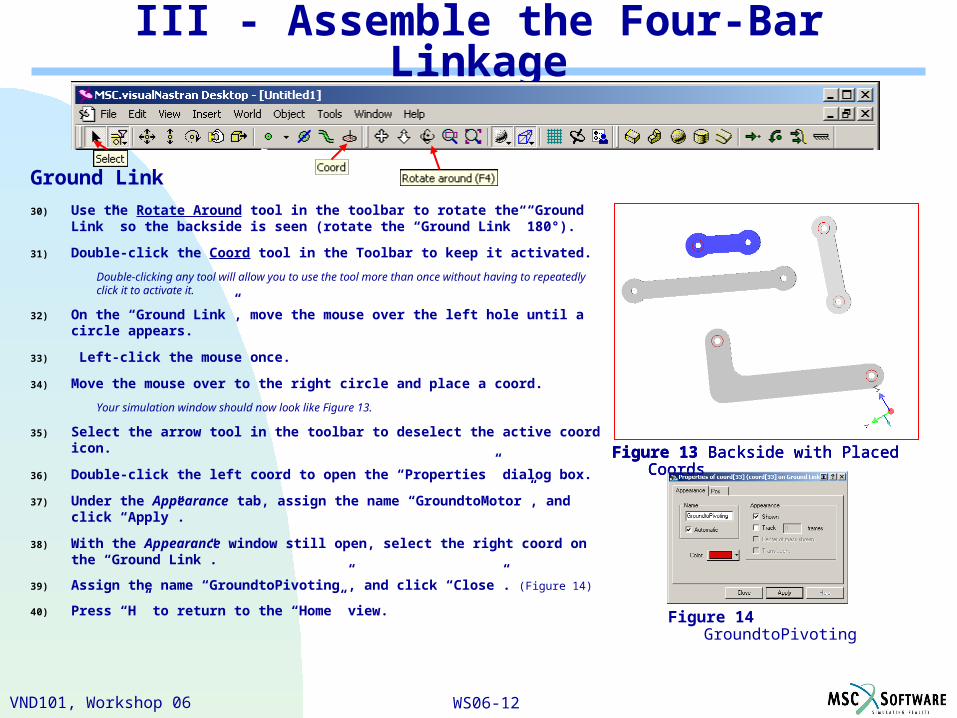
Ground Link
30) Use the Rotate Around tool in the toolbar to rotate the “Ground Link” so the backside is seen (rotate the “Ground Link” 180°).
31) Double-click the Coord tool in the Toolbar to keep it activated.
Double-clicking any tool will allow you to use the tool more than once without having to repeatedly click it to activate it.
32) On the “Ground Link”, move the mouse over the left hole until a circle appears.
33) Left-click the mouse once.
34) Move the mouse over to the right circle and place a coord.
Your simulation window should now look like Figure 13.
35) Select the arrow tool in the toolbar to deselect the active coord icon.
36) Double-click the left coord to open the “Properties” dialog box.
37) Under the Appearance tab, assign the name “GroundtoMotor”, and click “Apply”.
38) With the Appearance window still open, select the right coord on the “Ground Link”.
39) Assign the name “GroundtoPivoting”, and click “Close”. (Figure 14)
40) Press “H” to return to the “Home” view.
III - Assemble the Four-Bar Linkage
Figure 13 Backside with Placed CoordsFigure 13 Backside with Placed CoordsFigure 13 Backside with Placed Coords
Figure 14 GroundtoPivoting

VND101, Workshop 06 WS06-13
IV - Constraining the Linkage
Adding Constraints
40) Click on all the pluses in the Object Browser to open all the trees, exposing all the coords created.
41) Select the “DrivetoMotor” coord on the “Driving Link”. Then hold down the “Shift” key and select the “GroundtoMotor” coord on the “Ground Link”.
The Rotate Around tool can be used to select coords that may difficult. An easier way is to select these coords is using the “Control” key in the Object Manager. (Figure 15)
42) Click the Create Constraint tool from the toolbar.
41) Scroll down and pick “Revolute Motor” as the type of constraint and constrain the two joints using “Face-To-Face”. (Figure 16)
42) Click “Create” to create the constraint.
The “Driving Link” is moved to the “Ground Link”, since we chose “GroundtoMotor” to be our base coord by choosing it second. Referring to Figure 16, the “DrivietoMotor” on the “Driving Link” is moved to the “Ground to Motor” of the “Ground Link”.
A green icon appears in the hole connecting the “Driving Link” and the “Ground Link”.
43) Double-click the “Revolute Motor” that was just created, either in the Object Browser List or the Workspace, to open the “Properties” dialog box.
Figure 15 Object Browser
Figure 16 Create Constraint Menu for GroundtoMotor Coord

VND101, Workshop 06 WS06-14
45) Click the left or right arrow to scroll to the Appearance tab.
46) Assign the name “Motor” for this constraint and click “Apply”.
47) Click the left or right arrow to scroll to the Motor tab.
48) Under “Motor Type”, pick “Torque”. (Figure 17)
49) Enter “11 lbf in” in the “Value” field, indicating the amount of Torque, and click “Close” to close the “Properties” dialog box. (Figure 17)
50) In the Object Browser, select the “MiddletoMDRevolute” coord on the “Middle Link”. Then hold down the “Control” key and select the “DrivingtoMDRevolute” coord on the “Driving Link”.
51) Pick the Create Constraint tool from the toolbar.
52) Choose “Revolute Joint” as the type of constraint.
53) Pick the “Face-To-Face” assembly option.
This moves “Middle Link” and flips the “MiddletoMDRevolute”.
54) Click “Create” to create the constraint.
There is now a revolute joint connecting the “Middle Link” to the “Driving Link”.
IV - Constraining the Linkage
Figure 17 Motor Tab
Figure 18 Create Constraint menu for DrivingtoMDRevolute coord

VND101, Workshop 06 WS06-15
55) Double-click this constraint in the Connections window to open the “Properties” dialog box. (Figure 19)
This revolute joint looks like a green round joint. (Figure 19)
56) Under the Appearance tab, assign the name “MDRevolute” to the constraint and close the Properties window.
57) In the Object Browser, select the “PivotingtoGround” coord on the “Pivoting Link”. Hold down the “Control key and select the GroundtoPivoting coord on the Ground Link.
58) Pick the Create Constraint tool from the toolbar.
59) Pick “Revolute Joint” and “Face-To-Face”. (Figure 20)
60) Click “Create” to create the constraint.
The “Pivoting Link” is now connected to the “Ground Link”.
IV - Constraining the Linkage
Figure 20 Create Constraint Menu for GroundtoPivoting Coord
Figure 19 Connections window

VND101, Workshop 06 WS06-16
61) In the Object Browser, select the “MiddletoMPRevolute” coord on the “Middle Link”. Hold down the “Control” key and select the “PivotingtoMPRevolute” coord on the “Pivoting Link”.
62) Pick “Create Constraint” from the constraint toolbar.
63) Pick “Revolute Joint” as type of constraint.
64) Click the “Face-To-Face” assembly option.
65) Click “Create” to create the constraint.
The simulation window should now look like Figure 21.
66) Right-click the mouse on the “Ground Link” and scroll to Fixed to fix the ground link to the background. (Figure 22)
Now, if you look over to the connection’s window or object browser, the ground link” icon has an anchor on it, representing that it’s fixed to the ground.
Figure 21 Assembled Four-Bar Linkage
IV - Constraining the Linkage
Figure 22 Fixed
VND101, Workshop 06 WS06-17
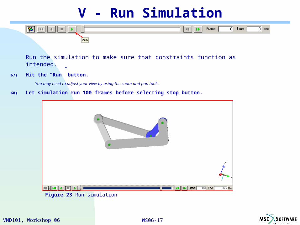
V - Run Simulation
Run the simulation to make sure that constraints function as intended.
67) Hit the “Run” button.
You may need to adjust your view by using the zoom and pan tools.
68) Let simulation run 100 frames before selecting stop button.
Figure 23 Run simulation
VND101, Workshop 06 WS06-18
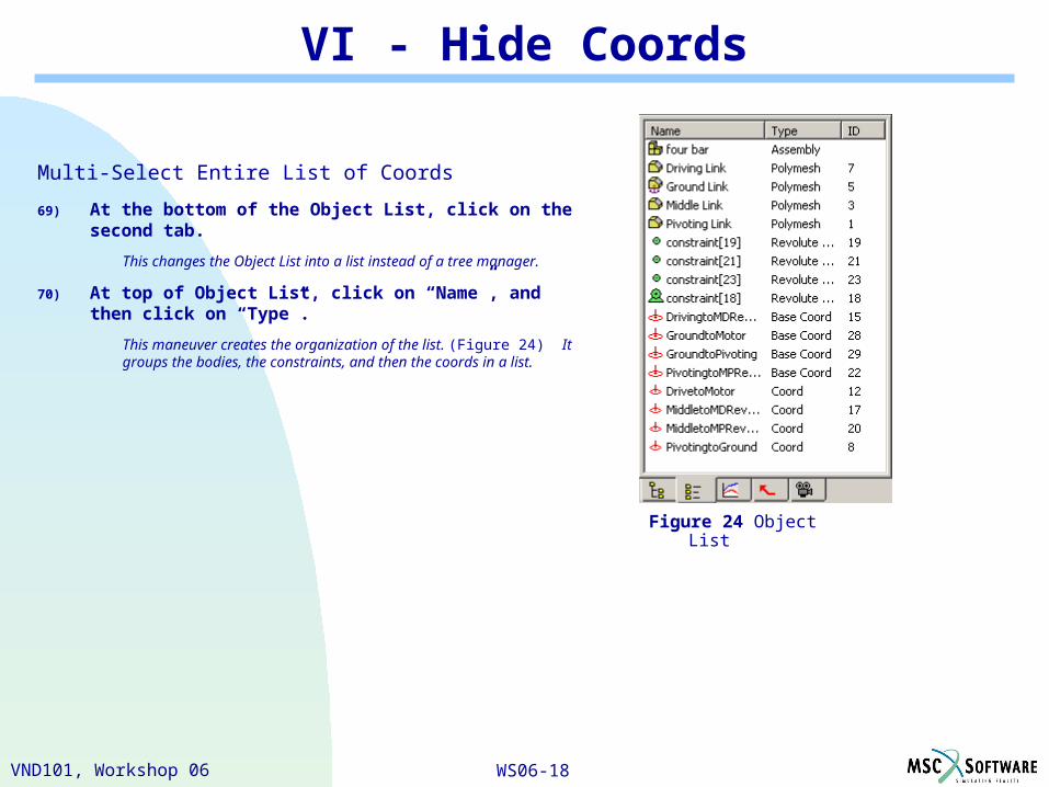
VI - Hide Coords
Multi-Select Entire List of Coords
69) At the bottom of the Object List, click on the second tab.
This changes the Object List into a list instead of a tree manager.
70) At top of Object List, click on “Name”, and then click on “Type”.
This maneuver creates the organization of the list. (Figure 24) It groups the bodies, the constraints, and then the coords in a list.
Figure 24 Object List

VND101, Workshop 06 WS06-19
VI - Hide Coords
71) Scroll down the list so you can see the whole coord list.
With this arrangement, the coord “DrivingtoMDRevolute” should appear at the top of the list of coords.
72) Select “DrivingtoMDRevolute”.
73) Holding the shift key down, select “PivotingToGround”, which should appear at the bottom of the list of coords.
With this selection, the entire list of coords should be selected. (Figure 25)
73) Locate the mouse anywhere over the highlighted list, right click, and in the list of options that drops down, pick Hide. (Figure 26)
The coords will disappear from the workspace. Also, it may be hard to tell, but coord icons in the connections window or object list will be faded. Figure 25 Selected coords
Figure 26 Hide coords

VND101, Workshop 06 WS06-20
VII - Take Measurements
Take Measurements on the Torque Exerted by the Motor
74) In the Object List window, click the “Motor” once to highlight it.
The motor will be highlighted by a green square in the simulation window.
75) Pull down the Insert menu and pick Meter>Constraint Torque.
76) Pick “Driving Link” in the first box, “GroundToMotor” in the second box, and then click “OK”. (Figure 27)
77) Accept “Tile Vertically” in the Tiling Options window.
The torque measurement is made relative to the coordinate system GroundToMotor. Because the constraint applies a torque equal in magnitude but opposite in sign to each of the two body’s connected by the constraint, MSC.visualNastran Desktop 4D must inform us to which body the measured torque applies. As indicated in the window, the torque applies to the Driving Link.
Figure 27 Torque Meter on Motor

VND101, Workshop 06 WS06-21
VIII - Take Measurement on the Force carried by the Constraint MDRevolute
78) Select the constraint, “MDRevolute”.
79) Insert a “Meter” measuring “Constraint Force” on “Driving Link” expressed in “MiddleToMDRevolute”. (Figure 28)
80) Accept to “Tile Vertically”.
Your simulation window should now have 2 meters below it. (Figure 29)
Figure 28 Force Meter on MDRevolute
Figure 29 Meters

VND101, Workshop 06 WS06-22
IX - Run Simulation with Meter
81) Hit the “Run” button.
82) Let simulation run for 50 frames before stopping.
Measurements appear choppy. (Figure 31)
Figure 31 Run simulation with force meters

VND101, Workshop 06 WS06-23
X - Frame Display Rate Through Accuracy Dialogue
83) Pull down the World menu and pick Simulation Settings.
Pick the Integration tab. Figure 32 shows the dialogue that appears.
84) Modify animation step by displaying frames at a rate of 500 / sec.
Notice that all of the other fields update to the change.
Figure 32 Simulation Settings - Integration
VND101, Workshop 06 WS06-24
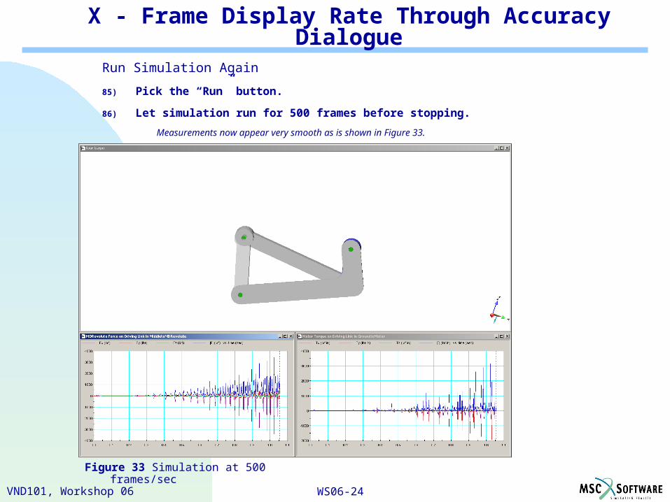
Run Simulation Again
85) Pick the “Run” button.
86) Let simulation run for 500 frames before stopping.
Measurements now appear very smooth as is shown in Figure 33.
Figure 33 Simulation at 500 frames/sec
X - Frame Display Rate Through Accuracy Dialogue