Embed Size (px)
Citation preview
WS15-1VND101, Workshop 15
MSC.visualNastran 4D
Exercise Workbook
Analysis of an Oven Tab: Thermal Simulation in 4D

WS15-2VND101, Workshop 15
WS15-3VND101, Workshop 15
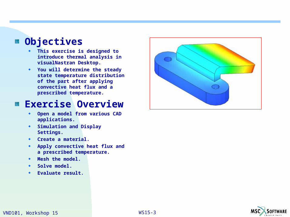
ObjectivesThis exercise is designed to introduce thermal analysis in visualNastran Desktop.
You will determine the steady state temperature distribution of the part after applying convective heat flux and a prescribed temperature.
Exercise OverviewOpen a model from various CAD applications.
Simulation and Display Settings.
Create a material.
Apply convective heat flux and a prescribed temperature.
Mesh the model.
Solve model.
Evaluate result.
WS15-4VND101, Workshop 15
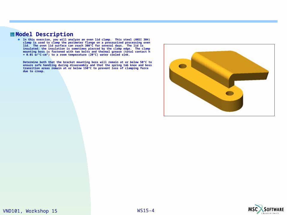
Model DescriptionIn this exercise, you will analyze an oven lid clamp. This steel (ANSI 304) clamp is used to clamp the perimeter flange on a pressurized processing oven lid. The oven lid surface can reach 300°C for several days. The lid is insulated; the insulation is sometimes pierced by the clamp edge. The clamp mounting boss is fastened with two bolts and thermal grease (total contact h = 0.01 w/°C-cm²) to a room temperature (20°C) water cooled sink.
Determine both that the bracket mounting boss will remain at or below 50°C to ensure safe handling during disassembly and that the spring tab knee and boss transition areas remain at or below 150°C to prevent loss of clamping force due to creep.
WS15-5VND101, Workshop 15
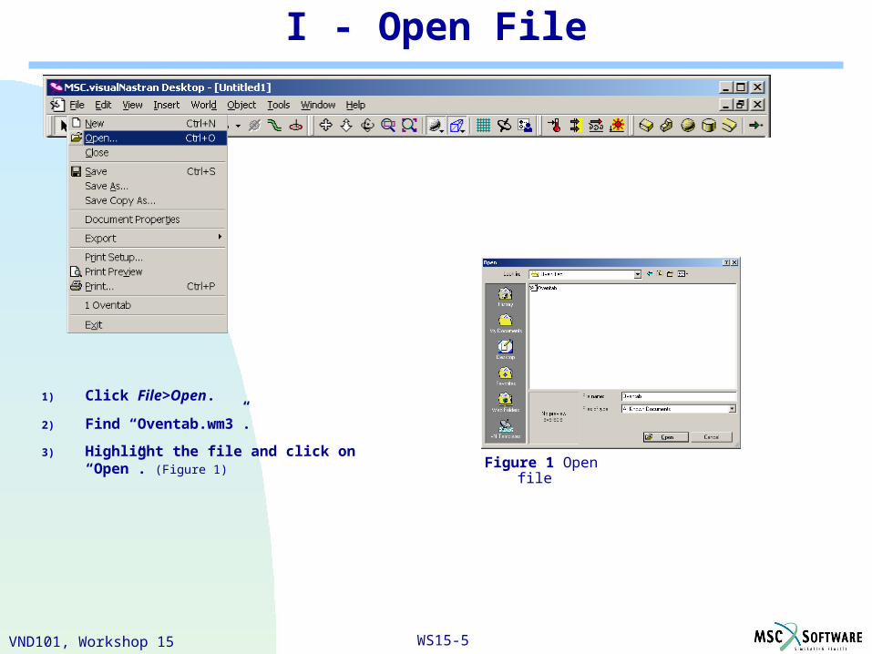
I - Open File
1) Click File>Open.
2) Find “Oventab.wm3”.
3) Highlight the file and click on “Open”. (Figure 1)Figure 1 Open file
WS15-6VND101, Workshop 15
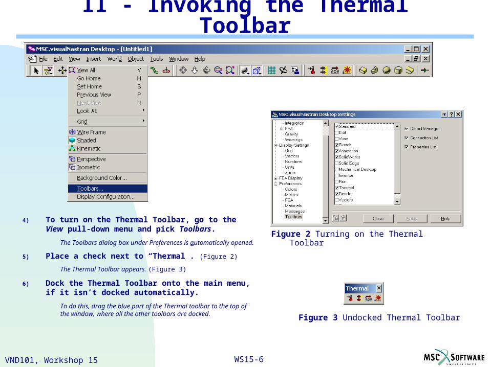
II - Invoking the Thermal Toolbar
4) To turn on the Thermal Toolbar, go to the View pull-down menu and pick Toolbars.
The Toolbars dialog box under Preferences is automatically opened.
5) Place a check next to “Thermal”. (Figure 2)
The Thermal Toolbar appears. (Figure 3)
6) Dock the Thermal Toolbar onto the main menu, if it isn’t docked automatically.
To do this, drag the blue part of the Thermal toolbar to the top of the window, where all the other toolbars are docked.
Figure 2 Turning on the Thermal Toolbar
Figure 3 Undocked Thermal Toolbar
WS15-7VND101, Workshop 15
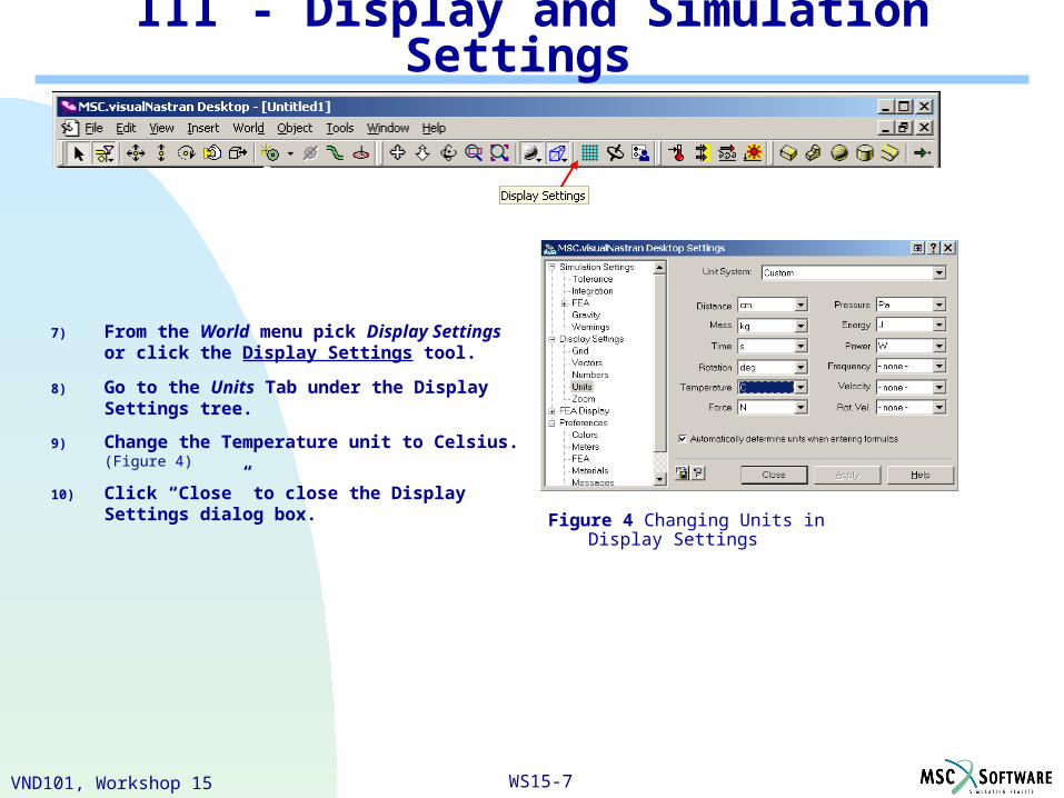
III - Display and Simulation Settings
Figure 4 Changing Units in Display Settings
7) From the World menu pick Display Settings or click the Display Settings tool.
8) Go to the Units Tab under the Display Settings tree.
9) Change the Temperature unit to Celsius. (Figure 4)
10) Click “Close” to close the Display Settings dialog box.
WS15-8VND101, Workshop 15
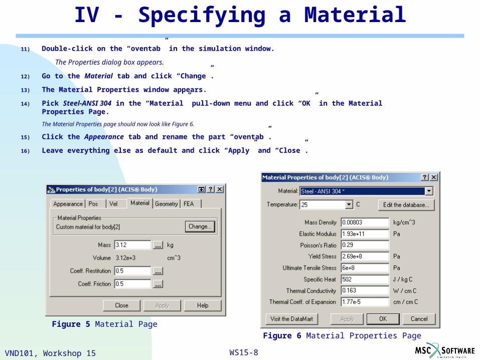
IV - Specifying a Material11) Double-click on the “oventab” in the simulation window.
The Properties dialog box appears.
12) Go to the Material tab and click “Change”.
13) The Material Properties window appears.
14) Pick Steel-ANSI 304 in the “Material” pull-down menu and click “OK” in the Material Properties Page.
The Material Properties page should now look like Figure 6.
15) Click the Appearance tab and rename the part “oventab”.
16) Leave everything else as default and click “Apply” and “Close”.
Figure 5 Material Page
Figure 6 Material Properties Page
WS15-9VND101, Workshop 15
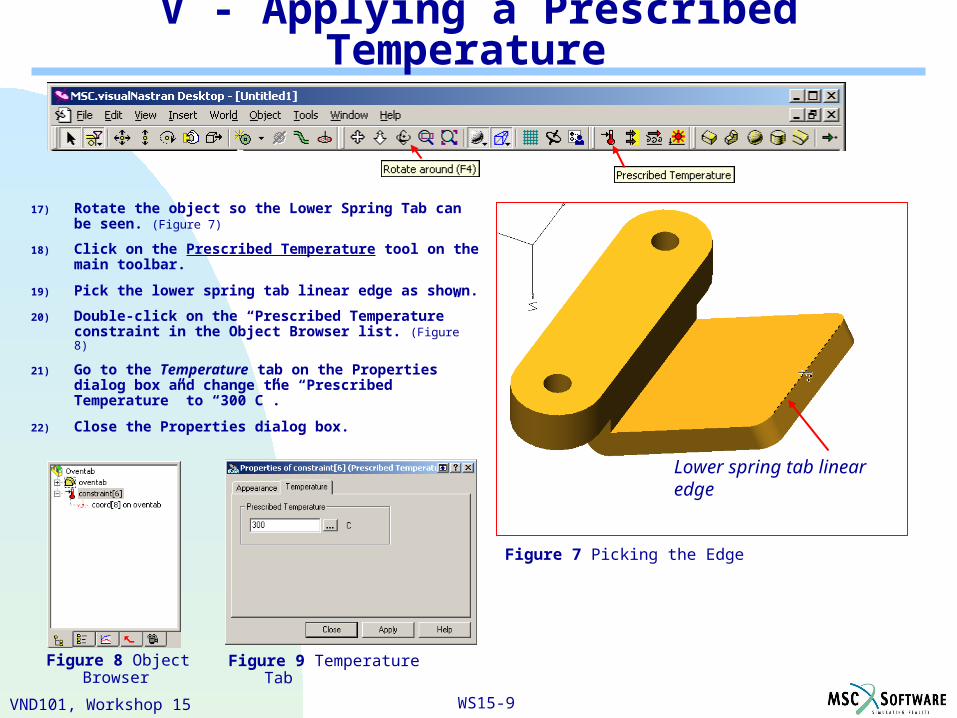
V - Applying a Prescribed Temperature
17) Rotate the object so the Lower Spring Tab can be seen. (Figure 7)
18) Click on the Prescribed Temperature tool on the main toolbar.
19) Pick the lower spring tab linear edge as shown.
20) Double-click on the “Prescribed Temperature” constraint in the Object Browser list. (Figure 8)
21) Go to the Temperature tab on the Properties dialog box and change the “Prescribed Temperature” to “300 C”.
22) Close the Properties dialog box.
Figure 7 Picking the Edge
Lower spring tab linear edge
Figure 9 Temperature TabFigure 8 Object Browser
WS15-10VND101, Workshop 15
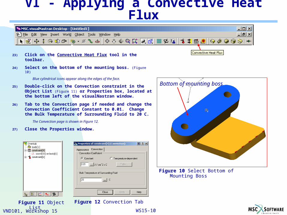
VI - Applying a Convective Heat Flux
23) Click on the Convective Heat Flux tool in the toolbar.
24) Select on the bottom of the mounting boss. (Figure 10)
Blue cylindrical icons appear along the edges of the face.
25) Double-click on the Convection constraint in the Object List (Figure 11) or Properties box, located at the bottom left of the visualNastran window.
26) Tab to the Convection page if needed and change the Convection Coefficient Constant to 0.01. Change the Bulk Temperature of Surrounding Fluid to 20 C.
The Convection page is shown in Figure 12.
27) Close the Properties window.
Figure 10 Select Bottom of Mounting Boss
Figure 12 Convection Tab
Bottom of mounting boss
Figure 11 Object List
WS15-11VND101, Workshop 15
VII - Solve Thermal FEA
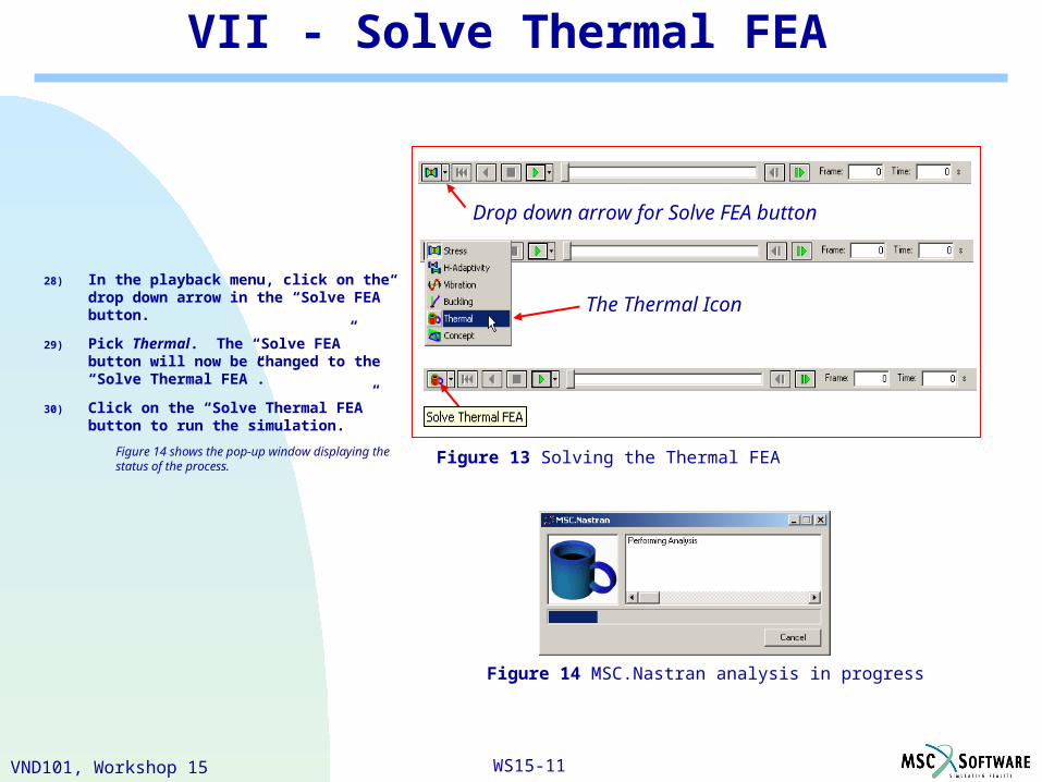
28) In the playback menu, click on the drop down arrow in the “Solve FEA” button.
29) Pick Thermal. The “Solve FEA” button will now be changed to the “Solve Thermal FEA”.
30) Click on the “Solve Thermal FEA” button to run the simulation.
Figure 14 shows the pop-up window displaying the status of the process. Figure 13 Solving the Thermal FEA
Drop down arrow for Solve FEA button
The Thermal Icon
Figure 14 MSC.Nastran analysis in progress
WS15-12VND101, Workshop 15
VIII - Results
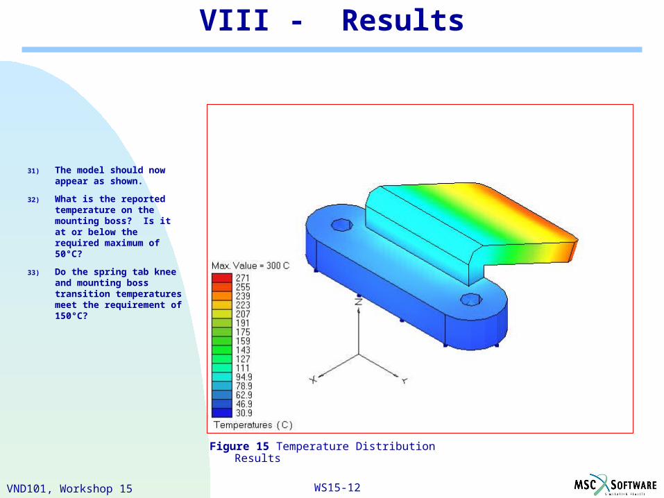
Figure 15 Temperature Distribution Results
31) The model should now appear as shown.
32) What is the reported temperature on the mounting boss? Is it at or below the required maximum of 50°C?
33) Do the spring tab knee and mounting boss transition temperatures meet the requirement of 150°C?
WS15-13VND101, Workshop 15
Review
You learned how to invoke the Thermal Toolbar.
You learned how to apply a Prescribed Temperature and a Convective Heat Flux.
You have also learned how to submit a Thermal Analysis.

WS15-14VND101, Workshop 15