Embed Size (px)
Citation preview
VMware Validated Design™ Operational Verification Guide
VMware Validated Design for Software-Defined Data Center 3.0
This document supports the version of each product listed and supports all subsequent versions until the document is replaced by a new edition. To check for more recent editions of this document, see http://www.vmware.com/support/pubs.
EN-002300-00
VMware Validated Design Operational Verification Guide
© 2016 VMware, Inc. All rights reserved.
Page 2 of 112
You can find the most up-to-date technical documentation on the VMware Web site at:
http://www.vmware.com/support/
The VMware Web site also provides the latest product updates.
If you have comments about this documentation, submit your feedback to: [email protected]
© 2016 VMware, Inc. All rights reserved. This product is protected by U.S. and international copyright and intellectual property laws. This product is covered by one or more patents listed at http://www.vmware.com/download/patents.html.
VMware is a registered trademark or trademark of VMware, Inc. in the United States and/or other jurisdictions. All other marks and names mentioned herein may be trademarks of their respective companies.
VMware, Inc.
3401 Hillview Avenue
Palo Alto, CA 94304
www.vmware.com
VMware Validated Design Operational Verification Guide
© 2016 VMware, Inc. All rights reserved.
Page 3 of 112
Contents
1. Purpose and Intended Audience ...................................................... 5
2. Validate Platform Services Controller and vCenter Server Instances ................................................................................................ 6
2.1 Verify the Platform Services Controllers ........................................................................ 6
2.2 Verify the vCenter Server Instances ............................................................................ 10
3. Validate the Cloud Management Platform ...................................... 16
3.1 Verify the Power Status and Address of All vRealize Automation, vRealize Orchestrator and vRealize Business VMs ................................................................................................. 16
3.2 Verify the Version, Service Status and Configuration of vRealize Automation Appliances 18
3.3 Verify the Status of IaaS Web Server and Manager Service Nodes of vRealize Automation 21
3.4 Verify the Version and Service Status of vRealize Automation Windows Nodes ........ 23
3.5 Verify the Version, Status and Configuration of the vRealize Orchestrator VMs ........ 28
3.6 Verify the Status of the Distributed Execution Managers and vSphere Proxy Agents in vRealize Automation ............................................................................................................ 36
3.7 Verify the Status of vRealize Automation Integration with Active Directory ................ 38
3.8 Verify the Version, Service Status and Configuration of the vRealize Business VMs . 39
3.9 Request a Single-Machine Blueprint from the Service Catalog of vRealize Automation47
3.10 Verify the Cloud Management Platform Load Balancing ............................................. 49
4. Validate NSX for vSphere .............................................................. 52
4.1 Verify the Version, Service Status and Configuration of the NSX Manager Appliances52
4.2 Verify the Status of NSX Controller Instances and Host Components ........................ 57
4.3 (Optional) Test VXLAN Connectivity of the Hosts in the Management Cluster ........... 60
4.4 (Optional) Test VXLAN Connectivity of the Hosts in the Shared Edge and Compute Cluster 63
4.5 Verify the Status of NSX Firewall, Service Composer and Distributed Switches ........ 66
4.6 Verify the Status of the NSX Edge Devices for North-South Routing .......................... 69
4.7 Verify the Status of the Universal Distributed Logical Router ...................................... 75
4.8 Verify the Status of the NSX Load Balancer ................................................................ 78
5. Validate vRealize Operations Manager .......................................... 84
5.1 Verify the Power Status of All vRealize Operations Manager VMs ............................. 84
5.2 Verify the Configuration of vRealize Operations Manager Cluster Nodes and Remote Collectors.............................................................................................................................. 85
5.3 Verify the vRealize Operations Manager Load Balancing ........................................... 88
5.4 Validate vRealize Operations Manager Adapters and Management Packs ................ 90
VMware Validated Design Operational Verification Guide
© 2016 VMware, Inc. All rights reserved.
Page 4 of 112
5.4.1 Verify the Version, Status and Configuration of the VMware vSphere Adapter in vRealize Operations Manager ............................................................................................................................ 91
5.4.2 Verify the Version and Configuration of the vRealize Operations Management Pack for Log Insight 92
5.4.3 Verify the Version, Status and Configuration of vRealize Operations Manager Management Pack for NSX for vSphere .................................................................................................................... 93
5.4.4 Verify the Version, Status and Configuration of the vRealize Automation Management Pack 96
5.4.5 Verify the Version, Status and Configuration of the Management Pack for Storage Devices in vRealize Operations Manager .............................................................................................................. 98
6. Validate vRealize Log Insight ....................................................... 101
6.1 Verify the Status of the vRealize Log Insight Nodes .................................................. 101
7. SDDC Startup and Shutdown....................................................... 108
7.1 Shutdown Order of the Management VMs ................................................................ 108
7.2 Startup Order of the Management VMs ..................................................................... 110
VMware Validated Design Operational Verification Guide
© 2016 VMware, Inc. All rights reserved.
Page 5 of 112
1. Purpose and Intended Audience
VMware Validated Design Operational Verification Guide provides step-by-step instructions for verifying that the management components in the Software-Defined Data Center (SDDC) are operating as expected.
After performing a maintenance operation of the management components in the software-defined data center (SDDC), verifying whether these components are running without any faults ensures continuous operation of the environment. Verify the operation of the SDDC after patching, updating, upgrading, restoring and recovering the SDDC management components.
Note The VMware Validated Design Operational Verification Guide is compliant and validated with certain product versions. See VMware Validated Design Release Notes for more information about supported product versions.
VMware Validated Design Operational Verification Guide is intended for cloud architects, infrastructure administrators, cloud administrators and cloud operators who are familiar with and want to use VMware software to deploy in a short time and manage an SDDC that meets the requirements for capacity, scalability, backup and restore, and extensibility for disaster recovery support.
VMware Validated Design Operational Verification Guide
© 2016 VMware, Inc. All rights reserved.
Page 6 of 112
2. Validate Platform Services Controller and vCenter Server Instances
After you perform maintenance in your environment, verify the version, service status and the configuration of each Platform Services Controller and vCenter Server Appliance instances.
Verify the Platform Services Controller Instances
Verify the vCenter Server Instances
2.1 Verify the Platform Services Controllers Validate the functionality of the Platform Services Controller for the Management vCenter Server and
of the Platform Services Controller for the Compute vCenter Server in Region A and Region B.
Start with the Platform Services Controller for the management cluster in Region A.
Table 1. Platform Services Controller Instances in the Environment
Region Platform Services Controller
FQDN VAMI URL PSC URL
Region A
Management Cluster
mgmt01psc01.sfo01.rainpole.local
https://fqdn:5480 https://fqdn/psc
Shared edge and compute
comp01psc01.sfo01.rainpole.local
https://fqdn:5480 https://fqdn/psc
Region B
Management Cluster
mgmt01psc51.lax01.rainpole.local
https://fqdn:5480 https://fqdn/psc
Shared edge and compute
comp01psc51.lax01.rainpole.local
https://fqdn:5480 https://fqdn/psc
Procedure
Log in to the management interface of the Platform Services Controller virtual appliance.
a. Open a Web browser and go to
https://mgmt01psc01.sfo01.rainpole.local:5480.
b. Log in using the following credentials.
Setting Value
User Name root
Password mgmtpsc_admin_password
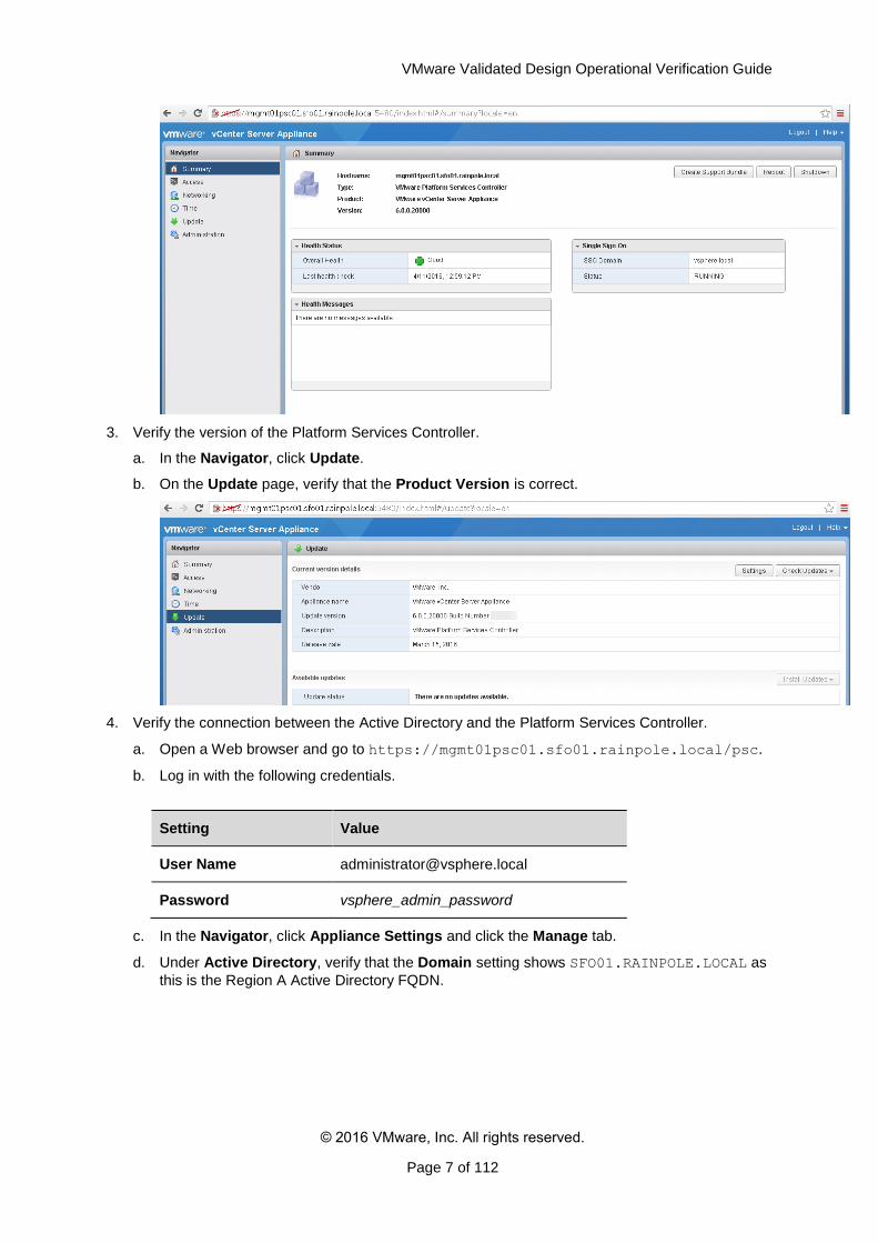
2. Verify the Health Status and the Single Sign-On status for this Platform Services Controller.
a. On the Summary page, under Health Status, verify that the Overall Health is Good.
b. Verify that the Single Sign-On status is RUNNING.
VMware Validated Design Operational Verification Guide
© 2016 VMware, Inc. All rights reserved.
Page 7 of 112
3. Verify the version of the Platform Services Controller.
a. In the Navigator, click Update.
b. On the Update page, verify that the Product Version is correct.
4. Verify the connection between the Active Directory and the Platform Services Controller.
a. Open a Web browser and go to https://mgmt01psc01.sfo01.rainpole.local/psc.
b. Log in with the following credentials.
Setting Value
User Name [email protected]
Password vsphere_admin_password
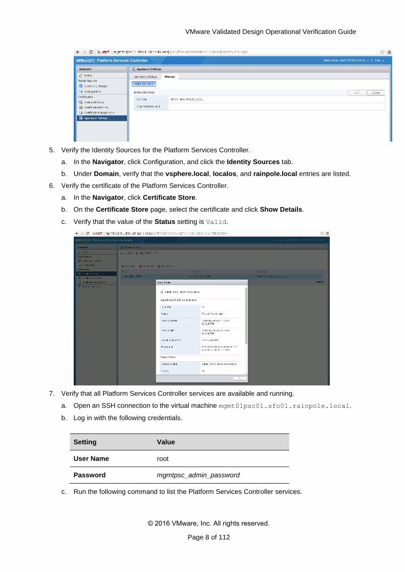
c. In the Navigator, click Appliance Settings and click the Manage tab.
d. Under Active Directory, verify that the Domain setting shows SFO01.RAINPOLE.LOCAL as
this is the Region A Active Directory FQDN.
VMware Validated Design Operational Verification Guide
© 2016 VMware, Inc. All rights reserved.
Page 8 of 112
5. Verify the Identity Sources for the Platform Services Controller.
a. In the Navigator, click Configuration, and click the Identity Sources tab.
b. Under Domain, verify that the vsphere.local, localos, and rainpole.local entries are listed.
6. Verify the certificate of the Platform Services Controller.
a. In the Navigator, click Certificate Store.
b. On the Certificate Store page, select the certificate and click Show Details.
c. Verify that the value of the Status setting is Valid.
7. Verify that all Platform Services Controller services are available and running.
a. Open an SSH connection to the virtual machine mgmt01psc01.sfo01.rainpole.local.
b. Log in with the following credentials.
Setting Value
User Name root
Password mgmtpsc_admin_password
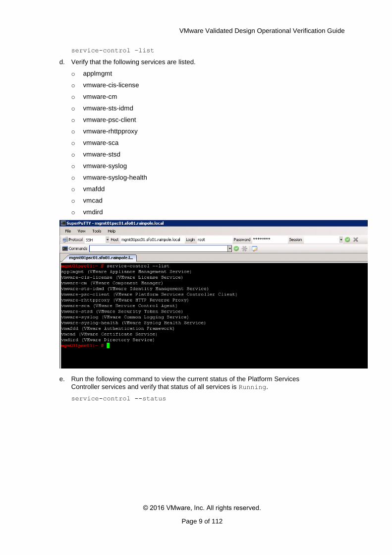
c. Run the following command to list the Platform Services Controller services.
VMware Validated Design Operational Verification Guide
© 2016 VMware, Inc. All rights reserved.
Page 9 of 112
service-control –list
d. Verify that the following services are listed.
o applmgmt
o vmware-cis-license
o vmware-cm
o vmware-sts-idmd
o vmware-psc-client
o vmware-rhttpproxy
o vmware-sca
o vmware-stsd
o vmware-syslog
o vmware-syslog-health
o vmafdd
o vmcad
o vmdird
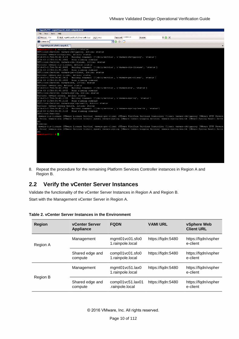
e. Run the following command to view the current status of the Platform Services
Controller services and verify that status of all services is Running.
service-control --status
VMware Validated Design Operational Verification Guide
© 2016 VMware, Inc. All rights reserved.
Page 10 of 112
8. Repeat the procedure for the remaining Platform Services Controller instances in Region A and Region B.
2.2 Verify the vCenter Server Instances
Validate the functionality of the vCenter Server Instances in Region A and Region B.
Start with the Management vCenter Server in Region A.
Table 2. vCenter Server Instances in the Environment
Region vCenter Server Appliance
FQDN VAMI URL vSphere Web Client URL
Region A
Management mgmt01vc01.sfo01.rainpole.local
https://fqdn:5480 https://fqdn/vsphere-client
Shared edge and compute
comp01vc01.sfo01.rainpole.local
https://fqdn:5480 https://fqdn/vsphere-client
Region B
Management mgmt01vc51.lax01.rainpole.local
https://fqdn:5480 https://fqdn/vsphere-client
Shared edge and compute
comp01vc51.lax01.rainpole.local
https://fqdn:5480 https://fqdn/vsphere-client
VMware Validated Design Operational Verification Guide
© 2016 VMware, Inc. All rights reserved.
Page 11 of 112
Procedure
Log in to the management interface of the Management vCenter Server to verify the access to the appliance.
a. Open a Web browser and go to
https://mgmt01vc01.sfo01.rainpole.local:5480.
b. Log in using the following credentials.
Setting Value
User Name root
Password mgmtvc_admin_password
On the Summary page, under Health Status, verify that the Overall Health is Good.
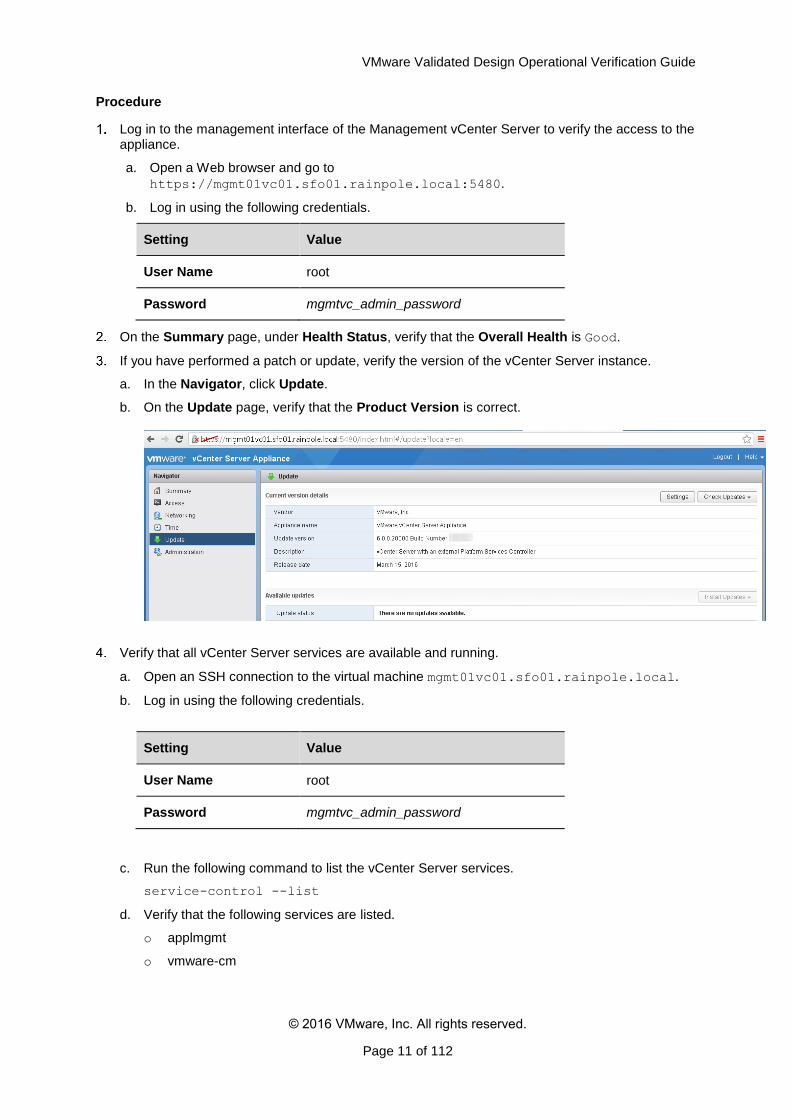
If you have performed a patch or update, verify the version of the vCenter Server instance.
a. In the Navigator, click Update.
b. On the Update page, verify that the Product Version is correct.
Verify that all vCenter Server services are available and running.
a. Open an SSH connection to the virtual machine mgmt01vc01.sfo01.rainpole.local.
b. Log in using the following credentials.
Setting Value
User Name root
Password mgmtvc_admin_password
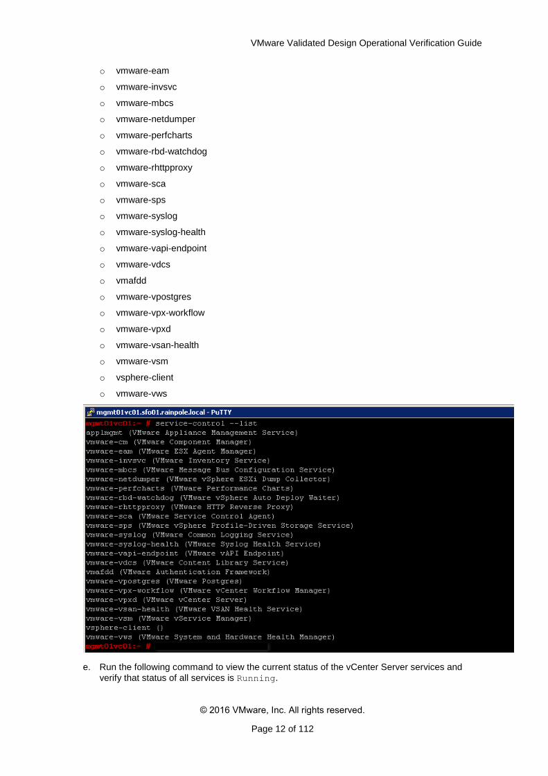
c. Run the following command to list the vCenter Server services.
service-control --list
d. Verify that the following services are listed.
o applmgmt
o vmware-cm
VMware Validated Design Operational Verification Guide
© 2016 VMware, Inc. All rights reserved.
Page 12 of 112
o vmware-eam
o vmware-invsvc
o vmware-mbcs
o vmware-netdumper
o vmware-perfcharts
o vmware-rbd-watchdog
o vmware-rhttpproxy
o vmware-sca
o vmware-sps
o vmware-syslog
o vmware-syslog-health
o vmware-vapi-endpoint
o vmware-vdcs
o vmafdd
o vmware-vpostgres
o vmware-vpx-workflow
o vmware-vpxd
o vmware-vsan-health
o vmware-vsm
o vsphere-client
o vmware-vws
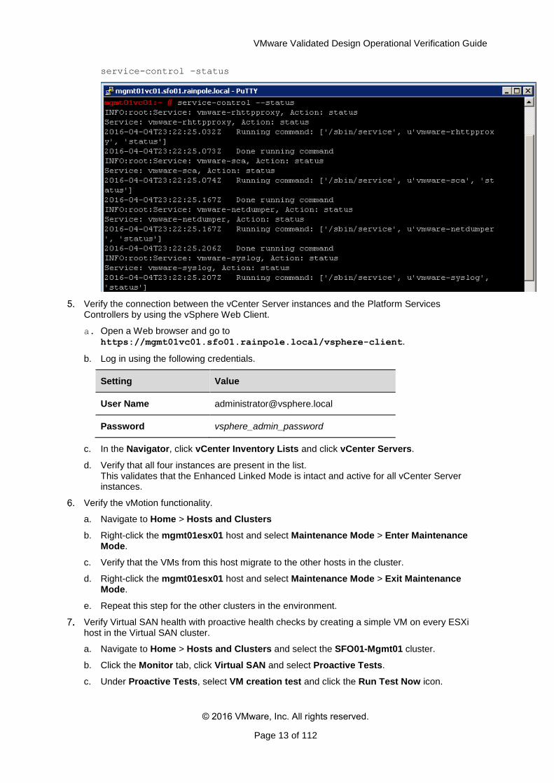
e. Run the following command to view the current status of the vCenter Server services and
verify that status of all services is Running.
VMware Validated Design Operational Verification Guide
© 2016 VMware, Inc. All rights reserved.
Page 13 of 112
service-control –status
Verify the connection between the vCenter Server instances and the Platform Services Controllers by using the vSphere Web Client.
a. Open a Web browser and go to https://mgmt01vc01.sfo01.rainpole.local/vsphere-client.
b. Log in using the following credentials.
Setting Value
User Name [email protected]
Password vsphere_admin_password
c. In the Navigator, click vCenter Inventory Lists and click vCenter Servers.
d. Verify that all four instances are present in the list. This validates that the Enhanced Linked Mode is intact and active for all vCenter Server instances.
Verify the vMotion functionality.
a. Navigate to Home > Hosts and Clusters
b. Right-click the mgmt01esx01 host and select Maintenance Mode > Enter Maintenance Mode.
c. Verify that the VMs from this host migrate to the other hosts in the cluster.
d. Right-click the mgmt01esx01 host and select Maintenance Mode > Exit Maintenance Mode.
e. Repeat this step for the other clusters in the environment.
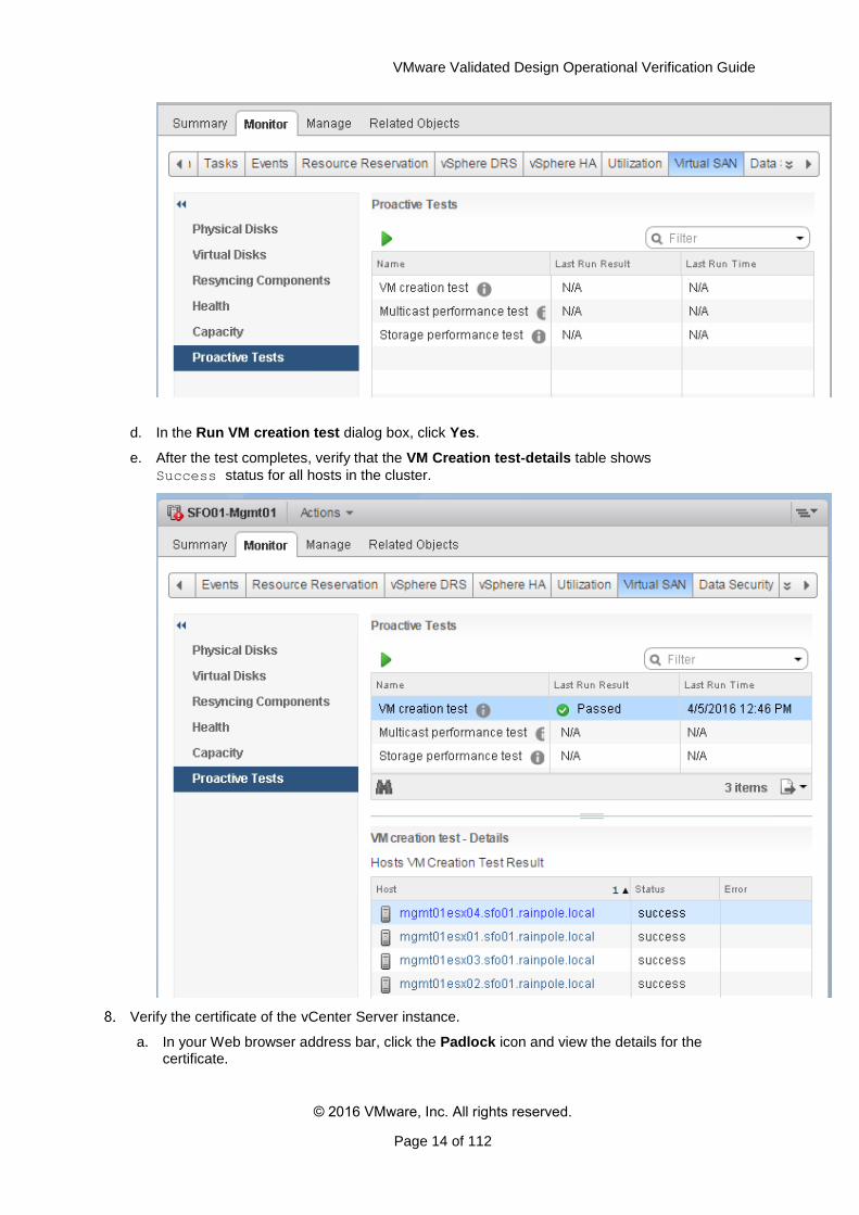
Verify Virtual SAN health with proactive health checks by creating a simple VM on every ESXi host in the Virtual SAN cluster.
a. Navigate to Home > Hosts and Clusters and select the SFO01-Mgmt01 cluster.
b. Click the Monitor tab, click Virtual SAN and select Proactive Tests.
c. Under Proactive Tests, select VM creation test and click the Run Test Now icon.
VMware Validated Design Operational Verification Guide
© 2016 VMware, Inc. All rights reserved.
Page 14 of 112
d. In the Run VM creation test dialog box, click Yes.
e. After the test completes, verify that the VM Creation test-details table shows
Success status for all hosts in the cluster.
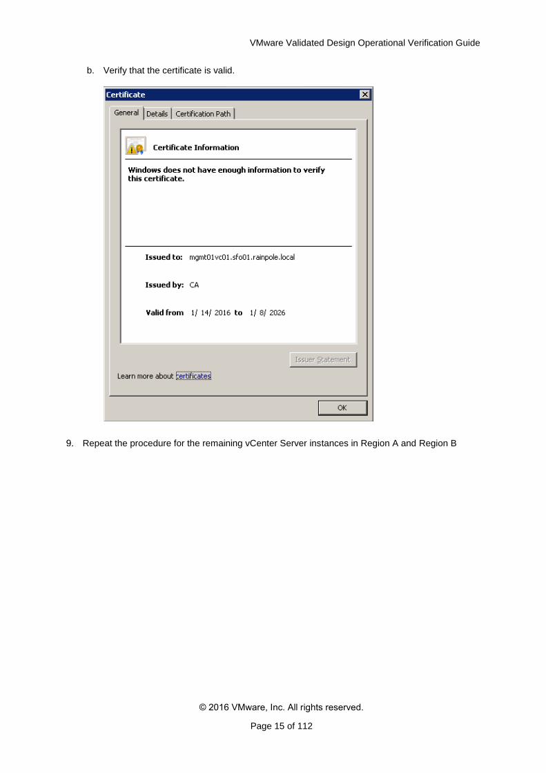
Verify the certificate of the vCenter Server instance.
a. In your Web browser address bar, click the Padlock icon and view the details for the certificate.
VMware Validated Design Operational Verification Guide
© 2016 VMware, Inc. All rights reserved.
Page 15 of 112
b. Verify that the certificate is valid.
Repeat the procedure for the remaining vCenter Server instances in Region A and Region B
VMware Validated Design Operational Verification Guide
© 2016 VMware, Inc. All rights reserved.
Page 16 of 112
3. Validate the Cloud Management Platform
After a maintenance like patch, update, restore, failover, or failback, validate the Cloud Management
Platform (vRealize Automation, vRealize Orchestrator and vRealize Business components) and make
sure they work as expected.
Verify the Power Status and Address of All vRealize Automation, vRealize Orchestrator and vRealize Business VMs
Verify the Version, Service Status and Configuration of vRealize Automation Appliances
Verify the Status of IaaS Web Server and Manager Service Nodes of vRealize Automation
Verify the Version and Service Status of vRealize Automation Windows Nodes
Verify the Version, Status and Configuration of vRealize Orchestrator VMs
Verify the Status of the Distributed Execution Managers and vSphere Proxy Agents in vRealize Automation
Verify the Status of vRealize Automation Integration with Active Directory
Verify the Version, Service Status and Configuration of the vRealize Business VMs
Request a Single-Machine Blueprint from the Service Catalog of vRealize Automation
Verify the Cloud Management Platform Load Balancing
3.1 Verify the Power Status and Address of All vRealize Automation, vRealize Orchestrator and vRealize Business VMs
All virtual machines of vRealize Automation, vRealize Orchestrator and vRealize Business must be running for a fully-functional cloud platform.
Prerequisites
Verify that all virtual machines of vRealize Automation, vRealize Orchestrator and vRealize Business are started in the order defined in the SDDC Startup and Shutdown section.
Procedure
Log in to vCenter Server by using the vSphere Web Client.
a. Open a Web browser and go to the following URL.
Region Value
Region A
https://mgmt01vc01.sfo01.rainpole.local/vsphere-
client
Region B
https://mgmt01vc01.sfo01.rainpole.local/vsphere-
client
b. Log in using the following credentials.
Setting Value
User Name [email protected]
VMware Validated Design Operational Verification Guide
© 2016 VMware, Inc. All rights reserved.
Page 17 of 112
Password vsphere_admin_password
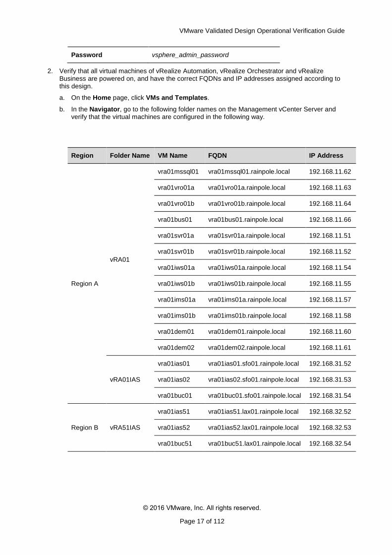
2. Verify that all virtual machines of vRealize Automation, vRealize Orchestrator and vRealize Business are powered on, and have the correct FQDNs and IP addresses assigned according to this design.
a. On the Home page, click VMs and Templates.
b. In the Navigator, go to the following folder names on the Management vCenter Server and verify that the virtual machines are configured in the following way.
Region Folder Name VM Name FQDN IP Address
Region A
vRA01
vra01mssql01 vra01mssql01.rainpole.local 192.168.11.62
vra01vro01a vra01vro01a.rainpole.local 192.168.11.63
vra01vro01b vra01vro01b.rainpole.local 192.168.11.64
vra01bus01 vra01bus01.rainpole.local 192.168.11.66
vra01svr01a vra01svr01a.rainpole.local 192.168.11.51
vra01svr01b vra01svr01b.rainpole.local 192.168.11.52
vra01iws01a vra01iws01a.rainpole.local 192.168.11.54
vra01iws01b vra01iws01b.rainpole.local 192.168.11.55
vra01ims01a vra01ims01a.rainpole.local 192.168.11.57
vra01ims01b vra01ims01b.rainpole.local 192.168.11.58
vra01dem01 vra01dem01.rainpole.local 192.168.11.60
vra01dem02 vra01dem02.rainpole.local 192.168.11.61
vRA01IAS
vra01ias01 vra01ias01.sfo01.rainpole.local 192.168.31.52
vra01ias02 vra01ias02.sfo01.rainpole.local 192.168.31.53
vra01buc01 vra01buc01.sfo01.rainpole.local 192.168.31.54
Region B vRA51IAS
vra01ias51 vra01ias51.lax01.rainpole.local 192.168.32.52
vra01ias52 vra01ias52.lax01.rainpole.local 192.168.32.53
vra01buc51 vra01buc51.lax01.rainpole.local 192.168.32.54
VMware Validated Design Operational Verification Guide
© 2016 VMware, Inc. All rights reserved.
Page 18 of 112
3.2 Verify the Version, Service Status and Configuration of vRealize Automation Appliances
After you perform software maintenance in the Software-Defined Data Center (SDDC), verify that the version and the configuration of the two vRealize Automation server appliances are intact.
After you patch, update, restore, failover, or failback the vRealize Automation appliances
vra01svr01a.rainpole.local and vra01svr01b.rainpole.local, verify the version, the
service status and the configuration of each of them. The two appliances share the same configuration except for static IP address and host name.
.
Table 3. Network Parameters for the vRealize Automation Appliances
vRealize Appliance
Appliance Management Console URL IP Address FQDN
vRealize Appliance A
https://vra01svr01a.rainpole.local:5480 192.168.11.51 vra01svr01a.rainpole.local
vRealize Appliance B
https://vra01svr01b.rainpole.local:5480 192.168.11.52 vra01svr01b.rainpole.local
Procedure
Verify the authentication of vRealize Automation appliance to the appliance management console.
a. Open a Web browser and go to https://vra01svr01a.rainpole.local:5480.
b. Log in using the following credentials.
Setting Value
User Name root
Password vra_appliance_root_password
c. Verify that the login authentication is successful.
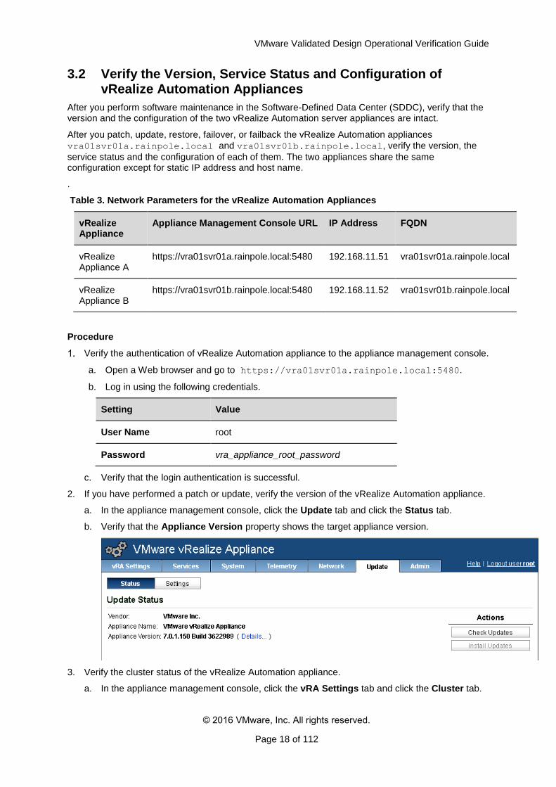
2. If you have performed a patch or update, verify the version of the vRealize Automation appliance.
a. In the appliance management console, click the Update tab and click the Status tab.
b. Verify that the Appliance Version property shows the target appliance version.
3. Verify the cluster status of the vRealize Automation appliance.
a. In the appliance management console, click the vRA Settings tab and click the Cluster tab.
VMware Validated Design Operational Verification Guide
© 2016 VMware, Inc. All rights reserved.
Page 19 of 112
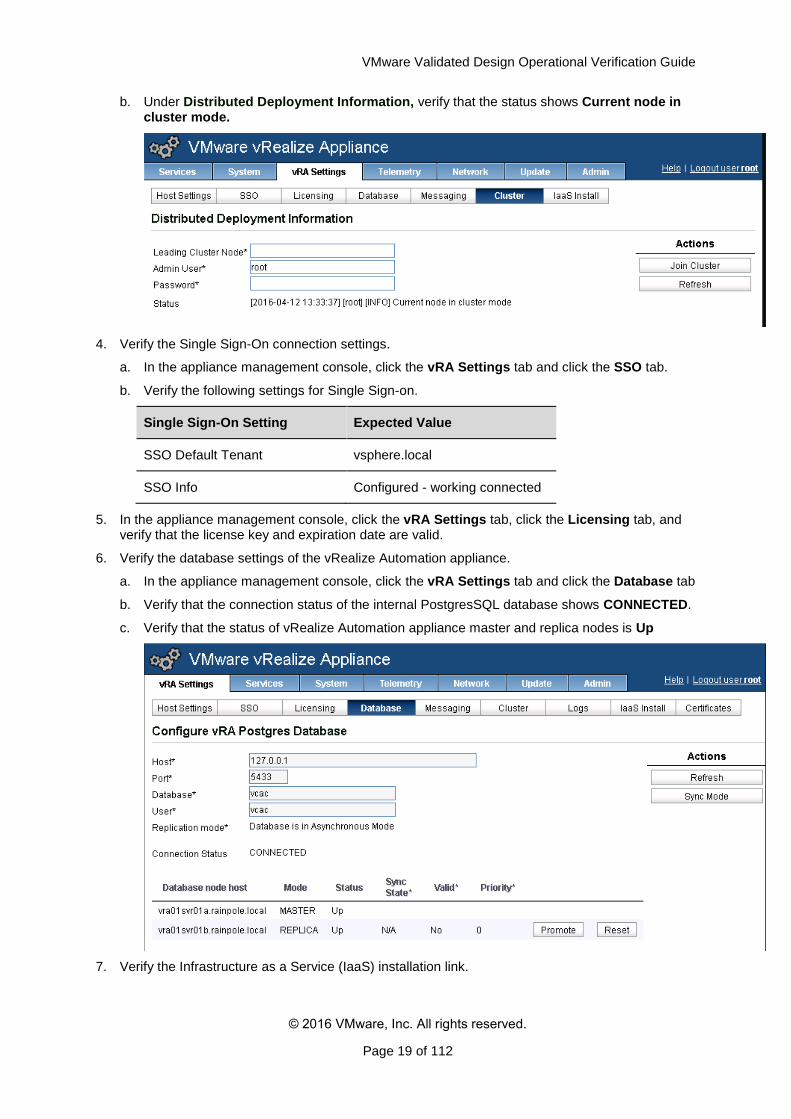
b. Under Distributed Deployment Information, verify that the status shows Current node in cluster mode.
4. Verify the Single Sign-On connection settings.
a. In the appliance management console, click the vRA Settings tab and click the SSO tab.
b. Verify the following settings for Single Sign-on.
Single Sign-On Setting Expected Value
SSO Default Tenant vsphere.local
SSO Info Configured - working connected
5. In the appliance management console, click the vRA Settings tab, click the Licensing tab, and verify that the license key and expiration date are valid.
6. Verify the database settings of the vRealize Automation appliance.
a. In the appliance management console, click the vRA Settings tab and click the Database tab
b. Verify that the connection status of the internal PostgresSQL database shows CONNECTED.
c. Verify that the status of vRealize Automation appliance master and replica nodes is Up
7. Verify the Infrastructure as a Service (IaaS) installation link.
VMware Validated Design Operational Verification Guide
© 2016 VMware, Inc. All rights reserved.
Page 20 of 112
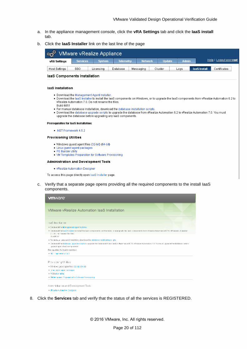
a. In the appliance management console, click the vRA Settings tab and click the IaaS install tab.
b. Click the IaaS Installer link on the last line of the page
c. Verify that a separate page opens providing all the required components to the install IaaS components.
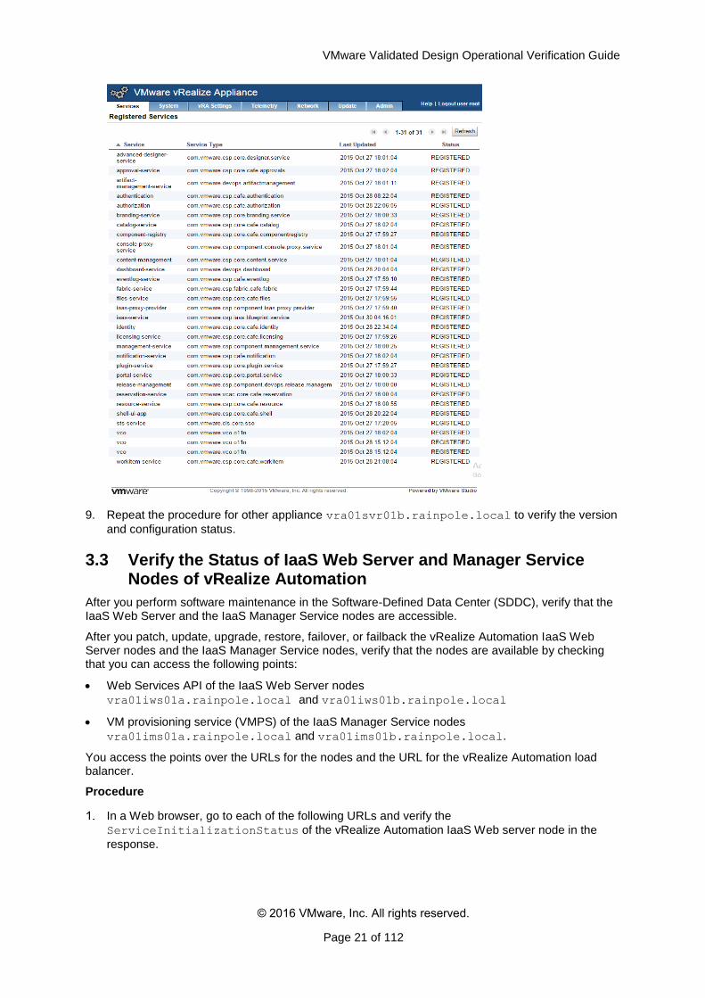
8. Click the Services tab and verify that the status of all the services is REGISTERED.
VMware Validated Design Operational Verification Guide
© 2016 VMware, Inc. All rights reserved.
Page 21 of 112
9. Repeat the procedure for other appliance vra01svr01b.rainpole.local to verify the version
and configuration status.
3.3 Verify the Status of IaaS Web Server and Manager Service Nodes of vRealize Automation
After you perform software maintenance in the Software-Defined Data Center (SDDC), verify that the IaaS Web Server and the IaaS Manager Service nodes are accessible.
After you patch, update, upgrade, restore, failover, or failback the vRealize Automation IaaS Web Server nodes and the IaaS Manager Service nodes, verify that the nodes are available by checking that you can access the following points:
Web Services API of the IaaS Web Server nodes
vra01iws01a.rainpole.local and vra01iws01b.rainpole.local
VM provisioning service (VMPS) of the IaaS Manager Service nodes
vra01ims01a.rainpole.local and vra01ims01b.rainpole.local.
You access the points over the URLs for the nodes and the URL for the vRealize Automation load balancer.
Procedure
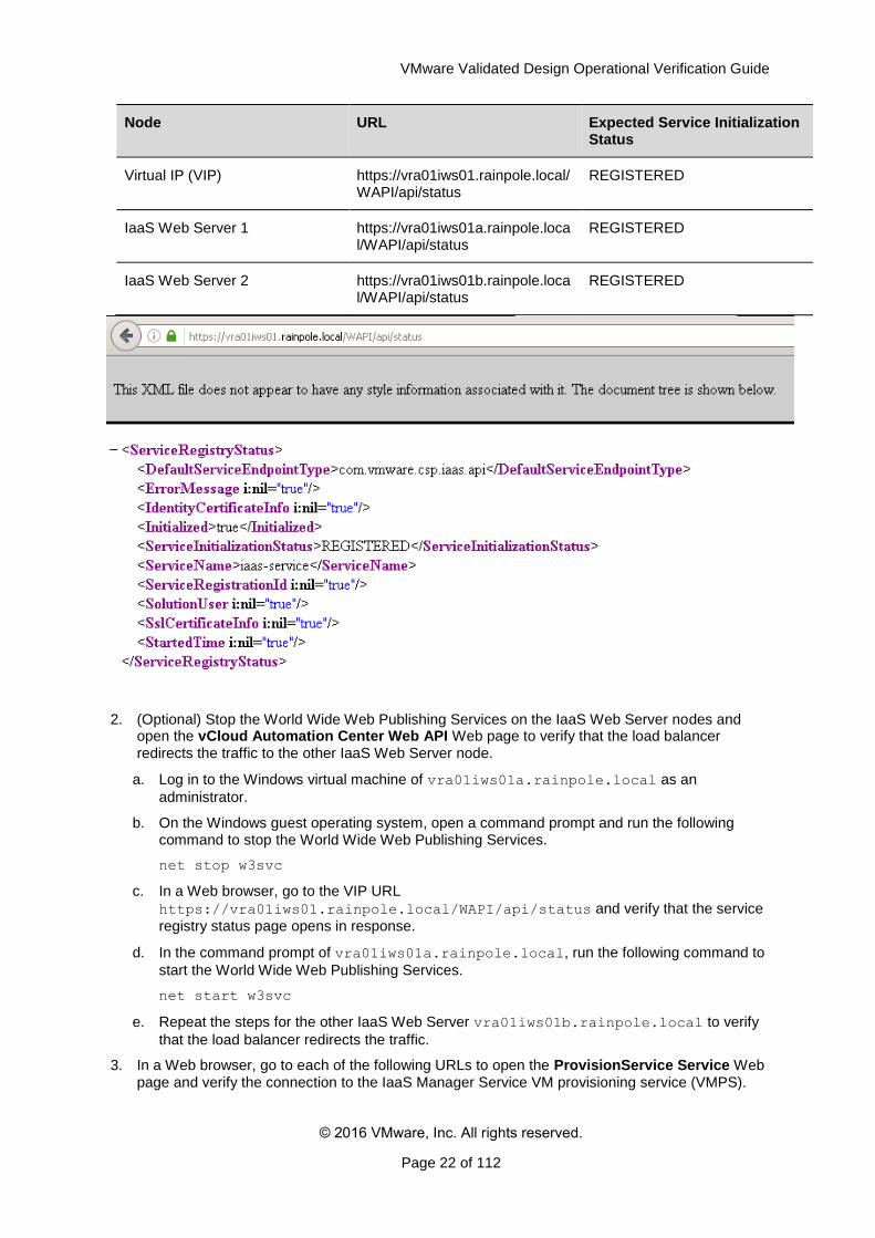
In a Web browser, go to each of the following URLs and verify the
ServiceInitializationStatus of the vRealize Automation IaaS Web server node in the
response.
VMware Validated Design Operational Verification Guide
© 2016 VMware, Inc. All rights reserved.
Page 22 of 112
Node URL Expected Service Initialization Status
Virtual IP (VIP) https://vra01iws01.rainpole.local/WAPI/api/status
REGISTERED
IaaS Web Server 1 https://vra01iws01a.rainpole.local/WAPI/api/status
REGISTERED
IaaS Web Server 2 https://vra01iws01b.rainpole.local/WAPI/api/status
REGISTERED
2. (Optional) Stop the World Wide Web Publishing Services on the IaaS Web Server nodes and open the vCloud Automation Center Web API Web page to verify that the load balancer redirects the traffic to the other IaaS Web Server node.
a. Log in to the Windows virtual machine of vra01iws01a.rainpole.local as an
administrator.
b. On the Windows guest operating system, open a command prompt and run the following command to stop the World Wide Web Publishing Services.
net stop w3svc
c. In a Web browser, go to the VIP URL
https://vra01iws01.rainpole.local/WAPI/api/status and verify that the service
registry status page opens in response.
d. In the command prompt of vra01iws01a.rainpole.local, run the following command to
start the World Wide Web Publishing Services.
net start w3svc
e. Repeat the steps for the other IaaS Web Server vra01iws01b.rainpole.local to verify
that the load balancer redirects the traffic.
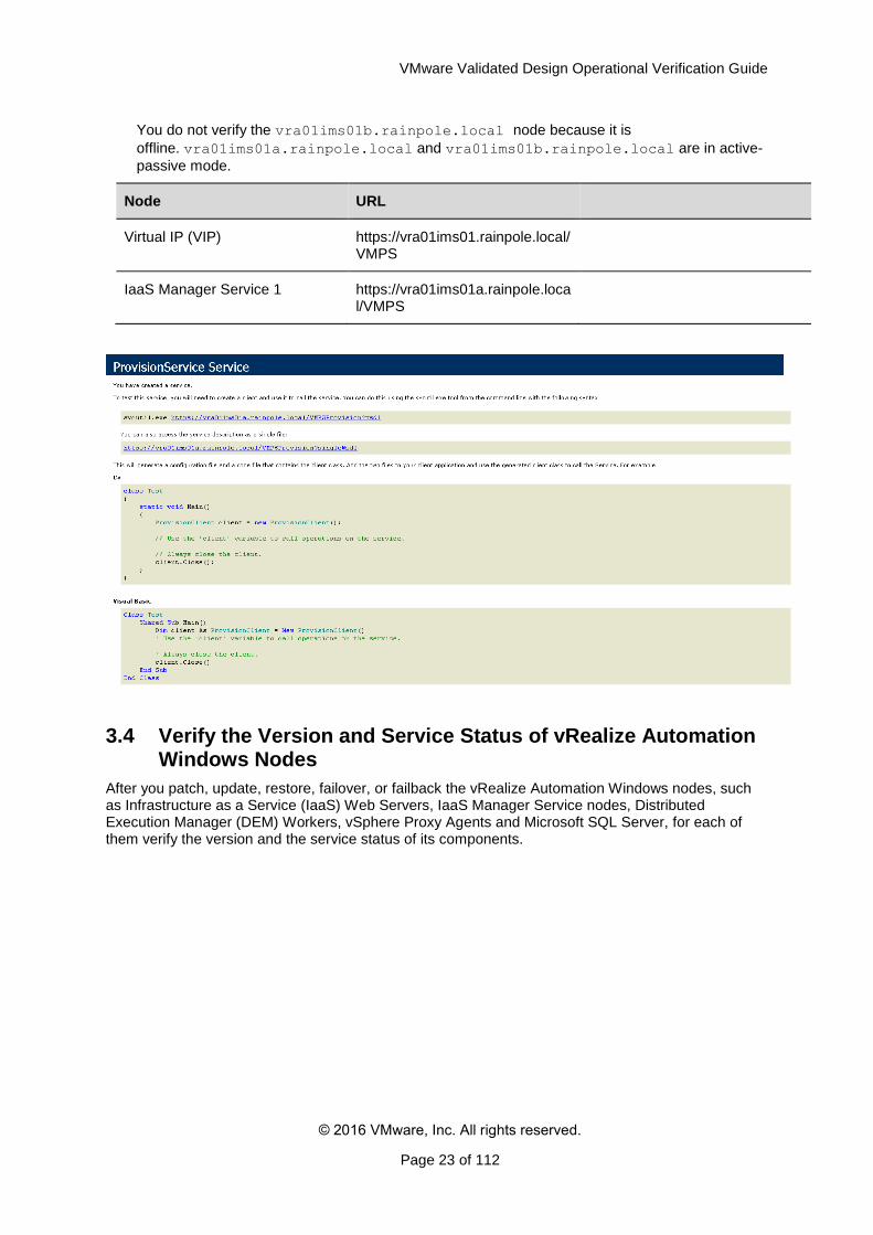
3. In a Web browser, go to each of the following URLs to open the ProvisionService Service Web page and verify the connection to the IaaS Manager Service VM provisioning service (VMPS).
VMware Validated Design Operational Verification Guide
© 2016 VMware, Inc. All rights reserved.
Page 23 of 112
You do not verify the vra01ims01b.rainpole.local node because it is
offline. vra01ims01a.rainpole.local and vra01ims01b.rainpole.local are in active-
passive mode.
Node URL
Virtual IP (VIP) https://vra01ims01.rainpole.local/VMPS
IaaS Manager Service 1 https://vra01ims01a.rainpole.local/VMPS
3.4 Verify the Version and Service Status of vRealize Automation Windows Nodes
After you patch, update, restore, failover, or failback the vRealize Automation Windows nodes, such as Infrastructure as a Service (IaaS) Web Servers, IaaS Manager Service nodes, Distributed Execution Manager (DEM) Workers, vSphere Proxy Agents and Microsoft SQL Server, for each of them verify the version and the service status of its components.
VMware Validated Design Operational Verification Guide
© 2016 VMware, Inc. All rights reserved.
Page 24 of 112
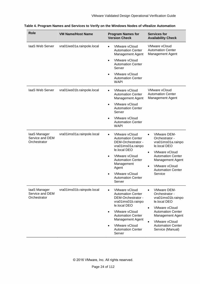
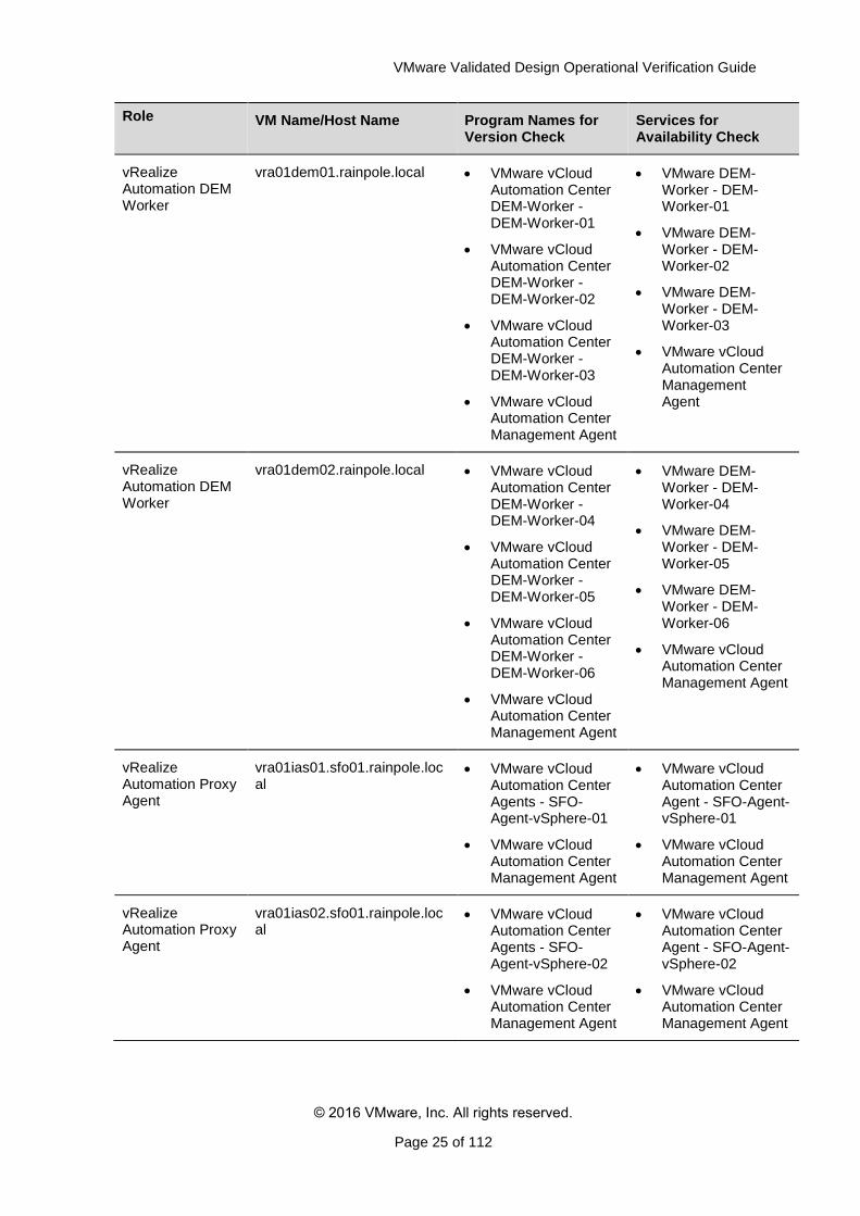
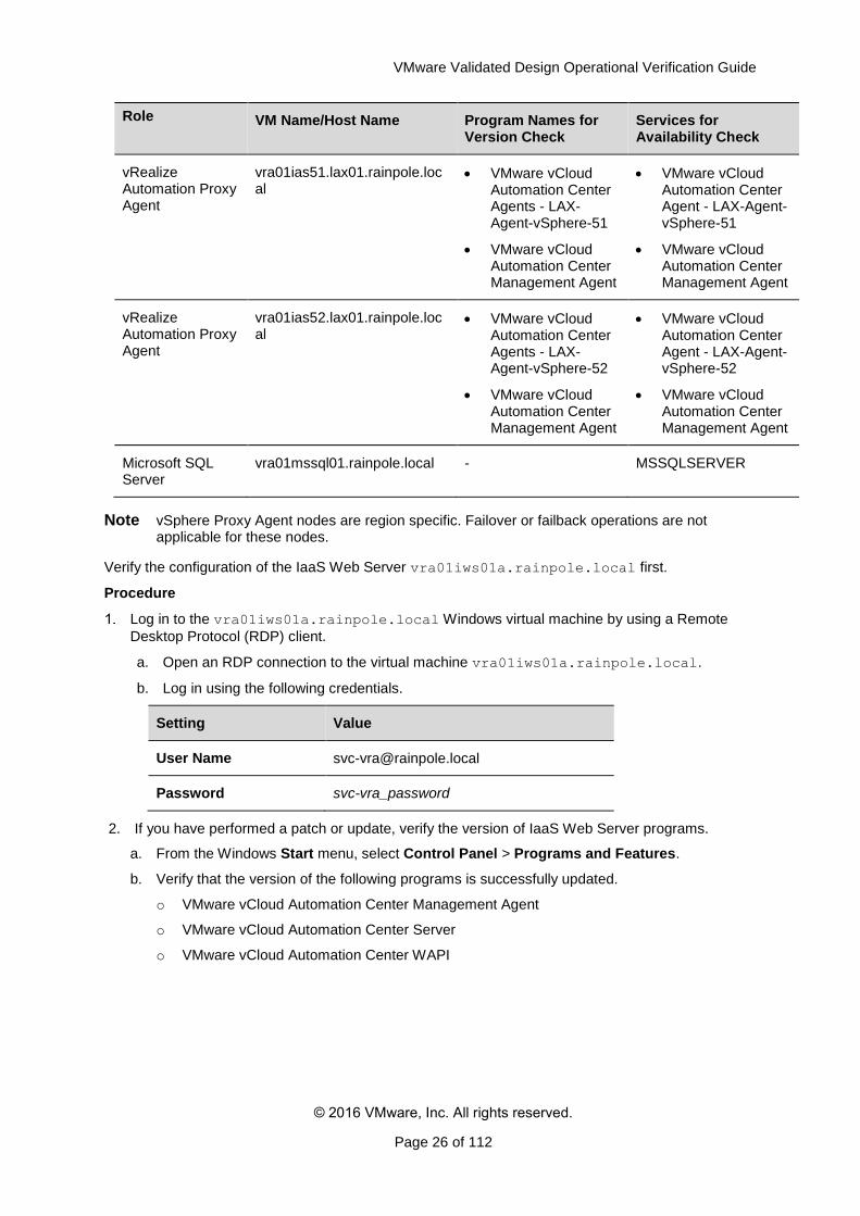
Table 4. Program Names and Services to Verify on the Windows Nodes of vRealize Automation
Role VM Name/Host Name Program Names for Version Check
Services for Availability Check
IaaS Web Server vra01iws01a.rainpole.local VMware vCloud Automation Center Management Agent
VMware vCloud Automation Center Server
VMware vCloud Automation Center WAPI
VMware vCloud Automation Center Management Agent
IaaS Web Server vra01iws01b.rainpole.local VMware vCloud Automation Center Management Agent
VMware vCloud Automation Center Server
VMware vCloud Automation Center WAPI
VMware vCloud Automation Center Management Agent
IaaS Manager Service and DEM Orchestrator
vra01ims01a.rainpole.local VMware vCloud Automation Center DEM-Orchestrator - vra01ims01a.rainpole.local DEO
VMware vCloud Automation Center Management Agent
VMware vCloud Automation Center Server
VMware DEM-Orchestrator - vra01ims01a.rainpole.local DEO
VMware vCloud Automation Center Management Agent
VMware vCloud Automation Center Service
IaaS Manager Service and DEM Orchestrator
vra01ims01b.rainpole.local VMware vCloud Automation Center DEM-Orchestrator - vra01ims01b.rainpole.local DEO
VMware vCloud Automation Center Management Agent
VMware vCloud Automation Center Server
VMware DEM-Orchestrator - vra01ims01b.rainpole.local DEO
VMware vCloud Automation Center Management Agent
VMware vCloud Automation Center Service (Manual)
VMware Validated Design Operational Verification Guide
© 2016 VMware, Inc. All rights reserved.
Page 25 of 112
Role VM Name/Host Name Program Names for Version Check
Services for Availability Check
vRealize Automation DEM Worker
vra01dem01.rainpole.local VMware vCloud Automation Center DEM-Worker - DEM-Worker-01
VMware vCloud Automation Center DEM-Worker - DEM-Worker-02
VMware vCloud Automation Center DEM-Worker - DEM-Worker-03
VMware vCloud Automation Center Management Agent
VMware DEM-Worker - DEM-Worker-01
VMware DEM-Worker - DEM-Worker-02
VMware DEM-Worker - DEM-Worker-03
VMware vCloud Automation Center Management Agent
vRealize Automation DEM Worker
vra01dem02.rainpole.local VMware vCloud Automation Center DEM-Worker - DEM-Worker-04
VMware vCloud Automation Center DEM-Worker - DEM-Worker-05
VMware vCloud Automation Center DEM-Worker - DEM-Worker-06
VMware vCloud Automation Center Management Agent
VMware DEM-Worker - DEM-Worker-04
VMware DEM-Worker - DEM-Worker-05
VMware DEM-Worker - DEM-Worker-06
VMware vCloud Automation Center Management Agent
vRealize Automation Proxy Agent
vra01ias01.sfo01.rainpole.local
VMware vCloud Automation Center Agents - SFO-Agent-vSphere-01
VMware vCloud Automation Center Management Agent
VMware vCloud Automation Center Agent - SFO-Agent-vSphere-01
VMware vCloud Automation Center Management Agent
vRealize Automation Proxy Agent
vra01ias02.sfo01.rainpole.local
VMware vCloud Automation Center Agents - SFO-Agent-vSphere-02
VMware vCloud Automation Center Management Agent
VMware vCloud Automation Center Agent - SFO-Agent-vSphere-02
VMware vCloud Automation Center Management Agent
VMware Validated Design Operational Verification Guide
© 2016 VMware, Inc. All rights reserved.
Page 26 of 112
Role VM Name/Host Name Program Names for Version Check
Services for Availability Check
vRealize Automation Proxy Agent
vra01ias51.lax01.rainpole.local
VMware vCloud Automation Center Agents - LAX-Agent-vSphere-51
VMware vCloud Automation Center Management Agent
VMware vCloud Automation Center Agent - LAX-Agent-vSphere-51
VMware vCloud Automation Center Management Agent
vRealize Automation Proxy Agent
vra01ias52.lax01.rainpole.local
VMware vCloud Automation Center Agents - LAX-Agent-vSphere-52
VMware vCloud Automation Center Management Agent
VMware vCloud Automation Center Agent - LAX-Agent-vSphere-52
VMware vCloud Automation Center Management Agent
Microsoft SQL Server
vra01mssql01.rainpole.local - MSSQLSERVER
Note vSphere Proxy Agent nodes are region specific. Failover or failback operations are not applicable for these nodes.
Verify the configuration of the IaaS Web Server vra01iws01a.rainpole.local first.
Procedure
Log in to the vra01iws01a.rainpole.local Windows virtual machine by using a Remote
Desktop Protocol (RDP) client.
a. Open an RDP connection to the virtual machine vra01iws01a.rainpole.local.
b. Log in using the following credentials.
Setting Value
User Name [email protected]
Password svc-vra_password
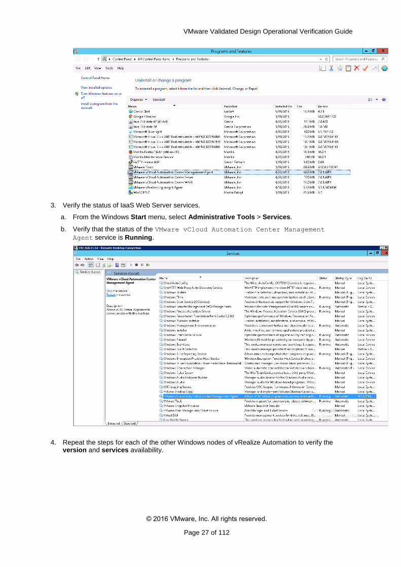
2. If you have performed a patch or update, verify the version of IaaS Web Server programs.
a. From the Windows Start menu, select Control Panel > Programs and Features.
b. Verify that the version of the following programs is successfully updated.
o VMware vCloud Automation Center Management Agent
o VMware vCloud Automation Center Server
o VMware vCloud Automation Center WAPI
VMware Validated Design Operational Verification Guide
© 2016 VMware, Inc. All rights reserved.
Page 27 of 112
3. Verify the status of IaaS Web Server services.
a. From the Windows Start menu, select Administrative Tools > Services.
b. Verify that the status of the VMware vCloud Automation Center Management
Agent service is Running.
4. Repeat the steps for each of the other Windows nodes of vRealize Automation to verify the version and services availability.
VMware Validated Design Operational Verification Guide
© 2016 VMware, Inc. All rights reserved.
Page 28 of 112
3.5 Verify the Version, Status and Configuration of the vRealize Orchestrator VMs
Make sure that the two servers in the vRealize Orchestrator cluster are operational after a patch,
update, restore, failover, or failback operation.
Procedure
Verify that the vRealize Orchestrator appliance management interface is operational.
a. Open a Web browser and go to https://vra01vro01a.rainpole.local:5480.
b. Log in using the following credentials.
Setting Value
User Name root
Password vro_appliance_A_root_pwd
c. (Optional) Log in to the second node of vRealize Orchestrator Appliance
https://vra01vro01b.rainpole.local:5480 and verify the authentication.
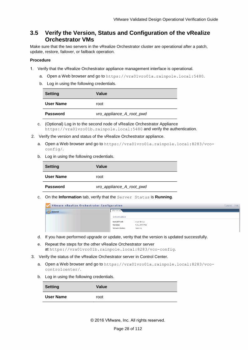
2. Verify the version and status of the vRealize Orchestrator appliance.
a. Open a Web browser and go to https://vra01vro01a.rainpole.local:8283/vco-
config/.
b. Log in using the following credentials.
Setting Value
User Name root
Password vro_appliance_A_root_pwd
c. On the Information tab, verify that the Server Status is Running.
d. If you have performed upgrade or update, verity that the version is updated successfully.
e. Repeat the steps for the other vRealize Orchestrator server
at https://vra01vro01b.rainpole.local:8283/vco-config.
3. Verify the status of the vRealize Orchestrator server in Control Center.
a. Open a Web browser and go to https://vra01vro01a.rainpole.local:8283/vco-
controlcenter/.
b. Log in using the following credentials.
Setting Value
User Name root
VMware Validated Design Operational Verification Guide
© 2016 VMware, Inc. All rights reserved.
Page 29 of 112
Password vro_appliance_A_root_pwd
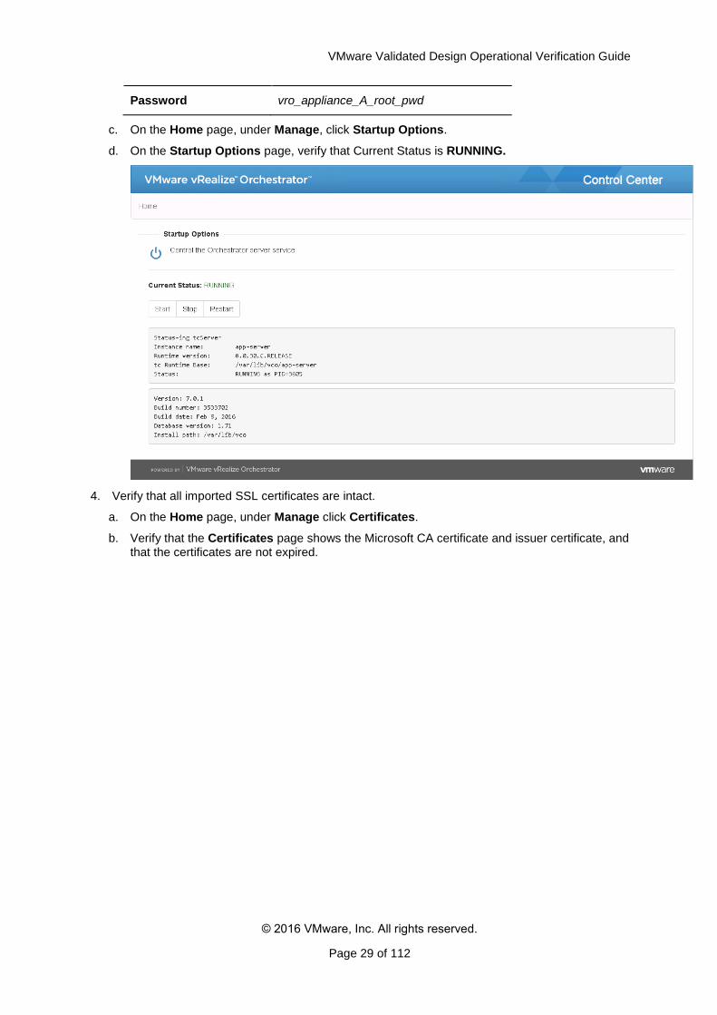
c. On the Home page, under Manage, click Startup Options.
d. On the Startup Options page, verify that Current Status is RUNNING.
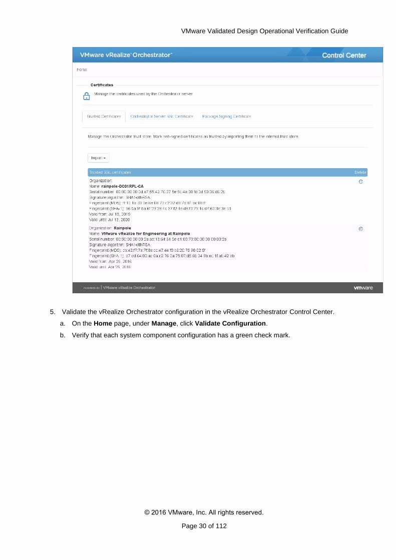
4. Verify that all imported SSL certificates are intact.
a. On the Home page, under Manage click Certificates.
b. Verify that the Certificates page shows the Microsoft CA certificate and issuer certificate, and that the certificates are not expired.
VMware Validated Design Operational Verification Guide
© 2016 VMware, Inc. All rights reserved.
Page 30 of 112
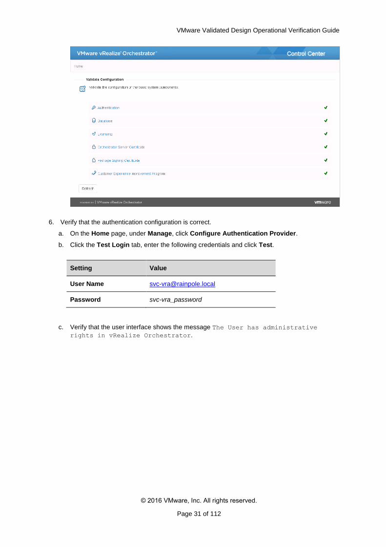
5. Validate the vRealize Orchestrator configuration in the vRealize Orchestrator Control Center.
a. On the Home page, under Manage, click Validate Configuration.
b. Verify that each system component configuration has a green check mark.
VMware Validated Design Operational Verification Guide
© 2016 VMware, Inc. All rights reserved.
Page 31 of 112
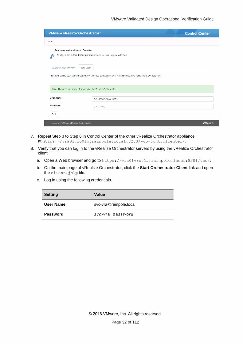
6. Verify that the authentication configuration is correct.
a. On the Home page, under Manage, click Configure Authentication Provider.
b. Click the Test Login tab, enter the following credentials and click Test.
Setting Value
User Name [email protected]
Password svc-vra_password
c. Verify that the user interface shows the message The User has administrative
rights in vRealize Orchestrator.
VMware Validated Design Operational Verification Guide
© 2016 VMware, Inc. All rights reserved.
Page 32 of 112
7. Repeat Step 3 to Step 6 in Control Center of the other vRealize Orchestrator appliance
at https://vra01vro01b.rainpole.local:8283/vco-controlcenter/.
8. Verify that you can log in to the vRealize Orchestrator servers by using the vRealize Orchestrator client.
a. Open a Web browser and go to https://vra01vro01a.rainpole.local:8281/vco/.
b. On the main page of vRealize Orchestrator, click the Start Orchestrator Client link and open
the client.jnlp file.
c. Log in using the following credentials.
Setting Value
User Name [email protected]
Password svc-vra_password

VMware Validated Design Operational Verification Guide
© 2016 VMware, Inc. All rights reserved.
Page 33 of 112
d. If a certificate warning appears, ignore it.
e. Verify that the login is successful.
f. Repeat the step for the other vRealize Orchestrator appliance at
https://vra01vro01b.rainpole.local:8281/vco/ to verify that the login is
successful.
9. Verify vRealize Orchestrator endpoint data collection in the vRealize Automation Rainpole portal.
a. Open a Web browser and go
to https://vra01svr01.rainpole.local/vcac/org/rainpole.
b. Log in using the following credentials.
Setting Value
VMware Validated Design Operational Verification Guide
© 2016 VMware, Inc. All rights reserved.
Page 34 of 112
User Name ITAC-TenantAdmin
Password ra inpole_tenant_admin_password
Domain ra inpole. local
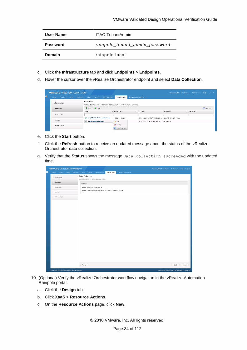
c. Click the Infrastructure tab and click Endpoints > Endpoints.
d. Hover the cursor over the vRealize Orchestrator endpoint and select Data Collection.
e. Click the Start button.
f. Click the Refresh button to receive an updated message about the status of the vRealize Orchestrator data collection.
g. Verify that the Status shows the message Data collection succeeded with the updated
time.
10. (Optional) Verify the vRealize Orchestrator workflow navigation in the vRealize Automation Rainpole portal.
a. Click the Design tab.
b. Click XaaS > Resource Actions.
c. On the Resource Actions page, click New.
VMware Validated Design Operational Verification Guide
© 2016 VMware, Inc. All rights reserved.
Page 35 of 112
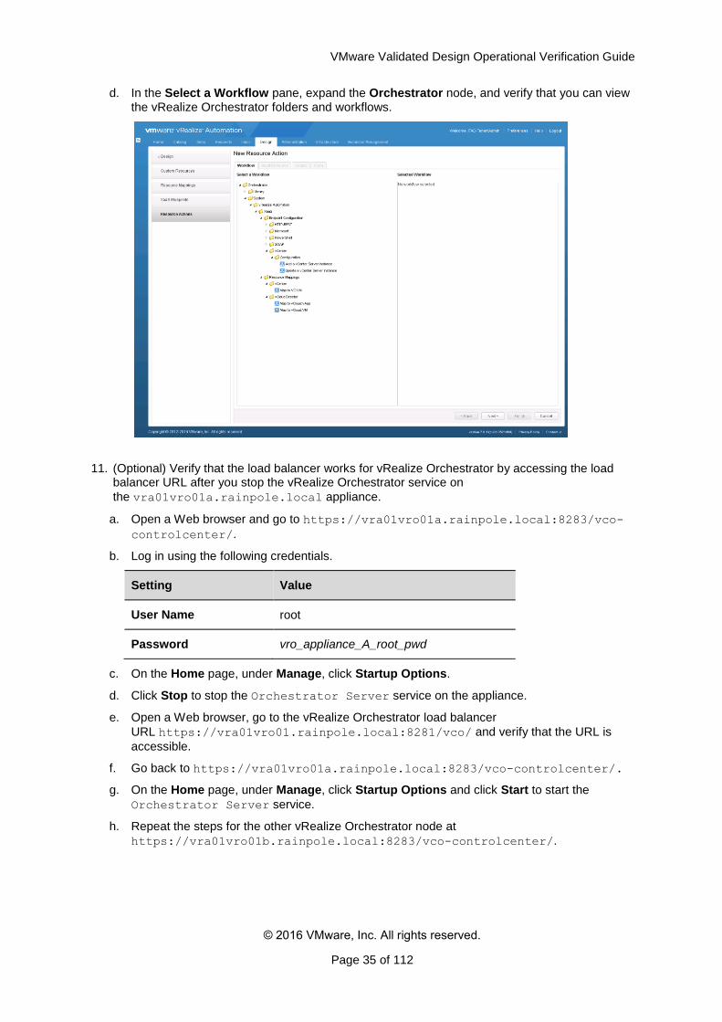
d. In the Select a Workflow pane, expand the Orchestrator node, and verify that you can view the vRealize Orchestrator folders and workflows.
11. (Optional) Verify that the load balancer works for vRealize Orchestrator by accessing the load balancer URL after you stop the vRealize Orchestrator service on
the vra01vro01a.rainpole.local appliance.
a. Open a Web browser and go to https://vra01vro01a.rainpole.local:8283/vco-
controlcenter/.
b. Log in using the following credentials.
Setting Value
User Name root
Password vro_appliance_A_root_pwd
c. On the Home page, under Manage, click Startup Options.
d. Click Stop to stop the Orchestrator Server service on the appliance.
e. Open a Web browser, go to the vRealize Orchestrator load balancer
URL https://vra01vro01.rainpole.local:8281/vco/ and verify that the URL is
accessible.
f. Go back to https://vra01vro01a.rainpole.local:8283/vco-controlcenter/.
g. On the Home page, under Manage, click Startup Options and click Start to start the
Orchestrator Server service.
h. Repeat the steps for the other vRealize Orchestrator node at
https://vra01vro01b.rainpole.local:8283/vco-controlcenter/.
VMware Validated Design Operational Verification Guide
© 2016 VMware, Inc. All rights reserved.
Page 36 of 112
3.6 Verify the Status of the Distributed Execution Managers and vSphere Proxy Agents in vRealize Automation
After you perform software maintenance, verify that status the Distributed Execution Manager (DEM) and IaaS vSphere Proxy Agents components
After you patch, update, restore, failover, or failback vRealize Automation, verify that the Distributed Execution Manager (DEM) Orchestrators and Workers are online, and that the IaaS vSphere Proxy Agents that connect vRealize Automation to the compute pods are online.
Procedure
Log in to the vRealize Automation Rainpole portal.
a. Open a Web browser and go
to https://vra01svr01.rainpole.local/vcac/org/rainpole.
b. Log in using the following credentials.
Setting Value
User Name ITAC-TenantAdmin
Password ra inpole_tenant_admin_password
Domain ra inpole. local
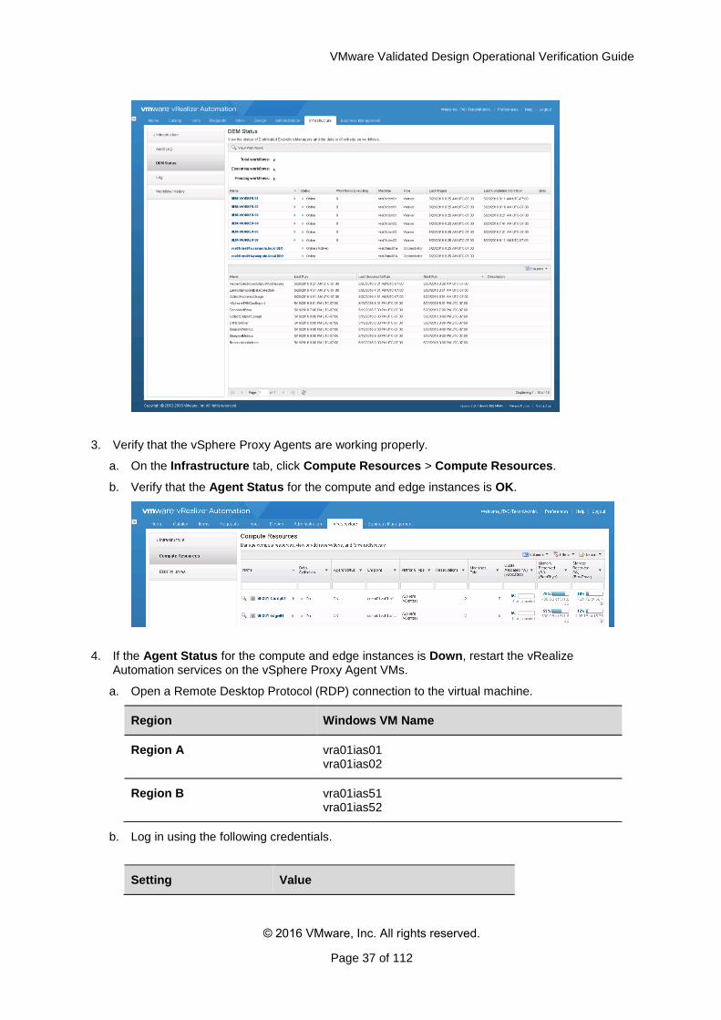
2. Verify the status of the DEM nodes.
a. On the Infrastructure tab, click Monitoring > DEM Status
b. Verify that the status of the DEM-Orchestrator and DEM-Worker virtual machines is Online.
vRealize Automation Node Virtual Machine
IaaS Manager Service and DEM Orchestrator
vra01ims01a.rainpole.local
IaaS Manager Service and DEM Orchestrator
vra01ims01b.rainpole.local
vRealize Automation DEM Worker
vra01dem01.rainpole.local
vRealize Automation DEM Worker
vra01dem02.rainpole.local
VMware Validated Design Operational Verification Guide
© 2016 VMware, Inc. All rights reserved.
Page 37 of 112
3. Verify that the vSphere Proxy Agents are working properly.
a. On the Infrastructure tab, click Compute Resources > Compute Resources.
b. Verify that the Agent Status for the compute and edge instances is OK.
4. If the Agent Status for the compute and edge instances is Down, restart the vRealize Automation services on the vSphere Proxy Agent VMs.
a. Open a Remote Desktop Protocol (RDP) connection to the virtual machine.
Region Windows VM Name
Region A vra01ias01 vra01ias02
Region B vra01ias51 vra01ias52
b. Log in using the following credentials.
Setting Value
VMware Validated Design Operational Verification Guide
© 2016 VMware, Inc. All rights reserved.
Page 38 of 112
User Name Administrator
Password local_adminis trator_pwd
c. From the Windows Start menu, click Administrative Tools and click Services.
d. In the Services dialog box, restart the following vRealize Automation services.
o VMware vCloud Automation Center Management Agent
o VMware vCloud Automation Center Agent
e. If an agent is down after you restart the services, restart the agent VM.
f. If the other vSphere Proxy Agent VM is down, repeat the step for it.
3.7 Verify the Status of vRealize Automation Integration with Active Directory
Verify that vRealize Automation is connected to the Active Directory domain after patch, update,
restore, failover or failback.
You verify the following configuration as a part of the Active Directory integration with vRealize
Automation:
Active Directory synchronization status
Identity Providers status
Connectors status
Procedure
Log in to vRealize Automation Rainpole portal.
a. Open a Web browser and go to https://vra01svr01.rainpole.local/vcac/org/rainpole.
b. Log in using the following credentials.
Setting Value
User Name ITAC-LocalRainpoleAdmin
Password I tac-tenant_admin_password
Domain vsphere. local
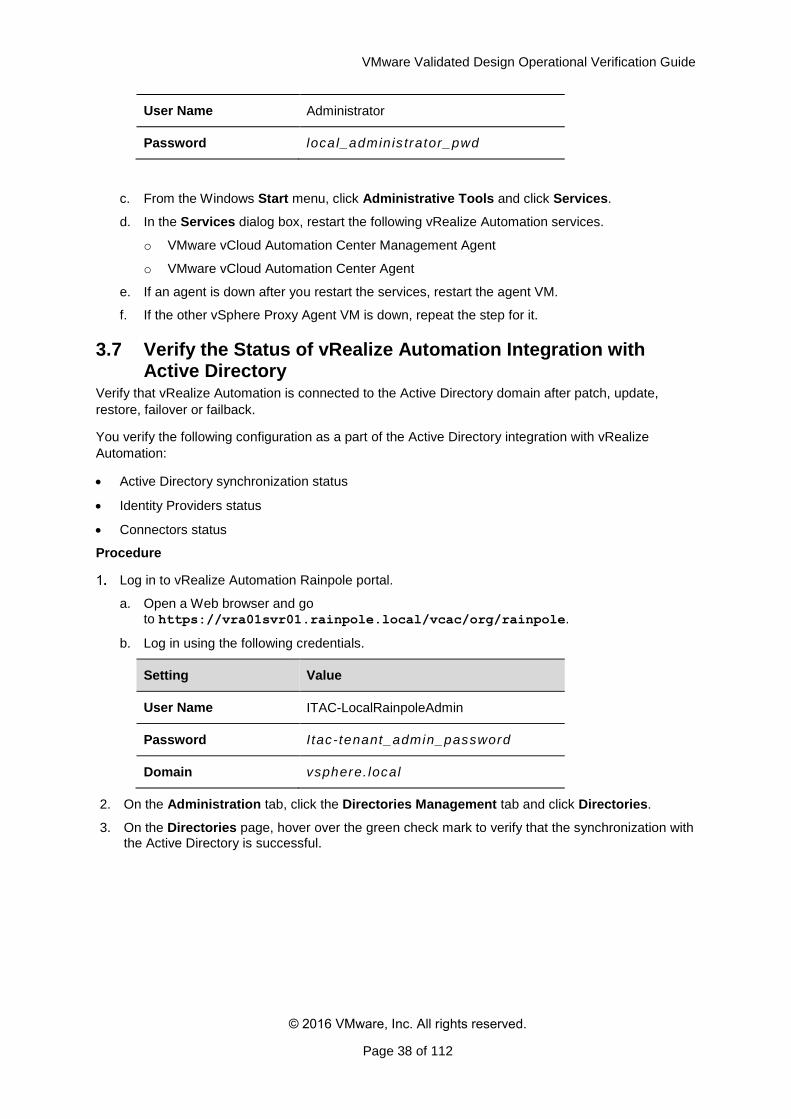
2. On the Administration tab, click the Directories Management tab and click Directories.
3. On the Directories page, hover over the green check mark to verify that the synchronization with the Active Directory is successful.
VMware Validated Design Operational Verification Guide
© 2016 VMware, Inc. All rights reserved.
Page 39 of 112
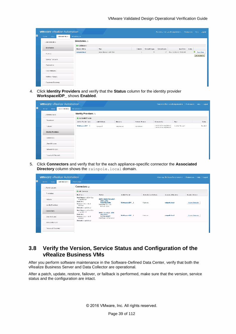
4. Click Identity Providers and verify that the Status column for the identity provider WorkspaceIDP_ shows Enabled.
5. Click Connectors and verify that for the each appliance-specific connector the Associated
Directory column shows the rainpole.local domain.
3.8 Verify the Version, Service Status and Configuration of the vRealize Business VMs
After you perform software maintenance in the Software-Defined Data Center, verify that both the vRealize Business Server and Data Collector are operational.
After a patch, update, restore, failover, or failback is performed, make sure that the version, service status and the configuration are intact.
VMware Validated Design Operational Verification Guide
© 2016 VMware, Inc. All rights reserved.
Page 40 of 112
Table 5. vRealize Business Virtual Appliances Details
Region vRealize Appliance
Virtual Appliance Management Interface (VAMI) URL
IP Address FQDN
Region A
vRealize Business Server
https://vra01bus01.rainpole.local:5480
192.168.11.66 vra01bus01.rainpole.local
vRealize Business Data Collector
https://vra01buc01.sfo01.rainpole.local:5480/
192.168.31.54 vra01buc01.sfo01.rainpole.local
Region B vRealize Business Data Collector
https://vra01buc51.lax01.rainpole.local:5480
192.168.32.54 vra01buc51.lax01.rainpole.local
Procedure
Verify the authentication of the vRealize Business Server virtual appliance.
a. Open a Web browser and go to https://vra01bus01.rainpole.local:5480/.
b. Log in using the following credentials.
Setting Value
User Name root
Password vrb_server_root_password
c. Log in to the vRealize Business Data Collectors vra01buc01.sfo01.rainpole.local
and vra01buc51.lax01.rainpole.local to verify the authentication.
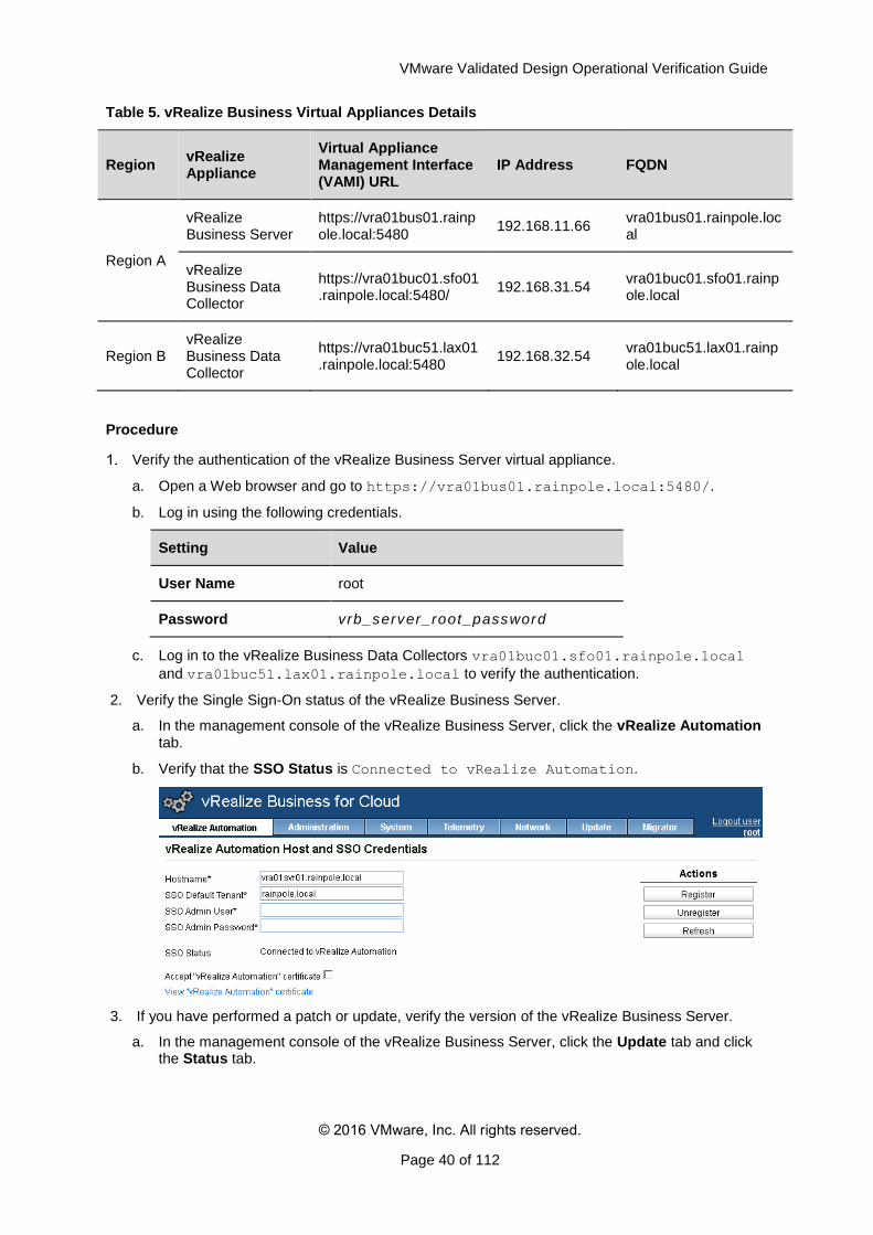
2. Verify the Single Sign-On status of the vRealize Business Server.
a. In the management console of the vRealize Business Server, click the vRealize Automation tab.
b. Verify that the SSO Status is Connected to vRealize Automation.
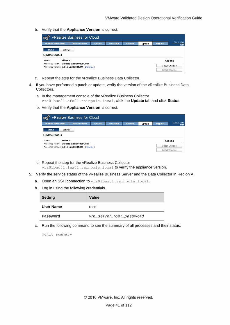
3. If you have performed a patch or update, verify the version of the vRealize Business Server.
a. In the management console of the vRealize Business Server, click the Update tab and click the Status tab.
VMware Validated Design Operational Verification Guide
© 2016 VMware, Inc. All rights reserved.
Page 41 of 112
b. Verify that the Appliance Version is correct.
c. Repeat the step for the vRealize Business Data Collector.
4. If you have performed a patch or update, verify the version of the vRealize Business Data Collectors.
a. In the management console of the vRealize Business Collector
vra01buc01.sfo01.rainpole.local, click the Update tab and click Status.
b. Verify that the Appliance Version is correct.
c. Repeat the step for the vRealize Business Collector
vra01buc51.lax01.rainpole.local to verify the appliance version.
5. Verify the service status of the vRealize Business Server and the Data Collector in Region A.
a. Open an SSH connection to vra01bus01.rainpole.local.
b. Log in using the following credentials.
Setting Value
User Name root
Password vrb_server_root_password
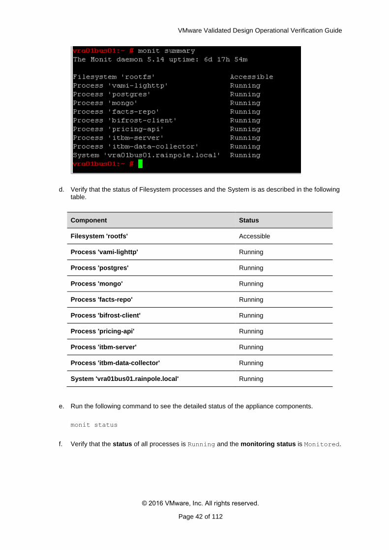
c. Run the following command to see the summary of all processes and their status. monit summary
VMware Validated Design Operational Verification Guide
© 2016 VMware, Inc. All rights reserved.
Page 42 of 112
d. Verify that the status of Filesystem processes and the System is as described in the following table.
Component Status
Filesystem 'rootfs' Accessible
Process 'vami-lighttp' Running
Process 'postgres' Running
Process 'mongo' Running
Process 'facts-repo' Running
Process 'bifrost-client' Running
Process 'pricing-api' Running
Process 'itbm-server' Running
Process 'itbm-data-collector' Running
System 'vra01bus01.rainpole.local' Running
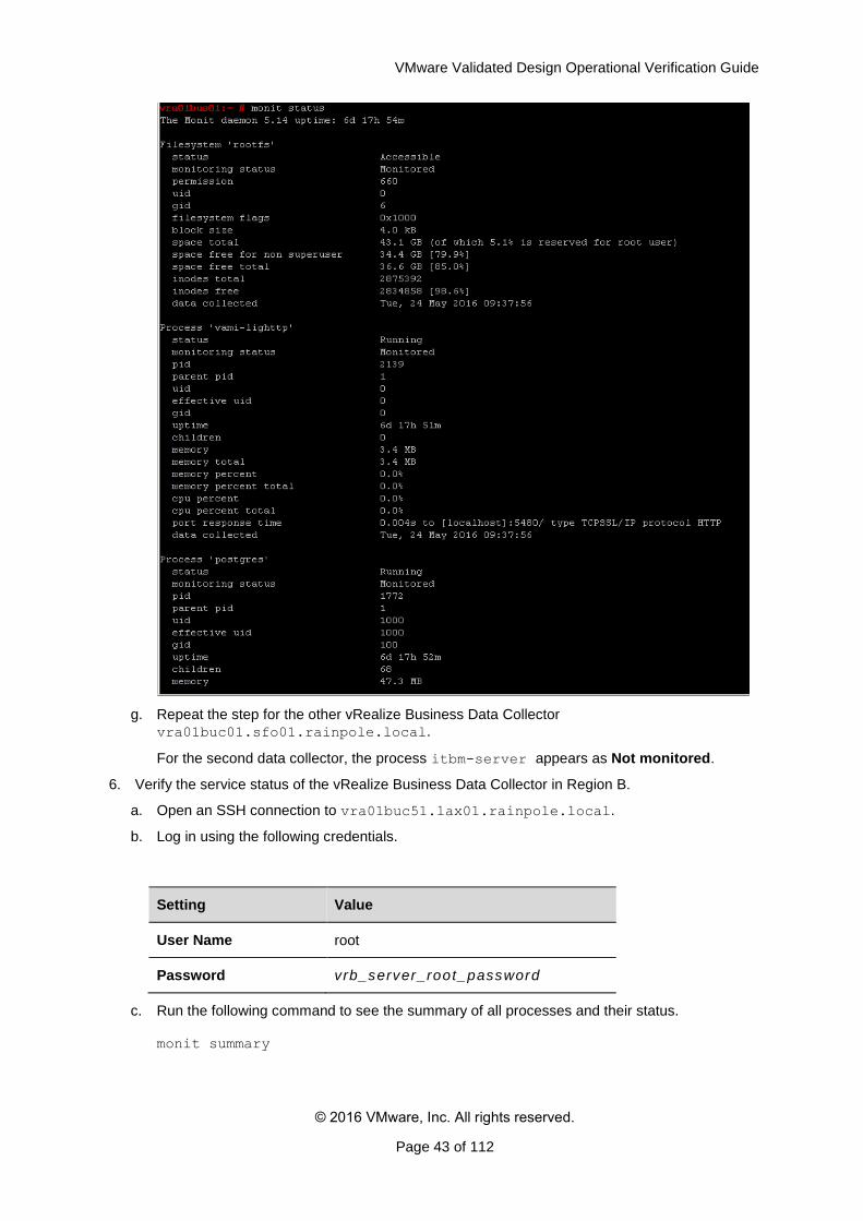
e. Run the following command to see the detailed status of the appliance components.
monit status
f. Verify that the status of all processes is Running and the monitoring status is Monitored.
VMware Validated Design Operational Verification Guide
© 2016 VMware, Inc. All rights reserved.
Page 43 of 112
g. Repeat the step for the other vRealize Business Data Collector
vra01buc01.sfo01.rainpole.local.
For the second data collector, the process itbm-server appears as Not monitored.
6. Verify the service status of the vRealize Business Data Collector in Region B.
a. Open an SSH connection to vra01buc51.lax01.rainpole.local.
b. Log in using the following credentials.
Setting Value
User Name root
Password vrb_server_root_password
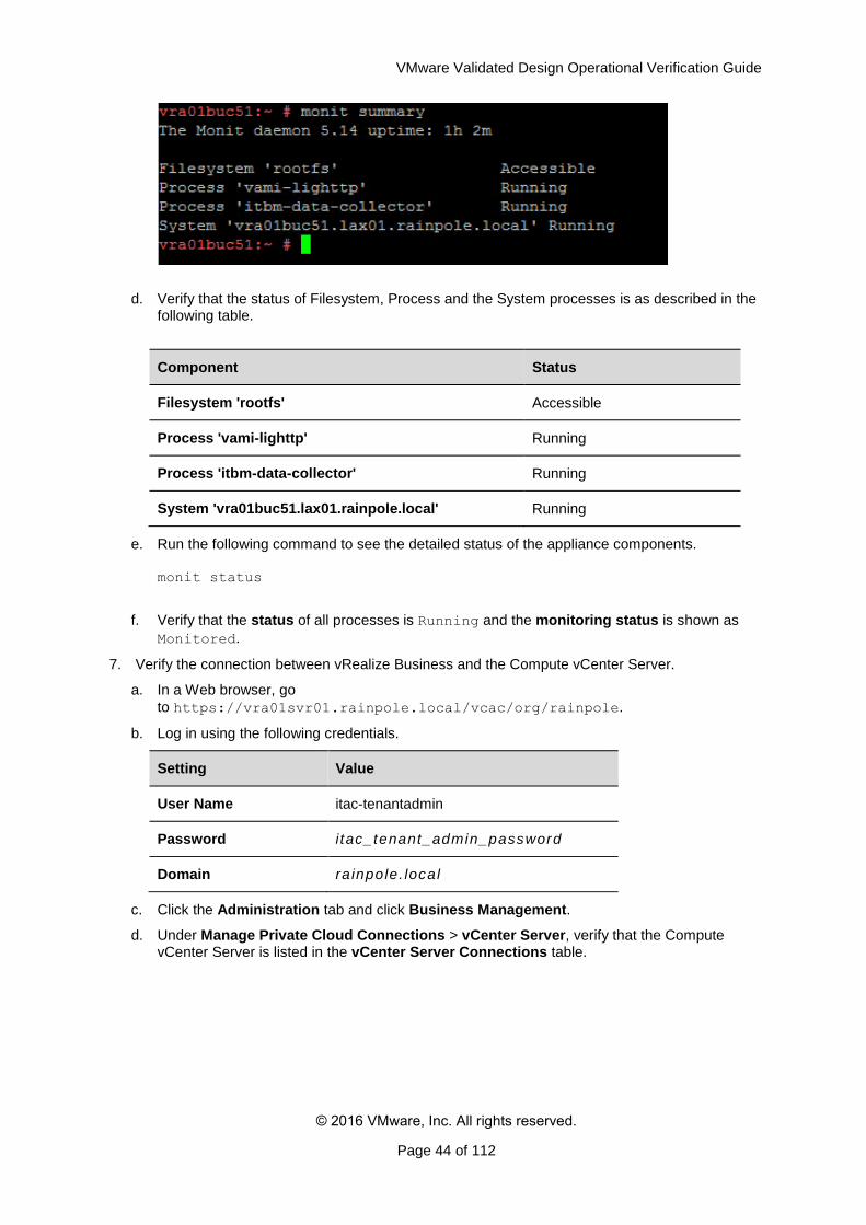
c. Run the following command to see the summary of all processes and their status. monit summary
VMware Validated Design Operational Verification Guide
© 2016 VMware, Inc. All rights reserved.
Page 44 of 112
d. Verify that the status of Filesystem, Process and the System processes is as described in the following table.
Component Status
Filesystem 'rootfs' Accessible
Process 'vami-lighttp' Running
Process 'itbm-data-collector' Running
System 'vra01buc51.lax01.rainpole.local' Running
e. Run the following command to see the detailed status of the appliance components. monit status
f. Verify that the status of all processes is Running and the monitoring status is shown as
Monitored.
7. Verify the connection between vRealize Business and the Compute vCenter Server.
a. In a Web browser, go
to https://vra01svr01.rainpole.local/vcac/org/rainpole.
b. Log in using the following credentials.
Setting Value
User Name itac-tenantadmin
Password i tac_tenant_admin_password
Domain ra inpole. local
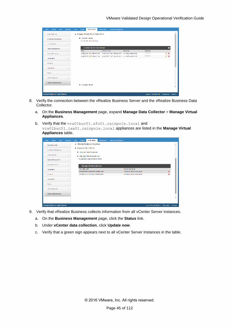
c. Click the Administration tab and click Business Management.
d. Under Manage Private Cloud Connections > vCenter Server, verify that the Compute vCenter Server is listed in the vCenter Server Connections table.
VMware Validated Design Operational Verification Guide
© 2016 VMware, Inc. All rights reserved.
Page 45 of 112
8. Verify the connection between the vRealize Business Server and the vRealize Business Data Collector.
a. On the Business Management page, expand Manage Data Collector > Manage Virtual Appliances.
b. Verify that the vra01buc01.sfo01.rainpole.local and
vra01buc51.lax01.rainpole.local appliances are listed in the Manage Virtual
Appliances table.
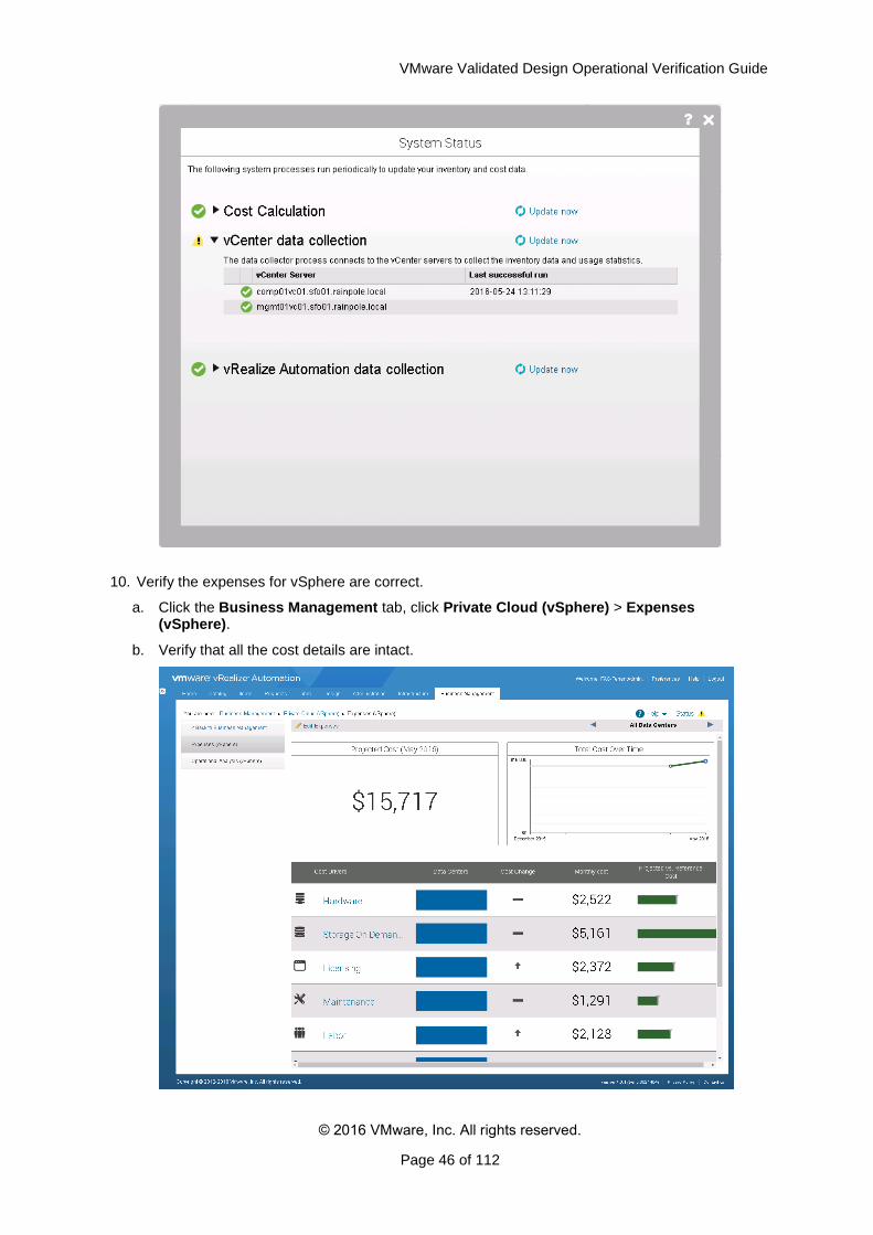
9. Verify that vRealize Business collects information from all vCenter Server instances.
a. On the Business Management page, click the Status link.
b. Under vCenter data collection, click Update now.
c. Verify that a green sign appears next to all vCenter Server Instances in the table.
VMware Validated Design Operational Verification Guide
© 2016 VMware, Inc. All rights reserved.
Page 46 of 112
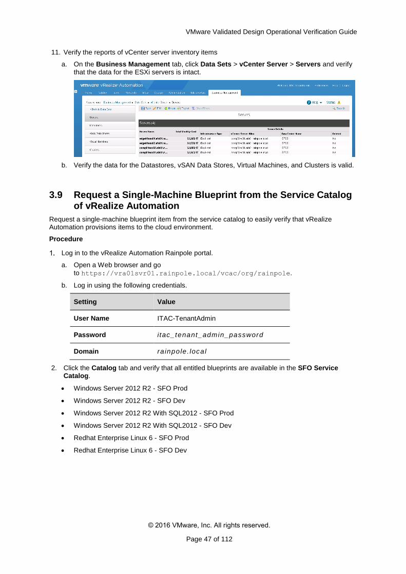
10. Verify the expenses for vSphere are correct.
a. Click the Business Management tab, click Private Cloud (vSphere) > Expenses (vSphere).
b. Verify that all the cost details are intact.
VMware Validated Design Operational Verification Guide
© 2016 VMware, Inc. All rights reserved.
Page 47 of 112
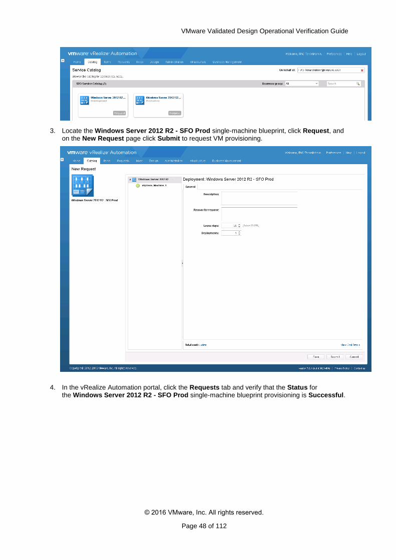
11. Verify the reports of vCenter server inventory items
a. On the Business Management tab, click Data Sets > vCenter Server > Servers and verify that the data for the ESXi servers is intact.
b. Verify the data for the Datastores, vSAN Data Stores, Virtual Machines, and Clusters is valid.
3.9 Request a Single-Machine Blueprint from the Service Catalog of vRealize Automation
Request a single-machine blueprint item from the service catalog to easily verify that vRealize Automation provisions items to the cloud environment.
Procedure
Log in to the vRealize Automation Rainpole portal.
a. Open a Web browser and go
to https://vra01svr01.rainpole.local/vcac/org/rainpole.
b. Log in using the following credentials.
Setting Value
User Name ITAC-TenantAdmin
Password i tac_tenant_admin_password
Domain ra inpole. local
2. Click the Catalog tab and verify that all entitled blueprints are available in the SFO Service Catalog.
Windows Server 2012 R2 - SFO Prod
Windows Server 2012 R2 - SFO Dev
Windows Server 2012 R2 With SQL2012 - SFO Prod
Windows Server 2012 R2 With SQL2012 - SFO Dev
Redhat Enterprise Linux 6 - SFO Prod
Redhat Enterprise Linux 6 - SFO Dev
VMware Validated Design Operational Verification Guide
© 2016 VMware, Inc. All rights reserved.
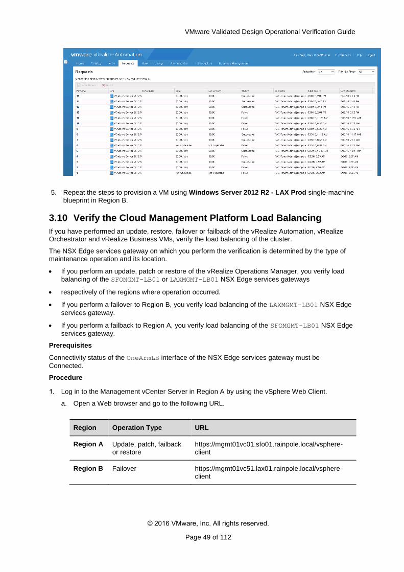
Page 48 of 112
3. Locate the Windows Server 2012 R2 - SFO Prod single-machine blueprint, click Request, and on the New Request page click Submit to request VM provisioning.
4. In the vRealize Automation portal, click the Requests tab and verify that the Status for the Windows Server 2012 R2 - SFO Prod single-machine blueprint provisioning is Successful.
VMware Validated Design Operational Verification Guide
© 2016 VMware, Inc. All rights reserved.
Page 49 of 112
5. Repeat the steps to provision a VM using Windows Server 2012 R2 - LAX Prod single-machine blueprint in Region B.
3.10 Verify the Cloud Management Platform Load Balancing
If you have performed an update, restore, failover or failback of the vRealize Automation, vRealize Orchestrator and vRealize Business VMs, verify the load balancing of the cluster.
The NSX Edge services gateway on which you perform the verification is determined by the type of maintenance operation and its location.
If you perform an update, patch or restore of the vRealize Operations Manager, you verify load
balancing of the SFOMGMT-LB01 or LAXMGMT-LB01 NSX Edge services gateways
respectively of the regions where operation occurred.
If you perform a failover to Region B, you verify load balancing of the LAXMGMT-LB01 NSX Edge
services gateway.
If you perform a failback to Region A, you verify load balancing of the SFOMGMT-LB01 NSX Edge
services gateway.
Prerequisites
Connectivity status of the OneArmLB interface of the NSX Edge services gateway must be
Connected.
Procedure
Log in to the Management vCenter Server in Region A by using the vSphere Web Client.
a. Open a Web browser and go to the following URL.
Region Operation Type URL
Region A Update, patch, failback or restore
https://mgmt01vc01.sfo01.rainpole.local/vsphere-client
Region B Failover https://mgmt01vc51.lax01.rainpole.local/vsphere-client
VMware Validated Design Operational Verification Guide
© 2016 VMware, Inc. All rights reserved.
Page 50 of 112
b. Log in using the following credentials.
Setting Value
User Name [email protected]
Password vsphere_admin_password
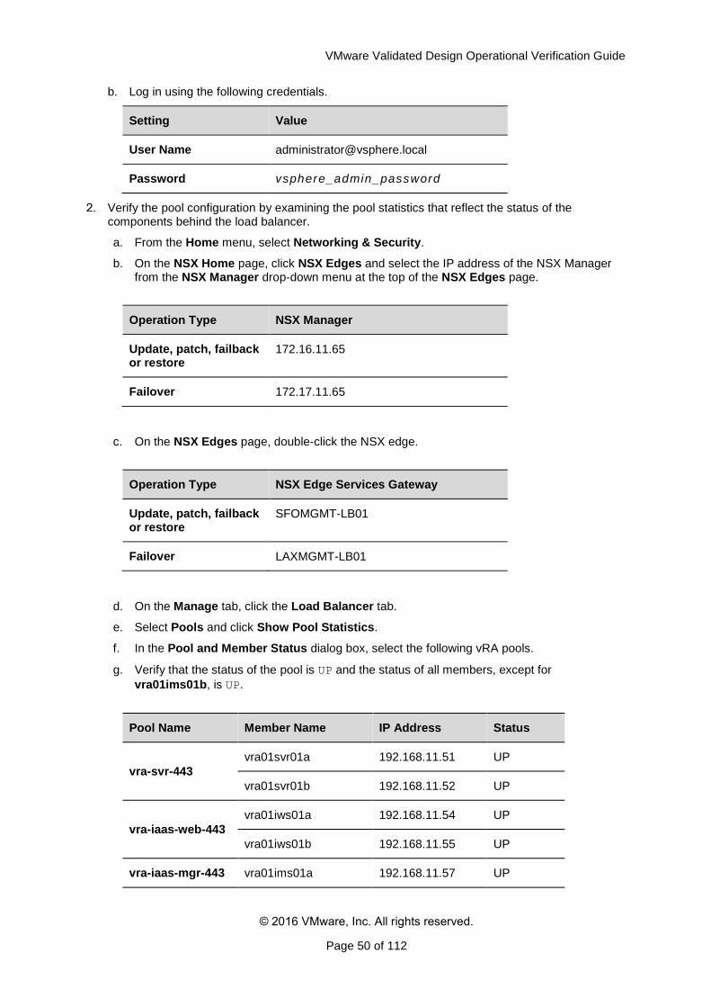
Verify the pool configuration by examining the pool statistics that reflect the status of the components behind the load balancer.
a. From the Home menu, select Networking & Security.
b. On the NSX Home page, click NSX Edges and select the IP address of the NSX Manager from the NSX Manager drop-down menu at the top of the NSX Edges page.
Operation Type NSX Manager
Update, patch, failback or restore
172.16.11.65
Failover 172.17.11.65
c. On the NSX Edges page, double-click the NSX edge.
Operation Type NSX Edge Services Gateway
Update, patch, failback or restore
SFOMGMT-LB01
Failover LAXMGMT-LB01
d. On the Manage tab, click the Load Balancer tab.
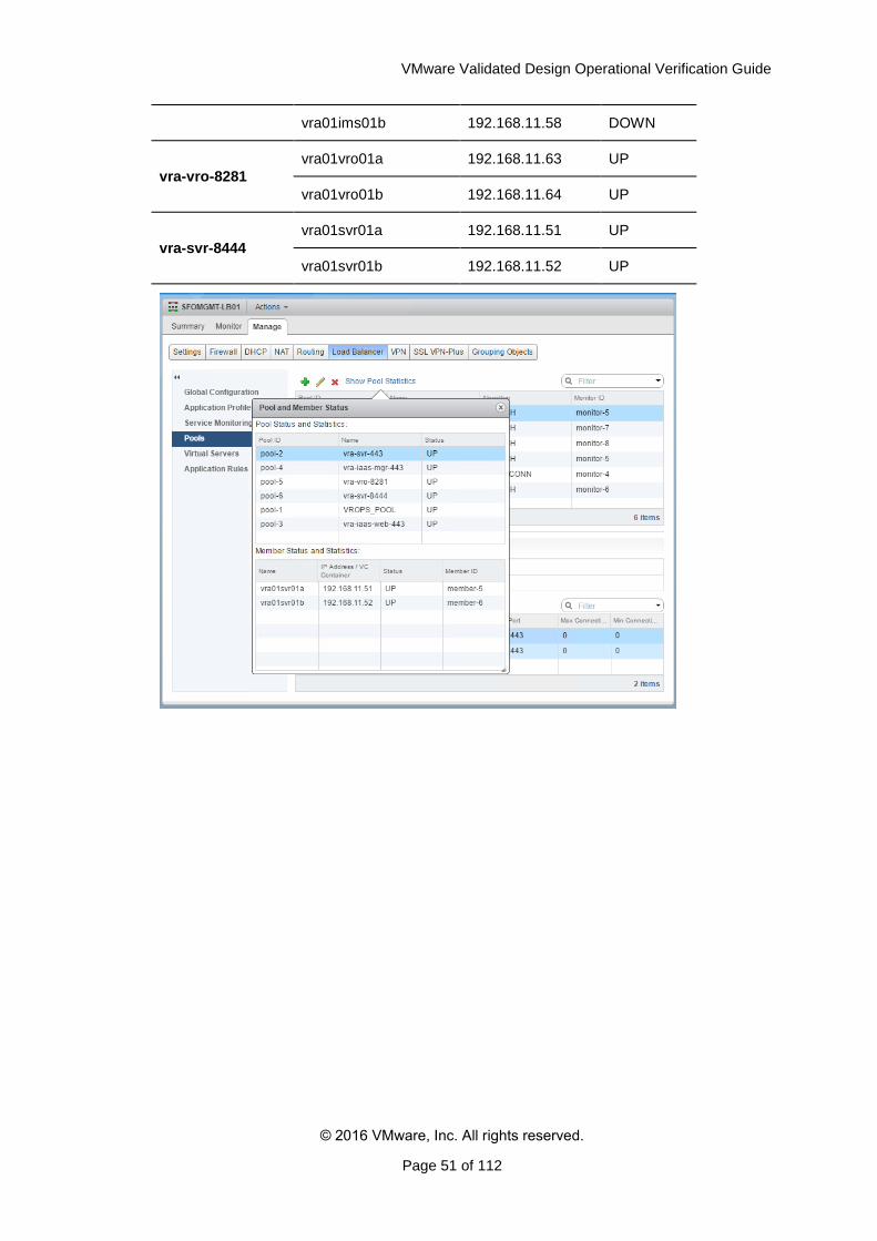
e. Select Pools and click Show Pool Statistics.
f. In the Pool and Member Status dialog box, select the following vRA pools.
g. Verify that the status of the pool is UP and the status of all members, except for
vra01ims01b, is UP.
Pool Name Member Name IP Address Status
vra-svr-443
vra01svr01a 192.168.11.51 UP
vra01svr01b 192.168.11.52 UP
vra-iaas-web-443
vra01iws01a 192.168.11.54 UP
vra01iws01b 192.168.11.55 UP
vra-iaas-mgr-443 vra01ims01a 192.168.11.57 UP
VMware Validated Design Operational Verification Guide
© 2016 VMware, Inc. All rights reserved.
Page 51 of 112
vra01ims01b 192.168.11.58 DOWN
vra-vro-8281
vra01vro01a 192.168.11.63 UP
vra01vro01b 192.168.11.64 UP
vra-svr-8444
vra01svr01a 192.168.11.51 UP
vra01svr01b 192.168.11.52 UP
VMware Validated Design Operational Verification Guide
© 2016 VMware, Inc. All rights reserved.
Page 52 of 112
4. Validate NSX for vSphere
After a maintenance like an update, upgrade, restore or recover, validate the NSX components and make sure they work as expected.
You validate the following NSX components:
NSX Manager instances for the management cluster and for the shared edge and compute cluster
NSX Controller nodes for the management cluster and for the shared edge and compute cluster
NSX Virtual Infrastructure Bundles (VIBs) installed on each host
Verify the Version, Service Status and Configuration of the NSX Manager Appliances
Verify the Status of NSX Controller Instances and Host Components
(Optional) Test VXLAN Connectivity of the Hosts in the Management Cluster
(Optional) Test VXLAN Connectivity of the Hosts in the Shared Edge and Compute Cluster
Verify the Status of NSX Firewall, Service Composer and Distributed Switches
Verify the Status of the NSX Edge Devices for North-South Routing
Verify the Status of the Universal Distributed Logical Router
Verify the Status of the NSX Load Balancer
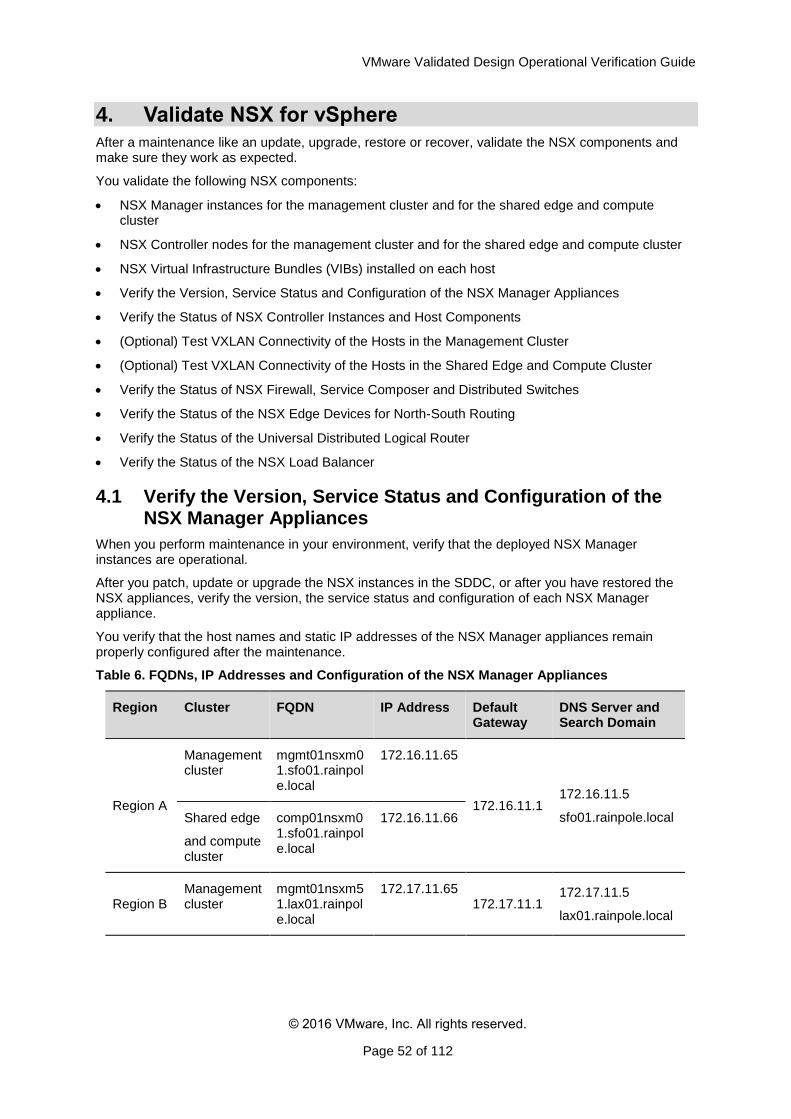
4.1 Verify the Version, Service Status and Configuration of the NSX Manager Appliances
When you perform maintenance in your environment, verify that the deployed NSX Manager instances are operational.
After you patch, update or upgrade the NSX instances in the SDDC, or after you have restored the NSX appliances, verify the version, the service status and configuration of each NSX Manager appliance.
You verify that the host names and static IP addresses of the NSX Manager appliances remain properly configured after the maintenance.
Table 6. FQDNs, IP Addresses and Configuration of the NSX Manager Appliances
Region Cluster FQDN IP Address Default Gateway
DNS Server and Search Domain
Region A
Management cluster
mgmt01nsxm01.sfo01.rainpole.local
172.16.11.65
172.16.11.1 172.16.11.5
sfo01.rainpole.local Shared edge
and compute cluster
comp01nsxm01.sfo01.rainpole.local
172.16.11.66
Region B Management cluster
mgmt01nsxm51.lax01.rainpole.local
172.17.11.65 172.17.11.1
172.17.11.5
lax01.rainpole.local
VMware Validated Design Operational Verification Guide
© 2016 VMware, Inc. All rights reserved.
Page 53 of 112
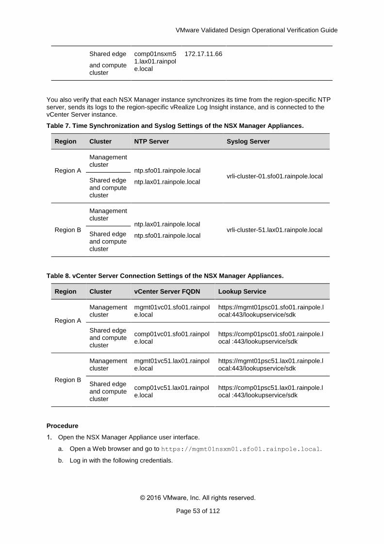
Shared edge
and compute cluster
comp01nsxm51.lax01.rainpole.local
172.17.11.66
You also verify that each NSX Manager instance synchronizes its time from the region-specific NTP server, sends its logs to the region-specific vRealize Log Insight instance, and is connected to the vCenter Server instance.
Table 7. Time Synchronization and Syslog Settings of the NSX Manager Appliances.
Region Cluster NTP Server Syslog Server
Region A
Management cluster
ntp.sfo01.rainpole.local
ntp.lax01.rainpole.local vrli-cluster-01.sfo01.rainpole.local
Shared edge and compute cluster
Region B
Management cluster
ntp.lax01.rainpole.local
ntp.sfo01.rainpole.local vrli-cluster-51.lax01.rainpole.local
Shared edge and compute cluster
Table 8. vCenter Server Connection Settings of the NSX Manager Appliances.
Region Cluster vCenter Server FQDN Lookup Service
Region A
Management cluster
mgmt01vc01.sfo01.rainpole.local
https://mgmt01psc01.sfo01.rainpole.local:443/lookupservice/sdk
Shared edge and compute cluster
comp01vc01.sfo01.rainpole.local
https://comp01psc01.sfo01.rainpole.local :443/lookupservice/sdk
Region B
Management cluster
mgmt01vc51.lax01.rainpole.local
https://mgmt01psc51.lax01.rainpole.local:443/lookupservice/sdk
Shared edge and compute cluster
comp01vc51.lax01.rainpole.local
https://comp01psc51.lax01.rainpole.local :443/lookupservice/sdk
Procedure
Open the NSX Manager Appliance user interface.
a. Open a Web browser and go to https://mgmt01nsxm01.sfo01.rainpole.local.
b. Log in with the following credentials.
VMware Validated Design Operational Verification Guide
© 2016 VMware, Inc. All rights reserved.
Page 54 of 112
Setting Value
User Name admin
Password mngnsx_admin_regA_password
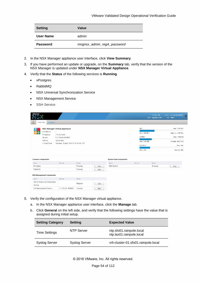
In the NSX Manager appliance user interface, click View Summary.
If you have performed an update or upgrade, on the Summary tab, verify that the version of the NSX Manager is updated under NSX Manager Virtual Appliance.
Verify that the Status of the following services is Running.
vPostgres
RabbitMQ
NSX Universal Synchronization Service
NSX Management Service
SSH Service
Verify the configuration of the NSX Manager virtual appliance.
a. In the NSX Manager appliance user interface, click the Manage tab.
b. Click General on the left side, and verify that the following settings have the value that is assigned during initial setup.
Setting Category Setting Expected Value
Time Settings NTP Server ntp.sfo01.rainpole.local
ntp.lax01.rainpole.local
Syslog Server Syslog Server vrli-cluster-01.sfo01.rainpole.local
VMware Validated Design Operational Verification Guide
© 2016 VMware, Inc. All rights reserved.
Page 55 of 112
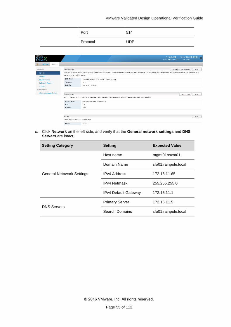
Port 514
Protocol UDP
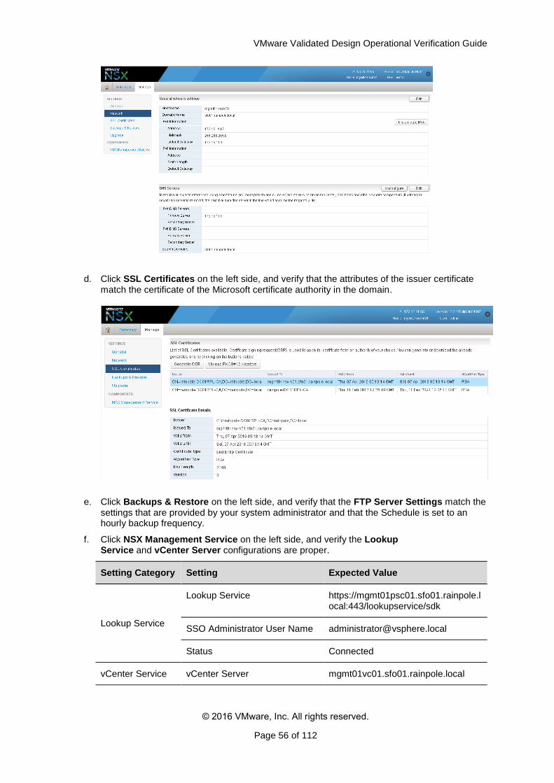
c. Click Network on the left side, and verify that the General network settings and DNS Servers are intact.
Setting Category Setting Expected Value
General Netowork Settings
Host name mgmt01nsxm01
Domain Name sfo01.rainpole.local
IPv4 Address 172.16.11.65
IPv4 Netmask 255.255.255.0
IPv4 Default Gateway 172.16.11.1
DNS Servers
Primary Server 172.16.11.5
Search Domains sfo01.rainpole.local
VMware Validated Design Operational Verification Guide
© 2016 VMware, Inc. All rights reserved.
Page 56 of 112
d. Click SSL Certificates on the left side, and verify that the attributes of the issuer certificate match the certificate of the Microsoft certificate authority in the domain.
e. Click Backups & Restore on the left side, and verify that the FTP Server Settings match the settings that are provided by your system administrator and that the Schedule is set to an hourly backup frequency.
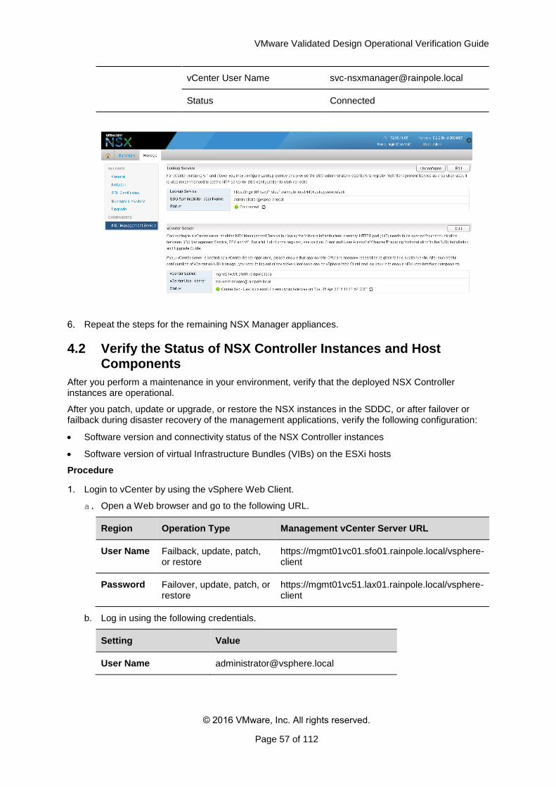
f. Click NSX Management Service on the left side, and verify the Lookup Service and vCenter Server configurations are proper.
Setting Category Setting Expected Value
Lookup Service
Lookup Service https://mgmt01psc01.sfo01.rainpole.local:443/lookupservice/sdk
SSO Administrator User Name [email protected]
Status Connected
vCenter Service vCenter Server mgmt01vc01.sfo01.rainpole.local
VMware Validated Design Operational Verification Guide
© 2016 VMware, Inc. All rights reserved.
Page 57 of 112
vCenter User Name [email protected]
Status Connected
Repeat the steps for the remaining NSX Manager appliances.
4.2 Verify the Status of NSX Controller Instances and Host Components
After you perform a maintenance in your environment, verify that the deployed NSX Controller instances are operational.
After you patch, update or upgrade, or restore the NSX instances in the SDDC, or after failover or failback during disaster recovery of the management applications, verify the following configuration:
Software version and connectivity status of the NSX Controller instances
Software version of virtual Infrastructure Bundles (VIBs) on the ESXi hosts
Procedure
Login to vCenter by using the vSphere Web Client.
a. Open a Web browser and go to the following URL.
Region Operation Type Management vCenter Server URL
User Name Failback, update, patch, or restore
https://mgmt01vc01.sfo01.rainpole.local/vsphere-client
Password Failover, update, patch, or restore
https://mgmt01vc51.lax01.rainpole.local/vsphere-client
b. Log in using the following credentials.
Setting Value
User Name [email protected]
VMware Validated Design Operational Verification Guide
© 2016 VMware, Inc. All rights reserved.
Page 58 of 112
Password vsphere_admin_password
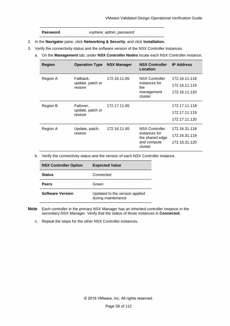
2. In the Navigator pane, click Networking & Security, and click Installation.
3. Verify the connectivity status and the software version of the NSX Controller instances.
a. On the Management tab, under NSX Controller Nodes locate each NSX Controller instance.
Region Operation Type NSX Manager NSX Controller Location
IP Address
Region A Failback, update, patch or restore
172.16.11.65 NSX Controller instances for the management cluster
172.16.11.118
172.16.11.119
172.16.11.120
Region B Failover, update, patch or restore
172.17.11.65 172.17.11.118
172.17.11.119
172.17.11.120
Region A Update, patch, restore
172.16.11.65 NSX Controller instances for the shared edge and compute cluster
172.16.31.118
172.16.31.119
172.16.31.120
b. Verify the connectivity status and the version of each NSX Controller instance.
NSX Controller Option Expected Value
Status Connected
Peers Green
Software Version Updated to the version applied during maintenance
Note Each controller in the primary NSX Manager has an inherited controller instance in the secondary NSX Manager. Verify that the status of those instances is Connected.
c. Repeat the steps for the other NSX Controller instances.
VMware Validated Design Operational Verification Guide
© 2016 VMware, Inc. All rights reserved.
Page 59 of 112
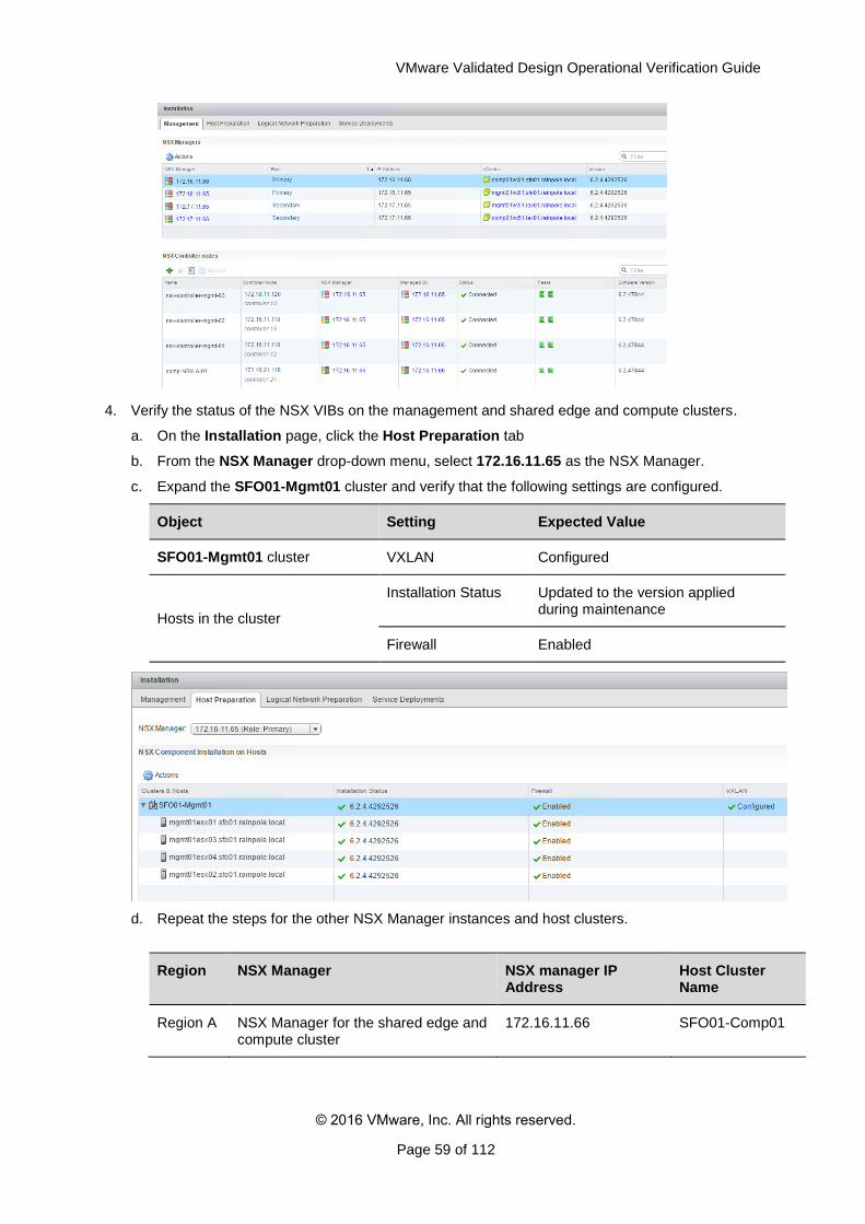
4. Verify the status of the NSX VIBs on the management and shared edge and compute clusters.
a. On the Installation page, click the Host Preparation tab
b. From the NSX Manager drop-down menu, select 172.16.11.65 as the NSX Manager.
c. Expand the SFO01-Mgmt01 cluster and verify that the following settings are configured.
Object Setting Expected Value
SFO01-Mgmt01 cluster VXLAN Configured
Hosts in the cluster
Installation Status Updated to the version applied during maintenance
Firewall Enabled
d. Repeat the steps for the other NSX Manager instances and host clusters.
Region NSX Manager NSX manager IP Address
Host Cluster Name
Region A NSX Manager for the shared edge and compute cluster
172.16.11.66 SFO01-Comp01
VMware Validated Design Operational Verification Guide
© 2016 VMware, Inc. All rights reserved.
Page 60 of 112
Region B NSX Controller instances for the management cluster
172.17.11.65 LAX01-Mgmt01
172.17.11.66 LAX01-Comp01
5. (Optional) Confirm that the NSX VIBs on the hosts are updated.
a. Open an SSH connection to a host in each cluster with user name root and password esxi_root_user_password .
Cluster Host
SFO01-Mgmt01 mgmt01esx01.sfo01.rainpole.local
SFO01-Comp01 comp01esx01.sfo01.rainpole.local
LAX01-Mgmt01 mgmt01esx51.lax01.rainpole.local
LAX01-Comp01 comp01esx51.sfo01.rainpole.local
b. Run the following console command
esxcli software vib list | grep esx
c. Make sure that the following VIBs have been updated to the expected version.
o esx-vsip
o esx-vxlan
d. Verify that the User World Agent (UWA) in the ESXi host is running.
/etc/init.d/netcpad status
e. Repeat the steps for a host in each of the other clusters in the SDDC.
4.3 (Optional) Test VXLAN Connectivity of the Hosts in the Management Cluster
After you verify that the NSX components are operational, perform a ping test to check whether two hosts on the VXLAN transport network for the management cluster can reach each other.
You create a logical switch on the VXLAN network in Region A and use that switch for the ping between the hosts in both regions.
Table 9. Test Parameters for VXLAN Host Connectivity
NSX Manager IP Address Source Host Destination Host
NSX Manager for the management cluster in Region A
172.16.11.65 mgmt01esx04.sfo01.rainpole.local
mgmt01esx01.sfo01.rainpole.local
NSX Manager for the management cluster in Region B
172.17.11.65 mgmt01esx54.lax01.rainpole.local
mgmt01esx51.lax01.rainpole.local
Procedure
Login to vCenter by using the vSphere Web Client.

VMware Validated Design Operational Verification Guide
© 2016 VMware, Inc. All rights reserved.
Page 61 of 112
a. Open a Web browser and go to
https://mgmt01vc01.sfo01.rainpole.local/vsphere-client.
b. Log in using the following credentials.
Setting Value
User Name [email protected]
Password vsphere_admin_password
Create a logical switch to test the logical network.
a. In the Navigator pane, click Networking & Security and click Logical Switches.
b. On the Logical Switches page, select 172.16.11.65 from the NSX Manager drop-down menu.
c. Click the New Logical Switch icon.
d. In the New Logical Switch dialog box, enter the following settings, and click OK.
Setting Value
Name mgmt01-logical-switch
Transport Zone Mgmt Transport Zone
Replication mode Hybrid
Enable IP Discovery Selected
Enable MAC Learning Deselected
Use the ping monitor to test connectivity in Region A.
VMware Validated Design Operational Verification Guide
© 2016 VMware, Inc. All rights reserved.
Page 62 of 112
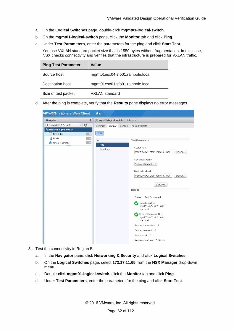
a. On the Logical Switches page, double-click mgmt01-logical-switch.
b. On the mgmt01-logical-switch page, click the Monitor tab and click Ping.
c. Under Test Parameters, enter the parameters for the ping and click Start Test.
You use VXLAN standard packet size that is 1550 bytes without fragmentation. In this case, NSX checks connectivity and verifies that the infrastructure is prepared for VXLAN traffic.
Ping Test Parameter Value
Source host mgmt01esx04.sfo01.rainpole.local
Destination host mgmt01esx01.sfo01.rainpole.local
Size of test packet VXLAN standard
d. After the ping is complete, verify that the Results pane displays no error messages.
Test the connectivity in Region B.
a. In the Navigator pane, click Networking & Security and click Logical Switches.
b. On the Logical Switches page, select 172.17.11.65 from the NSX Manager drop-down menu.
c. Double-click mgmt01-logical-switch, click the Monitor tab and click Ping.
d. Under Test Parameters, enter the parameters for the ping and click Start Test.
VMware Validated Design Operational Verification Guide
© 2016 VMware, Inc. All rights reserved.
Page 63 of 112
Ping Test Parameter Value
Source host mgmt01esx54.lax01.rainpole.local
Destination host mgmt01esx51.lax01.rainpole.local
Size of test packet VXLAN standard
e. After the ping is complete, verify that the Results pane displays no error messages.
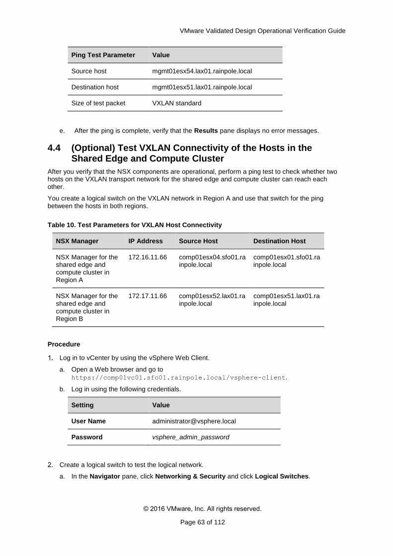
4.4 (Optional) Test VXLAN Connectivity of the Hosts in the Shared Edge and Compute Cluster
After you verify that the NSX components are operational, perform a ping test to check whether two hosts on the VXLAN transport network for the shared edge and compute cluster can reach each other.
You create a logical switch on the VXLAN network in Region A and use that switch for the ping between the hosts in both regions.
Table 10. Test Parameters for VXLAN Host Connectivity
NSX Manager IP Address Source Host Destination Host
NSX Manager for the shared edge and compute cluster in Region A
172.16.11.66 comp01esx04.sfo01.rainpole.local
comp01esx01.sfo01.rainpole.local
NSX Manager for the shared edge and compute cluster in Region B
172.17.11.66 comp01esx52.lax01.rainpole.local
comp01esx51.lax01.rainpole.local
Procedure
Log in to vCenter by using the vSphere Web Client.
a. Open a Web browser and go to
https://comp01vc01.sfo01.rainpole.local/vsphere-client.
b. Log in using the following credentials.
Setting Value
User Name [email protected]
Password vsphere_admin_password
Create a logical switch to test the logical network.
a. In the Navigator pane, click Networking & Security and click Logical Switches.
VMware Validated Design Operational Verification Guide
© 2016 VMware, Inc. All rights reserved.
Page 64 of 112
b. On the Logical Switches page, select 172.16.11.66 from the NSX Manager drop-down menu.
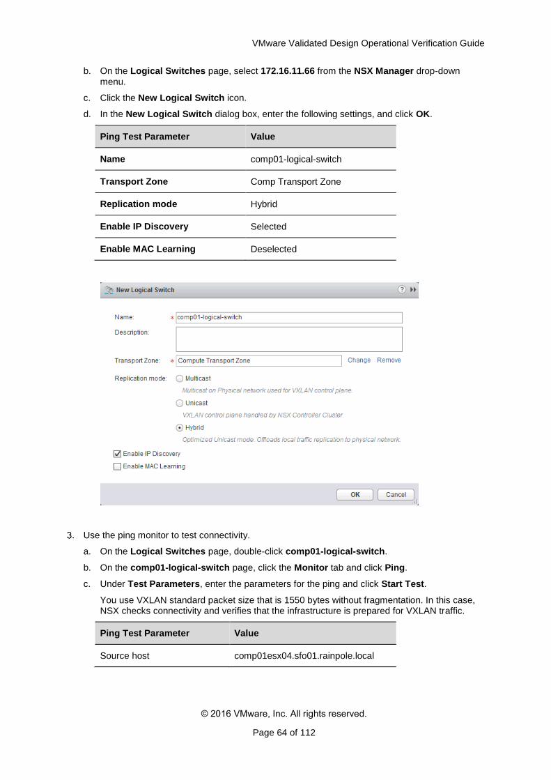
c. Click the New Logical Switch icon.
d. In the New Logical Switch dialog box, enter the following settings, and click OK.
Ping Test Parameter Value
Name comp01-logical-switch
Transport Zone Comp Transport Zone
Replication mode Hybrid
Enable IP Discovery Selected
Enable MAC Learning Deselected
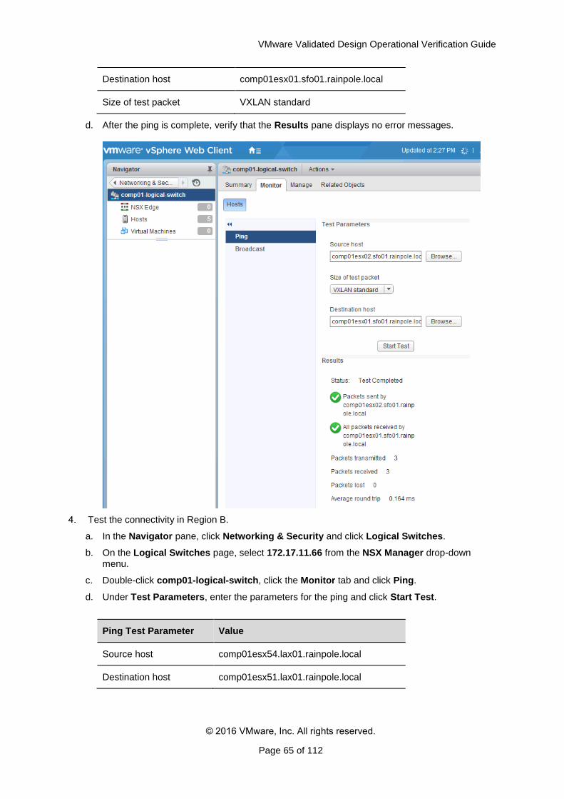
Use the ping monitor to test connectivity.
a. On the Logical Switches page, double-click comp01-logical-switch.
b. On the comp01-logical-switch page, click the Monitor tab and click Ping.
c. Under Test Parameters, enter the parameters for the ping and click Start Test.
You use VXLAN standard packet size that is 1550 bytes without fragmentation. In this case, NSX checks connectivity and verifies that the infrastructure is prepared for VXLAN traffic.
Ping Test Parameter Value
Source host comp01esx04.sfo01.rainpole.local
VMware Validated Design Operational Verification Guide
© 2016 VMware, Inc. All rights reserved.
Page 65 of 112
Destination host comp01esx01.sfo01.rainpole.local
Size of test packet VXLAN standard
d. After the ping is complete, verify that the Results pane displays no error messages.
Test the connectivity in Region B.
a. In the Navigator pane, click Networking & Security and click Logical Switches.
b. On the Logical Switches page, select 172.17.11.66 from the NSX Manager drop-down menu.
c. Double-click comp01-logical-switch, click the Monitor tab and click Ping.
d. Under Test Parameters, enter the parameters for the ping and click Start Test.
Ping Test Parameter Value
Source host comp01esx54.lax01.rainpole.local
Destination host comp01esx51.lax01.rainpole.local
VMware Validated Design Operational Verification Guide
© 2016 VMware, Inc. All rights reserved.
Page 66 of 112
Size of test packet VXLAN standard
e. After the ping is complete, verify that the Results pane displays no error messages.
4.5 Verify the Status of NSX Firewall, Service Composer and Distributed Switches
After you perform software maintenance in your environment, verify that the NSX firewall, service composer, and distributed switches configurations are intact.
After you patch, update or upgrade the NSX instances, or after you have restored the NSX appliances, verify the NSX firewall, service composer, and distributed switches configuration of each NSX Manager appliance.
Table 11. NSX Manager Instances
Region NSX Manager Instance IP Address
Region A
NSX Manager for the management cluster 172.16.11.65
NSX Manager for the shared edge and compute cluster 172.16.11.66
Region B NSX Manager for the management cluster 172.17.11.65
NSX Manager for the shared edge and compute cluster 172.17.11.66
Procedure
Login to vCenter by using the vSphere Web Client.
a. Open a Web browser and go to
https://mgmt01vc01.sfo01.rainpole.local/vsphere-client.
b. Log in using the following credentials.
Setting Value
User Name [email protected]
Password vsphere_admin_password
2. Verify the status of the NSX firewall.
a. In the Navigator pane, click Networking & Security,
b. Under Networking & Security, click Firewall.
c. Select 172.16.11.65 from the NSX Manager drop-down menu.
d. Verify that the Firewall configurations are intact.
e. Repeat the step for the remaining NSX Manager instances.
3. Verify the status of the service composer.
a. In the Navigator pane, click Networking & Security.
b. Under Networking & Security, click Service Composer.
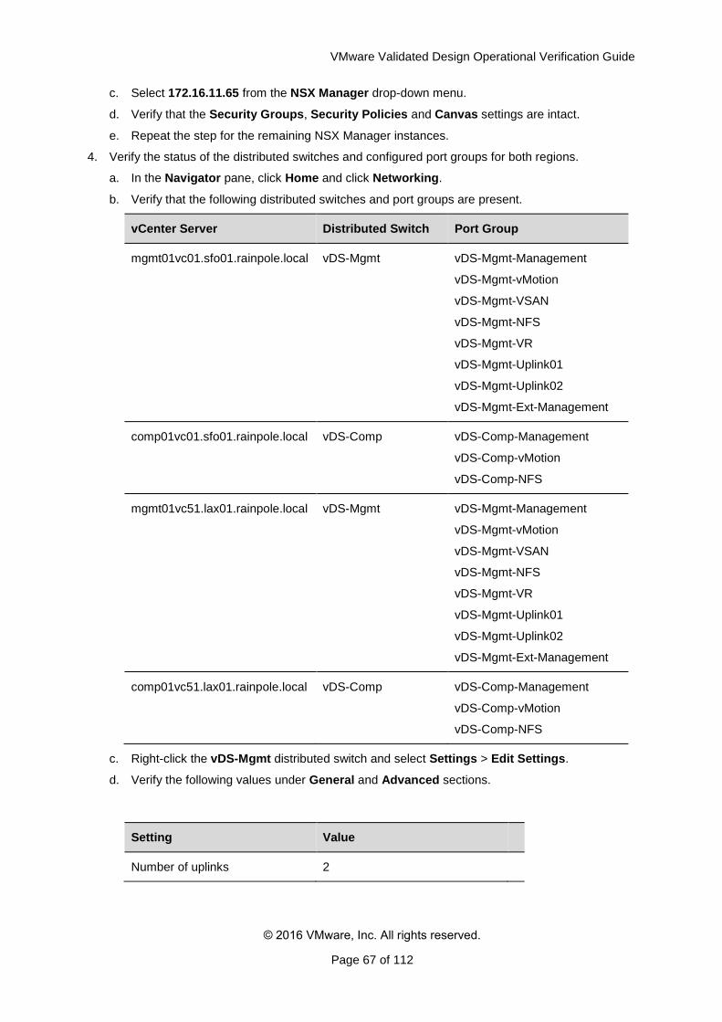
VMware Validated Design Operational Verification Guide
© 2016 VMware, Inc. All rights reserved.
Page 67 of 112
c. Select 172.16.11.65 from the NSX Manager drop-down menu.
d. Verify that the Security Groups, Security Policies and Canvas settings are intact.
e. Repeat the step for the remaining NSX Manager instances.
4. Verify the status of the distributed switches and configured port groups for both regions.
a. In the Navigator pane, click Home and click Networking.
b. Verify that the following distributed switches and port groups are present.
vCenter Server Distributed Switch Port Group
mgmt01vc01.sfo01.rainpole.local vDS-Mgmt vDS-Mgmt-Management
vDS-Mgmt-vMotion
vDS-Mgmt-VSAN
vDS-Mgmt-NFS
vDS-Mgmt-VR
vDS-Mgmt-Uplink01
vDS-Mgmt-Uplink02
vDS-Mgmt-Ext-Management
comp01vc01.sfo01.rainpole.local vDS-Comp vDS-Comp-Management
vDS-Comp-vMotion
vDS-Comp-NFS
mgmt01vc51.lax01.rainpole.local vDS-Mgmt vDS-Mgmt-Management
vDS-Mgmt-vMotion
vDS-Mgmt-VSAN
vDS-Mgmt-NFS
vDS-Mgmt-VR
vDS-Mgmt-Uplink01
vDS-Mgmt-Uplink02
vDS-Mgmt-Ext-Management
comp01vc51.lax01.rainpole.local vDS-Comp vDS-Comp-Management
vDS-Comp-vMotion
vDS-Comp-NFS
c. Right-click the vDS-Mgmt distributed switch and select Settings > Edit Settings.
d. Verify the following values under General and Advanced sections.
Setting Value
Number of uplinks 2
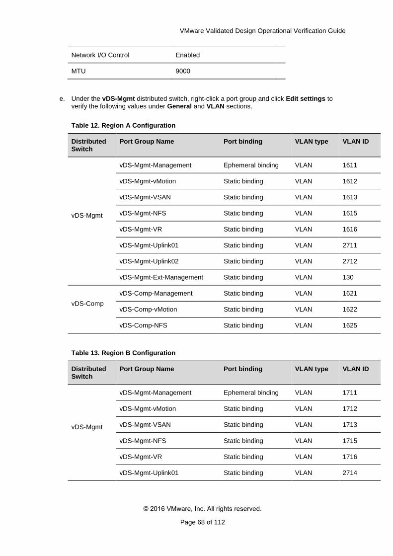
VMware Validated Design Operational Verification Guide
© 2016 VMware, Inc. All rights reserved.
Page 68 of 112
Network I/O Control Enabled
MTU 9000
e. Under the vDS-Mgmt distributed switch, right-click a port group and click Edit settings to verify the following values under General and VLAN sections.
Table 12. Region A Configuration
Distributed Switch
Port Group Name Port binding VLAN type VLAN ID
vDS-Mgmt
vDS-Mgmt-Management Ephemeral binding VLAN 1611
vDS-Mgmt-vMotion Static binding VLAN 1612
vDS-Mgmt-VSAN Static binding VLAN 1613
vDS-Mgmt-NFS Static binding VLAN 1615
vDS-Mgmt-VR Static binding VLAN 1616
vDS-Mgmt-Uplink01 Static binding VLAN 2711
vDS-Mgmt-Uplink02 Static binding VLAN 2712
vDS-Mgmt-Ext-Management Static binding VLAN 130
vDS-Comp
vDS-Comp-Management Static binding VLAN 1621
vDS-Comp-vMotion Static binding VLAN 1622
vDS-Comp-NFS Static binding VLAN 1625
Table 13. Region B Configuration
Distributed Switch
Port Group Name Port binding VLAN type VLAN ID
vDS-Mgmt
vDS-Mgmt-Management Ephemeral binding VLAN 1711
vDS-Mgmt-vMotion Static binding VLAN 1712
vDS-Mgmt-VSAN Static binding VLAN 1713
vDS-Mgmt-NFS Static binding VLAN 1715
vDS-Mgmt-VR Static binding VLAN 1716
vDS-Mgmt-Uplink01 Static binding VLAN 2714
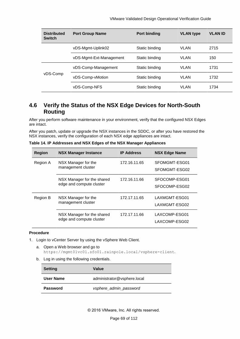
VMware Validated Design Operational Verification Guide
© 2016 VMware, Inc. All rights reserved.
Page 69 of 112
Distributed Switch
Port Group Name Port binding VLAN type VLAN ID
vDS-Mgmt-Uplink02 Static binding VLAN 2715
vDS-Mgmt-Ext-Management Static binding VLAN 150
vDS-Comp
vDS-Comp-Management Static binding VLAN 1731
vDS-Comp-vMotion Static binding VLAN 1732
vDS-Comp-NFS Static binding VLAN 1734
4.6 Verify the Status of the NSX Edge Devices for North-South Routing
After you perform software maintenance in your environment, verify that the configured NSX Edges are intact.
After you patch, update or upgrade the NSX instances in the SDDC, or after you have restored the NSX instances, verify the configuration of each NSX edge appliances are intact.
Table 14. IP Addresses and NSX Edges of the NSX Manager Appliances
Region NSX Manager Instance IP Address NSX Edge Name
Region A NSX Manager for the management cluster
172.16.11.65 SFOMGMT-ESG01
SFOMGMT-ESG02
NSX Manager for the shared edge and compute cluster
172.16.11.66 SFOCOMP-ESG01
SFOCOMP-ESG02
Region B NSX Manager for the management cluster
172.17.11.65 LAXMGMT-ESG01
LAXMGMT-ESG02
NSX Manager for the shared edge and compute cluster
172.17.11.66 LAXCOMP-ESG01
LAXCOMP-ESG02
Procedure
Login to vCenter Server by using the vSphere Web Client.
a. Open a Web browser and go to
https://mgmt01vc01.sfo01.rainpole.local/vsphere-client.
b. Log in using the following credentials.
Setting Value
User Name [email protected]
Password vsphere_admin_password
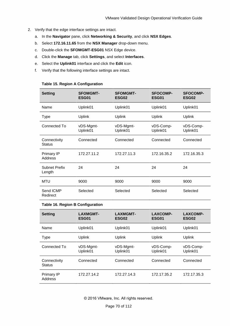
VMware Validated Design Operational Verification Guide
© 2016 VMware, Inc. All rights reserved.
Page 70 of 112
2. Verify that the edge interface settings are intact.
a. In the Navigator pane, click Networking & Security, and click NSX Edges.
b. Select 172.16.11.65 from the NSX Manager drop-down menu.
c. Double-click the SFOMGMT-ESG01 NSX Edge device.
d. Click the Manage tab, click Settings, and select Interfaces.
e. Select the Uplink01 interface and click the Edit icon.
f. Verify that the following interface settings are intact.
Table 15. Region A Configuration
Setting SFOMGMT-ESG01
SFOMGMT-ESG02
SFOCOMP-ESG01
SFOCOMP-ESG02
Name Uplink01 Uplink01 Uplink01 Uplink01
Type Uplink Uplink Uplink Uplink
Connected To vDS-Mgmt-Uplink01
vDS-Mgmt-Uplink01
vDS-Comp-Uplink01
vDS-Comp-Uplink01
Connectivity Status
Connected Connected Connected Connected
Primary IP Address
172.27.11.2 172.27.11.3 172.16.35.2 172.16.35.3
Subnet Prefix Length
24 24 24 24
MTU 9000 9000 9000 9000
Send ICMP Redirect
Selected Selected Selected Selected
Table 16. Region B Configuration
Setting LAXMGMT-ESG01
LAXMGMT-ESG02
LAXCOMP-ESG01
LAXCOMP-ESG02
Name Uplink01 Uplink01 Uplink01 Uplink01
Type Uplink Uplink Uplink Uplink
Connected To vDS-Mgmt-Uplink01
vDS-Mgmt-Uplink01
vDS-Comp-Uplink01
vDS-Comp-Uplink01
Connectivity Status
Connected Connected Connected Connected
Primary IP Address
172.27.14.2 172.27.14.3 172.17.35.2 172.17.35.3
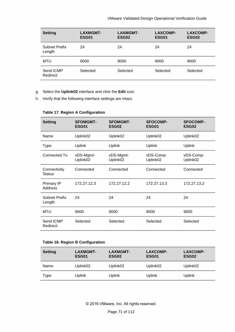
VMware Validated Design Operational Verification Guide
© 2016 VMware, Inc. All rights reserved.
Page 71 of 112
Setting LAXMGMT-ESG01
LAXMGMT-ESG02
LAXCOMP-ESG01
LAXCOMP-ESG02
Subnet Prefix Length
24 24 24 24
MTU 9000 9000 9000 9000
Send ICMP Redirect
Selected Selected Selected Selected
g. Select the Uplink02 interface and click the Edit icon.
h. Verify that the following interface settings are intact.
Table 17. Region A Configuration
Setting SFOMGMT-ESG01
SFOMGMT-ESG02
SFOCOMP-ESG01
SFOCOMP-ESG02
Name Uplink02 Uplink02 Uplink02 Uplink02
Type Uplink Uplink Uplink Uplink
Connected To vDS-Mgmt-Uplink02
vDS-Mgmt-Uplink02
vDS-Comp-Uplink02
vDS-Comp-Uplink02
Connectivity Status
Connected Connected Connected Connected
Primary IP Address
172.27.12.3 172.27.12.2 172.27.13.3 172.27.13.2
Subnet Prefix Length
24 24 24 24
MTU 9000 9000 9000 9000
Send ICMP Redirect
Selected Selected Selected Selected
Table 18. Region B Configuration
Setting LAXMGMT-ESG01
LAXMGMT-ESG02
LAXCOMP-ESG01
LAXCOMP-ESG02
Name Uplink02 Uplink02 Uplink02 Uplink02
Type Uplink Uplink Uplink Uplink
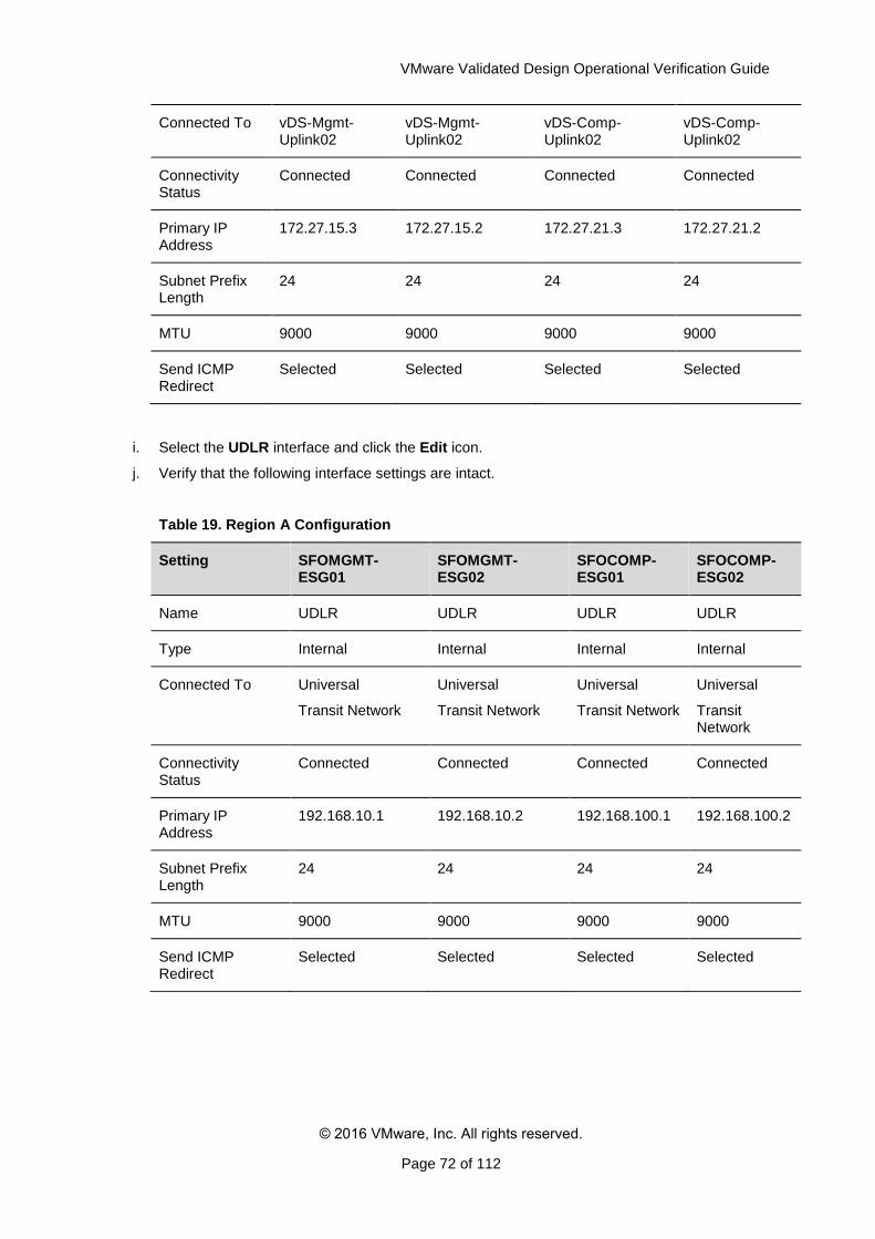
VMware Validated Design Operational Verification Guide
© 2016 VMware, Inc. All rights reserved.
Page 72 of 112
Connected To vDS-Mgmt-Uplink02
vDS-Mgmt-Uplink02
vDS-Comp-Uplink02
vDS-Comp-Uplink02
Connectivity Status
Connected Connected Connected Connected
Primary IP Address
172.27.15.3 172.27.15.2 172.27.21.3 172.27.21.2
Subnet Prefix Length
24 24 24 24
MTU 9000 9000 9000 9000
Send ICMP Redirect
Selected Selected Selected Selected
i. Select the UDLR interface and click the Edit icon.
j. Verify that the following interface settings are intact.
Table 19. Region A Configuration
Setting SFOMGMT-ESG01
SFOMGMT-ESG02
SFOCOMP-ESG01
SFOCOMP-ESG02
Name UDLR UDLR UDLR UDLR
Type Internal Internal Internal Internal
Connected To Universal
Transit Network
Universal
Transit Network
Universal
Transit Network
Universal
Transit Network
Connectivity Status
Connected Connected Connected Connected
Primary IP Address
192.168.10.1 192.168.10.2 192.168.100.1 192.168.100.2
Subnet Prefix Length
24 24 24 24
MTU 9000 9000 9000 9000
Send ICMP Redirect
Selected Selected Selected Selected
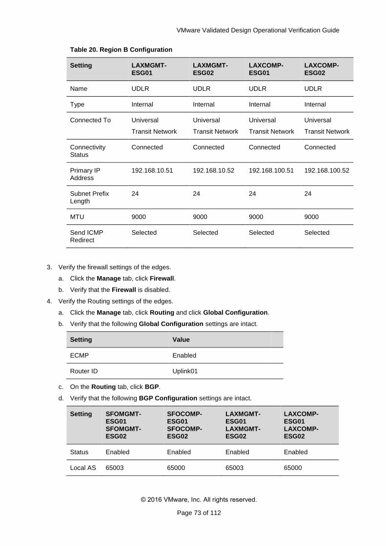
VMware Validated Design Operational Verification Guide
© 2016 VMware, Inc. All rights reserved.
Page 73 of 112
Table 20. Region B Configuration
Setting LAXMGMT-ESG01
LAXMGMT-ESG02
LAXCOMP-ESG01
LAXCOMP-ESG02
Name UDLR UDLR UDLR UDLR
Type Internal Internal Internal Internal
Connected To Universal
Transit Network
Universal
Transit Network
Universal
Transit Network
Universal
Transit Network
Connectivity Status
Connected Connected Connected Connected
Primary IP Address
192.168.10.51 192.168.10.52 192.168.100.51 192.168.100.52
Subnet Prefix Length
24 24 24 24
MTU 9000 9000 9000 9000
Send ICMP Redirect
Selected Selected Selected Selected
3. Verify the firewall settings of the edges.
a. Click the Manage tab, click Firewall.
b. Verify that the Firewall is disabled.
4. Verify the Routing settings of the edges.
a. Click the Manage tab, click Routing and click Global Configuration.
b. Verify that the following Global Configuration settings are intact.
Setting Value
ECMP Enabled
Router ID Uplink01
c. On the Routing tab, click BGP.
d. Verify that the following BGP Configuration settings are intact.
Setting SFOMGMT-ESG01 SFOMGMT-ESG02
SFOCOMP-ESG01 SFOCOMP-ESG02
LAXMGMT-ESG01 LAXMGMT-ESG02
LAXCOMP-ESG01 LAXCOMP-ESG02
Status Enabled Enabled Enabled Enabled
Local AS 65003 65000 65003 65000
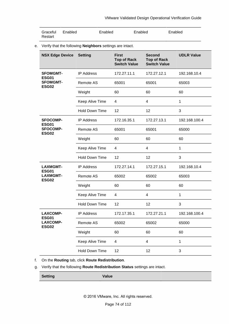
VMware Validated Design Operational Verification Guide
© 2016 VMware, Inc. All rights reserved.
Page 74 of 112
Graceful Restart
Enabled Enabled Enabled Enabled
e. Verify that the following Neighbors settings are intact.
NSX Edge Device Setting First Top of Rack Switch Value
Second Top of Rack Switch Value
UDLR Value
SFOMGMT-ESG01 SFOMGMT-ESG02
IP Address 172.27.11.1 172.27.12.1 192.168.10.4
Remote AS 65001 65001 65003
Weight 60 60 60
Keep Alive Time 4 4 1
Hold Down Time 12 12 3
SFOCOMP-ESG01 SFOCOMP-ESG02
IP Address 172.16.35.1 172.27.13.1 192.168.100.4
Remote AS 65001 65001 65000
Weight 60 60 60
Keep Alive Time 4 4 1
Hold Down Time 12 12 3
LAXMGMT-ESG01 LAXMGMT-ESG02
IP Address 172.27.14.1 172.27.15.1 192.168.10.4
Remote AS 65002 65002 65003
Weight 60 60 60
Keep Alive Time 4 4 1
Hold Down Time 12 12 3
LAXCOMP-ESG01 LAXCOMP-ESG02
IP Address 172.17.35.1 172.27.21.1 192.168.100.4
Remote AS 65002 65002 65000
Weight 60 60 60
Keep Alive Time 4 4 1
Hold Down Time 12 12 3
f. On the Routing tab, click Route Redistribution.
g. Verify that the following Route Redistribution Status settings are intact.
Setting Value
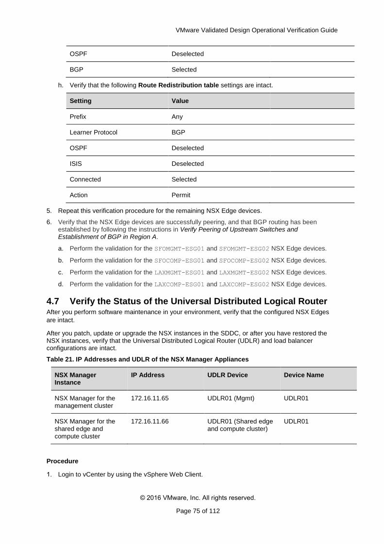
VMware Validated Design Operational Verification Guide
© 2016 VMware, Inc. All rights reserved.
Page 75 of 112
OSPF Deselected
BGP Selected
h. Verify that the following Route Redistribution table settings are intact.
Setting Value
Prefix Any
Learner Protocol BGP
OSPF Deselected
ISIS Deselected
Connected Selected
Action Permit
5. Repeat this verification procedure for the remaining NSX Edge devices.
6. Verify that the NSX Edge devices are successfully peering, and that BGP routing has been established by following the instructions in Verify Peering of Upstream Switches and Establishment of BGP in Region A.
a. Perform the validation for the SFOMGMT-ESG01 and SFOMGMT-ESG02 NSX Edge devices.
b. Perform the validation for the SFOCOMP-ESG01 and SFOCOMP-ESG02 NSX Edge devices.
c. Perform the validation for the LAXMGMT-ESG01 and LAXMGMT-ESG02 NSX Edge devices.
d. Perform the validation for the LAXCOMP-ESG01 and LAXCOMP-ESG02 NSX Edge devices.
4.7 Verify the Status of the Universal Distributed Logical Router After you perform software maintenance in your environment, verify that the configured NSX Edges
are intact.
After you patch, update or upgrade the NSX instances in the SDDC, or after you have restored the NSX instances, verify that the Universal Distributed Logical Router (UDLR) and load balancer configurations are intact.
Table 21. IP Addresses and UDLR of the NSX Manager Appliances
NSX Manager Instance
IP Address UDLR Device Device Name
NSX Manager for the management cluster
172.16.11.65 UDLR01 (Mgmt) UDLR01
NSX Manager for the shared edge and compute cluster
172.16.11.66 UDLR01 (Shared edge and compute cluster)
UDLR01
Procedure
Login to vCenter by using the vSphere Web Client.
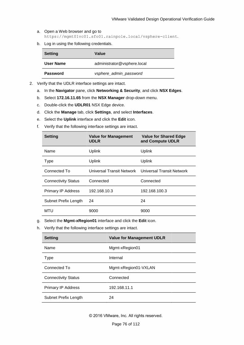
VMware Validated Design Operational Verification Guide
© 2016 VMware, Inc. All rights reserved.
Page 76 of 112
a. Open a Web browser and go to
https://mgmt01vc01.sfo01.rainpole.local/vsphere-client.
b. Log in using the following credentials.
Setting Value
User Name [email protected]
Password vsphere_admin_password
2. Verify that the UDLR interface settings are intact.
a. In the Navigator pane, click Networking & Security, and click NSX Edges.
b. Select 172.16.11.65 from the NSX Manager drop-down menu.
c. Double-click the UDLR01 NSX Edge device.
d. Click the Manage tab, click Settings, and select Interfaces.
e. Select the Uplink interface and click the Edit icon.
f. Verify that the following interface settings are intact.
Setting Value for Management UDLR
Value for Shared Edge and Compute UDLR
Name Uplink Uplink
Type Uplink Uplink
Connected To Universal Transit Network Universal Transit Network
Connectivity Status Connected Connected
Primary IP Address 192.168.10.3 192.168.100.3
Subnet Prefix Length 24 24
MTU 9000 9000
g. Select the Mgmt-xRegion01 interface and click the Edit icon.
h. Verify that the following interface settings are intact.
Setting Value for Management UDLR
Name Mgmt-xRegion01
Type Internal
Connected To Mgmt-xRegion01-VXLAN
Connectivity Status Connected
Primary IP Address 192.168.11.1
Subnet Prefix Length 24
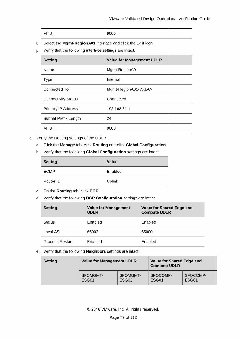
VMware Validated Design Operational Verification Guide
© 2016 VMware, Inc. All rights reserved.
Page 77 of 112
MTU 9000
i. Select the Mgmt-RegionA01 interface and click the Edit icon.
j. Verify that the following interface settings are intact.
Setting Value for Management UDLR
Name Mgmt-RegionA01
Type Internal
Connected To Mgmt-RegionA01-VXLAN
Connectivity Status Connected
Primary IP Address 192.168.31.1
Subnet Prefix Length 24
MTU 9000
3. Verify the Routing settings of the UDLR.
a. Click the Manage tab, click Routing and click Global Configuration.
b. Verify that the following Global Configuration settings are intact.
Setting Value
ECMP Enabled
Router ID Uplink
c. On the Routing tab, click BGP.
d. Verify that the following BGP Configuration settings are intact.
Setting Value for Management UDLR
Value for Shared Edge and Compute UDLR
Status Enabled Enabled
Local AS 65003 65000
Graceful Restart Enabled Enabled
e. Verify that the following Neighbors settings are intact.
Setting Value for Management UDLR Value for Shared Edge and Compute UDLR
SFOMGMT-ESG01
SFOMGMT-ESG02
SFOCOMP-ESG01
SFOCOMP-ESG01
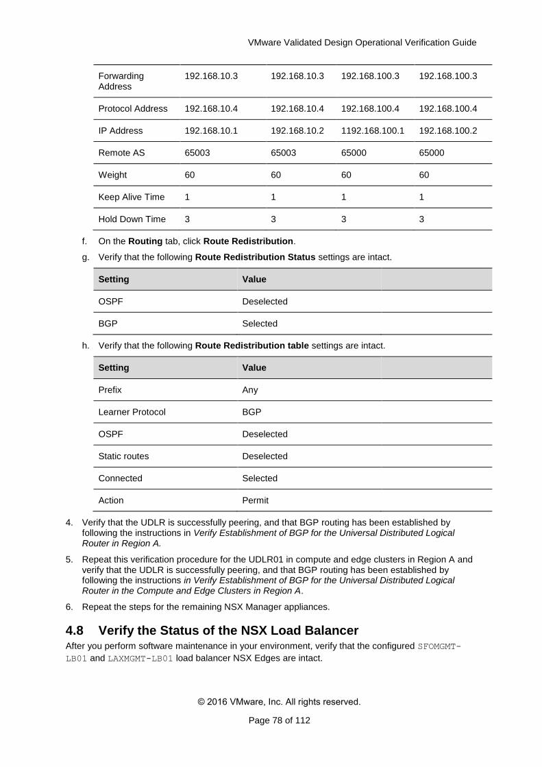
VMware Validated Design Operational Verification Guide
© 2016 VMware, Inc. All rights reserved.
Page 78 of 112
Forwarding Address
192.168.10.3 192.168.10.3 192.168.100.3 192.168.100.3
Protocol Address 192.168.10.4 192.168.10.4 192.168.100.4 192.168.100.4
IP Address 192.168.10.1 192.168.10.2 1192.168.100.1 192.168.100.2
Remote AS 65003 65003 65000 65000
Weight 60 60 60 60
Keep Alive Time 1 1 1 1
Hold Down Time 3 3 3 3
f. On the Routing tab, click Route Redistribution.
g. Verify that the following Route Redistribution Status settings are intact.
Setting Value
OSPF Deselected
BGP Selected
h. Verify that the following Route Redistribution table settings are intact.
Setting Value
Prefix Any
Learner Protocol BGP
OSPF Deselected
Static routes Deselected
Connected Selected
Action Permit
4. Verify that the UDLR is successfully peering, and that BGP routing has been established by following the instructions in Verify Establishment of BGP for the Universal Distributed Logical Router in Region A.
5. Repeat this verification procedure for the UDLR01 in compute and edge clusters in Region A and verify that the UDLR is successfully peering, and that BGP routing has been established by following the instructions in Verify Establishment of BGP for the Universal Distributed Logical Router in the Compute and Edge Clusters in Region A.
6. Repeat the steps for the remaining NSX Manager appliances.
4.8 Verify the Status of the NSX Load Balancer After you perform software maintenance in your environment, verify that the configured SFOMGMT-
LB01 and LAXMGMT-LB01 load balancer NSX Edges are intact.
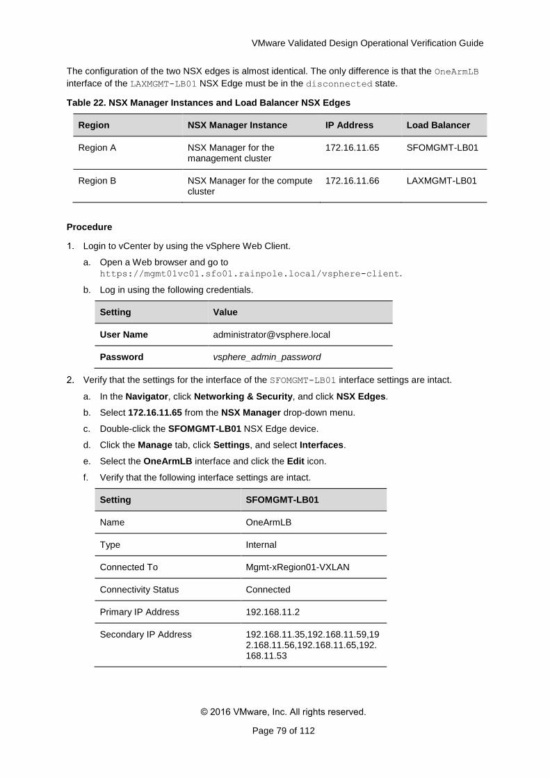
VMware Validated Design Operational Verification Guide
© 2016 VMware, Inc. All rights reserved.
Page 79 of 112
The configuration of the two NSX edges is almost identical. The only difference is that the OneArmLB
interface of the LAXMGMT-LB01 NSX Edge must be in the disconnected state.
Table 22. NSX Manager Instances and Load Balancer NSX Edges
Region NSX Manager Instance IP Address Load Balancer
Region A NSX Manager for the management cluster
172.16.11.65 SFOMGMT-LB01
Region B NSX Manager for the compute cluster
172.16.11.66 LAXMGMT-LB01
Procedure
Login to vCenter by using the vSphere Web Client.
a. Open a Web browser and go to
https://mgmt01vc01.sfo01.rainpole.local/vsphere-client.
b. Log in using the following credentials.
Setting Value
User Name [email protected]
Password vsphere_admin_password
Verify that the settings for the interface of the SFOMGMT-LB01 interface settings are intact.
a. In the Navigator, click Networking & Security, and click NSX Edges.
b. Select 172.16.11.65 from the NSX Manager drop-down menu.
c. Double-click the SFOMGMT-LB01 NSX Edge device.
d. Click the Manage tab, click Settings, and select Interfaces.
e. Select the OneArmLB interface and click the Edit icon.
f. Verify that the following interface settings are intact.
Setting SFOMGMT-LB01
Name OneArmLB
Type Internal
Connected To Mgmt-xRegion01-VXLAN
Connectivity Status Connected
Primary IP Address 192.168.11.2
Secondary IP Address 192.168.11.35,192.168.11.59,192.168.11.56,192.168.11.65,192.168.11.53
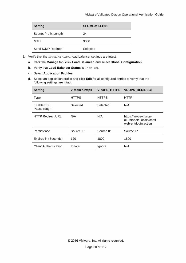
VMware Validated Design Operational Verification Guide
© 2016 VMware, Inc. All rights reserved.
Page 80 of 112
Setting SFOMGMT-LB01
Subnet Prefix Length 24
MTU 9000
Send ICMP Redirect Selected
Verify that the SFOMGMT-LB01 load balancer settings are intact.
a. Click the Manage tab, click Load Balancer, and select Global Configuration.
b. Verify that Load Balancer Status is Enabled.
c. Select Application Profiles.
d. Select an application profile and click Edit for all configured entries to verify that the following settings are intact.
Setting vRealize-https VROPS_HTTPS VROPS_REDIRECT
Type HTTPS HTTPS HTTP
Enable SSL Passthrough
Selected Selected N/A
HTTP Redirect URL N/A N/A https://vrops-cluster-01.rainpole.local/vcops-web-ent/login.action
Persistence Source IP Source IP Source IP
Expires in (Seconds) 120 1800 1800
Client Authentication Ignore Ignore N/A
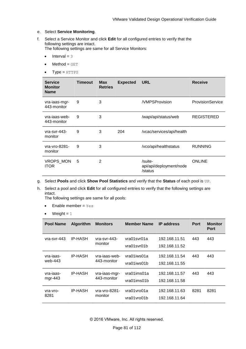
VMware Validated Design Operational Verification Guide
© 2016 VMware, Inc. All rights reserved.
Page 81 of 112
e. Select Service Monitoring.
f. Select a Service Monitor and click Edit for all configured entries to verify that the following settings are intact. The following settings are same for all Service Monitors:
Interval = 3
Method = GET
Type = HTTPS
Service Monitor Name
Timeout Max Retries
Expected URL Receive
vra-iaas-mgr-443-monitor
9 3 /VMPSProvision ProvisionService
vra-iaas-web-443-monitor
9 3 /wapi/api/status/web REGISTERED
vra-svr-443-monitor
9 3 204 /vcac/services/api/health
vra-vro-8281-monitor
9 3 /vco/api/healthstatus RUNNING
VROPS_MONITOR
5 2 /suite-api/api/deployment/node/status
ONLINE
g. Select Pools and click Show Pool Statistics and verify that the Status of each pool is UP.
h. Select a pool and click Edit for all configured entries to verify that the following settings are intact. The following settings are same for all pools:
Enable member = Yes
Weight = 1
Pool Name Algorithm Monitors Member Name IP address Port Monitor Port
vra-svr-443 IP-HASH vra-svr-443-monitor
vra01svr01a
vra01svr01b
192.168.11.51
192.168.11.52
443 443
vra-iaas-web-443
IP-HASH vra-iaas-web-443-monitor
vra01iws01a
vra01iws01b
192.168.11.54
192.168.11.55
443 443
vra-iaas-mgr-443
IP-HASH vra-iaas-mgr-443-monitor
vra01ims01a
vra01ims01b
192.168.11.57
192.168.11.58
443 443
vra-vro-8281
IP-HASH vra-vro-8281-monitor
vra01vro01a
vra01vro01b
192.168.11.63
192.168.11.64
8281
8281
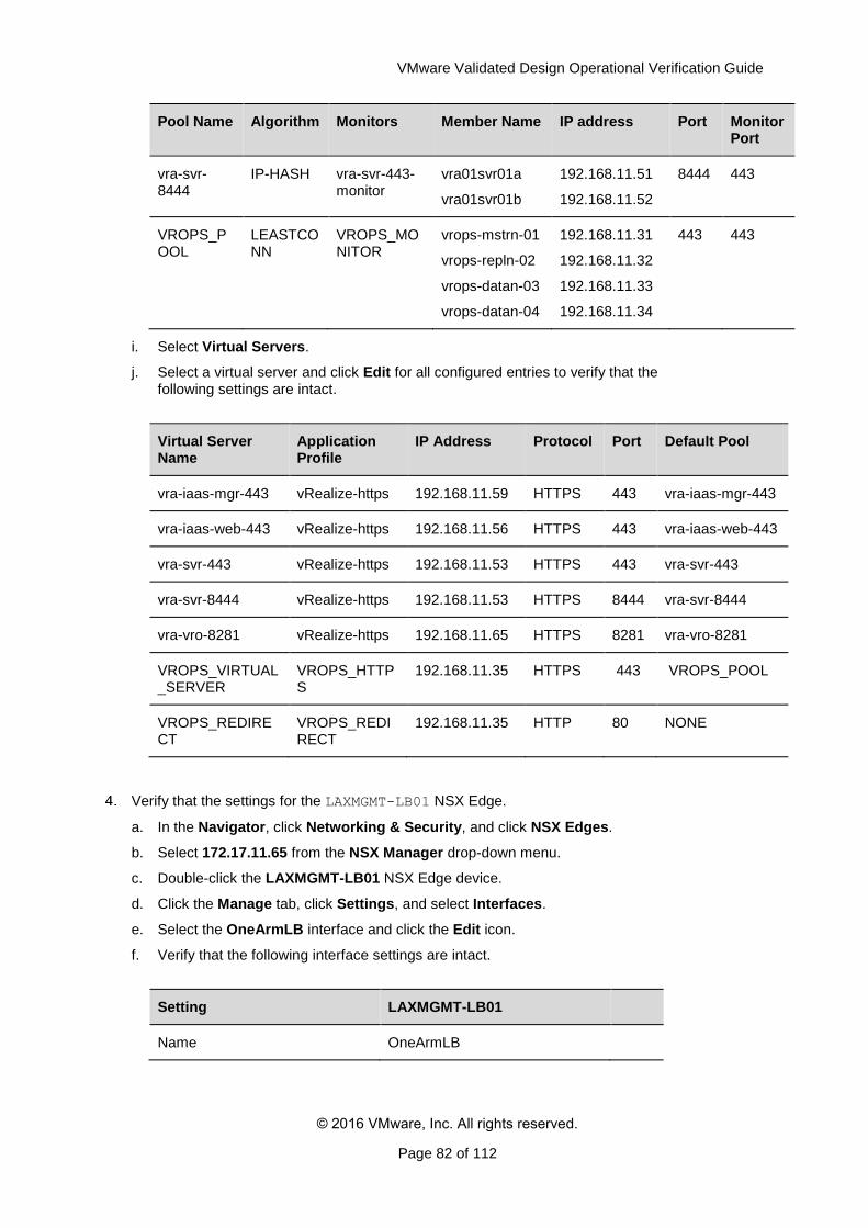
VMware Validated Design Operational Verification Guide
© 2016 VMware, Inc. All rights reserved.
Page 82 of 112
Pool Name Algorithm Monitors Member Name IP address Port Monitor Port
vra-svr-8444
IP-HASH vra-svr-443-monitor
vra01svr01a
vra01svr01b
192.168.11.51
192.168.11.52
8444 443
VROPS_POOL
LEASTCONN
VROPS_MONITOR
vrops-mstrn-01
vrops-repln-02
vrops-datan-03
vrops-datan-04
192.168.11.31
192.168.11.32
192.168.11.33
192.168.11.34
443 443
i. Select Virtual Servers.
j. Select a virtual server and click Edit for all configured entries to verify that the following settings are intact.
Virtual Server Name
Application Profile
IP Address Protocol Port Default Pool
vra-iaas-mgr-443 vRealize-https 192.168.11.59 HTTPS 443 vra-iaas-mgr-443
vra-iaas-web-443 vRealize-https 192.168.11.56 HTTPS 443 vra-iaas-web-443
vra-svr-443 vRealize-https 192.168.11.53 HTTPS 443 vra-svr-443
vra-svr-8444 vRealize-https 192.168.11.53 HTTPS 8444 vra-svr-8444
vra-vro-8281 vRealize-https 192.168.11.65 HTTPS 8281 vra-vro-8281
VROPS_VIRTUAL_SERVER
VROPS_HTTPS
192.168.11.35 HTTPS 443 VROPS_POOL
VROPS_REDIRECT
VROPS_REDIRECT
192.168.11.35 HTTP 80 NONE
Verify that the settings for the LAXMGMT-LB01 NSX Edge.
a. In the Navigator, click Networking & Security, and click NSX Edges.
b. Select 172.17.11.65 from the NSX Manager drop-down menu.
c. Double-click the LAXMGMT-LB01 NSX Edge device.
d. Click the Manage tab, click Settings, and select Interfaces.
e. Select the OneArmLB interface and click the Edit icon.
f. Verify that the following interface settings are intact.
Setting LAXMGMT-LB01
Name OneArmLB
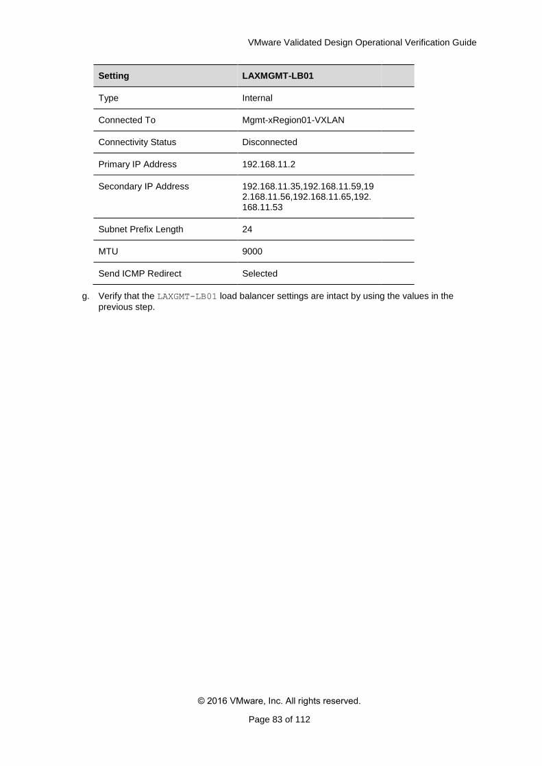
VMware Validated Design Operational Verification Guide
© 2016 VMware, Inc. All rights reserved.
Page 83 of 112
Setting LAXMGMT-LB01
Type Internal
Connected To Mgmt-xRegion01-VXLAN
Connectivity Status Disconnected
Primary IP Address 192.168.11.2
Secondary IP Address 192.168.11.35,192.168.11.59,192.168.11.56,192.168.11.65,192.168.11.53
Subnet Prefix Length 24
MTU 9000
Send ICMP Redirect Selected
g. Verify that the LAXGMT-LB01 load balancer settings are intact by using the values in the
previous step.
VMware Validated Design Operational Verification Guide
© 2016 VMware, Inc. All rights reserved.
Page 84 of 112
5. Validate vRealize Operations Manager
After a maintenance like an update, upgrade, restore or recovery, verify that all vRealize Operations Manager nodes are available.
Verify the functionality of vRealize Operations Manager after a planned maintenance.
Verify the Power Status of All vRealize Operations Manager VMs
Verify the Configuration of vRealize Operations Manager Cluster Nodes and Remote Collectors
Verify the vRealize Operations Manager Load Balancing
Validate vRealize Operations Manager Adapters and Management Packs
5.1 Verify the Power Status of All vRealize Operations Manager VMs
All virtual machines of vRealize Operations Manager must be properly configured and running.
For more information about the FQDNs and IP address of each VM, see the list of registered DNS Names from the Planning and Preparation Guide for this validated design.
Prerequisites
Verify that all vRealize Operations Manager VMs are started in the order described in the SDDC Startup and Shutdown section of this guide.
Procedure
Log in to vCenter Server by using the vSphere Web Client.
a. Open a Web browser and go to the following URL.
Region URL
Region A
https://mgmt01vc01.sfo01.rainpole.local/vsphere-
client
Region B
https://mgmt01vc51.lax01.rainpole.local/vsphere-
client
b. Log in using the following credentials.
Setting Value
User Name [email protected]
Password vsphere_admin_password
2. Verify that all virtual machines of vRealize Operations Manager are powered on and configured properly.
a. On the Home page, click VMs and Templates.
b. In the Navigator, go to the following folder names of vCenter server and verify that the virtual machines are configured in the following way.
VMware Validated Design Operational Verification Guide
© 2016 VMware, Inc. All rights reserved.
Page 85 of 112
Region Folder Name
VM name FQDN IP Address
Region A
vROps01
vrops-mstrn-01 vrops-mstrn-01.rainpole.local
192.168.11.31
vrops-repln-02 vrops-repln-02.rainpole.local
192.168.11.32
vrops-datan-03 vrops-datan-03.rainpole.local
192.168.11.33
vrops-datan-04 vrops-datan-04.rainpole.local
192.168.11.34
vROps01RC
vrops-rmtcol-01 vrops-rmtcol-01.sfo01.rainpole.local
192.168.31.31
vrops-rmtcol-02 vrops-rmtcol-02.sfo01.rainpole.local
192.168.31.32
Region B vROps51RC
vrops-rmtcol-51 vrops-rmtcol-51.lax01.rainpole.local
192.168.32.31
vrops-rmtcol-52 vrops-rmtcol-52.lax01.rainpole.local
192.168.32.32
5.2 Verify the Configuration of vRealize Operations Manager Cluster Nodes and Remote Collectors
After performing planned maintenance in your environment, verify that vRealize Operations Manager Cluster nodes and Remote Collectors are online and performing the data collection.
Verify the following configurations:
vRealize Operations Manager health
Self Monitoring dashboard
Authentication sources
Certificates
Licensing
Procedure
Log in to vRealize Operations Manager.
a. Open a Web browser and go to https://vrops-cluster-01.rainpole.local.
b. Log in using the following credentials.
Setting Value
User Name admin
Password vrops_admin_password
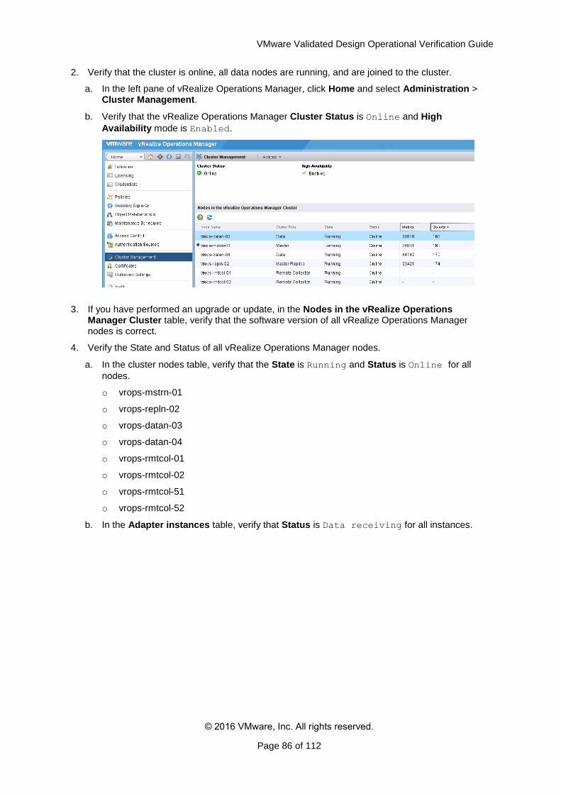
VMware Validated Design Operational Verification Guide
© 2016 VMware, Inc. All rights reserved.
Page 86 of 112
2. Verify that the cluster is online, all data nodes are running, and are joined to the cluster.
a. In the left pane of vRealize Operations Manager, click Home and select Administration > Cluster Management.
b. Verify that the vRealize Operations Manager Cluster Status is Online and High
Availability mode is Enabled.
3. If you have performed an upgrade or update, in the Nodes in the vRealize Operations Manager Cluster table, verify that the software version of all vRealize Operations Manager nodes is correct.
4. Verify the State and Status of all vRealize Operations Manager nodes.
a. In the cluster nodes table, verify that the State is Running and Status is Online for all
nodes.
o vrops-mstrn-01
o vrops-repln-02
o vrops-datan-03
o vrops-datan-04
o vrops-rmtcol-01
o vrops-rmtcol-02
o vrops-rmtcol-51
o vrops-rmtcol-52
b. In the Adapter instances table, verify that Status is Data receiving for all instances.
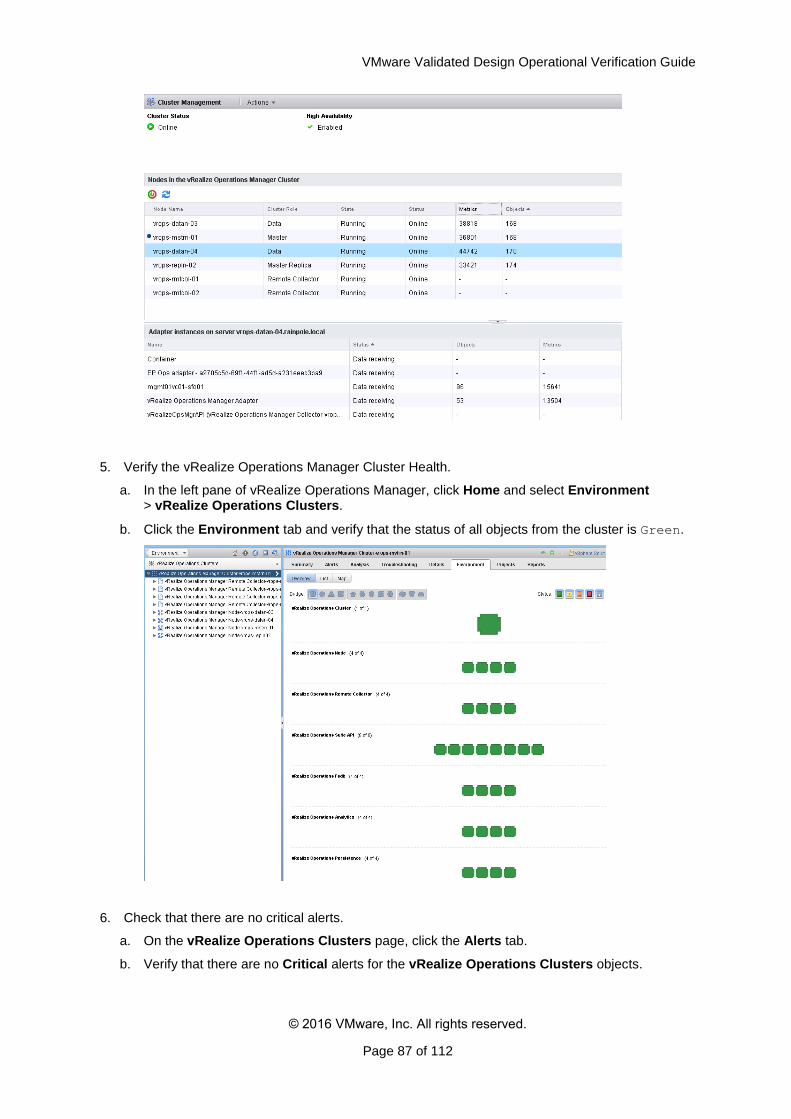
VMware Validated Design Operational Verification Guide
© 2016 VMware, Inc. All rights reserved.
Page 87 of 112
5. Verify the vRealize Operations Manager Cluster Health.
a. In the left pane of vRealize Operations Manager, click Home and select Environment > vRealize Operations Clusters.
b. Click the Environment tab and verify that the status of all objects from the cluster is Green.
6. Check that there are no critical alerts.
a. On the vRealize Operations Clusters page, click the Alerts tab.
b. Verify that there are no Critical alerts for the vRealize Operations Clusters objects.
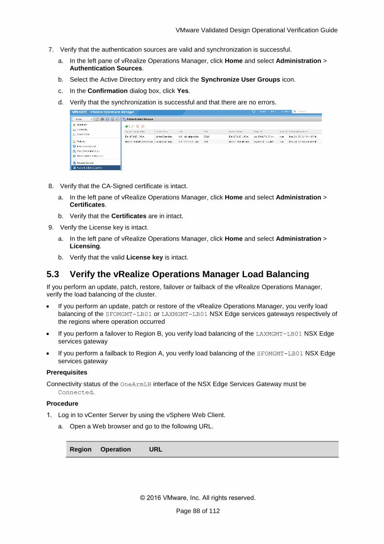
VMware Validated Design Operational Verification Guide
© 2016 VMware, Inc. All rights reserved.
Page 88 of 112
7. Verify that the authentication sources are valid and synchronization is successful.
a. In the left pane of vRealize Operations Manager, click Home and select Administration > Authentication Sources.
b. Select the Active Directory entry and click the Synchronize User Groups icon.
c. In the Confirmation dialog box, click Yes.
d. Verify that the synchronization is successful and that there are no errors.
8. Verify that the CA-Signed certificate is intact.
a. In the left pane of vRealize Operations Manager, click Home and select Administration > Certificates.
b. Verify that the Certificates are in intact.
9. Verify the License key is intact.
a. In the left pane of vRealize Operations Manager, click Home and select Administration > Licensing.
b. Verify that the valid License key is intact.
5.3 Verify the vRealize Operations Manager Load Balancing
If you perform an update, patch, restore, failover or failback of the vRealize Operations Manager, verify the load balancing of the cluster.
If you perform an update, patch or restore of the vRealize Operations Manager, you verify load
balancing of the SFOMGMT-LB01 or LAXMGMT-LB01 NSX Edge services gateways respectively of
the regions where operation occurred
If you perform a failover to Region B, you verify load balancing of the LAXMGMT-LB01 NSX Edge
services gateway
If you perform a failback to Region A, you verify load balancing of the SFOMGMT-LB01 NSX Edge
services gateway
Prerequisites
Connectivity status of the OneArmLB interface of the NSX Edge Services Gateway must be
Connected.
Procedure
Log in to vCenter Server by using the vSphere Web Client.
a. Open a Web browser and go to the following URL.
Region Operation URL
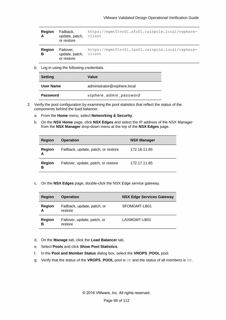
VMware Validated Design Operational Verification Guide
© 2016 VMware, Inc. All rights reserved.
Page 89 of 112
Region A
Failback, update, patch, or restore
https://mgmt01vc01.sfo01.rainpole.local/vsphere-
client
Region B
Failover, update, patch, or restore
https://mgmt01vc51.lax01.rainpole.local/vsphere-
client
b. Log in using the following credentials.
Setting Value
User Name [email protected]
Password vsphere_admin_password
Verify the pool configuration by examining the pool statistics that reflect the status of the components behind the load balancer.
a. From the Home menu, select Networking & Security.
b. On the NSX Home page, click NSX Edges and select the IP address of the NSX Manager from the NSX Manager drop-down menu at the top of the NSX Edges page.
Region Operation NSX Manager
Region A
Failback, update, patch, or restore 172.16.11.65
Region B
Failover, update, patch, or restore 172.17.11.65
c. On the NSX Edges page, double-click the NSX Edge service gateway.
Region Operation NSX Edge Services Gateway
Region A
Failback, update, patch, or restore
SFOMGMT-LB01
Region B
Failover, update, patch, or restore
LAXMGMT-LB01
d. On the Manage tab, click the Load Balancer tab.
e. Select Pools and click Show Pool Statistics.
f. In the Pool and Member Status dialog box, select the VROPS_POOL pool.
g. Verify that the status of the VROPS_POOL pool is UP and the status of all members is UP.
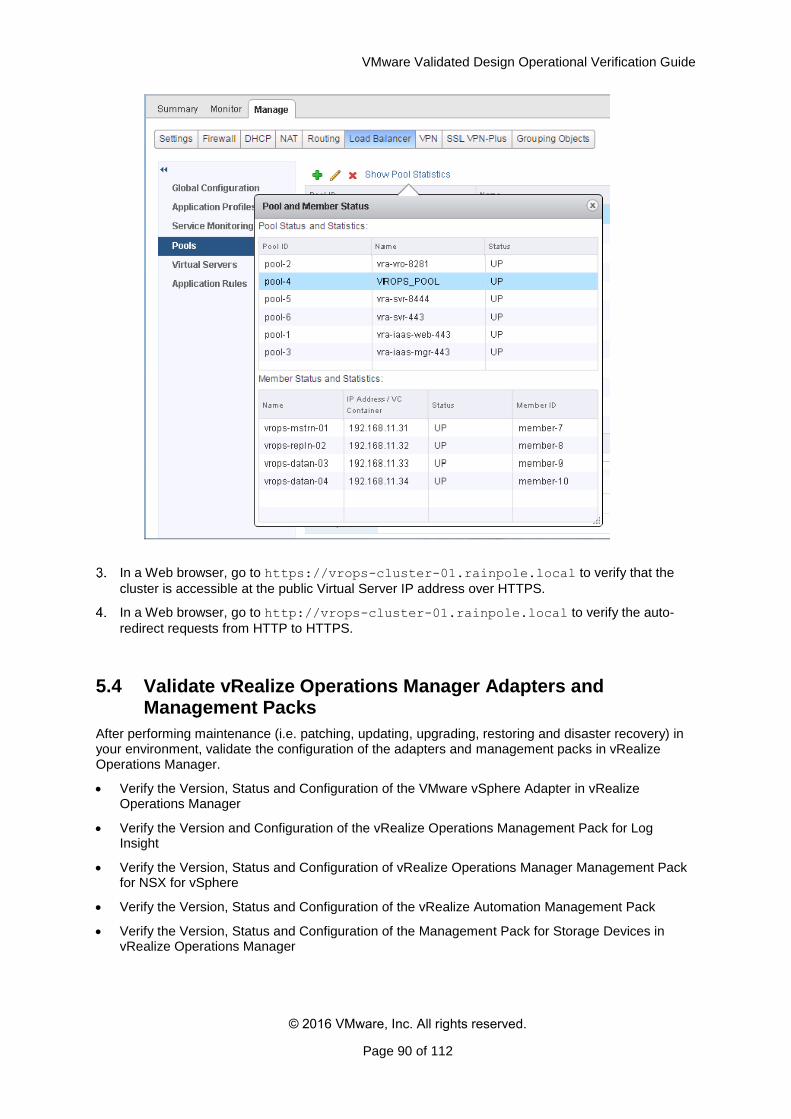
VMware Validated Design Operational Verification Guide
© 2016 VMware, Inc. All rights reserved.
Page 90 of 112
In a Web browser, go to https://vrops-cluster-01.rainpole.local to verify that the
cluster is accessible at the public Virtual Server IP address over HTTPS.
In a Web browser, go to http://vrops-cluster-01.rainpole.local to verify the auto-
redirect requests from HTTP to HTTPS.
5.4 Validate vRealize Operations Manager Adapters and Management Packs
After performing maintenance (i.e. patching, updating, upgrading, restoring and disaster recovery) in your environment, validate the configuration of the adapters and management packs in vRealize Operations Manager.
Verify the Version, Status and Configuration of the VMware vSphere Adapter in vRealize Operations Manager
Verify the Version and Configuration of the vRealize Operations Management Pack for Log Insight
Verify the Version, Status and Configuration of vRealize Operations Manager Management Pack for NSX for vSphere
Verify the Version, Status and Configuration of the vRealize Automation Management Pack
Verify the Version, Status and Configuration of the Management Pack for Storage Devices in vRealize Operations Manager
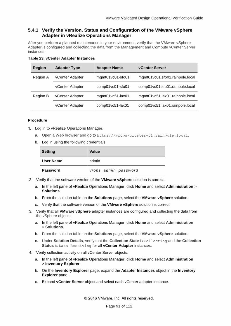
VMware Validated Design Operational Verification Guide
© 2016 VMware, Inc. All rights reserved.
Page 91 of 112
5.4.1 Verify the Version, Status and Configuration of the VMware vSphere Adapter in vRealize Operations Manager
After you perform a planned maintenance in your environment, verify that the VMware vSphere Adapter is configured and collecting the data from the Management and Compute vCenter Server instances.
Table 23. vCenter Adapter Instances
Region Adapter Type Adapter Name vCenter Server
Region A vCenter Adapter mgmt01vc01-sfo01 mgmt01vc01.sfo01.rainpole.local
vCenter Adapter comp01vc01-sfo01 comp01vc01.sfo01.rainpole.local
Region B vCenter Adapter mgmt01vc51-lax01 mgmt01vc51.lax01.rainpole.local
vCenter Adapter comp01vc51-lax01 comp01vc51.lax01.rainpole.local
Procedure
Log in to vRealize Operations Manager.
a. Open a Web browser and go to https://vrops-cluster-01.rainpole.local.
b. Log in using the following credentials.
Setting Value
User Name admin
Password vrops_admin_password
2. Verify that the software version of the VMware vSphere solution is correct.
a. In the left pane of vRealize Operations Manager, click Home and select Administration > Solutions.
b. From the solution table on the Solutions page, select the VMware vSphere solution.
c. Verify that the software version of the VMware vSphere solution is correct.
3. Verify that all VMware vSphere adapter instances are configured and collecting the data from the vSphere objects.
a. In the left pane of vRealize Operations Manager, click Home and select Administration > Solutions.
b. From the solution table on the Solutions page, select the VMware vSphere solution.
c. Under Solution Details, verify that the Collection State is Collecting and the Collection
Status is Data Receiving for all vCenter Adapter instances.
4. Verify collection activity on all vCenter Server objects.
a. In the left pane of vRealize Operations Manager, click Home and select Administration > Inventory Explorer.
b. On the Inventory Explorer page, expand the Adapter Instances object in the Inventory Explorer pane.
c. Expand vCenter Server object and select each vCenter adapter instance.
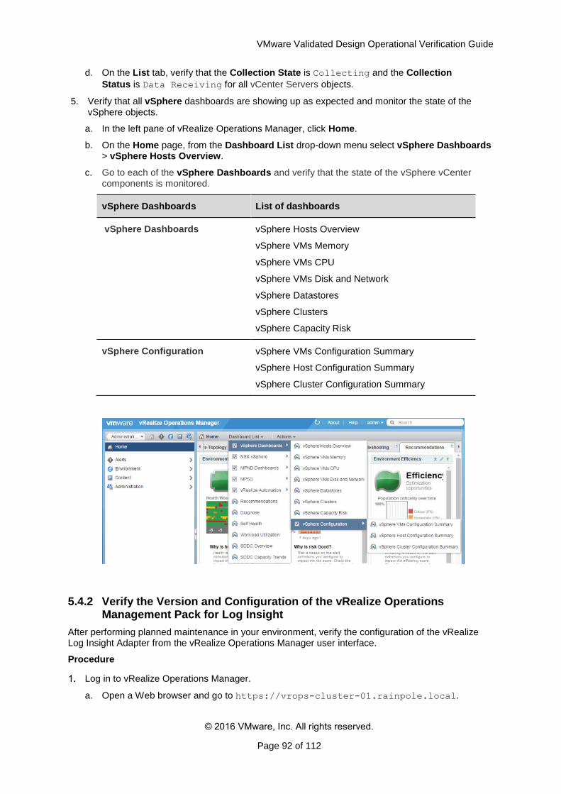
VMware Validated Design Operational Verification Guide
© 2016 VMware, Inc. All rights reserved.
Page 92 of 112
d. On the List tab, verify that the Collection State is Collecting and the Collection
Status is Data Receiving for all vCenter Servers objects.
5. Verify that all vSphere dashboards are showing up as expected and monitor the state of the vSphere objects.
a. In the left pane of vRealize Operations Manager, click Home.
b. On the Home page, from the Dashboard List drop-down menu select vSphere Dashboards > vSphere Hosts Overview.
c. Go to each of the vSphere Dashboards and verify that the state of the vSphere vCenter components is monitored.
vSphere Dashboards List of dashboards
vSphere Dashboards vSphere Hosts Overview
vSphere VMs Memory
vSphere VMs CPU
vSphere VMs Disk and Network
vSphere Datastores
vSphere Clusters
vSphere Capacity Risk
vSphere Configuration vSphere VMs Configuration Summary
vSphere Host Configuration Summary
vSphere Cluster Configuration Summary
5.4.2 Verify the Version and Configuration of the vRealize Operations Management Pack for Log Insight
After performing planned maintenance in your environment, verify the configuration of the vRealize Log Insight Adapter from the vRealize Operations Manager user interface.
Procedure
Log in to vRealize Operations Manager.
a. Open a Web browser and go to https://vrops-cluster-01.rainpole.local.
VMware Validated Design Operational Verification Guide
© 2016 VMware, Inc. All rights reserved.
Page 93 of 112
b. Log in using the following credentials.
Setting Value
User Name admin
Password vrops_admin_password
2. Verify that the software version of the vRealize Operations Management Pack for Log Insight is correct.
a. In the left pane of vRealize Operations Manager, click Home and select Administration > Solutions.
b. From the solution table on the Solutions page, select the VMware vRealize Operations Management Pack for Log Insight solution.
c. Verify that the software version of the solution is correct.
3. Verify that the vRealize Log Insight Adapter instance exists.
a. In the left pane of vRealize Operations Manager, click Home and select Administration > Solutions.
b. From the solution table on the Solutions page, select the VMware vRealize Operations Management Pack for Log Insight solution.
c. Under Solution Details, verify that the vRealize Log Insight Adapter instance exists.
5.4.3 Verify the Version, Status and Configuration of vRealize Operations Manager Management Pack for NSX for vSphere
After you perform a planned maintenance in your environment, verify the configuration of the NSX for vSphere Adapters from the vRealize Operations Manager user interface. Verify also that vRealize Operations Manager receives monitoring data from the NSX Manager instances and from the physical network.
Verify the following configurations:
NSX-vSphere Adapter is configured and collecting the data from the management and compute NSX Managers
Network Devices Adapter is configured and monitoring the switches and routers
Table 24. NSX-vSphere Adapter Instances
Region Adapter Type Adapter Name NSX Manager Host
Region A NSX-vSphere Adapter
Mgmt NSX Adapter - SFO01
mgmt01nsxm01.sfo01.rainpole.local
NSX-vSphere Adapter
Comp NSX Adapter - SFO01
comp01nsxm01.sfo01.rainpole.local
Region B NSX-vSphere Adapter
Mgmt NSX Adapter - LAX01
mgmt01nsxm51.lax01.rainpole.local
NSX-vSphere Adapter
Comp NSX Adapter - LAX01
comp01nsxm51.lax01.rainpole.local
VMware Validated Design Operational Verification Guide
© 2016 VMware, Inc. All rights reserved.
Page 94 of 112
Table 25. Network Devices Adapter Instance
Adapter Type Adapter Name
Network Devices Adapter Network Devices Adapter
Procedure
Log in to vRealize Operations Manager.
a. Open a Web browser and go to https://vrops-cluster-01.rainpole.local.
b. Log in using the following credentials.
Setting Value
User Name admin
Password vrops_admin_password
2. Verify that the software version of the Management Pack for NSX-vSphere is correct.
a. In the left pane of vRealize Operations Manager, click Home and select Administration > Solutions.
b. From the solution table on the Solutions page, select the Management Pack for NSX-vSphere solution.
c. Verify that the software version of Management Pack for NSX-vSphere solution is correct.
3. Verify that all NSX-vSphere Adapter instances are configured and collecting the data from the management and compute NSX Managers.
a. In the left pane of vRealize Operations Manager, click Home and select Administration > Solutions.
b. On the Solutions page, from the solution table, select the Management Pack for NSX-vSphere solution.
c. Under Solution Details, verify that the Collection State is Collecting and the Collection
Status is Data Receiving for all NSX-vSphere Adapter instances.
4. Verify that all Network Devices Adapter instances are configured and collecting the data about the network devices.
a. In the left pane of vRealize Operations Manager, click Home and select Administration > Solutions.
b. From the solution table on the Solutions page, select the Management Pack for NSX-vSphere solution.
c. Under Solution Details, verify that the Collection State is Collecting and
the Collection Status is Data Receiving for the Network Devices Adapter instance.
5. Verify the collection activity of the NSX-vSphere Environment objects.
a. In the left pane of vRealize Operations Manager, click Home and select Administration > Inventory Explorer.
b. On the Inventory Explorer page, expand the Adapter Instances object in the Inventory Explorer pane.
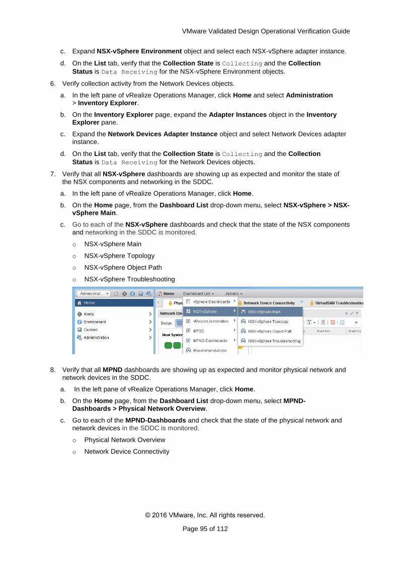
VMware Validated Design Operational Verification Guide
© 2016 VMware, Inc. All rights reserved.
Page 95 of 112
c. Expand NSX-vSphere Environment object and select each NSX-vSphere adapter instance.
d. On the List tab, verify that the Collection State is Collecting and the Collection
Status is Data Receiving for the NSX-vSphere Environment objects.
6. Verify collection activity from the Network Devices objects.
a. In the left pane of vRealize Operations Manager, click Home and select Administration > Inventory Explorer.
b. On the Inventory Explorer page, expand the Adapter Instances object in the Inventory Explorer pane.
c. Expand the Network Devices Adapter Instance object and select Network Devices adapter instance.
d. On the List tab, verify that the Collection State is Collecting and the Collection
Status is Data Receiving for the Network Devices objects.
7. Verify that all NSX-vSphere dashboards are showing up as expected and monitor the state of the NSX components and networking in the SDDC.
a. In the left pane of vRealize Operations Manager, click Home.
b. On the Home page, from the Dashboard List drop-down menu, select NSX-vSphere > NSX-vSphere Main.
c. Go to each of the NSX-vSphere dashboards and check that the state of the NSX components and networking in the SDDC is monitored.
o NSX-vSphere Main
o NSX-vSphere Topology
o NSX-vSphere Object Path
o NSX-vSphere Troubleshooting
8. Verify that all MPND dashboards are showing up as expected and monitor physical network and network devices in the SDDC.
a. In the left pane of vRealize Operations Manager, click Home.
b. On the Home page, from the Dashboard List drop-down menu, select MPND-Dashboards > Physical Network Overview.
c. Go to each of the MPND-Dashboards and check that the state of the physical network and network devices in the SDDC is monitored.
o Physical Network Overview
o Network Device Connectivity
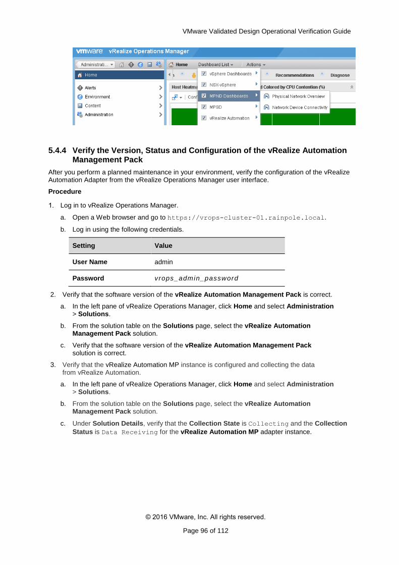
VMware Validated Design Operational Verification Guide
© 2016 VMware, Inc. All rights reserved.
Page 96 of 112
5.4.4 Verify the Version, Status and Configuration of the vRealize Automation Management Pack
After you perform a planned maintenance in your environment, verify the configuration of the vRealize Automation Adapter from the vRealize Operations Manager user interface.
Procedure
Log in to vRealize Operations Manager.
a. Open a Web browser and go to https://vrops-cluster-01.rainpole.local.
b. Log in using the following credentials.
Setting Value
User Name admin
Password vrops_admin_password
2. Verify that the software version of the vRealize Automation Management Pack is correct.
a. In the left pane of vRealize Operations Manager, click Home and select Administration > Solutions.
b. From the solution table on the Solutions page, select the vRealize Automation Management Pack solution.
c. Verify that the software version of the vRealize Automation Management Pack solution is correct.
3. Verify that the vRealize Automation MP instance is configured and collecting the data from vRealize Automation.
a. In the left pane of vRealize Operations Manager, click Home and select Administration > Solutions.
b. From the solution table on the Solutions page, select the vRealize Automation Management Pack solution.
c. Under Solution Details, verify that the Collection State is Collecting and the Collection
Status is Data Receiving for the vRealize Automation MP adapter instance.
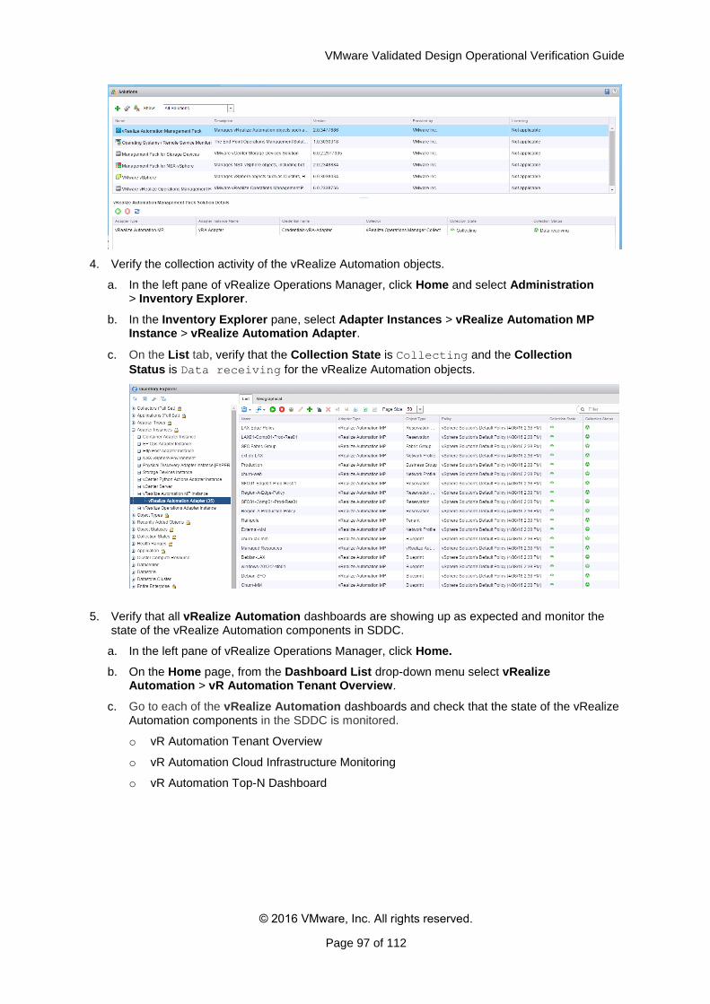
VMware Validated Design Operational Verification Guide
© 2016 VMware, Inc. All rights reserved.
Page 97 of 112
4. Verify the collection activity of the vRealize Automation objects.
a. In the left pane of vRealize Operations Manager, click Home and select Administration > Inventory Explorer.
b. In the Inventory Explorer pane, select Adapter Instances > vRealize Automation MP Instance > vRealize Automation Adapter.
c. On the List tab, verify that the Collection State is Collecting and the Collection
Status is Data receiving for the vRealize Automation objects.
5. Verify that all vRealize Automation dashboards are showing up as expected and monitor the state of the vRealize Automation components in SDDC.
a. In the left pane of vRealize Operations Manager, click Home.
b. On the Home page, from the Dashboard List drop-down menu select vRealize Automation > vR Automation Tenant Overview.
c. Go to each of the vRealize Automation dashboards and check that the state of the vRealize Automation components in the SDDC is monitored.
o vR Automation Tenant Overview
o vR Automation Cloud Infrastructure Monitoring
o vR Automation Top-N Dashboard
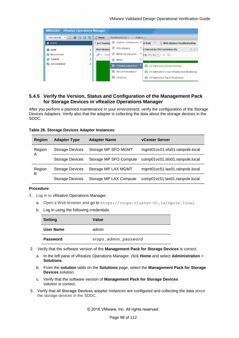
VMware Validated Design Operational Verification Guide
© 2016 VMware, Inc. All rights reserved.
Page 98 of 112
5.4.5 Verify the Version, Status and Configuration of the Management Pack for Storage Devices in vRealize Operations Manager
After you perform a planned maintenance in your environment, verify the configuration of the Storage Devices Adapters. Verify also that the adapter is collecting the data about the storage devices in the SDDC.
Table 26. Storage Devices Adapter Instances
Region Adapter Type Adapter Name vCenter Server
Region A
Storage Devices Storage MP SFO MGMT mgmt01vc01.sfo01.rainpole.local
Storage Devices Storage MP SFO Compute comp01vc01.sfo01.rainpole.local
Region B
Storage Devices Storage MP LAX MGMT mgmt01vc51.lax01.rainpole.local
Storage Devices Storage MP LAX Compute comp01vc51.lax01.rainpole.local
Procedure
Log in to vRealize Operations Manager.
a. Open a Web browser and go to https://vrops-cluster-01.rainpole.local.
b. Log in using the following credentials.
Setting Value
User Name admin
Password vrops_admin_password
2. Verify that the software version of the Management Pack for Storage Devices is correct.
a. In the left pane of vRealize Operations Manager, click Home and select Administration > Solutions.
b. From the solution table on the Solutions page, select the Management Pack for Storage Devices solution.
c. Verify that the software version of Management Pack for Storage Devices solution is correct.
3. Verify that all Storage Devices adapter instances are configured and collecting the data about the storage devices in the SDDC.
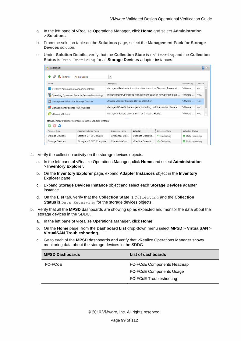
VMware Validated Design Operational Verification Guide
© 2016 VMware, Inc. All rights reserved.
Page 99 of 112
a. In the left pane of vRealize Operations Manager, click Home and select Administration > Solutions.
b. From the solution table on the Solutions page, select the Management Pack for Storage Devices solution.
c. Under Solution Details, verify that the Collection State is Collecting and the Collection
Status is Data Receiving for all Storage Devices adapter instances.
4. Verify the collection activity on the storage devices objects.
a. In the left pane of vRealize Operations Manager, click Home and select Administration > Inventory Explorer.
b. On the Inventory Explorer page, expand Adapter Instances object in the Inventory Explorer pane.
c. Expand Storage Devices Instance object and select each Storage Devices adapter instance.
d. On the List tab, verify that the Collection State is Collecting and the Collection
Status is Data Receiving for the storage devices objects.
5. Verify that all the MPSD dashboards are showing up as expected and monitor the data about the storage devices in the SDDC.
a. In the left pane of vRealize Operations Manager, click Home.
b. On the Home page, from the Dashboard List drop-down menu select MPSD > VirtualSAN > VirtualSAN Troubleshooting.
c. Go to each of the MPSD dashboards and verify that vRealize Operations Manager shows monitoring data about the storage devices in the SDDC.
MPSD Dashboards List of dashboards
FC-FCoE FC-FCoE Components Heatmap
FC-FCoE Components Usage
FC-FCoE Troubleshooting
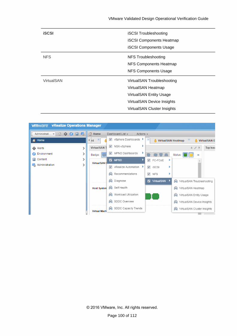
VMware Validated Design Operational Verification Guide
© 2016 VMware, Inc. All rights reserved.
Page 100 of 112
iSCSI iSCSI Troubleshooting
iSCSI Components Heatmap
iSCSI Components Usage
NFS NFS Troubleshooting
NFS Components Heatmap
NFS Components Usage
VirtualSAN VirtualSAN Troubleshooting
VirtualSAN Heatmap
VirtualSAN Entity Usage
VirtualSAN Device Insights
VirtualSAN Cluster Insights
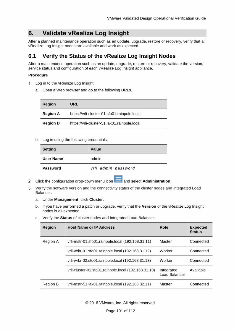
VMware Validated Design Operational Verification Guide
© 2016 VMware, Inc. All rights reserved.
Page 101 of 112
6. Validate vRealize Log Insight
After a planned maintenance operation such as an update, upgrade, restore or recovery, verify that all vRealize Log Insight nodes are available and work as expected.
6.1 Verify the Status of the vRealize Log Insight Nodes
After a maintenance operation such as an update, upgrade, restore or recovery, validate the version, service status and configuration of each vRealize Log Insight appliance.
Procedure
Log in to the vRealize Log Insight.
a. Open a Web browser and go to the following URLs.
Region URL
Region A https://vrli-cluster-01.sfo01.rainpole.local
Region B https://vrli-cluster-51.lax01.rainpole.local
b. Log in using the following credentials.
Setting Value
User Name admin
Password vr l i_admin_password
Click the configuration drop-down menu icon and select Administration.
Verify the software version and the connectivity status of the cluster nodes and Integrated Load Balancer.
a. Under Management, click Cluster.
b. If you have performed a patch or upgrade, verify that the Version of the vRealize Log Insight nodes is as expected.
c. Verify the Status of cluster nodes and Integrated Load Balancer.
Region Host Name or IP Address Role Expected Status
Region A
vrli-mstr-01.sfo01.rainpole.local (192.168.31.11) Master Connected
vrli-wrkr-01.sfo01.rainpole.local (192.168.31.12) Worker Connected
vrli-wrkr-02.sfo01.rainpole.local (192.168.31.13) Worker Connected
vrli-cluster-01.sfo01.rainpole.local (192.168.31.10) Integrated Load Balancer
Available
Region B vrli-mstr-51.lax01.rainpole.local (192.168.32.11) Master Connected
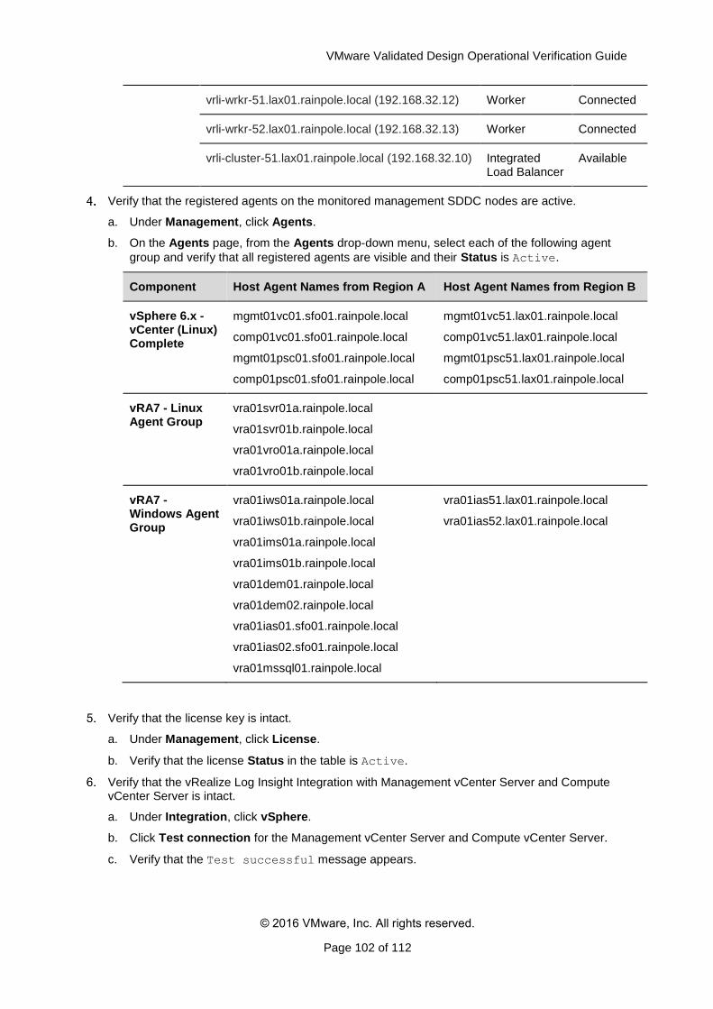
VMware Validated Design Operational Verification Guide
© 2016 VMware, Inc. All rights reserved.
Page 102 of 112
vrli-wrkr-51.lax01.rainpole.local (192.168.32.12) Worker Connected
vrli-wrkr-52.lax01.rainpole.local (192.168.32.13) Worker Connected
vrli-cluster-51.lax01.rainpole.local (192.168.32.10) Integrated Load Balancer
Available
Verify that the registered agents on the monitored management SDDC nodes are active.
a. Under Management, click Agents.
b. On the Agents page, from the Agents drop-down menu, select each of the following agent
group and verify that all registered agents are visible and their Status is Active.
Component Host Agent Names from Region A Host Agent Names from Region B
vSphere 6.x - vCenter (Linux) Complete
mgmt01vc01.sfo01.rainpole.local
comp01vc01.sfo01.rainpole.local
mgmt01psc01.sfo01.rainpole.local
comp01psc01.sfo01.rainpole.local
mgmt01vc51.lax01.rainpole.local
comp01vc51.lax01.rainpole.local
mgmt01psc51.lax01.rainpole.local
comp01psc51.lax01.rainpole.local
vRA7 - Linux Agent Group
vra01svr01a.rainpole.local
vra01svr01b.rainpole.local
vra01vro01a.rainpole.local
vra01vro01b.rainpole.local
vRA7 - Windows Agent Group
vra01iws01a.rainpole.local
vra01iws01b.rainpole.local
vra01ims01a.rainpole.local
vra01ims01b.rainpole.local
vra01dem01.rainpole.local
vra01dem02.rainpole.local
vra01ias01.sfo01.rainpole.local
vra01ias02.sfo01.rainpole.local
vra01mssql01.rainpole.local
vra01ias51.lax01.rainpole.local
vra01ias52.lax01.rainpole.local
Verify that the license key is intact.
a. Under Management, click License.
b. Verify that the license Status in the table is Active.
Verify that the vRealize Log Insight Integration with Management vCenter Server and Compute vCenter Server is intact.
a. Under Integration, click vSphere.
b. Click Test connection for the Management vCenter Server and Compute vCenter Server.
c. Verify that the Test successful message appears.
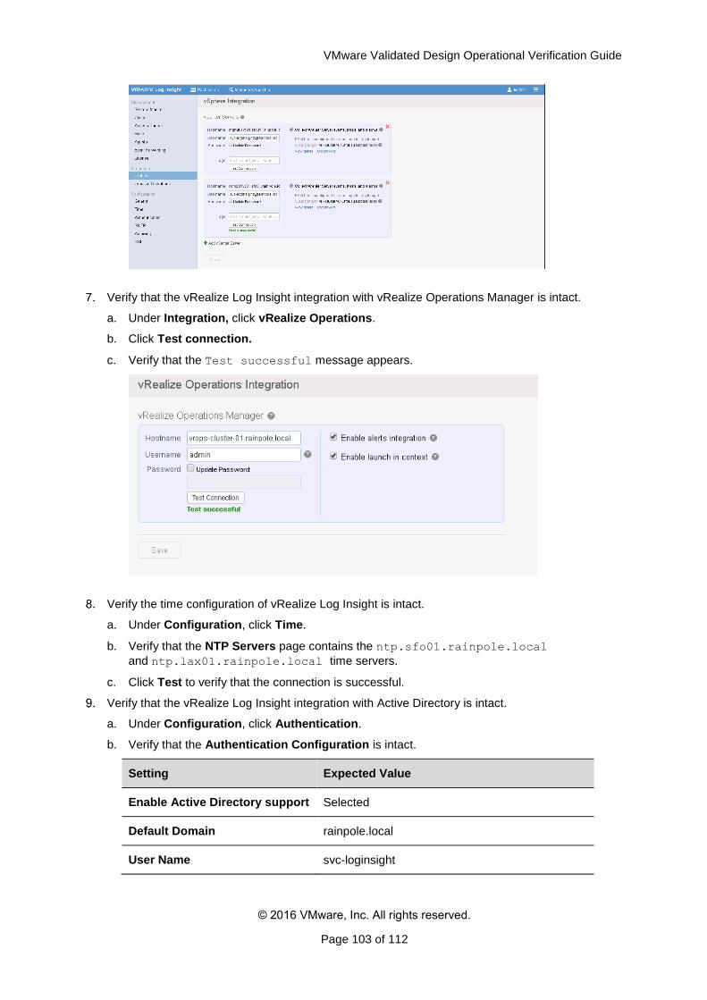
VMware Validated Design Operational Verification Guide
© 2016 VMware, Inc. All rights reserved.
Page 103 of 112
Verify that the vRealize Log Insight integration with vRealize Operations Manager is intact.
a. Under Integration, click vRealize Operations.
b. Click Test connection.
c. Verify that the Test successful message appears.
Verify the time configuration of vRealize Log Insight is intact.
a. Under Configuration, click Time.
b. Verify that the NTP Servers page contains the ntp.sfo01.rainpole.local
and ntp.lax01.rainpole.local time servers.
c. Click Test to verify that the connection is successful.
Verify that the vRealize Log Insight integration with Active Directory is intact.
a. Under Configuration, click Authentication.
b. Verify that the Authentication Configuration is intact.
Setting Expected Value
Enable Active Directory support Selected
Default Domain rainpole.local
User Name svc-loginsight
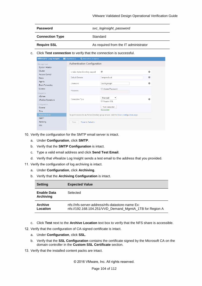
VMware Validated Design Operational Verification Guide
© 2016 VMware, Inc. All rights reserved.
Page 104 of 112
Password svc_loginsight_password
Connection Type Standard
Require SSL As required from the IT administrator
c. Click Test connection to verify that the connection is successful.
Verify the configuration for the SMTP email server is intact.
a. Under Configuration, click SMTP.
b. Verify that the SMTP Configuration is intact.
c. Type a valid email address and click Send Test Email.
d. Verify that vRealize Log Insight sends a test email to the address that you provided.
Verify the configuration of log archiving is intact.
a. Under Configuration, click Archiving.
b. Verify that the Archiving Configuration is intact.
Setting Expected Value
Enable Data Archiving
Selected
Archive Location
nfs://nfs-server-address/nfs-datastore-name Ex: nfs://192.168.104.251/VVD_Demand_MgmtA_1TB for Region A
c. Click Test next to the Archive Location text box to verify that the NFS share is accessible.
Verify that the configuration of CA-signed certificate is intact.
a. Under Configuration, click SSL.
b. Verify that the SSL Configuration contains the certificate signed by the Microsoft CA on the domain controller in the Custom SSL Certificate section.
Verify that the installed content packs are intact.
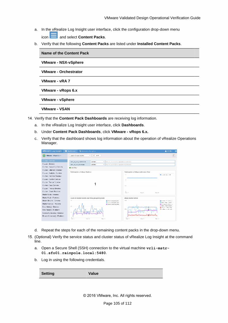
VMware Validated Design Operational Verification Guide
© 2016 VMware, Inc. All rights reserved.
Page 105 of 112
a. In the vRealize Log Insight user interface, click the configuration drop-down menu
icon and select Content Packs.
b. Verify that the following Content Packs are listed under Installed Content Packs.
Name of the Content Pack
VMware - NSX-vSphere
VMware - Orchestrator
VMware - vRA 7
VMware - vRops 6.x
VMware - vSphere
VMware - VSAN
Verify that the Content Pack Dashboards are receiving log information.
a. In the vRealize Log Insight user interface, click Dashboards.
b. Under Content Pack Dashboards, click VMware - vRops 6.x.
c. Verify that the dashboard shows log information about the operation of vRealize Operations Manager.
d. Repeat the steps for each of the remaining content packs in the drop-down menu.
(Optional) Verify the service status and cluster status of vRealize Log Insight at the command line.
a. Open a Secure Shell (SSH) connection to the virtual machine vrli-mstr-
01.sfo01.rainpole.local:5480.
b. Log in using the following credentials.
Setting Value
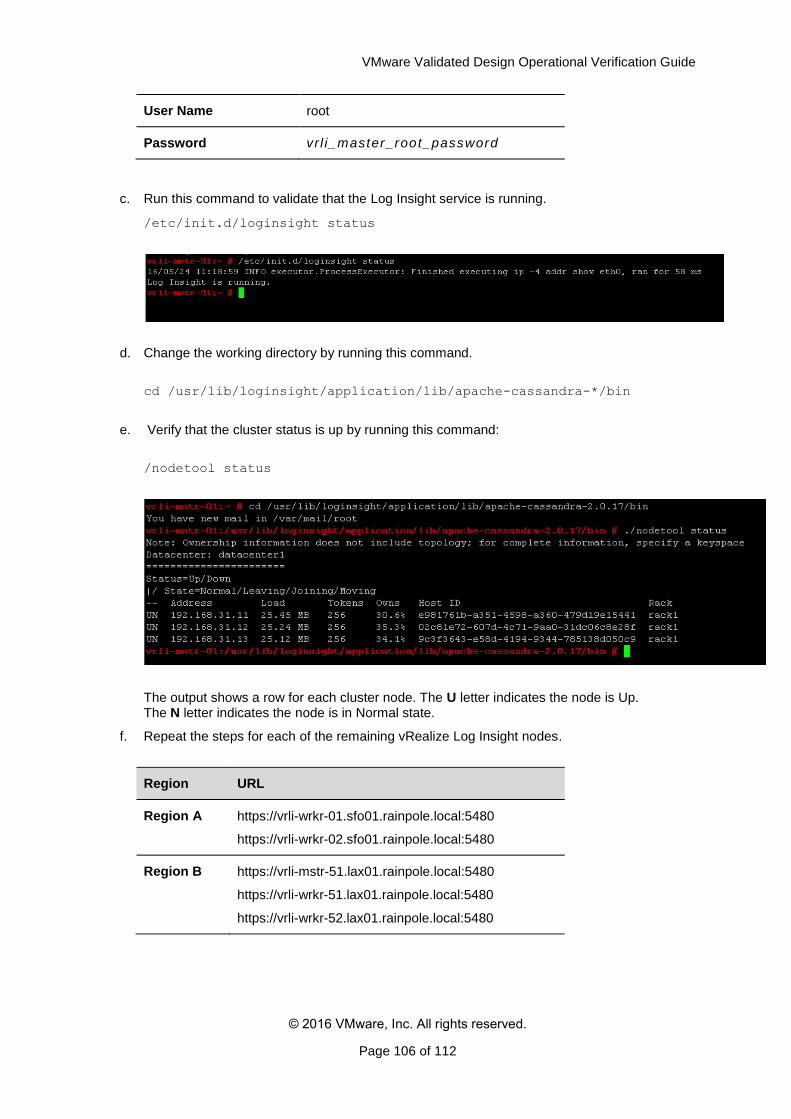
VMware Validated Design Operational Verification Guide
© 2016 VMware, Inc. All rights reserved.
Page 106 of 112
User Name root
Password vr l i_master_root_password
c. Run this command to validate that the Log Insight service is running.
/etc/init.d/loginsight status
d. Change the working directory by running this command.
cd /usr/lib/loginsight/application/lib/apache-cassandra-*/bin
e. Verify that the cluster status is up by running this command:
/nodetool status
The output shows a row for each cluster node. The U letter indicates the node is Up. The N letter indicates the node is in Normal state.
f. Repeat the steps for each of the remaining vRealize Log Insight nodes.
Region URL
Region A https://vrli-wrkr-01.sfo01.rainpole.local:5480
https://vrli-wrkr-02.sfo01.rainpole.local:5480
Region B https://vrli-mstr-51.lax01.rainpole.local:5480
https://vrli-wrkr-51.lax01.rainpole.local:5480
https://vrli-wrkr-52.lax01.rainpole.local:5480
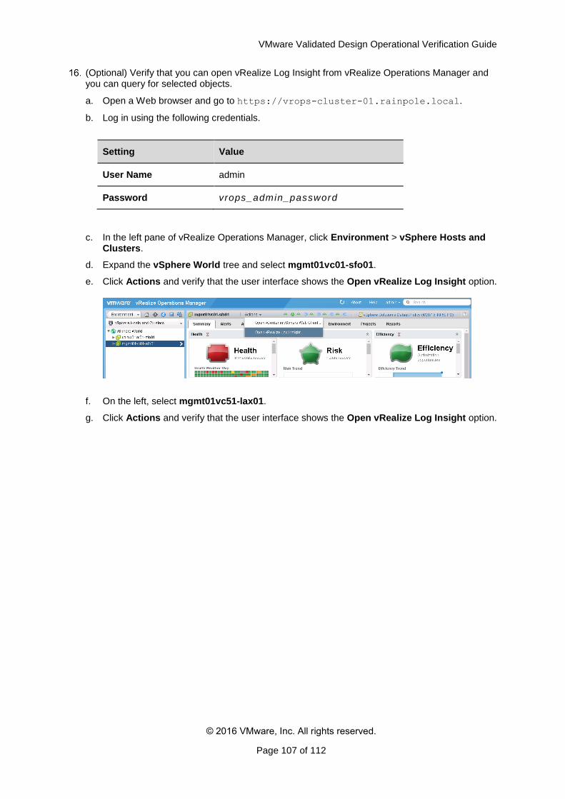
VMware Validated Design Operational Verification Guide
© 2016 VMware, Inc. All rights reserved.
Page 107 of 112
(Optional) Verify that you can open vRealize Log Insight from vRealize Operations Manager and you can query for selected objects.
a. Open a Web browser and go to https://vrops-cluster-01.rainpole.local.
b. Log in using the following credentials.
Setting Value
User Name admin
Password vrops_admin_password
c. In the left pane of vRealize Operations Manager, click Environment > vSphere Hosts and Clusters.
d. Expand the vSphere World tree and select mgmt01vc01-sfo01.
e. Click Actions and verify that the user interface shows the Open vRealize Log Insight option.
f. On the left, select mgmt01vc51-lax01.
g. Click Actions and verify that the user interface shows the Open vRealize Log Insight option.
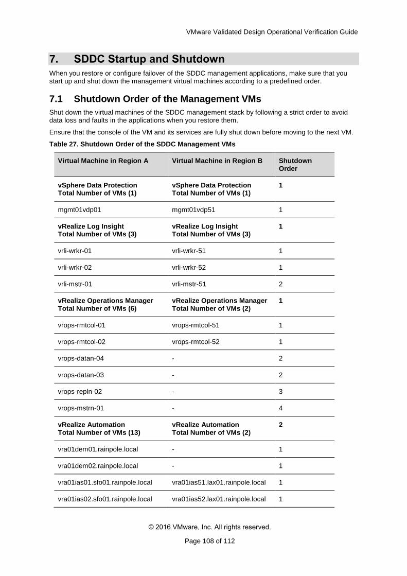
VMware Validated Design Operational Verification Guide
© 2016 VMware, Inc. All rights reserved.
Page 108 of 112
7. SDDC Startup and Shutdown
When you restore or configure failover of the SDDC management applications, make sure that you start up and shut down the management virtual machines according to a predefined order.
7.1 Shutdown Order of the Management VMs
Shut down the virtual machines of the SDDC management stack by following a strict order to avoid data loss and faults in the applications when you restore them.
Ensure that the console of the VM and its services are fully shut down before moving to the next VM.
Table 27. Shutdown Order of the SDDC Management VMs
Virtual Machine in Region A Virtual Machine in Region B Shutdown Order
vSphere Data Protection Total Number of VMs (1)
vSphere Data Protection Total Number of VMs (1)
1
mgmt01vdp01 mgmt01vdp51 1
vRealize Log Insight Total Number of VMs (3)
vRealize Log Insight Total Number of VMs (3)
1
vrli-wrkr-01 vrli-wrkr-51 1
vrli-wrkr-02 vrli-wrkr-52 1
vrli-mstr-01 vrli-mstr-51 2
vRealize Operations Manager Total Number of VMs (6)
vRealize Operations Manager Total Number of VMs (2)
1
vrops-rmtcol-01 vrops-rmtcol-51 1
vrops-rmtcol-02 vrops-rmtcol-52 1
vrops-datan-04 - 2
vrops-datan-03 - 2
vrops-repln-02 - 3
vrops-mstrn-01 - 4
vRealize Automation Total Number of VMs (13)
vRealize Automation Total Number of VMs (2)
2
vra01dem01.rainpole.local - 1
vra01dem02.rainpole.local - 1
vra01ias01.sfo01.rainpole.local vra01ias51.lax01.rainpole.local 1
vra01ias02.sfo01.rainpole.local vra01ias52.lax01.rainpole.local 1
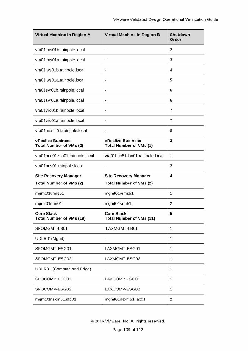
VMware Validated Design Operational Verification Guide
© 2016 VMware, Inc. All rights reserved.
Page 109 of 112
Virtual Machine in Region A Virtual Machine in Region B Shutdown Order
vra01ims01b.rainpole.local - 2
vra01ims01a.rainpole.local - 3
vra01iws01b.rainpole.local - 4
vra01iws01a.rainpole.local - 5
vra01svr01b.rainpole.local - 6
vra01svr01a.rainpole.local - 6
vra01vro01b.rainpole.local - 7
vra01vro01a.rainpole.local - 7
vra01mssql01.rainpole.local - 8
vRealize Business Total Number of VMs (2)
vRealize Business Total Number of VMs (1)
3
vra01buc01.sfo01.rainpole.local vra01buc51.lax01.rainpole.local 1
vra01bus01.rainpole.local - 2
Site Recovery Manager
Total Number of VMs (2)
Site Recovery Manager
Total Number of VMs (2)
4
mgmt01vrms01 mgmt01vrms51 1
mgmt01srm01 mgmt01srm51 2
Core Stack Total Number of VMs (19)
Core Stack Total Number of VMs (11)
5
SFOMGMT-LB01 LAXMGMT-LB01 1
UDLR01(Mgmt) - 1
SFOMGMT-ESG01 LAXMGMT-ESG01 1
SFOMGMT-ESG02 LAXMGMT-ESG02 1
UDLR01 (Compute and Edge) - 1
SFOCOMP-ESG01 LAXCOMP-ESG01 1
SFOCOMP-ESG02 LAXCOMP-ESG02 1
mgmt01nsxm01.sfo01 mgmt01nsxm51.lax01 2
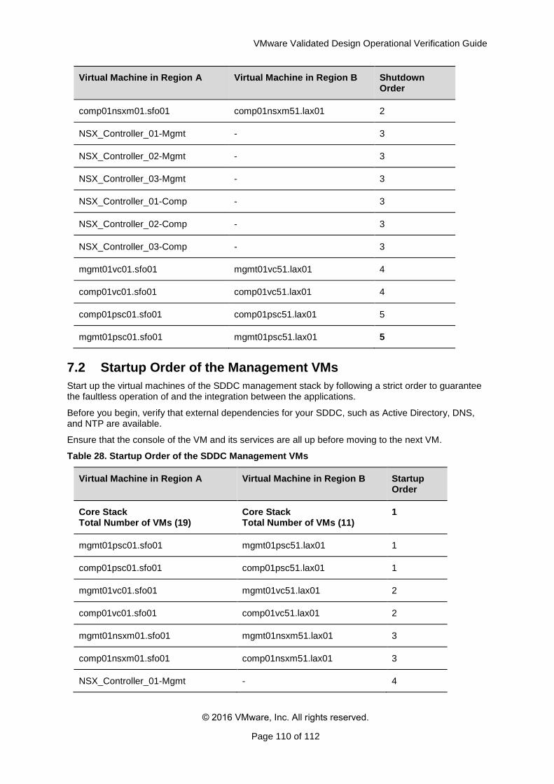
VMware Validated Design Operational Verification Guide
© 2016 VMware, Inc. All rights reserved.
Page 110 of 112
Virtual Machine in Region A Virtual Machine in Region B Shutdown Order
comp01nsxm01.sfo01 comp01nsxm51.lax01 2
NSX_Controller_01-Mgmt - 3
NSX_Controller_02-Mgmt - 3
NSX_Controller_03-Mgmt - 3
NSX_Controller_01-Comp - 3
NSX_Controller_02-Comp - 3
NSX_Controller_03-Comp - 3
mgmt01vc01.sfo01 mgmt01vc51.lax01 4
comp01vc01.sfo01 comp01vc51.lax01 4
comp01psc01.sfo01 comp01psc51.lax01 5
mgmt01psc01.sfo01 mgmt01psc51.lax01 5
7.2 Startup Order of the Management VMs
Start up the virtual machines of the SDDC management stack by following a strict order to guarantee the faultless operation of and the integration between the applications.
Before you begin, verify that external dependencies for your SDDC, such as Active Directory, DNS, and NTP are available.
Ensure that the console of the VM and its services are all up before moving to the next VM.
Table 28. Startup Order of the SDDC Management VMs
Virtual Machine in Region A Virtual Machine in Region B Startup Order
Core Stack Total Number of VMs (19)
Core Stack Total Number of VMs (11)
1
mgmt01psc01.sfo01 mgmt01psc51.lax01 1
comp01psc01.sfo01 comp01psc51.lax01 1
mgmt01vc01.sfo01 mgmt01vc51.lax01 2
comp01vc01.sfo01 comp01vc51.lax01 2
mgmt01nsxm01.sfo01 mgmt01nsxm51.lax01 3
comp01nsxm01.sfo01 comp01nsxm51.lax01 3
NSX_Controller_01-Mgmt - 4
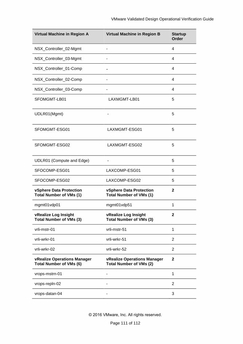
VMware Validated Design Operational Verification Guide
© 2016 VMware, Inc. All rights reserved.
Page 111 of 112
Virtual Machine in Region A Virtual Machine in Region B Startup Order
NSX_Controller_02-Mgmt - 4
NSX_Controller_03-Mgmt - 4
NSX_Controller_01-Comp - 4
NSX_Controller_02-Comp - 4
NSX_Controller_03-Comp - 4
SFOMGMT-LB01 LAXMGMT-LB01 5
UDLR01(Mgmt) - 5
SFOMGMT-ESG01 LAXMGMT-ESG01 5
SFOMGMT-ESG02 LAXMGMT-ESG02 5
UDLR01 (Compute and Edge) - 5
SFOCOMP-ESG01 LAXCOMP-ESG01 5
SFOCOMP-ESG02 LAXCOMP-ESG02 5
vSphere Data Protection Total Number of VMs (1)
vSphere Data Protection Total Number of VMs (1)
2
mgmt01vdp01 mgmt01vdp51 1
vRealize Log Insight Total Number of VMs (3)
vRealize Log Insight Total Number of VMs (3)
2
vrli-mstr-01 vrli-mstr-51 1
vrli-wrkr-01 vrli-wrkr-51 2
vrli-wrkr-02 vrli-wrkr-52 2
vRealize Operations Manager Total Number of VMs (6)
vRealize Operations Manager Total Number of VMs (2)
2
vrops-mstrn-01 - 1
vrops-repln-02 - 2
vrops-datan-04 - 3
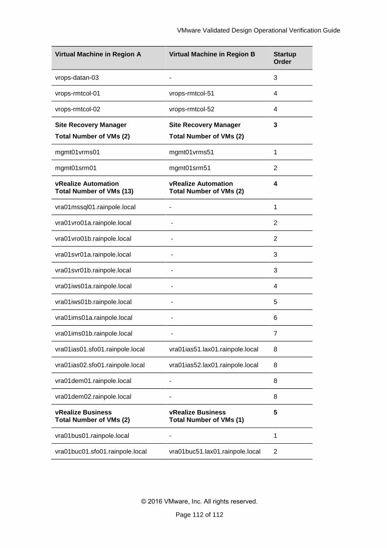
VMware Validated Design Operational Verification Guide
© 2016 VMware, Inc. All rights reserved.
Page 112 of 112
Virtual Machine in Region A Virtual Machine in Region B Startup Order
vrops-datan-03 - 3
vrops-rmtcol-01 vrops-rmtcol-51 4
vrops-rmtcol-02 vrops-rmtcol-52 4
Site Recovery Manager
Total Number of VMs (2)
Site Recovery Manager
Total Number of VMs (2)
3
mgmt01vrms01 mgmt01vrms51 1
mgmt01srm01 mgmt01srm51 2
vRealize Automation Total Number of VMs (13)
vRealize Automation Total Number of VMs (2)
4
vra01mssql01.rainpole.local - 1
vra01vro01a.rainpole.local - 2
vra01vro01b.rainpole.local - 2
vra01svr01a.rainpole.local - 3
vra01svr01b.rainpole.local - 3
vra01iws01a.rainpole.local - 4
vra01iws01b.rainpole.local - 5
vra01ims01a.rainpole.local - 6
vra01ims01b.rainpole.local - 7
vra01ias01.sfo01.rainpole.local vra01ias51.lax01.rainpole.local 8
vra01ias02.sfo01.rainpole.local vra01ias52.lax01.rainpole.local 8
vra01dem01.rainpole.local - 8
vra01dem02.rainpole.local - 8
vRealize Business Total Number of VMs (2)
vRealize Business Total Number of VMs (1)
5
vra01bus01.rainpole.local - 1
vra01buc01.sfo01.rainpole.local vra01buc51.lax01.rainpole.local 2