Embed Size (px)
Citation preview
Architecture and DesignModified on 21 DEC 2017VMware Validated Design 4.1VMware Validated Design for Micro-Segmentation 4.1
Architecture and Design
VMware, Inc. 2
You can find the most up-to-date technical documentation on the VMware website at:
https://docs.vmware.com/
If you have comments about this documentation, submit your feedback to
Copyright © 2016, 2017 VMware, Inc. All rights reserved. Copyright and trademark information.
VMware, Inc.3401 Hillview Ave.Palo Alto, CA 94304www.vmware.com
Contents
About Architecture and Design for VMware Validated Design for Micro-Segmentation 4
1 Architecture Overview 6
2 Physical Infrastructure Architecture 9
Pod Architecture 9
Pod Types 10
Physical Network Architecture 12
Availability Zones and Regions 18
3 Virtual Infrastructure Architecture 20
Virtual Infrastructure Overview 20
Network Virtualization Components 22
Network Virtualization Services 23
4 Operations Architecture Overview 27
Logging Architecture 27
5 Detailed Design 34
6 Physical Infrastructure Design 35
Physical Design Fundamentals 36
Physical Networking Design 40
Physical Storage Design 47
7 Virtual Infrastructure Design 56
ESXi Design 58
vCenter Server Design 61
vSphere Cluster Design 66
vCenter Server Customization 71
Use of Transport Layer Security (TLS) Certificates 73
Virtualization Network Design 74
NSX Design 89
Shared Storage Design 111
8 Operations Infrastructure Design 131
vRealize Log Insight Design 131
VMware, Inc. 3
About Architecture and Design forVMware Validated Design for Micro-Segmentation
The Architecture and Design document for the VMware Validated Design for Micro-Segmentation usecase contains a validated model of the use case and provides a detailed design of each component.
The document discusses the building blocks and the main principles of each layer and provides theavailable design options according to the design objective. A set of design decisions clearly lays out thedecisions that were made and includes justification and potential implementation of each decision.
See the Planning and Preparation document for the VMware Validated Design for Micro-Segmentation formore information about supported product versions.
Note Design decisions in this document are based on design decisions in the Architecture and Designdocument for the VMware Validated Design for the Software-Defined Data Center, but some decisionhave been removed or changed. As a result, the decisions are not always numbered consecutively.
Intended AudienceThe Architecture and Design document is intended for cloud architects, infrastructure administrators andcloud administrators who are familiar with and want to use VMware software to deploy in a short time andmanage an SDDC that meets the requirements for capacity, scalability, backup and restore, andextensibility for disaster recovery support.
VMware Validated Design for the SDDC and this Use CaseDocumentationFor details on product deployment, see the sections on vSphere, NSX and vRealize LogInsight in theVMware Validated Design for Software-Defined Data Center Deployment for Region A documentation.After initial deployment, the product documentation for vSphere and for NSX for vSphere enables you toset up your environment. Because this documentation is already available, the Validated Design forMicro-Segmentation does not include detailed step-by-step instructions for each task.
Some of the information in this guide, in particular illustrations, show a dual-region design or includeVMware vSAN.
VMware, Inc. 4
The Validated Design for Micro-Segmentation is a single-region design that does not include VMwarevSAN. However, this design uses the vRealize Log Insight design from the VMware Validated Design forthe SDDC. Because of that, vRealize Log Insight uses two regions.
This design can be expanded to use vSAN or to use two regions for all components.
Architecture and Design
VMware, Inc. 5
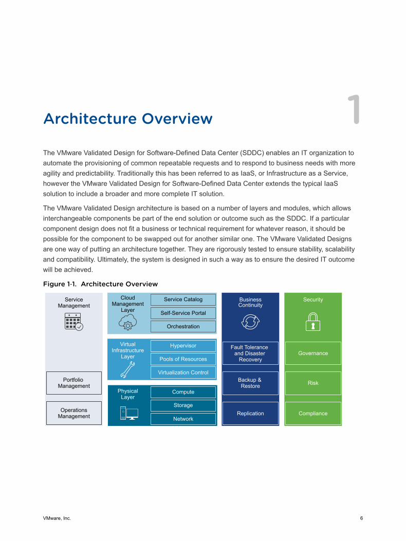
Architecture Overview 1The VMware Validated Design for Software-Defined Data Center (SDDC) enables an IT organization toautomate the provisioning of common repeatable requests and to respond to business needs with moreagility and predictability. Traditionally this has been referred to as IaaS, or Infrastructure as a Service,however the VMware Validated Design for Software-Defined Data Center extends the typical IaaSsolution to include a broader and more complete IT solution.
The VMware Validated Design architecture is based on a number of layers and modules, which allowsinterchangeable components be part of the end solution or outcome such as the SDDC. If a particularcomponent design does not fit a business or technical requirement for whatever reason, it should bepossible for the component to be swapped out for another similar one. The VMware Validated Designsare one way of putting an architecture together. They are rigorously tested to ensure stability, scalabilityand compatibility. Ultimately, the system is designed in such a way as to ensure the desired IT outcomewill be achieved.
Figure 1‑1. Architecture Overview
ServiceManagement
Portfolio Management
OperationsManagement
CloudManagement
Layer
Service Catalog
Self-Service Portal
Orchestration
BusinessContinuity
Fault Tolerance and Disaster
Recovery
Backup & Restore
Hypervisor
Pools of Resources
Virtualization Control
VirtualInfrastructure
Layer
Compute
Storage
Network
PhysicalLayer
Security
Replication Compliance
Risk
Governance
VMware, Inc. 6
Physical LayerThe lowest layer of the solution is the Physical Layer, sometimes referred to as the core layer, whichconsists of the compute, network and storage components. Inside the compute component sit the x86based servers that run the management, edge and tenant compute workloads. This design gives someguidance for the physical capabilities required to run this architecture, but does not makerecommendations for a specific type or brand of hardware.
Note All components must be supported. See the VMware Compatibility Guide.
Virtual Infrastructure LayerThe Virtual Infrastructure Layer sits on top of the Physical Layer components. The Virtual InfrastructureLayer controls access to the underlying physical infrastructure is controlled and allocates resources to themanagement and tenant workloads. The management workloads consist of elements in the virtualmanagement layer itself, along with elements in the Cloud Management Layer, Service Management,Business Continuity and Security areas.
Cloud Management LayerThe Cloud Management Layer is the top layer of the stack. Service consumption occurs at this layer.
This layer calls for resources and orchestrates the actions of the lower layers, most commonly by meansof a user interface or application programming interface (API). While the SDDC can stand on its ownwithout other ancillary services, other supporting components are needed for a complete SDDCexperience. The Service Management, Business Continuity and Security areas complete the architectureby providing this support.
Service ManagementWhen building any type of IT infrastructure, portfolio and operations management play key roles incontinuous day-to-day service delivery. The Service Management area of this architecture mainly focuseson operations management, in particular monitoring, alerting and log management.
Operations ManagementThe architecture of the operations management layer includes management components that providesupport for the main types of operations in an SDDC. For the micro-segmentation use case, you canperform monitoring, logging with vRealize Log Insight.
Architecture and Design
VMware, Inc. 7
Within the operations layer, the underlying physical infrastructure and the virtual management and tenantworkloads are monitored in real-time. Information is collected in the form of structured data (metrics) andunstructured data (logs). The operations layer also knows about the SDDC topology, that is physical andvirtual compute, networking, and storage resources, which are key in intelligent and dynamic operationalmanagement. The operations layer consists primarily of monitoring, logging, backup and restore, disasterrecovery and security compliance adherence. Together, these components ensure that servicemanagement, business continuity, and security areas are met.
Business ContinuityAn enterprise-ready system must contain elements to support business continuity by providing databackup, restoration, and disaster recovery. When data loss occurs, the right elements must be in place toprevent permanent loss to the business. This design provides comprehensive guidance on how tooperate backup and restore functions, and includes run books with detailed information on how to failover components in the event of a disaster.
SecurityAll systems need to be secure by design. A secure design reduces risk and increases compliance whileproviding a governance structure. The security area outlines what is needed to ensure the entire SDDC isresilient to both internal and external threats.
Architecture and Design
VMware, Inc. 8
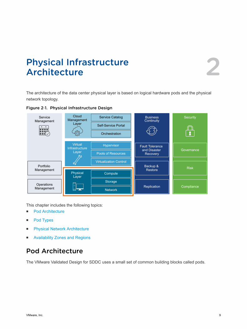
Physical InfrastructureArchitecture 2The architecture of the data center physical layer is based on logical hardware pods and the physicalnetwork topology.
Figure 2‑1. Physical Infrastructure Design
ServiceManagement
Portfolio Management
OperationsManagement
CloudManagement
Layer
Service Catalog
Self-Service Portal
Orchestration
BusinessContinuity
Fault Tolerance and Disaster
Recovery
Backup & Restore
Hypervisor
Pools of Resources
Virtualization Control
VirtualInfrastructure
Layer
Compute
Storage
Network
PhysicalLayer
Security
Replication Compliance
Risk
Governance
This chapter includes the following topics:n Pod Architecture
n Pod Types
n Physical Network Architecture
n Availability Zones and Regions
Pod ArchitectureThe VMware Validated Design for SDDC uses a small set of common building blocks called pods.
VMware, Inc. 9
Pod Architecture CharacteristicsPods can include different combinations of servers, storage equipment, and network equipment, and canbe set up with varying levels of hardware redundancy and varying quality of components. Pods areconnected to a network core that distributes data between them. The pod is not defined by any hardphysical properties, as it is a standard unit of connected elements within the SDDC network fabric.
A pod is a logical boundary of functionality for the SDDC platform. While each pod usually spans onerack, it is possible to aggregate multiple pods into a single rack in smaller setups. For both small andlarge setups, homogeneity and easy replication are important.
Different pods of the same type can provide different characteristics for varying requirements. Forexample, one compute pod could use full hardware redundancy for each component (power supplythrough memory chips) for increased availability. At the same time, another compute pod in the samesetup could use low-cost hardware without any hardware redundancy. With these variations, thearchitecture can cater to the different workload requirements in the SDDC.
One of the guiding principles for such deployments is that VLANs are not spanned beyond a single podby the network virtualization layer. Although this VLAN restriction appears to be a simple requirement, ithas widespread impact on how a physical switching infrastructure can be built and on how it scales.
Pod to Rack MappingPods are not mapped one-to-one to data center racks. While a pod is an atomic unit of a repeatablebuilding block, a rack is merely a unit of size. Because pods can have different sizes, how pods aremapped to data center racks depends on the use case.
One Pod in One Rack One pod can occupy exactly one rack.
Multiple Pods in OneRack
Two or more pods can occupy a single rack, for example, one managementpod and one shared edge and compute pod can be deployed to a singlerack.
Single Pod AcrossMultiple Racks
A single pod can stretch across multiple adjacent racks. For example, astorage pod with filer heads and disk shelves can span more than one rackor a compute pod that has more host then a single rack can support.
Note The management and the shared edge and compute pods cannot span racks. This is due to NSXcontrollers, and other virtual machines, on a VLAN backed network migrating to a different rack wherethat IP subnet is not available due to layer 2 termination at the Top of Rack (ToR) switch.
Pod TypesThe SDDC differentiates between different types of pods including management pod, compute pod, edgepod, shared edge and compute pod, and storage pod. Each design includes several pods.
Architecture and Design
VMware, Inc. 10
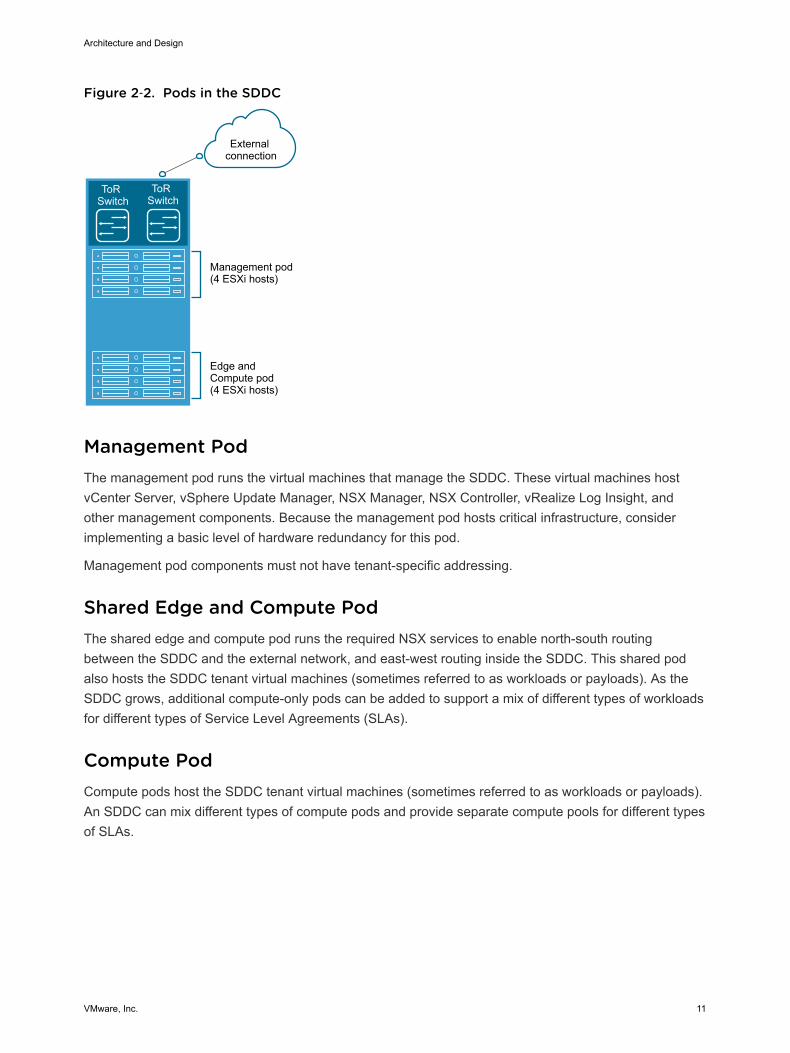
Figure 2‑2. Pods in the SDDC
ToR Switch
ToR Switch
Management pod(4 ESXi hosts)
Edge and Compute pod(4 ESXi hosts)
External connection
Management PodThe management pod runs the virtual machines that manage the SDDC. These virtual machines hostvCenter Server, vSphere Update Manager, NSX Manager, NSX Controller, vRealize Log Insight, andother management components. Because the management pod hosts critical infrastructure, considerimplementing a basic level of hardware redundancy for this pod.
Management pod components must not have tenant-specific addressing.
Shared Edge and Compute PodThe shared edge and compute pod runs the required NSX services to enable north-south routingbetween the SDDC and the external network, and east-west routing inside the SDDC. This shared podalso hosts the SDDC tenant virtual machines (sometimes referred to as workloads or payloads). As theSDDC grows, additional compute-only pods can be added to support a mix of different types of workloadsfor different types of Service Level Agreements (SLAs).
Compute PodCompute pods host the SDDC tenant virtual machines (sometimes referred to as workloads or payloads).An SDDC can mix different types of compute pods and provide separate compute pools for different typesof SLAs.
Architecture and Design
VMware, Inc. 11
Storage PodStorage pods provide network-accessible storage using NFS or iSCSI. Different types of storage podscan provide different levels of SLA, ranging from just a bunch of disks (JBODs) using IDE drives withminimal to no redundancy, to fully redundant enterprise-class storage arrays. For bandwidth-intense IP-based storage, the bandwidth of these pods can scale dynamically.
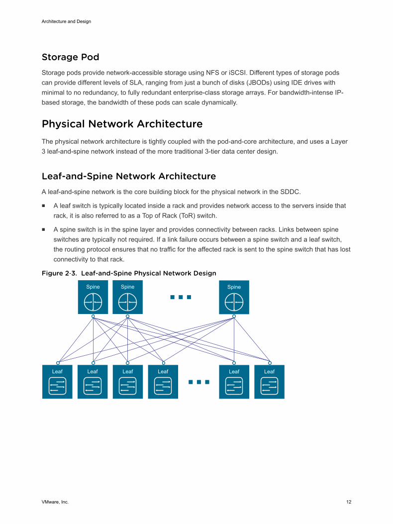
Physical Network ArchitectureThe physical network architecture is tightly coupled with the pod-and-core architecture, and uses a Layer3 leaf-and-spine network instead of the more traditional 3-tier data center design.
Leaf-and-Spine Network ArchitectureA leaf-and-spine network is the core building block for the physical network in the SDDC.
n A leaf switch is typically located inside a rack and provides network access to the servers inside thatrack, it is also referred to as a Top of Rack (ToR) switch.
n A spine switch is in the spine layer and provides connectivity between racks. Links between spineswitches are typically not required. If a link failure occurs between a spine switch and a leaf switch,the routing protocol ensures that no traffic for the affected rack is sent to the spine switch that has lostconnectivity to that rack.
Figure 2‑3. Leaf-and-Spine Physical Network Design
Leaf Leaf Leaf Leaf Leaf Leaf
Spine Spine Spine
Architecture and Design
VMware, Inc. 12
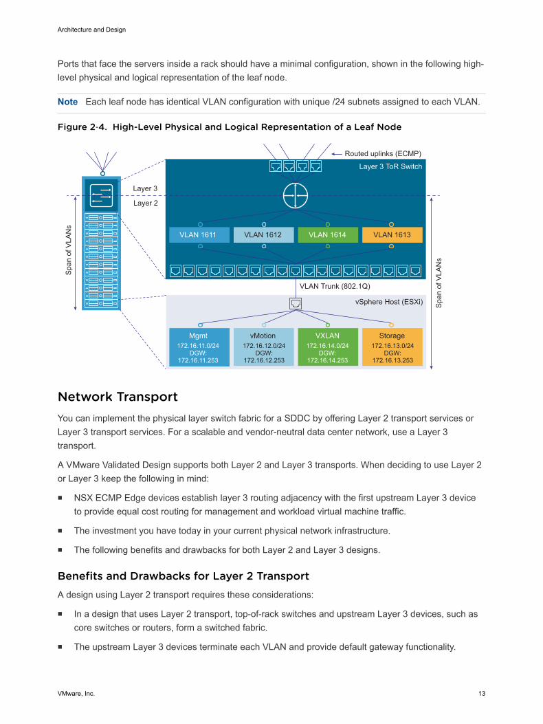
Ports that face the servers inside a rack should have a minimal configuration, shown in the following high-level physical and logical representation of the leaf node.
Note Each leaf node has identical VLAN configuration with unique /24 subnets assigned to each VLAN.
Figure 2‑4. High-Level Physical and Logical Representation of a Leaf Node
Span
of V
LAN
s
Layer 3 ToR Switch
Layer 2
Layer 3
VLAN 1612 VLAN 1614 VLAN 1613VLAN 1611
VLAN Trunk (802.1Q)
vMotion VXLAN StorageMgmt172.16.11.0/24
DGW:172.16.11.253
172.16.12.0/24DGW:
172.16.12.253
172.16.13.0/24DGW:
172.16.13.253
172.16.14.0/24DGW:
172.16.14.253
Span
of V
LAN
s
vSphere Host (ESXi)
Routed uplinks (ECMP)
Network TransportYou can implement the physical layer switch fabric for a SDDC by offering Layer 2 transport services orLayer 3 transport services. For a scalable and vendor-neutral data center network, use a Layer 3transport.
A VMware Validated Design supports both Layer 2 and Layer 3 transports. When deciding to use Layer 2or Layer 3 keep the following in mind:
n NSX ECMP Edge devices establish layer 3 routing adjacency with the first upstream Layer 3 deviceto provide equal cost routing for management and workload virtual machine traffic.
n The investment you have today in your current physical network infrastructure.
n The following benefits and drawbacks for both Layer 2 and Layer 3 designs.
Benefits and Drawbacks for Layer 2 TransportA design using Layer 2 transport requires these considerations:
n In a design that uses Layer 2 transport, top-of-rack switches and upstream Layer 3 devices, such ascore switches or routers, form a switched fabric.
n The upstream Layer 3 devices terminate each VLAN and provide default gateway functionality.
Architecture and Design
VMware, Inc. 13
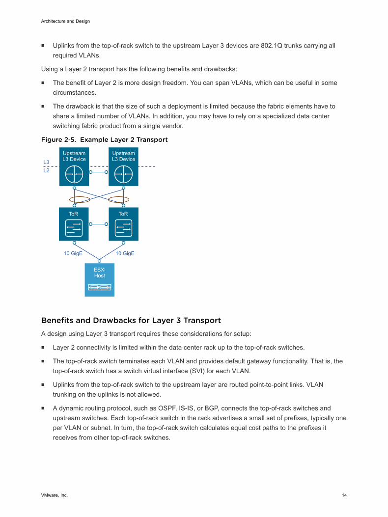
n Uplinks from the top-of-rack switch to the upstream Layer 3 devices are 802.1Q trunks carrying allrequired VLANs.
Using a Layer 2 transport has the following benefits and drawbacks:
n The benefit of Layer 2 is more design freedom. You can span VLANs, which can be useful in somecircumstances.
n The drawback is that the size of such a deployment is limited because the fabric elements have toshare a limited number of VLANs. In addition, you may have to rely on a specialized data centerswitching fabric product from a single vendor.
Figure 2‑5. Example Layer 2 Transport
ToR ToR
ESXiHost
Upstream L3 DeviceL3
10 GigE 10 GigE
L2
Upstream L3 Device
Benefits and Drawbacks for Layer 3 TransportA design using Layer 3 transport requires these considerations for setup:
n Layer 2 connectivity is limited within the data center rack up to the top-of-rack switches.
n The top-of-rack switch terminates each VLAN and provides default gateway functionality. That is, thetop-of-rack switch has a switch virtual interface (SVI) for each VLAN.
n Uplinks from the top-of-rack switch to the upstream layer are routed point-to-point links. VLANtrunking on the uplinks is not allowed.
n A dynamic routing protocol, such as OSPF, IS-IS, or BGP, connects the top-of-rack switches andupstream switches. Each top-of-rack switch in the rack advertises a small set of prefixes, typically oneper VLAN or subnet. In turn, the top-of-rack switch calculates equal cost paths to the prefixes itreceives from other top-of-rack switches.
Architecture and Design
VMware, Inc. 14
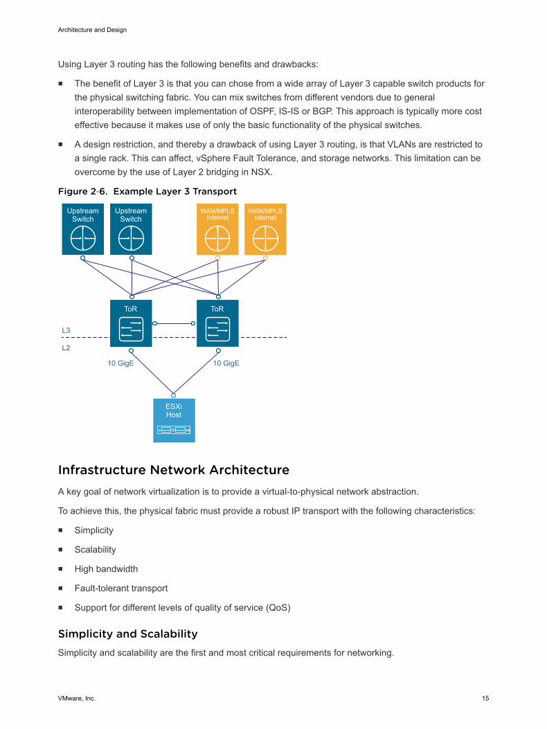
Using Layer 3 routing has the following benefits and drawbacks:
n The benefit of Layer 3 is that you can chose from a wide array of Layer 3 capable switch products forthe physical switching fabric. You can mix switches from different vendors due to generalinteroperability between implementation of OSPF, IS-IS or BGP. This approach is typically more costeffective because it makes use of only the basic functionality of the physical switches.
n A design restriction, and thereby a drawback of using Layer 3 routing, is that VLANs are restricted toa single rack. This can affect, vSphere Fault Tolerance, and storage networks. This limitation can beovercome by the use of Layer 2 bridging in NSX.
Figure 2‑6. Example Layer 3 Transport
ToR
L3
ESXiHost
UpstreamSwitch
UpstreamSwitch
WAN/MPLSInternet
WAN/MPLSInternet
ToR
L2
10 GigE10 GigE
Infrastructure Network ArchitectureA key goal of network virtualization is to provide a virtual-to-physical network abstraction.
To achieve this, the physical fabric must provide a robust IP transport with the following characteristics:
n Simplicity
n Scalability
n High bandwidth
n Fault-tolerant transport
n Support for different levels of quality of service (QoS)
Simplicity and ScalabilitySimplicity and scalability are the first and most critical requirements for networking.
Architecture and Design
VMware, Inc. 15
Simplicity
Configuration of the switches inside a data center must be simple. General or global configuration suchas AAA, SNMP, syslog, NTP, and others should be replicated line by line, independent of the position ofthe switches. A central management capability to configure all switches at once is an alternative.
Configurations that are unique to the switches such as multi-chassis link aggregation groups, VLAN IDs,and dynamic routing protocol configuration, should be kept to a minimum.
Scalability
Scalability factors include, but are not limited to, the following:
n Number of racks supported in a fabric.
n Amount of bandwidth between any two racks in a data center.
n Number of paths between racks.
The total number of ports available across all switches and the oversubscription that is acceptabledetermine the number of racks supported in a fabric. Different racks may host different types ofinfrastructure, which can result in different bandwidth requirements.
n Racks with IP storage systems might attract or source more traffic than other racks.
n Compute racks, such as racks hosting hypervisors with workloads or virtual machines, might havedifferent bandwidth requirements than shared edge and compute racks, which provide connectivity tothe outside world.
Link speed and the number of links vary to satisfy different bandwidth demands. You can vary them foreach rack.
Quality of Service DifferentiationVirtualized environments carry different types of traffic, including tenant, storage and management traffic,across the switching infrastructure. Each traffic type has different characteristics and makes differentdemands on the physical switching infrastructure.
n Management traffic, although typically low in volume, is critical for controlling physical and virtualnetwork state.
n IP storage traffic is typically high in volume and generally stays within a data center.
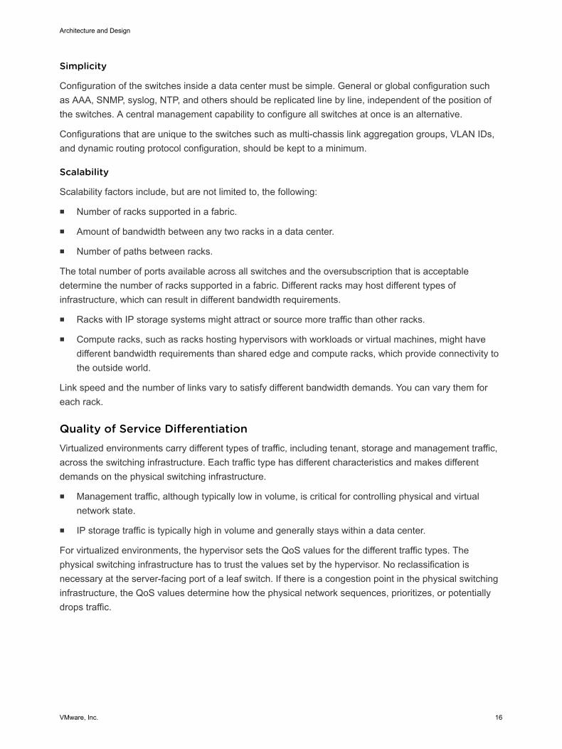
For virtualized environments, the hypervisor sets the QoS values for the different traffic types. Thephysical switching infrastructure has to trust the values set by the hypervisor. No reclassification isnecessary at the server-facing port of a leaf switch. If there is a congestion point in the physical switchinginfrastructure, the QoS values determine how the physical network sequences, prioritizes, or potentiallydrops traffic.
Architecture and Design
VMware, Inc. 16
Figure 2‑7. Quality of Service Trust Point
VM
Leaf
Trust or Set DSCP and CoS
Trust DSCP and CoS
Hypervisor
No Marking/Reclassification
Spine Spine Spine
Two types of QoS configuration are supported in the physical switching infrastructure.
n Layer 2 QoS, also called class of service.
n Layer 3 QoS, also called DSCP marking.
A vSphere Distributed Switch supports both class of service and DSCP marking. Users can mark thetraffic based on the traffic type or packet classification. When the virtual machines are connected to theVXLAN-based logical switches or networks, the QoS values from the internal packet headers are copiedto the VXLAN-encapsulated header. This enables the external physical network to prioritize the trafficbased on the tags on the external header.
Physical Network Interfaces (NICs)If the server has more than one physical network interface card (NIC) of the same speed, use two asuplinks with VLANs trunked to the interfaces.
The vSphere Distributed Switch supports many different NIC Teaming options. Load-based NIC teamingsupports optimal use of available bandwidth and supports redundancy in case of a link failure. Use two 10GbE connections for each server in combination with a pair of leaf switches. 802.1Q network trunks cansupport a small number of VLANs. For example, management, storage, VXLAN, vSphere Replication,and VMware vSphere vMotion traffic.
Architecture and Design
VMware, Inc. 17
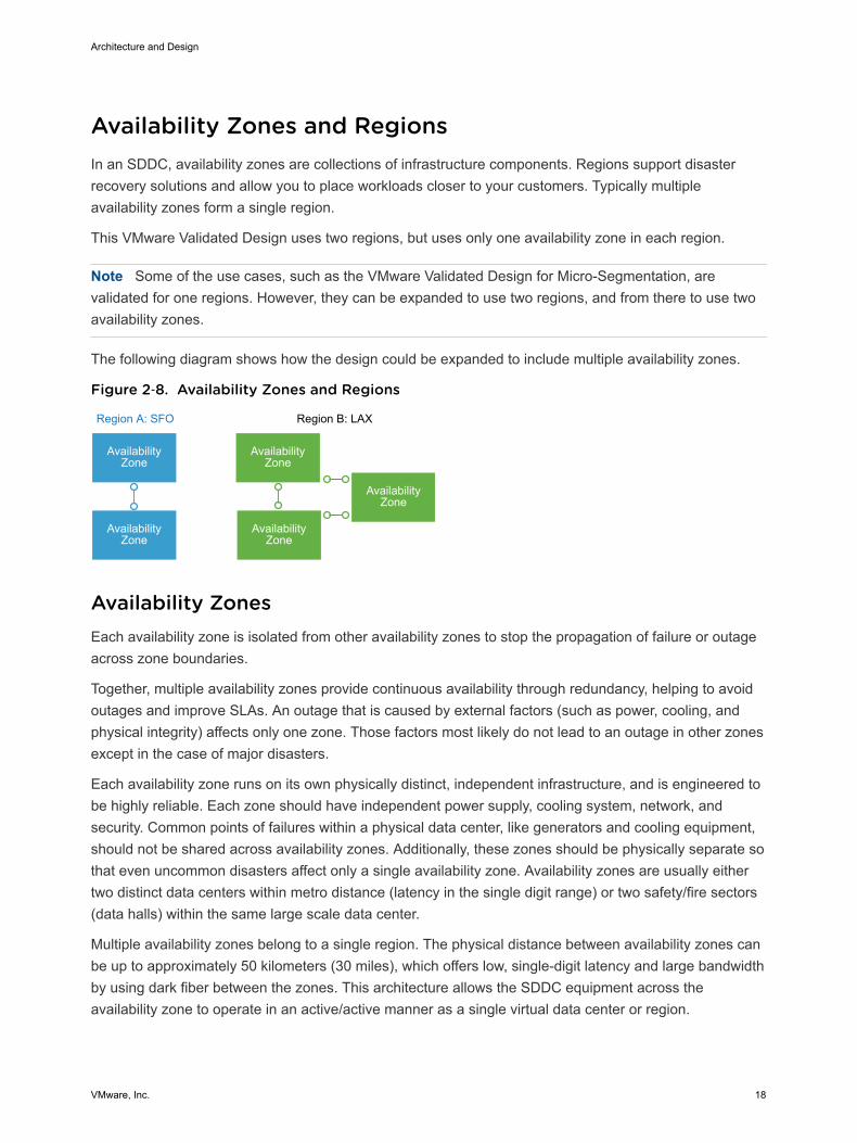
Availability Zones and RegionsIn an SDDC, availability zones are collections of infrastructure components. Regions support disasterrecovery solutions and allow you to place workloads closer to your customers. Typically multipleavailability zones form a single region.
This VMware Validated Design uses two regions, but uses only one availability zone in each region.
Note Some of the use cases, such as the VMware Validated Design for Micro-Segmentation, arevalidated for one regions. However, they can be expanded to use two regions, and from there to use twoavailability zones.
The following diagram shows how the design could be expanded to include multiple availability zones.
Figure 2‑8. Availability Zones and Regions
Region A: SFO Region B: LAX
AvailabilityZone
AvailabilityZone
AvailabilityZone
AvailabilityZone
AvailabilityZone
Availability ZonesEach availability zone is isolated from other availability zones to stop the propagation of failure or outageacross zone boundaries.
Together, multiple availability zones provide continuous availability through redundancy, helping to avoidoutages and improve SLAs. An outage that is caused by external factors (such as power, cooling, andphysical integrity) affects only one zone. Those factors most likely do not lead to an outage in other zonesexcept in the case of major disasters.
Each availability zone runs on its own physically distinct, independent infrastructure, and is engineered tobe highly reliable. Each zone should have independent power supply, cooling system, network, andsecurity. Common points of failures within a physical data center, like generators and cooling equipment,should not be shared across availability zones. Additionally, these zones should be physically separate sothat even uncommon disasters affect only a single availability zone. Availability zones are usually eithertwo distinct data centers within metro distance (latency in the single digit range) or two safety/fire sectors(data halls) within the same large scale data center.
Multiple availability zones belong to a single region. The physical distance between availability zones canbe up to approximately 50 kilometers (30 miles), which offers low, single-digit latency and large bandwidthby using dark fiber between the zones. This architecture allows the SDDC equipment across theavailability zone to operate in an active/active manner as a single virtual data center or region.
Architecture and Design
VMware, Inc. 18
You can operate workloads across multiple availability zones within the same region as if they were partof a single virtual data center. This supports an architecture with very high availability that is suitable formission critical applications. When the distance between two locations of equipment becomes too large,these locations can no longer function as two availability zones within the same region, and must betreated as separate regions.
RegionsMultiple regions support placing workloads closer to your customers, for example, by operating oneregion on the US east coast and one region on the US west coast, or operating a region in Europe andanother region in the US.
Regions are helpful in several ways.
n Regions can support disaster recovery solutions: One region can be the primary site and anotherregion can be the recovery site.
n You can use multiple regions to address data privacy laws and restrictions in certain countries bykeeping tenant data within a region in the same country.
The distance between regions can be rather large. This design uses two example regions, one region isSan Francisco (SFO), the other region is Los Angeles (LAX).
Architecture and Design
VMware, Inc. 19
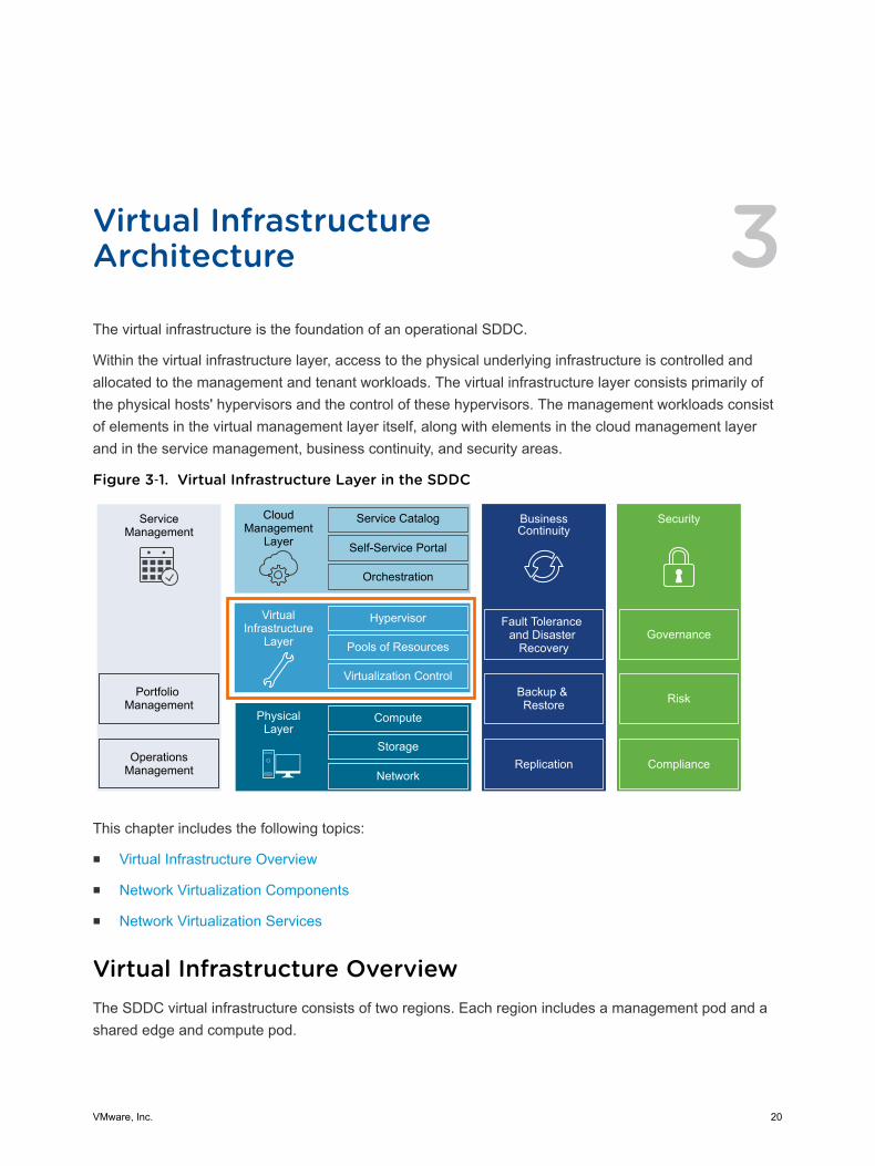
Virtual InfrastructureArchitecture 3The virtual infrastructure is the foundation of an operational SDDC.
Within the virtual infrastructure layer, access to the physical underlying infrastructure is controlled andallocated to the management and tenant workloads. The virtual infrastructure layer consists primarily ofthe physical hosts' hypervisors and the control of these hypervisors. The management workloads consistof elements in the virtual management layer itself, along with elements in the cloud management layerand in the service management, business continuity, and security areas.
Figure 3‑1. Virtual Infrastructure Layer in the SDDC
ServiceManagement
Portfolio Management
OperationsManagement
CloudManagement
Layer
Service Catalog
Self-Service Portal
Orchestration
BusinessContinuity
Fault Tolerance and Disaster
Recovery
Backup & Restore
Hypervisor
Pools of Resources
Virtualization Control
VirtualInfrastructure
Layer
Compute
Storage
Network
PhysicalLayer
Security
Replication Compliance
Risk
Governance
This chapter includes the following topics:
n Virtual Infrastructure Overview
n Network Virtualization Components
n Network Virtualization Services
Virtual Infrastructure OverviewThe SDDC virtual infrastructure consists of two regions. Each region includes a management pod and ashared edge and compute pod.
VMware, Inc. 20

Figure 3‑2. SDDC Logical Design
APP
OSAPP
OS
APP
OSAPP
OS
APP
OSAPP
OS
APP
OSAPP
OS
APP
OS
APP
OS
APP
OSAPP
OS
ESXi ESXi
APP
OSAPP
OS
APP
OSAPP
OS
Virtual InfrastructureManagement
NSXController
(Mgmt)
OtherManagementApplications
NSXEdge
(Mgmt)
NSXManager(Mgmt)
NSXManager
(Compute)
NSXEdge
(Compute)
NSXController(Compute)
ESXi ESXi ESXi ESXi ESXi ESXi
SDDCPayload
Virtual Infrastructure Compute Edge
NSX Transport Zone (Compute)
vDS (Compute) vDS (Mgmt)
NSX Transport Zone (Mgmt)
Shared Edge and Compute Cluster
Management Cluster
Managed by: Compute vCenter Server
Managed by: Management vCenter Server
Network: External(Internet/MPLS)
Network: Internal SDDCFabric (Spine/Leaf)
Management and Shared Edge and Compute Pod
vCenterServer(Mgmt)
vCenterServer
(Compute)
Management PodManagement pods run the virtual machines that manage the SDDC. These virtual machines host vCenterServer, vSphere Update Manager, NSX Manager, NSX Controller, vRealize Log Insight, and othershared management components. All management, monitoring, and infrastructure services areprovisioned to a vSphere cluster which provides high availability for these critical services. Permissionson the management cluster limit access to only administrators. This limitation protects the virtualmachines that are running the management, monitoring, and infrastructure services.
Architecture and Design
VMware, Inc. 21
Shared Edge and Compute PodThe shared edge and compute pod runs the required NSX services to enable north-south routingbetween the SDDC and the external network and east-west routing inside the SDDC. This pod also hoststhe SDDC tenant virtual machines (sometimes referred to as workloads or payloads). As the SDDC growsadditional compute-only pods can be added to support a mix of different types of workloads for differenttypes of SLAs.
Network Virtualization ComponentsVMware NSX for vSphere, the network virtualization platform, is a key solution in the SDDC architecture.The NSX for vSphere platform consists of several components that are relevant to the networkvirtualization design.
NSX for vSphere PlatformNSX for vSphere creates a network virtualization layer. All virtual networks are created on top of this layer,which is an abstraction between the physical and virtual networks. Several components are required tocreate this network virtualization layer:
n vCenter Server
n NSX Manager
n NSX Controller
n NSX Virtual Switch
Architecture and Design
VMware, Inc. 22
These components are separated into different planes to create communications boundaries and provideisolation of workload data from system control messages.
Data plane Workload data is contained wholly within the data plane. NSX logicalswitches segregate unrelated workload data. The data is carried overdesignated transport networks in the physical network. The NSX VirtualSwitch, distributed routing, and the distributed firewall are also implementedin the data plane.
Control plane Network virtualization control messages are located in the control plane.Control plane communication should be carried on secure physicalnetworks (VLANs) that are isolated from the transport networks that areused for the data plane. Control messages are used to set up networkingattributes on NSX Virtual Switch instances, as well as to configure andmanage disaster recovery and distributed firewall components on eachESXi host.
Management plane The network virtualization orchestration happens in the management plane.In this layer, cloud management platforms such as VMware vRealize®
Automation™ can request, consume, and destroy networking resources forvirtual workloads. Communication is directed from the cloud managementplatform to vCenter Server to create and manage virtual machines, and toNSX Manager to consume networking resources.
Network Virtualization ServicesNetwork virtualization services include logical switches, logical routers, logical firewalls, and othercomponents of NSX for vSphere.
Logical SwitchesNSX for vSphere logical switches create logically abstracted segments to which tenant virtual machinescan connect. A single logical switch is mapped to a unique VXLAN segment ID and is distributed acrossthe ESXi hypervisors within a transport zone. This allows line-rate switching in the hypervisor withoutcreating constraints of VLAN sprawl or spanning tree issues.
Universal Distributed Logical RouterThe NSX for vSphere Universal Distributed Logical Router is optimized for forwarding in the virtualizedspace (between VMs, on VXLAN- or VLAN-backed port groups). Features include:
n High performance, low overhead first hop routing.
n Scaling the number of hosts.
n Support for up to 1,000 logical interfaces (LIFs) on each distributed logical router.
Architecture and Design
VMware, Inc. 23
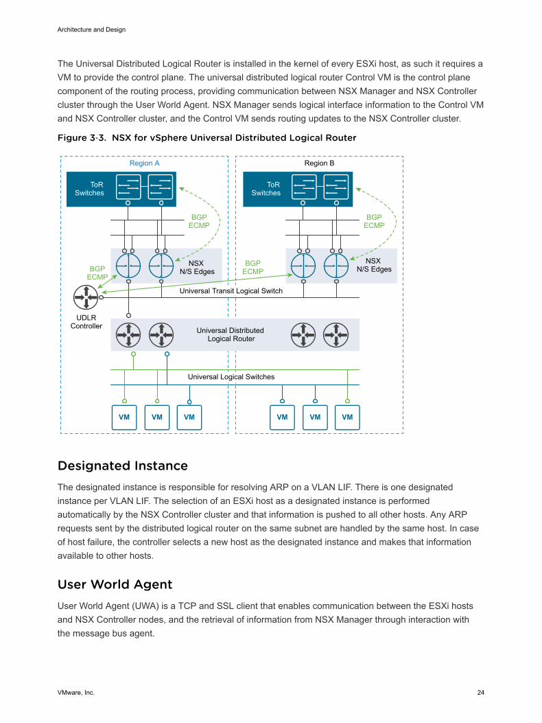
The Universal Distributed Logical Router is installed in the kernel of every ESXi host, as such it requires aVM to provide the control plane. The universal distributed logical router Control VM is the control planecomponent of the routing process, providing communication between NSX Manager and NSX Controllercluster through the User World Agent. NSX Manager sends logical interface information to the Control VMand NSX Controller cluster, and the Control VM sends routing updates to the NSX Controller cluster.
Figure 3‑3. NSX for vSphere Universal Distributed Logical Router
Region A
Universal Transit Logical Switch
Universal Distributed Logical Router
Universal Logical Switches
NSX N/S Edges
UDLRController
BGPECMP
BGPECMPBGP
ECMP
NSX N/S Edges
BGPECMP
Region B
ToRSwitches
ToRSwitches
Designated InstanceThe designated instance is responsible for resolving ARP on a VLAN LIF. There is one designatedinstance per VLAN LIF. The selection of an ESXi host as a designated instance is performedautomatically by the NSX Controller cluster and that information is pushed to all other hosts. Any ARPrequests sent by the distributed logical router on the same subnet are handled by the same host. In caseof host failure, the controller selects a new host as the designated instance and makes that informationavailable to other hosts.
User World AgentUser World Agent (UWA) is a TCP and SSL client that enables communication between the ESXi hostsand NSX Controller nodes, and the retrieval of information from NSX Manager through interaction withthe message bus agent.
Architecture and Design
VMware, Inc. 24
Edge Services GatewayWhile the Universal Logical Router provides VM to VM or east-west routing, the NSX Edge servicesgateway provides north-south connectivity, by peering with upstream Top of Rack switches, therebyenabling tenants to access public networks.
Logical FirewallNSX for vSphere Logical Firewall provides security mechanisms for dynamic virtual data centers.
n The Distributed Firewall allows you to segment virtual data center entities like virtual machines.Segmentation can be based on VM names and attributes, user identity, vCenter objects like datacenters, and hosts, or can be based on traditional networking attributes like IP addresses, portgroups, and so on.
n The Edge Firewall component helps you meet key perimeter security requirements, such as buildingDMZs based on IP/VLAN constructs, tenant-to-tenant isolation in multi-tenant virtual data centers,Network Address Translation (NAT), partner (extranet) VPNs, and user-based SSL VPNs.
The Flow Monitoring feature displays network activity between virtual machines at the application protocollevel. You can use this information to audit network traffic, define and refine firewall policies, and identifythreats to your network.
Logical Virtual Private Networks (VPNs)SSL VPN-Plus allows remote users to access private corporate applications. IPSec VPN offers site-to-siteconnectivity between an NSX Edge instance and remote sites. L2 VPN allows you to extend yourdatacenter by allowing virtual machines to retain network connectivity across geographical boundaries.
Logical Load BalancerThe NSX Edge load balancer enables network traffic to follow multiple paths to a specific destination. Itdistributes incoming service requests evenly among multiple servers in such a way that the loaddistribution is transparent to users. Load balancing thus helps in achieving optimal resource utilization,maximizing throughput, minimizing response time, and avoiding overload. NSX Edge provides loadbalancing up to Layer 7.
Service ComposerService Composer helps you provision and assign network and security services to applications in avirtual infrastructure. You map these services to a security group, and the services are applied to thevirtual machines in the security group.
Data Security provides visibility into sensitive data that are stored within your organization's virtualizedand cloud environments. Based on the violations that are reported by the NSX for vSphere Data Securitycomponent, NSX security or enterprise administrators can ensure that sensitive data is adequatelyprotected and assess compliance with regulations around the world.
Architecture and Design
VMware, Inc. 25
NSX for vSphere ExtensibilityVMware partners integrate their solutions with the NSX for vSphere platform to enable an integratedexperience across the entire SDDC. Data center operators can provision complex, multi-tier virtualnetworks in seconds, independent of the underlying network topology or components.
Architecture and Design
VMware, Inc. 26
Operations ArchitectureOverview 4The architecture of the operations management layer includes management components that providesupport for the main types of operations in an SDDC. For the micro-segmentation use case, you canperform monitoring, logging with vRealize Log Insight.
Within the operations layer, the underlying physical infrastructure and the virtual management and tenantworkloads are monitored in real-time. Information is collected in the form of structured data (metrics) andunstructured data (logs). The operations layer also knows about the SDDC topology, that is physical andvirtual compute, networking, and storage resources, which are key in intelligent and dynamic operationalmanagement. The operations layer consists primarily of monitoring, logging, backup and restore, disasterrecovery and security compliance adherence. Together, these components ensure that servicemanagement, business continuity, and security areas are met.
Logging ArchitecturevRealize Log Insight provides real-time log management and log analysis with machine learning-basedintelligent grouping, high-performance searching, and troubleshooting across physical, virtual, and cloudenvironments.
OverviewvRealize Log Insight collects data from ESXi hosts using the syslog protocol. It connects to other VMwareproducts, like vCenter Server, to collect events, tasks, and alarm data. vRealize Log Insight also functionsas a collection and analysis point for any system that is capable of sending syslog data.
To collect additional logs, you can install an ingestion agent on Linux or Windows servers, or you can usethe preinstalled agent on certain VMware products. Using preinstalled agents is useful for customapplication logs and operating systems that do not natively support the syslog protocol, such as Windows.
Deployment ModelsYou can deploy vRealize Log Insight as a virtual appliance in one of the following configurations:
n Standalone node
VMware, Inc. 27
n Cluster of one master and at least two worker nodes. You can establish high availability by using theintegrated load balancer (ILB).
The compute and storage resources of the vRealize Log Insight instances can scale-up as growthdemands.
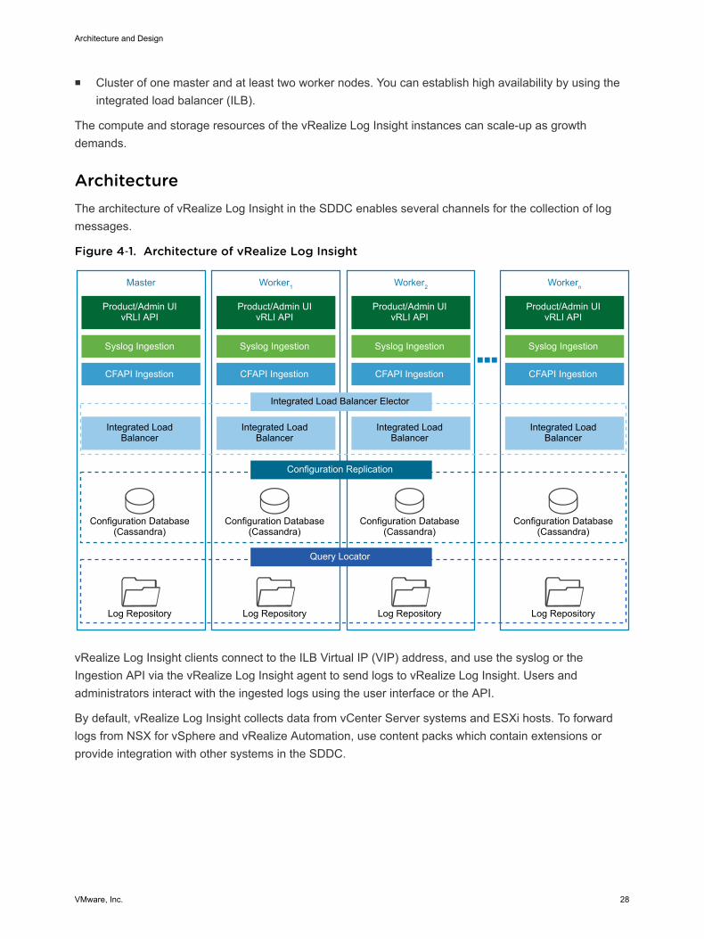
ArchitectureThe architecture of vRealize Log Insight in the SDDC enables several channels for the collection of logmessages.
Figure 4‑1. Architecture of vRealize Log Insight
Master
Product/Admin UIvRLI API
Integrated Load Balancer
Configuration Database(Cassandra)
Log Repository
Integrated Load Balancer Elector
Configuration Replication
Query Locator
Syslog Ingestion
CFAPI Ingestion
Worker1
Product/Admin UIvRLI API
Integrated Load Balancer
Configuration Database(Cassandra)
Log Repository
Syslog Ingestion
CFAPI Ingestion
Worker2
Product/Admin UIvRLI API
Integrated Load Balancer
Configuration Database(Cassandra)
Log Repository
Syslog Ingestion
CFAPI Ingestion
Workern
Product/Admin UIvRLI API
Integrated Load Balancer
Configuration Database(Cassandra)
Log Repository
Syslog Ingestion
CFAPI Ingestion
vRealize Log Insight clients connect to the ILB Virtual IP (VIP) address, and use the syslog or theIngestion API via the vRealize Log Insight agent to send logs to vRealize Log Insight. Users andadministrators interact with the ingested logs using the user interface or the API.
By default, vRealize Log Insight collects data from vCenter Server systems and ESXi hosts. To forwardlogs from NSX for vSphere and vRealize Automation, use content packs which contain extensions orprovide integration with other systems in the SDDC.
Architecture and Design
VMware, Inc. 28
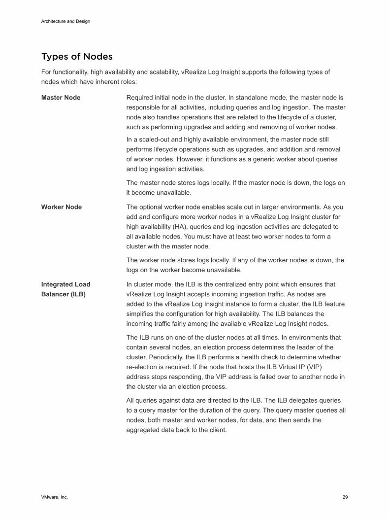
Types of NodesFor functionality, high availability and scalability, vRealize Log Insight supports the following types ofnodes which have inherent roles:
Master Node Required initial node in the cluster. In standalone mode, the master node isresponsible for all activities, including queries and log ingestion. The masternode also handles operations that are related to the lifecycle of a cluster,such as performing upgrades and adding and removing of worker nodes.
In a scaled-out and highly available environment, the master node stillperforms lifecycle operations such as upgrades, and addition and removalof worker nodes. However, it functions as a generic worker about queriesand log ingestion activities.
The master node stores logs locally. If the master node is down, the logs onit become unavailable.
Worker Node The optional worker node enables scale out in larger environments. As youadd and configure more worker nodes in a vRealize Log Insight cluster forhigh availability (HA), queries and log ingestion activities are delegated toall available nodes. You must have at least two worker nodes to form acluster with the master node.
The worker node stores logs locally. If any of the worker nodes is down, thelogs on the worker become unavailable.
Integrated LoadBalancer (ILB)
In cluster mode, the ILB is the centralized entry point which ensures thatvRealize Log Insight accepts incoming ingestion traffic. As nodes areadded to the vRealize Log Insight instance to form a cluster, the ILB featuresimplifies the configuration for high availability. The ILB balances theincoming traffic fairly among the available vRealize Log Insight nodes.
The ILB runs on one of the cluster nodes at all times. In environments thatcontain several nodes, an election process determines the leader of thecluster. Periodically, the ILB performs a health check to determine whetherre-election is required. If the node that hosts the ILB Virtual IP (VIP)address stops responding, the VIP address is failed over to another node inthe cluster via an election process.
All queries against data are directed to the ILB. The ILB delegates queriesto a query master for the duration of the query. The query master queries allnodes, both master and worker nodes, for data, and then sends theaggregated data back to the client.
Architecture and Design
VMware, Inc. 29
Use the ILB Web interface for administrative activities unless you areperforming administrative activities on individual nodes. The presents datafrom the master and from the worker nodes in a scaled-out cluster in aunified display (single pane of glass).
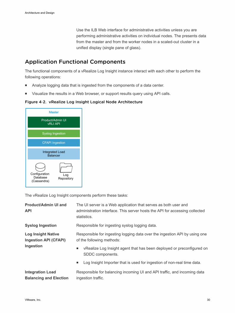
Application Functional ComponentsThe functional components of a vRealize Log Insight instance interact with each other to perform thefollowing operations:
n Analyze logging data that is ingested from the components of a data center.
n Visualize the results in a Web browser, or support results query using API calls.
Figure 4‑2. vRealize Log Insight Logical Node Architecture
Master
Product/Admin UIvRLI API
Integrated Load Balancer
Configuration Database
(Cassandra)
LogRepository
Syslog Ingestion
CFAPI Ingestion
The vRealize Log Insight components perform these tasks:
Product/Admin UI andAPI
The UI server is a Web application that serves as both user andadministration interface. This server hosts the API for accessing collectedstatistics.
Syslog Ingestion Responsible for ingesting syslog logging data.
Log Insight NativeIngestion API (CFAPI)Ingestion
Responsible for ingesting logging data over the ingestion API by using oneof the following methods:
n vRealize Log Insight agent that has been deployed or preconfigured onSDDC components.
n Log Insight Importer that is used for ingestion of non-real time data.
Integration LoadBalancing and Election
Responsible for balancing incoming UI and API traffic, and incoming dataingestion traffic.
Architecture and Design
VMware, Inc. 30
The Integrated Load Balancer is a Linux Virtual Server (LVS) that is built inthe Linux Kernel for Layer 4 load balancing . Each node in vRealize LogInsight contains a service running the Integrated Load Balancer, but only asingle node functions as the leader at all times. In a single-node vRealizeLog Insight instance, this is always the master node. In a scaled-outvRealize Log Insight cluster, this role can be inherited by any of theavailable nodes during the election process. The leader periodicallyperforms health checks to determine whether a reelection process isrequired for the cluster.
Configuration Database Stores configuration information about the vRealize Log Insight nodes andcluster. The information that is stored in the database is periodicallyreplicated to all available vRealize Log Insight nodes.
Log Repository Stores logging data that is ingested in vRealize Log Insight. The loggingrepository is local to each node and not replicated. If a node is offline orremoved, the logging data which is stored on that node becomesinaccessible. In environments where an ILB is configured, incoming loggingdata is evenly distributed across all available nodes.
When a query arrives from the ILB, the vRealize Log Insight node that isholding the ILB leader role delegates the query to any of the availablenodes in the cluster.
Authentication ModelsYou can configure vRealize Log Insight user authentication to utilize one or more of the followingauthentication models:
n Microsoft Active Directory
n Local Accounts
n VMware Identity Manager
Content PacksContent packs help extend Log Insight with valuable troubleshooting information by providing structureand meaning to raw logging data that is collected from either a vRealize Log Insight agent, vRealize LogInsight Importeror a syslog stream. They add vRealize Log Insight agent configurations, providing out-of-the-box parsing capabilities for a standard logging directories and logging formats, along withdashboards, extracted fields, alert definitions, query lists, and saved queries from the logging data relatedto a specific product in vRealize Log Insight. You can learn more details about and download contentpacks from the Log Insight Content Pack Marketplace or the VMware Solutions Exchange.
Architecture and Design
VMware, Inc. 31
ArchivingvRealize Log Insight supports data archiving on an NFS shared storage that the vRealize Log Insightnodes can access. However, vRealize Log Insight does not manage the NFS mount that is used forarchiving purposes. vRealize Log Insight also does not perform cleanup of the archival files.
The NFS mount for archiving can run out of free space or become unavailable for a period of time greaterthan the retention period of the virtual appliance. In that case, vRealize Log Insight stops ingesting newdata until the NFS mount has enough free space or becomes available, or until archiving is disabled. Ifarchiving is enabled, system notifications from vRealize Log Insight sends you an email when the NFSmount is about to run out of space or is unavailable.
BackupYou back up each vRealize Log Insight cluster using traditional virtual machine backup solutions. Thesesolutions, for example as vSphere Data Protection, are compatible with vSphere Storage APIs for DataProtection (VADP).
Multi-Region vRealize Log Insight DeploymentThe scope of this validated design can cover multiple regions. In a multi-region implementation, vRealizeLog Insight provides a logging infrastructure in all regions of the SDDC. Using vRealize Log Insightacross multiple regions requires deploying a cluster in each region. vRealize Log Insight supports eventforwarding to other vRealize Log Insight deployments across regions in the SDDC. Implementing failoverby using vSphere Replication or disaster recovery by using Site Recovery Manager is not necessary. Theevent forwarding feature adds tags to log message that identify the source region. Event filtering preventslooping messages between the regions.
Architecture and Design
VMware, Inc. 32
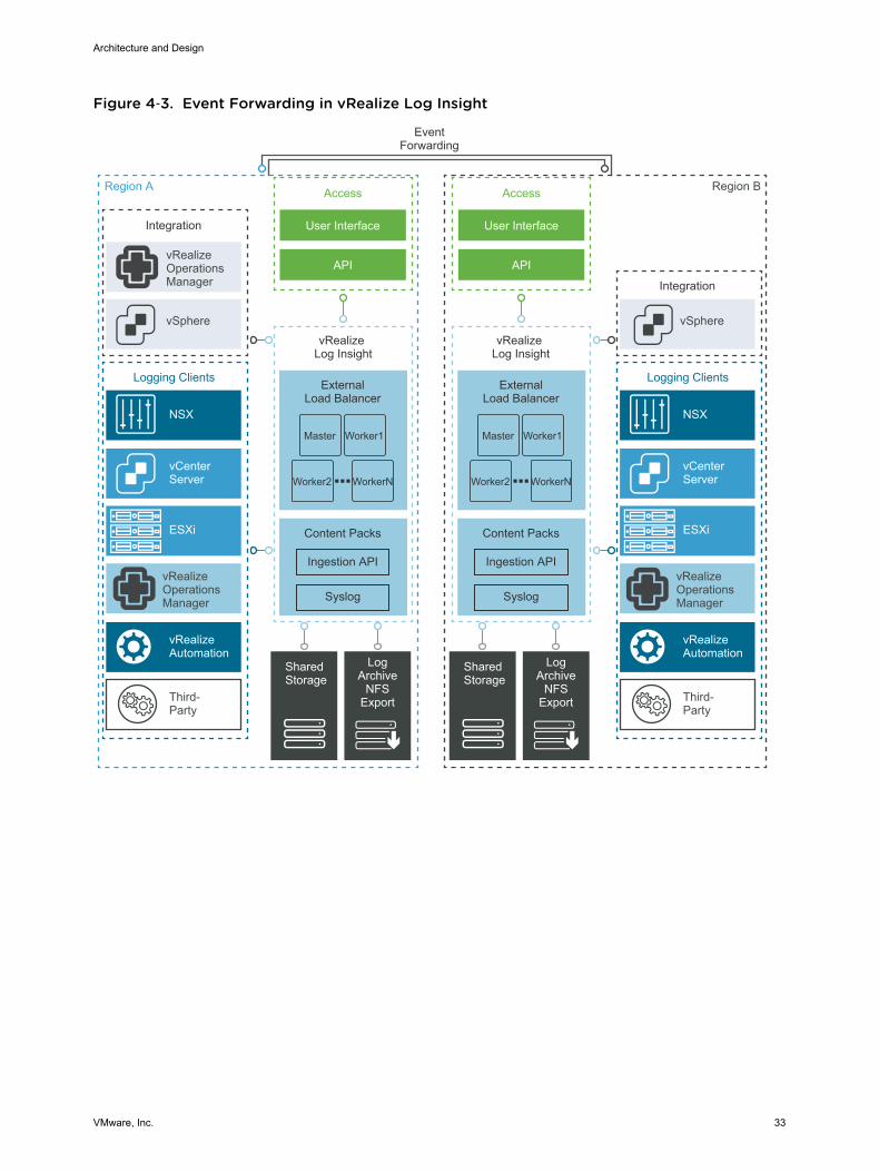
Figure 4‑3. Event Forwarding in vRealize Log Insight
Region A
EventForwarding
Integration
ExternalLoad Balancer
vSphere
Access
User Interface
APIvRealizeOperationsManager
vRealizeOperationsManager
Logging Clients
vCenter Server
ESXi
NSX
vRealizeAutomation
Third-Party
Content Packs
Syslog
Ingestion API
ExternalLoad Balancer
Content Packs
Syslog
Ingestion API
Shared Storage
LogArchive
NFSExport
Region B
vRealize Log Insight
vRealize Log Insight
Integration
vSphere
Access
User Interface
API
vRealizeOperationsManager
Logging Clients
vCenter Server
ESXi
NSX
vRealizeAutomation
Third-Party
Shared Storage
LogArchive
NFSExport
Master Worker1
Worker2 WorkerN
Master Worker1
Worker2 WorkerN
Architecture and Design
VMware, Inc. 33
Detailed Design 5The Software-Defined Data Center (SDDC) detailed design considers both physical and virtualinfrastructure design. It includes numbered design decisions and the justification and implications of eachdecision.
Each section also includes detailed discussion and diagrams.
Physical InfrastructureDesign
Focuses on the three main pillars of any data center, compute, storage andnetwork. In this section you find information about availability zones andregions. The section also provides details on the rack and podconfiguration, and on physical hosts and the associated storage andnetwork configurations.
Virtual InfrastructureDesign
Provides details on the core virtualization software configuration. Thissection has information on the ESXi hypervisor, vCenter Server, the virtualnetwork design including VMware NSX, and on software-defined storagefor VMware vSAN. This section also includes details on business continuity(backup and restore) and on disaster recovery.
OperationsInfrastructure Design
Explains how to architect, install, and configure vRealize Log Insight. Youlearn how to ensure that service management within the SDDC iscomprehensive.
VMware, Inc. 34
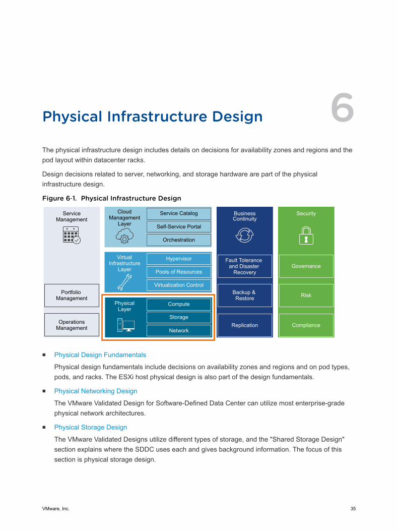
Physical Infrastructure Design 6The physical infrastructure design includes details on decisions for availability zones and regions and thepod layout within datacenter racks.
Design decisions related to server, networking, and storage hardware are part of the physicalinfrastructure design.
Figure 6‑1. Physical Infrastructure Design
ServiceManagement
Portfolio Management
OperationsManagement
CloudManagement
Layer
Service Catalog
Self-Service Portal
Orchestration
BusinessContinuity
Fault Tolerance and Disaster
Recovery
Backup & Restore
Hypervisor
Pools of Resources
Virtualization Control
VirtualInfrastructure
Layer
Compute
Storage
Network
PhysicalLayer
Security
Replication Compliance
Risk
Governance
n Physical Design Fundamentals
Physical design fundamentals include decisions on availability zones and regions and on pod types,pods, and racks. The ESXi host physical design is also part of the design fundamentals.
n Physical Networking Design
The VMware Validated Design for Software-Defined Data Center can utilize most enterprise-gradephysical network architectures.
n Physical Storage Design
The VMware Validated Designs utilize different types of storage, and the "Shared Storage Design"section explains where the SDDC uses each and gives background information. The focus of thissection is physical storage design.
VMware, Inc. 35
Physical Design FundamentalsPhysical design fundamentals include decisions on availability zones and regions and on pod types,pods, and racks. The ESXi host physical design is also part of the design fundamentals.
Availability Zones and RegionsAvailability zones and regions are used for different purposes.
Availability zones An availability zone is the fault domain of the SDDC. Multiple availabilityzone scan provide continuous availability of an SDDC, minimizeunavailability of services and improve SLAs.
Regions Regions provide disaster recovery across different SDDC instances. Thisdesign uses two regions. Each region is a separate SDDC instance. Theregions have a similar physical layer design and virtual infrastructuredesign but different naming. If you are expanding your design to includetwo regions, see the Business Continuity / Disaster Recovery Designchapter in the VMware Validated Design for the Software-Defined DataCenter Reference Architecture document.
Note This design leverages a single availability zone for a one region deployment, and a singleavailability zone in each region in the case of a two region deployment.
The two-region design uses the following regions. The region identifier uses United Nations Code forTrade and Transport Locations(UN/LOCODE) along with a numeric instance ID.
Region Region Identifier Region-specific Domain Name Region Description
A SFO01 sfo01.rainpole.local San Francisco, CA, USA based data center
B LAX01 lax01.rainpole.local Los Angeles, CA, USA based data center
Note Region Identifiers vary based on the locations used in your deployment.
Table 6‑1. Availability Zones and Regions Design Decisions
Decision ID Design Decision Design Justification Design Implication
SDDC-PHY-001 Per region, a single availabilityzone that can support all SDDCmanagement components isdeployed.
A single availability zone can support allSDDC management and computecomponents for a region. You can lateradd another availability zone to extendand scale the management and computecapabilities of the SDDC.
Results in limited redundancy ofthe overall solution. The singleavailability zone can become asingle point of failure and preventhigh-availability design solutions.
SDDC-PHY-002 Use a single region for the initialdeployment. Expand the designto two regions if appropriate.
Supports the technical requirement ofmulti-region failover capability asoutlined in the design objectives.
Having multiple regions requiresan increased solution footprintand associated costs.
Architecture and Design
VMware, Inc. 36
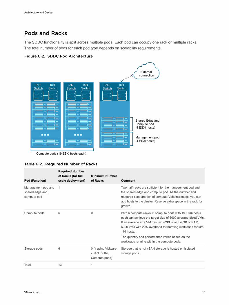
Pods and RacksThe SDDC functionality is split across multiple pods. Each pod can occupy one rack or multiple racks.The total number of pods for each pod type depends on scalability requirements.
Figure 6‑2. SDDC Pod Architecture
ToR Switch
ToR Switch
ToR Switch
ToR Switch
Compute pods (19 ESXi hosts each)
Shared Edge andCompute pod(4 ESXi hosts)
Management pod(4 ESXi hosts)
External connection
ToR Switch
ToR Switch
Table 6‑2. Required Number of Racks
Pod (Function)
Required Numberof Racks (for fullscale deployment)
Minimum Numberof Racks Comment
Management pod andshared edge andcompute pod
1 1 Two half-racks are sufficient for the management pod andthe shared edge and compute pod. As the number andresource consumption of compute VMs increases, you canadd hosts to the cluster. Reserve extra space in the rack forgrowth.
Compute pods 6 0 With 6 compute racks, 6 compute pods with 19 ESXi hostseach can achieve the target size of 6000 average-sized VMs.If an average size VM has two vCPUs with 4 GB of RAM,6000 VMs with 20% overhead for bursting workloads require114 hosts.
The quantity and performance varies based on theworkloads running within the compute pods.
Storage pods 6 0 (if using VMwarevSAN for theCompute pods)
Storage that is not vSAN storage is hosted on isolatedstorage pods.
Total 13 1
Architecture and Design
VMware, Inc. 37
Table 6‑3. POD and Racks Design Decisions
Decision ID Design Decision Design Justification Design Implication
SDDC-PHY-003
The management podand the shared edgeand compute podoccupy the same rack.
The number of required compute resources for themanagement pod (4 ESXi hosts) and shared edgeand compute pod (4 ESXi hosts) are low. Adedicated rack for each pod is not necessary.
On-ramp and off-ramp connectivity to physicalnetworks can be supplied to both the managementand compute pods. For example, north-south L3routing on NSX Edge virtual appliances becomesavailable
Edge resources require external connectivity tophysical network devices. Placing edge resourcesfor management and compute in the same rackminimizes VLAN spread.
The design must include sufficientpower and cooling to operate theserver equipment. Requirementsdepend on the selected vendorand products.
If the equipment of an entire rackfails, the cause, such as floodingor an earthquake, also affectsneighboring racks. A secondregion must be available tomitigate downtime.
SDDC-PHY-004
Storage pods canoccupy one or moreracks.
To simplify scale-out of the SDDC infrastructure,the relationship from the storage pod to rack isstandardized.
It is possible that the storage system arrives fromthe manufacturer in a dedicated rack or set of racksand a storage system. The design accommodatesthis type of system.
The design must include sufficientpower and cooling to operate thestorage equipment. Requirementsdepend on the selected vendorand products.
SDDC-PHY-005
Each rack has twoseparate power feeds.
Redundant power feeds increase availability byensuring that failure of a power feed does not bringdown all equipment in a rack.
Combined with redundant network connections intoa rack and within a rack, redundant power feedsprevent equipment failure in an entire rack.
All equipment used must supporttwo separate power feeds. Theequipment must keep running ifone power feed fails.
If the equipment of an entire rackfails, the cause, such as floodingor an earthquake, also affectsneighboring racks. A secondregion must be available tomitigate downtime.
SDDC-PHY-006
Mount the computeresources (minimum of 4ESXi hosts) for themanagement podtogether in a rack.
Mounting the compute resources for themanagement pod together can ease physical datacenter design, deployment, and troubleshooting.
None.
SDDC-PHY-007
Mount the computeresources for the sharededge and compute pod(minimum of 4 ESXiservers) together in arack.
Mounting the compute resources for the sharededge and compute pod together can ease physicaldata center design, deployment, andtroubleshooting.
None.
ESXi Host Physical Design SpecificationsThe physical design specifications of the ESXi host list the characteristics of the hosts that were usedduring deployment and testing of this VMware Validated Design.
Architecture and Design
VMware, Inc. 38
Physical Design Specification FundamentalsThe configuration and assembly process for each system is standardized, with all components installedthe same manner on each host. Standardizing the entire physical configuration of the ESXi hosts iscritical to providing an easily manageable and supportable infrastructure because standardizationeliminates variability. Consistent PCI card slot location, especially for network controllers, is essential foraccurate alignment of physical to virtual I/O resources. Deploy ESXi hosts with identical configuration,including identical storage, and networking configurations, across all cluster members. Identicalconfigurations ensure an even balance of virtual machine storage components across storage andcompute resources.
Select all ESXi host hardware, including CPUs following the VMware Compatibility Guide.
The sizing of the physical servers for the ESXi hosts for the management and edge pods has specialconsideration because it is based on the VMware document VMware Virtual SAN Ready Nodes, as thesepod type use VMware vSAN.
n An average sized VM has two vCPUs with 4 GB of RAM.
n A standard 2U server can host 60 average-sized VMs on a single ESXi host.
Table 6‑4. ESXi Host Design Decisions
Decision ID Design Decision Design Justification Design Implication
SDDC-PHY-008 Use vSAN Ready Nodes. Using a vSAN Ready Node ensuresseamless compatibility with vSAN duringthe deployment.
Might limit hardware choices.
SDDC-PHY-009 All nodes must have uniformconfigurations across agiven cluster.
A balanced cluster delivers morepredictable performance even duringhardware failures. In addition, performanceimpact during resync/rebuild is minimalwhen the cluster is balanced.
Vendor sourcing, budgeting andprocurement considerations foruniform server nodes will beapplied on a per cluster basis.
ESXi Host MemoryThe amount of memory required for compute pods will vary depending on the workloads running in thepod. When sizing memory for compute pod hosts it is important to remember the admission controlsetting (n+1) which reserves one host resource for failover or maintenance.
Note See the VMware vSAN 6.5 Design and Sizing Guide for more information about disk groups,including design and sizing guidance. The number of disk groups and disks that an ESXi host managesdetermines memory requirements. 32 GB of RAM is required to support the maximum number of diskgroups.
Table 6‑5. Host Memory Design Decision
Decision ID Design Decision Design Justification Design Implication
SDDC-PHY-010 Set up each ESXi host in the managementpod to have a minimum 192 GB RAM.
The management and edge VMs in thispod require a total 424 GB RAM.
None.
Architecture and Design
VMware, Inc. 39
Host Boot Device Background ConsiderationsMinimum boot disk size for ESXi in SCSI-based devices (SAS/SATA/SAN) is greater than 5 GB. ESXi canbe deployed using stateful local SAN SCSI boot devices, or by using vSphere Auto Deploy.
What is supported depends on the version of vSAN that you are using:
n vSAN does not support stateless vSphere Auto Deploy
n vSAN 5.5 and greater supports USB/SD embedded devices for ESXi boot device (4 GB or greater).
n Since vSAN 6.0, there is an option to use SATADOM as a supported boot device.
See the VMware vSAN 6.5 Design and Sizing Guide to choose the option that best fits your hardware.
Physical Networking DesignThe VMware Validated Design for Software-Defined Data Center can utilize most enterprise-gradephysical network architectures.
Leaf-and-Spine and Network Virtualization ArchitectureAs virtualization, cloud computing, and distributed cloud become more pervasive in the data center, a shiftin the traditional three-tier networking model is taking place. This shift addresses simplicity and scalability.
SimplicityThe traditional core-aggregate-access model is efficient for north/south traffic that travels in and out of thedata center. This model is usually built for redundancy and resiliency against failure. However, theSpanning Tree Protocol (STP) typically blocks 50 percent of the critical network links to prevent networkloops, which means 50 percent of the maximum bandwidth is wasted until something fails.
A core-aggregate-access architecture is still widely used for service-oriented traffic that travelsnorth/south. However, the trends in traffic patterns are changing with the types of workloads. In today’sdata centers east/west or server-to-server traffic is common. If the servers in a cluster are performing aresource-intensive calculation in parallel, unpredictable latency or lack of bandwidth are undesirable.Powerful servers that perform these calculations can attempt to communicate with each other, but if theycannot communicate efficiently because of a bottleneck in the network architecture, wasted capitalexpenditure results.
One way to solve the problem is to create a leaf-and-spine architecture, also known as a distributed core.
A leaf-and-spine architecture has two main components: spine switches and leaf switches.
n Spine switches can be thought of as the core, but instead of being a large, chassis-based switchingplatform, the spine consists of many high-throughput Layer 3 switches with high port density.
n Leaf switches can be treated as the access layer. Leaf switches provide network connection points forservers and uplink to the spine switches.
Architecture and Design
VMware, Inc. 40
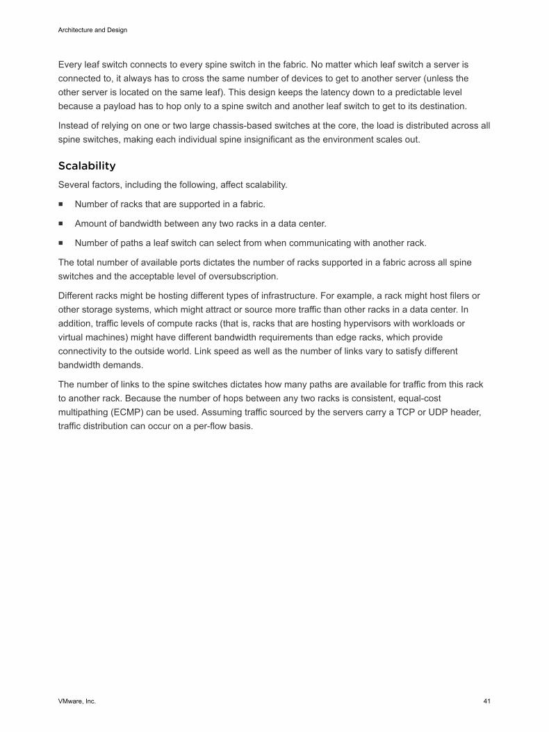
Every leaf switch connects to every spine switch in the fabric. No matter which leaf switch a server isconnected to, it always has to cross the same number of devices to get to another server (unless theother server is located on the same leaf). This design keeps the latency down to a predictable levelbecause a payload has to hop only to a spine switch and another leaf switch to get to its destination.
Instead of relying on one or two large chassis-based switches at the core, the load is distributed across allspine switches, making each individual spine insignificant as the environment scales out.
ScalabilitySeveral factors, including the following, affect scalability.
n Number of racks that are supported in a fabric.
n Amount of bandwidth between any two racks in a data center.
n Number of paths a leaf switch can select from when communicating with another rack.
The total number of available ports dictates the number of racks supported in a fabric across all spineswitches and the acceptable level of oversubscription.
Different racks might be hosting different types of infrastructure. For example, a rack might host filers orother storage systems, which might attract or source more traffic than other racks in a data center. Inaddition, traffic levels of compute racks (that is, racks that are hosting hypervisors with workloads orvirtual machines) might have different bandwidth requirements than edge racks, which provideconnectivity to the outside world. Link speed as well as the number of links vary to satisfy differentbandwidth demands.
The number of links to the spine switches dictates how many paths are available for traffic from this rackto another rack. Because the number of hops between any two racks is consistent, equal-costmultipathing (ECMP) can be used. Assuming traffic sourced by the servers carry a TCP or UDP header,traffic distribution can occur on a per-flow basis.
Architecture and Design
VMware, Inc. 41
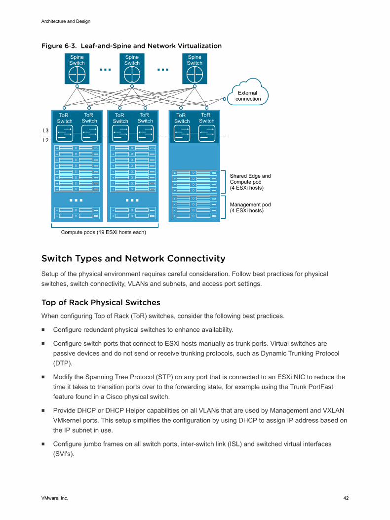
Figure 6‑3. Leaf-and-Spine and Network VirtualizationSpineSwitch
SpineSwitch
SpineSwitch
ToR Switch
ToR Switch
ToR Switch
ToR Switch
Compute pods (19 ESXi hosts each)
Shared Edge andCompute pod(4 ESXi hosts)
Management pod(4 ESXi hosts)
External connection
ToR Switch
ToR Switch
L2
L3
Switch Types and Network ConnectivitySetup of the physical environment requires careful consideration. Follow best practices for physicalswitches, switch connectivity, VLANs and subnets, and access port settings.
Top of Rack Physical SwitchesWhen configuring Top of Rack (ToR) switches, consider the following best practices.
n Configure redundant physical switches to enhance availability.
n Configure switch ports that connect to ESXi hosts manually as trunk ports. Virtual switches arepassive devices and do not send or receive trunking protocols, such as Dynamic Trunking Protocol(DTP).
n Modify the Spanning Tree Protocol (STP) on any port that is connected to an ESXi NIC to reduce thetime it takes to transition ports over to the forwarding state, for example using the Trunk PortFastfeature found in a Cisco physical switch.
n Provide DHCP or DHCP Helper capabilities on all VLANs that are used by Management and VXLANVMkernel ports. This setup simplifies the configuration by using DHCP to assign IP address based onthe IP subnet in use.
n Configure jumbo frames on all switch ports, inter-switch link (ISL) and switched virtual interfaces(SVI's).
Architecture and Design
VMware, Inc. 42
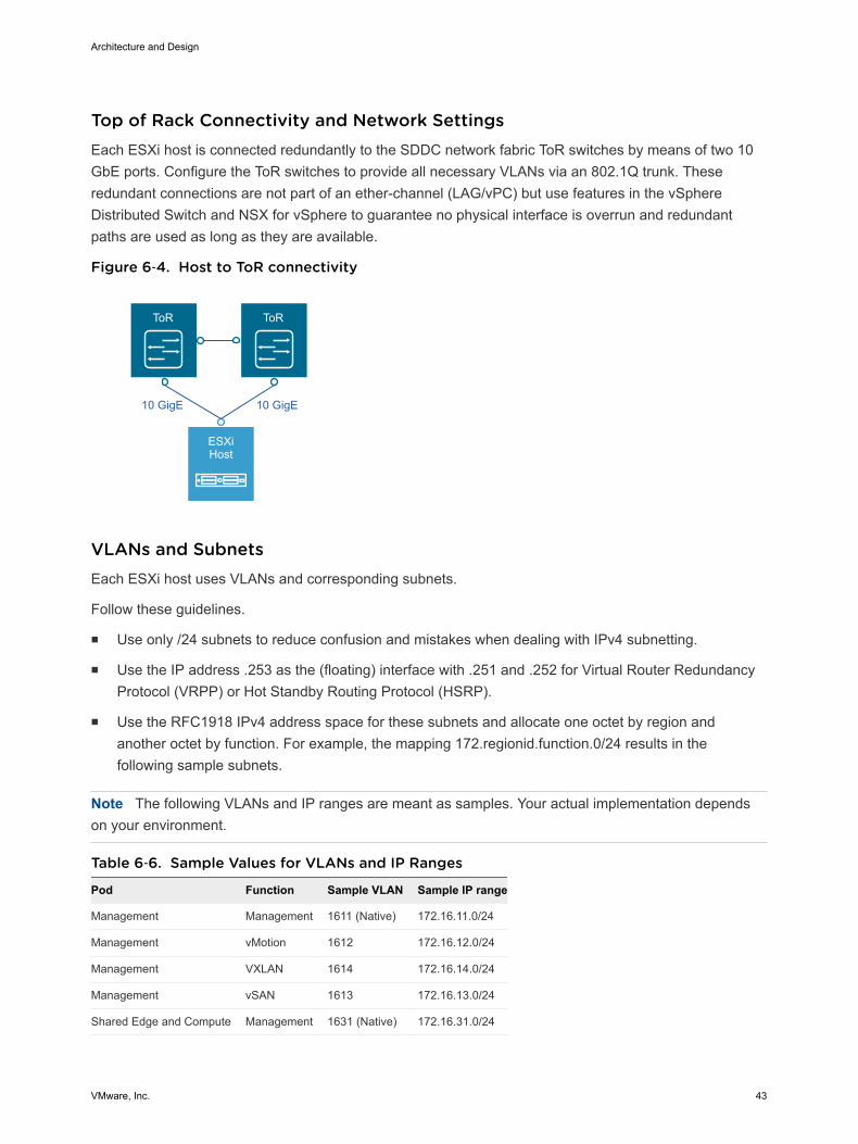
Top of Rack Connectivity and Network SettingsEach ESXi host is connected redundantly to the SDDC network fabric ToR switches by means of two 10GbE ports. Configure the ToR switches to provide all necessary VLANs via an 802.1Q trunk. Theseredundant connections are not part of an ether-channel (LAG/vPC) but use features in the vSphereDistributed Switch and NSX for vSphere to guarantee no physical interface is overrun and redundantpaths are used as long as they are available.
Figure 6‑4. Host to ToR connectivity
ToR ToR
ESXiHost
10 GigE 10 GigE
VLANs and SubnetsEach ESXi host uses VLANs and corresponding subnets.
Follow these guidelines.
n Use only /24 subnets to reduce confusion and mistakes when dealing with IPv4 subnetting.
n Use the IP address .253 as the (floating) interface with .251 and .252 for Virtual Router RedundancyProtocol (VRPP) or Hot Standby Routing Protocol (HSRP).
n Use the RFC1918 IPv4 address space for these subnets and allocate one octet by region andanother octet by function. For example, the mapping 172.regionid.function.0/24 results in thefollowing sample subnets.
Note The following VLANs and IP ranges are meant as samples. Your actual implementation dependson your environment.
Table 6‑6. Sample Values for VLANs and IP Ranges
Pod Function Sample VLAN Sample IP range
Management Management 1611 (Native) 172.16.11.0/24
Management vMotion 1612 172.16.12.0/24
Management VXLAN 1614 172.16.14.0/24
Management vSAN 1613 172.16.13.0/24
Shared Edge and Compute Management 1631 (Native) 172.16.31.0/24
Architecture and Design
VMware, Inc. 43
Table 6‑6. Sample Values for VLANs and IP Ranges(Continued)
Pod Function Sample VLAN Sample IP range
Shared Edge and Compute vMotion 1632 172.16.32.0/24
Shared Edge and Compute VXLAN 1634 172.16.34.0/24
Shared Edge and Compute vSAN 1633 172.16.33.0/24
Access Port Network SettingsConfigure additional network settings on the access ports that connect the leaf switch to thecorresponding servers.
Spanning-Tree Protocol(STP)
Although this design does not use the spanning tree protocol, switchesusually come with STP configured by default. Designate the access portsas trunk PortFast.
Trunking Configure the VLANs as members of a 802.1Q trunk with the managementVLAN acting as the native VLAN.
MTU Set MTU for all VLANS and SVIs (Management, vMotion, VXLAN andStorage) to jumbo frames for consistency purposes.
DHCP helper Configure the VIF of the Management, vMotion and VXLAN subnet as aDHCP proxy.
Multicast Configure IGMP snooping on the ToR switches and include an IGMPquerier on each VLAN.
Region InterconnectivityThe SDDC management networks, VXLAN kernel ports and the edge and compute VXLAN kernelports of the two regions must be connected. These connections can be over a VPN tunnel, Point to Pointcircuits, MPLS, etc. End users must be able to reach the public-facing network segments (publicmanagement and tenant networks) of both regions.
The region interconnectivity design must support jumbo frames, and ensure latency is less than 150 ms.For more details on the requirements for region interconnectivity see the Cross-VC NSX Design Guide.
The design of a region connection solution is out of scope for this VMware Validated Design.
Physical Network Design DecisionsThe physical network design decisions govern the physical layout and use of VLANs. They also includedecisions on jumbo frames and on some other network-related requirements such as DNS and NTP.
Architecture and Design
VMware, Inc. 44
Physical Network Design Decisions
Routing protocols Base the selection of the external routing protocol on your currentimplementation or on available expertise among the IT staff. Takeperformance requirements into consideration. Possible options are OSPF,BGP and IS-IS. While each routing protocol has a complex set of pros andcons, the VVD utilizes BGP as its routing protocol.
DHCP proxy The DHCP proxy must point to a DHCP server by way of its IPv4 address.See the Planning and Preparation documentation for details on the DHCPserver.
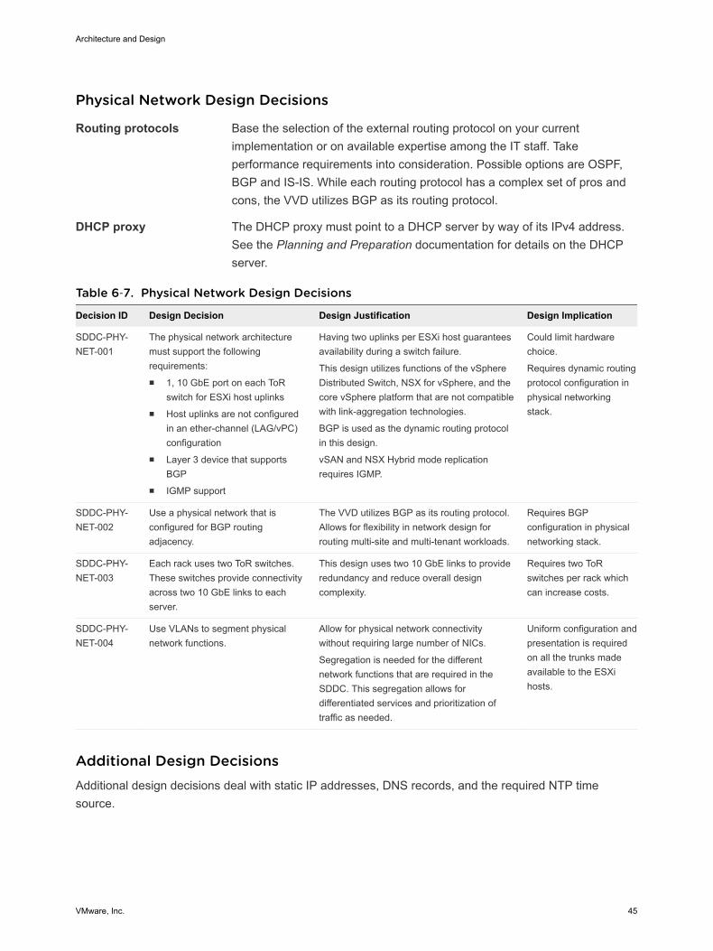
Table 6‑7. Physical Network Design Decisions
Decision ID Design Decision Design Justification Design Implication
SDDC-PHY-NET-001
The physical network architecturemust support the followingrequirements:n 1, 10 GbE port on each ToR
switch for ESXi host uplinksn Host uplinks are not configured
in an ether-channel (LAG/vPC)configuration
n Layer 3 device that supportsBGP
n IGMP support
Having two uplinks per ESXi host guaranteesavailability during a switch failure.
This design utilizes functions of the vSphereDistributed Switch, NSX for vSphere, and thecore vSphere platform that are not compatiblewith link-aggregation technologies.
BGP is used as the dynamic routing protocolin this design.
vSAN and NSX Hybrid mode replicationrequires IGMP.
Could limit hardwarechoice.
Requires dynamic routingprotocol configuration inphysical networkingstack.
SDDC-PHY-NET-002
Use a physical network that isconfigured for BGP routingadjacency.
The VVD utilizes BGP as its routing protocol.Allows for flexibility in network design forrouting multi-site and multi-tenant workloads.
Requires BGPconfiguration in physicalnetworking stack.
SDDC-PHY-NET-003
Each rack uses two ToR switches.These switches provide connectivityacross two 10 GbE links to eachserver.
This design uses two 10 GbE links to provideredundancy and reduce overall designcomplexity.
Requires two ToRswitches per rack whichcan increase costs.
SDDC-PHY-NET-004
Use VLANs to segment physicalnetwork functions.
Allow for physical network connectivitywithout requiring large number of NICs.
Segregation is needed for the differentnetwork functions that are required in theSDDC. This segregation allows fordifferentiated services and prioritization oftraffic as needed.
Uniform configuration andpresentation is requiredon all the trunks madeavailable to the ESXihosts.
Additional Design DecisionsAdditional design decisions deal with static IP addresses, DNS records, and the required NTP timesource.
Architecture and Design
VMware, Inc. 45
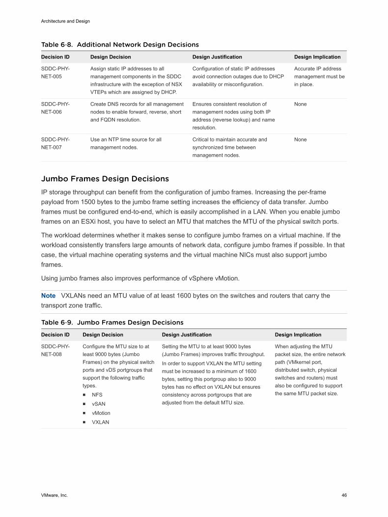
Table 6‑8. Additional Network Design Decisions
Decision ID Design Decision Design Justification Design Implication
SDDC-PHY-NET-005
Assign static IP addresses to allmanagement components in the SDDCinfrastructure with the exception of NSXVTEPs which are assigned by DHCP.
Configuration of static IP addressesavoid connection outages due to DHCPavailability or misconfiguration.
Accurate IP addressmanagement must bein place.
SDDC-PHY-NET-006
Create DNS records for all managementnodes to enable forward, reverse, shortand FQDN resolution.
Ensures consistent resolution ofmanagement nodes using both IPaddress (reverse lookup) and nameresolution.
None
SDDC-PHY-NET-007
Use an NTP time source for allmanagement nodes.
Critical to maintain accurate andsynchronized time betweenmanagement nodes.
None
Jumbo Frames Design DecisionsIP storage throughput can benefit from the configuration of jumbo frames. Increasing the per-framepayload from 1500 bytes to the jumbo frame setting increases the efficiency of data transfer. Jumboframes must be configured end-to-end, which is easily accomplished in a LAN. When you enable jumboframes on an ESXi host, you have to select an MTU that matches the MTU of the physical switch ports.
The workload determines whether it makes sense to configure jumbo frames on a virtual machine. If theworkload consistently transfers large amounts of network data, configure jumbo frames if possible. In thatcase, the virtual machine operating systems and the virtual machine NICs must also support jumboframes.
Using jumbo frames also improves performance of vSphere vMotion.
Note VXLANs need an MTU value of at least 1600 bytes on the switches and routers that carry thetransport zone traffic.
Table 6‑9. Jumbo Frames Design Decisions
Decision ID Design Decision Design Justification Design Implication
SDDC-PHY-NET-008
Configure the MTU size to atleast 9000 bytes (JumboFrames) on the physical switchports and vDS portgroups thatsupport the following traffictypes.n NFSn vSANn vMotionn VXLAN
Setting the MTU to at least 9000 bytes(Jumbo Frames) improves traffic throughput.
In order to support VXLAN the MTU settingmust be increased to a minimum of 1600bytes, setting this portgroup also to 9000bytes has no effect on VXLAN but ensuresconsistency across portgroups that areadjusted from the default MTU size.
When adjusting the MTUpacket size, the entire networkpath (VMkernel port,distributed switch, physicalswitches and routers) mustalso be configured to supportthe same MTU packet size.
Architecture and Design
VMware, Inc. 46
Physical Storage DesignThe VMware Validated Designs utilize different types of storage, and the "Shared Storage Design" sectionexplains where the SDDC uses each and gives background information. The focus of this section isphysical storage design.
All functional testing and validation of the designs is done using vSAN. Although the VMware ValidatedDesigns highly recommend the use of vSAN, in particular for the management pods, any supportedstorage solution may be utilized.
If a storage solution other than vSAN is chosen, you must take into account that all the design,deployment, and day 2 guidance in the VMware Validated Design applies under the context of vSAN andadjust appropriately. Your storage design must match or exceed the capacity and performancecapabilities of the vSAN configuration in the designs.
vSAN Physical DesignSoftware-defined storage is a key technology in the SDDC. This design uses VMware Virtual SAN (vSAN)to implement software-defined storage for the management clusters.
vSAN is a fully integrated hypervisor-converged storage software. vSAN creates a cluster of server harddisk drives and solid state drives, and presents a flash-optimized, highly resilient, shared storagedatastore to hosts and virtual machines. vSAN allows you to control capacity, performance, andavailability on a per virtual machine basis through the use of storage policies.
Requirements and DependenciesThe software-defined storage module has the following requirements and options.
n Minimum of 3 hosts providing storage resources to the vSAN cluster.
n vSAN is configured as hybrid storage or all-flash storage.
n A vSAN hybrid storage configuration requires both magnetic devices and flash caching devices.
n An All-Flash vSAN configuration requires vSphere 6.0 or later.
n Each ESXi host that provides storage resources to the cluster must meet the following requirements.
n Minimum of one SSD. The SSD flash cache tier should be at least 10% of the size of the HDDcapacity tier.
n Minimum of two HHDs.
n RAID controller compatible with vSAN.
n 10 Gbps network for vSAN traffic \ with Multicast enabled.
n vSphere High Availability Isolation Response set to power off virtual machines. With this setting,no possibility of split brain conditions in case of isolation or network partition exists. In a split-braincondition, the virtual machine might be powered on by two hosts by mistake. See design decision SDDC-VI-VC-012 for more details.
Architecture and Design
VMware, Inc. 47
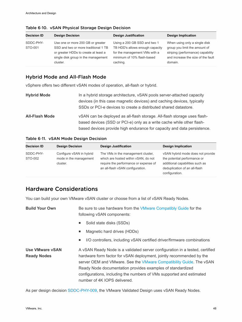
Table 6‑10. vSAN Physical Storage Design Decision
Decision ID Design Decision Design Justification Design Implication
SDDC-PHY-STO-001
Use one or more 200 GB or greaterSSD and two or more traditional 1 TBor greater HDDs to create at least asingle disk group in the managementcluster.
Using a 200 GB SSD and two 1TB HDD's allows enough capacityfor the management VMs with aminimum of 10% flash-basedcaching.
When using only a single diskgroup you limit the amount ofstriping (performance) capabilityand increase the size of the faultdomain.
Hybrid Mode and All-Flash ModevSphere offers two different vSAN modes of operation, all-flash or hybrid.
Hybrid Mode In a hybrid storage architecture, vSAN pools server-attached capacitydevices (in this case magnetic devices) and caching devices, typicallySSDs or PCI-e devices to create a distributed shared datastore.
All-Flash Mode vSAN can be deployed as all-flash storage. All-flash storage uses flash-based devices (SSD or PCI-e) only as a write cache while other flash-based devices provide high endurance for capacity and data persistence.
Table 6‑11. vSAN Mode Design Decision
Decision ID Design Decision Design Justification Design Implication
SDDC-PHY-STO-002
Configure vSAN in hybridmode in the managementcluster.
The VMs in the management cluster,which are hosted within vSAN, do notrequire the performance or expense ofan all-flash vSAN configuration.
vSAN hybrid mode does not providethe potential performance oradditional capabilities such asdeduplication of an all-flashconfiguration.
Hardware ConsiderationsYou can build your own VMware vSAN cluster or choose from a list of vSAN Ready Nodes.
Build Your Own Be sure to use hardware from the VMware Compatibly Guide for thefollowing vSAN components:
n Solid state disks (SSDs)
n Magnetic hard drives (HDDs)
n I/O controllers, including vSAN certified driver/firmware combinations
Use VMware vSANReady Nodes
A vSAN Ready Node is a validated server configuration in a tested, certifiedhardware form factor for vSAN deployment, jointly recommended by theserver OEM and VMware. See the VMware Compatibility Guide. The vSANReady Node documentation provides examples of standardizedconfigurations, including the numbers of VMs supported and estimatednumber of 4K IOPS delivered.
As per design decision SDDC-PHY-009, the VMware Validated Design uses vSAN Ready Nodes.
Architecture and Design
VMware, Inc. 48
Solid State Disk (SSD) CharacteristicsIn a VMware vSAN configuration, the SSDs are used for the vSAN caching layer for hybrid deploymentsand for the capacity layer for all flash.
n For a hybrid deployment, the use of the SSD is split between a non-volatile write cache(approximately 30%) and a read buffer (approximately 70%). As a result, the endurance and thenumber of I/O operations per second that the SSD can sustain are important performance factors.
n For an all-flash model, endurance and performance have the same criteria. However, many morewrite operations are held by the caching tier, thus elongating or extending the life of the SSDcapacity-tier.
SSD Endurance
This VMware Validated Design uses class D endurance class SSDs for the caching tier.
SDDC Endurance Design Decision Background
For endurance of the SSDs used for vSAN, standard industry write metrics are the primarymeasurements used to gauge the reliability of the drive. No standard metric exists across all vendors,however, Drive Writes per Day (DWPD) or Petabytes Written (PBW) are the measurements normallyused.
For vSphere 5.5, the endurance class was based on Drive Writes Per Day (DWPD). For VMware vSAN6.0 and later, the endurance class has been updated to use Terabytes Written (TBW), based on thevendor’s drive warranty. TBW can be used for VMware vSAN 5.5, VMware vSAN 6.0, and VMware vSAN6.5 and is reflected in the VMware Compatibility Guide.
The reasoning behind using TBW is that VMware provides the flexibility to use larger capacity drives withlower DWPD specifications.
If an SSD vendor uses Drive Writes Per Day as a measurement, you can calculate endurance inTerabytes Written (TBW) with the following equation.
TBW (over 5 years) = Drive Size x DWPD x 365 x 5
For example, if a vendor specified DWPD = 10 for an 800 GB capacity SSD, you can compute TBW withthe following equation.
TBW = 0.4TB X 10DWPD X 365days X 5yrs
TBW = 7300TBW
That means the SSD supports 7300 TB writes over 5 years (The higher the TBW number, the greater theendurance class.).
For SSDs that are designated for caching and all-flash capacity layers, the following table outlines whichendurance class to use for hybrid and for all-flash VMware vSAN.
Architecture and Design
VMware, Inc. 49
Endurance Class TBW Hybrid Caching Tier All-Flash Caching Tier All-Flash Capacity Tier
Class A >=365 No No Yes
Class B >=1825 Yes No Yes
Class C >=3650 Yes Yes Yes
Class D >=7300 Yes Yes Yes
Note This VMware Validated Design does not use All-Flash vSAN.
Table 6‑12. SSD Endurance Class Design Decisions
Decision ID Design Decision Design Justification Design Implication
SDDC-PHY-STO-003
Use Class D (>=7300TBW)SSDs for the caching tier of themanagement cluster.
If an SSD designated for the caching tierfails due to wear-out, the entire VMwarevSAN disk group becomes unavailable. Theresult is potential data loss or operationalimpact.
SSDs with higher endurancemay be more expensivethan lower enduranceclasses.
SSD PerformanceThere is a direct correlation between the SSD performance class and the level of vSAN performance. Thehighest-performing hardware results in the best performance of the solution. Cost is therefore thedetermining factor. A lower class of hardware that is more cost effective might be attractive even if theperformance or size is not ideal.
For optimal performance of vSAN, select class E or greater SSDs. See the VMware Compatibility Guidefor detail on the different classes.
SSD Performance Design Decision Background
Select a high class of SSD for optimal performance of VMware vSAN. Before selecting a drive size,consider disk groups and sizing as well as expected future growth. VMware defines classes ofperformance in the VMware Compatibility Guide as follows.
Table 6‑13. SSD Performance Classes
Performance Class Writes Per Second
Class A 2,500 – 5,000
Class B 5,000 – 10,000
Class C 10,000 – 20,000
Class D 20,000 – 30,000
Class E 30,000 – 100,000
Class F 100,000 +
Select an SSD size that is, at a minimum, 10% of the anticipated size of the consumed HDD storagecapacity, before failures to tolerate are considered. For example, select an SSD of at least 100 GB for 1TB of HDD storage consumed in a 2 TB disk group.
Architecture and Design
VMware, Inc. 50
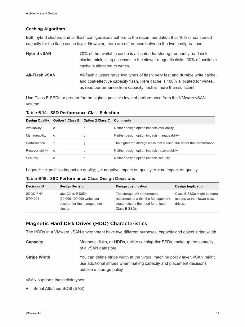
Caching Algorithm
Both hybrid clusters and all-flash configurations adhere to the recommendation that 10% of consumedcapacity for the flash cache layer. However, there are differences between the two configurations.
Hybrid vSAN 70% of the available cache is allocated for storing frequently read diskblocks, minimizing accesses to the slower magnetic disks. 30% of availablecache is allocated to writes.
All-Flash vSAN All-flash clusters have two types of flash: very fast and durable write cache,and cost-effective capacity flash. Here cache is 100% allocated for writes,as read performance from capacity flash is more than sufficient.
Use Class E SSDs or greater for the highest possible level of performance from the VMware vSANvolume.
Table 6‑14. SSD Performance Class Selection
Design Quality Option 1 Class E Option 2 Class C Comments
Availability o o Neither design option impacts availability.
Manageability o o Neither design option impacts manageability.
Performance ↑ ↓ The higher the storage class that is used, the better the performance.
Recover-ability o o Neither design option impacts recoverability.
Security o o Neither design option impacts security.
Legend: ↑ = positive impact on quality; ↓ = negative impact on quality; o = no impact on quality.
Table 6‑15. SSD Performance Class Design Decisions
Decision ID Design Decision Design Justification Design Implication
SDDC-PHY-STO-004
Use Class E SSDs(30,000-100,000 writes persecond) for the managementcluster.
The storage I/O performancerequirements within the Managementcluster dictate the need for at leastClass E SSDs.
Class E SSDs might be moreexpensive than lower classdrives.
Magnetic Hard Disk Drives (HDD) CharacteristicsThe HDDs in a VMware vSAN environment have two different purposes, capacity and object stripe width.
Capacity Magnetic disks, or HDDs, unlike caching-tier SSDs, make up the capacityof a vSAN datastore
Stripe Width You can define stripe width at the virtual machine policy layer. vSAN mightuse additional stripes when making capacity and placement decisionsoutside a storage policy.
vSAN supports these disk types:
n Serial Attached SCSI (SAS)
Architecture and Design
VMware, Inc. 51
n Near Line Serial Attached SCSI (NL-SCSI). NL-SAS can be thought of as enterprise SATA drives butwith a SAS interface.
n Serial Advanced Technology Attachment (SATA). Use SATA magnetic disks only in capacity-centricenvironments where performance is not prioritized.
SAS and NL-SAS get you the best results. This VMware Validated Design uses 10,000 RPM drives toachieve a balance between cost and availability.
HDD Capacity, Cost, and Availability Background Considerations
You can achieve the best results with SAS and NL-SAS.
The VMware vSAN design must consider the number of magnetic disks required for the capacity layer,and how well the capacity layer performs.
n SATA disks typically provide more capacity per individual drive, and tend to be less expensive thanSAS drives. However, the trade-off is performance, because SATA performance is not as good asSAS performance due to lower rotational speeds (typically 7200 RPM)
n In environments where performance is critical, choose SAS magnetic disks instead of SATA magneticdisks.
Consider that failure of a larger capacity drive has operational impact on the availability and recoveryof more components.
Rotational Speed (RPM) Background Considerations
HDDs tend to be more reliable, but that comes at a cost. SAS disks can be available up to 15,000 RPMspeeds.
Table 6‑16. vSAN HDD Environmental Characteristics
Characteristic Revolutions per Minute (RPM)
Capacity 7,200
Performance 10,000
Additional Performance 15,000
Cache-friendly workloads are less sensitive to disk performance characteristics; however, workloads canchange over time. HDDs with 10,000 RPM are the accepted norm when selecting a capacity tier.
For the software-defined storage module, VMware recommends that you use an HDD configuration thatis suited to the characteristics of the environment. If there are no specific requirements, selecting 10,000RPM drives achieves a balance between cost and availability.
Architecture and Design
VMware, Inc. 52
Table 6‑17. HDD Selection Design Decisions
Decision ID Design Decision Design Justification Design Implication
SDDC-PHY-STO-005
Use 10,000 RPM HDDsfor the managementcluster.
10,000 RPM HDDs achieve a balance betweenperformance and availability for the VMware vSANconfiguration.
The performance of 10,000 RPM HDDs avoids diskdrain issues. In vSAN hybrid mode, the vSANperiodically flushes uncommitted writes to thecapacity tier.
Slower and potentiallycheaper HDDs are notavailable.
I/O ControllersThe I/O controllers are as important to a VMware vSAN configuration as the selection of disk drives.vSAN supports SAS, SATA, and SCSI adapters in either pass-through or RAID 0 mode. vSAN supportsmultiple controllers per host.
n Multiple controllers can improve performance and mitigate a controller or SSD failure to a smallernumber of drives or vSAN disk groups.
n With a single controller, all disks are controlled by one device. A controller failure impacts all storage,including the boot media (if configured).
Controller queue depth is possibly the most important aspect for performance. All I/O controllers inthe VMware vSAN Hardware Compatibility Guide have a minimum queue depth of 256. Consider normalday-to-day operations and increase of I/O due to Virtual Machine deployment operations or re-sync I/Oactivity as a result of automatic or manual fault remediation.
About SAS ExpandersSAS expanders are a storage technology that lets you maximize the storage capability of your SAScontroller card. Like switches of an Ethernet network, SAS expanders enable you to connect a largernumber of devices, that is, more SAS/SATA devices to a single SAS controller. Many SAS controllerssupport up to 128 or more hard drives.
Caution VMware has not extensively tested SAS expanders, as a result performance and operationalpredictability are relatively unknown at this point. For this reason, you should avoid configurations withSAS expanders.
NFS Physical Storage DesignNetwork File System (NFS) is a distributed file system protocol that allows a user on a client computer toaccess files over a network much like local storage is accessed. In this case, the client computer is anESXi host, and the storage is provided by an NFS-capable external storage array.
The management cluster uses VMware vSAN for primary storage and NFS for secondary storage. Thecompute clusters are not restricted to any particular storage technology. For compute clusters, thedecision on which technology to use is based on the performance, capacity, and capabilities (replication,deduplication, compression, etc.) required by the workloads that are running in the clusters.
Architecture and Design
VMware, Inc. 53
Table 6‑18. NFS Usage Design Decisions
Decision ID Design Decision Design Justification Design Implication
SDDC-PHY-STO-006
NFS storage is presented to provide thefollowing features.n A datastore for backup datan An export for archive datan A datastore for templates and ISOs
Separate primary virtual machinestorage from backup data in case ofprimary storage failure.
vRealize Log Insight archivingrequires a NFS export.
An NFS capableexternal array isrequired.
RequirementsYour environment must meet the following requirements to use NFS storage in the VMware ValidatedDesign.
n Storage arrays are connected directly to the leaf switches.
n All connections are made using 10 Gb Ethernet.
n Jumbo Frames are enabled.
n 10K SAS (or faster) drives are used in the storage array.
Different disk speeds and disk types can be combined in an array to create different performance andcapacity tiers. The management cluster uses 10K SAS drives in the RAID configuration recommended bythe array vendor to achieve the required capacity and performance.
Table 6‑19. NFS Hardware Design Decision
Decision ID Design Decision Design Justification Design Implication
SDDC-PHY-STO-007
Use 10K SAS drivesfor NFS volumes.
10K SAS drives achieve a balance betweenperformance and capacity. Faster drives can be usedif desired.
vRealize Log Insight uses NFS datastores for itsarchive storage which, depending on complianceregulations, can use a large amount of disk space.
10K SAS drives aregenerally more expensivethan other alternatives.
VolumesA volume consists of multiple disks in a storage array that RAID is applied to.
Multiple datastores can be created on a single volume, but for applications that do not have a high I/Ofootprint a single volume with multiple datastores is sufficient.
n For high I/O applications, such as backup applications, use a dedicated volume to avoid performanceissues.
n For other applications, set up Storage I/O Control (SIOC) to impose limits on high I/O applications sothat other applications get the I/O they are requesting.
Architecture and Design
VMware, Inc. 54
Table 6‑20. Volume Assignment Design Decisions
Decision ID Design Decision Design Justification Design Implication
SDDC-PHY-STO-008
Use a dedicated NFSvolume to support backuprequirements.
The backup and restore process is I/Ointensive. Using a dedicated NFSvolume ensures that the process doesnot impact the performance of othermanagement components.
Dedicated volumes add managementoverhead to storage administrators.Dedicated volumes might use moredisks, depending on the array andtype of RAID.
SDDC-PHY-STO-009
Use a shared volume forother managementcomponent datastores.
Non-backup related managementapplications can share a commonvolume due to the lower I/O profile ofthese applications.
Enough storage space for sharedvolumes and their associatedapplication data must be available.
Architecture and Design
VMware, Inc. 55
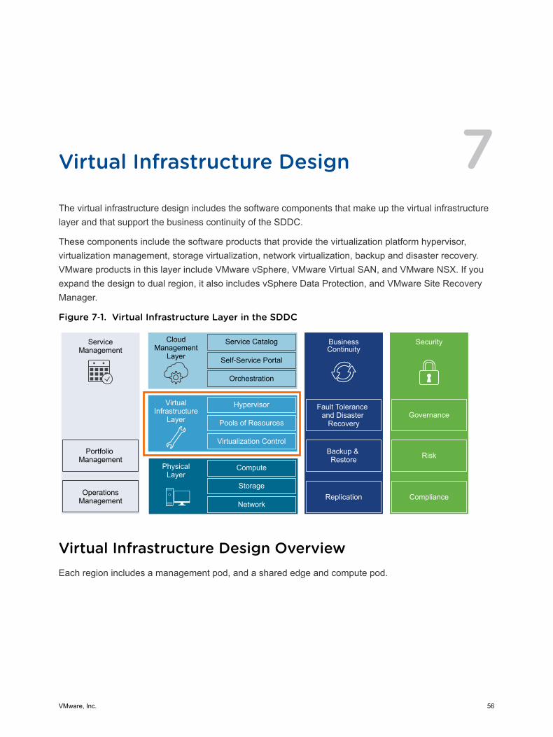
Virtual Infrastructure Design 7The virtual infrastructure design includes the software components that make up the virtual infrastructurelayer and that support the business continuity of the SDDC.
These components include the software products that provide the virtualization platform hypervisor,virtualization management, storage virtualization, network virtualization, backup and disaster recovery.VMware products in this layer include VMware vSphere, VMware Virtual SAN, and VMware NSX. If youexpand the design to dual region, it also includes vSphere Data Protection, and VMware Site RecoveryManager.
Figure 7‑1. Virtual Infrastructure Layer in the SDDC
ServiceManagement
Portfolio Management
OperationsManagement
CloudManagement
Layer
Service Catalog
Self-Service Portal
Orchestration
BusinessContinuity
Fault Tolerance and Disaster
Recovery
Backup & Restore
Hypervisor
Pools of Resources
Virtualization Control
VirtualInfrastructure
Layer
Compute
Storage
Network
PhysicalLayer
Security
Replication Compliance
Risk
Governance
Virtual Infrastructure Design OverviewEach region includes a management pod, and a shared edge and compute pod.
VMware, Inc. 56
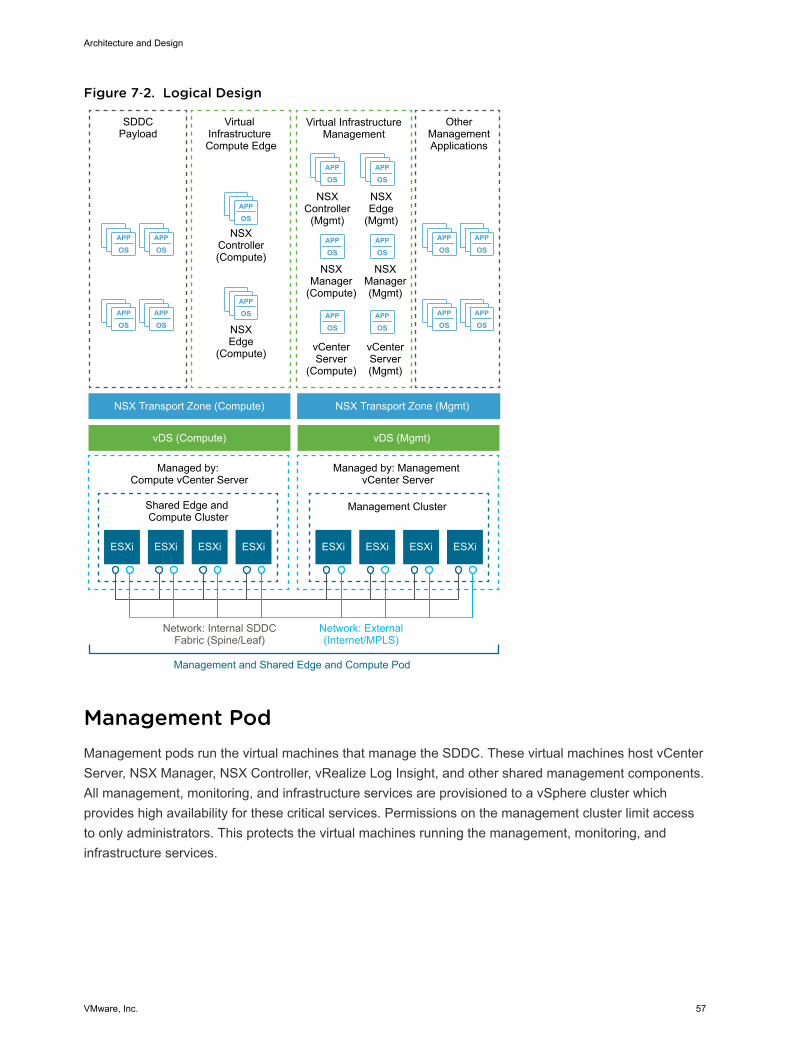
Figure 7‑2. Logical Design
APP
OSAPP
OS
APP
OSAPP
OS
APP
OSAPP
OS
APP
OSAPP
OS
APP
OS
APP
OS
APP
OSAPP
OS
ESXi ESXi
APP
OSAPP
OS
APP
OSAPP
OS
Virtual InfrastructureManagement
NSXController
(Mgmt)
OtherManagementApplications
NSXEdge
(Mgmt)
NSXManager(Mgmt)
NSXManager
(Compute)
NSXEdge
(Compute)
NSXController(Compute)
ESXi ESXi ESXi ESXi ESXi ESXi
SDDCPayload
Virtual Infrastructure Compute Edge
NSX Transport Zone (Compute)
vDS (Compute) vDS (Mgmt)
NSX Transport Zone (Mgmt)
Shared Edge and Compute Cluster
Management Cluster
Managed by: Compute vCenter Server
Managed by: Management vCenter Server
Network: External(Internet/MPLS)
Network: Internal SDDCFabric (Spine/Leaf)
Management and Shared Edge and Compute Pod
vCenterServer(Mgmt)
vCenterServer
(Compute)
Management PodManagement pods run the virtual machines that manage the SDDC. These virtual machines host vCenterServer, NSX Manager, NSX Controller, vRealize Log Insight, and other shared management components.All management, monitoring, and infrastructure services are provisioned to a vSphere cluster whichprovides high availability for these critical services. Permissions on the management cluster limit accessto only administrators. This protects the virtual machines running the management, monitoring, andinfrastructure services.
Architecture and Design
VMware, Inc. 57
Shared Edge and Compute PodThe virtual infrastructure design uses a shared edge and compute pod. The shared pod combines thecharacteristics of typical edge and compute pods into a single pod. It is possible to separate these in thefuture if required.
This pod provides the following main functions:
n Supports on-ramp and off-ramp connectivity to physical networks
n Connects with VLANs in the physical world
n Hosts the SDDC tenant virtual machines
The shared edge and compute pod connects the virtual networks (overlay networks) provided by NSX forvSphere and the external networks. An SDDC can mix different types of compute-only pods and provideseparate compute pools for different types of SLAs.
This chapter includes the following topics:
n ESXi Design
n vCenter Server Design
n vSphere Cluster Design
n vCenter Server Customization
n Use of Transport Layer Security (TLS) Certificates
n Virtualization Network Design
n NSX Design
n Shared Storage Design
ESXi DesignThe ESXi design includes design decisions for boot options, user access, and the virtual machine swapconfiguration.
ESXi Hardware RequirementsYou can find the ESXi hardware requirements in Physical Design Fundamentals. The following designoutlines the design of the ESXi configuration.
Architecture and Design
VMware, Inc. 58
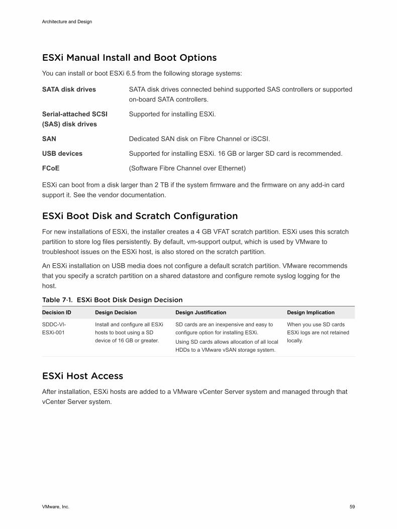
ESXi Manual Install and Boot OptionsYou can install or boot ESXi 6.5 from the following storage systems:
SATA disk drives SATA disk drives connected behind supported SAS controllers or supportedon-board SATA controllers.
Serial-attached SCSI(SAS) disk drives
Supported for installing ESXi.
SAN Dedicated SAN disk on Fibre Channel or iSCSI.
USB devices Supported for installing ESXi. 16 GB or larger SD card is recommended.
FCoE (Software Fibre Channel over Ethernet)
ESXi can boot from a disk larger than 2 TB if the system firmware and the firmware on any add-in cardsupport it. See the vendor documentation.
ESXi Boot Disk and Scratch ConfigurationFor new installations of ESXi, the installer creates a 4 GB VFAT scratch partition. ESXi uses this scratchpartition to store log files persistently. By default, vm-support output, which is used by VMware totroubleshoot issues on the ESXi host, is also stored on the scratch partition.
An ESXi installation on USB media does not configure a default scratch partition. VMware recommendsthat you specify a scratch partition on a shared datastore and configure remote syslog logging for thehost.
Table 7‑1. ESXi Boot Disk Design Decision
Decision ID Design Decision Design Justification Design Implication
SDDC-VI-ESXi-001
Install and configure all ESXihosts to boot using a SDdevice of 16 GB or greater.
SD cards are an inexpensive and easy toconfigure option for installing ESXi.
Using SD cards allows allocation of all localHDDs to a VMware vSAN storage system.
When you use SD cardsESXi logs are not retainedlocally.
ESXi Host AccessAfter installation, ESXi hosts are added to a VMware vCenter Server system and managed through thatvCenter Server system.
Architecture and Design
VMware, Inc. 59
Direct access to the host console is still available and most commonly used for troubleshooting purposes.You can access ESXi hosts directly using one of these three methods:
Direct Console UserInterface (DCUI)
Graphical interface on the console. Allows basic administrative controls andtroubleshooting options.
ESXi Shell A Linux-style bash login on the ESXi console itself.
Secure Shell (SSH)Access
Remote command-line console access.
You can enable or disable each method. By default the ESXi Shell and SSH are disabled to secure theESXi host. The DCUI is disabled only if Strict Lockdown Mode is enabled.
ESXi User AccessBy default, root is the only user who can log in to an ESXi host directly, however, you can add ESXi hoststo an Active Directory domain. After the host has been added to an Active Directory domain, access canbe granted through Active Directory groups. Auditing who has logged into the host also becomes easier.
Table 7‑2. ESXi User Access Design Decisions
Decision ID Design Decision Design Justification Design Implication
SDDC-VI-ESXi-002
Add each host to the Active Directorydomain for the region in which it willreside.
Using Active Directory membership allowsgreater flexibility in granting access toESXi hosts.
Ensuring that users log in with a uniqueuser account allows greater visibility forauditing.
Adding hosts to thedomain can add someadministrative overhead.
SDDC-VI-ESXi-003
Change the default ESX Adminsgroup to the SDDC-Admins ActiveDirectory group. Add ESXiadministrators to the SDDC-Adminsgroup following standard accessprocedures.
Having an SDDC-Admins group is moresecure because it removes a knownadministrative access point. In additiondifferent groups allow for separation ofmanagement tasks.
Additional changes to thehost's advanced settingsare required.
Virtual Machine Swap ConfigurationWhen a virtual machine is powered on, the system creates a VMkernel swap file to serve as a backingstore for the virtual machine's RAM contents. The default swap file is stored in the same location as thevirtual machine's configuration file. This simplifies the configuration, however it can cause an excess ofreplication traffic that is not needed.
You can reduce the amount of traffic that is replicated by changing the swap file location to a user-configured location on the host. However, it can take longer to perform VMware vSphere vMotion®
operations when the swap file has to be recreated.
Architecture and Design
VMware, Inc. 60
Table 7‑3. Other ESXi Host Design Decisions
Decision ID Design Decision Design Justification Design Implication
SDDC-VI-ESXi-004
Configure all ESXi hosts tosynchronize time with thecentral NTP servers.
Required because deployment ofvCenter Server Appliance on anESXi host might fail if the host is notusing NTP.
All firewalls located between theESXi host and the NTP servers haveto allow NTP traffic on the requirednetwork ports.
vCenter Server DesignThe vCenter Server design includes both the design for the vCenter Server instance and the VMwarePlatform Services Controller instance.
A Platform Services Controller groups a set of infrastructure services including vCenter Single Sign-On,License service, Lookup Service, and VMware Certificate Authority (VMCA). You can deploy the PlatformServices Controller and the associated vCenter Server system on the same virtual machine(embeddedPlatform Services Controller) or on different virtual machines (external Platform Services Controller).
vCenter Server DeploymentThe design decisions for vCenter Server deployment discuss the number of vCenter Server and PlatformServices Controller instances, the type of installation, and the topology.
Architecture and Design
VMware, Inc. 61
Table 7‑4. vCenter Server Design Decision
Decision ID Design Decision Design JustificationDesignImplication
SDDC-VI-VC-001
Deploy two vCenter Serversystems in the first availabilityzone of each region.n One vCenter Server
supporting the SDDCmanagementcomponents.
n One vCenter Serversupporting the edgecomponents and computeworkloads.
Isolates vCenter Server failures to management or computeworkloads.
Isolates vCenter Server operations between management andcompute.
Supports a scalable cluster design where the managementcomponents may be re-used as additional compute needs tobe added to the SDDC.
Simplifies capacity planning for compute workloads byeliminating management workloads from consideration in theCompute vCenter Server.
Improves the ability to upgrade the vSphere environment andrelated components by providing for explicit separation ofmaintenance windows:n Management workloads remain available while workloads
in compute are being addressedn Compute workloads remain available while workloads in
management are being addressed
Ability to have clear separation of roles and responsibilitiesto ensure that only those administrators with properauthorization can attend to the management workloads.
Facilitates quicker troubleshooting and problem resolution.
Simplifies Disaster Recovery operations by supporting aclear demarcation between recovery of the managementcomponents and compute workloads.
Enables the use of two NSX managers, one for themanagement pod and the other for the shared edge andcompute pod. Network separation of the pods in the SDDCallows for isolation of potential network issues.
Requireslicenses for eachvCenter Serverinstance.
You can install vCenter Server as a Windows-based system or deploy the Linux-based VMware vCenterServer Appliance. The Linux-based vCenter Server Appliance is preconfigured, enables fast deployment,and potentially results in reduced Microsoft licensing costs.
Table 7‑5. vCenter Server Platform Design Decision
Decision ID Design Decision Design Justification Design Implication
SDDC-VI-VC-002 Deploy all vCenter Serverinstances as Linux-based vCenterServer Appliances.
Allows for rapid deployment,enables scalability, and reducesMicrosoft licensing costs.
Operational staff might need Linuxexperience to troubleshoot theLinux-based appliances.
Architecture and Design
VMware, Inc. 62
Platform Services Controller Design Decision BackgroundvCenter Server supports installation with an embedded Platform Services Controller (embeddeddeployment) or with an external Platform Services Controller.
n In an embedded deployment, vCenter Server and the Platform Services Controller run on the samevirtual machine. Embedded deployments are recommended for standalone environments with onlyone vCenter Server system.
n Environments with an external Platform Services Controller can have multiple vCenter Serversystems. The vCenter Server systems can use the same Platform Services Controller services. Forexample, several vCenter Server systems can use the same instance of vCenter Single Sign-On forauthentication.
n If there is a need to replicate with other Platform Services Controller instances, or if the solutionincludes more than one vCenter Single Sign-On instance, you can deploy multiple external PlatformServices Controller instances on separate virtual machines.
Table 7‑6. Platform Service Controller Design Decisions
Decision ID Design Decision Design Justification Design Implication
SDDC-VI-VC-003
Deploy each vCenter Serverwith an external PlatformServices Controller.
External Platform Services Controllers arerequired for replication between PlatformServices Controller instances.
The number of VMs that haveto be managed increases.
SDDC-VI-VC-004
Join all Platform ServicesController instances to asingle vCenter Single Sign-On domain.
When all Platform Services Controllerinstances are joined into a single vCenterSingle Sign-On domain, they can shareauthentication and license data across allcomponents and regions.
Only one Single Sign-Ondomain will exist.
SDDC-VI-VC-005
Create a ring topology for thePlatform Service Controllers.
By default, Platform Service Controllers onlyreplicate with one other Platform ServicesController, that creates a single point of failurefor replication. A ring topology ensures eachPlatform Service Controller has tworeplication partners and eliminates any singlepoint of failure.
Command-line interfacecommands must be used toconfigure the ring replicationtopology.
SDDC-VI-VC-006
Use an NSX Edge ServicesGateway as a load balancerfor the Platform ServicesControllers.
Using a load balancer increases theavailability of the PSC’s for all applications.
Configuring the load balancerand repointing vCenter Serverto the load balancers Virtual IP(VIP) creates administrativeoverhead.
Architecture and Design
VMware, Inc. 63
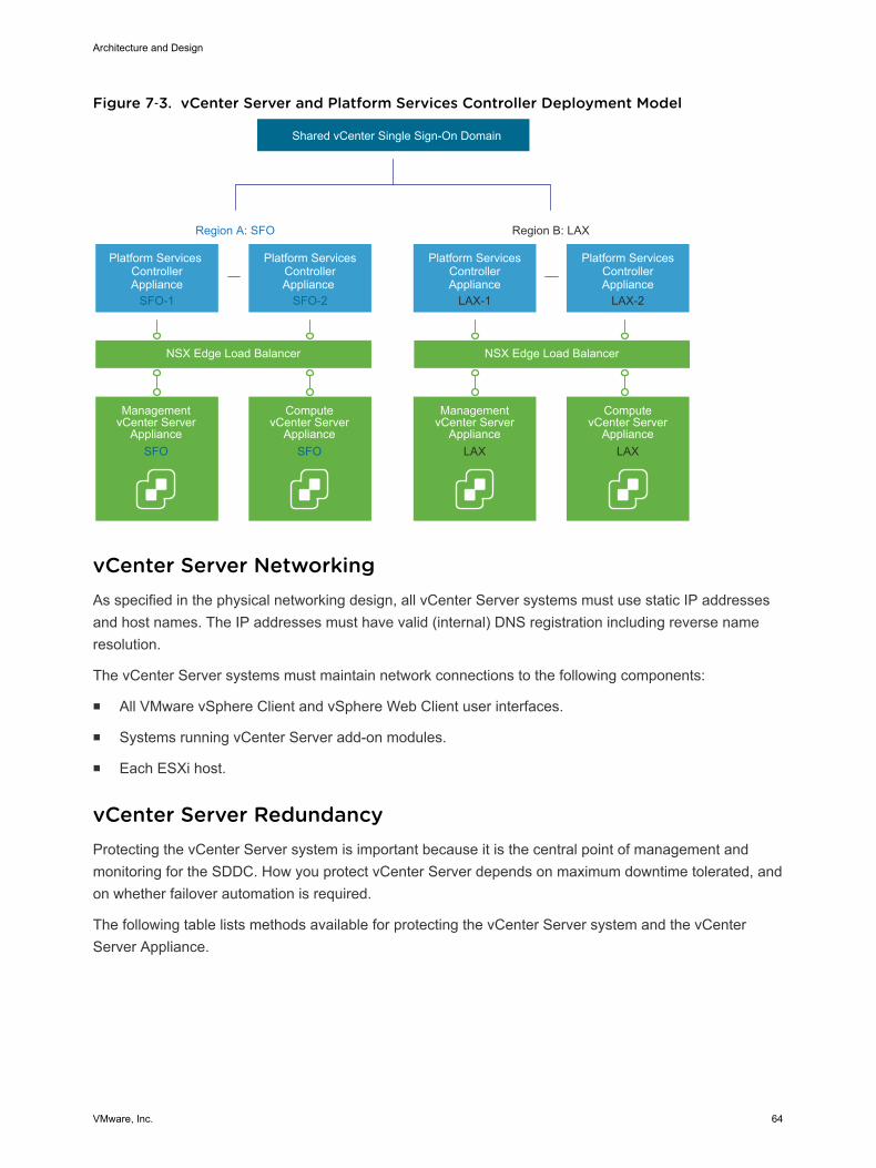
Figure 7‑3. vCenter Server and Platform Services Controller Deployment Model
Region A: SFO Region B: LAX
Platform Services ControllerAppliance
SFO-1
Management vCenter Server
Appliance
Shared vCenter Single Sign-On Domain
Platform ServicesControllerAppliance
SFO-2
NSX Edge Load Balancer NSX Edge Load Balancer
ComputevCenter Server
Appliance
Platform ServicesControllerAppliance
LAX-2
ComputevCenter Server
Appliance
Platform ServicesControllerAppliance
LAX-1
Management vCenter Server
Appliance LAX LAXSFO SFO
vCenter Server NetworkingAs specified in the physical networking design, all vCenter Server systems must use static IP addressesand host names. The IP addresses must have valid (internal) DNS registration including reverse nameresolution.
The vCenter Server systems must maintain network connections to the following components:
n All VMware vSphere Client and vSphere Web Client user interfaces.
n Systems running vCenter Server add-on modules.
n Each ESXi host.
vCenter Server RedundancyProtecting the vCenter Server system is important because it is the central point of management andmonitoring for the SDDC. How you protect vCenter Server depends on maximum downtime tolerated, andon whether failover automation is required.
The following table lists methods available for protecting the vCenter Server system and the vCenterServer Appliance.
Architecture and Design
VMware, Inc. 64
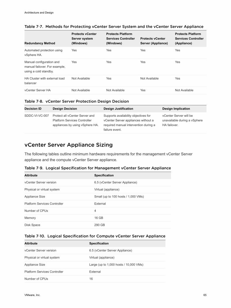
Table 7‑7. Methods for Protecting vCenter Server System and the vCenter Server Appliance
Redundancy Method
Protects vCenterServer system(Windows)
Protects PlatformServices Controller(Windows)
Protects vCenterServer (Appliance)
Protects PlatformServices Controller(Appliance)
Automated protection usingvSphere HA.
Yes Yes Yes Yes
Manual configuration andmanual failover. For example,using a cold standby.
Yes Yes Yes Yes
HA Cluster with external loadbalancer
Not Available Yes Not Available Yes
vCenter Server HA Not Available Not Available Yes Not Available
Table 7‑8. vCenter Server Protection Design Decision
Decision ID Design Decision Design Justification Design Implication
SDDC-VI-VC-007 Protect all vCenter Server andPlatform Services Controllerappliances by using vSphere HA.
Supports availability objectives forvCenter Server appliances without arequired manual intervention during afailure event.
vCenter Server will beunavailable during a vSphereHA failover.
vCenter Server Appliance SizingThe following tables outline minimum hardware requirements for the management vCenter Serverappliance and the compute vCenter Server appliance.
Table 7‑9. Logical Specification for Management vCenter Server Appliance
Attribute Specification
vCenter Server version 6.5 (vCenter Server Appliance)
Physical or virtual system Virtual (appliance)
Appliance Size Small (up to 100 hosts / 1,000 VMs)
Platform Services Controller External
Number of CPUs 4
Memory 16 GB
Disk Space 290 GB
Table 7‑10. Logical Specification for Compute vCenter Server Appliance
Attribute Specification
vCenter Server version 6.5 (vCenter Server Appliance)
Physical or virtual system Virtual (appliance)
Appliance Size Large (up to 1,000 hosts / 10,000 VMs)
Platform Services Controller External
Number of CPUs 16
Architecture and Design
VMware, Inc. 65
Table 7‑10. Logical Specification for Compute vCenter Server Appliance(Continued)
Attribute Specification
Memory 32 GB
Disk Space 640 GB
Table 7‑11. vCenter Server Appliance Sizing Design Decisions
Decision ID Design Decision Design Justification Design Implication
SDDC-VI-VC-008
Configure the managementvCenter Server Applianceswith at least the small sizesetting.
Based on the number of managementVMs that are running, a vCenter ServerAppliance installed with the small sizesetting is sufficient.
If the size of the managementenvironment changes, the vCenterServer Appliance size might needto be increased.
SDDC-VI-VC-009
Configure the computevCenter Server Applianceswith at least the large sizesetting.
Based on the number of computeworkloads and NSX edge devicesrunning, a vCenter Server Applianceinstalled with the large size setting isrecommended.
As the compute environmentgrows resizing to X-Large oradding additional vCenter Serverinstances may be required.
vSphere Cluster DesignThe cluster design must take into account the workload that the cluster handles. Different cluster types inthis design have different characteristics.
vSphere Cluster Design Decision BackgroundThe following heuristics help with cluster design decisions.
n Decide to use fewer, larger hosts or more, smaller hosts.
n A scale-up cluster has fewer, larger hosts.
n A scale-out cluster has more, smaller hosts.
n A virtualized server cluster typically has more hosts with fewer virtual machines per host.
n Compare the capital costs of purchasing fewer, larger hosts with the costs of purchasing more,smaller hosts. Costs vary between vendors and models.
n Evaluate the operational costs of managing a few hosts with the costs of managing more hosts.
n Consider the purpose of the cluster.
n Consider the total number of hosts and cluster limits.
Architecture and Design
VMware, Inc. 66
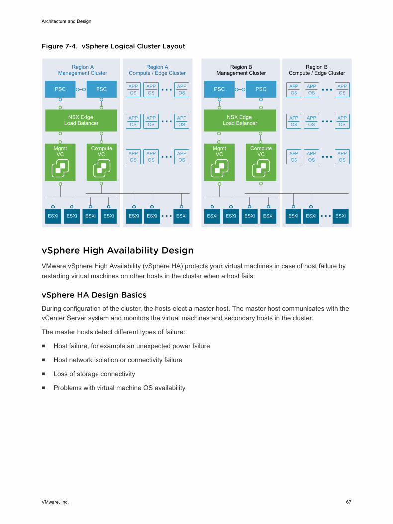
Figure 7‑4. vSphere Logical Cluster Layout
APPOS
APPOS
APPOS
APPOS
APPOS
APPOS
APPOS
APPOS
APPOS
APPOS
APPOS
APPOS
APPOS
APPOS
APPOS
APPOS
APPOS
APPOS
MgmtVC
Region AManagement Cluster
ESXi ESXi ESXi ESXi ESXi ESXi ESXi
Region ACompute / Edge Cluster
Region BManagement Cluster
Region BCompute / Edge Cluster
PSC
NSX Edge Load Balancer
NSX Edge Load Balancer
ComputeVC
PSC
MgmtVC
ESXi ESXi ESXi ESXi ESXi ESXi ESXi
PSC
ComputeVC
PSC
vSphere High Availability DesignVMware vSphere High Availability (vSphere HA) protects your virtual machines in case of host failure byrestarting virtual machines on other hosts in the cluster when a host fails.
vSphere HA Design BasicsDuring configuration of the cluster, the hosts elect a master host. The master host communicates with thevCenter Server system and monitors the virtual machines and secondary hosts in the cluster.
The master hosts detect different types of failure:
n Host failure, for example an unexpected power failure
n Host network isolation or connectivity failure
n Loss of storage connectivity
n Problems with virtual machine OS availability
Architecture and Design
VMware, Inc. 67
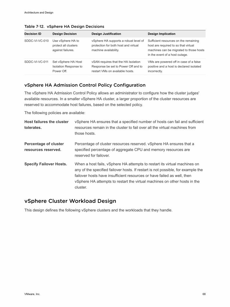
Table 7‑12. vSphere HA Design Decisions
Decision ID Design Decision Design Justification Design Implication
SDDC-VI-VC-010 Use vSphere HA toprotect all clustersagainst failures.
vSphere HA supports a robust level ofprotection for both host and virtualmachine availability.
Sufficient resources on the remaininghost are required to so that virtualmachines can be migrated to those hostsin the event of a host outage.
SDDC-VI-VC-011 Set vSphere HA HostIsolation Response toPower Off.
vSAN requires that the HA IsolationResponse be set to Power Off and torestart VMs on available hosts.
VMs are powered off in case of a falsepositive and a host is declared isolatedincorrectly.
vSphere HA Admission Control Policy ConfigurationThe vSphere HA Admission Control Policy allows an administrator to configure how the cluster judges'available resources. In a smaller vSphere HA cluster, a larger proportion of the cluster resources arereserved to accommodate host failures, based on the selected policy.
The following policies are available:
Host failures the clustertolerates.
vSphere HA ensures that a specified number of hosts can fail and sufficientresources remain in the cluster to fail over all the virtual machines fromthose hosts.
Percentage of clusterresources reserved.
Percentage of cluster resources reserved. vSphere HA ensures that aspecified percentage of aggregate CPU and memory resources arereserved for failover.
Specify Failover Hosts. When a host fails, vSphere HA attempts to restart its virtual machines onany of the specified failover hosts. If restart is not possible, for example thefailover hosts have insufficient resources or have failed as well, thenvSphere HA attempts to restart the virtual machines on other hosts in thecluster.
vSphere Cluster Workload DesignThis design defines the following vSphere clusters and the workloads that they handle.
Architecture and Design
VMware, Inc. 68
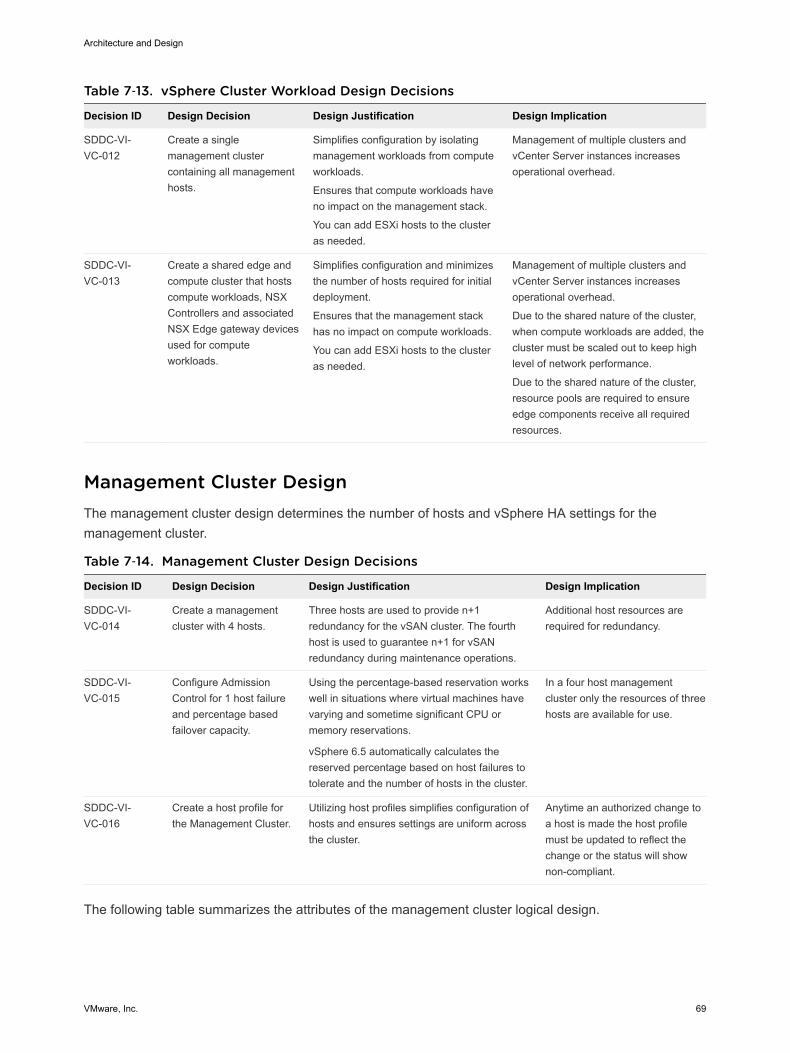
Table 7‑13. vSphere Cluster Workload Design Decisions
Decision ID Design Decision Design Justification Design Implication
SDDC-VI-VC-012
Create a singlemanagement clustercontaining all managementhosts.
Simplifies configuration by isolatingmanagement workloads from computeworkloads.
Ensures that compute workloads haveno impact on the management stack.
You can add ESXi hosts to the clusteras needed.
Management of multiple clusters andvCenter Server instances increasesoperational overhead.
SDDC-VI-VC-013
Create a shared edge andcompute cluster that hostscompute workloads, NSXControllers and associatedNSX Edge gateway devicesused for computeworkloads.
Simplifies configuration and minimizesthe number of hosts required for initialdeployment.
Ensures that the management stackhas no impact on compute workloads.
You can add ESXi hosts to the clusteras needed.
Management of multiple clusters andvCenter Server instances increasesoperational overhead.
Due to the shared nature of the cluster,when compute workloads are added, thecluster must be scaled out to keep highlevel of network performance.
Due to the shared nature of the cluster,resource pools are required to ensureedge components receive all requiredresources.
Management Cluster DesignThe management cluster design determines the number of hosts and vSphere HA settings for themanagement cluster.
Table 7‑14. Management Cluster Design Decisions
Decision ID Design Decision Design Justification Design Implication
SDDC-VI-VC-014
Create a managementcluster with 4 hosts.
Three hosts are used to provide n+1redundancy for the vSAN cluster. The fourthhost is used to guarantee n+1 for vSANredundancy during maintenance operations.
Additional host resources arerequired for redundancy.
SDDC-VI-VC-015
Configure AdmissionControl for 1 host failureand percentage basedfailover capacity.
Using the percentage-based reservation workswell in situations where virtual machines havevarying and sometime significant CPU ormemory reservations.
vSphere 6.5 automatically calculates thereserved percentage based on host failures totolerate and the number of hosts in the cluster.
In a four host managementcluster only the resources of threehosts are available for use.
SDDC-VI-VC-016
Create a host profile forthe Management Cluster.
Utilizing host profiles simplifies configuration ofhosts and ensures settings are uniform acrossthe cluster.
Anytime an authorized change toa host is made the host profilemust be updated to reflect thechange or the status will shownon-compliant.
The following table summarizes the attributes of the management cluster logical design.
Architecture and Design
VMware, Inc. 69
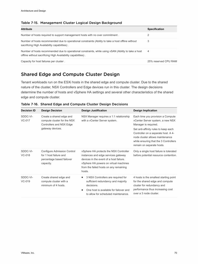
Table 7‑15. Management Cluster Logical Design Background
Attribute Specification
Number of hosts required to support management hosts with no over commitment . 2
Number of hosts recommended due to operational constraints (Ability to take a host offline withoutsacrificing High Availability capabilities) .
3
Number of hosts recommended due to operational constraints, while using vSAN (Ability to take a hostoffline without sacrificing High Availability capabilities) .
4
Capacity for host failures per cluster . 25% reserved CPU RAM
Shared Edge and Compute Cluster DesignTenant workloads run on the ESXi hosts in the shared edge and compute cluster. Due to the sharednature of the cluster, NSX Controllers and Edge devices run in this cluster. The design decisionsdetermine the number of hosts and vSphere HA settings and several other characteristics of the sharededge and compute cluster.
Table 7‑16. Shared Edge and Compute Cluster Design Decisions
Decision ID Design Decision Design Justification Design Implication
SDDC-VI-VC-017
Create a shared edge andcompute cluster for the NSXControllers and NSX Edgegateway devices.
NSX Manager requires a 1:1 relationshipwith a vCenter Server system.
Each time you provision a ComputevCenter Server system, a new NSXManager is required.
Set anti-affinity rules to keep eachController on a separate host. A 4-node cluster allows maintenancewhile ensuring that the 3 Controllersremain on separate hosts.
SDDC-VI-VC-018
Configure Admission Controlfor 1 host failure andpercentage based failovercapacity.
vSphere HA protects the NSX Controllerinstances and edge services gatewaydevices in the event of a host failure.vSphere HA powers on virtual machinesfrom the failed hosts on any remaininghosts.
Only a single host failure is toleratedbefore potential resource contention.
SDDC-VI-VC-019
Create shared edge andcompute cluster with aminimum of 4 hosts.
n 3 NSX Controllers are required forsufficient redundancy and majoritydecisions.
n One host is available for failover andto allow for scheduled maintenance.
4 hosts is the smallest starting pointfor the shared edge and computecluster for redundancy andperformance thus increasing costover a 3 node cluster.
Architecture and Design
VMware, Inc. 70
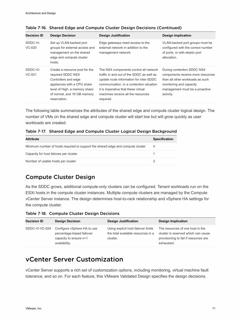
Table 7‑16. Shared Edge and Compute Cluster Design Decisions (Continued)
Decision ID Design Decision Design Justification Design Implication
SDDC-VI-VC-020
Set up VLAN-backed portgroups for external access andmanagement on the sharededge and compute clusterhosts.
Edge gateways need access to theexternal network in addition to themanagement network.
VLAN-backed port groups must beconfigured with the correct numberof ports, or with elastic portallocation.
SDDC-VI-VC-021
Create a resource pool for therequired SDDC NSXControllers and edgeappliances with a CPU sharelevel of High, a memory shareof normal, and 16 GB memoryreservation.
The NSX components control all networktraffic in and out of the SDDC as well asupdate route information for inter-SDDCcommunication. In a contention situationit is imperative that these virtualmachines receive all the resourcesrequired.
During contention SDDC NSXcomponents receive more resourcesthan all other workloads as suchmonitoring and capacitymanagement must be a proactiveactivity.
The following table summarizes the attributes of the shared edge and compute cluster logical design. Thenumber of VMs on the shared edge and compute cluster will start low but will grow quickly as userworkloads are created.
Table 7‑17. Shared Edge and Compute Cluster Logical Design Background
Attribute Specification
Minimum number of hosts required to support the shared edge and compute cluster 4
Capacity for host failures per cluster 1
Number of usable hosts per cluster 3
Compute Cluster DesignAs the SDDC grows, additional compute-only clusters can be configured. Tenant workloads run on theESXi hosts in the compute cluster instances. Multiple compute clusters are managed by the ComputevCenter Server instance. The design determines host-to-rack relationship and vSphere HA settings forthe compute cluster.
Table 7‑18. Compute Cluster Design Decisions
Decision ID Design Decision Design Justification Design Implication
SDDC-VI-VC-024 Configure vSphere HA to usepercentage-based failovercapacity to ensure n+1availability.
Using explicit host failover limitsthe total available resources in acluster.
The resources of one host in thecluster is reserved which can causeprovisioning to fail if resources areexhausted.
vCenter Server CustomizationvCenter Server supports a rich set of customization options, including monitoring, virtual machine faulttolerance, and so on. For each feature, this VMware Validated Design specifies the design decisions.
Architecture and Design
VMware, Inc. 71
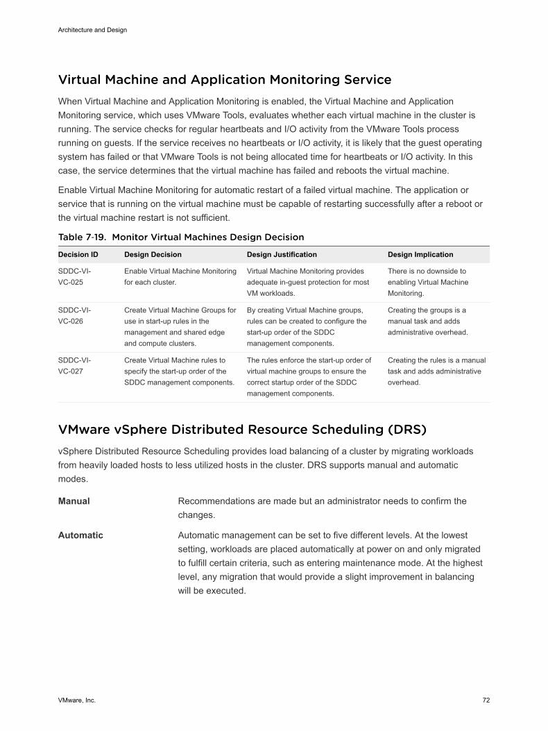
Virtual Machine and Application Monitoring ServiceWhen Virtual Machine and Application Monitoring is enabled, the Virtual Machine and ApplicationMonitoring service, which uses VMware Tools, evaluates whether each virtual machine in the cluster isrunning. The service checks for regular heartbeats and I/O activity from the VMware Tools processrunning on guests. If the service receives no heartbeats or I/O activity, it is likely that the guest operatingsystem has failed or that VMware Tools is not being allocated time for heartbeats or I/O activity. In thiscase, the service determines that the virtual machine has failed and reboots the virtual machine.
Enable Virtual Machine Monitoring for automatic restart of a failed virtual machine. The application orservice that is running on the virtual machine must be capable of restarting successfully after a reboot orthe virtual machine restart is not sufficient.
Table 7‑19. Monitor Virtual Machines Design Decision
Decision ID Design Decision Design Justification Design Implication
SDDC-VI-VC-025
Enable Virtual Machine Monitoringfor each cluster.
Virtual Machine Monitoring providesadequate in-guest protection for mostVM workloads.
There is no downside toenabling Virtual MachineMonitoring.
SDDC-VI-VC-026
Create Virtual Machine Groups foruse in start-up rules in themanagement and shared edgeand compute clusters.
By creating Virtual Machine groups,rules can be created to configure thestart-up order of the SDDCmanagement components.
Creating the groups is amanual task and addsadministrative overhead.
SDDC-VI-VC-027
Create Virtual Machine rules tospecify the start-up order of theSDDC management components.
The rules enforce the start-up order ofvirtual machine groups to ensure thecorrect startup order of the SDDCmanagement components.
Creating the rules is a manualtask and adds administrativeoverhead.
VMware vSphere Distributed Resource Scheduling (DRS)vSphere Distributed Resource Scheduling provides load balancing of a cluster by migrating workloadsfrom heavily loaded hosts to less utilized hosts in the cluster. DRS supports manual and automaticmodes.
Manual Recommendations are made but an administrator needs to confirm thechanges.
Automatic Automatic management can be set to five different levels. At the lowestsetting, workloads are placed automatically at power on and only migratedto fulfill certain criteria, such as entering maintenance mode. At the highestlevel, any migration that would provide a slight improvement in balancingwill be executed.
Architecture and Design
VMware, Inc. 72
Table 7‑20. vSphere Distributed Resource Scheduling Design Decision
Decision ID Design Decision Design Justification Design Implication
SDDC-VI-VC-028 Enable DRS on all clusters andset it to Fully Automated, withthe default setting (medium).
The default settings provide thebest trade-off between loadbalancing and excessive migrationwith vMotion events.
In the event of a vCenter outage,mapping from virtual machines toESXi hosts might be more difficult todetermine.
Enhanced vMotion Compatibility (EVC)EVC works by masking certain features of newer CPUs to allow migration between hosts containing olderCPUs. EVC works only with CPUs from the same manufacturer and there are limits to the versiondifference gaps between the CPU families.
If you set EVC during cluster creation, you can add hosts with newer CPUs at a later date withoutdisruption. You can use EVC for a rolling upgrade of all hardware with zero downtime.
Set EVC to the highest level possible with the current CPUs in use.
Table 7‑21. VMware Enhanced vMotion Compatibility Design Decision
Decision ID Design Decision Design Justification Design Implication
SDDC-VI-VC-029 Enable Enhanced vMotion Compatibilityon all clusters. Set EVC mode to thelowest available setting supported for thehosts in the cluster.
Allows cluster upgradeswithout virtual machinedowntime.
You can enable EVC only ifclusters contain hosts with CPUsfrom the same vendor.
Use of Transport Layer Security (TLS) CertificatesBy default, vSphere 6.5 uses TLS/SSL certificates that are signed by VMCA (VMware CertificateAuthority). These certificates are not trusted by end-user devices or browsers. It is a security best practiceto replace at least all user-facing certificates with certificates that are signed by a third-party or enterpriseCertificate Authority (CA). Certificates for machine-to-machine communication can remain as VMCA-signed certificates.
Table 7‑22. vCenter Server TLS Certificate Design Decision
Decision ID Design Decision Design Justification Design Implication
SDDC-VI-VC-030 Replace the vCenter Server machinecertificate and Platform ServicesController machine certificate with acertificate signed by a 3rd partyPublic Key Infrastructure.
Infrastructure administrators connect toboth vCenter Server and the PlatformServices Controller using a Web browser toperform configuration, management andtroubleshooting activities. Certificatewarnings result with the default certificate.
Replacing and managingcertificates is anoperational overhead.
SDDC-VI-VC-031 Use a SHA-2 or higher algorithmwhen signing certificates.
The SHA-1 algorithm is considered lesssecure and has been deprecated.
Not all certificateauthorities supportSHA-2.
Architecture and Design
VMware, Inc. 73
Virtualization Network DesignA well-designed network helps the organization meet its business goals. It prevents unauthorized access,and provides timely access to business data.
This network virtualization design uses vSphere and VMware NSX for vSphere to implement virtualnetworking.
Virtual Network Design GuidelinesThis VMware Validated Design follows high-level network design guidelines and networking bestpractices.
Design GoalsThe high-level design goals apply regardless of your environment.
n Meet diverse needs. The network must meet the diverse needs of many different entities in anorganization. These entities include applications, services, storage, administrators, and users.
n Reduce costs. Reducing costs is one of the simpler goals to achieve in the vSphere infrastructure.Server consolidation alone reduces network costs by reducing the number of required network portsand NICs, but a more efficient network design is desirable. For example, configuring two 10 GbENICs with VLANs might be more cost effective than configuring a dozen 1 GbE NICs on separatephysical networks.
n Boost performance. You can achieve performance improvement and decrease the time that isrequired to perform maintenance by providing sufficient bandwidth, which reduces contention andlatency.
n Improve availability. A well-designed network improves availability, typically by providing networkredundancy.
n Support security. A well-designed network supports an acceptable level of security through controlledaccess (where required) and isolation (where necessary).
n Enhance infrastructure functionality. You can configure the network to support vSphere features suchas vSphere vMotion, vSphere High Availability, and vSphere Fault Tolerance.
Best PracticesFollow networking best practices throughout your environment.
n Separate network services from one another to achieve greater security and better performance.
n Use Network I/O Control and traffic shaping to guarantee bandwidth to critical virtual machines.During network contention these critical virtual machines will receive a higher percentage of thebandwidth.
n Separate network services on a single vSphere Distributed Switch by attaching them to port groupswith different VLAN IDs.
Architecture and Design
VMware, Inc. 74
n Keep vSphere vMotion traffic on a separate network. When migration with vMotion occurs, thecontents of the guest operating system’s memory is transmitted over the network. You can putvSphere vMotion on a separate network by using a dedicated vSphere vMotion VLAN.
n When using pass-through devices with Linux kernel version 2.6.20 or an earlier guest OS, avoid MSIand MSI-X modes. These modes have significant performance impact.
n For best performance, use VMXNET3 virtual NICs.
n Ensure that physical network adapters that are connected to the same vSphere Standard Switch orvSphere Distributed Switch, are also connected to the same physical network.
Network Segmentation and VLANsSeparating different types of traffic is required to reduce contention and latency. Separate networks arealso required for access security.
High latency on any network can negatively affect performance. Some components are more sensitive tohigh latency than others. For example, reducing latency is important on the IP storage and the vSphereFault Tolerance logging network because latency on these networks can negatively affect theperformance of multiple virtual machines.
Depending on the application or service, high latency on specific virtual machine networks can alsonegatively affect performance. Use information gathered from the current state analysis and frominterviews with key stakeholder and SMEs to determine which workloads and networks are especiallysensitive to high latency.
Virtual NetworksDetermine the number of networks or VLANs that are required depending on the type of traffic.
n vSphere operational traffic.
n Management
n vMotion
n vSAN
n NFS Storage
n VXLAN
n Traffic that supports the organization’s services and applications.
Virtual SwitchesVirtual switches simplify the configuration process by providing one single pane of glass view forperforming virtual network management tasks.
Architecture and Design
VMware, Inc. 75
Virtual Switch Design BackgroundA vSphere Distributed Switch (distributed switch) offers several enhancements over standard virtualswitches.
Centralizedmanagement
Because distributed switches are created and managed centrally on avCenter Server system, they make the switch configuration more consistentacross ESXi hosts. Centralized management saves time, reducesmistakes, and lowers operational costs.
Additional features Distributed switches offer features that are not available on standard virtualswitches. Some of these features can be useful to the applications andservices that are running in the organization’s infrastructure. For example,NetFlow and port mirroring provide monitoring and troubleshootingcapabilities to the virtual infrastructure.
Consider the following caveats for distributed switches.
n Distributed switches are not manageable when vCenter Server is unavailable. vCenter Servertherefore becomes a tier one application.
Health CheckThe health check service helps identify and troubleshoot configuration errors in vSphere distributedswitches.
Health check helps identify the following common configuration errors.
n Mismatched VLAN trunks between an ESXi host and the physical switches it's connected to.
n Mismatched MTU settings between physical network adapters, distributed switches, and physicalswitch ports.
n Mismatched virtual switch teaming policies for the physical switch port-channel settings.
Health check monitors VLAN, MTU, and teaming policies.
VLANs Checks whether the VLAN settings on the distributed switch match thetrunk port configuration on the connected physical switch ports.
MTU For each VLAN, health check determines whether the physical accessswitch port's MTU jumbo frame setting matches the distributed switch MTUsetting.
Teaming policies Health check determines whether the connected access ports of thephysical switch that participate in an EtherChannel are paired withdistributed ports whose teaming policy is IP hash.
Health check is limited to the access switch port to which the ESXi hosts' NICs connects.
Architecture and Design
VMware, Inc. 76
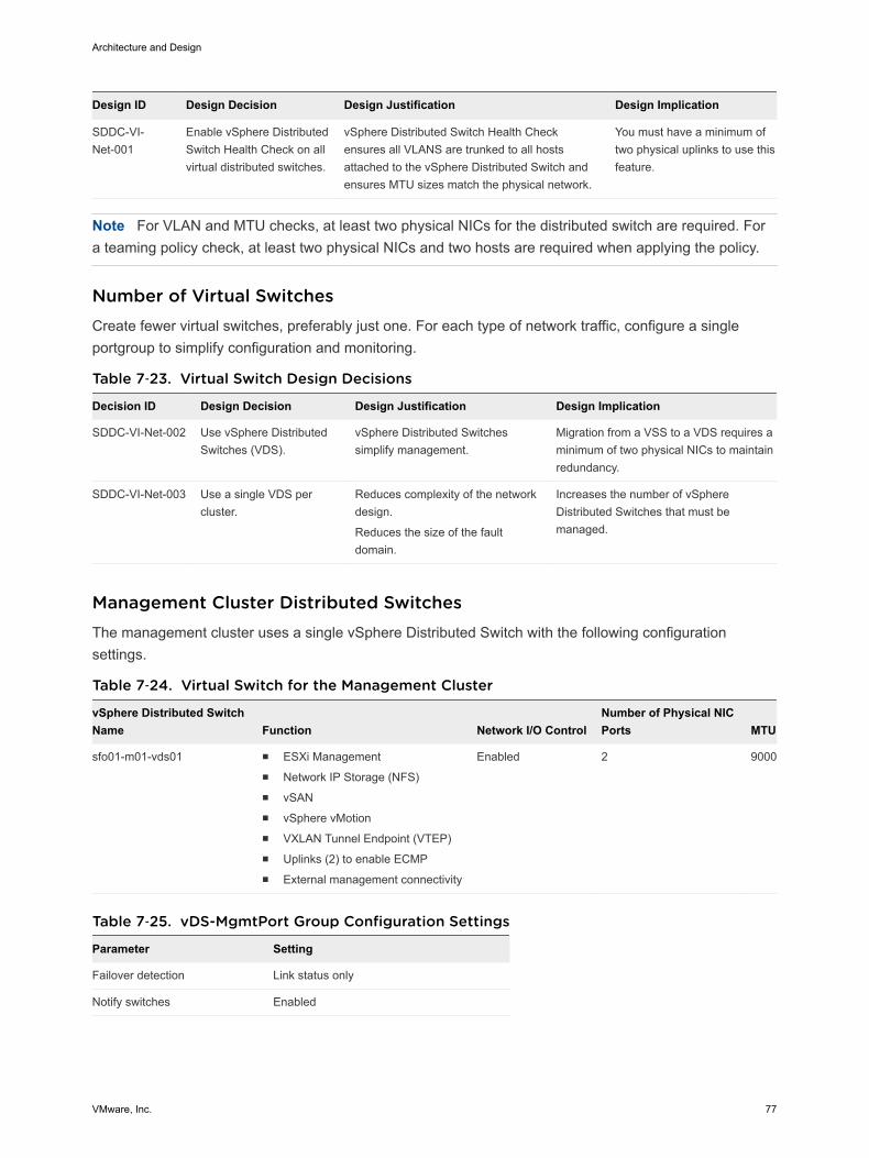
Design ID Design Decision Design Justification Design Implication
SDDC-VI-Net-001
Enable vSphere DistributedSwitch Health Check on allvirtual distributed switches.
vSphere Distributed Switch Health Checkensures all VLANS are trunked to all hostsattached to the vSphere Distributed Switch andensures MTU sizes match the physical network.
You must have a minimum oftwo physical uplinks to use thisfeature.
Note For VLAN and MTU checks, at least two physical NICs for the distributed switch are required. Fora teaming policy check, at least two physical NICs and two hosts are required when applying the policy.
Number of Virtual SwitchesCreate fewer virtual switches, preferably just one. For each type of network traffic, configure a singleportgroup to simplify configuration and monitoring.
Table 7‑23. Virtual Switch Design Decisions
Decision ID Design Decision Design Justification Design Implication
SDDC-VI-Net-002 Use vSphere DistributedSwitches (VDS).
vSphere Distributed Switchessimplify management.
Migration from a VSS to a VDS requires aminimum of two physical NICs to maintainredundancy.
SDDC-VI-Net-003 Use a single VDS percluster.
Reduces complexity of the networkdesign.
Reduces the size of the faultdomain.
Increases the number of vSphereDistributed Switches that must bemanaged.
Management Cluster Distributed SwitchesThe management cluster uses a single vSphere Distributed Switch with the following configurationsettings.
Table 7‑24. Virtual Switch for the Management Cluster
vSphere Distributed SwitchName Function Network I/O Control
Number of Physical NICPorts MTU
sfo01-m01-vds01 n ESXi Managementn Network IP Storage (NFS)n vSANn vSphere vMotionn VXLAN Tunnel Endpoint (VTEP)n Uplinks (2) to enable ECMPn External management connectivity
Enabled 2 9000
Table 7‑25. vDS-MgmtPort Group Configuration Settings
Parameter Setting
Failover detection Link status only
Notify switches Enabled
Architecture and Design
VMware, Inc. 77

Table 7‑25. vDS-MgmtPort Group Configuration Settings(Continued)
Parameter Setting
Failback Yes
Failover order Active uplinks: Uplink1, Uplink2
The following figure illustrates the network switch design.
Note The illustration includes the vSphere Replication VLAN. That VLAN is not needed for a single-region implementation.
Figure 7‑5. Network Switch Design for Management Hosts
nic0 nic1
VLAN VSAN
VLAN ESXi Management
VLAN vMotion
VLAN VTEP (VXLAN)
Sample ESXi Management Host
VLAN vSphere Replication/vSphere Replication NFC
sfo01-m01-vds01
VLAN External Management
VLAN NFS
VLAN Uplink01
VLAN Uplink02
This section expands on the logical network design by providing details on the physical NIC layout andphysical network attributes.
Architecture and Design
VMware, Inc. 78
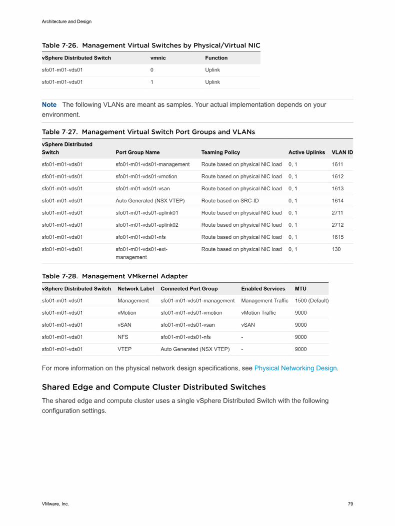
Table 7‑26. Management Virtual Switches by Physical/Virtual NIC
vSphere Distributed Switch vmnic Function
sfo01-m01-vds01 0 Uplink
sfo01-m01-vds01 1 Uplink
Note The following VLANs are meant as samples. Your actual implementation depends on yourenvironment.
Table 7‑27. Management Virtual Switch Port Groups and VLANs
vSphere DistributedSwitch Port Group Name Teaming Policy Active Uplinks VLAN ID
sfo01-m01-vds01 sfo01-m01-vds01-management Route based on physical NIC load 0, 1 1611
sfo01-m01-vds01 sfo01-m01-vds01-vmotion Route based on physical NIC load 0, 1 1612
sfo01-m01-vds01 sfo01-m01-vds01-vsan Route based on physical NIC load 0, 1 1613
sfo01-m01-vds01 Auto Generated (NSX VTEP) Route based on SRC-ID 0, 1 1614
sfo01-m01-vds01 sfo01-m01-vds01-uplink01 Route based on physical NIC load 0, 1 2711
sfo01-m01-vds01 sfo01-m01-vds01-uplink02 Route based on physical NIC load 0, 1 2712
sfo01-m01-vds01 sfo01-m01-vds01-nfs Route based on physical NIC load 0, 1 1615
sfo01-m01-vds01 sfo01-m01-vds01-ext-management
Route based on physical NIC load 0, 1 130
Table 7‑28. Management VMkernel Adapter
vSphere Distributed Switch Network Label Connected Port Group Enabled Services MTU
sfo01-m01-vds01 Management sfo01-m01-vds01-management Management Traffic 1500 (Default)
sfo01-m01-vds01 vMotion sfo01-m01-vds01-vmotion vMotion Traffic 9000
sfo01-m01-vds01 vSAN sfo01-m01-vds01-vsan vSAN 9000
sfo01-m01-vds01 NFS sfo01-m01-vds01-nfs - 9000
sfo01-m01-vds01 VTEP Auto Generated (NSX VTEP) - 9000
For more information on the physical network design specifications, see Physical Networking Design.
Shared Edge and Compute Cluster Distributed SwitchesThe shared edge and compute cluster uses a single vSphere Distributed Switch with the followingconfiguration settings.
Architecture and Design
VMware, Inc. 79
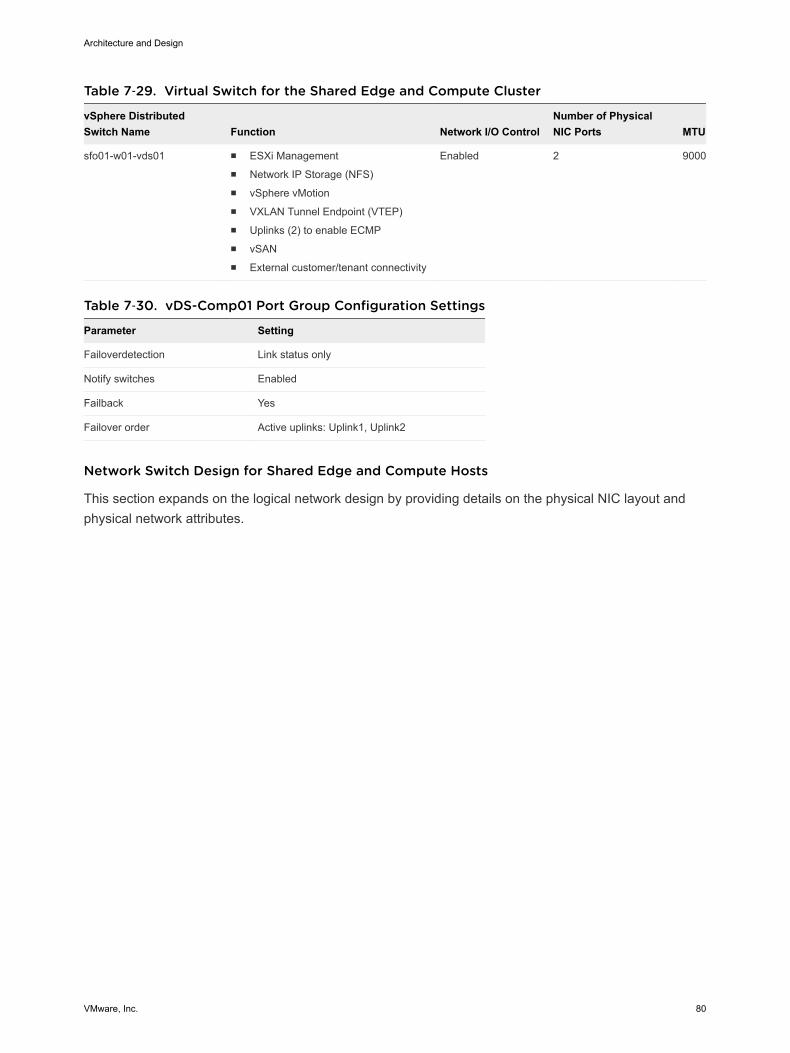
Table 7‑29. Virtual Switch for the Shared Edge and Compute Cluster
vSphere DistributedSwitch Name Function Network I/O Control
Number of PhysicalNIC Ports MTU
sfo01-w01-vds01 n ESXi Managementn Network IP Storage (NFS)n vSphere vMotionn VXLAN Tunnel Endpoint (VTEP)n Uplinks (2) to enable ECMPn vSANn External customer/tenant connectivity
Enabled 2 9000
Table 7‑30. vDS-Comp01 Port Group Configuration Settings
Parameter Setting
Failoverdetection Link status only
Notify switches Enabled
Failback Yes
Failover order Active uplinks: Uplink1, Uplink2
Network Switch Design for Shared Edge and Compute Hosts
This section expands on the logical network design by providing details on the physical NIC layout andphysical network attributes.
Architecture and Design
VMware, Inc. 80
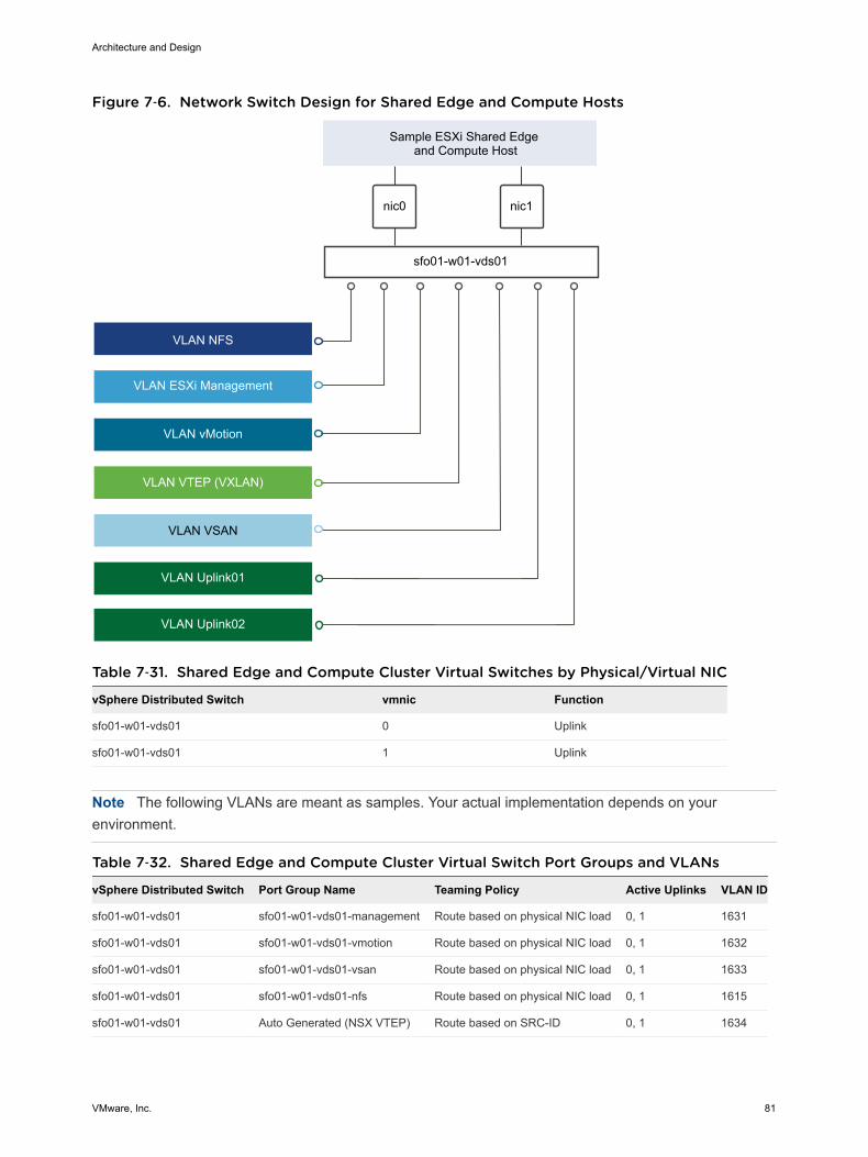
Figure 7‑6. Network Switch Design for Shared Edge and Compute Hosts
nic0 nic1
VLAN VSAN
VLAN ESXi Management
VLAN vMotion
VLAN VTEP (VXLAN)
Sample ESXi Shared Edge and Compute Host
sfo01-w01-vds01
VLAN NFS
VLAN Uplink01
VLAN Uplink02
Table 7‑31. Shared Edge and Compute Cluster Virtual Switches by Physical/Virtual NIC
vSphere Distributed Switch vmnic Function
sfo01-w01-vds01 0 Uplink
sfo01-w01-vds01 1 Uplink
Note The following VLANs are meant as samples. Your actual implementation depends on yourenvironment.
Table 7‑32. Shared Edge and Compute Cluster Virtual Switch Port Groups and VLANs
vSphere Distributed Switch Port Group Name Teaming Policy Active Uplinks VLAN ID
sfo01-w01-vds01 sfo01-w01-vds01-management Route based on physical NIC load 0, 1 1631
sfo01-w01-vds01 sfo01-w01-vds01-vmotion Route based on physical NIC load 0, 1 1632
sfo01-w01-vds01 sfo01-w01-vds01-vsan Route based on physical NIC load 0, 1 1633
sfo01-w01-vds01 sfo01-w01-vds01-nfs Route based on physical NIC load 0, 1 1615
sfo01-w01-vds01 Auto Generated (NSX VTEP) Route based on SRC-ID 0, 1 1634
Architecture and Design
VMware, Inc. 81
Table 7‑32. Shared Edge and Compute Cluster Virtual Switch Port Groups and VLANs(Continued)
vSphere Distributed Switch Port Group Name Teaming Policy Active Uplinks VLAN ID
sfo01-w01-vds01 sfo01-w01-vds01-uplink01 Route based on physical NIC load 0, 1 1635
sfo01-w01-vds01 sfo01-w01-vds01-uplink02 Route based on physical NIC load 0, 1 2713
Table 7‑33. Shared Edge and Compute Cluster VMkernel Adapter
vSphere Distributed Switch Network Label Connected Port Group Enabled Services MTU
sfo01-w01-vds01 Management sfo01-w01-vds01-management Management Traffic 1500 (Default)
sfo01-w01-vds01 vMotion sfo01-w01-vds01-vmotion vMotion Traffic 9000
sfo01-w01-vds01 VSAN sfo01-w01-vds01-vsan VSAN 9000
sfo01-w01-vds01 NFS sfo01-w01-vds01-nfs - 9000
sfo01-w01-vds01 VTEP Auto Generated (NSX VTEP) - 9000
For more information on the physical network design, see Physical Networking Design.
Compute Cluster Distributed SwitchesA compute cluster vSphere Distributed Switch uses the following configuration settings.
Table 7‑34. Virtual Switch for a dedicated Compute Cluster
vSphere Distributed SwitchName Function Network I/O Control
Number of Physical NICPorts MTU
sfo01-w01-vds02 n ESXi Managementn Network IP Storage (NFS)n vSphere vMotionn VXLAN Tunnel Endpoint (VTEP)
Enabled 2 9000
Table 7‑35. vDS-Comp02 Port Group Configuration Settings
Parameter Setting
Failover detection Link status only
Notify switches Enabled
Failback Yes
Failover order Active uplinks: Uplink1, Uplink2
Architecture and Design
VMware, Inc. 82
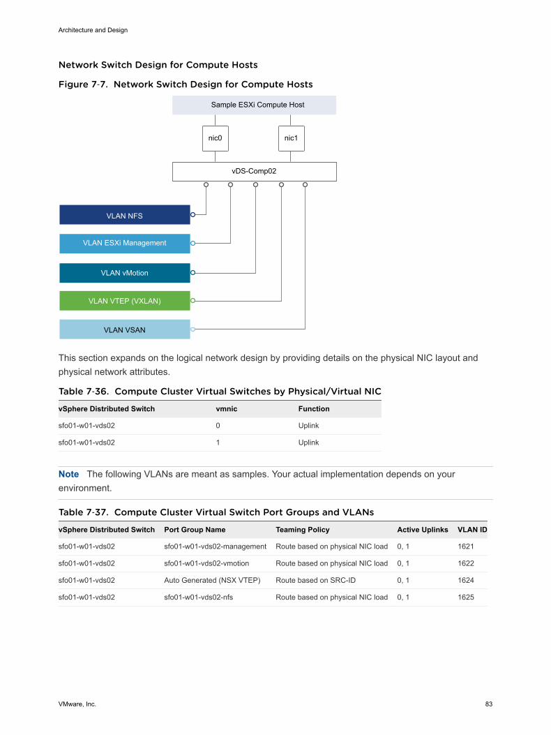
Network Switch Design for Compute Hosts
Figure 7‑7. Network Switch Design for Compute Hosts
nic0 nic1
VLAN VSAN
VLAN ESXi Management
VLAN vMotion
VLAN VTEP (VXLAN)
Sample ESXi Compute Host
VLAN NFS
vDS-Comp02
This section expands on the logical network design by providing details on the physical NIC layout andphysical network attributes.
Table 7‑36. Compute Cluster Virtual Switches by Physical/Virtual NIC
vSphere Distributed Switch vmnic Function
sfo01-w01-vds02 0 Uplink
sfo01-w01-vds02 1 Uplink
Note The following VLANs are meant as samples. Your actual implementation depends on yourenvironment.
Table 7‑37. Compute Cluster Virtual Switch Port Groups and VLANs
vSphere Distributed Switch Port Group Name Teaming Policy Active Uplinks VLAN ID
sfo01-w01-vds02 sfo01-w01-vds02-management Route based on physical NIC load 0, 1 1621
sfo01-w01-vds02 sfo01-w01-vds02-vmotion Route based on physical NIC load 0, 1 1622
sfo01-w01-vds02 Auto Generated (NSX VTEP) Route based on SRC-ID 0, 1 1624
sfo01-w01-vds02 sfo01-w01-vds02-nfs Route based on physical NIC load 0, 1 1625
Architecture and Design
VMware, Inc. 83
Table 7‑38. Compute Cluster VMkernel Adapter
vSphere Distributed Switch Network Label Connected Port Group Enabled Services MTU
sfo01-w01-vds02 Management sfo01-w01-vds02-management Management traffic 1500 (Default)
sfo01-w01-vds02 vMotion sfo01-w01-vds02-vmotion vMotion traffic 9000
sfo01-w01-vds02 NFS sfo01-w01-vds02-nfs - 9000
sfo01-w01-vds02 VTEP Auto Generated (NSX VTEP) - 9000
For more information on the physical network design specifications, see Physical Networking Design.
NIC TeamingYou can use NIC teaming to increase the network bandwidth available in a network path, and to providethe redundancy that supports higher availability.
NIC teaming helps avoid a single point of failure and provides options for load balancing of traffic. Tofurther reduce the risk of a single point of failure, build NIC teams by using ports from multiple NIC andmotherboard interfaces.
Create a single virtual switch with teamed NICs across separate physical switches.
This VMware Validated Design uses an active-active configuration using the route that is based onphysical NIC load algorithm for teaming. In this configuration, idle network cards do not wait for a failureto occur, and they aggregate bandwidth.
Benefits and OverviewNIC teaming helps avoid a single point of failure and provides options for load balancing of traffic. Tofurther reduce the risk of a single point of failure, build NIC teams by using ports from multiple NIC andmotherboard interfaces.
Create a single virtual switch with teamed NICs across separate physical switches.
This VMware Validated Design uses an active-active configuration using the route that is based onphysical NIC load algorithm for teaming. In this configuration, idle network cards do not wait for a failureto occur, and they aggregate bandwidth.
NIC Teaming Design BackgroundFor a predictable level of performance, use multiple network adapters in one of the followingconfigurations.
n An active-passive configuration that uses explicit failover when connected to two separate switches.
n An active-active configuration in which two or more physical NICs in the server are assigned theactive role.
This validated design uses an active-active configuration.
Architecture and Design
VMware, Inc. 84
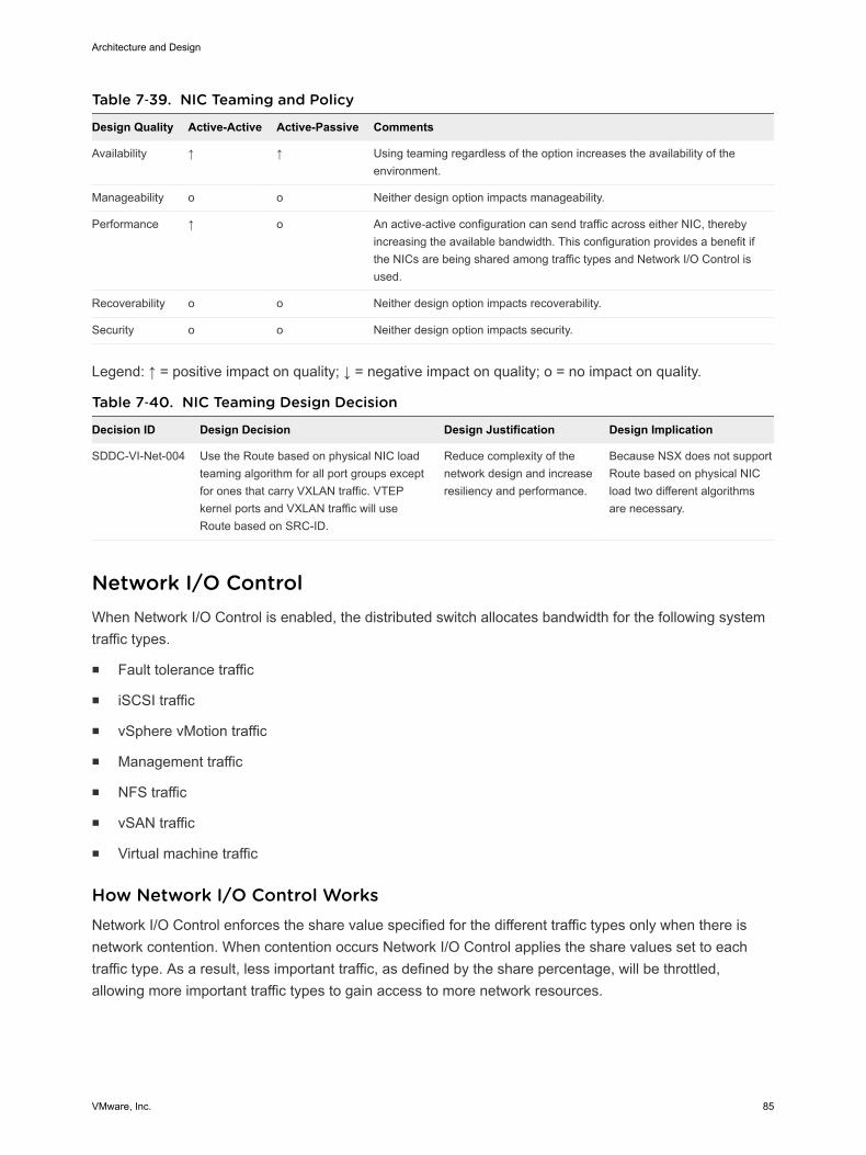
Table 7‑39. NIC Teaming and Policy
Design Quality Active-Active Active-Passive Comments
Availability ↑ ↑ Using teaming regardless of the option increases the availability of theenvironment.
Manageability o o Neither design option impacts manageability.
Performance ↑ o An active-active configuration can send traffic across either NIC, therebyincreasing the available bandwidth. This configuration provides a benefit ifthe NICs are being shared among traffic types and Network I/O Control isused.
Recoverability o o Neither design option impacts recoverability.
Security o o Neither design option impacts security.
Legend: ↑ = positive impact on quality; ↓ = negative impact on quality; o = no impact on quality.
Table 7‑40. NIC Teaming Design Decision
Decision ID Design Decision Design Justification Design Implication
SDDC-VI-Net-004 Use the Route based on physical NIC loadteaming algorithm for all port groups exceptfor ones that carry VXLAN traffic. VTEPkernel ports and VXLAN traffic will useRoute based on SRC-ID.
Reduce complexity of thenetwork design and increaseresiliency and performance.
Because NSX does not supportRoute based on physical NICload two different algorithmsare necessary.
Network I/O ControlWhen Network I/O Control is enabled, the distributed switch allocates bandwidth for the following systemtraffic types.
n Fault tolerance traffic
n iSCSI traffic
n vSphere vMotion traffic
n Management traffic
n NFS traffic
n vSAN traffic
n Virtual machine traffic
How Network I/O Control WorksNetwork I/O Control enforces the share value specified for the different traffic types only when there isnetwork contention. When contention occurs Network I/O Control applies the share values set to eachtraffic type. As a result, less important traffic, as defined by the share percentage, will be throttled,allowing more important traffic types to gain access to more network resources.
Architecture and Design
VMware, Inc. 85
Network I/O Control also allows the reservation of bandwidth for system traffic based on the capacity ofthe physical adapters on a host, and enables fine-grained resource control at the virtual machine networkadapter level. Resource control is similar to the model for vCenter CPU and memory reservations.
Network I/O Control HeuristicsThe following heuristics can help with design decisions.
Shares vs. Limits When you use bandwidth allocation, consider using shares instead of limits.Limits impose hard limits on the amount of bandwidth used by a traffic floweven when network bandwidth is available.
Limits on CertainResource Pools
Consider imposing limits on a given resource pool. For example, if you puta limit on vSphere vMotion traffic, you can benefit in situations wheremultiple vSphere vMotion data transfers, initiated on different hosts at thesame time, result in oversubscription at the physical network level. Bylimiting the available bandwidth for vSphere vMotion at the ESXi host level,you can prevent performance degradation for other traffic.
Teaming Policy When you use Network I/O Control, use Route based on physical NIC loadteaming as a distributed switch teaming policy to maximize the networkingcapacity utilization. With load-based teaming, traffic might move amonguplinks, and reordering of packets at the receiver can result occasionally.
Traffic Shaping Use distributed port groups to apply configuration policies to different traffictypes. Traffic shaping can help in situations where multiple vSpherevMotion migrations initiated on different hosts converge on the samedestination host. The actual limit and reservation also depend on the trafficshaping policy for the distributed port group where the adapter is connectedto.
Network I/O Control Design DecisionsBased on the heuristics, this design has the following decisions.
Table 7‑41. Network I/O Control Design Decisions
Decision ID Design Decision Design Justification Design Implication
SDDC-VI-NET-005
Enable Network I/O Control onall distributed switches.
Increase resiliency and performance of thenetwork.
If configuredincorrectly Network I/OControl could impactnetwork performancefor critical traffic types.
SDDC-VI-NET-006
Set the share value for vMotiontraffic to Low.
During times of contention vMotion traffic is not asimportant as virtual machine or storage traffic.
During times ofnetwork contentionvMotion's will takelonger than usual tocomplete.
Architecture and Design
VMware, Inc. 86
Table 7‑41. Network I/O Control Design Decisions (Continued)
Decision ID Design Decision Design Justification Design Implication
SDDC-VI-NET-008
Set the share value for vSANto High.
During times of contention vSAN traffic needsguaranteed bandwidth so virtual machineperformance does not suffer.
None.
SDDC-VI-NET-009
Set the share value forManagement to Normal.
By keeping the default setting of Normalmanagement traffic is prioritized higher thanvMotion but lower then vSAN traffic. Managementtraffic is important as it ensures the hosts can stillbe managed during times of network contention.
None.
SDDC-VI-NET-010
Set the share value for NFSTraffic to Low.
Because NFS is used for secondary storage suchas vRealize Log Insight archives, it is not asimportant as vSAN traffic.
None
SDDC-VI-NET-012
Set the share value for virtualmachines to High.
Virtual machines are the most important asset inthe SDDC. Leaving the default setting of Highensures that they will always have access to thenetwork resources they need.
None.
SDDC-VI-NET-013
Set the share value for FaultTolerance to Low.
Fault Tolerance is not used in this design thereforeit can be set to the lowest priority.
None.
SDDC-VI-NET-014
Set the share value for iSCSItraffic to Low.
iSCSI is not used in this design therefore it can beset to the lowest priority.
None.
VXLANVXLAN provides the capability to create isolated, multi-tenant broadcast domains across data centerfabrics, and enables customers to create elastic, logical networks that span physical network boundaries.
The first step in creating these logical networks is to abstract and pool the networking resources. Just asvSphere abstracts compute capacity from the server hardware to create virtual pools of resources thatcan be consumed as a service, vSphere Distributed Switch and VXLAN abstract the network into ageneralized pool of network capacity and separate the consumption of these services from the underlyingphysical infrastructure. A network capacity pool can span physical boundaries, optimizing computeresource utilization across clusters, pods, and geographically-separated data centers. The unified pool ofnetwork capacity can then be optimally segmented into logical networks that are directly attached tospecific applications.
VXLAN works by creating Layer 2 logical networks that are encapsulated in standard Layer 3 IP packets.A Segment ID in every frame differentiates the VXLAN logical networks from each other without any needfor VLAN tags. As a result, large numbers of isolated Layer 2 VXLAN networks can coexist on a commonLayer 3 infrastructure.
In the vSphere architecture, the encapsulation is performed between the virtual NIC of the guest VM andthe logical port on the virtual switch, making VXLAN transparent to both the guest virtual machines andthe underlying Layer 3 network. Gateway services between VXLAN and non-VXLAN hosts (for example,a physical server or the Internet router) are performed by the NSX Edge Services Gateway appliance.The Edge gateway translates VXLAN segment IDs to VLAN IDs, so that non-VXLAN hosts cancommunicate with virtual machines on a VXLAN network.
Architecture and Design
VMware, Inc. 87
The shared edge and compute cluster hosts all NSX Edge instances and all Universal Distributed LogicalRouter instances that are connect to the Internet or to corporate VLANs, so that the network administratorcan manage the environment in a more secure and centralized way.
Table 7‑42. VXLAN Design Decisions
Decision ID Design Decision Design Justification Design Implication
SDDC-VI-Net-015
Use NSX for vSphere to introduceVXLANs for the use of virtual applicationnetworks and tenants networks.
Simplify the networkconfiguration for each tenant viacentralized virtual networkmanagement.
Requires additional compute andstorage resources to deploy NSXcomponents.
Additional training may beneeded on NSX.
SDDC-VI-Net-016
Use VXLAN along with NSX Edgegateways, the Universal DistributedLogical Router (UDLR) and DistributedLogical Router (DLR) to providecustomer/tenant network capabilities.
Create isolated, multi-tenantbroadcast domains across datacenter fabrics to create elastic,logical networks that spanphysical network boundaries.
Transport networks and MTUgreater than 1600 bytes has to beconfigured in the reachabilityradius.
SDDC-VI-Net-017
Use VXLAN along with NSX Edgegateways and the Universal DistributedLogical Router (UDLR) to providemanagement application networkcapabilities.
Leverage benefits of networkvirtualization in themanagement pod.
Requires installation andconfiguration of a NSX forvSphere instance in themanagement pod.
vMotion TCP/IP StackUse the vMotion TCP/IP stack to isolate traffic for vMotion and to assign a dedicated default gateway forvMotion traffic.
By using a separate TCP/IP stack, you can manage vMotion and cold migration traffic according to thetopology of the network, and as required for your organization.
n Route the traffic for the migration of virtual machines that are powered on or powered off by using adefault gateway that is different from the gateway assigned to the default stack on the host.
n Assign a separate set of buffers and sockets.
n Avoid routing table conflicts that might otherwise appear when many features are using a commonTCP/IP stack.
n Isolate traffic to improve security.
Decision ID Design Decision Design Justification Design Implication
SDDC-VI-Net-018
Use the vMotionTCP/IP stack forvMotion traffic.
By leveraging the vMotion TCP/IP stack,vMotion traffic can utilize a default gatewayon its own subnet, allowing for vMotiontraffic to go over Layer 3 networks.
The vMotion TCP/IP stack is not availablein the vDS VMkernel creation wizard, andas such the VMkernal adapter must becreated directly on a host.
Architecture and Design
VMware, Inc. 88
NSX DesignThis design implements software-defined networking by using VMware NSX™ for vSphere®. By usingNSX for vSphere, virtualization delivers for networking what it has already delivered for compute andstorage.
In much the same way that server virtualization programmatically creates, snapshots, deletes, andrestores software-based virtual machines (VMs), NSX network virtualization programmatically creates,snapshots, deletes, and restores software-based virtual networks. The result is a transformative approachto networking that not only enables data center managers to achieve orders of magnitude better agilityand economics, but also supports a vastly simplified operational model for the underlying physicalnetwork. NSX for vSphere is a nondisruptive solution because it can be deployed on any IP network,including existing traditional networking models and next-generation fabric architectures, from any vendor.
When administrators provision workloads, network management is one of the most time-consuming tasks.Most of the time spent provisioning networks is consumed configuring individual components in thephysical infrastructure and verifying that network changes do not affect other devices that are using thesame networking infrastructure.
The need to pre-provision and configure networks is a major constraint to cloud deployments wherespeed, agility, and flexibility are critical requirements. Pre-provisioned physical networks can allow for therapid creation of virtual networks and faster deployment times of workloads utilizing the virtual network.As long as the physical network that you need is already available on the host where the workload is tobe deployed, this works well. However, if the network is not available on a given host, you must find ahost with the available network and spare capacity to run your workload in your environment.
To get around this bottleneck requires a decoupling of virtual networks from their physical counterparts.This, in turn, requires that you can programmatically recreate all physical networking attributes that arerequired by workloads in the virtualized environment. Because network virtualization supports the creationof virtual networks without modification of the physical network infrastructure, it allows more rapid networkprovisioning.
NSX for vSphere DesignEach NSX instance is tied to a vCenter Server instance. The design decision to deploy two vCenterServer instances per region(SDDC-VI-VC-001) requires deployment of two separate NSX instances perregion.
Architecture and Design
VMware, Inc. 89
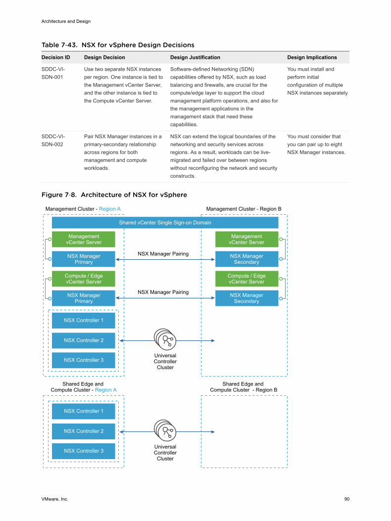
Table 7‑43. NSX for vSphere Design Decisions
Decision ID Design Decision Design Justification Design Implications
SDDC-VI-SDN-001
Use two separate NSX instancesper region. One instance is tied tothe Management vCenter Server,and the other instance is tied tothe Compute vCenter Server.
Software-defined Networking (SDN)capabilities offered by NSX, such as loadbalancing and firewalls, are crucial for thecompute/edge layer to support the cloudmanagement platform operations, and also forthe management applications in themanagement stack that need thesecapabilities.
You must install andperform initialconfiguration of multipleNSX instances separately.
SDDC-VI-SDN-002
Pair NSX Manager instances in aprimary-secondary relationshipacross regions for bothmanagement and computeworkloads.
NSX can extend the logical boundaries of thenetworking and security services acrossregions. As a result, workloads can be live-migrated and failed over between regionswithout reconfiguring the network and securityconstructs.
You must consider thatyou can pair up to eightNSX Manager instances.
Figure 7‑8. Architecture of NSX for vSphere
UniversalController
Cluster
UniversalController
Cluster
Management Cluster - Region A
Shared Edge and Compute Cluster - Region A
Shared Edge and Compute Cluster - Region B
Shared vCenter Single Sign-on Domain
NSX Manager Pairing
NSX Manager Pairing
ManagementvCenter Server
NSX ManagerPrimary
NSX ManagerPrimary
NSX Controller 1
NSX Controller 2
NSX Controller 3
NSX Controller 1
NSX Controller 2
NSX Controller 3
Compute / EdgevCenter Server
Management Cluster - Region B
ManagementvCenter Server
NSX ManagerSecondary
NSX ManagerSecondary
Compute / EdgevCenter Server
Architecture and Design
VMware, Inc. 90
NSX ComponentsThe following sections describe the components in the solution and how they are relevant to the networkvirtualization design.
Consumption LayerIf the design is expanded, a cloud management platform such as vRealize Automation can consume NSXfor vSphere by using the NSX REST API, the vSphere Web Client, or both.
APINSX for vSphere offers a powerful management interface through its REST API.
n A client can read an object by making an HTTP GET request to the object’s resource URL.
n A client can write (create or modify) an object with an HTTP PUT or POST request that includes anew or changed XML document for the object.
n A client can delete an object with an HTTP DELETE request.
Note Some of the use case designs do not include a cloud platform.
vSphere Web ClientThe NSX Manager component provides a networking and security plug-in in the vSphere Web Client. Thisplug-in provides an interface to consuming virtualized networking from the NSX Manager for users thathave sufficient privileges.
Table 7‑44. Consumption Method Design Decisions
Decision ID Design Decision Design Justification Design Implications
SDDC-VI-SDN-003
For the shared edge and compute clusterNSX instance, administrators can useboth the vSphere Web Client and theNSX REST API.
The vSphere Web Client consumes NSXfor vSphere resources through theNetwork and Security plug-in. The NSXREST API offers the potential ofscripting repeating actions andoperations.
None.
SDDC-VI-SDN-004
For the management cluster NSXinstance, consumption is only by providerstaff via the vSphere Web Client and theAPI.
Ensures that infrastructure componentsare not modified by tenants and/or non-provider staff.
Tenants do not haveaccess to themanagement stackworkloads.
NSX ManagerNSX Manager provides the centralized management plane for NSX for vSphere and has a one-to-onemapping to vCenter Server workloads.
Architecture and Design
VMware, Inc. 91
NSX Manager performs the following functions.
n Provides the single point of configuration and the REST API entry-points for NSX in a vSphereenvironment.
n Deploys NSX Controller clusters, Edge distributed routers, and Edge service gateways in the form ofOVF appliances, guest introspection services, and so on.
n Prepares ESXi hosts for NSX by installing VXLAN, distributed routing and firewall kernel modules,and the User World Agent (UWA).
n Communicates with NSX Controller clusters over REST and with hosts over the RabbitMQ messagebus. This internal message bus is specific to NSX for vSphere and does not require setup ofadditional services.
n Generates certificates for the NSX Controller instances and ESXi hosts to secure control planecommunications with mutual authentication.
NSX ControllerAn NSX Controller performs the following functions.
n Provides the control plane to distribute VXLAN and logical routing information to ESXi hosts.
n Includes nodes that are clustered for scale-out and high availability.
n Slices network information across cluster nodes for redundancy.
n Removes requirement of VXLAN Layer 3 multicast in the physical network.
n Provides ARP suppression of broadcast traffic in VXLAN networks.
NSX control plane communication occurs over the management network.
Table 7‑45. NSX Controller Design Decision
Decision ID Design Decision Design Justification Design Implications
SDDC-VI-SDN-005
Deploy NSX Controller instances inUniversal Cluster mode with threemembers to provide highavailability and scale. Provisionthese three nodes through theprimary NSX Manager instance.
The high availability of NSXController reduces thedowntime period in case offailure of one physical host.
The secondary NSX Manager will nothave active controllers but willautomatically import the configurationof the Universal Controllers that arecreated in the primary NSX Manager
NSX Virtual SwitchThe NSX data plane consists of the NSX virtual switch. This virtual switch is based on the vSphereDistributed Switch (VDS)with additional components to enable rich services. The add-on NSXcomponents include kernel modules (VIBs) which run within the hypervisor kernel and provide servicessuch as distributed logical router (DLR) and distributed firewall (DFW), and VXLAN capabilities.
Architecture and Design
VMware, Inc. 92
The NSX virtual switch abstracts the physical network and provides access-level switching in thehypervisor. It is central to network virtualization because it enables logical networks that are independentof physical constructs such as VLAN. Using an NSX virtual switch includes several benefits.
n Supports overlay networking and centralized network configuration. Overlay networking enables thefollowing capabilities.
n Facilitates massive scale of hypervisors.
n Because the NSX virtual switch is based on VDS, it provides a comprehensive toolkit for trafficmanagement, monitoring, and troubleshooting within a virtual network through features such as portmirroring, NetFlow/IPFIX, configuration backup and restore, network health check, QoS, and more.
Logical SwitchingNSX logical switches create logically abstracted segments to which tenant virtual machines can beconnected. A single logical switch is mapped to a unique VXLAN segment and is distributed across theESXi hypervisors within a transport zone. The logical switch allows line-rate switching in the hypervisorwithout the constraints of VLAN sprawl or spanning tree issues.
Distributed Logical RouterThe NSX distributed logical router (DLR) is optimized for forwarding in the virtualized space, that is,forwarding between VMs on VXLAN- or VLAN-backed port groups. DLR has the following characteristics.
n High performance, low overhead first hop routing
n Scales with number of hosts
n Up to 1,000 Logical Interfaces (LIFs) on each DLR
Distributed LogicalRouter Control Virtual MachineThe distributed logical router control virtual machine is the control plane component of the routingprocess, providing communication between NSX Manager and the NSX Controller cluster through theUser World Agent (UWA). NSX Manager sends logical interface information to the control virtual machineand the NSX Controller cluster, and the control virtual machine sends routing updates to the NSXController cluster.
User World AgentThe User World Agent (UWA) is a TCP (SSL) client that facilitates communication between the ESXihosts and the NSX Controller instances as well as the retrieval of information from the NSX Manager viainteraction with the message bus agent.
Architecture and Design
VMware, Inc. 93
VXLAN Tunnel EndpointVXLAN Tunnel Endpoints (VTEPs) are instantiated within the vSphere Distributed Switch to which theESXi hosts that are prepared for NSX for vSphere are connected. VTEPs are responsible forencapsulating VXLAN traffic as frames in UDP packets and for the corresponding decapsulation. VTEPstake the form of one or more VMkernel ports with IP addresses and are used both to exchange packetswith other VTEPs and to join IP multicast groups via Internet Group Membership Protocol (IGMP). If youuse multiple VTEPs, then you must select a teaming method.
Edge Services GatewayThe NSX Edge services gateways (ESGs) primary function is north/south communication, but it alsooffers support for Layer 2, Layer 3, perimeter firewall, load balancing and other services such as SSL-VPN and DHCP-relay.
Distributed FirewallNSX includes a distributed kernel-level firewall known as the distributed firewall. Security enforcement isdone at the kernel and VM network adapter level. The security enforcement implementation enablesfirewall rule enforcement in a highly scalable manner without creating bottlenecks on physical appliances.The distributed firewall has minimal CPU overhead and can perform at line rate.
The flow monitoring feature of the distributed firewall displays network activity between virtual machinesat the application protocol level. This information can be used to audit network traffic, define and refinefirewall policies, and identify botnets.
Logical Load BalancerThe NSX logical load balancer provides load balancing services up to Layer 7, allowing distribution oftraffic across multiple servers to achieve optimal resource utilization and availability. The logical loadbalancer is a service provided by the NSX Edge service gateway.
NSX for vSphere RequirementsNSX for vSphere requirements impact both physical and virtual networks.
Physical Network RequirementsPhysical requirements determine the MTU size for networks that carry VLAN traffic, dynamic routingsupport, type synchronization through an NTP server, and forward and reverse DNS resolution.
Architecture and Design
VMware, Inc. 94
Requirement Comments
Any network that carries VXLAN traffic must havean MTU size of 1600 or greater.
VXLAN packets cannot be fragmented. The MTU size must be large enoughto support extra encapsulation overhead.
This design uses jumbo frames, MTU size of 9000, for VXLAN traffic.
For the hybrid replication mode, Internet GroupManagement Protocol (IGMP) snooping must beenabled on the Layer 2 switches to which ESXihosts that participate in VXLAN are attached.IGMP querier must be enabled on the connectedrouter or Layer 3 switch.
IGMP snooping on Layer 2 switches is a requirement of the hybrid replicationmode. Hybrid replication mode is the recommended replication mode forbroadcast, unknown unicast, and multicast (BUM) traffic when deploying intoan environment with large scale-out potential. The traditional requirement forProtocol Independent Multicast (PIM) is removed.
Dynamic routing support on the upstream Layer 3data center switches must be enabled.
Enable a dynamic routing protocol supported by NSX on the upstream datacenter switches to establish dynamic routing adjacency with the ESGs.
NTP server must be available. The NSX Manager requires NTP settings that synchronize it with the rest ofthe vSphere environment. Drift can cause problems with authentication. TheNSX Manager must be in sync with the vCenter Single Sign-On service on thePlatform Services Controller.
Forward and reverse DNS resolution for allmanagement VMs must be established.
The NSX Controller nodes do not require DNS entries.
NSX Component SpecificationsThe following table lists the components involved in the NSX for vSphere solution and the requirementsfor installing and running them. The compute and storage requirements have been taken into accountwhen sizing resources to support the NSX for vSphere solution.
Note NSX ESG sizing can vary with tenant requirements, so all options are listed.
VM vCPU Memory Storage Quantity per Stack Instance
NSX Manager 4 16 GB 60 GB 1
NSX Controller 4 4 GB 20 GB 3
NSX ESG 1 (Compact)
2 (Large)
4 (Quad Large)
6 (X-Large)
512 MB (Compact)
1 GB (Large)
1 GB (Quad Large)
8 GB (X-Large)
512 MB
512 MB
512 MB
4.5 GB (X-Large)
(+4 GB with swap)
Optional component. Deployment of the NSXESG varies per use case.
DLR control VM 1 512 MB 512 MB Optional component. Varies with use case.Typically 2 per HA pair.
Guest introspection 2 1 GB 4 GB Optional component. 1 per ESXi host.
NSX data security 1 512 MB 6 GB Optional component.1 per ESXi host.
NSX Edge Service Gateway SizingThe Quad Large model is suitable for high performance firewall abilities and the X-Large is suitable forboth high performance load balancing and routing.
Architecture and Design
VMware, Inc. 95
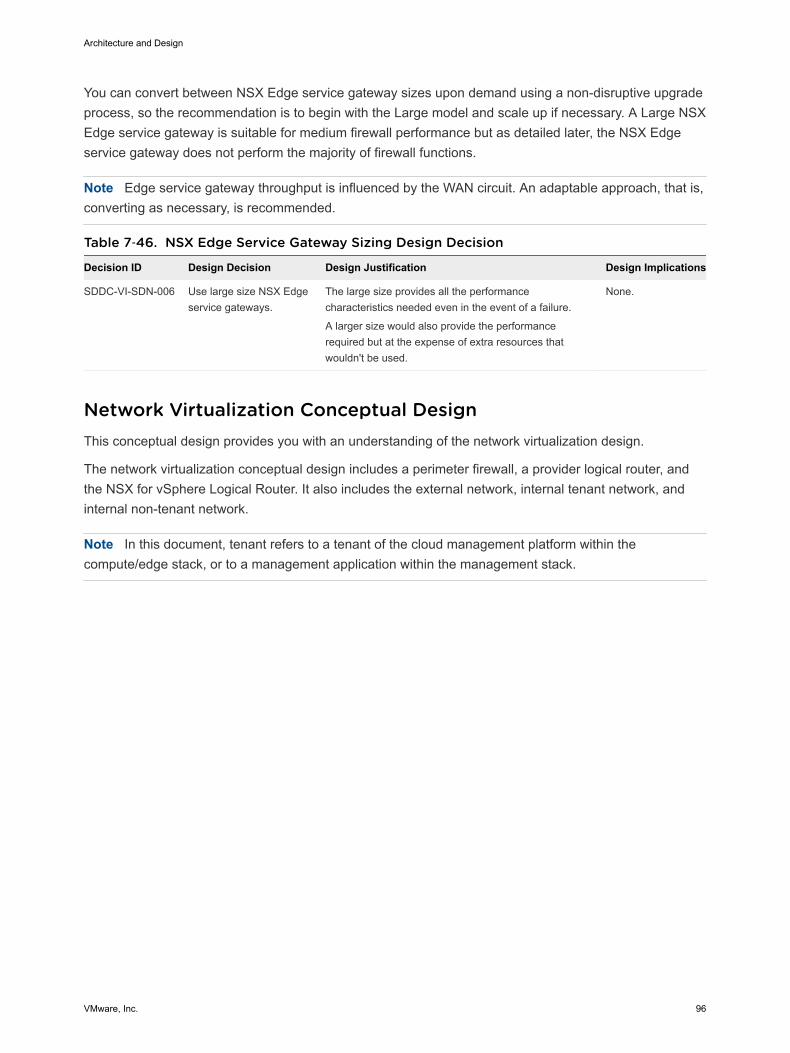
You can convert between NSX Edge service gateway sizes upon demand using a non-disruptive upgradeprocess, so the recommendation is to begin with the Large model and scale up if necessary. A Large NSXEdge service gateway is suitable for medium firewall performance but as detailed later, the NSX Edgeservice gateway does not perform the majority of firewall functions.
Note Edge service gateway throughput is influenced by the WAN circuit. An adaptable approach, that is,converting as necessary, is recommended.
Table 7‑46. NSX Edge Service Gateway Sizing Design Decision
Decision ID Design Decision Design Justification Design Implications
SDDC-VI-SDN-006 Use large size NSX Edgeservice gateways.
The large size provides all the performancecharacteristics needed even in the event of a failure.
A larger size would also provide the performancerequired but at the expense of extra resources thatwouldn't be used.
None.
Network Virtualization Conceptual DesignThis conceptual design provides you with an understanding of the network virtualization design.
The network virtualization conceptual design includes a perimeter firewall, a provider logical router, andthe NSX for vSphere Logical Router. It also includes the external network, internal tenant network, andinternal non-tenant network.
Note In this document, tenant refers to a tenant of the cloud management platform within thecompute/edge stack, or to a management application within the management stack.
Architecture and Design
VMware, Inc. 96
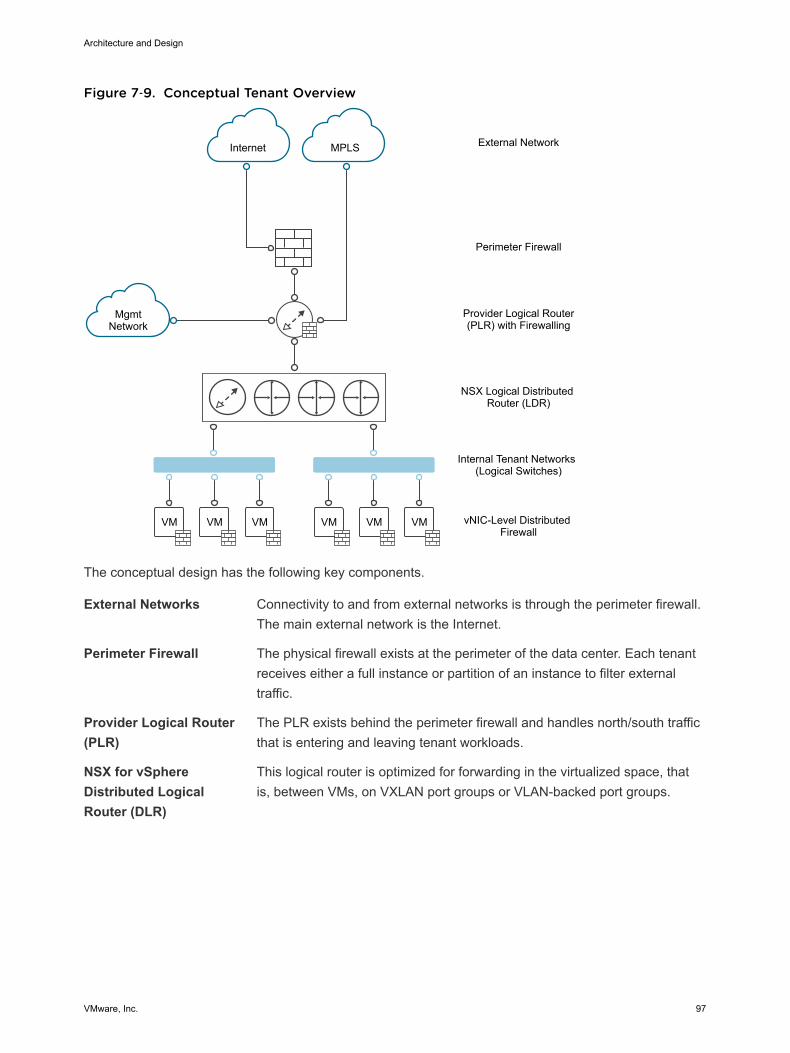
Figure 7‑9. Conceptual Tenant Overview
VM VMVM VM VMVM
Internet MPLS
MgmtNetwork
External Network
Perimeter Firewall
Provider Logical Router(PLR) with Firewalling
NSX Logical Distributed Router (LDR)
Internal Tenant Networks (Logical Switches)
vNIC-Level Distributed Firewall
The conceptual design has the following key components.
External Networks Connectivity to and from external networks is through the perimeter firewall.The main external network is the Internet.
Perimeter Firewall The physical firewall exists at the perimeter of the data center. Each tenantreceives either a full instance or partition of an instance to filter externaltraffic.
Provider Logical Router(PLR)
The PLR exists behind the perimeter firewall and handles north/south trafficthat is entering and leaving tenant workloads.
NSX for vSphereDistributed LogicalRouter (DLR)
This logical router is optimized for forwarding in the virtualized space, thatis, between VMs, on VXLAN port groups or VLAN-backed port groups.
Architecture and Design
VMware, Inc. 97
Internal Non-TenantNetwork
A single management network, which sits behind the perimeter firewall butnot behind the PLR. Enables customers to manage the tenantenvironments.
Internal TenantNetworks
Connectivity for the main tenant workload. These networks are connectedto a DLR, which sits behind the PLR. These networks take the form ofVXLAN-based NSX for vSphere logical switches. Tenant virtual machineworkloads will be directly attached to these networks.
Cluster Design for NSX for vSphereFollowing the vSphere design, the NSX for vSphere design consists of a management stack and acompute/edge stack in each region.
Management StackIn the management stack, the underlying hosts are prepared for NSX for vSphere. The managementstack has these components.
n NSX Manager instances for both stacks (management stack and compute/edge stack)
n NSX Controller cluster for the management stack
n NSX ESG and DLR control VMs for the management stack
Compute/Edge StackIn the compute/edge stack, the underlying hosts are prepared for NSX for vSphere. The compute/edgestack has these components.
n NSX Controller cluster for the compute stack.
n All NSX Edge service gateways and DLR control VMs of the compute stack that are dedicated tohandling the north/south traffic in the data center. A shared edge and compute stack helps preventVLAN sprawl because any external VLANs need only be trunked to the hosts in this cluster.
Architecture and Design
VMware, Inc. 98
Table 7‑47. vSphere Cluster Design Decisions
Decision ID Design Decision Design Justification Design Implications
SDDC-VI-SDN-007
For the compute stack, donot use a dedicated edgecluster.
Simplifies configuration andminimizes the number of hostsrequired for initial deployment.
The NSX Controller instances, NSX Edgeservices gateways, and DLR control VMs ofthe compute stack are deployed in theshared edge and compute cluster.
The shared nature of the cluster will requirethe cluster to be scaled out as computeworkloads are added so as to not impactnetwork performance.
SDDC-VI-SDN-008
For the management stack,do not use a dedicated edgecluster.
The number of supportedmanagement applications doesnot justify the cost of a dedicatededge cluster in the managementstack.
The NSX Controller instances, NSX Edgeservice gateways, and DLR control VMs ofthe management stack are deployed in themanagement cluster.
SDDC-VI-SDN-009
Apply vSphere DistributedResource Scheduler (DRS)anti-affinity rules to the NSXcomponents in both stacks.
Using DRS prevents controllersfrom running on the same ESXihost and thereby risking theirhigh availability capability.
Additional configuration is required to set upanti-affinity rules.
The logical design of NSX considers the vCenter Server clusters and define the place where each NSXcomponent runs.
Architecture and Design
VMware, Inc. 99
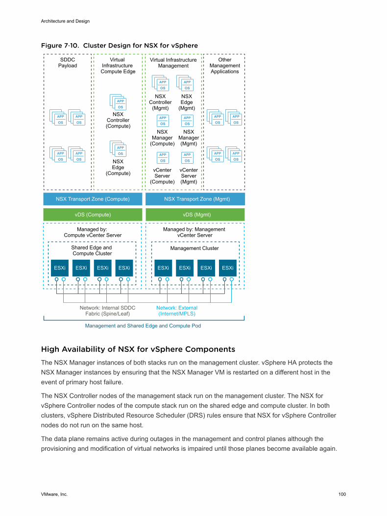
Figure 7‑10. Cluster Design for NSX for vSphere
APP
OSAPP
OS
APP
OSAPP
OS
APP
OSAPP
OS
APP
OSAPP
OS
APP
OS
APP
OS
APP
OSAPP
OS
ESXi ESXi
APP
OSAPP
OS
APP
OSAPP
OS
Virtual InfrastructureManagement
NSXController
(Mgmt)
OtherManagementApplications
NSXEdge
(Mgmt)
NSXManager(Mgmt)
NSXManager
(Compute)
NSXEdge
(Compute)
NSXController(Compute)
ESXi ESXi ESXi ESXi ESXi ESXi
SDDCPayload
Virtual Infrastructure Compute Edge
NSX Transport Zone (Compute)
vDS (Compute) vDS (Mgmt)
NSX Transport Zone (Mgmt)
Shared Edge and Compute Cluster
Management Cluster
Managed by: Compute vCenter Server
Managed by: Management vCenter Server
Network: External(Internet/MPLS)
Network: Internal SDDCFabric (Spine/Leaf)
Management and Shared Edge and Compute Pod
vCenterServer(Mgmt)
vCenterServer
(Compute)
High Availability of NSX for vSphere ComponentsThe NSX Manager instances of both stacks run on the management cluster. vSphere HA protects theNSX Manager instances by ensuring that the NSX Manager VM is restarted on a different host in theevent of primary host failure.
The NSX Controller nodes of the management stack run on the management cluster. The NSX forvSphere Controller nodes of the compute stack run on the shared edge and compute cluster. In bothclusters, vSphere Distributed Resource Scheduler (DRS) rules ensure that NSX for vSphere Controllernodes do not run on the same host.
The data plane remains active during outages in the management and control planes although theprovisioning and modification of virtual networks is impaired until those planes become available again.
Architecture and Design
VMware, Inc. 100
The NSX Edge service gateways and DLR control VMs of the compute stack are deployed on the sharededge and compute cluster. The NSX Edge service gateways and DLR control VMs of the managementstack run on the management cluster.
NSX Edge components that are deployed for north/south traffic are configured in equal-cost multi-path(ECMP) mode that supports route failover in seconds. NSX Edge components deployed for loadbalancing utilize NSX HA. NSX HA provides faster recovery than vSphere HA alone because NSX HAuses an active/passive pair of NSX Edge devices. By default, the passive Edge device becomes activewithin 15 seconds. All NSX Edge devices are also protected by vSphere HA.
Scalability of NSX ComponentsA one-to-one mapping between NSX Manager instances and vCenter Server instances exists. If theinventory of either the management stack or the compute stack exceeds the limits supported by a singlevCenter Server, then you can deploy a new vCenter Server instance, and must also deploy a new NSXManager instance. You can extend transport zones by adding more shared edge and compute andcompute clusters until you reach the vCenter Server limits. Consider the limit of 100 DLRs per ESXi hostalthough the environment usually would exceed other vCenter Server limits before the DLR limit.
vSphere Distributed Switch Uplink ConfigurationEach ESXi host utilizes two physical 10 Gb Ethernet adapters, associated with the uplinks on the vSphereDistributed Switches to which it is connected. Each uplink is connected to a different top-of-rack switch tomitigate the impact of a single top-of-rack switch failure and to provide two paths in and out of the SDDC.
Table 7‑48. VTEP Teaming and Failover Configuration Design Decision
Decision ID Design Decision Design Justification Design Implications
SDDC-VI-SDN-010
Set up VXLAN TunnelEndpoints (VTEPs) to useRoute based on SRC-ID forteaming and failoverconfiguration.
Allows for the utilization of thetwo uplinks of the vDS resulting inbetter bandwidth utilization andfaster recovery from network pathfailures.
Link aggregation such as LACPbetween the top-of-rack (ToR) switchesand ESXi host must not be configured inorder to allow dynamic routing to peerbetween the ESGs and the upstreamswitches.
Logical Switch Control Plane Mode DesignThe control plane decouples NSX for vSphere from the physical network and handles the broadcast,unknown unicast, and multicast (BUM) traffic within the logical switches. The control plane is on top of thetransport zone and is inherited by all logical switches that are created within it. It is possible to overrideaspects of the control plane.
Architecture and Design
VMware, Inc. 101
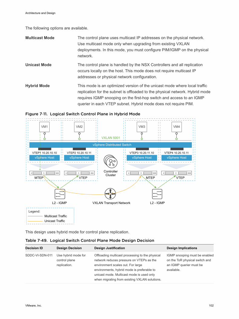
The following options are available.
Multicast Mode The control plane uses multicast IP addresses on the physical network.Use multicast mode only when upgrading from existing VXLANdeployments. In this mode, you must configure PIM/IGMP on the physicalnetwork.
Unicast Mode The control plane is handled by the NSX Controllers and all replicationoccurs locally on the host. This mode does not require multicast IPaddresses or physical network configuration.
Hybrid Mode This mode is an optimized version of the unicast mode where local trafficreplication for the subnet is offloaded to the physical network. Hybrid moderequires IGMP snooping on the first-hop switch and access to an IGMPquerier in each VTEP subnet. Hybrid mode does not require PIM.
Figure 7‑11. Logical Switch Control Plane in Hybrid Mode
VM1 VM2
vSphere Distributed Switch
vSphere Host
VXLAN 5001
VTEP1 10.20.10.10
vSphere HostVTEP2 10.20.10.11
VM3
vSphere HostVTEP3 10.20.11.10
VM4
vSphere HostVTEP4 10.20.10.11
MTEP VTEP MTEP VTEP
L2 - IGMP L2 - IGMP
Multicast TrafficUnicast Traffic
ControllerCluster
Legend:
VXLAN Transport Network
This design uses hybrid mode for control plane replication.
Table 7‑49. Logical Switch Control Plane Mode Design Decision
Decision ID Design Decision Design Justification Design Implications
SDDC-VI-SDN-011 Use hybrid mode forcontrol planereplication.
Offloading multicast processing to the physicalnetwork reduces pressure on VTEPs as theenvironment scales out. For largeenvironments, hybrid mode is preferable tounicast mode. Multicast mode is used onlywhen migrating from existing VXLAN solutions.
IGMP snooping must be enabledon the ToR physical switch andan IGMP querier must beavailable.
Architecture and Design
VMware, Inc. 102
Transport Zone DesignA transport zone is used to define the scope of a VXLAN overlay network and can span one or moreclusters within one vCenter Server domain. One or more transport zones can be configured in an NSX forvSphere solution. A transport zone is not meant to delineate a security boundary.
Note The transport zone decisions are included to facilitate easy expansion to a dual-region design thatincludes failover and recovery.
Table 7‑50. Transport Zones Design Decisions
Decision ID Design Decision Design Justification Design Implications
SDDC-VI-SDN-012
For the compute stack, use auniversal transport zone thatencompasses all shared edge andcompute, and compute clustersfrom all regions for workloads thatrequire mobility between regions.
A Universal Transport zonesupports extending networks andsecurity policies across regions.This allows seamless migration ofapplications across regions.
You can pair up to eight NSXManager instances. If the solutiongrows past eight NSX Managerinstances, you must deploy a newprimary manager and new transportzone.
SDDC-VI-SDN-013
For the compute stack, use aglobal transport zone in eachregion that encompasses allshared edge and compute, andcompute clusters .
NSX Managers with a role ofSecondary can not deploy Universalobjects. To allow all regions todeploy on demand network objectsa global transport zone is required.
Shared Edge and Compute, andCompute Pods have two transportzones.
SDDC-VI-SDN-014
For the management stack, use asingle universal transport zone thatencompasses all managementclusters.
A single Universal Transport zonesupports extending networks andsecurity policies across regions.This allows seamless migration ofthe management applicationsacross regions.
You must consider that you can pairup to eight NSX Manager instances.If the solution grows past eight NSXManager instances, you must deploya new primary manager and newtransport zone.
Routing DesignThe routing design considers different levels of routing within the environment from which to define a setof principles for designing a scalable routing solution.
Note The routing design decisions are include to facilitate easy expansion to a dual-region design andmanagement applications such as vRealize Automation.
North/south The Provider Logical Router (PLR) handles the north/south traffic to andfrom a tenant and management applications inside of application virtualnetworks.
East/west Internal east/west routing at the layer beneath the PLR deals with theapplication workloads.
Architecture and Design
VMware, Inc. 103
Table 7‑51. Routing Model Design Decisions
Decision ID Design Decision Design Justification Design Implications
SDDC-VI-SDN-017
Deploy NSX Edge ServicesGateways in an ECMPconfiguration for north/southrouting in both management andshared edge and computeclusters.
The NSX ESG is the recommendeddevice for managing north/south traffic.Using ECMP provides multiple paths inand out of the SDDC. This results infaster failover times than deployingEdge service gateways in HA mode.
ECMP requires 2 VLANS for uplinkswhich adds an additional VLAN overtraditional HA ESG configurations.
SDDC-VI-SDN-018
Deploy a single NSX UDLR forthe management cluster toprovide east/west routing acrossall regions.
Using the UDLR reduces the hop countbetween nodes attached to it to 1. Thisreduces latency and improvesperformance.
UDLRs are limited to 1,000 logicalinterfaces. When that limit isreached, a new UDLR must bedeployed.
SDDC-VI-SDN-019
Deploy a single NSX UDLR forthe shared edge and compute,and compute clusters to provideeast/west routing across allregions for workloads thatrequire mobility across regions.
Using the UDLR reduces the hop countbetween nodes attached to it to 1. Thisreduces latency and improvesperformance.
UDLRs are limited to 1,000 logicalinterfaces. When that limit isreached a new UDLR must bedeployed.
SDDC-VI-SDN-020
Deploy a DLR for the sharededge and compute and computeclusters to provide east/westrouting for workloads that requireon demand network objects fromvRealize Automation.
Using the DLR reduces the hop countbetween nodes attached to it to 1. Thisreduces latency and improvesperformance.
DLRs are limited to 1,000 logicalinterfaces. When that limit isreached a new DLR must bedeployed.
SDDC-VI-SDN-021
Deploy all NSX UDLRs withoutthe local egress option enabled.
When local egress is enabled, control ofingress traffic, is also necessary (forexample using NAT). This becomeshard to manage for little to no benefit.
All north/south traffic is routedthrough Region A until those routesare no longer available. At that time,all traffic dynamically changes toRegion B.
SDDC-VI-SDN-022
Use BGP as the dynamic routingprotocol inside the SDDC.
Using BGP as opposed to OSPF easesthe implementation of dynamic routing.There is no need to plan and designaccess to OSPF area 0 inside theSDDC. OSPF area 0 varies based oncustomer configuration.
BGP requires configuring each ESGand UDLR with the remote routerthat it exchanges routes with.
SDDC-VI-SDN-023
Configure BGP Keep Alive Timerto 1 and Hold Down Timer to 3between the UDLR and all ESGsthat provide north/south routing.
With Keep Alive and Hold Timersbetween the UDLR and ECMP ESGsset low, a failure is detected quicker, andthe routing table is updated faster.
If an ESXi host becomes resourceconstrained, the ESG running onthat host might no longer be usedeven though it is still up.
Architecture and Design
VMware, Inc. 104
Table 7‑51. Routing Model Design Decisions (Continued)
Decision ID Design Decision Design Justification Design Implications
SDDC-VI-SDN-024
Configure BGP Keep Alive Timerto 4 and Hold Down Timer to 12between the ToR switches andall ESGs providing north/southrouting.
This provides a good balance betweenfailure detection between the ToRswitches and the ESGs andoverburdening the ToRs with keep alivetraffic.
By using longer timers to detectwhen a router is dead, a deadrouter stays in the routing tablelonger and continues to send trafficto a dead router.
SDDC-VI-SDN-025
Create one or more static routeson ECMP enabled edges forsubnets behind the UDLR andDLR with a higher admin costthen the dynamically learnedroutes.
When the UDLR or DLR control VM failsover router adjacency is lost and routesfrom upstream devices such as ToRswitches to subnets behind the UDLRare lost.
This requires each ECMP edgedevice be configured with staticroutes to the UDLR or DLR. If anynew subnets are added behind theUDLR or DLR the routes must beupdated on the ECMP edges.
Transit Network and Dynamic RoutingDedicated networks are needed to facilitate traffic between the universal dynamic routers and edgegateways, and to facilitate traffic between edge gateways and the top of rack switches. These networksare used for exchanging routing tables and for carrying transit traffic.
Table 7‑52. Transit Network Design Decisions
Decision ID Design Decision Design Justification Design Implications
SDDC-VI-SDN-026
Create a universal virtual switch for use as thetransit network between the UDLR and ESGs.The UDLR provides east/west routing in bothcompute and management stacks while theESG's provide north/south routing.
The universal virtual switchallows the UDLR and all ESGsacross regions to exchangerouting information.
Only the primary NSXManager can create andmanage universal objectsincluding this UDLR.
SDDC-VI-SDN-027
Create a global virtual switch in each region foruse as the transit network between the DLR andESG's. The DLR provides east/west routing in thecompute stack while the ESG's providenorth/south routing.
The global virtual switch allowsthe DLR and ESGs in eachregion to exchange routinginformation.
A global virtual switch foruse as a transit network isrequired in each region.
SDDC-VI-SDN-028
Create two VLANs in each region. Use thoseVLANs to enable ECMP between the north/southESGs and the ToR switches.
The ToR switches have an SVI on one of the twoVLANS and each north/south ESG has aninterface on each VLAN.
This enables the ESGs to havemultiple equal-cost routes andprovides more resiliency andbetter bandwidth utilization inthe network.
Extra VLANs arerequired.
Firewall Logical DesignThe NSX Distributed Firewall is used to protect all management applications attached to applicationvirtual networks. To secure the SDDC, only other solutions in the SDDC and approved administration IPscan directly communicate with individual components. External facing portals are accessible via a loadbalancer virtual IP (VIP).
Architecture and Design
VMware, Inc. 105
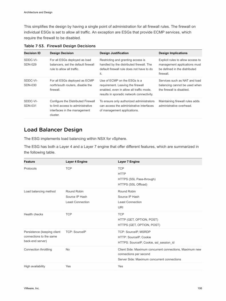
This simplifies the design by having a single point of administration for all firewall rules. The firewall onindividual ESGs is set to allow all traffic. An exception are ESGs that provide ECMP services, whichrequire the firewall to be disabled.
Table 7‑53. Firewall Design Decisions
Decision ID Design Decision Design Justification Design Implications
SDDC-VI-SDN-029
For all ESGs deployed as loadbalancers, set the default firewallrule to allow all traffic.
Restricting and granting access ishandled by the distributed firewall. Thedefault firewall rule does not have to doit.
Explicit rules to allow access tomanagement applications mustbe defined in the distributedfirewall.
SDDC-VI-SDN-030
For all ESGs deployed as ECMPnorth/south routers, disable thefirewall.
Use of ECMP on the ESGs is arequirement. Leaving the firewallenabled, even in allow all traffic mode,results in sporadic network connectivity.
Services such as NAT and loadbalancing cannot be used whenthe firewall is disabled.
SDDC-VI-SDN-031
Configure the Distributed Firewallto limit access to administrativeinterfaces in the managementcluster.
To ensure only authorized administratorscan access the administrative interfacesof management applications.
Maintaining firewall rules addsadministrative overhead.
Load Balancer DesignThe ESG implements load balancing within NSX for vSphere.
The ESG has both a Layer 4 and a Layer 7 engine that offer different features, which are summarized inthe following table.
Feature Layer 4 Engine Layer 7 Engine
Protocols TCP TCP
HTTP
HTTPS (SSL Pass-through)
HTTPS (SSL Offload)
Load balancing method Round Robin
Source IP Hash
Least Connection
Round Robin
Source IP Hash
Least Connection
URI
Health checks TCP TCP
HTTP (GET, OPTION, POST)
HTTPS (GET, OPTION, POST)
Persistence (keeping clientconnections to the sameback-end server)
TCP: SourceIP TCP: SourceIP, MSRDP
HTTP: SourceIP, Cookie
HTTPS: SourceIP, Cookie, ssl_session_id
Connection throttling No Client Side: Maximum concurrent connections, Maximum newconnections per second
Server Side: Maximum concurrent connections
High availability Yes Yes
Architecture and Design
VMware, Inc. 106
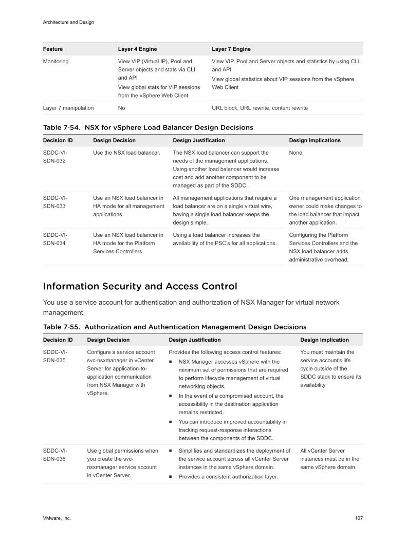
Feature Layer 4 Engine Layer 7 Engine
Monitoring View VIP (Virtual IP), Pool andServer objects and stats via CLIand API
View global stats for VIP sessionsfrom the vSphere Web Client
View VIP, Pool and Server objects and statistics by using CLIand API
View global statistics about VIP sessions from the vSphereWeb Client
Layer 7 manipulation No URL block, URL rewrite, content rewrite
Table 7‑54. NSX for vSphere Load Balancer Design Decisions
Decision ID Design Decision Design Justification Design Implications
SDDC-VI-SDN-032
Use the NSX load balancer. The NSX load balancer can support theneeds of the management applications.Using another load balancer would increasecost and add another component to bemanaged as part of the SDDC.
None.
SDDC-VI-SDN-033
Use an NSX load balancer inHA mode for all managementapplications.
All management applications that require aload balancer are on a single virtual wire,having a single load balancer keeps thedesign simple.
One management applicationowner could make changes tothe load balancer that impactanother application.
SDDC-VI-SDN-034
Use an NSX load balancer inHA mode for the PlatformServices Controllers.
Using a load balancer increases theavailability of the PSC’s for all applications.
Configuring the PlatformServices Controllers and theNSX load balancer addsadministrative overhead.
Information Security and Access ControlYou use a service account for authentication and authorization of NSX Manager for virtual networkmanagement.
Table 7‑55. Authorization and Authentication Management Design Decisions
Decision ID Design Decision Design Justification Design Implication
SDDC-VI-SDN-035
Configure a service accountsvc-nsxmanager in vCenterServer for application-to-application communicationfrom NSX Manager withvSphere.
Provides the following access control features:n NSX Manager accesses vSphere with the
minimum set of permissions that are requiredto perform lifecycle management of virtualnetworking objects.
n In the event of a compromised account, theaccessibility in the destination applicationremains restricted.
n You can introduce improved accountability intracking request-response interactionsbetween the components of the SDDC.
You must maintain theservice account's lifecycle outside of theSDDC stack to ensure itsavailability
SDDC-VI-SDN-036
Use global permissions whenyou create the svc-nsxmanager service accountin vCenter Server.
n Simplifies and standardizes the deployment ofthe service account across all vCenter Serverinstances in the same vSphere domain.
n Provides a consistent authorization layer.
All vCenter Serverinstances must be in thesame vSphere domain.
Architecture and Design
VMware, Inc. 107
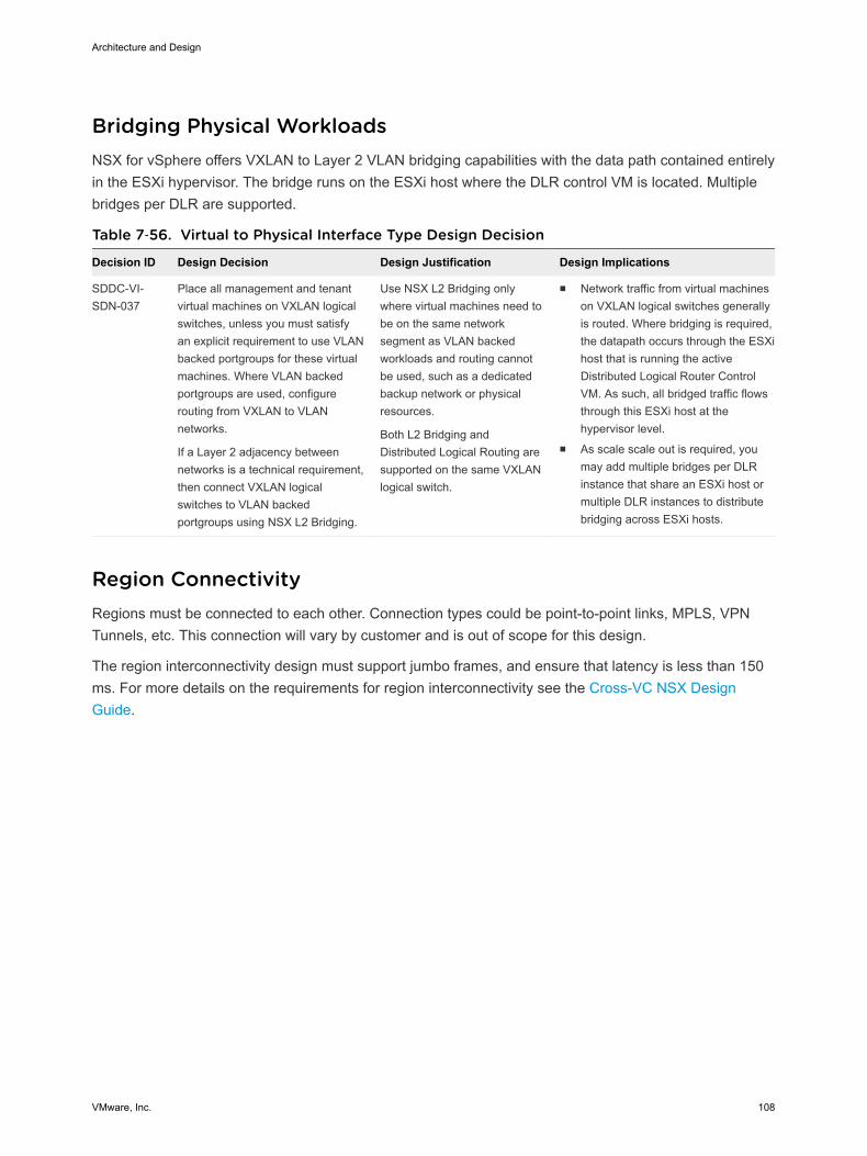
Bridging Physical WorkloadsNSX for vSphere offers VXLAN to Layer 2 VLAN bridging capabilities with the data path contained entirelyin the ESXi hypervisor. The bridge runs on the ESXi host where the DLR control VM is located. Multiplebridges per DLR are supported.
Table 7‑56. Virtual to Physical Interface Type Design Decision
Decision ID Design Decision Design Justification Design Implications
SDDC-VI-SDN-037
Place all management and tenantvirtual machines on VXLAN logicalswitches, unless you must satisfyan explicit requirement to use VLANbacked portgroups for these virtualmachines. Where VLAN backedportgroups are used, configurerouting from VXLAN to VLANnetworks.
If a Layer 2 adjacency betweennetworks is a technical requirement,then connect VXLAN logicalswitches to VLAN backedportgroups using NSX L2 Bridging.
Use NSX L2 Bridging onlywhere virtual machines need tobe on the same networksegment as VLAN backedworkloads and routing cannotbe used, such as a dedicatedbackup network or physicalresources.
Both L2 Bridging andDistributed Logical Routing aresupported on the same VXLANlogical switch.
n Network traffic from virtual machineson VXLAN logical switches generallyis routed. Where bridging is required,the datapath occurs through the ESXihost that is running the activeDistributed Logical Router ControlVM. As such, all bridged traffic flowsthrough this ESXi host at thehypervisor level.
n As scale scale out is required, youmay add multiple bridges per DLRinstance that share an ESXi host ormultiple DLR instances to distributebridging across ESXi hosts.
Region ConnectivityRegions must be connected to each other. Connection types could be point-to-point links, MPLS, VPNTunnels, etc. This connection will vary by customer and is out of scope for this design.
The region interconnectivity design must support jumbo frames, and ensure that latency is less than 150ms. For more details on the requirements for region interconnectivity see the Cross-VC NSX DesignGuide.
Architecture and Design
VMware, Inc. 108
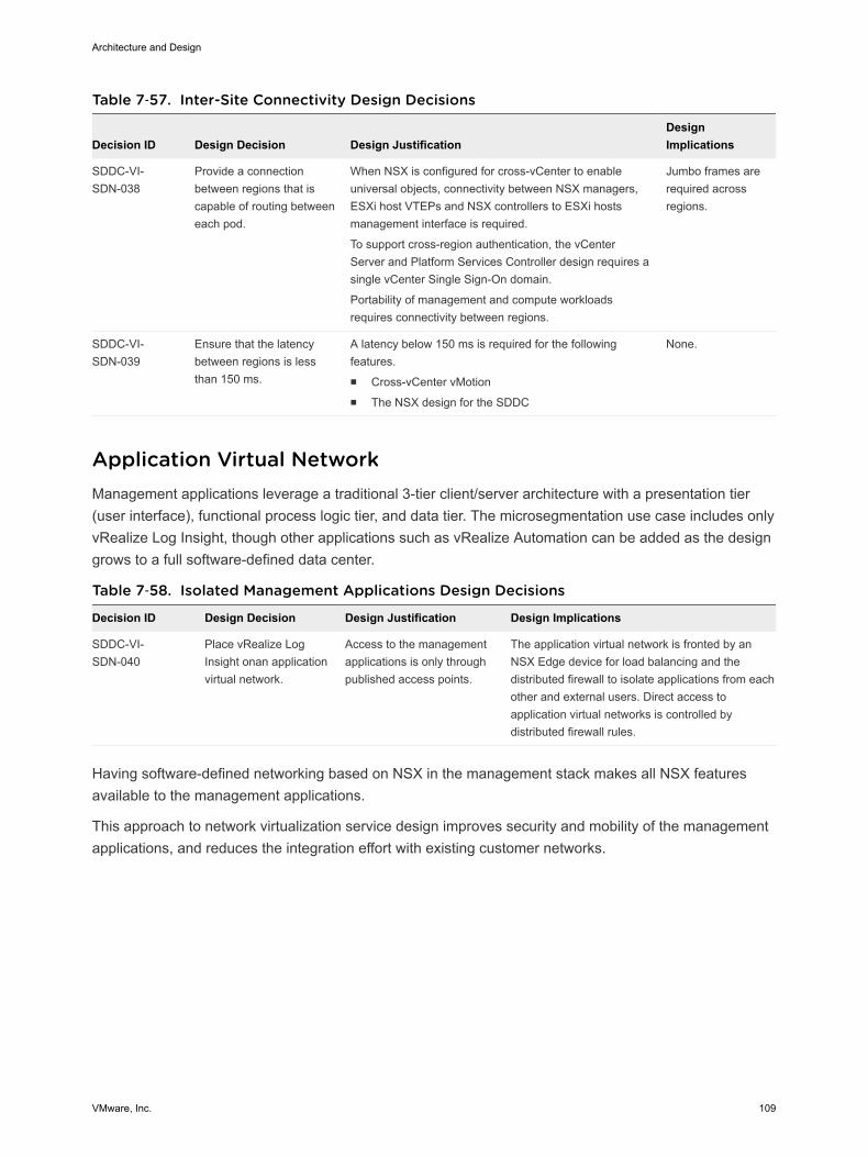
Table 7‑57. Inter-Site Connectivity Design Decisions
Decision ID Design Decision Design JustificationDesignImplications
SDDC-VI-SDN-038
Provide a connectionbetween regions that iscapable of routing betweeneach pod.
When NSX is configured for cross-vCenter to enableuniversal objects, connectivity between NSX managers,ESXi host VTEPs and NSX controllers to ESXi hostsmanagement interface is required.
To support cross-region authentication, the vCenterServer and Platform Services Controller design requires asingle vCenter Single Sign-On domain.
Portability of management and compute workloadsrequires connectivity between regions.
Jumbo frames arerequired acrossregions.
SDDC-VI-SDN-039
Ensure that the latencybetween regions is lessthan 150 ms.
A latency below 150 ms is required for the followingfeatures.n Cross-vCenter vMotionn The NSX design for the SDDC
None.
Application Virtual NetworkManagement applications leverage a traditional 3-tier client/server architecture with a presentation tier(user interface), functional process logic tier, and data tier. The microsegmentation use case includes onlyvRealize Log Insight, though other applications such as vRealize Automation can be added as the designgrows to a full software-defined data center.
Table 7‑58. Isolated Management Applications Design Decisions
Decision ID Design Decision Design Justification Design Implications
SDDC-VI-SDN-040
Place vRealize LogInsight onan applicationvirtual network.
Access to the managementapplications is only throughpublished access points.
The application virtual network is fronted by anNSX Edge device for load balancing and thedistributed firewall to isolate applications from eachother and external users. Direct access toapplication virtual networks is controlled bydistributed firewall rules.
Having software-defined networking based on NSX in the management stack makes all NSX featuresavailable to the management applications.
This approach to network virtualization service design improves security and mobility of the managementapplications, and reduces the integration effort with existing customer networks.
Architecture and Design
VMware, Inc. 109
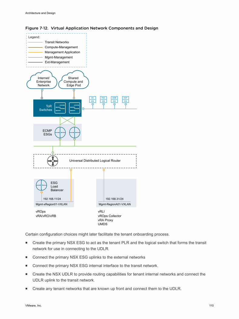
Figure 7‑12. Virtual Application Network Components and Design
VC
OSPSC
OSSRM
OSVDP
OS
ECMPESGs
ToRSwitches
Internet/EnterpriseNetwork
Mgmt-Management
Compute-Management
Legend:
Shared Compute and
Edge Pod
192.168.11/24
Transit Networks
Management Application
vRLIvROps CollectorvRA Proxy
vRA/vRO/vRBvROps
Universal Distributed Logical Router
ESGLoadBalancer
Mgmt-xRegion01-VXLAN
192.168.31/24
Mgmt-RegionA01-VXLAN
Ext-Management
UMDS
Certain configuration choices might later facilitate the tenant onboarding process.
n Create the primary NSX ESG to act as the tenant PLR and the logical switch that forms the transitnetwork for use in connecting to the UDLR.
n Connect the primary NSX ESG uplinks to the external networks
n Connect the primary NSX ESG internal interface to the transit network.
n Create the NSX UDLR to provide routing capabilities for tenant internal networks and connect theUDLR uplink to the transit network.
n Create any tenant networks that are known up front and connect them to the UDLR.
Architecture and Design
VMware, Inc. 110
Use of Secure Sockets Layer (SSL) CertificatesBy default, NSX Manager uses a self-signed SSL certificate. This certificate is not trusted by end-userdevices or web browsers. It is a security best practice to replace these certificates with certificates thatare signed by a third-party or enterprise Certificate Authority (CA).
Design ID Design Decision Design Justification Design Implication
SDDC-VI-SDN-043
Replace the NSX Manager certificatewith a certificate signed by a third-partyPublic Key Infrastructure.
Ensures communication between NSXadministrators and the NSX Managerare encrypted by a trusted certificate.
Replacing and managingcertificates is anoperational overhead.
Shared Storage DesignThe shared storage design includes design decisions for vSAN storage and NFS storage.
Well-designed shared storage provides the basis for an SDDC and has the following benefits.
n Prevents unauthorized access to business data
n Protects data from hardware and software failures
n Protects data from malicious or accidental corruption
Follow these guidelines when designing shared storage for your environment.
n Optimize the storage design to meet the diverse needs of applications, services, administrators, andusers.
n Strategically align business applications and the storage infrastructure to reduce costs, boostperformance, improve availability, provide security, and enhance functionality.
n Provide multiple tiers of storage to match application data access to application requirements.
n Design each tier of storage with different performance, capacity, and availability characteristics.Because not every application requires expensive, high-performance, highly available storage,designing different storage tiers reduces cost.
Shared Storage PlatformYou can choose between traditional storage, VMware vSphere Virtual Volumes, and VMware vSANstorage.
Architecture and Design
VMware, Inc. 111
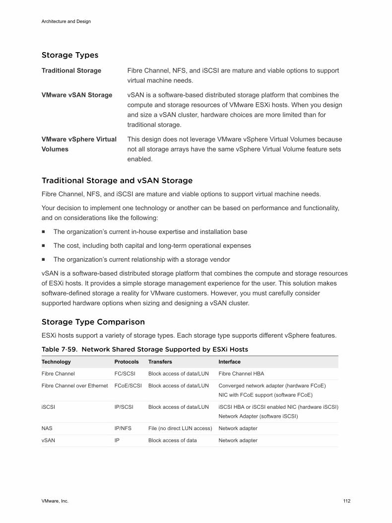
Storage Types
Traditional Storage Fibre Channel, NFS, and iSCSI are mature and viable options to supportvirtual machine needs.
VMware vSAN Storage vSAN is a software-based distributed storage platform that combines thecompute and storage resources of VMware ESXi hosts. When you designand size a vSAN cluster, hardware choices are more limited than fortraditional storage.
VMware vSphere VirtualVolumes
This design does not leverage VMware vSphere Virtual Volumes becausenot all storage arrays have the same vSphere Virtual Volume feature setsenabled.
Traditional Storage and vSAN StorageFibre Channel, NFS, and iSCSI are mature and viable options to support virtual machine needs.
Your decision to implement one technology or another can be based on performance and functionality,and on considerations like the following:
n The organization’s current in-house expertise and installation base
n The cost, including both capital and long-term operational expenses
n The organization’s current relationship with a storage vendor
vSAN is a software-based distributed storage platform that combines the compute and storage resourcesof ESXi hosts. It provides a simple storage management experience for the user. This solution makessoftware-defined storage a reality for VMware customers. However, you must carefully considersupported hardware options when sizing and designing a vSAN cluster.
Storage Type ComparisonESXi hosts support a variety of storage types. Each storage type supports different vSphere features.
Table 7‑59. Network Shared Storage Supported by ESXi Hosts
Technology Protocols Transfers Interface
Fibre Channel FC/SCSI Block access of data/LUN Fibre Channel HBA
Fibre Channel over Ethernet FCoE/SCSI Block access of data/LUN Converged network adapter (hardware FCoE)
NIC with FCoE support (software FCoE)
iSCSI IP/SCSI Block access of data/LUN iSCSI HBA or iSCSI enabled NIC (hardware iSCSI)
Network Adapter (software iSCSI)
NAS IP/NFS File (no direct LUN access) Network adapter
vSAN IP Block access of data Network adapter
Architecture and Design
VMware, Inc. 112
Table 7‑60. vSphere Features Supported by Storage Type
TypevSpherevMotion Datastore
Raw DeviceMapping (RDM)
Application orBlock-levelClustering HA/DRS
Storage APIsData Protection
Local Storage Yes VMFS No Yes No Yes
Fibre Channel /Fibre Channel overEthernet
Yes VMFS Yes Yes Yes Yes
iSCSI Yes VMFS Yes Yes Yes Yes
NAS over NFS Yes NFS No No Yes Yes
vSAN Yes vSAN No Yes (via iSCSIInitiator)
Yes Yes
Shared Storage Logical DesignThe shared storage design selects the appropriate storage device for each type of cluster.
The storage devices for use by each type of cluster are as follows.
n Management clusters use vSAN for primary storage and NFS for secondary storage.
n Shared edge and compute clusters can use FC/FCoE, iSCSI, NFS, or vSAN storage. No specificguidance is given as user workloads and other factors determine storage type and SLA for userworkloads.
Architecture and Design
VMware, Inc. 113
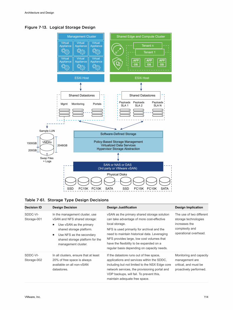
Figure 7‑13. Logical Storage Design
Virtual Appliance
Virtual Appliance
Virtual Appliance
Virtual Appliance
Virtual Appliance
Virtual Appliance APP
OSAPPOS
APPOS
Tenant n
Management Cluster Shared Edge and Compute Cluster
Tenant 1
ESXi Host ESXi Host
Shared Datastores
Mgmt Monitoring Portals
Shared Datastores
PayloadsSLA 1
PayloadsSLA 2
PayloadsSLA N
Software-Defined Storage
Policy-Based Storage ManagementVirtualized Data Services
Hypervisor Storage Abstraction
SAN or NAS or DAS(3rd party or VMware vSAN)
Physical Disks
SSD FC15K FC10K SATA SSD FC15K FC10K SATA
VMDKs
Swap Files + Logs
1500GB
200GB
2048GB
Sample LUN
Table 7‑61. Storage Type Design Decisions
Decision ID Design Decision Design Justification Design Implication
SDDC-VI-Storage-001
In the management cluster, usevSAN and NFS shared storage:n Use vSAN as the primary
shared storage platform.n Use NFS as the secondary
shared storage platform for themanagement cluster.
vSAN as the primary shared storage solutioncan take advantage of more cost-effectivelocal storage.
NFS is used primarily for archival and theneed to maintain historical data. LeveragingNFS provides large, low cost volumes thathave the flexibility to be expanded on aregular basis depending on capacity needs.
The use of two differentstorage technologiesincreases thecomplexity andoperational overhead.
SDDC-VI-Storage-002
In all clusters, ensure that at least20% of free space is alwaysavailable on all non-vSANdatastores.
If the datastore runs out of free space,applications and services within the SDDC,including but not limited to the NSX Edge corenetwork services, the provisioning portal andVDP backups, will fail. To prevent this,maintain adequate free space.
Monitoring and capacitymanagement arecritical, and must beproactively performed.
Architecture and Design
VMware, Inc. 114
Storage TieringNot all application workloads have the same storage requirements. Storage tiering allows for thesedifferences by creating multiple levels of storage with varying degrees of performance, reliability and cost,depending on the application workload needs.
Today’s enterprise-class storage arrays contain multiple drive types and protection mechanisms. Thestorage, server, and application administrators face challenges when selecting the correct storageconfiguration for each application being deployed in the environment. Virtualization can make thisproblem more challenging by consolidating many different application workloads onto a small number oflarge devices.
The most mission-critical data typically represents the smallest amount of data and offline data representsthe largest amount. Details differ for different organizations.
To determine the storage tier for application data, determine the storage characteristics of the applicationor service.
n I/O operations per second (IOPS) requirements
n Megabytes per second (MBps) requirements
n Capacity requirements
n Availability requirements
n Latency requirements
After you determine the information for each application, you can move the application to the storage tierwith matching characteristics.
n Consider any existing service-level agreements (SLAs).
n Move data between storage tiers during the application lifecycle as needed.
VMware Hardware Acceleration API/CLI for StorageThe VMware Hardware Acceleration API/CLI for storage (previously known as vStorage APIs for ArrayIntegration or VAAI), supports a set of ESXCLI commands for enabling communication between ESXihosts and storage devices. Using this API/CLI has several advantages.
The APIs define a set of storage primitives that enable the ESXi host to offload certain storage operationsto the array. Offloading the operations reduces resource overhead on the ESXi hosts and can significantlyimprove performance for storage-intensive operations such as storage cloning, zeroing, and so on. Thegoal of hardware acceleration is to help storage vendors provide hardware assistance to speed upVMware I/O operations that are more efficiently accomplished in the storage hardware.
Without the use of VAAI, cloning or migration of virtual machines by the VMkernel data mover involvessoftware data movement. The data mover issues I/O to read and write blocks to and from the source anddestination datastores. With VAAI, the data mover can use the API primitives to offload operations to thearray when possible. For example, when you copy a virtual machine disk file (VMDK file) from one
Architecture and Design
VMware, Inc. 115
datastore to another inside the same array, the data mover directs the array to make the copy completelyinside the array. If you invoke a data movement operation and the corresponding hardware offloadoperation is enabled, the data mover first attempts to use hardware offload. If the hardware offloadoperation fails, the data mover reverts to the traditional software method of data movement.
In nearly all cases, hardware data movement performs significantly better than software data movement.It consumes fewer CPU cycles and less bandwidth on the storage fabric. Timing operations that use theVAAI primitives and use esxtop to track values such as CMDS/s, READS/s, WRITES/s, MBREAD/s, andMBWRTN/s of storage adapters during the operation show performance improvements.
Table 7‑62. vStorage APIs for Array Integration Design Decision
Decision ID Design Decision Design Justification Design Implication
SDDC-VI-Storage-003
Select an array thatsupports VAAI overNAS (NFS).
VAAI offloads tasks to the array itself, enablingthe ESXi hypervisor to use its resources forapplication workloads and not become abottleneck in the storage subsystem.
VAAI is required to support the desired numberof virtual machine lifecycle operations.
Not all VAAI arrays supportVAAI over NFS. A plugin fromthe array vendor is required toenable this functionality.
Architecture and Design
VMware, Inc. 116
Virtual Machine Storage PoliciesYou can create a storage policy for a virtual machine to specify which storage capabilities andcharacteristics are the best match for this virtual machine.
Note vSAN uses storage policies to allow specification of the characteristics of virtual machines, so youcan define the policy on an individual disk level rather than at the volume level for vSAN.
You can identify the storage subsystem capabilities by using the VMware vSphere API for StorageAwareness or by using a user-defined storage policy.
VMware vSphere APIfor Storage Awareness(VASA)
With vSphere API for Storage Awareness, storage vendors can publish thecapabilities of their storage to VMware vCenter Server, which can displaythese capabilities in its user interface.
User-defined storagepolicy
You define the storage policy using the VMware Storage Policy SDK,VMware vSphere PowerCLI, or vSphere Web Client.
You can assign a storage policy to a virtual machine and periodically check for compliance so that thevirtual machine continues to run on storage with the correct performance and availability characteristics.
You can associate a virtual machine with a virtual machine storage policy when you create, clone, ormigrate that virtual machine. If a virtual machine is associated with a storage policy, the vSphere WebClient shows the datastores that are compatible with the policy. You can select a datastore or datastorecluster. If you select a datastore that does not match the virtual machine storage policy, the vSphere WebClient shows that the virtual machine is using non-compliant storage. See Creating and ManagingvSphere Storage Policies in the vSphere 6.5 documentation.
Table 7‑63. Virtual Machine Storage Policy Design Decision
Decision ID Design Decision Design Justification Design Implication
SDDC-VI-Storage-004 Use the default vSAN storagepolicy for all virtual machines inthe management cluster.
The default vSAN storagepolicy is adequate for themanagement cluster VMs.
If third-party or additional VMs havedifferent storage requirements,additional VM storage policies maybe required.
vSphere Storage I/O Control DesignVMware vSphere Storage I/O Control allows cluster-wide storage I/O prioritization, which results in betterworkload consolidation and helps reduce extra costs associated with over provisioning.
vSphere Storage I/O Control extends the constructs of shares and limits to storage I/O resources. Youcan control the amount of storage I/O that is allocated to virtual machines during periods of I/Ocongestion, so that more important virtual machines get preference over less important virtual machinesfor I/O resource allocation.
Architecture and Design
VMware, Inc. 117
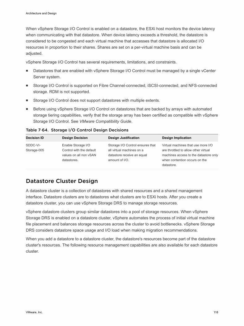
When vSphere Storage I/O Control is enabled on a datastore, the ESXi host monitors the device latencywhen communicating with that datastore. When device latency exceeds a threshold, the datastore isconsidered to be congested and each virtual machine that accesses that datastore is allocated I/Oresources in proportion to their shares. Shares are set on a per-virtual machine basis and can beadjusted.
vSphere Storage I/O Control has several requirements, limitations, and constraints.
n Datastores that are enabled with vSphere Storage I/O Control must be managed by a single vCenterServer system.
n Storage I/O Control is supported on Fibre Channel-connected, iSCSI-connected, and NFS-connectedstorage. RDM is not supported.
n Storage I/O Control does not support datastores with multiple extents.
n Before using vSphere Storage I/O Control on datastores that are backed by arrays with automatedstorage tiering capabilities, verify that the storage array has been certified as compatible with vSphereStorage I/O Control. See VMware Compatibility Guide.
Table 7‑64. Storage I/O Control Design Decisions
Decision ID Design Decision Design Justification Design Implication
SDDC-VI-Storage-005
Enable Storage I/OControl with the defaultvalues on all non vSANdatastores.
Storage I/O Control ensures thatall virtual machines on adatastore receive an equalamount of I/O.
Virtual machines that use more I/Oare throttled to allow other virtualmachines access to the datastore onlywhen contention occurs on thedatastore.
Datastore Cluster DesignA datastore cluster is a collection of datastores with shared resources and a shared managementinterface. Datastore clusters are to datastores what clusters are to ESXi hosts. After you create adatastore cluster, you can use vSphere Storage DRS to manage storage resources.
vSphere datastore clusters group similar datastores into a pool of storage resources. When vSphereStorage DRS is enabled on a datastore cluster, vSphere automates the process of initial virtual machinefile placement and balances storage resources across the cluster to avoid bottlenecks. vSphere StorageDRS considers datastore space usage and I/O load when making migration recommendations.
When you add a datastore to a datastore cluster, the datastore's resources become part of the datastorecluster's resources. The following resource management capabilities are also available for each datastorecluster.
Architecture and Design
VMware, Inc. 118
Capability Description
Space utilization loadbalancing
You can set a threshold for space use. When space use on a datastore exceeds the threshold, vSphereStorage DRS generates recommendations or performs migrations with vSphere Storage vMotion to balancespace use across the datastore cluster.
I/O latency loadbalancing
You can configure the I/O latency threshold to avoid bottlenecks. When I/O latency on a datastore exceedsthe threshold, vSphere Storage DRS generates recommendations or performs vSphere Storage vMotionmigrations to help alleviate high I/O load.
Anti-affinity rules You can configure anti-affinity rules for virtual machine disks to ensure that the virtual disks of a virtualmachine are kept on different datastores. By default, all virtual disks for a virtual machine are placed on thesame datastore.
You can enable vSphere Storage I/O Control or vSphere Storage DRS for a datastore cluster. You canenable the two features separately, even though vSphere Storage I/O control is enabled by default whenyou enable vSphere Storage DRS.
vSphere Storage DRS Background InformationvSphere Storage DRS supports automating the management of datastores based on latency and storageutilization. When configuring vSphere Storage DRS, verify that all datastores use the same version ofVMFS and are on the same storage subsystem. Because vSphere Storage vMotion performs themigration of the virtual machines, confirm that all prerequisites are met.
vSphere Storage DRS provides a way of balancing usage and IOPS among datastores in a storagecluster:
n Initial placement of virtual machines is based on storage capacity.
n vSphere Storage DRS uses vSphere Storage vMotion to migrate virtual machines based on storagecapacity.
n vSphere Storage DRS uses vSphere Storage vMotion to migrate virtual machines based on I/Olatency.
n You can configure vSphere Storage DRS to run in either manual mode or in fully automated mode.
vSphere vStorage I/O Control and vSphere Storage DRS manage latency differently.
n vSphere Storage I/O Control distributes the resources based on virtual disk share value after alatency threshold is reached.
n vSphere Storage DRS measures latency over a period of time. If the latency threshold of vSphereStorage DRS is met in that time frame, vSphere Storage DRS migrates virtual machines to balancelatency across the datastores that are part of the cluster.
When making a vSphere Storage design decision, consider these points:
n Use vSphere Storage DRS where possible.
n vSphere Storage DRS provides a way of balancing usage and IOPS among datastores in a storagecluster:
n Initial placement of virtual machines is based on storage capacity.
Architecture and Design
VMware, Inc. 119
n vSphere Storage vMotion is used to migrate virtual machines based on storage capacity.
n vSphere Storage vMotion is used to migrate virtual machines based on I/O latency.
n vSphere Storage DRS can be configured in either manual or fully automated modes
vSAN Storage DesignVMware vSAN Storage design in this VMware Validated Design includes conceptual design, logicaldesign, network design, cluster and disk group design, and policy design.
VMware vSAN Conceptual Design and Logical DesignThis VMware vSAN design is limited to the management cluster. The design uses the default storagepolicy to achieve redundancy and performance within the cluster.
VMware vSAN Conceptual Design
While vSAN can be used within the shared edge and compute cluster, this design currently gives noguidance for the implementation.
Architecture and Design
VMware, Inc. 120
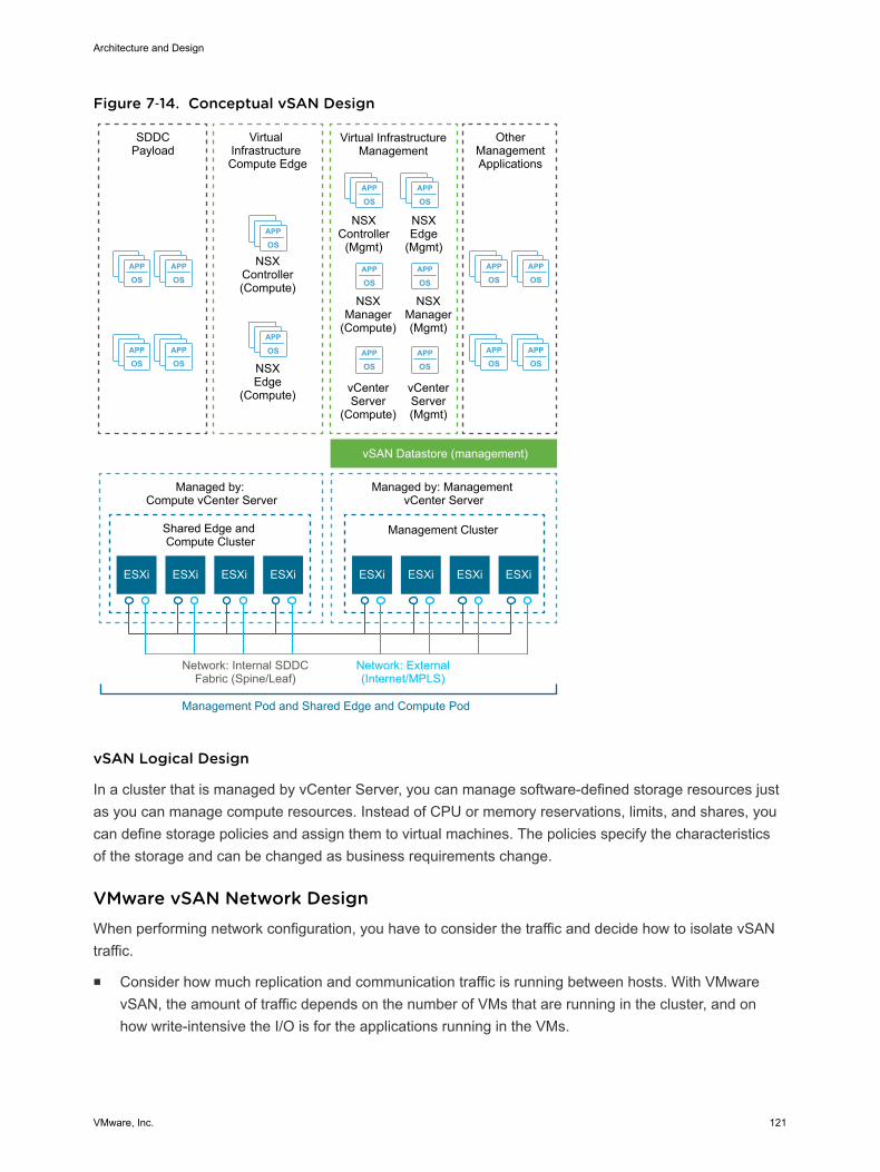
Figure 7‑14. Conceptual vSAN Design
APP
OSAPP
OS
APP
OSAPP
OS
APP
OSAPP
OS
APP
OSAPP
OS
APP
OS
APP
OS
APP
OSAPP
OS
APP
OSAPP
OS
APP
OSAPP
OS
ESXi ESXi
Virtual InfrastructureManagement
NSXController
(Mgmt)
OtherManagementApplications
NSXEdge
(Mgmt)
NSXManager(Mgmt)
NSXManager
(Compute)
NSXEdge
(Compute)
NSXController(Compute)
ESXi ESXi ESXi ESXi ESXi ESXi
SDDCPayload
Virtual Infrastructure Compute Edge
vSAN Datastore (management)
Shared Edge and Compute Cluster
Management Cluster
Managed by: Compute vCenter Server
Managed by: Management vCenter Server
Network: External(Internet/MPLS)
Network: Internal SDDCFabric (Spine/Leaf)
Management Pod and Shared Edge and Compute Pod
vCenterServer(Mgmt)
vCenterServer
(Compute)
vSAN Logical Design
In a cluster that is managed by vCenter Server, you can manage software-defined storage resources justas you can manage compute resources. Instead of CPU or memory reservations, limits, and shares, youcan define storage policies and assign them to virtual machines. The policies specify the characteristicsof the storage and can be changed as business requirements change.
VMware vSAN Network DesignWhen performing network configuration, you have to consider the traffic and decide how to isolate vSANtraffic.
n Consider how much replication and communication traffic is running between hosts. With VMwarevSAN, the amount of traffic depends on the number of VMs that are running in the cluster, and onhow write-intensive the I/O is for the applications running in the VMs.
Architecture and Design
VMware, Inc. 121
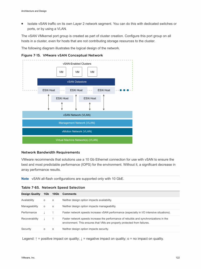
n Isolate vSAN traffic on its own Layer 2 network segment. You can do this with dedicated switches orports, or by using a VLAN.
The vSAN VMkernel port group is created as part of cluster creation. Configure this port group on allhosts in a cluster, even for hosts that are not contributing storage resources to the cluster.
The following diagram illustrates the logical design of the network.
Figure 7‑15. VMware vSAN Conceptual Network
VM VM VM
ESXi Host ESXi Host ESXi Host
ESXi Host ESXi Host
vSAN Datastore
vSAN-Enabled Clusters
vSAN Network (VLAN)
Management Network (VLAN)
vMotion Network (VLAN)
Virtual Machine Network(s) (VLAN)
Network Bandwidth Requirements
VMware recommends that solutions use a 10 Gb Ethernet connection for use with vSAN to ensure thebest and most predictable performance (IOPS) for the environment. Without it, a significant decrease inarray performance results.
Note vSAN all-flash configurations are supported only with 10 GbE.
Table 7‑65. Network Speed Selection
Design Quality 1Gb 10Gb Comments
Availability o o Neither design option impacts availability.
Manageability o o Neither design option impacts manageability.
Performance ↓ ↑ Faster network speeds increase vSAN performance (especially in I/O intensive situations).
Recoverability ↓ ↑ Faster network speeds increase the performance of rebuilds and synchronizations in theenvironment. This ensures that VMs are properly protected from failures.
Security o o Neither design option impacts security.
Legend: ↑ = positive impact on quality; ↓ = negative impact on quality; o = no impact on quality.
Architecture and Design
VMware, Inc. 122
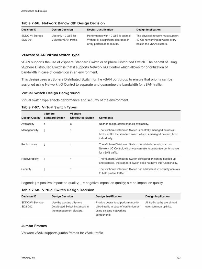
Table 7‑66. Network Bandwidth Design Decision
Decision ID Design Decision Design Justification Design Implication
SDDC-VI-Storage-SDS-001
Use only 10 GbE forVMware vSAN traffic.
Performance with 10 GbE is optimal.Without it, a significant decrease inarray performance results.
The physical network must support10 Gb networking between everyhost in the vSAN clusters.
VMware vSAN Virtual Switch Type
vSAN supports the use of vSphere Standard Switch or vSphere Distributed Switch. The benefit of usingvSphere Distributed Switch is that it supports Network I/O Control which allows for prioritization ofbandwidth in case of contention in an environment.
This design uses a vSphere Distributed Switch for the vSAN port group to ensure that priority can beassigned using Network I/O Control to separate and guarantee the bandwidth for vSAN traffic.
Virtual Switch Design Background
Virtual switch type affects performance and security of the environment.
Table 7‑67. Virtual Switch Types
Design QualityvSphereStandard Switch
vSphereDistributed Switch Comments
Availability o o Neither design option impacts availability.
Manageability ↓ ↑ The vSphere Distributed Switch is centrally managed across allhosts, unlike the standard switch which is managed on each hostindividually.
Performance ↓ ↑ The vSphere Distributed Switch has added controls, such asNetwork I/O Control, which you can use to guarantee performancefor vSAN traffic.
Recoverability ↓ ↑ The vSphere Distributed Switch configuration can be backed upand restored, the standard switch does not have this functionality.
Security ↓ ↑ The vSphere Distributed Switch has added built-in security controlsto help protect traffic.
Legend: ↑ = positive impact on quality; ↓ = negative impact on quality; o = no impact on quality.
Table 7‑68. Virtual Switch Design Decision
Decision ID Design Decision Design Justification Design Implication
SDDC-VI-Storage-SDS-002
Use the existing vSphereDistributed Switch instances inthe management clusters.
Provide guaranteed performance forvSAN traffic in case of contention byusing existing networkingcomponents.
All traffic paths are sharedover common uplinks.
Jumbo Frames
VMware vSAN supports jumbo frames for vSAN traffic.
Architecture and Design
VMware, Inc. 123
A VMware vSAN design should use jumbo frames only if the physical environment is already configuredto support them, they are part of the existing design, or if the underlying configuration does not create asignificant amount of added complexity to the design.
Table 7‑69. Jumbo Frames Design Decision
Decision ID Design Decision Design Justification Design Implication
SDDC-VI-Storage-SDS-003
Configure jumbo frames onthe VLAN dedicated to vSANtraffic.
Jumbo frames are already used toimprove performance of vSpherevMotion and NFS storage traffic.
Every device in the networkmust support jumbo frames.
VLANs
VMware recommends isolating VMware vSAN traffic on its own VLAN. When a design uses multiplevSAN clusters, each cluster should use a dedicated VLAN or segment for its traffic. This approachprevents interference between clusters and helps with troubleshooting cluster configuration.
Table 7‑70. VLAN Design Decision
Decision ID Design Decision Design Justification Design Implication
SDDC-VI-Storage-SDS-004
Use a dedicated VLAN forvSAN traffic for each vSANenabled cluster.
VLANs ensure trafficisolation.
VLANs span only a single pod.
A sufficient number of VLANs are availablewithin each pod and should be used for trafficsegregation.
Multicast Requirements
VMware vSAN requires that IP multicast is enabled on the Layer 2 physical network segment that is usedfor intra-cluster communication. All VMkernel ports on the vSAN network subscribe to a multicast groupusing Internet Group Management Protocol (IGMP).
A default multicast address is assigned to each vSAN cluster at the time of creation. IGMP (v3) snoopingis used to limit Layer 2 multicast traffic to specific port groups. As per the Physical Network Design, IGMPsnooping is configured with an IGMP snooping querier to limit the physical switch ports that participate inthe multicast group to only vSAN VMkernel port uplinks. In some cases, an IGMP snooping querier canbe associated with a specific VLAN. However, vendor implementations might differ.
Cluster and Disk Group DesignWhen considering the cluster and disk group design, you have to decide on the vSAN datastore size,number of hosts per cluster, number of disk groups per host, and the vSAN policy.
VMware vSAN Datastore Size
The size of the VMware vSAN datastore depends on the requirements for the datastore. Consider costversus availability to provide the appropriate sizing.
Architecture and Design
VMware, Inc. 124
Table 7‑71. VMware vSAN Datastore Design Decision
Decision ID Design Decision Design Justification Design Implication
SDDC-VI-Storage-SDS-005
Provide the Management clusterwith a minimum of 8TB of rawcapacity for vSAN.
Management cluster virtual machines that usevSAN require at least 8 TB of raw storage.
NFS is used as secondary shared storage ofsome management components such asbackups and log archives.
None
SDDC-VI-Storage-SDS-006
On all VSAN datastores , ensurethat at least 30% of free space isalways available.
When vSAN reaches 80% usage a re-balancetask is started which can be resourceintensive.
Increases the amountof available storageneeded.
Number of Hosts Per Cluster
The number of hosts in the cluster depends on these factors:
n Amount of available space on the vSAN datastore
n Number of failures you can tolerate in the cluster
For example, if the vSAN cluster has only 3 ESXi hosts, only a single failure is supported. If a higher levelof availability is required, additional hosts are required.
Cluster Size Design Background
Table 7‑72. Number of Hosts Per Cluster
Design Quality 3 Hosts 32 Hosts 64 Hosts Comments
Availability ↓ ↑ ↑↑ The more hosts that are available in the cluster, the more failures the clustercan tolerate.
Manageability ↓ ↑ ↑ The more hosts in the cluster, the more virtual machines can be in the vSANenvironment.
Performance ↑ ↓ ↓ Having a larger cluster can impact performance if there is an imbalance ofresources. Consider performance as you make your decision.
Recoverability o o o Neither design option impacts recoverability.
Security o o o Neither design option impacts security.
Legend: ↑ = positive impact on quality; ↓ = negative impact on quality; o = no impact on quality.
Table 7‑73. Cluster Size Design Decision
Decision ID Design Decision Design Justification Design Implication
SDDC-VI-Storage-SDS-007
Configure the Managementcluster with a minimum of 4ESXi hosts to support vSAN.
Having 4 hosts addresses the availabilityand sizing requirements, and allows youto take an ESXi host offline formaintenance or upgrades withoutimpacting the overall vSAN cluster health.
The availability requirements forthe management cluster mightcause underutilization of thecluster hosts.
Architecture and Design
VMware, Inc. 125
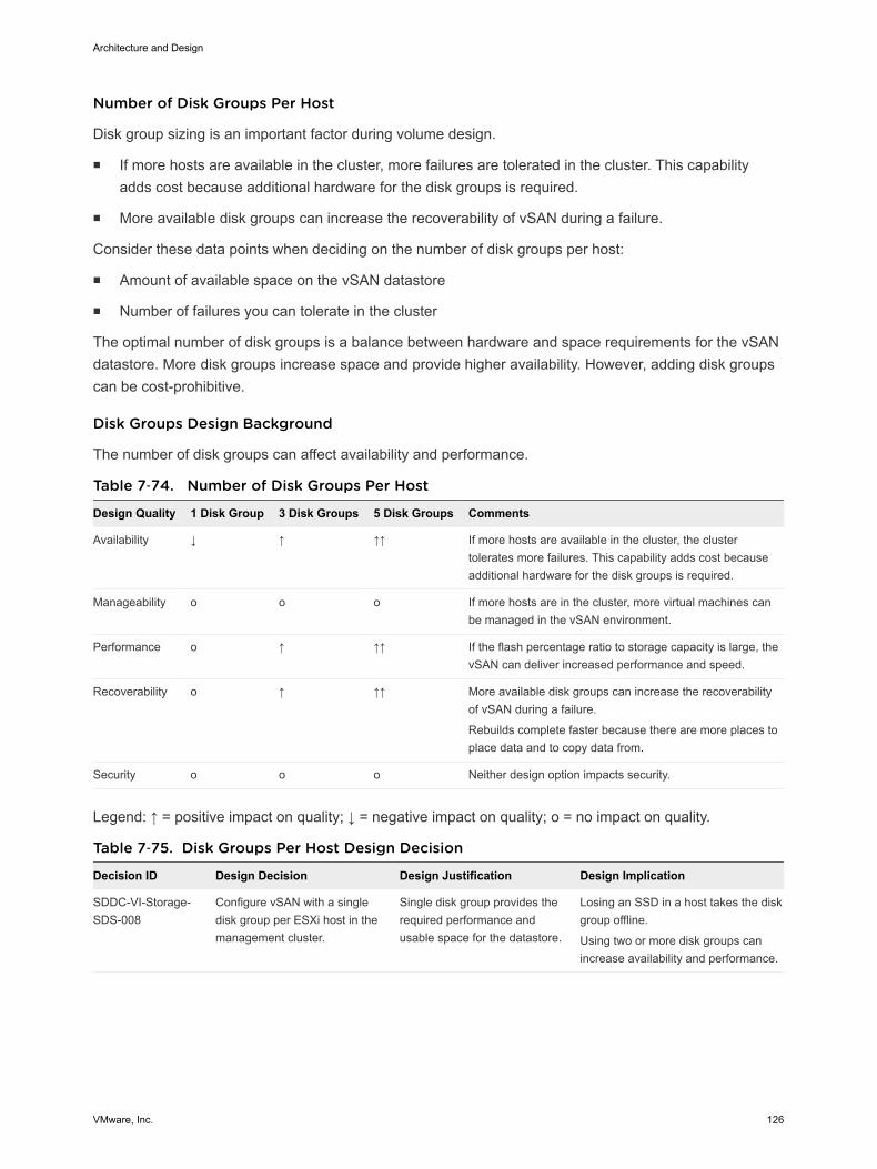
Number of Disk Groups Per Host
Disk group sizing is an important factor during volume design.
n If more hosts are available in the cluster, more failures are tolerated in the cluster. This capabilityadds cost because additional hardware for the disk groups is required.
n More available disk groups can increase the recoverability of vSAN during a failure.
Consider these data points when deciding on the number of disk groups per host:
n Amount of available space on the vSAN datastore
n Number of failures you can tolerate in the cluster
The optimal number of disk groups is a balance between hardware and space requirements for the vSANdatastore. More disk groups increase space and provide higher availability. However, adding disk groupscan be cost-prohibitive.
Disk Groups Design Background
The number of disk groups can affect availability and performance.
Table 7‑74. Number of Disk Groups Per Host
Design Quality 1 Disk Group 3 Disk Groups 5 Disk Groups Comments
Availability ↓ ↑ ↑↑ If more hosts are available in the cluster, the clustertolerates more failures. This capability adds cost becauseadditional hardware for the disk groups is required.
Manageability o o o If more hosts are in the cluster, more virtual machines canbe managed in the vSAN environment.
Performance o ↑ ↑↑ If the flash percentage ratio to storage capacity is large, thevSAN can deliver increased performance and speed.
Recoverability o ↑ ↑↑ More available disk groups can increase the recoverabilityof vSAN during a failure.
Rebuilds complete faster because there are more places toplace data and to copy data from.
Security o o o Neither design option impacts security.
Legend: ↑ = positive impact on quality; ↓ = negative impact on quality; o = no impact on quality.
Table 7‑75. Disk Groups Per Host Design Decision
Decision ID Design Decision Design Justification Design Implication
SDDC-VI-Storage-SDS-008
Configure vSAN with a singledisk group per ESXi host in themanagement cluster.
Single disk group provides therequired performance andusable space for the datastore.
Losing an SSD in a host takes the diskgroup offline.
Using two or more disk groups canincrease availability and performance.
Architecture and Design
VMware, Inc. 126
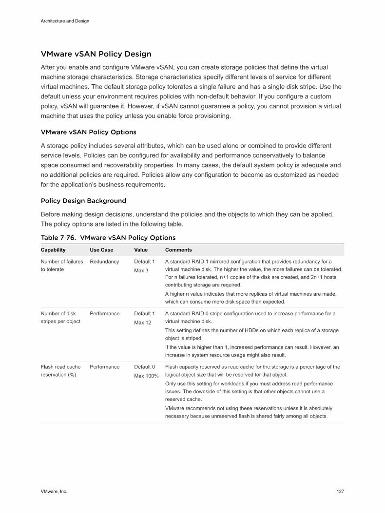
VMware vSAN Policy DesignAfter you enable and configure VMware vSAN, you can create storage policies that define the virtualmachine storage characteristics. Storage characteristics specify different levels of service for differentvirtual machines. The default storage policy tolerates a single failure and has a single disk stripe. Use thedefault unless your environment requires policies with non-default behavior. If you configure a custompolicy, vSAN will guarantee it. However, if vSAN cannot guarantee a policy, you cannot provision a virtualmachine that uses the policy unless you enable force provisioning.
VMware vSAN Policy Options
A storage policy includes several attributes, which can be used alone or combined to provide differentservice levels. Policies can be configured for availability and performance conservatively to balancespace consumed and recoverability properties. In many cases, the default system policy is adequate andno additional policies are required. Policies allow any configuration to become as customized as neededfor the application’s business requirements.
Policy Design Background
Before making design decisions, understand the policies and the objects to which they can be applied.The policy options are listed in the following table.
Table 7‑76. VMware vSAN Policy Options
Capability Use Case Value Comments
Number of failuresto tolerate
Redundancy Default 1
Max 3
A standard RAID 1 mirrored configuration that provides redundancy for avirtual machine disk. The higher the value, the more failures can be tolerated.For n failures tolerated, n+1 copies of the disk are created, and 2n+1 hostscontributing storage are required.
A higher n value indicates that more replicas of virtual machines are made,which can consume more disk space than expected.
Number of diskstripes per object
Performance Default 1
Max 12
A standard RAID 0 stripe configuration used to increase performance for avirtual machine disk.
This setting defines the number of HDDs on which each replica of a storageobject is striped.
If the value is higher than 1, increased performance can result. However, anincrease in system resource usage might also result.
Flash read cachereservation (%)
Performance Default 0
Max 100%
Flash capacity reserved as read cache for the storage is a percentage of thelogical object size that will be reserved for that object.
Only use this setting for workloads if you must address read performanceissues. The downside of this setting is that other objects cannot use areserved cache.
VMware recommends not using these reservations unless it is absolutelynecessary because unreserved flash is shared fairly among all objects.
Architecture and Design
VMware, Inc. 127
Table 7‑76. VMware vSAN Policy Options (Continued)
Capability Use Case Value Comments
Object spacereservation (%)
Thickprovisioning
Default 0
Max 100%
The percentage of the storage object that will be thick provisioned upon VMcreation. The remainder of the storage will be thin provisioned.
This setting is useful if a predictable amount of storage will always be filled byan object, cutting back on repeatable disk growth operations for all but new ornon-predictable storage use.
Force provisioning Override policy Default:
No
Force provisioning allows for provisioning to occur even if the currentlyavailable cluster resources cannot satisfy the current policy.
Force provisioning is useful in case of a planned expansion of the vSANcluster, during which provisioning of VMs must continue. VMware vSANautomatically tries to bring the object into compliance as resources becomeavailable.
By default, policies are configured based on application requirements. However, they are applieddifferently depending on the object.
Table 7‑77. Object Policy Defaults
Object Policy Comments
Virtual machine namespace Failures-to-Tolerate: 1 Configurable. Changes are not recommended.
Swap Failures-to-Tolerate: 1 Configurable. Changes are not recommended.
Virtual disk(s) User-Configured Storage Policy Can be any storage policy configured on the system.
Virtual disk snapshot(s) Uses virtual disk policy Same as virtual disk policy by default. Changes are notrecommended.
Note If you do not specify a user-configured policy, the default system policy of 1 failure to tolerate and 1disk stripe is used for virtual disk(s) and virtual disk snapshot(s). Policy defaults for the VM namespaceand swap are set statically and are not configurable to ensure appropriate protection for these criticalvirtual machine components. Policies must be configured based on the application’s businessrequirements. Policies give VMware vSAN its power because it can adjust how a disk performs on the flybased on the policies configured.
Policy Design Recommendations
Policy design starts with assessment of business needs and application requirements. Use cases forVMware vSAN must be assessed to determine the necessary policies. Start by assessing the followingapplication requirements:
n I/O performance and profile of your workloads on a per-virtual-disk basis
n Working sets of your workloads
n Hot-add of additional cache (requires repopulation of cache)
n Specific application best practice (such as block size)
Architecture and Design
VMware, Inc. 128
After assessment, configure the software-defined storage module policies for availability and performancein a conservative manner so that space consumed and recoverability properties are balanced. In manycases the default system policy is adequate and no additional policies are required unless specificrequirements for performance or availability exist.
Table 7‑78. Policy Design Decision
Decision ID Design Decision Design Justification Design Implication
SDDC-VI-Storage-SDS-009
Use the defaultVMware vSANstorage policy.
The default vSAN storage policy provides the level ofredundancy that is needed within the managementcluster. Additionally, using unique vSAN storagepolicies are not required as the default policy providesthe level of performance that is needed for theindividual management components.
Additional policies might beneeded if 3rd party VMs arehosted in these clusters becausetheir performance or availabilityrequirements might differ fromwhat the default VMware vSANpolicy supports.
SDDC-VI-Storage-SDS-010
Configure the virtualmachine swap fileas a sparse objectson VMware vSAN
Enabling this setting creates virtual swap files as asparse object on the vSAN datastore. Sparse virtualswap files will only consume capacity on vSAN asthey are accessed. The result can be significantly lessspace consumed on the vSAN datastore, providedvirtual machines do not experience memory overcommitment, requiring use of the virtual swap file.
Administrative overhead toenable the advanced setting onall ESXi hosts running VMwarevSAN.
NFS Storage DesignThis NFS design does not give specific vendor or array guidance. Consult your storage vendor for theconfiguration settings appropriate for your storage array.
NFS Storage ConceptsNFS (Network File System) presents file devices to an ESXi host for mounting over a network. The NFSserver or array makes its local file systems available to ESXi hosts. The ESXi hosts access the metadataand files on the NFS array or server using a RPC-based protocol. NFS is implemented using StandardNIC that is accessed using a VMkernel port (vmknic).
NFS Load BalancingNo load balancing is available for NFS/NAS on vSphere because it is based on single sessionconnections. You can configure aggregate bandwidth by creating multiple paths to the NAS array, and byaccessing some datastores via one path, and other datastores via another path. You can configure NICTeaming so that if one interface fails, another can take its place. However, these load balancingtechniques work only in case of a network failure and might not be able to handle error conditions on theNFS array or on the NFS server. The storage vendor is often the source for correct configuration andconfiguration maximums.
NFS VersionsvSphere is compatible with both NFS version 3 and version 4.1; however, not all features can be enabledwhen connecting to storage arrays that use NFS v4.1.
Architecture and Design
VMware, Inc. 129
Table 7‑79. NFS Version Design Decision
Decision ID Design Decision Design Justification Design Implication
SDDC-VI-Storage-NFS-001
Use NFS v3 for all NFSdatastores.
NFS v4.1 datastores are notsupported with Storage I/O Control.
NFS v3 does not supportKerberos authentication.
Storage AccessNFS v3 traffic is transmitted in an unencrypted format across the LAN. Therefore, best practice is to useNFS storage on trusted networks only and to isolate the traffic on dedicated VLANs.
Many NFS arrays have some built-in security, which enables them to control the IP addresses that canmount NFS exports. Best practice is to use this feature to determine which ESXi hosts can mount thevolumes that are being exported and have read/write access to those volumes. This prevents unapprovedhosts from mounting the NFS datastores.
ExportsAll NFS exports are shared directories that sit on top of a storage volume. These exports control theaccess between the endpoints (ESXi hosts) and the underlying storage system. Multiple exports can existon a single volume, with different access controls on each.
Export Size per Region Size
vRealize Log Insight Archive 1 TB
Table 7‑80. NFS Export Design Decisions
Decision ID Design Decision Design Justification Design Implication
SDDC-VI-Storage-NFS-002
Create 1 exports to support thevRealize Log Insight Archivemanagement components.
The storage requirements of thesemanagement components areseparate from the primarystorage.
You can add exports if youexpand the design.
SDDC-VI-Storage-NFS-004
For any export, limit access to only theapplication VMs or hosts requiring theability to mount the storage.
Limiting access helps ensure thesecurity of the underlying data.
Securing exportsindividually can introduceoperational overhead.
Architecture and Design
VMware, Inc. 130
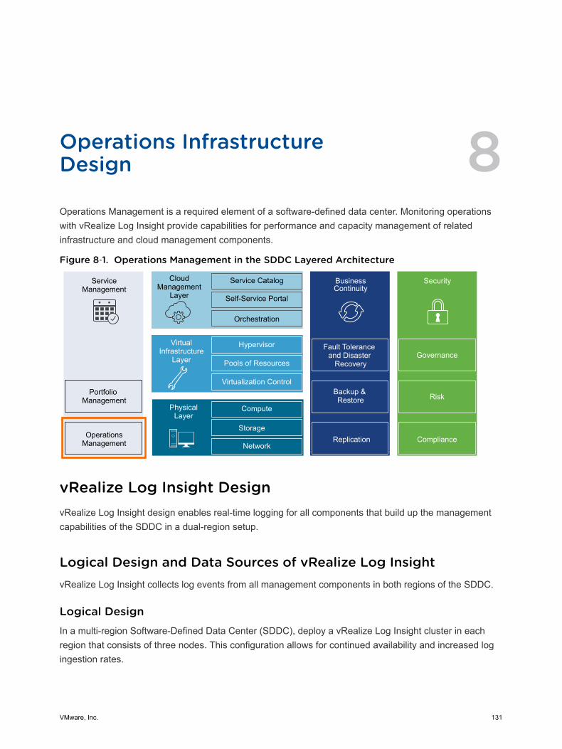
Operations InfrastructureDesign 8Operations Management is a required element of a software-defined data center. Monitoring operationswith vRealize Log Insight provide capabilities for performance and capacity management of relatedinfrastructure and cloud management components.
Figure 8‑1. Operations Management in the SDDC Layered Architecture
ServiceManagement
Portfolio Management
OperationsManagement
CloudManagement
Layer
Service Catalog
Self-Service Portal
Orchestration
BusinessContinuity
Fault Tolerance and Disaster
Recovery
Backup & Restore
Hypervisor
Pools of Resources
Virtualization Control
VirtualInfrastructure
Layer
Compute
Storage
Network
PhysicalLayer
Security
Replication Compliance
Risk
Governance
vRealize Log Insight DesignvRealize Log Insight design enables real-time logging for all components that build up the managementcapabilities of the SDDC in a dual-region setup.
Logical Design and Data Sources of vRealize Log InsightvRealize Log Insight collects log events from all management components in both regions of the SDDC.
Logical DesignIn a multi-region Software-Defined Data Center (SDDC), deploy a vRealize Log Insight cluster in eachregion that consists of three nodes. This configuration allows for continued availability and increased logingestion rates.
VMware, Inc. 131
Sources of Log DatavRealize Log Insight collects logs as to provide monitoring information about the SDDC from a centrallocation.
vRealize Log Insight collects log events from the following virtual infrastructure and cloud managementcomponents.
n Management pod
n Platform Services Controller
n vCenter Server
n ESXi hosts
n Shared edge and compute pod
n Platform Services Controller
n vCenter Server
n ESXi hosts
n NSX for vSphere for the management cluster and for the shared compute and edge cluster
n NSX Managers
n NSX Controller instances
n NSX Edge services gateway instances
n NSX distributed logical router instances
n NSX universal distributed logical router instances
n NSX distributed firewall ESXi kernel module
n vRealize Log Insight instance in the other region as a result of event forwarding
Node Configuration in vRealize Log InsightThe vRealize Log Insight cluster consists of one master node and two worker nodes behind a loadbalancer.
You enable the integrated load balancer (ILB) on the 3-node cluster so that all log sources can addressthe cluster by its ILB. By using the ILB, you need not reconfigure all log sources with a new destinationaddress in a future scale-out. Using the ILB also guarantees that vRealize Log Insight accepts allincoming ingestion traffic.
vRealize Log Insight users connect to vRealize Log Insight using the ILB address. They use the ILBaddress when using the Web user interface or API, and clients, and when ingesting logs via syslog or theIngestion API.
vRealize Log Insight cluster can scale out to 12 nodes, that is, 1 master and 11 worker nodes.
Architecture and Design
VMware, Inc. 132
Table 8‑1. Design Decisions about Node Configuration for vRealize Log Insight
Decision ID Design Decision Design Justification Design Implication
SDDC-OPS-LOG-001
Deploy vRealize Log Insightin a cluster configuration of3 nodes with an integratedload balancer: one masterand two worker nodes.
Using the integrated load balancer(ILB) has the following advantages:n Provides high availability.n Prevents a single point of failure.n Simplifies the Log Insight
deployment and subsequentintegration.
n Simplifies the Log Insight scale-outoperations reducing the need toreconfigure existing loggingsources
n You must deploy a minimum of 3medium nodes.
n You must size each node identically.n If the capacity requirements for your
vRealize Log Insight cluster grow,identical capacity must be added toeach node.
SDDC-OPS-LOG-002
Apply vSphere DistributedResource Scheduler (DRS)anti-affinity rules to thevRealize Log Insight clustercomponents.
Using DRS prevents the vRealize LogInsight nodes from running on thesame ESXi host and risking the highavailability of the cluster.
n You must perform additionalconfiguration to set up anti-affinityrules.
n You can put in maintenance modeonly a single ESXi host at a time inthe management cluster of four ESXihosts.
Sizing Compute and Storage Resources in vRealize Log InsightTo accommodate all log data from the products in the SDDC, you must size the compute resources andstorage for the Log Insight nodes properly.
By default, the vRealize Log Insight virtual appliance uses the predefined values for small configurations,which have 4 vCPUs, 8 GB of virtual memory, and 530.5 GB of disk space. vRealize Log Insight uses 100GB of the disk space to store raw data, index, metadata, and other information.
Sizing NodesSelect a size for the vRealize Log Insight nodes so as to collect and store log data from the SDDCmanagement components and tenant workloads according to the objectives of this design.
Table 8‑2. Compute Resources for a vRealize Log Insight Medium-Size Node
Attribute Specification
Appliance size Medium
Number of CPUs 8
Memory 16 GB
Disk Capacity 530.5 GB (490 GB for event storage)
IOPS 1,000 IOPS
Amount of processed log data when using log ingestion 75 GB/day of processing per node
Number of processed log messages 5,000 event/second of processing per node
Environment Up to 250 syslog connections per node
Architecture and Design
VMware, Inc. 133
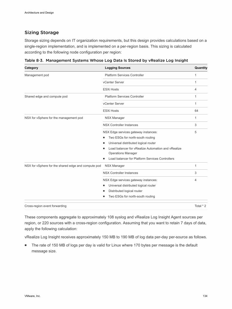
Sizing StorageStorage sizing depends on IT organization requirements, but this design provides calculations based on asingle-region implementation, and is implemented on a per-region basis. This sizing is calculatedaccording to the following node configuration per region:
Table 8‑3. Management Systems Whose Log Data Is Stored by vRealize Log Insight
Category Logging Sources Quantity
Management pod Platform Services Controller 1
vCenter Server 1
ESXi Hosts 4
Shared edge and compute pod Platform Services Controller 1
vCenter Server 1
ESXi Hosts 64
NSX for vSphere for the management pod NSX Manager 1
NSX Controller Instances 3
NSX Edge services gateway instances:n Two ESGs for north-south routingn Universal distributed logical routern Load balancer for vRealize Automation and vRealize
Operations Managern Load balancer for Platform Services Controllers
5
NSX for vSphere for the shared edge and compute pod NSX Manager 1
NSX Controller Instances 3
NSX Edge services gateway instances:n Universal distributed logical routern Distributed logical routern Two ESGs for north-south routing
4
Cross-region event forwarding Total * 2
These components aggregate to approximately 108 syslog and vRealize Log Insight Agent sources perregion, or 220 sources with a cross-region configuration. Assuming that you want to retain 7 days of data,apply the following calculation:
vRealize Log Insight receives approximately 150 MB to 190 MB of log data per-day per-source as follows.
n The rate of 150 MB of logs per day is valid for Linux where 170 bytes per message is the defaultmessage size.
Architecture and Design
VMware, Inc. 134
n The rate of 190 MB of logs per day is valid for Windows where 220 bytes per message is the defaultmessage size.
170 bytes per message * 10 messages per second * 86400 seconds per day = 150 MB of logs per-day per-
source (Linux)
220 bytes per message * 10 messages per second * 86400 seconds per day = 190 MB of logs per-day per-
source (Windows)
In this validated design, to simplify calculation, all calculations have been done using the large 220 bytesize which results in 190 MB of log data expected per-day per-source.
For 220 logging sources, at a basal rate of approximately 190 MB of logs that are ingested per-day per-source over 7 days, you need the following storage space:
Calculate the storage space required for a single day for log data using the following calculation:
220 sources * 190 MB of logs per-day per-source * 1e-9 GB per byte ≈ 42 GB disk space per-day
Based on the amount of data stored in a day, to size the appliance for 7 days of log retention, use thefollowing calculation:
(42 GB * 7 days) / 3 аppliances ≈ 100 GB log data per vRealize Log Insight node
100 GB * 1.7 indexing overhead ≈ 170 GB log data per vRealize Log Insight Node
Based on this example, the storage space that is allocated per medium-size vRealize Log Insight virtualappliance is enough to monitor the SDDC.
Consider the following approaches when you must increase the Log Insight capacity:
n If you must maintain a log data retention for more than 7 days in your SDDC, you might add morestorage per node by adding a new virtual hard disk. vRealize Log Insight supports virtual hard disks ofup to 2 TB. If you must add more than 2 TB to a virtual appliance, add another virtual hard disk.
When you add storage to increase the retention period, extend the storage for all virtual appliances.
When you add storage so that you can increase the retention period, extend the storage for all virtualappliances. To increase the storage, add new virtual hard disks only. Do not extend existing retentionvirtual disks. Once provisioned, do not reduce the size or remove virtual disks to avoid data loss.
n If you must monitor more components by using log ingestion and exceed the number of syslogconnections or ingestion limits defined in this design, you can do the following:
n Increase the size of the vRealize Log Insight node, to a medium or large deployment size asdefined in the vRealize Log Insight documentation.
n Deploy more vRealize Log Insight virtual appliances to scale your environment out. vRealize LogInsight can scale up to 12 nodes in an HA cluster.
Architecture and Design
VMware, Inc. 135
Table 8‑4. Design Decisions about the Compute Resources for the vRealize Log InsightNodes
Decision ID Design Decision Design Justification Design Implication
SDDC-OPS-LOG-003
Deploy vRealizeLog Insight nodesof medium size.
Accommodates the number of expected syslog and vRealizeLog Insight Agent connections from the following sources:n Management vCenter Server and Compute vCenter
Server, and connected Platform Services Controller pairn Management ESXi hosts, and shared edge and compute
ESXi hostsn Management and compute components for NSX for
vSpheren Cross-vRealize Log Insight cluster event forwarding.
These source approximately generate about 220 syslog andvRealize Log Insight Agent sources.
Using a medium-size appliances ensures that the storagespace for the vRealize Log Insight cluster is sufficient for 7days of data retention.
You must increase thesize of the nodes if youconfigure Log Insight tomonitor additional syslogsources.
Networking Design of vRealize Log InsightIf a storage solution other than vSAN is chosen, you must take into account that all the design,deployment, and day 2 guidance in the VMware Validated Design applies under the context of vSAN andadjust appropriately. Your storage design must match or exceed the capacity and performancecapabilities of the vSAN configuration in the designs.
Architecture and Design
VMware, Inc. 136
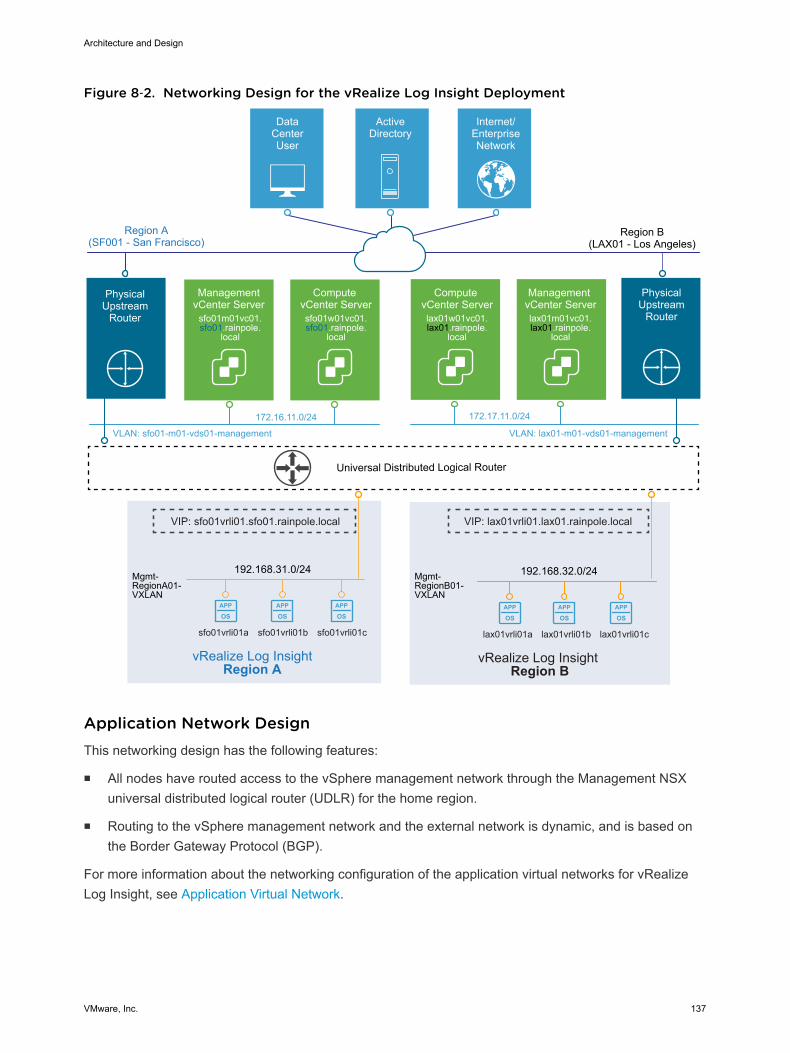
Figure 8‑2. Networking Design for the vRealize Log Insight Deployment
APP
OSAPP
OSAPP
OS
APP
OSAPP
OSAPP
OS
192.168.32.0/24
vRealize Log Insight Region B
192.168.31.0/24Mgmt-RegionA01-VXLAN
vRealize Log Insight Region A
Universal Distributed Logical Router
Mgmt-RegionB01-VXLAN
DataCenterUser
ActiveDirectory
Internet/EnterpriseNetwork
Region A(SF001 - San Francisco)
Management vCenter Serverlax01m01vc01.lax01.rainpole.
local
Compute vCenter Serverlax01w01vc01.lax01.rainpole.
local
VLAN: sfo01-m01-vds01-management
172.16.11.0/24
VLAN: lax01-m01-vds01-management
172.17.11.0/24
Management vCenter Server
sfo01m01vc01.sfo01.rainpole.
local
Compute vCenter Serversfo01w01vc01.sfo01.rainpole.
local
PhysicalUpstream
Router
Region B(LAX01 - Los Angeles)
PhysicalUpstream
Router
VIP: lax01vrli01.lax01.rainpole.local
lax01vrli01a lax01vrli01b lax01vrli01csfo01vrli01a sfo01vrli01b sfo01vrli01c
VIP: sfo01vrli01.sfo01.rainpole.local
Application Network DesignThis networking design has the following features:
n All nodes have routed access to the vSphere management network through the Management NSXuniversal distributed logical router (UDLR) for the home region.
n Routing to the vSphere management network and the external network is dynamic, and is based onthe Border Gateway Protocol (BGP).
For more information about the networking configuration of the application virtual networks for vRealizeLog Insight, see Application Virtual Network.
Architecture and Design
VMware, Inc. 137
Table 8‑5. Networking for vRealize Log Insight Design Decision
Decision ID Design Decision Design Justification Design Implication
SDDC-OPS-LOG-004
Deploy vRealize LogInsight on the region-specific applicationvirtual networks.
n Ensures centralized access to log dataper region if a cross-region networkoutage occurs.
n Co-locates log collection to the region-local SDDC applications using theregion-specific application virtualnetworks.
n Provides a consistent deploymentmodel for management applications.
n Interruption in the cross-regionnetwork can impact eventforwarding between the vRealizeLog Insight clusters and causegaps in log data.
n You must use NSX to support thisnetwork configuration.
IP Subnets for vRealize Log InsightYou can allocate the following example subnets to the vRealize Log Insight deployment.
Table 8‑6. IP Subnets in the Application Isolated Networks of vRealize Log Insight
vRealize Log Insight Cluster IP Subnet
Region A 192.168.31.0/24
Region B 192.168.32.0/24
DNS Names for vRealize Log InsightvRealize Log Insight node name resolution, including the load balancer virtual IP addresses (VIPs), usesa region-specific suffix, such as sfo01.rainpole.local or lax01.rainpole.local. The Log Insight componentsin both regions have the following node names.
Note The Region B (lax) information is included only in case you decide to deploy vRealize Log Insightin two regions.
Table 8‑7. DNS Names of the vRealize Log Insight Nodes
DNS Name Role Region
sfo01vrli01.sfo01.rainpole.local Log Insight ILB VIP Region A
sfo01vrli01a.sfo01.rainpole.local Master node Region A
sfo01vrli01b.sfo01.rainpole.local Worker node Region A
sfo01vrli01c.sfo01.rainpole.local Worker node Region A
sfo01vrli01x.sfo01.rainpole.local Additional worker nodes (not deployed) Region A
lax01vrli01.lax01.rainpole.local Log Insight ILB VIP Region B
lax01vrli01a.lax01.rainpole.local Master node Region B
lax01vrli01b.lax01.rainpole.local Worker node Region B
lax01vrli01c.lax01.rainpole.local Worker node Region B
lax01vrli01x.lax01.rainpole.local Additional worker nodes (not deployed) Region B
Architecture and Design
VMware, Inc. 138
Table 8‑8. Design Decisions about DNS Names for vRealize Log Insight
Decision ID Design Decision Design Justification Design Implication
SDDC-OPS-LOG-005
Configure forward and reverseDNS records for all vRealize LogInsight nodes and VIPs.
All nodes are accessible by usingfully-qualified domain namesinstead of by using IP addressesonly.
You must manually provide a DNSrecord for each node and VIP.
SDDC-OPS-LOG-006
If your design includesapplications that fail overbetween regions, use the FQDNof the vRealize Log InsightRegion A VIP when youconfigure logging.
Support logging when not allmanagement applications arefailed over to Region B. Forexample, only one application ismoved to Region B.
If an application is failed over toRegion B and the vRealize Log Insightcluster is no longer available in RegionA, update the A record on the childDNS server to point to the vRealizeLog Insight cluster in Region B.
Retention and Archiving in vRealize Log InsightConfigure archive and retention parameters of vRealize Log Insight according to the company policy forcompliance and governance.
vRealize Log Insight virtual appliances contain three default virtual disks and can use addition virtualdisks for storage.
Table 8‑9. Virtual Disk Configuration in the vRealize Log Insight Virtual Appliance
Hard Disk Size Usage
Hard disk 1 20 GB Root file system
Hard disk 2 510 GB for medium-size deployment Contains two partitions:n /storage/var System logsn /storage/core Storage for Collected logs.
Hard disk 3 512 MB First boot only
Calculate the storage space that is available for log data using the following equation:
/storage/core = hard disk 2 space - system logs space on hard disk 2
Based on the size of the default disk, the storage core is equal to 490 GB. If /storage/core is 490 GB,vRealize Log Insight can use 475 GB for retaining accessible logging data.
/storage/core = 510GB - 20 GB = 490 GB
Retention = /storage/core – 3% * /storage/core
Retention = 490 GB - 3% * 490 ≈ 475 GB disk space per vRLI appliance
Architecture and Design
VMware, Inc. 139
Retention time can be calculated using the following equations:
GB per vRLI Appliance per-day = (Amount in GB of disk space used per-day / Number of vRLI appliance)
* 1.7 indexing
Retention in Days = 475 GB disk space per vRLI appliance / GB per vRLI Appliance per-day
(42 GB of logging data ingested per-day / 3 vRLI appliance) * 1.7 indexing ≈ 24 GB per vRLI Appliance
per-day
475 GB disk space per vRLI appliance / 24 GB per vRLI Appliance per Day ≈ 20 days of retention
Configure a retention period of 7 days for the medium-size vRealize Log Insight appliance.
Table 8‑10. Retention Period for vRealize Log Insight Design Decision
Decision ID Design Decision Design Justification Design Implication
SDDC-OPS-LOG-007 Configure vRealize Log Insight toretain data for 7 days.
Accommodates logs from 220 syslog sourcesand vRealize Log Insight agents as per theSDDC design.
None
ArchivingYou configure vRealize Log Insight to archive log data only if you must retain logs for an extended periodfor compliance, auditability, or a customer-specific reason.
Attribute of LogArchiving Description
Archiving period vRealize Log Insight archives log messages as soon as possible. At the same time, the logs are retained onthe virtual appliance until the free local space is almost filled. Data exists on both the vRealize Log Insightappliance and the archive location for most of the retention period. The archiving period must be longer thanthe retention period.
Archive location The archive location must be on an NFS version 3 shared storage. The archive location must be availableand must have enough capacity to accommodate the archives.
Apply an archive policy of 90 days for the medium-size vRealize Log Insight appliance. The vRealize LogInsight appliance will use approximately 400 GB of shared storage calculated via the following:
(170 GB storage per vRLI Appliance * 3 vRLI Appliance) / 90 days Archiving Duration * 7 days Retention
Duration * 10% ≈ 400 GB
According to the business compliance regulations of your organization, these sizes might change.
Architecture and Design
VMware, Inc. 140
Table 8‑11. Log Archive Policy for vRealize Log Insight Design Decision
Decision ID Design Decision Design Justification Design Implication
SDDC-OPS-LOG-008
Provide 400 GB ofNFS version 3shared storage toeach vRealize LogInsight cluster.
Accommodates logarchiving from 220logging sources for 90days.
n You must manually maintain the vRealize Log Insightarchive blobs stored on the NFS store, selectively cleaningthe datastore as more space is required.
n You must increase the size of the NFS shared storage ifyou configure vRealize Log Insight to monitor more loggingsources or add more vRealize Log Insight workers areadded.
n You must enforce the archive policy directly on the sharedstorage.
n If the NFS mount does not have enough free space or isunavailable for a period greater than the retention period ofthe virtual appliance, vRealize Log Insight stops ingestingnew data until the NFS mount has enough free space,becomes available, or archiving is disabled.
Alerting in vRealize Log InsightvRealize Log Insight supports alerts that trigger notifications about its health.
Alert TypesThe following types of alerts exist in vRealize Log Insight:
System Alerts vRealize Log Insight generates notifications when an important systemevent occurs, for example, when the disk space is almost exhausted andvRealize Log Insight must start deleting or archiving old log files.
Content Pack Alerts Content packs contain default alerts that can be configured to sendnotifications. These alerts are specific to the content pack and are disabledby default.
User-Defined Alerts Administrators and users can define their own alerts based on dataingested by vRealize Log Insight.
vRealize Log Insight handles alerts in two ways:
n Send an e-mail over SMTP.
n Send to vRealize Operations Manager.
SMTP NotificationEnable e-mail notification for alerts in vRealize Log Insight.
Architecture and Design
VMware, Inc. 141
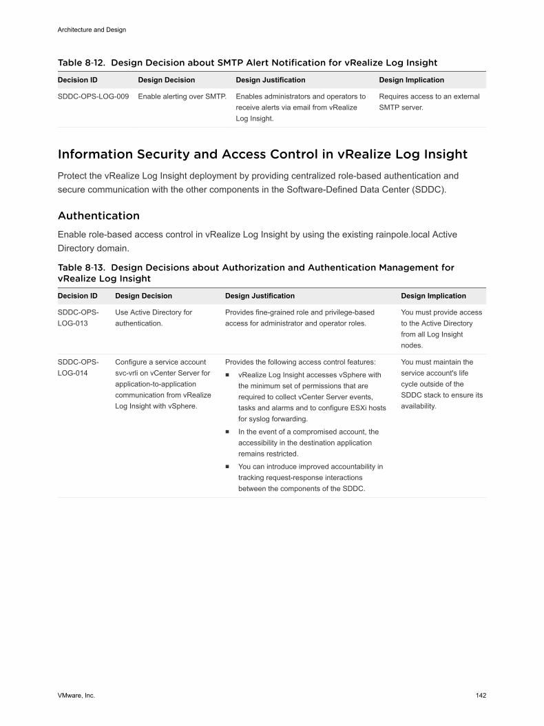
Table 8‑12. Design Decision about SMTP Alert Notification for vRealize Log Insight
Decision ID Design Decision Design Justification Design Implication
SDDC-OPS-LOG-009 Enable alerting over SMTP. Enables administrators and operators toreceive alerts via email from vRealizeLog Insight.
Requires access to an externalSMTP server.
Information Security and Access Control in vRealize Log InsightProtect the vRealize Log Insight deployment by providing centralized role-based authentication andsecure communication with the other components in the Software-Defined Data Center (SDDC).
AuthenticationEnable role-based access control in vRealize Log Insight by using the existing rainpole.local ActiveDirectory domain.
Table 8‑13. Design Decisions about Authorization and Authentication Management forvRealize Log Insight
Decision ID Design Decision Design Justification Design Implication
SDDC-OPS-LOG-013
Use Active Directory forauthentication.
Provides fine-grained role and privilege-basedaccess for administrator and operator roles.
You must provide accessto the Active Directoryfrom all Log Insightnodes.
SDDC-OPS-LOG-014
Configure a service accountsvc-vrli on vCenter Server forapplication-to-applicationcommunication from vRealizeLog Insight with vSphere.
Provides the following access control features:n vRealize Log Insight accesses vSphere with
the minimum set of permissions that arerequired to collect vCenter Server events,tasks and alarms and to configure ESXi hostsfor syslog forwarding.
n In the event of a compromised account, theaccessibility in the destination applicationremains restricted.
n You can introduce improved accountability intracking request-response interactionsbetween the components of the SDDC.
You must maintain theservice account's lifecycle outside of theSDDC stack to ensure itsavailability.
Architecture and Design
VMware, Inc. 142
Table 8‑13. Design Decisions about Authorization and Authentication Management forvRealize Log Insight (Continued)
Decision ID Design Decision Design Justification Design Implication
SDDC-OPS-LOG-015
Use global permissions whenyou create the svc-vrli serviceaccount in vCenter Server.
n Simplifies and standardizes the deployment ofthe service account across all vCenter Serversin the same vSphere domain.
n Provides a consistent authorization layer.
All vCenter Serverinstances must be in thesame vSphere domain.
SDDC-OPS-LOG-016
Configure a service accountsvc-vrli-vrops on vRealizeOperations Manager forapplication-to-applicationcommunication from vRealizeLog Insight for a two-waylaunch in context.
Provides the following access control features:n vRealize Log Insight and vRealize Operations
Manager access each other with the minimumset of required permissions.
n In the event of a compromised account, theaccessibility in the destination applicationremains restricted.
n You can introduce improved accountability intracking request-response interactionsbetween the components of the SDDC.
You must maintain theservice account's lifecycle outside of theSDDC stack to ensure itsavailability.
EncryptionReplace default self-signed certificates with a CA-signed certificate to provide secure access to thevRealize Log Insight Web user interface.
Table 8‑14. Design Decision about CA-Signed Certificates for vRealize Log Insight
Decision ID Design Decision Design Justification Design Implication
SDDC-OPS-LOG-017 Replace the default self-signed certificates with a CA-signed certificate.
Configuring a CA-signed certificateensures that all communication to theexternally facing Web UI is encrypted.
The administrator must haveaccess to a Public KeyInfrastructure (PKI) to acquirecertificates.
Configuration for Collecting Logs in vRealize Log InsightAs part of vRealize Log Insight configuration, you configure syslog and vRealize Log Insight agents.
Client applications can send logs to vRealize Log Insight in one of the following ways:
n Directly to vRealize Log Insight using the syslog TCP, syslog TCP over TLS/SSL, or syslog UDPprotocols
n By using a vRealize Log Insight Agent
n By using vRealize Log Insight to directly query the vSphere Web Server APIs
n By using a vRealize Log Insight user interface
The following design decisions result.
Note Breaks in the design decision numbering are intentional and help keep numbering in sync acrossdifferent VMware Validated Design use cases.
Architecture and Design
VMware, Inc. 143
Table 8‑15. Design Decisions about Direct Log Communication to vRealize Log Insight
Decision ID Design Decision Design Justification Design Implication
SDDC-OPS-LOG-018
Configure syslog sources andvRealize Log Insight Agents tosend log data directly to the virtualIP (VIP) address of the vRealizeLog Insight integrated loadbalancer (ILB).
n Allows for future scale-outwithout reconfiguring all logsources with a newdestination address.
n Simplifies the configuration oflog sources within the SDDC.
n You must configure the IntegratedLoad Balancer on the vRealize LogInsight cluster.
n You must configure logging sourcesto forward data to the vRealize LogInsight VIP.
SDDC-OPS-LOG-023
Configure the NSX for vSpherecomponents as direct syslogsources for vRealize Log Insightincluding:n NSX Managern NSX Controllersn NSX Edge services gateways
Simplifies configuration of logsources within the SDDC that aresyslog-capable.
n You must manually configure syslogsources to forward logs to thevRealize Log Insight VIP.
n Not all operating system-level eventsare forwarded to vRealize LogInsight.
SDDC-OPS-LOG-024
Configure vCenter ServerAppliance instances and PlatformServices Controller appliances asdirect syslog sources to send logdata directly to vRealize LogInsight.
Simplifies configuration for logsources that are syslog-capable.
n You must manually configure syslogsources to forward logs to thevRealize Log Insight VIP.
n Certain dashboards in vRealize LogInsight require the use of thevRealize Log Insight Agent forproper ingestion.
n Not all operating system level eventsare forwarded to vRealize LogInsight.
SDDC-OPS-LOG-025
Configure vRealize Log Insight toingest events, tasks, and alarmsfrom the Management vCenterServer and Compute vCenterServer instances.
Ensures that all tasks, events andalarms generated across allvCenter Server instances in aspecific region of the SDDC arecaptured and analyzed for theadministrator.
n You must create a service accounton vCenter Server to connectvRealize Log Insight for events,tasks, and alarms pulling.
n Configuring vSphere Integrationwithin vRealize Log Insight does notcapture events that occur on thePlatform Services Controller.
SDDC-OPS-LOG-026
Communicate with the syslogclients, such as ESXi, vCenterServer, NSX for vSphere, usingthe default syslog UDP protocol.
n Using the default UDP syslogprotocol simplifiesconfiguration for all syslogsources.
n UDP syslog protocol is themost common loggingprotocol that is availableacross products.
n UDP has a lowerperformance overheadcompared to TCP.
n If the network connection isinterrupted, the syslog traffic is lost.
n UDP syslog traffic is not secure.n UDP syslog protocol does not
support reliability and retrymechanisms.
Architecture and Design
VMware, Inc. 144
Table 8‑15. Design Decisions about Direct Log Communication to vRealize Log Insight(Continued)
Decision ID Design Decision Design Justification Design Implication
SDDC-OPS-LOG-027
Include the syslog configuration forvRealize Log Insight in the hostprofile for the following clusters:n Management clustern Shared edge and compute
clustern Any additional compute cluster
Simplifies the configuration of thehosts in the cluster and ensuresthat settings are uniform acrossthe cluster.
Every time you make an authorizedchange to a host regarding the syslogconfiguration you must update the hostprofile to reflect the change or the statuswill show non-compliant.
SDDC-OPS-LOG-028
Do not configure vRealize LogInsight to automatically update alldeployed agents.
Manually install updated versionsof the Log Insight agents for eachof the specified componentswithin the SDDC for precisemaintenance.
You must manually maintain thevRealize Log Insight agents on each ofthe SDDC components.
Time Synchronization in vRealize Log InsightTime synchronization is critical for the core functionality of vRealize Log Insight. By default, vRealize LogInsight synchronizes time with a pre-defined list of public NTP servers.
NTP ConfigurationConfigure consistent NTP sources on all systems that send log data (vCenter Server, ESXi, vRealizeOperation Manager). See Time Synchronization in the VMware Validated Design Planning andPreparation documentation.
Table 8‑16. Design Decision about Time Synchronization for vRealize Log Insight
Decision ID Design Decision Design Justification Design Implication
SDDC-OPS-LOG-029 Configure consistent NTP sources on allvirtual infrastructure and cloudmanagement applications for correct loganalysis in vRealize Log Insight.
Guarantees accurate logtimestamps.
Requires that all applicationssynchronize time to the sameNTP time source.
Event Forwarding Between Regions with vRealize Log InsightvRealize Log Insight supports event forwarding to other clusters and standalone instances. Whileforwarding events, the vRealize Log Insight instance still ingests, stores, and archives events locally.
You forward syslog data in vRealize Log Insight by using the Ingestion API or a native syslogimplementation.
The vRealize Log Insight Ingestion API uses TCP communication. In contrast to syslog, the forwardingmodule supports the following features for the Ingestion API:
n Forwarding to other vRealize Log Insight instances
n Both structured and unstructured data, that is, multi-line messages
Architecture and Design
VMware, Inc. 145
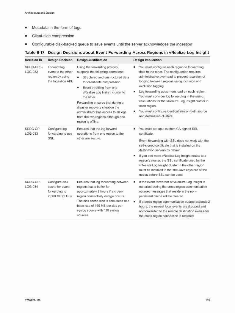
n Metadata in the form of tags
n Client-side compression
n Configurable disk-backed queue to save events until the server acknowledges the ingestion
Table 8‑17. Design Decisions about Event Forwarding Across Regions in vRealize Log Insight
Decision ID Design Decision Design Justification Design Implication
SDDC-OPS-LOG-032
Forward logevent to the otherregion by usingthe Ingestion API.
Using the forwarding protocolsupports the following operations:n Structured and unstructured data
for client-side compressionn Event throttling from one
vRealize Log Insight cluster tothe other.
Forwarding ensures that during adisaster recovery situation theadministrator has access to all logsfrom the two regions although oneregion is offline.
n You must configure each region to forward logdata to the other. The configuration requiresadministrative overhead to prevent recursion oflogging between regions using inclusion andexclusion tagging.
n Log forwarding adds more load on each region.You must consider log forwarding in the sizingcalculations for the vRealize Log Insight cluster ineach region.
n You must configure identical size on both sourceand destination clusters.
SDDC-OP-LOG-033
Configure logforwarding to useSSL.
Ensures that the log forwardoperations from one region to theother are secure.
n You must set up a custom CA-signed SSLcertificate.
Event forwarding with SSL does not work with theself-signed certificate that is installed on thedestination servers by default.
n If you add more vRealize Log Insight nodes to aregion's cluster, the SSL certificate used by thevRealize Log Insight cluster in the other regionmust be installed in that the Java keystore of thenodes before SSL can be used.
SDDC-OP-LOG-034
Configure diskcache for eventforwarding to2,000 MB (2 GB).
Ensures that log forwarding betweenregions has a buffer forapproximately 2 hours if a cross-region connectivity outage occurs.The disk cache size is calculated at abase rate of 150 MB per day persyslog source with 110 syslogsources.
n If the event forwarder of vRealize Log Insight isrestarted during the cross-region communicationoutage, messages that reside in the non-persistent cache will be cleared.
n If a cross-region communication outage exceeds 2hours, the newest local events are dropped andnot forwarded to the remote destination even afterthe cross-region connection is restored.
Architecture and Design
VMware, Inc. 146