Embed Size (px)
Citation preview
Umicore Marketing Services U.K. Four Rivers House,
Fentiman Walk Hertford, Herts, SG14 1DB
VM ZINC®: standing seamGuidelines for specification and installation
Junglim Architecture - QUARTZ-ZINC®
Roofing and cladding system in VM ZINC®
Roofs from a 3° pitch and facades
Freedom with shape and appearance
A choice of “ventilated” or “warm” roofing systems
This document applies exclusively to the specification and installation of the designated products
or systems on building sites in United Kingdom and the Republic of Ireland.
A Umicore brand

2
Standing Seam - ContentsVM ZINC natural and recyclableSurface appearancesWhat is standing seam?Types and areas of applications
Standing seam roofing, warm roof on mineral wool or PIRFixing clipsExamples of details: junction gutter, box gutter, verges, ridge/hip, valley detail, mansard, junction skylight and junction with chimmey
Standing seam roofing, warm roof on composite panelsFixing clipsExamples of details: junction gutter, box gutter, verges, ridge/hip, valley detail, mansard, junction skylight and junction with chimmey
Standing seam roofing, warm roof on cellular glassFixing clipsExamples of details: junction gutter, box gutter, verges, ridge/hip, valley detail, mansard, junction skylight and junction with chimmey
Standing seam roofing, ventilated roof on incompatible supportFixing clipsExamples of details: junction gutter, box gutter, verges, ventilated ridge/hip, valley detail, mansard, junction skylight and junction with chimmey
Standing seam roofing, ventilated roof on roof boardingFixing clipsExamples of details: junction gutter, box gutter, verges, ventilated ridge/hip, valley detail, mansard, junction skylight and junction with chimmey
Standing seam roofing, example very low pitchStanding seam roofing, specific applications
Standing seam facade, ventilated cladding, horizontal panels installed on boardingStanding seam facade, ventilated cladding, vertical panels installed on boarding
Standing seam - System installationExpansion of VM ZINC® - layoutMeasuring for and ordering profiled panels - maximum length of panelsTransportation, storage, installing and working VM ZINC®
Preparation and fixing of the top of the panels3 stage installation of the panels1. Laying the panel on the structure2. Installation of clips3. Preparation of the panels for crimpingCrimping
Standing seam facade - Installation of the system
Removing the protective film and moving around on the VM ZINC®
Appendix 1 - Junctions at the foot of the pitchAppendix 2 - Verge flashingAppendix 3 and 4 - Flashings and forbidden contactsAppendix 5 - Ventilation of VM ZINC® roofing and claddingAppendix 6 - Compatibility of VM ZINC® with wood, wood derivates, glues and mastics
3 .............................4 .............................5 ..............................6 and 7 ..................
8 .............................10 ...........................11 to 17 .................
18 ...........................20 ...........................21 to 27 .................
28 ...........................30 ...........................31 to 37 .................
38 ...........................40 ...........................41 to 47 .................
48 ...........................50 ...........................51 to 57 .................
58 ...........................59 ...........................
60 to 62 .................63 to 65 .................
66 ...........................67 ...........................68 ...........................69 ...........................
69 ...........................70 ...........................71 ...........................72 to 73 .................
74 ...........................
75 ...........................
76 ...........................77 ...........................78 ...........................79 ...........................80 to 81 .................
3
VM ZINC®
• is the brand name of rolled zinc products, transformed, produced
and sold by Umicore.
• conforms to the EN 988.
• is a 99.995% electrolytic zinc, to which very small quantities of
copper and titanium are added.
Physical properties of VM ZINC®
Density: 7.18+ 0.02 g/cm3.
Linear expansion: 0.022 mm per m and per °C in the direction of
rolling.
VM ZINC® - natural and recyclable
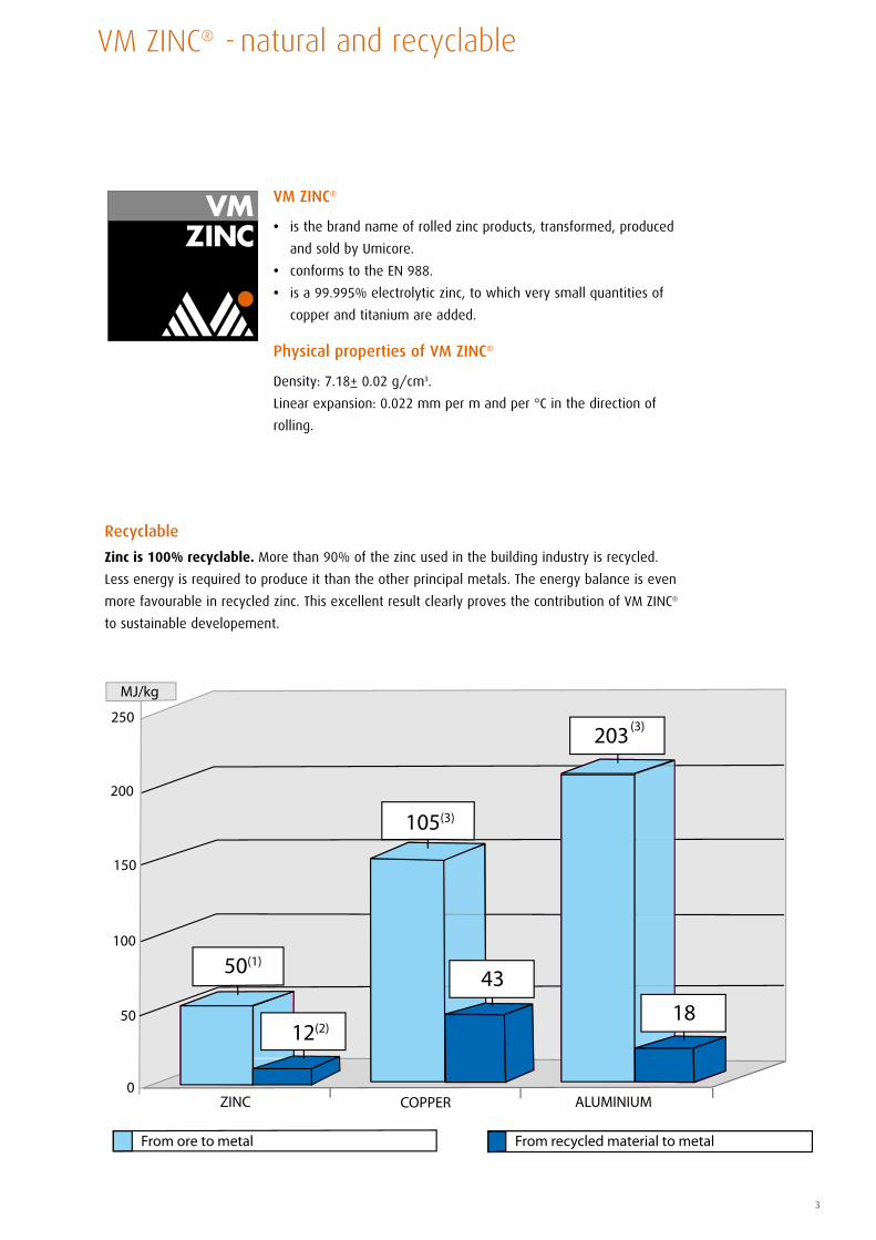
Recyclable
Zinc is 100% recyclable. More than 90% of the zinc used in the building industry is recycled.
Less energy is required to produce it than the other principal metals. The energy balance is even
more favourable in recycled zinc. This excellent result clearly proves the contribution of VM ZINC®
to sustainable developement.
150
100
50
0ZINC COPPER ALUMINIUM
200
250
MJ/kg
18
43
203(3)
105(3)
12(2)
50(1)
From ore to metal From recycled material to metal
4
Natural VM ZINC®
has a shiny metallic appearance when
new and develops a patina naturally
over time.
Thus it gradually takes on a uniform matt
grey appearance.
QUARTZ-ZINC®
offers an appearance and texture close
to the patina developed by natural
VM ZINC®.
The grey tones of QUARTZ-ZINC® and
its structural flexibility bring out the
character of a building from the outset.
Appreciated for refurbishment, its
natural-looking colour blends well with
existing construction materials.
The coating and pigments
do not in any way alter the
environmental properties of
pre-weathered VM ZINC®.
Moreover, the coating does not
contain chromate development.
Bilacquered VM ZINC®
6 colours are available: stone
white, sky blue, copper green,
autumn brown, slate grey and
Macao brown. For non standard
colours, please contact us.
VM ZINC®
surface appearances
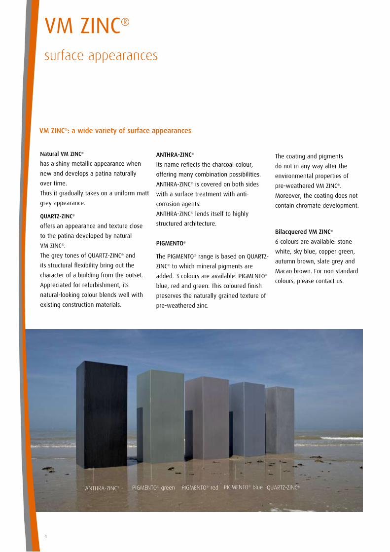
VM ZINC®: a wide variety of surface appearances
ANTHRA-ZINC® QUARTZ-ZINC®PIGMENTO® green PIGMENTO® red PIGMENTO® blue
ANTHRA-ZINC®
Its name reflects the charcoal colour,
offering many combination possibilities.
ANTHRA-ZINC® is covered on both sides
with a surface treatment with anti-
corrosion agents.
ANTHRA-ZINC® lends itself to highly
structured architecture.
PIGMENTO®
The PIGMENTO® range is based on QUARTZ-
ZINC® to which mineral pigments are
added. 3 colours are available: PIGMENTO®
blue, red and green. This coloured finish
preserves the naturally grained texture of
pre-weathered zinc.
5
The low height of the seams (25 mm
standard) and the 600 mm spacing
between joints give the roof a light,
harmonious appearance.
Moreover, any non-standard width
between 60 and 600 mm can be
produced.
Standing seam roofs or cladding should
only be installed by properly trained and
equipped professionals.
Thus the fixing clips for panels
and flashings never penetrate
the material and therefore do
not damage the appearance or
waterproofing.
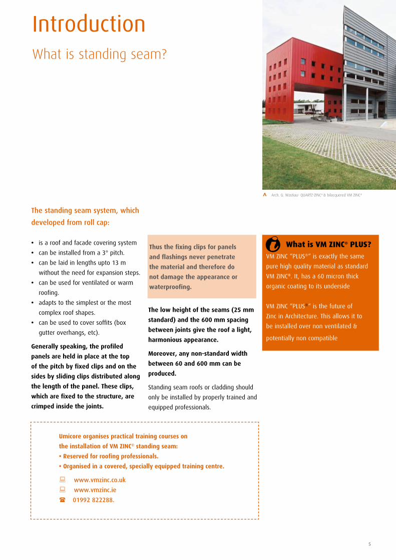
The standing seam system, which
developed from roll cap:
• is a roof and facade covering system
• can be installed from a 3° pitch.
• can be laid in lengths upto 13 m
without the need for expansion steps.
• can be used for ventilated or warm
roofing.
• adapts to the simplest or the most
complex roof shapes.
• can be used to cover soffits (box
gutter overhangs, etc).
Generally speaking, the profiled
panels are held in place at the top
of the pitch by fixed clips and on the
sides by sliding clips distributed along
the length of the panel. These clips,
which are fixed to the structure, are
crimped inside the joints.
VM ZINC “PLUS®“ is exactly the same
pure high quality material as standard
VM ZINC®. It, has a 60 micron thick
organic coating to its underside
VM ZINC “PLUS®“ is the future of
Zinc in Architecture. This allows it to
be installed over non ventilated &
potentially non compatible substrates.
Introduction What is standing seam?
> Arch. G. Wastiau- QUARTZ-ZINC® & bilacquered VM ZINC®
What is VM ZINC® PLUS?
Umicore organises practical training courses on
the installation of VM ZINC® standing seam:
• Reserved for roofing professionals.
• Organised in a covered, specially equipped training centre.
: www.vmzinc.co.uk
: www.vmzinc.ie
( 01992 822288.

6
Standing SeamTypes of application
Ventilated roof on roof boarding: VM ZINC® roof with ventilated underside. This ventilation
consists of an air space where the C02 in the air allows
the VM ZINC® to develop a natural patina on the underside.
This ventilated air space, with openings at the bottom and
top of the roof is absolutely necessary to guarantee the
durability of VM ZINC® (cf appendix 5 page 79).
Ventilated roof on incompatible support: In this application the underside of the metal is
unventilated and therefore the use of VM ZINC® PLUS
with an already protected underside is obligatory.
• Easy installation
• Can be used to cover complex shapes
• Classes of internal humidity load: 1 to 4
• Very competitive price
• Classes of internal humidity load:
1 to 4
VM ZINC® PLUS on composite panels
• Very competitive price
• Classes of internal humidity load:
1 to 4
VM ZINC® PLUS on mineral wool or PIR
• Very competitive price
• Classes of internal humidity load:
1 to 4
VM ZINC® PLUS on cellular glass
• Non - penetrating fastening
• Classes of internal humidity load:
1 to 5
Warm roof: VM ZINC® roofing is fixed directly on the insulating material.
The underside of the metal is unventilated and therefore the use of VM ZINC® PLUS with an already protected
underside is obligatory.
7
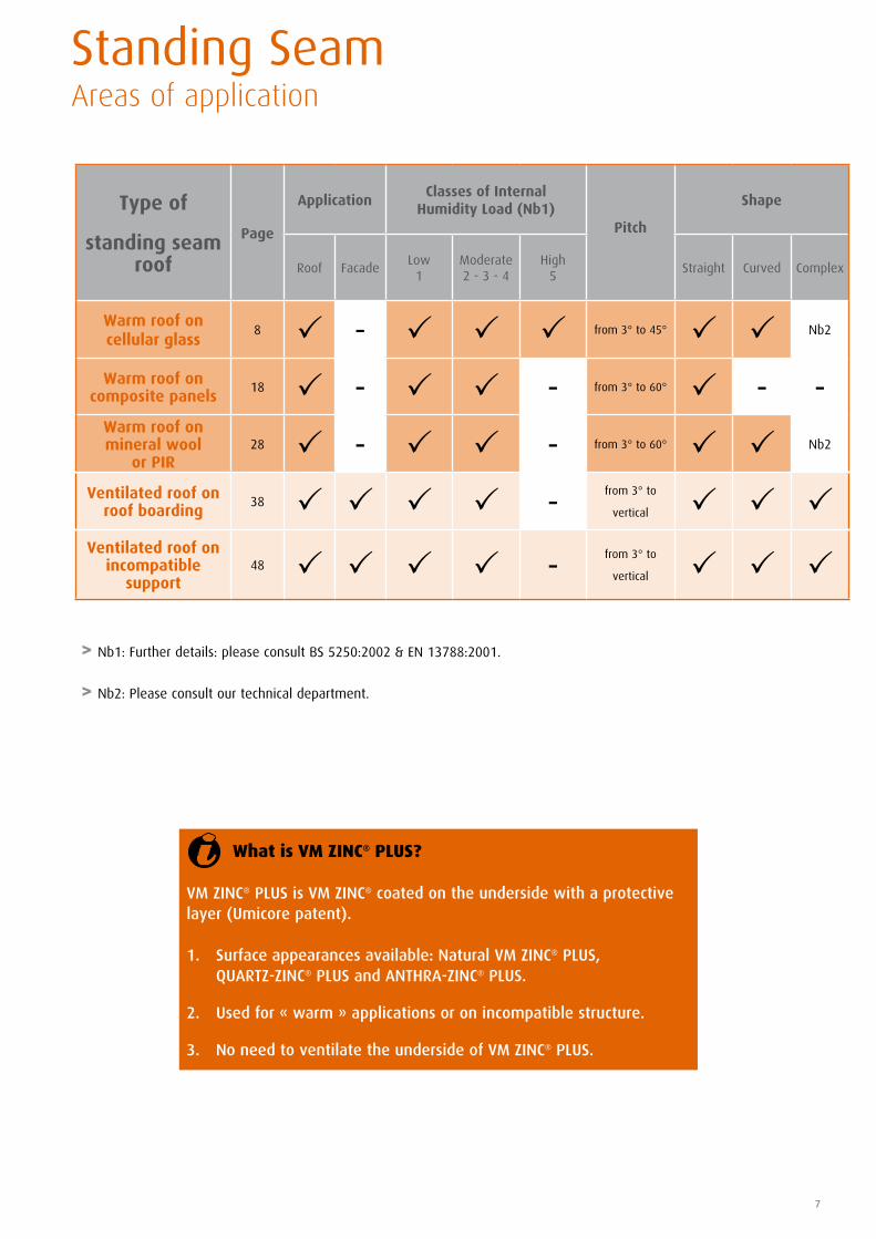
Standing SeamAreas of application
> Nb1: Further details: please consult BS 5250:2002 & EN 13788:2001.
> Nb2: Please consult our technical department.
Type of
standing seam roof
Page
ApplicationClasses of Internal
Humidity Load (Nb1)Pitch
Shape
Roof FacadeLow
1Moderate2 - 3 - 4
High5
Straight Curved Complex
Warm roof on cellular glass
8 P - P P P from 3° to 45° P P Nb2
Warm roof on composite panels
18 P - P P - from 3° to 60° P - -Warm roof on mineral wool
or PIR28 P - P P - from 3° to 60° P P Nb2
Ventilated roof on roof boarding
38 P P P P -from 3° to
vertical P P PVentilated roof on
incompatible support
48 P P P P -from 3° to
vertical P P P
What is VM ZINC® PLUS?
VM ZINC® PLUS is VM ZINC® coated on the underside with a protective layer (Umicore patent).
1. Surface appearances available: Natural VM ZINC® PLUS, QUARTZ-ZINC® PLUS and ANTHRA-ZINC® PLUS.
2. Used for « warm » applications or on incompatible structure.
3. No need to ventilate the underside of VM ZINC® PLUS.
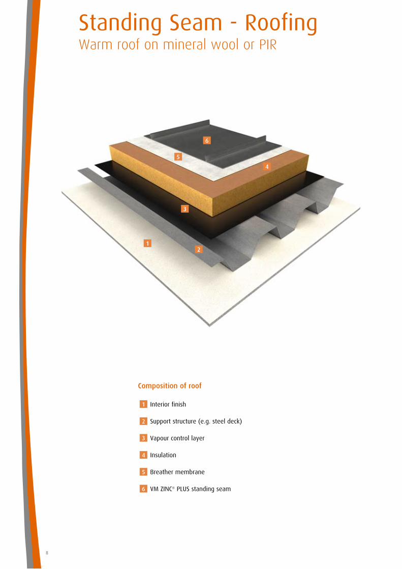
Standing Seam - RoofingWarm roof on mineral wool or PIR
8
Composition of roof
Interior finish
Support structure (e.g. steel deck)
Vapour control layer
Insulation
Breather membrane
VM ZINC® PLUS standing seam
1
1
2
3
4
5
6
2
3
4
5
6
9
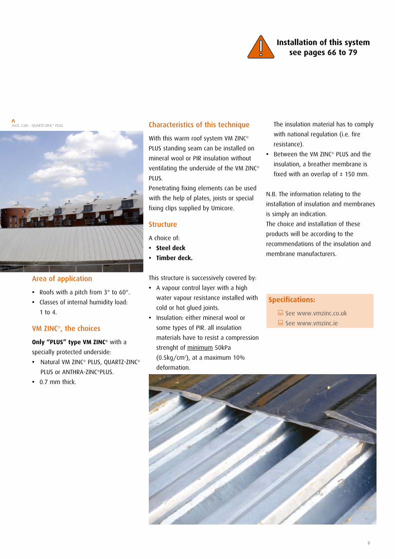
Characteristics of this technique
With this warm roof system VM ZINC®
PLUS standing seam can be installed on
mineral wool or PIR insulation without
ventilating the underside of the VM ZINC®
PLUS.
Penetrating fixing elements can be used
with the help of plates, joists or special
fixing clips supplied by Umicore.
Structure
A choice of:
• Steel deck
• Timber deck.
This structure is successively covered by:
• A vapour control layer with a high
water vapour resistance installed with
cold or hot glued joints.
• Insulation: either mineral wool or
some types of PIR. all insulation
materials have to resist a compression
strenght of minimum 50kPa
(0.5kg/cm2), at a maximum 10%
deformation.
Area of application
• Roofs with a pitch from 3° to 60°.
• Classes of internal humidity load:
1 to 4.
VM ZINC®, the choices
Only “PLUS” type VM ZINC® with a
specially protected underside:
• Natural VM ZINC® PLUS, QUARTZ-ZINC®
PLUS or ANTHRA-ZINC®PLUS.
• 0.7 mm thick.
The insulation material has to comply
with national regulation (i.e. fire
resistance).
• Between the VM ZINC® PLUS and the
insulation, a breather membrane is
fixed with an overlap of ± 150 mm.
N.B. The information relating to the
installation of insulation and membranes
is simply an indication.
The choice and installation of these
products will be according to the
recommendations of the insulation and
membrane manufacturers.
Arch. L3M - QUARTZ-ZINC® PLUS>
Installation of this system see pages 66 to 79
Specifications:
: See www.vmzinc.co.uk
: See www.vmzinc.ie
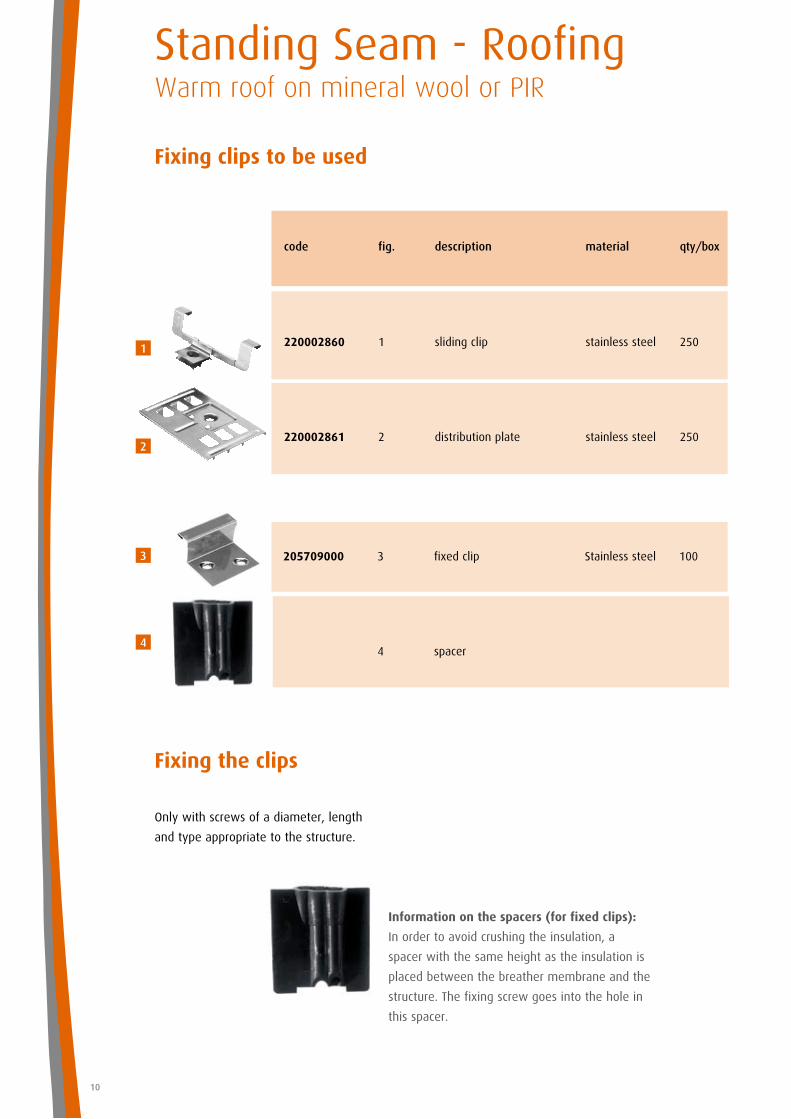
205709000 3 fixed clip Stainless steel 100
4 spacer
Information on the spacers (for fixed clips):
In order to avoid crushing the insulation, a
spacer with the same height as the insulation is
placed between the breather membrane and the
structure. The fixing screw goes into the hole in
this spacer.
Fixing clips to be used
Fixing the clips
Only with screws of a diameter, length
and type appropriate to the structure.
Standing Seam - RoofingWarm roof on mineral wool or PIR
10
code fig. description material qty/box
220002860 1 sliding clip stainless steel 250
220002861 2 distribution plate stainless steel 250
1
2
3
4
pitch min. 1°
pitch min. 1°
11
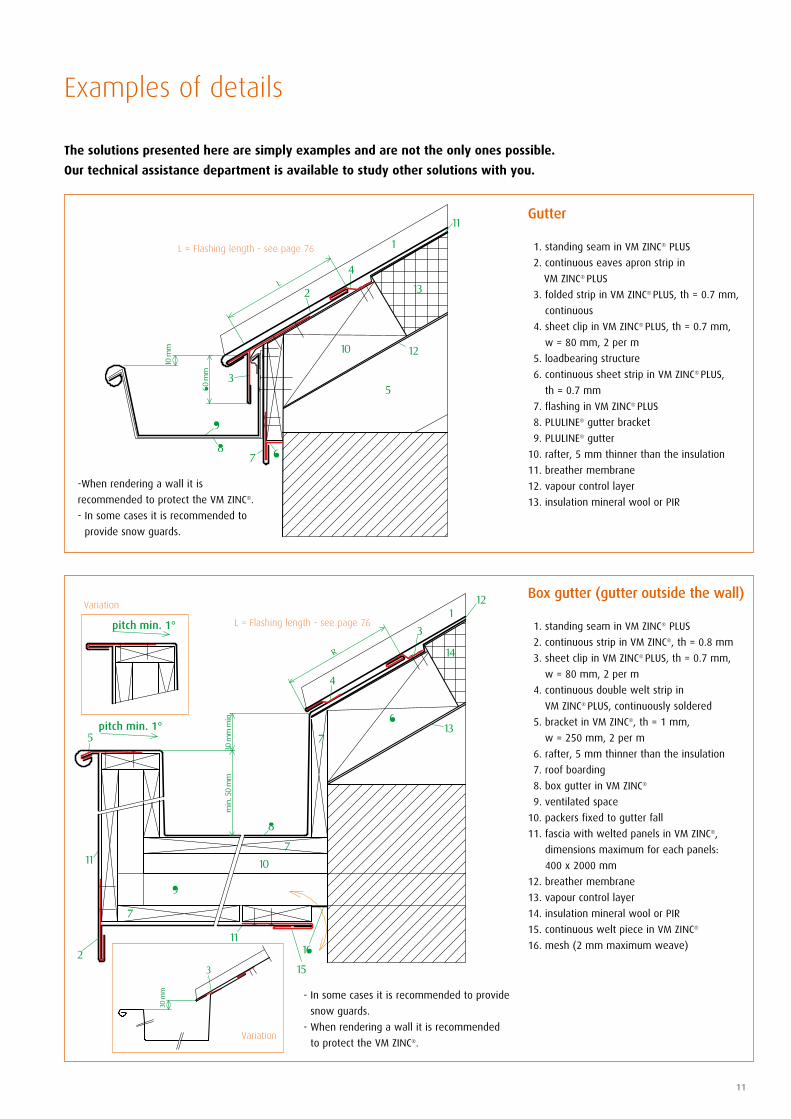
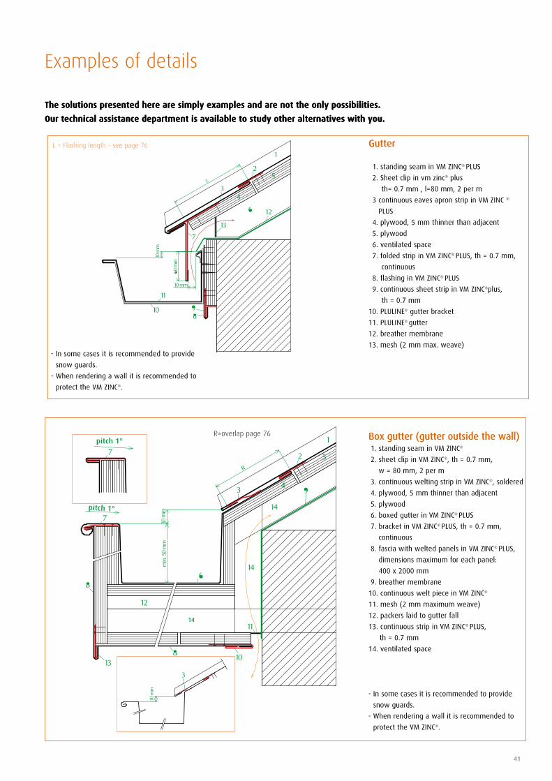
The solutions presented here are simply examples and are not the only ones possible.
Our technical assistance department is available to study other solutions with you.
Examples of details
Gutter
1. standing seam in VM ZINC® PLUS
2. continuous eaves apron strip in
VM ZINC® PLUS
3. folded strip in VM ZINC® PLUS, th = 0.7 mm,
continuous
4. sheet clip in VM ZINC® PLUS, th = 0.7 mm,
w = 80 mm, 2 per m
5. loadbearing structure
6. continuous sheet strip in VM ZINC® PLUS,
th = 0.7 mm
7. flashing in VM ZINC® PLUS
8. PLULINE® gutter bracket
9. PLULINE® gutter
10. rafter, 5 mm thinner than the insulation
11. breather membrane
12. vapour control layer
13. insulation mineral wool or PIR
L = Flashing length - see page 76
Box gutter (gutter outside the wall)
1. standing seam in VM ZINC® PLUS
2. continuous strip in VM ZINC®, th = 0.8 mm
3. sheet clip in VM ZINC® PLUS, th = 0.7 mm,
w = 80 mm, 2 per m
4. continuous double welt strip in
VM ZINC® PLUS, continuously soldered
5. bracket in VM ZINC®, th = 1 mm,
w = 250 mm, 2 per m
6. rafter, 5 mm thinner than the insulation
7. roof boarding
8. box gutter in VM ZINC®
9. ventilated space
10. packers fixed to gutter fall
11. fascia with welted panels in VM ZINC®,
dimensions maximum for each panels:
400 x 2000 mm
12. breather membrane
13. vapour control layer
14. insulation mineral wool or PIR
15. continuous welt piece in VM ZINC®
16. mesh (2 mm maximum weave)
- In some cases it is recommended to provide
snow guards.
- When rendering a wall it is recommended
to protect the VM ZINC®.
L = Flashing length - see page 76
-When rendering a wall it is
recommended to protect the VM ZINC®.
- In some cases it is recommended to
provide snow guards.
Variation
Variation
slope min. 3°
pitch min. 1°
pitch min. 1°
Standing Seam - RoofingWarm roof on mineral wool or PIR
12
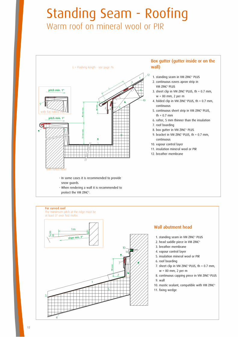
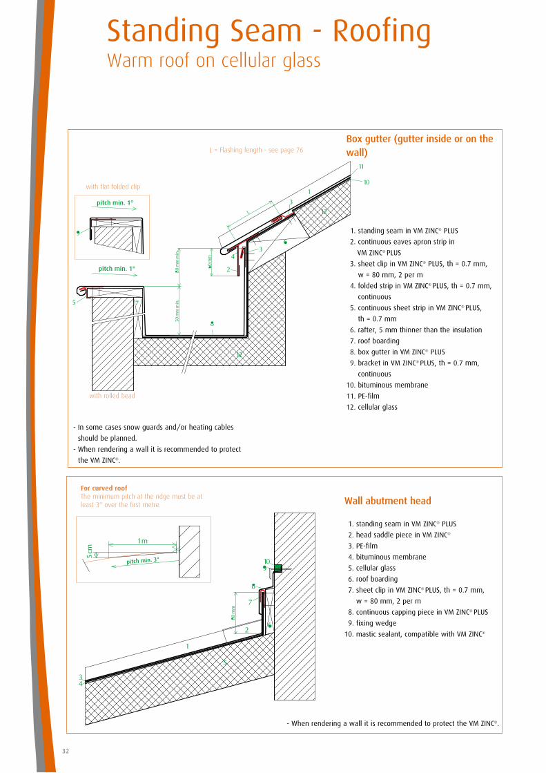
Wall abutment head
1. standing seam in VM ZINC® PLUS
2. head saddle piece in VM ZINC®
3. breather membrane
4. vapour control layer
5. insulation mineral wool or PIR
6. roof boarding
7. sheet clip in VM ZINC® PLUS, th = 0.7 mm,
w = 80 mm, 2 per m
8. continuous capping piece in VM ZINC® PLUS
9. wall
10. mastic sealant, compatible with VM ZINC®
11. fixing wedge
Box gutter (gutter inside or on the wall)
1. standing seam in VM ZINC® PLUS
2. continuous eaves apron strip in
VM ZINC® PLUS
3. sheet clip in VM ZINC® PLUS, th = 0.7 mm,
w = 80 mm, 2 per m
4. folded clip in VM ZINC® PLUS, th = 0.7 mm,
continuous
5. continuous sheet strip in VM ZINC® PLUS,
th = 0.7 mm
6. rafter, 5 mm thinner than the insulation
7. roof boarding
8. box gutter in VM ZINC® PLUS
9. bracket in VM ZINC® PLUS, th = 0.7 mm,
continuous
10. vapour control layer
11. insulation mineral wool or PIR
12. breather membrane
- In some cases it is recommended to provide
snow guards.
- When rendering a wall it is recommended to
protect the VM ZINC®.
L = Flashing length - see page 76
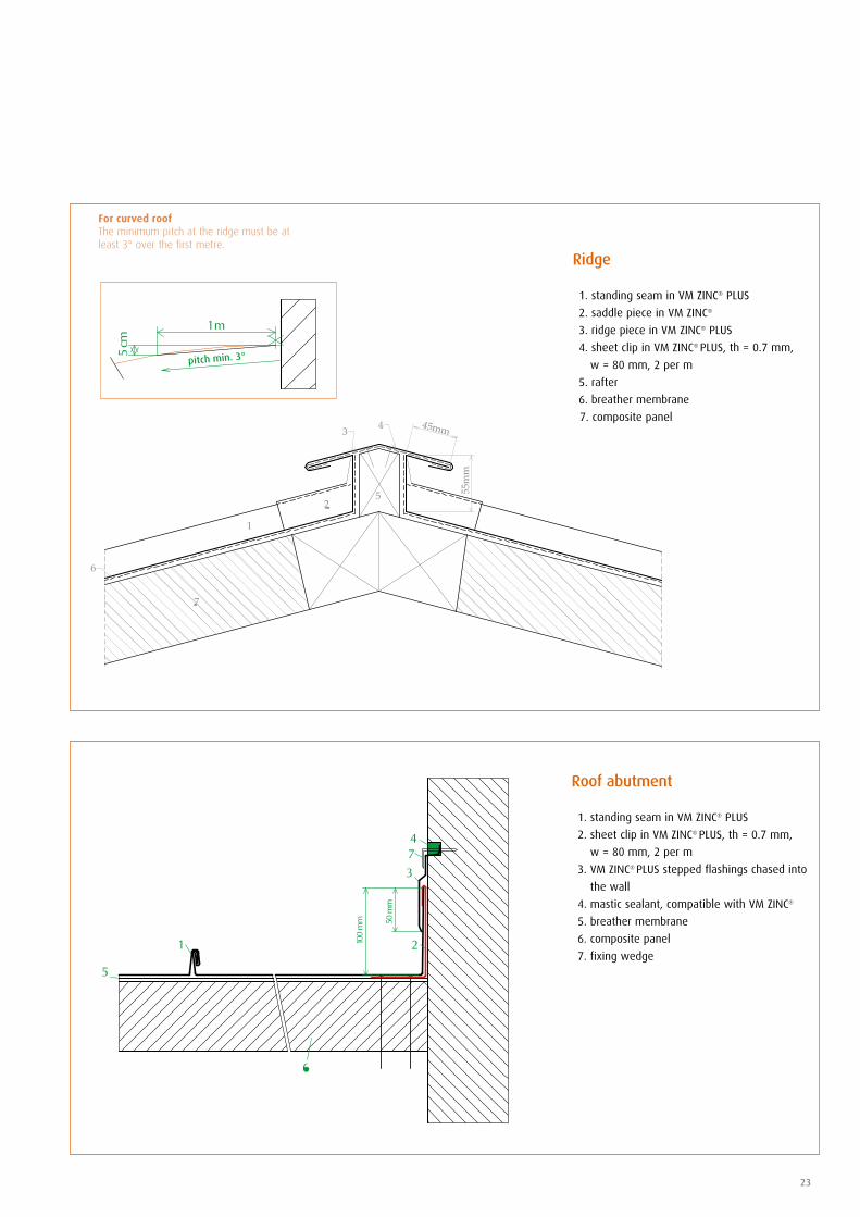
For curved roof The mimimum pitch at the ridge must be at least 3° over first metre
with flat folded clip
with rolled bead
13
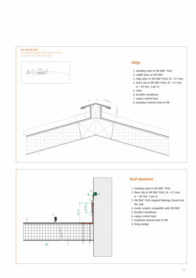
Roof abutment
1. standing seam in VM ZINC® PLUS
2. sheet clip in VM ZINC® PLUS, th = 0.7 mm,
w = 80 mm, 2 per m
3. VM ZINC® PLUS stepped flashings chased into
the wall
4. mastic sealant, compatible with VM ZINC®
5. breather membrane
6. vapour control layer
7. insulation mineral wool or PIR
8. fixing wedge
Ridge
1. standing seam in VM ZINC® PLUS
2. saddle piece in VM ZINC®
3. ridge piece in VM ZINC® PLUS, th = 0.7 mm
4. sheet clip in VM ZINC® PLUS, th = 0.7 mm,
w = 80 mm, 2 per m
5. rafter
6. breather membrane
7. vapour control layer
8. insulation mineral wool or PIR
For curved roof The minimum pitch at the ridge must be at least 3° over the first metre.
pitch min.
Standing Seam - RoofingWarm roof on mineral wool or PIR
14
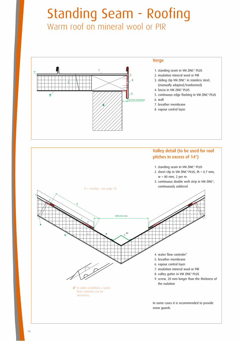
Valley detail (to be used for roofpitches in excess of 14°)
1. standing seam in VM ZINC® PLUS
2. sheet clip in VM ZINC® PLUS, th = 0.7 mm,
w = 80 mm, 2 per m
3. continuous double welt strip in VM ZINC®,
continuously soldered
4. water flow controler*
5. breather membrane
6. vapour control layer
7. insulation mineral wool or PIR
8. valley gutter in VM ZINC® PLUS
9. screw, 20 mm longer than the thickness of
the isulation4* In some conditions a water
flow controler can be necessary.
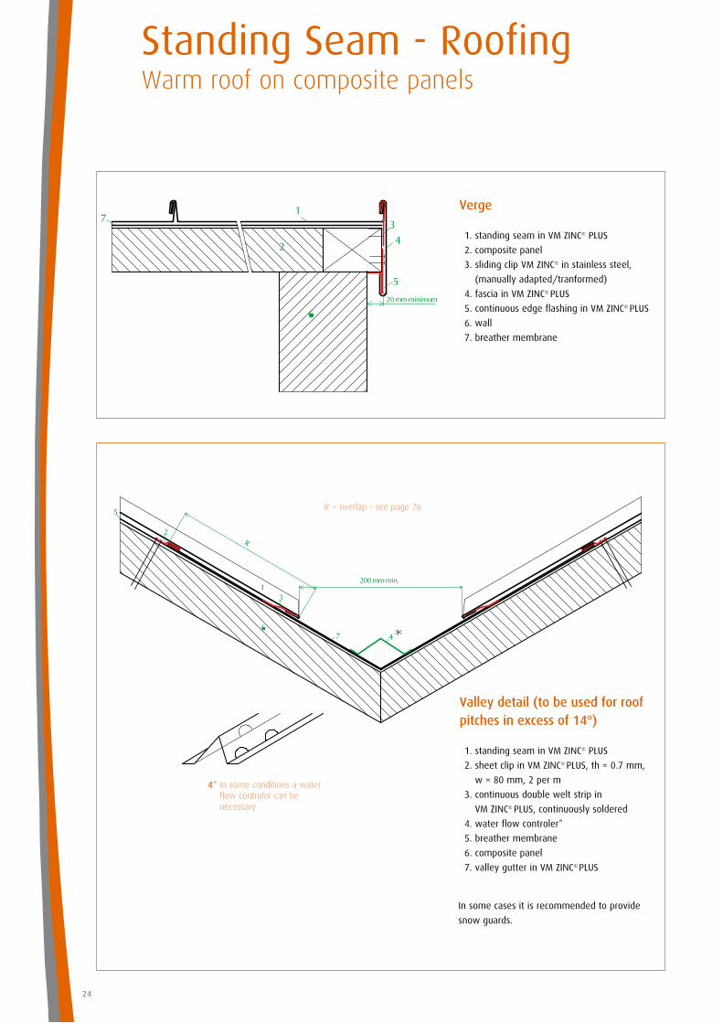
Verge
1. standing seam in VM ZINC® PLUS
2. insulation mineral wool or PIR
3. sliding clip VM ZINC® in stainless steel,
(manually adapted/tranformed)
4. fascia in VM ZINC® PLUS
5. continuous edge flashing in VM ZINC® PLUS
6. wall
7. breather membrane
8. vapour control layer
In some cases it is recommended to provide
snow guards.
R = overlap - see page 76
15
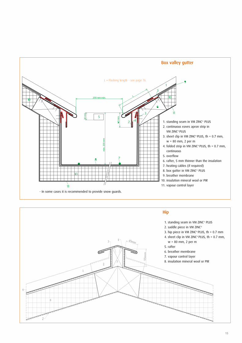
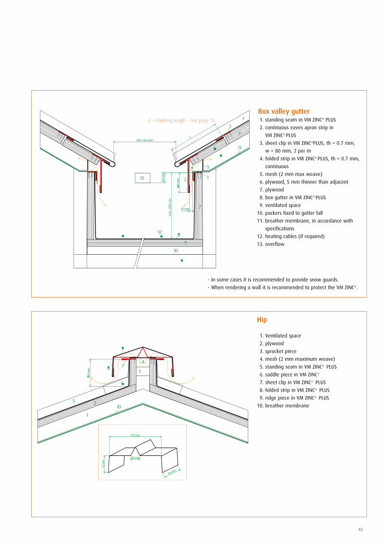
Box valley gutter
1. standing seam in VM ZINC® PLUS
2. continuous eaves apron strip in
VM ZINC® PLUS
3. sheet clip in VM ZINC® PLUS, th = 0.7 mm,
w = 80 mm, 2 per m
4. folded strip in VM ZINC® PLUS, th = 0.7 mm,
continuous
5. overflow
6. rafter, 5 mm thinner than the insulation
7. heating cables (if required)
8. box gutter in VM ZINC® PLUS
9. breather membrane
10. insulation mineral wool or PIR
11. vapour control layer
L = Flashing length - see page 76
Hip
1. standing seam in VM ZINC® PLUS
2. saddle piece in VM ZINC®
3. hip piece in VM ZINC® PLUS, th = 0.7 mm
4. sheet clip in VM ZINC® PLUS, th = 0.7 mm,
w = 80 mm, 2 per m
5. rafter
6. breather membrane
7. vapour control layer
8. insulation mineral wool or PIR
- In some cases it is recommended to provide snow guards.
section AA
section DD
section CC
saddle piece
continuous welting strip
skylight
standing seam in VM ZINC® PLUS
section BB
independent flashing
Standing Seam - RoofingWarm roof on mineral wool or PIR
16
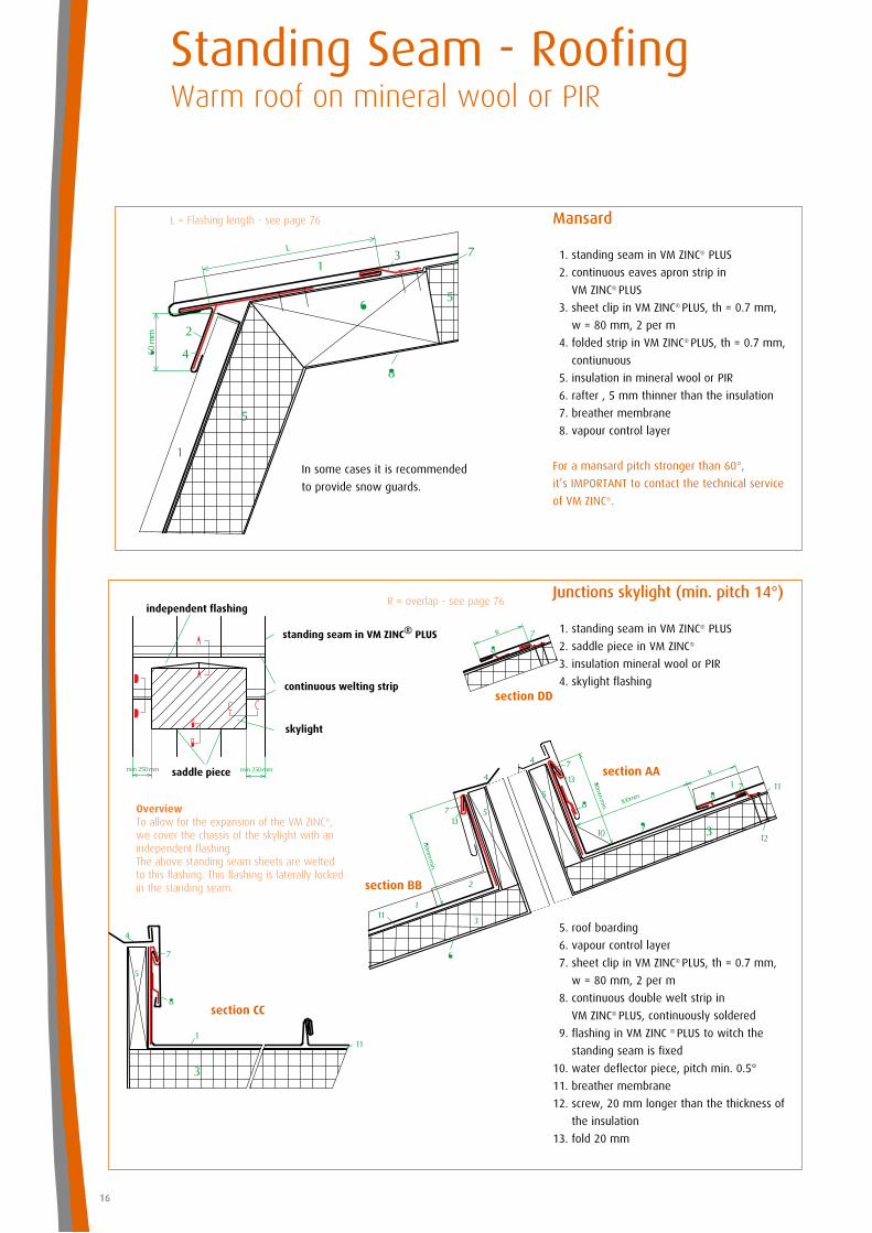
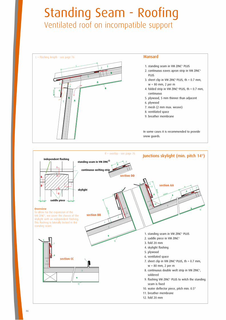
Junctions skylight (min. pitch 14°)
1. standing seam in VM ZINC® PLUS
2. saddle piece in VM ZINC®
3. insulation mineral wool or PIR
4. skylight flashing
5. roof boarding
6. vapour control layer
7. sheet clip in VM ZINC® PLUS, th = 0.7 mm,
w = 80 mm, 2 per m
8. continuous double welt strip in
VM ZINC® PLUS, continuously soldered
9. flashing in VM ZINC ® PLUS to witch the
standing seam is fixed
10. water deflector piece, pitch min. 0.5°
11. breather membrane
12. screw, 20 mm longer than the thickness of
the insulation
13. fold 20 mm
Overview To allow for the expansion of the VM ZINC®, we cover the chassis of the skylight with an independent flashing.The above standing seam sheets are welted to this flashing. This flashing is laterally locked in the standing seam.
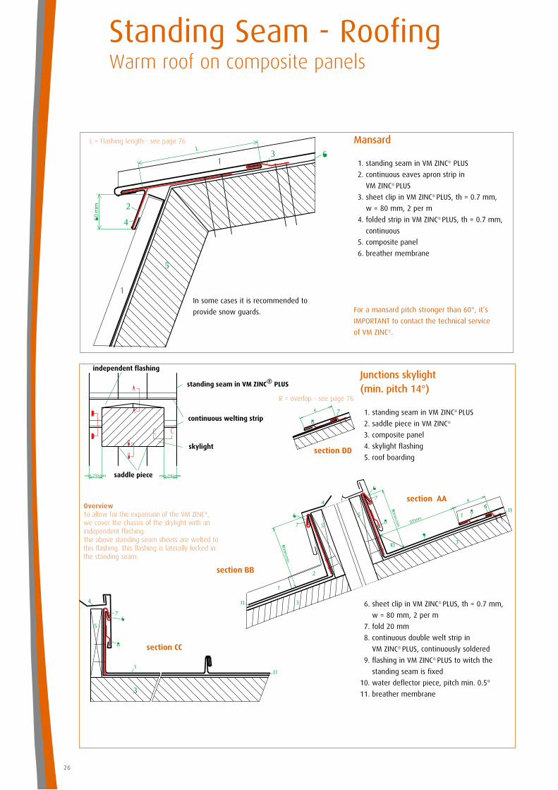
Mansard
1. standing seam in VM ZINC® PLUS
2. continuous eaves apron strip in
VM ZINC® PLUS
3. sheet clip in VM ZINC® PLUS, th = 0.7 mm,
w = 80 mm, 2 per m
4. folded strip in VM ZINC® PLUS, th = 0.7 mm,
contiunuous
5. insulation in mineral wool or PIR
6. rafter , 5 mm thinner than the insulation
7. breather membrane
8. vapour control layer
For a mansard pitch stronger than 60°,
it’s IMPORTANT to contact the technical service
of VM ZINC®.
R = overlap - see page 76
In some cases it is recommended
to provide snow guards.
L = Flashing length - see page 76
section AA
section CC
section BB
standing seam in VM ZINC® PLUS
laid seam, soldered continuously
skylight
saddle piece
17
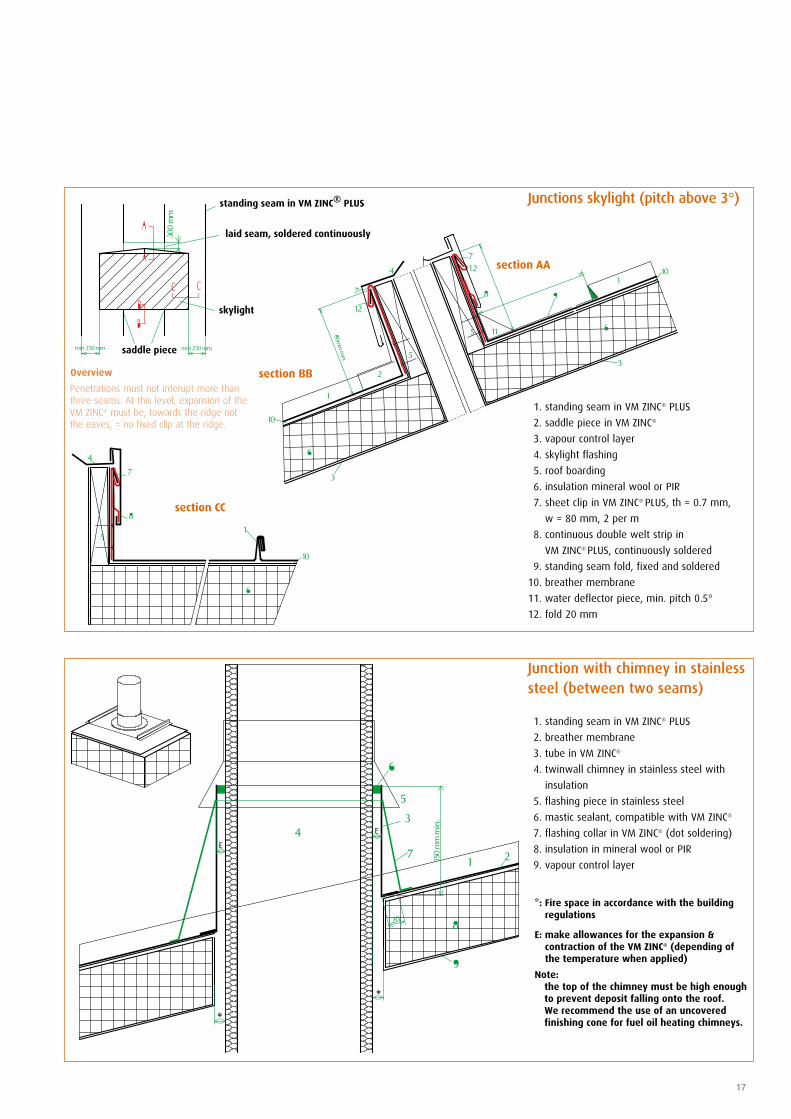
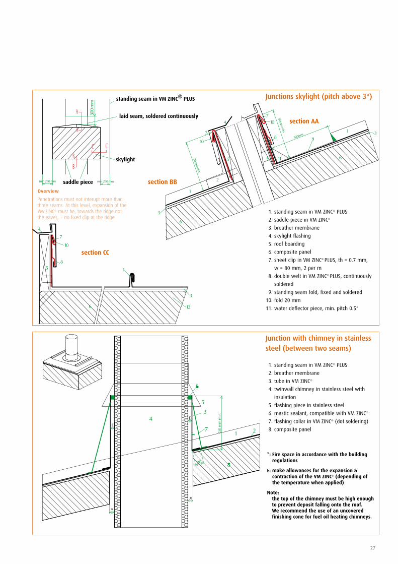
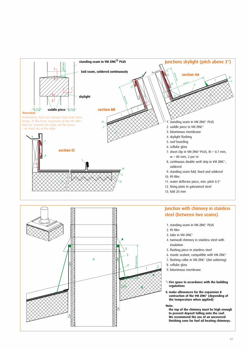
Junction with chimney in stainless steel (between two seams)
1. standing seam in VM ZINC® PLUS
2. breather membrane
3. tube in VM ZINC®
4. twinwall chimney in stainless steel with
insulation
5. flashing piece in stainless steel
6. mastic sealant, compatible with VM ZINC®
7. flashing collar in VM ZINC® (dot soldering)
8. insulation in mineral wool or PIR
9. vapour control layer
Junctions skylight (pitch above 3°)
1. standing seam in VM ZINC® PLUS
2. saddle piece in VM ZINC®
3. vapour control layer
4. skylight flashing
5. roof boarding
6. insulation mineral wool or PIR
7. sheet clip in VM ZINC® PLUS, th = 0.7 mm,
w = 80 mm, 2 per m
8. continuous double welt strip in
VM ZINC® PLUS, continuously soldered
9. standing seam fold, fixed and soldered
10. breather membrane
11. water deflector piece, min. pitch 0.5°
12. fold 20 mm
Penetrations must not interupt more than three seams. At this level, expansion of the VM ZINC® must be, towards the ridge not the eaves, = no fixed clip at the ridge.
Overview
*: Fire space in accordance with the building regulations
E: make allowances for the expansion & contraction of the VM ZINC® (depending of the temperature when applied)
Note: the top of the chimney must be high enough
to prevent deposit falling onto the roof. We recommend the use of an uncovered finishing cone for fuel oil heating chimneys.
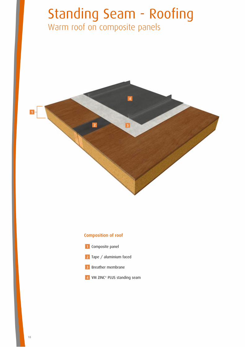
Standing Seam - RoofingWarm roof on composite panels
18
Composition of roof
Composite panel
Tape / aluminium faced
Breather membrane
VM ZINC® PLUS standing seam
1
2
3
4
1
2 3
4
19
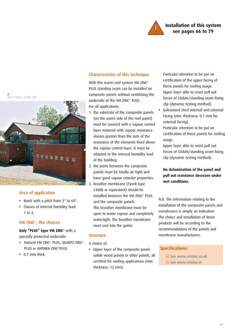
Characteristics of this technique
With this warm roof system VM ZINC®
PLUS standing seam can be installed on
composite panels without ventilating the
underside of the VM ZINC® PLUS.
For all applications:
1. the substrate of the composite panels
(on the warm side of the roof panel)
must be covered with a vapour control
layer material with vapour resistance
always greater than the sum of the
resistance of the elements fixed above
the vapour control layer. It must be
adapted to the internal humidity load
of the building.
2. the joints between the composite
panels must be totally air tight and
have good vapour retarder properties.
3. breather membrane (Tyvek type
2480b or equivalent) should be
installed between the VM ZINC® PLUS
and the composite panels.
This breather membrane must be
open to water vapour and completely
watertight. The breather membrane
must end into the gutter.
Structure
A choice of:
• Upper layer of the composite panel:
solide wood panels or other panels, all
certified for roofing applications (min.
thickness: 12 mm).
Area of application
• Roofs with a pitch from 3° to 60°.
• Classes of internal humidity load:
1 to 4.
VM ZINC®, the choices
Only “PLUS” type VM ZINC® with a
specially protected underside:
• Natural VM ZINC® PLUS, QUARTZ-ZINC®
PLUS or ANTHRA-ZINC®PLUS.
• 0.7 mm thick.
Particular attention to be put on
certification of the upper facing of
these panels for roofing usage.
Upper layer able to resist pull out
forces of 50daN/standing seam fixing
clip (dynamic testing method).
• Galvanised steel internal and external
facing (min. thickness: 0.7 mm for
external facing).
Particular attention to be put on
certification of these panels for roofing
usage.
Upper layer able to resist pull out
forces of 50daN/standing seam fixing
clip (dynamic testing method).
No delamination of the panel and
pull out resistance decrease under
wet conditions.
N.B. The information relating to the
installation of the composite panels and
membranes is simply an indication.
The choice and installation of these
products will be according to the
recommendations of the panels and
membrane manufacturers.
Installation of this system see pages 66 to 79
Arch. P. Poncin - QUARTZ-ZINC®>
Specifications:
: See www.vmzinc.co.uk
: See www.vmzinc.ie
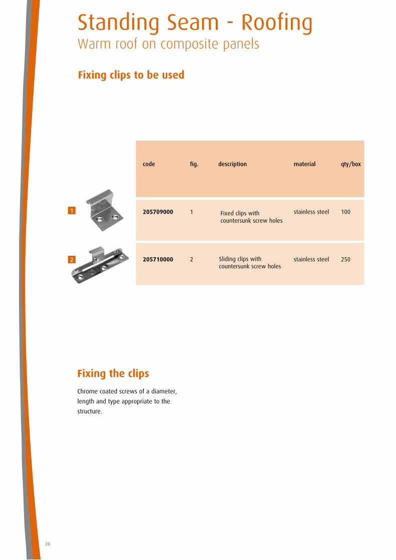
Fixing clips to be used
Standing Seam - RoofingWarm roof on composite panels
20
Sliding clips with countersunk screw holes
Fixed clips with countersunk screw holes
code fig. description material qty/box
205709000 1 stainless steel 100
205710000 2 stainless steel 250
Fixing the clips
Chrome coated screws of a diameter,
length and type appropriate to the
structure.
1
2
pitch min. 1°
pitch min. 1°
21
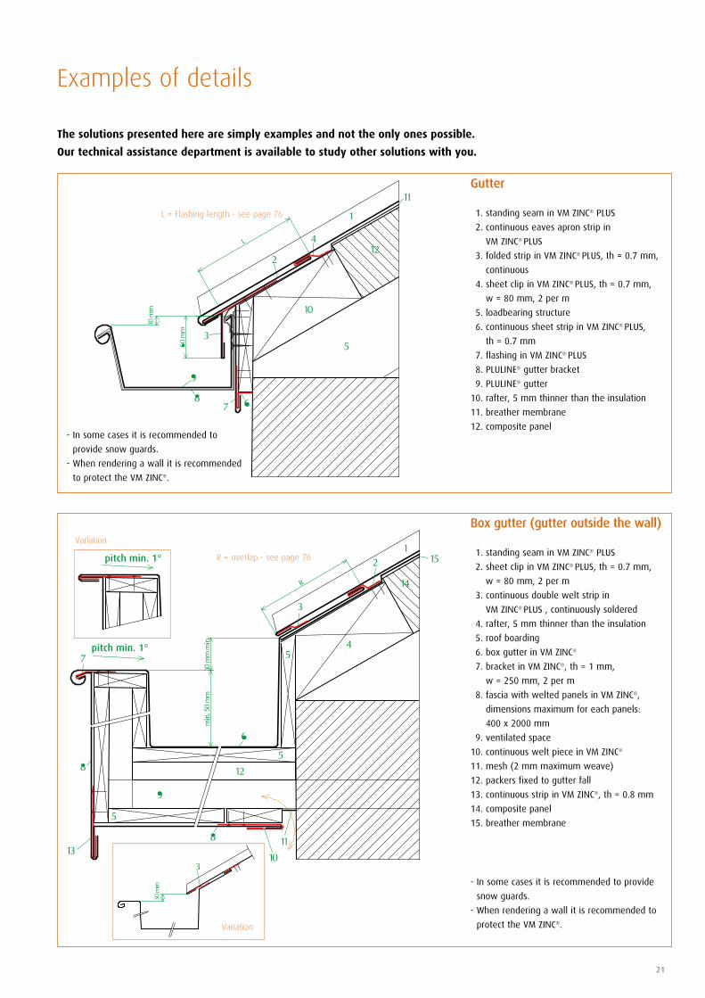
Gutter
1. standing seam in VM ZINC® PLUS
2. continuous eaves apron strip in
VM ZINC® PLUS
3. folded strip in VM ZINC® PLUS, th = 0.7 mm,
continuous
4. sheet clip in VM ZINC® PLUS, th = 0.7 mm,
w = 80 mm, 2 per m
5. loadbearing structure
6. continuous sheet strip in VM ZINC® PLUS,
th = 0.7 mm
7. flashing in VM ZINC® PLUS
8. PLULINE® gutter bracket
9. PLULINE® gutter
10. rafter, 5 mm thinner than the insulation
11. breather membrane
12. composite panel
L = Flashing length - see page 76
Box gutter (gutter outside the wall)
1. standing seam in VM ZINC® PLUS
2. sheet clip in VM ZINC® PLUS, th = 0.7 mm,
w = 80 mm, 2 per m
3. continuous double welt strip in
VM ZINC® PLUS , continuously soldered
4. rafter, 5 mm thinner than the insulation
5. roof boarding
6. box gutter in VM ZINC®
7. bracket in VM ZINC®, th = 1 mm,
w = 250 mm, 2 per m
8. fascia with welted panels in VM ZINC®,
dimensions maximum for each panels:
400 x 2000 mm
9. ventilated space
10. continuous welt piece in VM ZINC®
11. mesh (2 mm maximum weave)
12. packers fixed to gutter fall
13. continuous strip in VM ZINC®, th = 0.8 mm
14. composite panel
15. breather membrane
- In some cases it is recommended to provide
snow guards.
- When rendering a wall it is recommended to
protect the VM ZINC®.
- In some cases it is recommended to
provide snow guards.
- When rendering a wall it is recom mended
to protect the VM ZINC®.
R = overlap - see page 76
Variation
Variation
The solutions presented here are simply examples and not the only ones possible.
Our technical assistance department is available to study other solutions with you.
Examples of details
pitch min. 1°
pitch min. 1°
pitch min. 3°
Standing Seam - RoofingWarm roof on composite panels
22
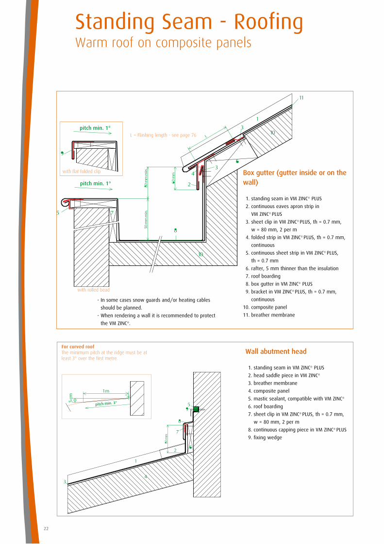
Box gutter (gutter inside or on the wall)
1. standing seam in VM ZINC® PLUS
2. continuous eaves apron strip in
VM ZINC® PLUS
3. sheet clip in VM ZINC® PLUS, th = 0.7 mm,
w = 80 mm, 2 per m
4. folded strip in VM ZINC® PLUS, th = 0.7 mm,
continuous
5. continuous sheet strip in VM ZINC® PLUS,
th = 0.7 mm
6. rafter, 5 mm thinner than the insulation
7. roof boarding
8. box gutter in VM ZINC® PLUS
9. bracket in VM ZINC® PLUS, th = 0.7 mm,
continuous
10. composite panel
11. breather membrane
- In some cases snow guards and/or heating cables
should be planned.
- When rendering a wall it is recommended to protect
the VM ZINC®.
L = Flashing length - see page 76
with flat folded clip
with rolled bead
Wall abutment head
1. standing seam in VM ZINC® PLUS
2. head saddle piece in VM ZINC®
3. breather membrane
4. composite panel
5. mastic sealant, compatible with VM ZINC®
6. roof boarding
7. sheet clip in VM ZINC® PLUS, th = 0.7 mm,
w = 80 mm, 2 per m
8. continuous capping piece in VM ZINC® PLUS
9. fixing wedge
For curved roof The minimum pitch at the ridge must be at least 3° over the first metre.
23
Roof abutment
1. standing seam in VM ZINC® PLUS
2. sheet clip in VM ZINC® PLUS, th = 0.7 mm,
w = 80 mm, 2 per m
3. VM ZINC® PLUS stepped flashings chased into
the wall
4. mastic sealant, compatible with VM ZINC®
5. breather membrane
6. composite panel
7. fixing wedge
Ridge
1. standing seam in VM ZINC® PLUS
2. saddle piece in VM ZINC®
3. ridge piece in VM ZINC® PLUS
4. sheet clip in VM ZINC® PLUS, th = 0.7 mm,
w = 80 mm, 2 per m
5. rafter
6. breather membrane
7. composite panel
For curved roof The minimum pitch at the ridge must be at least 3° over the first metre.
pitch min. 3°
Standing Seam - RoofingWarm roof on composite panels
24
Valley detail (to be used for roofpitches in excess of 14°)
1. standing seam in VM ZINC® PLUS
2. sheet clip in VM ZINC® PLUS, th = 0.7 mm,
w = 80 mm, 2 per m
3. continuous double welt strip in
VM ZINC® PLUS, continuously soldered
4. water flow controler*
5. breather membrane
6. composite panel
7. valley gutter in VM ZINC® PLUS
4* In some conditions a water flow controler can be necessary.
Verge
1. standing seam in VM ZINC® PLUS
2. composite panel
3. sliding clip VM ZINC® in stainless steel,
(manually adapted/tranformed)
4. fascia in VM ZINC® PLUS
5. continuous edge flashing in VM ZINC® PLUS
6. wall
7. breather membrane
In some cases it is recommended to provide
snow guards.
R = overlap - see page 76
25
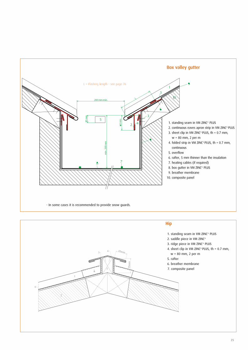
Hip
1. standing seam in VM ZINC® PLUS
2. saddle piece in VM ZINC®
3. ridge piece in VM ZINC® PLUS
4. sheet clip in VM ZINC® PLUS, th = 0.7 mm,
w = 80 mm, 2 per m
5. rafter
6. breather membrane
7. composite panel
Box valley gutter
1. standing seam in VM ZINC® PLUS
2. continuous eaves apron strip in VM ZINC® PLUS
3. sheet clip in VM ZINC® PLUS, th = 0.7 mm,
w = 80 mm, 2 per m
4. folded strip in VM ZINC® PLUS, th = 0.7 mm,
continuous
5. overflow
6. rafter, 5 mm thinner than the insulation
7. heating cables (if required)
8. box gutter in VM ZINC® PLUS
9. breather membrane
10. composite panel
L = Flashing length - see page 76
- In some cases it is recommended to provide snow guards.
section DD
section BB
section AA
saddle piece
continuous welting strip
skylight
standing seam in VM ZINC® PLUS
section CC
independent flashing
6
Standing Seam - RoofingWarm roof on composite panels
26
Junctions skylight (min. pitch 14°)
1. standing seam in VM ZINC® PLUS
2. saddle piece in VM ZINC®
3. composite panel
4. skylight flashing
5. roof boarding
6. sheet clip in VM ZINC® PLUS, th = 0.7 mm,
w = 80 mm, 2 per m
7. fold 20 mm
8. continuous double welt strip in
VM ZINC® PLUS, continuously soldered
9. flashing in VM ZINC® PLUS to witch the
standing seam is fixed
10. water deflector piece, pitch min. 0.5°
11. breather membrane
Overview To allow for the expansion of the VM ZINC®, we cover the chassis of the skylight with an independent flashing.The above standing seam sheets are welted to this flashing. This flashing is laterally locked in the standing seam.
Mansard
1. standing seam in VM ZINC® PLUS
2. continuous eaves apron strip in
VM ZINC® PLUS
3. sheet clip in VM ZINC® PLUS, th = 0.7 mm,
w = 80 mm, 2 per m
4. folded strip in VM ZINC® PLUS, th = 0.7 mm,
continuous
5. composite panel
6. breather membrane
For a mansard pitch stronger than 60°, it’s
IMPORTANT to contact the technical service
of VM ZINC®.
R = overlap - see page 76
In some cases it is recommended to
provide snow guards.
L = Flashing length - see page 76
section AA
section CC
standing seam in VM ZINC® PLUS
laid seam, soldered continuously
skylight
saddle piece section BB
27
Junction with chimney in stainless steel (between two seams)
1. standing seam in VM ZINC® PLUS
2. breather membrane
3. tube in VM ZINC®
4. twinwall chimney in stainless steel with
insulation
5. flashing piece in stainless steel
6. mastic sealant, compatible with VM ZINC®
7. flashing collar in VM ZINC® (dot soldering)
8. composite panel
Junctions skylight (pitch above 3°)
1. standing seam in VM ZINC® PLUS
2. saddle piece in VM ZINC®
3. breather membrane
4. skylight flashing
5. roof boarding
6. composite panel
7. sheet clip in VM ZINC® PLUS, th = 0.7 mm,
w = 80 mm, 2 per m
8. double welt in VM ZINC® PLUS, continuously
soldered
9. standing seam fold, fixed and soldered
10. fold 20 mm
11. water deflector piece, min. pitch 0.5°
*: Fire space in accordance with the building regulations
E: make allowances for the expansion & contraction of the VM ZINC® (depending of the temperature when applied)
Note: the top of the chimney must be high enough
to prevent deposit falling onto the roof. We recommend the use of an uncovered finishing cone for fuel oil heating chimneys.
Penetrations must not interupt more than three seams. At this level, expansion of the VM ZINC® must be, towards the ridge not the eaves, = no fixed clip at the ridge.
Overview
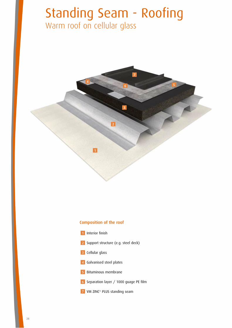
Standing Seam - RoofingWarm roof on cellular glass
28
Composition of the roof
Interior finish
Support structure (e.g. steel deck)
Cellular glass
Galvanised steel plates
Bituminous membrane
Separation layer / 1000 guage PE film
VM ZINC® PLUS standing seam
1
1
2
2
3
3
4
4
5
6
7
56
7
29
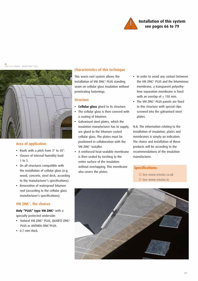
Characteristics of this technique
This warm roof system allows the
installation of VM ZINC® PLUS standing
seam on cellular glass insulation without
penetrating fastenings.
Structure
• Cellular glass glued to its structure.
• The cellular glass is then covered with
a coating of bitumen.
• Galvanised steel plates, which the
insulation manufacturer has to supply,
are glued to the bitumen coated
cellular glass. The plates must be
positioned in collaboration with the
VM ZINC® installer.
• A reinforced heat-sealable membrane
is then sealed by torching to the
entire surface of the insulation
without overlapping. This membrane
also covers the plates.
Area of application
• Roofs with a pitch from 3° to 45°.
• Classes of internal humidity load:
1 to 5.
• On all structures compatible with
the installation of cellular glass (e.g.
wood, concrete, steel deck, according
to the manufacturer’s specifications).
• Renovation of waterproof bitumen
roof (according to the cellular glass
manufacturer’s specifications).
VM ZINC®, the choices
Only “PLUS” type VM ZINC® with a
specially protected underside:
• Natural VM ZINC® PLUS, QUARTZ-ZINC®
PLUS or ANTHRA-ZINC®PLUS.
• 0.7 mm thick.
• In order to avoid any contact between
the VM ZINC® PLUS and the bituminous
membrane, a transparent polyethy-
lene separation membrane is fixed
with an overlap of + 150 mm.
• The VM ZINC® PLUS panels are fixed
to this structure with special clips
screwed into the galvanised steel
plates.
N.B. The information relating to the
installation of insulation, plates and
membranes is simply an indication.
The choice and installation of these
products will be according to the
recommendations of the insulation
manufacturer.
Arch. S & C Molina - QUARTZ-ZINC® PLUS>
Installation of this system see pages 66 to 79
Specifications:
: See www.vmzinc.co.uk
: See www.vmzinc.ie
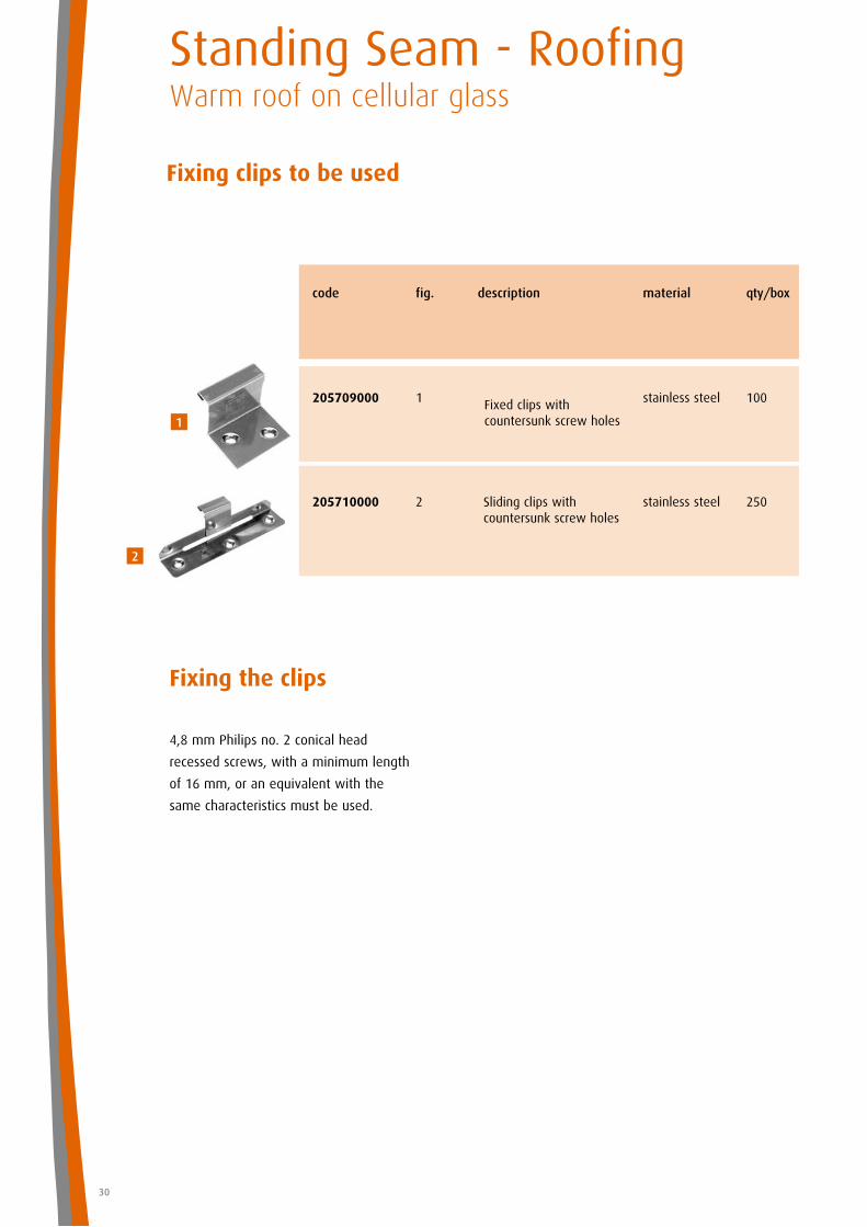
Fixing clips to be used
Fixing the clips
4,8 mm Philips no. 2 conical head
recessed screws, with a minimum length
of 16 mm, or an equivalent with the
same characteristics must be used.
Standing Seam - RoofingWarm roof on cellular glass
30
Sliding clips with countersunk screw holes
Fixed clips with countersunk screw holes
code fig. description material qty/box
205709000 1 stainless steel 100
205710000 2 stainless steel 250
1
2

pitch min. 1°
pitch min. 1°
31
Gutter
1. standing seam in VM ZINC® PLUS
2. continuous eaves apron strip in VM ZINC®PLUS
3. continuous folded strip in VM ZINC® PLUS,
th=0.7 mm
4. sheet clip in VM ZINC® PLUS, th = 0.7 mm,
w = 80 mm, 2 per m
5. loadbearing structure
6. continuous sheet strip in VM ZINC® PLUS,
th = 0.7 mm
7. flashing in VM ZINC® PLUS
8. PLULINE® gutter bracket
9. PLULINE® gutter
10. rafter, 5 mm thinner than the insulation
11. PE-film
12. bituminous membrane
13. cellular glass
L = Flashing length - see page 76
Box gutter (gutter outside the wall)
1. standing seam in VM ZINC® PLUS
2. sheet clip in VM ZINC® PLUS, th = 0.7 mm,
w = 80 mm, 2 per m
3. continuous double welt strip in
VM ZINC®, soldered
4. rafter, 5 mm thinner than the insulation
5. roof boarding
6. box gutter in VM ZINC®
7. bracket in VM ZINC®, th = 1 mm,
w = 250 mm, 2 per m
8. fascia with welted panels in VM ZINC®,
dimensions maximum for each panel:
400 x 2000 mm
9. ventilated space
10. continuous welt piece in VM ZINC®
11. mesh (2 mm maximum weave)
12. packers fixed to gutter fall
13. continuous strip in VM ZINC®, th = 0.8 mm
14. cellular glass
15. bituminous membrane
16. PE-film
- In some cases it is recommended to provide
snow guards.
- When rendering a wall it is recommended to
protect the VM ZINC®.
- In some cases it is recommended to
provide snow guards.
- When rendering a wall it is recom mended
to protect the VM ZINC®.
R = overlap - see page 76
Variation
Variation
The solutions presented here are simply examples and not the only ones possible.
Our technical assistance department is available to study other solutions with you.
Examples of details
pitch min. 3°
pitch min. 1°
pitch min. 1°
Standing Seam - RoofingWarm roof on cellular glass
32
Box gutter (gutter inside or on the wall)
1. standing seam in VM ZINC® PLUS
2. continuous eaves apron strip in
VM ZINC® PLUS
3. sheet clip in VM ZINC® PLUS, th = 0.7 mm,
w = 80 mm, 2 per m
4. folded strip in VM ZINC® PLUS, th = 0.7 mm,
continuous
5. continuous sheet strip in VM ZINC® PLUS,
th = 0.7 mm
6. rafter, 5 mm thinner than the insulation
7. roof boarding
8. box gutter in VM ZINC® PLUS
9. bracket in VM ZINC® PLUS, th = 0.7 mm,
continuous
10. bituminous membrane
11. PE-film
12. cellular glass
- In some cases snow guards and/or heating cables
should be planned.
- When rendering a wall it is recommended to protect
the VM ZINC®.
L = Flashing length - see page 76
with flat folded clip
with rolled bead
Wall abutment head
1. standing seam in VM ZINC® PLUS
2. head saddle piece in VM ZINC®
3. PE-film
4. bituminous membrane
5. cellular glass
6. roof boarding
7. sheet clip in VM ZINC® PLUS, th = 0.7 mm,
w = 80 mm, 2 per m
8. continuous capping piece in VM ZINC® PLUS
9. fixing wedge
10. mastic sealant, compatible with VM ZINC®
For curved roof The minimum pitch at the ridge must be at least 3° over the first metre.
- When rendering a wall it is recommended to protect the VM ZINC®.
33
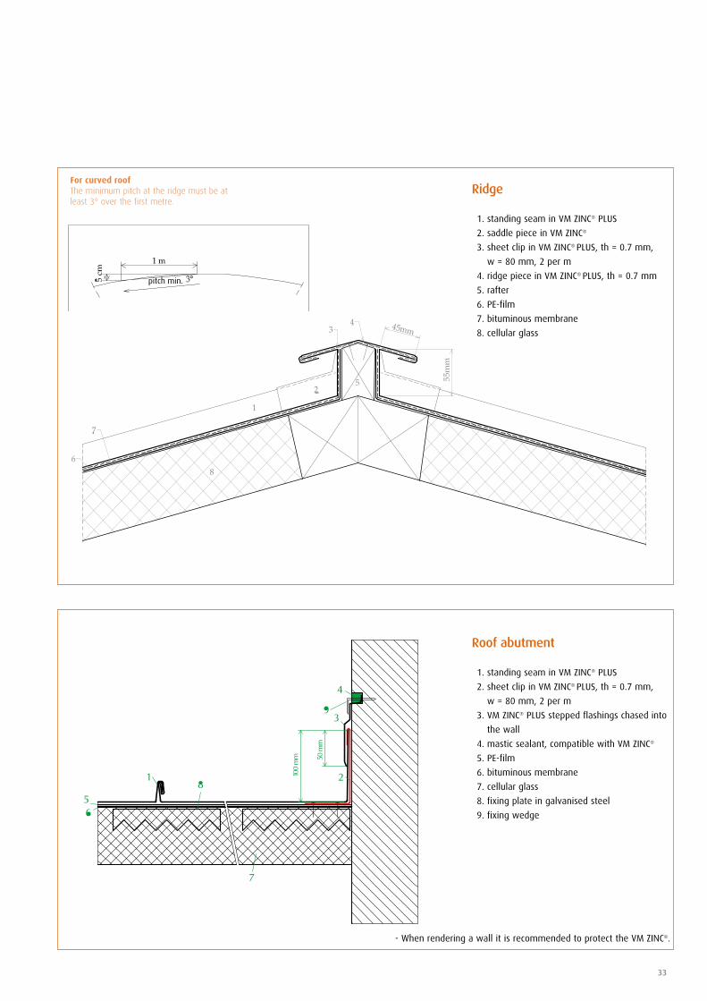
Roof abutment
1. standing seam in VM ZINC® PLUS
2. sheet clip in VM ZINC® PLUS, th = 0.7 mm,
w = 80 mm, 2 per m
3. VM ZINC® PLUS stepped flashings chased into
the wall
4. mastic sealant, compatible with VM ZINC®
5. PE-film
6. bituminous membrane
7. cellular glass
8. fixing plate in galvanised steel
9. fixing wedge
Ridge
1. standing seam in VM ZINC® PLUS
2. saddle piece in VM ZINC®
3. sheet clip in VM ZINC® PLUS, th = 0.7 mm,
w = 80 mm, 2 per m
4. ridge piece in VM ZINC® PLUS, th = 0.7 mm
5. rafter
6. PE-film
7. bituminous membrane
8. cellular glass
For curved roof The minimum pitch at the ridge must be at least 3° over the first metre.
- When rendering a wall it is recommended to protect the VM ZINC®.
pitch min.
Standing Seam - RoofingWarm roof on cellular glass
34
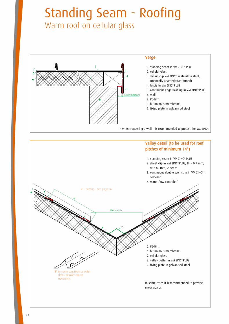
Valley detail (to be used for roofpitches of minimum 14°)
1. standing seam in VM ZINC® PLUS
2. sheet clip in VM ZINC® PLUS, th = 0.7 mm,
w = 80 mm, 2 per m
3. continuous double welt strip in VM ZINC® ,
soldered
4. water flow controler*
5. PE-film
6. bituminous membrane
7. cellular glass
8. valley gutter in VM ZINC® PLUS
9. fixing plate in galvanised steel
4* In some conditions a water flow controler can be necessary.
Verge
1. standing seam in VM ZINC® PLUS
2. cellular glass
3. sliding clip VM ZINC® in stainless steel,
(manually adapted/tranformed)
4. fascia in VM ZINC® PLUS
5. continuous edge flashing in VM ZINC® PLUS
6. wall
7. PE-film
8. bituminous membrane
9. fixing plate in galvanised steel
In some cases it is recommended to provide
snow guards.
R = overlap - see page 76
- When rendering a wall it is recommended to protect the VM ZINC®.
35
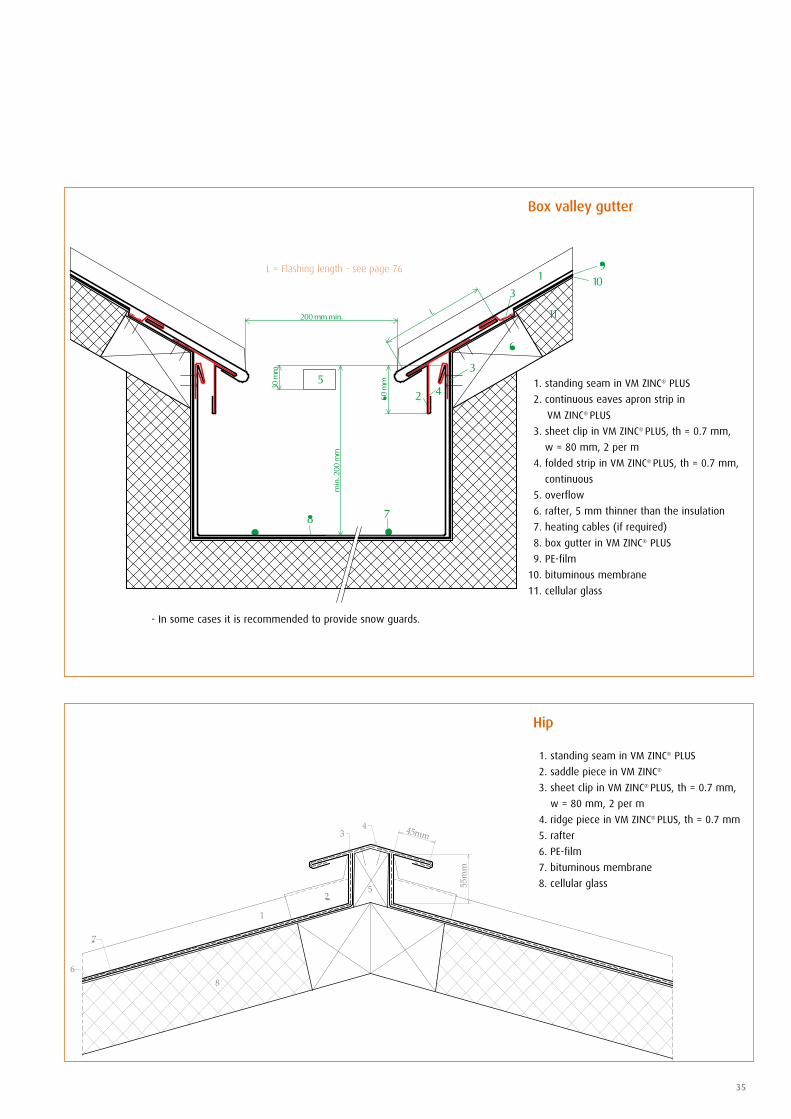
Hip
1. standing seam in VM ZINC® PLUS
2. saddle piece in VM ZINC®
3. sheet clip in VM ZINC® PLUS, th = 0.7 mm,
w = 80 mm, 2 per m
4. ridge piece in VM ZINC® PLUS, th = 0.7 mm
5. rafter
6. PE-film
7. bituminous membrane
8. cellular glass
Box valley gutter
1. standing seam in VM ZINC® PLUS
2. continuous eaves apron strip in
VM ZINC® PLUS
3. sheet clip in VM ZINC® PLUS, th = 0.7 mm,
w = 80 mm, 2 per m
4. folded strip in VM ZINC® PLUS, th = 0.7 mm,
continuous
5. overflow
6. rafter, 5 mm thinner than the insulation
7. heating cables (if required)
8. box gutter in VM ZINC® PLUS
9. PE-film
10. bituminous membrane
11. cellular glass
L = Flashing length - see page 76
- In some cases it is recommended to provide snow guards.

section DD
section BB
section AA
saddle piece
continuous welting strip
skylight
standing seam in VM ZINC® PLUS
section CC
independent flashing
Standing Seam - RoofingWarm roof on cellular glass
36
Junctions skylight (min. pitch 14°)
1. standing seam in VM ZINC® PLUS
2. saddle piece in VM ZINC®
3. cellular glass
4. skylight flashing
5. roof boarding
6. bituminous membrane
7. sheet clip in VM ZINC® PLUS, th = 0.7 mm,
w = 80 mm, 2 per m
8. continuous double welt strip in VM ZINC®
PLUS, continuously soldered
9. flashing to witch the standing seam is fixed
10. water deflector piece, pitch min. 0.5°
11. PE-film
12. fixing plate in galvanised steel
13. fold 20 mm
Overview To allow for the expansion of the VM ZINC®, we cover the chassis of the skylight with an independent flashing.The above standing seam sheets are welted to this flashing. This flashing is laterally locked in the standing seam.
Mansard
1. standing seam in VM ZINC® PLUS
2. continuous eaves apron strip in VM ZINC®
PLUS
3. sheet clip in VM ZINC® PLUS, th = 0.7 mm,
w = 80 mm, 2 per m
4. folded clip in VM ZINC® PLUS, th = 0.7 mm,
continuous
5. cellular glass
6. fixing plate in galvanised steel
7. PE-film
8. bituminous membrane
For a mansard pitch stronger than 45°, it’s
IMPORTANT to contact the technical service
of VM ZINC®.
R = overlap - see page 76
In some cases it is recommended to
provide snow guards.
L = Flashing length - see page 76
section AA
section CC
standing seam in VM ZINC® PLUS
laid seam, soldered continuously
skylight
saddle piece section BB
37
Junction with chimney in stainless steel (between two seams)
1. standing seam in VM ZINC® PLUS
2. PE-film
3. tube in VM ZINC®
4. twinwall chimney in stainless steel with
insulation
5. flashing piece in stainless steel
6. mastic sealant, compatible with VM ZINC®
7. flashing collar in VM ZINC® (dot soldering)
8. cellular glass
9. bituminous membrane
Junctions skylight (pitch above 3°)
1. standing seam in VM ZINC® PLUS
2. saddle piece in VM ZINC®
3. bituminous membrane
4. skylight flashing
5. roof boarding
6. cellular glass
7. sheet clip in VM ZINC® PLUS, th = 0.7 mm,
w = 80 mm, 2 per m
8. continuous double welt strip in VM ZINC® ,
soldered
9. standing seam fold, fixed and soldered
10. PE-film
11. water deflector piece, min. pitch 0.5°
12. fixing plate in galvanised steel
13. fold 20 mm
Penetrations must not interupt more than three seams. At this level, expansion of the VM ZINC® must be, towards the ridge not the eaves, = no fixed clip at the ridge.
Overview
*: Fire space in accordance with the building regulations
E: make allowances for the expansion & contraction of the VM ZINC® (depending of the temperature when applied)
Note: the top of the chimney must be high enough
to prevent deposit falling onto the roof. We recommend the use of an uncovered finishing cone for fuel oil heating chimneys.
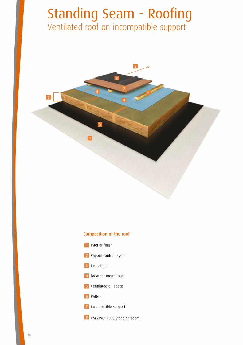
Standing Seam - Roofing Ventilated roof on incompatible support
38
Composition of the roof
Interior finish
Vapour control layer
Insulation
Breather membrane
Ventilated air space
Rafter
Incompatible support
VM ZINC® PLUS Standing seam
1
2
3
4
5
6
7
8
1
2
4
67
8
5
5
3
39
Installation of this system see pages 66 to 79
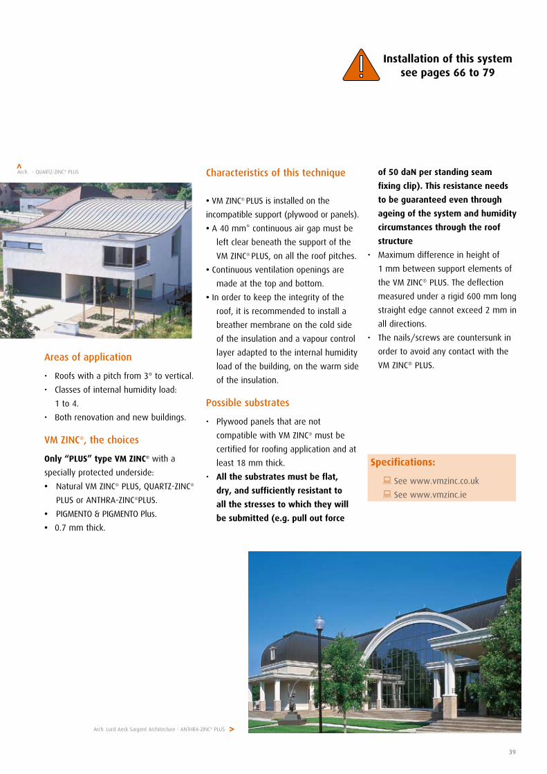
Areas of application
• Roofs with a pitch from 3° to vertical.
• Classes of internal humidity load:
1 to 4.
• Both renovation and new buildings.
VM ZINC®, the choices
Only “PLUS” type VM ZINC® with a
specially protected underside:
• Natural VM ZINC® PLUS, QUARTZ-ZINC®
PLUS or ANTHRA-ZINC®PLUS.
• PIGMENTO & PIGMENTO Plus.
• 0.7 mm thick.
of 50 daN per standing seam
fixing clip). This resistance needs
to be guaranteed even through
ageing of the system and humidity
circumstances through the roof
structure
• Maximumdifferenceinheightof
1 mm between support elements of
the VM ZINC® PLUS. The deflection
measured under a rigid 600 mm long
straight edge cannot exceed 2 mm in
all directions.
• Thenails/screwsarecountersunkin
order to avoid any contact with the
VM ZINC® PLUS.
Arch. - QUARTZ-ZINC® PLUS>
Arch. Lord Aeck Sargent Architecture - ANTHRA-ZINC® PLUS>
Specifications:
: See www.vmzinc.co.uk
: See www.vmzinc.ie
Characteristics of this technique
• VM ZINC® PLUS is installed on the
incompatible support (plywood or panels).
• A 40 mm* continuous air gap must be
left clear beneath the support of the
VM ZINC® PLUS, on all the roof pitches.
• Continuous ventilation openings are
made at the top and bottom.
• In order to keep the integrity of the
roof, it is recommended to install a
breather membrane on the cold side
of the insulation and a vapour control
layer adapted to the internal humidity
load of the building, on the warm side
of the insulation.
Possible substrates
• Plywoodpanelsthatarenot
compatible with VM ZINC® must be
certified for roofing application and at
least 18 mm thick.
• All the substrates must be flat,
dry, and sufficiently resistant to
all the stresses to which they will
be submitted (e.g. pull out force
Standing Seam - Roofing Ventilated roof on incompatible support
40
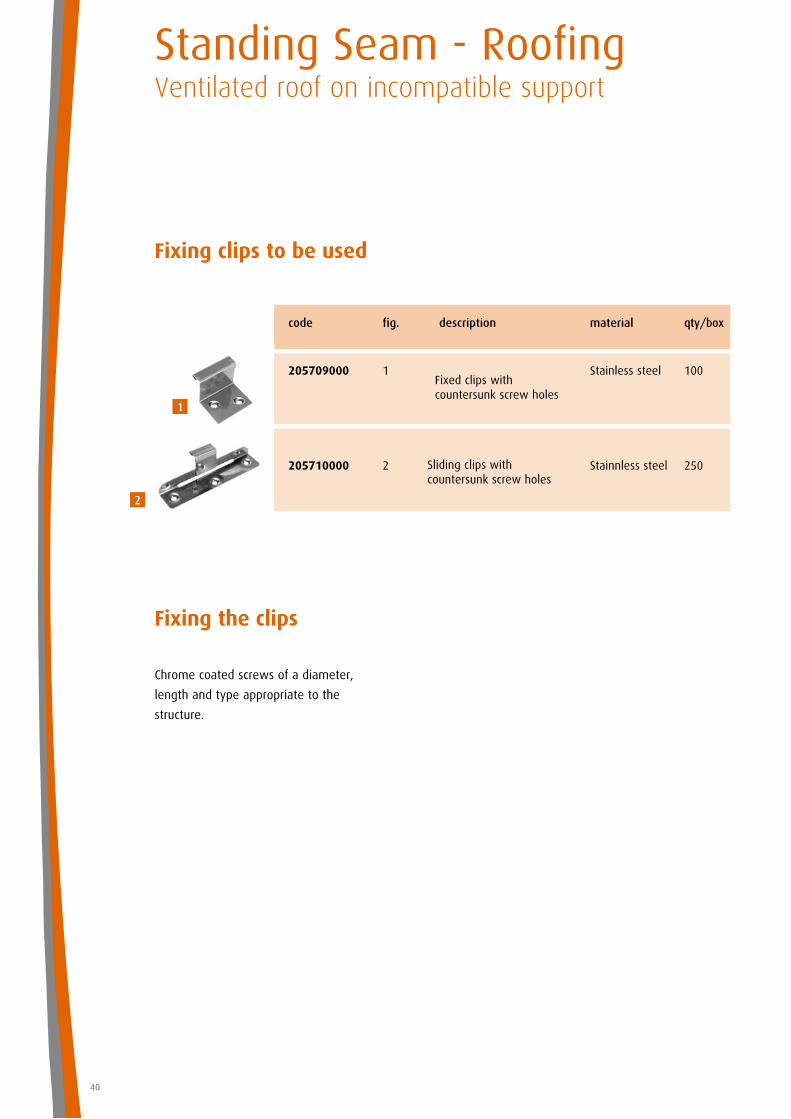
Fixing clips to be used
Fixing the clips
Chrome coated screws of a diameter,
length and type appropriate to the
structure.
Sliding clips with countersunk screw holes
Fixed clips with countersunk screw holes
code fig. description material qty/box
205709000 1 Stainless steel 100
205710000 2 Stainnless steel 250
1
2
41
The solutions presented here are simply examples and are not the only possibilities.
Our technical assistance department is available to study other alternatives with you.
Examples of details
The solutions presented here are simply examples and are not the only possibilities.
Our technical assistance department is available to study other alternatives with you.
Gutter
1. standing seam in VM ZINC® PLUS
2. Sheet clip in vm zinc® plus
th= 0.7 mm , l=80 mm, 2 per m
3 continuous eaves apron strip in VM ZINC ®
PLUS
4. plywood, 5 mm thinner than adjacent
5. plywood
6. ventilated space
7. folded strip in VM ZINC® PLUS, th = 0.7 mm,
continuous
8. flashing in VM ZINC® PLUS
9. continuous sheet strip in VM ZINC®plus,
th = 0.7 mm
10. PLULINE® gutter bracket
11. PLULINE® gutter
12. breather membrane
13. mesh (2 mm max. weave)
L = Flashing length - see page 76
Box gutter (gutter outside the wall) 1. standing seam in VM ZINC®
2. sheet clip in VM ZINC®, th = 0.7 mm,
w = 80 mm, 2 per m
3. continuous welting strip in VM ZINC®, soldered
4. plywood, 5 mm thinner than adjacent
5. plywood
6. boxed gutter in VM ZINC® PLUS
7. bracket in VM ZINC® PLUS, th = 0.7 mm,
continuous
8. fascia with welted panels in VM ZINC® PLUS,
dimensions maximum for each panel:
400 x 2000 mm
9. breather membrane
10. continuous welt piece in VM ZINC®
11. mesh (2 mm maximum weave)
12. packers laid to gutter fall
13. continuous strip in VM ZINC® PLUS,
th = 0.7 mm
14. ventilated space
- In some cases it is recommended to provide
snow guards.
- When rendering a wall it is recommended to
protect the VM ZINC®.
pitch 1°
14
pitch 1°
R=overlap page 76
- In some cases it is recommended to provide
snow guards.
- When rendering a wall it is recommended to
protect the VM ZINC®.
- In some cases it is recommended to provide
snow guards.
- When cementing a wall it is recommended to
protect the VM ZINC®.
Standing Seam - RoofingVentilated roof on incompatible support
42
pitch min. 3°
pitch 1°
pitch 1°
9
12
for curved roof
L = page 76
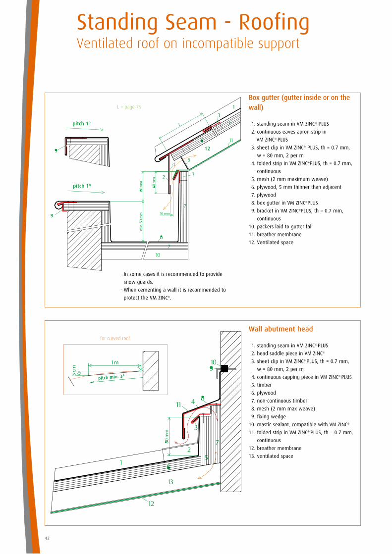
Box gutter (gutter inside or on the wall)
1. standing seam in VM ZINC® PLUS
2. continuous eaves apron strip in
VM ZINC® PLUS
3. sheet clip in VM ZINC® PLUS, th = 0.7 mm,
w = 80 mm, 2 per m
4. folded strip in VM ZINC®PLUS, th = 0.7 mm,
continuous
5. mesh (2 mm maximum weave)
6. plywood, 5 mm thinner than adjacent
7. plywood
8. box gutter in VM ZINC®PLUS
9. bracket in VM ZINC®PLUS, th = 0.7 mm,
continuous
10. packers laid to gutter fall
11. breather membrane
12. Ventilated space
Wall abutment head
1. standing seam in VM ZINC® PLUS
2. head saddle piece in VM ZINC®
3. sheet clip in VM ZINC® PLUS, th = 0.7 mm,
w = 80 mm, 2 per m
4. continuous capping piece in VM ZINC® PLUS
5. timber
6. plywood
7. non-continuous timber
8. mesh (2 mm max weave)
9. fixing wedge
10. mastic sealant, compatible with VM ZINC®
11. folded strip in VM ZINC® PLUS, th = 0.7 mm,
continuous
12. breather membrane
13. ventilated space
43
pitch min. 3°
for curved roof
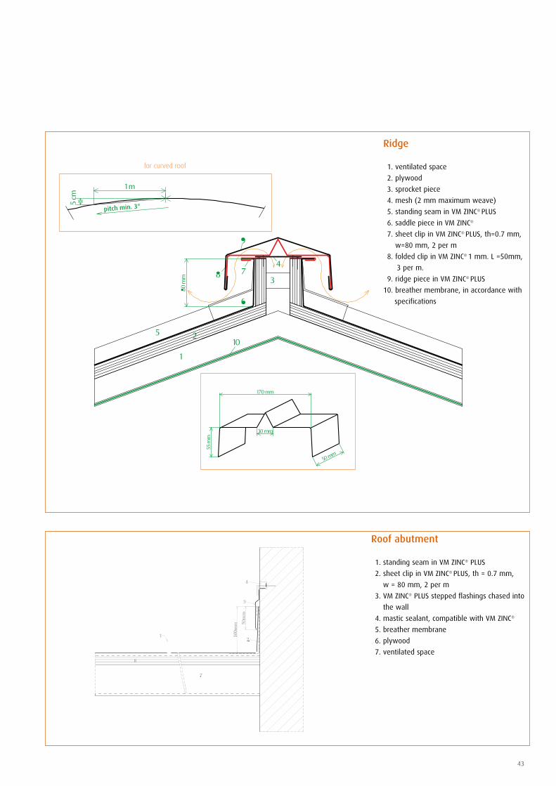
Ridge
1. ventilated space
2. plywood
3. sprocket piece
4. mesh (2 mm maximum weave)
5. standing seam in VM ZINC® PLUS
6. saddle piece in VM ZINC®
7. sheet clip in VM ZINC® PLUS, th=0.7 mm,
w=80 mm, 2 per m
8. folded clip in VM ZINC® 1 mm. L =50mm,
3 per m.
9. ridge piece in VM ZINC® PLUS
10. breather membrane, in accordance with
specifications
Roof abutment
1. standing seam in VM ZINC® PLUS
2. sheet clip in VM ZINC® PLUS, th = 0.7 mm,
w = 80 mm, 2 per m
3. VM ZINC® PLUS stepped flashings chased into
the wall
4. mastic sealant, compatible with VM ZINC®
5. breather membrane
6. plywood
7. ventilated space
Standing Seam - RoofingVentilated roof on incompatible support
44
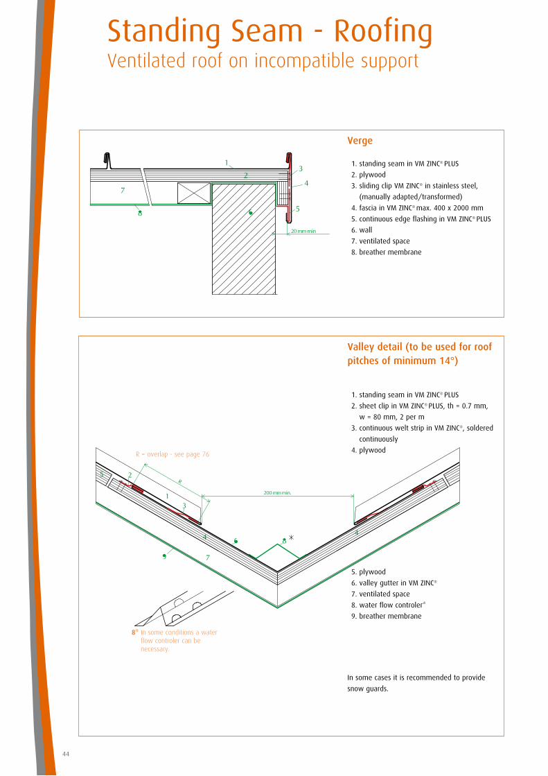
8* In some conditions a water flow controler can be necessary.
In some cases it is recommended to provide
snow guards.
R = overlap - see page 76
Valley detail (to be used for roofpitches of minimum 14°)
1. standing seam in VM ZINC® PLUS
2. sheet clip in VM ZINC® PLUS, th = 0.7 mm,
w = 80 mm, 2 per m
3. continuous welt strip in VM ZINC®, soldered
continuously
4. plywood
5. plywood
6. valley gutter in VM ZINC®
7. ventilated space
8. water flow controler*
9. breather membrane
Verge
1. standing seam in VM ZINC® PLUS
2. plywood
3. sliding clip VM ZINC® in stainless steel,
(manually adapted/transformed)
4. fascia in VM ZINC® max. 400 x 2000 mm
5. continuous edge flashing in VM ZINC® PLUS
6. wall
7. ventilated space
8. breather membrane
45
- In some cases it is recommended to provide snow guards.
- When rendering a wall it is recom mended to protect the VM ZINC®.
Hip
1. Ventilated space
2. plywood
3. sprocket piece
4. mesh (2 mm maximum weave)
5. standing seam in VM ZINC® PLUS
6. saddle piece in VM ZINC®
7. sheet clip in VM ZINC® PLUS
8. folded strip in VM ZINC® PLUS
9. ridge piece in VM ZINC® PLUS
10. breather membrane
Box valley gutter 1. standing seam in VM ZINC® PLUS
2. continuous eaves apron strip in
VM ZINC® PLUS
3. sheet clip in VM ZINC®PLUS, th = 0.7 mm,
w = 80 mm, 2 per m
4. folded strip in VM ZINC® PLUS, th = 0.7 mm,
continuous
5. mesh (2 mm max weave)
6. plywood, 5 mm thinner than adjacent
7. plywood
8. box gutter in VM ZINC® PLUS
9. ventilated space
10. packers fixed to gutter fall
11. breather membrane, in accordance with
specifications
12. heating cables (if required)
13. overflow
L = Flashing length - see page 76
section CC
section AA
section DD
section BB
saddle piece
continuous welting strip
skylight
standing seam in VM ZINC®independent flashing
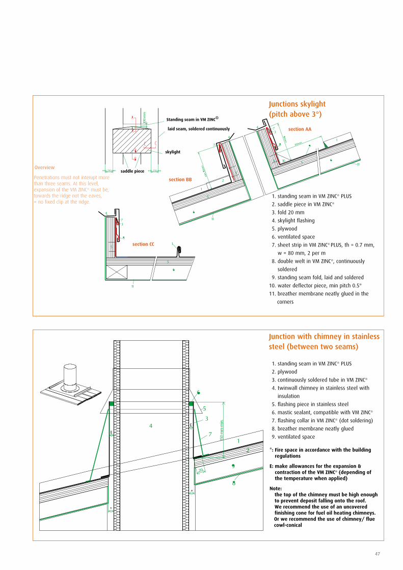
Junctions skylight (min. pitch 14°)
1. standing seam in VM ZINC® PLUS
2. saddle piece in VM ZINC®
3. fold 20 mm
4. skylight flashing
5. plywood
6. ventilated space
7. sheet clip in VM ZINC® PLUS, th = 0.7 mm,
w = 80 mm, 2 per m
8. continuous double welt strip in VM ZINC®,
soldered
9. flashing VM ZINC® PLUS to witch the standing
seam is fixed
10. water deflector piece, pitch min. 0.5°
11. breather membrane
12. fold 20 mm
Overview To allow for the expansion of the VM ZINC®, we cover the chassis of the skylight with an independent flashing.This flashing is laterally locked in the standing seam.
Mansard
1. standing seam in VM ZINC® PLUS
2. continuous eaves apron strip in VM ZINC®
PLUS
3. sheet clip in VM ZINC® PLUS, th = 0.7 mm,
w = 80 mm, 2 per m
4. folded strip in VM ZINC® PLUS, th = 0.7 mm,
continuous
5. plywood, 5 mm thinner than adjacent
6. plywood
7. mesh (2 mm max. weave)
8. ventilated space
9. breather membrane
R = overlap - see page 76
In some cases it is recommended to provide
snow guards.
L = Flashing length - see page 76
Standing Seam - RoofingVentilated roof on incompatible support
46
Standing seam in VM ZINC®
laid seam, soldered continuously
section CC
section AA
saddle piece
skylight
section BB
47
Junction with chimney in stainless steel (between two seams)
1. standing seam in VM ZINC® PLUS
2. plywood
3. continuously soldered tube in VM ZINC®
4. twinwall chimney in stainless steel with
insulation
5. flashing piece in stainless steel
6. mastic sealant, compatible with VM ZINC®
7. flashing collar in VM ZINC® (dot soldering)
8. breather membrane neatly glued
9. ventilated space
Junctions skylight (pitch above 3°)
1. standing seam in VM ZINC® PLUS
2. saddle piece in VM ZINC®
3. fold 20 mm
4. skylight flashing
5. plywood
6. ventilated space
7. sheet strip in VM ZINC® PLUS, th = 0.7 mm,
w = 80 mm, 2 per m
8. double welt in VM ZINC®, continuously
soldered
9. standing seam fold, laid and soldered
10. water deflector piece, min pitch 0.5°
11. breather membrane neatly glued in the
corners
Penetrations must not interupt more than three seams. At this level, expansion of the VM ZINC® must be, towards the ridge not the eaves, = no fixed clip at the ridge.
*: Fire space in accordance with the building regulations
E: make allowances for the expansion & contraction of the VM ZINC® (depending of the temperature when applied)
Note: the top of the chimney must be high enough
to prevent deposit falling onto the roof. We recommend the use of an uncovered finishing cone for fuel oil heating chimneys.
Or we recommend the use of chimney/ flue cowl-conical
Overview
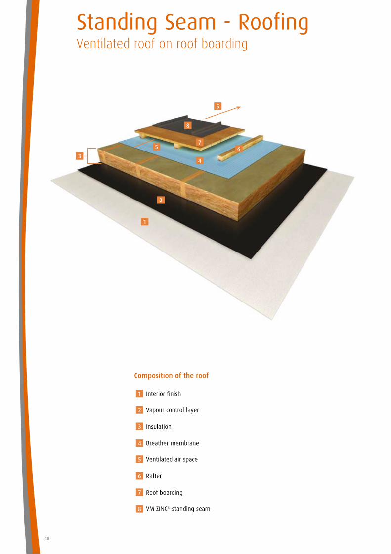
Standing Seam - RoofingVentilated roof on roof boarding
Composition of the roof
Interior finish
Vapour control layer
Insulation
Breather membrane
Ventilated air space
Rafter
Roof boarding
VM ZINC® standing seam
Arch. M + W Pearce - Natural VM ZINC®
1
2
3
4
5
6
7
8
1
2
4
67
8
5
5
48
3
49
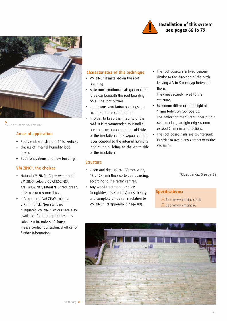
roof boarding
Characteristics of this technique • VM ZINC® is installed on the roof
boarding.
• A 40 mm* continuous air gap must be
left clear beneath the roof boarding,
on all the roof pitches.
• Continuous ventilation openings are
made at the top and bottom.
• In order to keep the integrity of the
roof, it is recommended to install a
breather membrane on the cold side
of the insulation and a vapour control
layer adapted to the internal humidity
load of the building, on the warm side
of the insulation.
Structure
• Clean and dry 100 to 150 mm wide,
18 or 24 mm thick softwood boarding,
according to the rafter centres.
• Any wood treatment products
(fungicides, insecticides) must be dry
and completely neutral in relation to
VM ZINC® (cf appendix 6 page 80).
Areas of application
• Roofs with a pitch from 3° to vertical.
• Classes of internal humidity load:
1 to 4.
• Both renovations and new buildings.
VM ZINC®, the choices
• Natural VM ZINC®, 5 pre-weathered
VM ZINC® colours QUARTZ-ZINC®,
ANTHRA-ZINC®, PIGMENTO® red, green,
blue: 0.7 or 0.8 mm thick.
• 6 Bilacquered VM ZINC® colours:
0.7 mm thick. Non standard
bilaquered VM ZINC® colours are also
available (for large quantities, any
colour - min. orders 10 Tons).
Please contact our technical office for
further information.
• The roof boards are fixed perpen-
dicular to the direction of the pitch
leaving a 3 to 5 mm gap between
them.
They are securely fixed to the
structure.
• Maximum difference in height of
1 mm between roof boards.
The deflection measured under a rigid
600 mm long straight edge cannot
exceed 2 mm in all directions.
• The roof board nails are countersunk
in order to avoid any contact with the
VM ZINC®.
*Cf. appendix 5 page 79
>
>Arch. M + W Pearce - Natural VM ZINC®
Specifications:
: See www.vmzinc.co.uk
: See www.vmzinc.ie
Installation of this systemsee pages 66 to 79
Fixing clips to be used
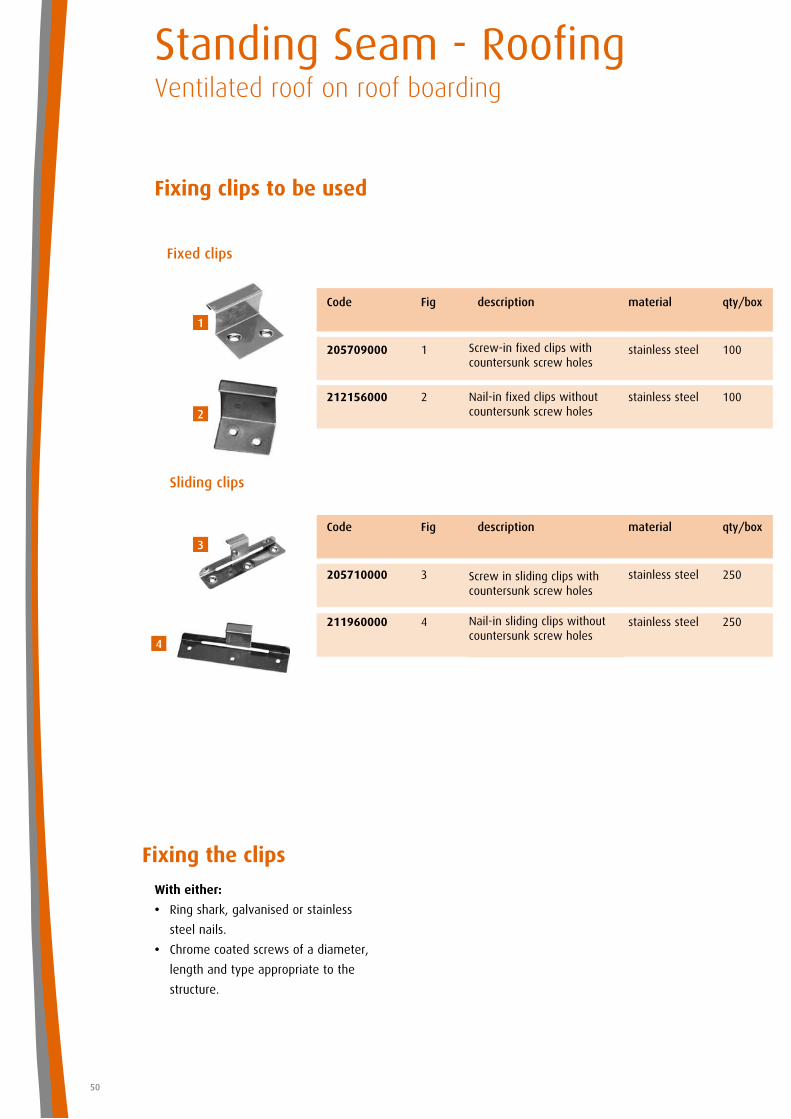
Fixing the clips
With either:
• Ring shark, galvanised or stainless
steel nails.
• Chrome coated screws of a diameter,
length and type appropriate to the
structure.
50
Standing Seam - RoofingVentilated roof on roof boarding
Sliding clips
Fixed clips
Code Fig description material qty/box
205710000 3 stainless steel 250
211960000 4 stainless steel 250Nail-in sliding clips without countersunk screw holes
Screw in sliding clips with countersunk screw holes
Code Fig description material qty/box
205709000 1 stainless steel 100
212156000 2 stainless steel 100Nail-in fixed clips without countersunk screw holes
Screw-in fixed clips with countersunk screw holes
4
3
2
1
51
The solutions presented here are simply examples and are not the only possibilities.
Our technical assistance department is available to study other alternatives with you.
pitch min. 1°
pitch min. 1°
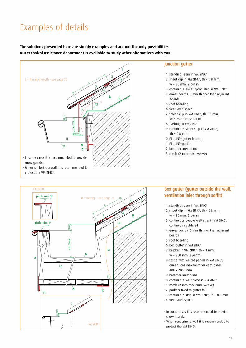
Junction gutter
1. standing seam in VM ZINC®
2. sheet clip in VM ZINC®, th = 0.8 mm,
w = 80 mm, 2 per m
3. continuous eaves apron strip in VM ZINC®
4. eaves boards, 5 mm thinner than adjacent
boards
5. roof boarding
6. ventilated space
7. folded clip in VM ZINC®, th = 1 mm,
w = 250 mm, 2 per m
8. flashing in VM ZINC®
9. continuous sheet strip in VM ZINC®,
th = 0.8 mm
10. PLULINE® gutter bracket
11. PLULINE® gutter
12. breather membrane
13. mesh (2 mm max. weave)
L = Flashing length - see page 76
Box gutter (gutter outside the wall, ventilation inlet through soffit)
1. standing seam in VM ZINC®
2. sheet clip in VM ZINC®, th = 0.8 mm,
w = 80 mm, 2 per m
3. continuous double welt strip in VM ZINC®,
continously soldered
4. eaves boards, 5 mm thinner than adjacent
boards
5. roof boarding
6. box gutter in VM ZINC®
7. bracket in VM ZINC®, th = 1 mm,
w = 250 mm, 2 per m
8. fascia with welted panels in VM ZINC®,
dimensions maximum for each panel:
400 x 2000 mm
9. breather membrane
10. continuous welt piece in VM ZINC®
11. mesh (2 mm maximum weave)
12. packers fixed to gutter fall
13. continuous strip in VM ZINC®, th = 0.8 mm
14. ventilated space
- In some cases it is recommended to provide
snow guards.
- When rendering a wall it is recommended to
protect the VM ZINC®.
R = overlap - see page 76
- In some cases it is recommended to provide
snow guards.
- When rendering a wall it is recommended to
protect the VM ZINC®.
Examples of details
Variation
Variation
pitch min. 1°
pitch min. 1°
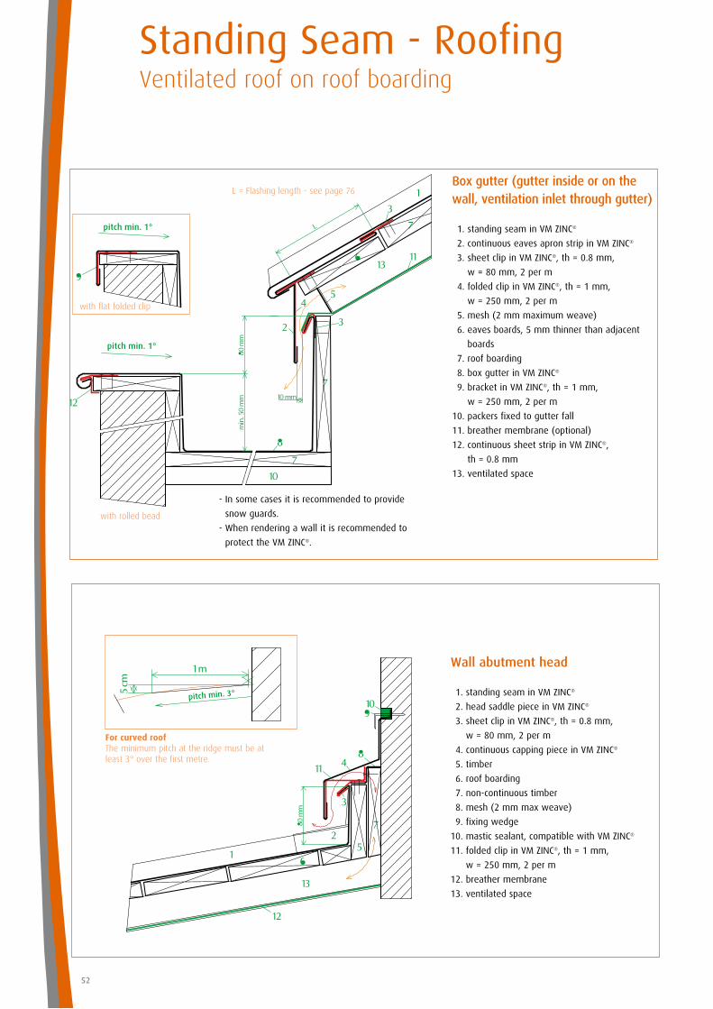
Box gutter (gutter inside or on the wall, ventilation inlet through gutter)
1. standing seam in VM ZINC®
2. continuous eaves apron strip in VM ZINC®
3. sheet clip in VM ZINC®, th = 0.8 mm,
w = 80 mm, 2 per m
4. folded clip in VM ZINC®, th = 1 mm,
w = 250 mm, 2 per m
5. mesh (2 mm maximum weave)
6. eaves boards, 5 mm thinner than adjacent
boards
7. roof boarding
8. box gutter in VM ZINC®
9. bracket in VM ZINC®, th = 1 mm,
w = 250 mm, 2 per m
10. packers fixed to gutter fall
11. breather membrane (optional)
12. continuous sheet strip in VM ZINC®,
th = 0.8 mm
13. ventilated space
- In some cases it is recommended to provide
snow guards.
- When rendering a wall it is recommended to
protect the VM ZINC®.
L = Flashing length - see page 76
Standing Seam - RoofingVentilated roof on roof boarding
52
with flat folded clip
with rolled bead
pitch min. 3°
Wall abutment head
1. standing seam in VM ZINC®
2. head saddle piece in VM ZINC®
3. sheet clip in VM ZINC®, th = 0.8 mm,
w = 80 mm, 2 per m
4. continuous capping piece in VM ZINC®
5. timber
6. roof boarding
7. non-continuous timber
8. mesh (2 mm max weave)
9. fixing wedge
10. mastic sealant, compatible with VM ZINC®
11. folded clip in VM ZINC®, th = 1 mm,
w = 250 mm, 2 per m
12. breather membrane
13. ventilated space
For curved roof The minimum pitch at the ridge must be at least 3° over the first metre.
pitch min. 3°
53
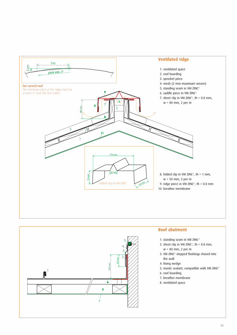
Roof abutment
1. standing seam in VM ZINC®
2. sheet clip in VM ZINC®, th = 0.8 mm,
w = 80 mm, 2 per m
3. VM ZINC® stepped flashings chased into
the wall
4. fixing wedge
5. mastic sealant, compatible with VM ZINC®
6. roof boarding
7. breather membrane
8. ventilated space
Ventilated ridge
1. ventilated space
2. roof boarding
3. sprocket piece
4. mesh (2 mm maximum weave)
5. standing seam in VM ZINC®
6. saddle piece in VM ZINC®
7. sheet clip in VM ZINC®, th = 0.8 mm,
w = 80 mm, 2 per m
8. folded clip in VM ZINC®, th = 1 mm,
w = 50 mm, 3 per m
9. ridge piece in VM ZINC®, th = 0.8 mm
10. breather membrane
Folded clip in VM ZINC®
For curved roof The minimum pitch at the ridge must be at least 3° over the first metre.
Standing Seam - RoofingVentilated roof on roof boarding
54
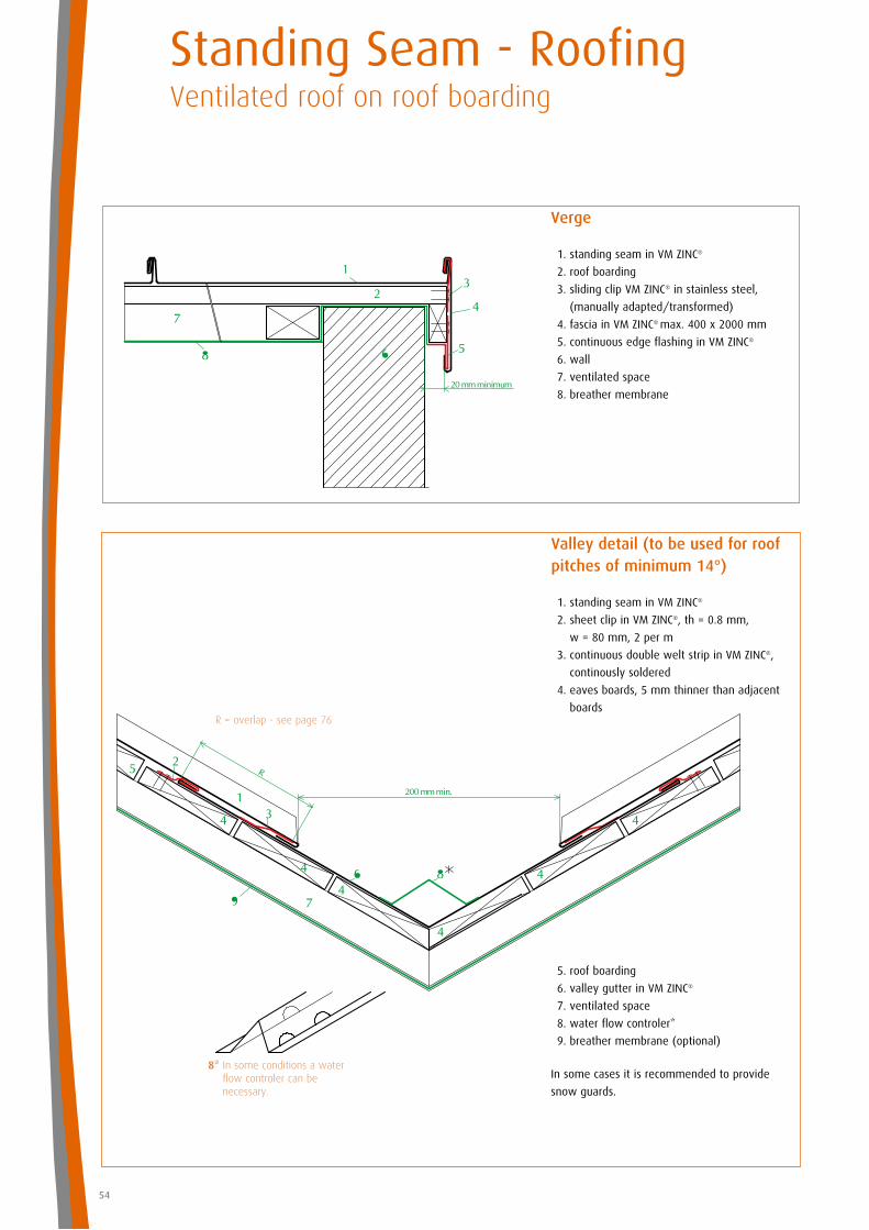
Valley detail (to be used for roofpitches of minimum 14°)
1. standing seam in VM ZINC®
2. sheet clip in VM ZINC®, th = 0.8 mm,
w = 80 mm, 2 per m
3. continuous double welt strip in VM ZINC®,
continously soldered
4. eaves boards, 5 mm thinner than adjacent
boards
5. roof boarding
6. valley gutter in VM ZINC®
7. ventilated space
8. water flow controler*
9. breather membrane (optional)
8* In some conditions a water flow controler can be necessary.
Verge
1. standing seam in VM ZINC®
2. roof boarding
3. sliding clip VM ZINC® in stainless steel,
(manually adapted/transformed)
4. fascia in VM ZINC® max. 400 x 2000 mm
5. continuous edge flashing in VM ZINC®
6. wall
7. ventilated space
8. breather membrane
In some cases it is recommended to provide
snow guards.
R = overlap - see page 76
55
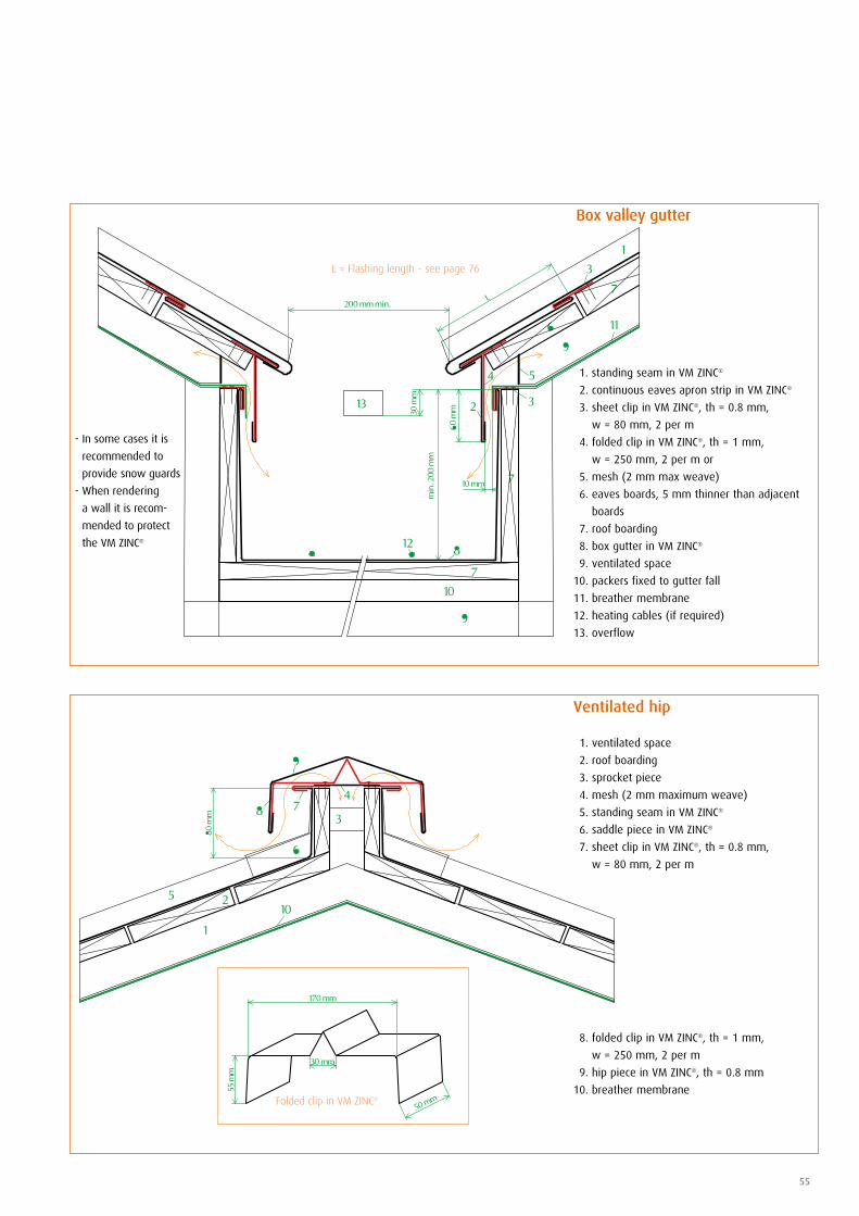
- In some cases it is
recommended to
provide snow guards
- When rendering
a wall it is recom-
mended to protect
the VM ZINC®
Ventilated hip
1. ventilated space
2. roof boarding
3. sprocket piece
4. mesh (2 mm maximum weave)
5. standing seam in VM ZINC®
6. saddle piece in VM ZINC®
7. sheet clip in VM ZINC®, th = 0.8 mm,
w = 80 mm, 2 per m
8. folded clip in VM ZINC®, th = 1 mm,
w = 250 mm, 2 per m
9. hip piece in VM ZINC®, th = 0.8 mm
10. breather membrane Folded clip in VM ZINC®
Box valley gutter
1. standing seam in VM ZINC®
2. continuous eaves apron strip in VM ZINC®
3. sheet clip in VM ZINC®, th = 0.8 mm,
w = 80 mm, 2 per m
4. folded clip in VM ZINC®, th = 1 mm,
w = 250 mm, 2 per m or
5. mesh (2 mm max weave)
6. eaves boards, 5 mm thinner than adjacent
boards
7. roof boarding
8. box gutter in VM ZINC®
9. ventilated space
10. packers fixed to gutter fall
11. breather membrane
12. heating cables (if required)
13. overflow
L = Flashing length - see page 76
section CC
section AA
section DD
section BB
saddle piece
continuous welting strip
skylight
standing seam in VM ZINC® independent flashing
5
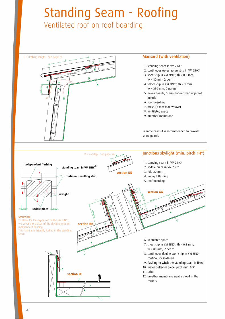
Junctions skylight (min. pitch 14°)
1. standing seam in VM ZINC®
2. saddle piece in VM ZINC®
3. fold 20 mm
4. skylight flashing
5. roof boarding
6. ventilated space
7. sheet clip in VM ZINC®, th = 0.8 mm,
w = 80 mm, 2 per m
8. continuous double welt strip in VM ZINC®,
continously soldered
9. flashing to witch the standing seam is fixed
10. water deflector piece, pitch min. 0.5°
11. rafter
12. breather membrane neatly glued in the
corners
Overview To allow for the expansion of the VM ZINC®, we cover the chassis of the skylight with an independent flashing.This flashing is laterally locked in the standing seam.
Mansard (with ventilation)
1. standing seam in VM ZINC®
2. continuous eaves apron strip in VM ZINC®
3. sheet clip in VM ZINC®, th = 0.8 mm,
w = 80 mm, 2 per m
4. folded clip in VM ZINC®, th = 1 mm,
w = 250 mm, 2 per m
5. eaves boards, 5 mm thinner than adjacent
boards
6. roof boarding
7. mesh (2 mm max weave)
8. ventilated space
9. breather membrane
R = overlap - see page 76
In some cases it is recommended to provide
snow guards.
L = Flashing length - see page 76
Standing Seam - RoofingVentilated roof on roof boarding
56
10
10
57
standing seam in VM ZINC®
laid seam, soldered continuously
section CC
section AA
saddle piece
skylight
section BB
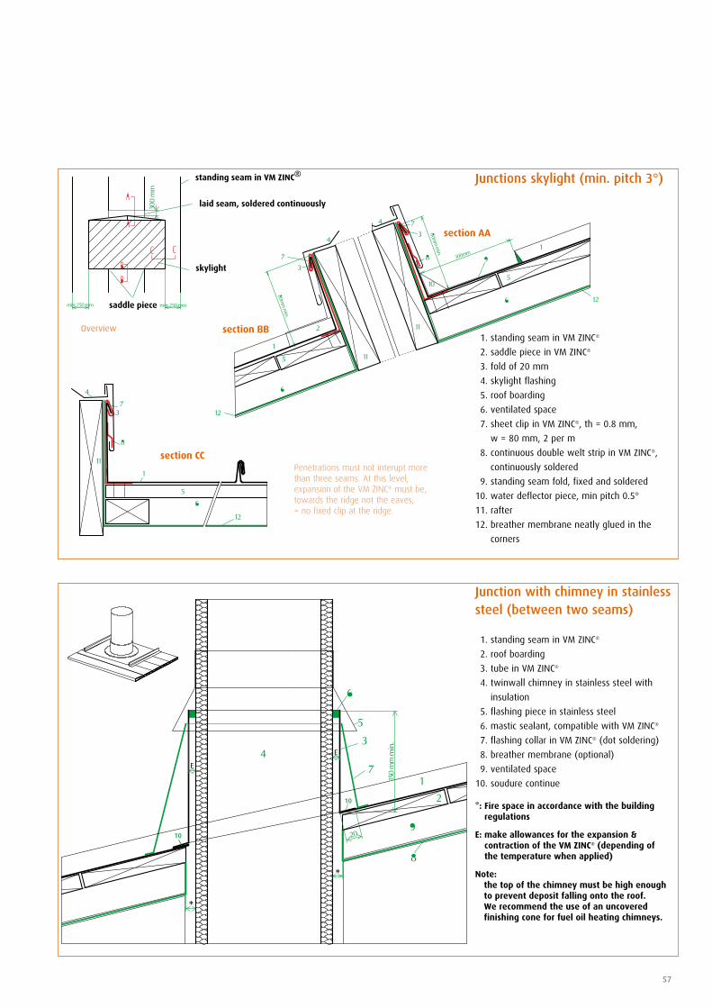
Junction with chimney in stainless steel (between two seams)
1. standing seam in VM ZINC®
2. roof boarding
3. tube in VM ZINC®
4. twinwall chimney in stainless steel with
insulation
5. flashing piece in stainless steel
6. mastic sealant, compatible with VM ZINC®
7. flashing collar in VM ZINC® (dot soldering)
8. breather membrane (optional)
9. ventilated space
10. soudure continue
Junctions skylight (min. pitch 3°)
1. standing seam in VM ZINC®
2. saddle piece in VM ZINC®
3. fold of 20 mm
4. skylight flashing
5. roof boarding
6. ventilated space
7. sheet clip in VM ZINC®, th = 0.8 mm,
w = 80 mm, 2 per m
8. continuous double welt strip in VM ZINC®,
continuously soldered
9. standing seam fold, fixed and soldered
10. water deflector piece, min pitch 0.5°
11. rafter
12. breather membrane neatly glued in the
corners
Penetrations must not interupt more than three seams. At this level, expansion of the VM ZINC® must be, towards the ridge not the eaves, = no fixed clip at the ridge.
*: Fire space in accordance with the building regulations
E: make allowances for the expansion & contraction of the VM ZINC® (depending of the temperature when applied)
Note: the top of the chimney must be high enough
to prevent deposit falling onto the roof. We recommend the use of an uncovered finishing cone for fuel oil heating chimneys.
Overview
pitch min. 3°
see joint detail
pitch min. 1°
58
• In order to keep the integrity of the
roof, it is recommended to install a
breather membrane on the cold side
of the insulation and a vapour control
layer adapted to the internal humidity
load of the building, on the warm side
of the insulation.
Structure
See structure recommendations
on page 9.
*Cf. appendix 5 page 79
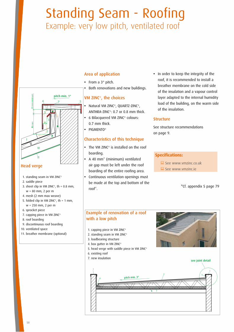
Area of application
• From a 3° pitch.
• Both renovations and new buildings.
VM ZINC®, the choices
• Natural VM ZINC®, QUARTZ-ZINC®,
ANTHRA-ZINC®: 0.7 or 0.8 mm thick.
• 6 Bilacquered VM ZINC® colours:
0.7 mm thick.
• PIGMENTO®
Characteristics of this technique
• The VM ZINC® is installed on the roof
boarding.
• A 40 mm* (minimum) ventilated
air gap must be left under the roof
boarding of the entire roofing area.
• Continuous ventilation openings must
be made at the top and bottom of the
roof*.
Head verge
1. standing seam in VM ZINC®
2. saddle piece
3. sheet clip in VM ZINC®, th = 0.8 mm,
w = 80 mm, 2 per m
4. mesh (2 mm max weave)
5. folded clip in VM ZINC®, th = 1 mm,
w = 250 mm, 2 per m
6. sprocket piece
7. capping piece in VM ZINC®
8. roof boarding
9. discontinuous roof boarding
10. ventilated space
11. breather membrane (optional)
Standing Seam - RoofingExample: very low pitch, ventilated roof
Example of renovation of a roof with a low pitch
1. capping piece in VM ZINC®
2. standing seam in VM ZINC®
3. loadbearing structure
4. box gutter in VM ZINC®
5. head verge with saddle piece in VM ZINC®
6. existing roof
7. new insulation
Specifications:
: See www.vmzinc.co.uk
: See www.vmzinc.ie
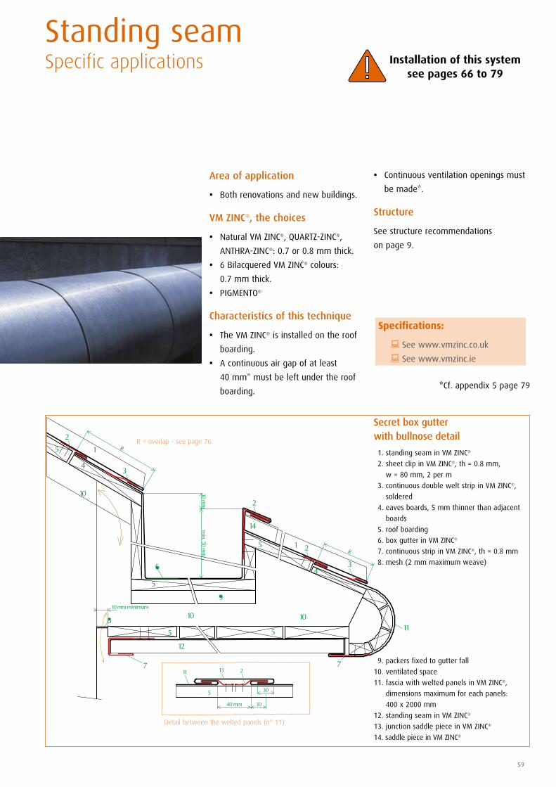
• Continuous ventilation openings must
be made*.
Structure
See structure recommendations
on page 9.
*Cf. appendix 5 page 79
59
Area of application
• Both renovations and new buildings.
VM ZINC®, the choices
• Natural VM ZINC®, QUARTZ-ZINC®,
ANTHRA-ZINC®: 0.7 or 0.8 mm thick.
• 6 Bilacquered VM ZINC® colours:
0.7 mm thick.
• PIGMENTO®
Characteristics of this technique
• The VM ZINC® is installed on the roof
boarding.
• A continuous air gap of at least
40 mm* must be left under the roof
boarding.
Standing seam Specific applications
Secret box gutter with bullnose detail
1. standing seam in VM ZINC®
2. sheet clip in VM ZINC®, th = 0.8 mm,
w = 80 mm, 2 per m
3. continuous double welt strip in VM ZINC®,
soldered
4. eaves boards, 5 mm thinner than adjacent
boards
5. roof boarding
6. box gutter in VM ZINC®
7. continuous strip in VM ZINC®, th = 0.8 mm
8. mesh (2 mm maximum weave)
9. packers fixed to gutter fall
10. ventilated space
11. fascia with welted panels in VM ZINC®,
dimensions maximum for each panels:
400 x 2000 mm
12. standing seam in VM ZINC®
13. junction saddle piece in VM ZINC®
14. saddle piece in VM ZINC®
R = overlap - see page 76
Detail between the welted panels (n° 11).
Installation of this system see pages 66 to 79
Specifications:
: See www.vmzinc.co.uk
: See www.vmzinc.ie
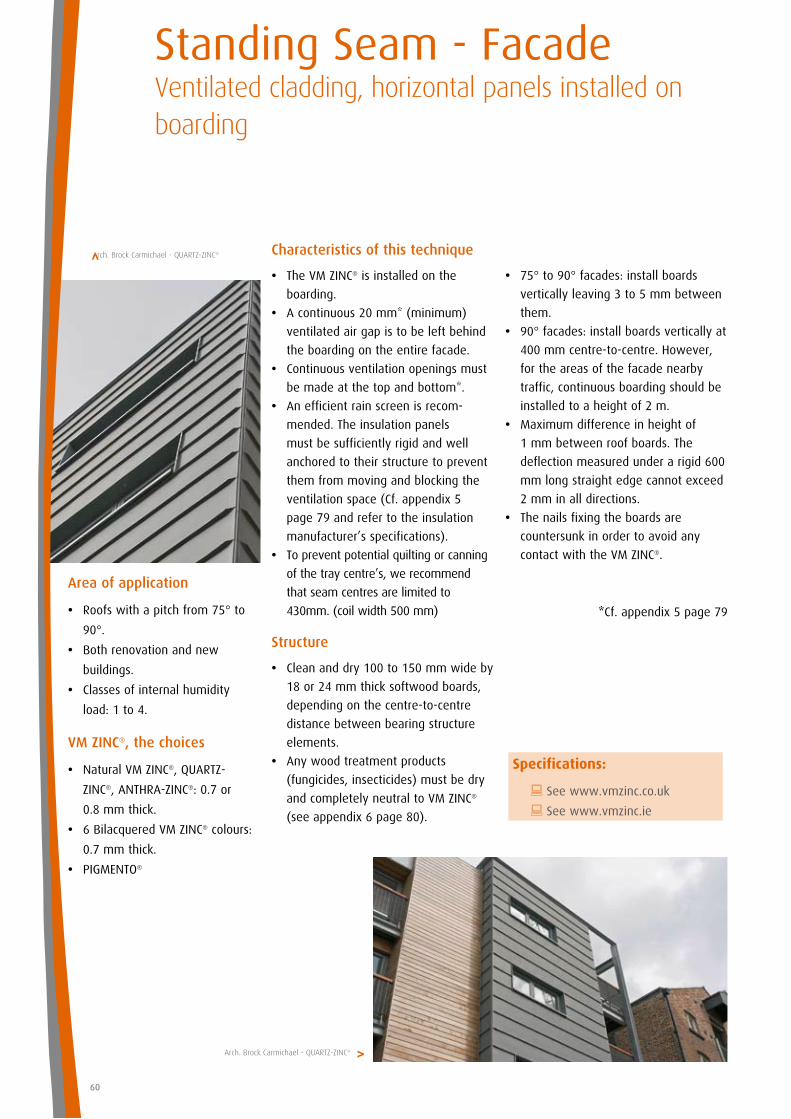
Standing Seam - FacadeVentilated cladding, horizontal panels installed on boarding
Characteristics of this technique
• The VM ZINC® is installed on the
boarding.
• A continuous 20 mm* (minimum)
ventilated air gap is to be left behind
the boarding on the entire facade.
• Continuous ventilation openings must
be made at the top and bottom*.
• An efficient rain screen is recom-
mended. The insulation panels
must be sufficiently rigid and well
anchored to their structure to prevent
them from moving and blocking the
ventilation space (Cf. appendix 5
page 79 and refer to the insulation
manufacturer’s specifications).
• To prevent potential quilting or canning
of the tray centre’s, we recommend
that seam centres are limited to
430mm. (coil width 500 mm)
Structure
• Clean and dry 100 to 150 mm wide by
18 or 24 mm thick softwood boards,
depending on the centre-to-centre
distance between bearing structure
elements.
• Any wood treatment products
(fungicides, insecticides) must be dry
and completely neutral to VM ZINC®
(see appendix 6 page 80).
Area of application
• Roofs with a pitch from 75° to
90°.
• Both renovation and new
buildings.
• Classes of internal humidity
load: 1 to 4.
VM ZINC®, the choices
• Natural VM ZINC®, QUARTZ-
ZINC®, ANTHRA-ZINC®: 0.7 or
0.8 mm thick.
• 6 Bilacquered VM ZINC® colours:
0.7 mm thick.
• PIGMENTO®
• 75° to 90° facades: install boards
vertically leaving 3 to 5 mm between
them.
• 90° facades: install boards vertically at
400 mm centre-to-centre. However,
for the areas of the facade nearby
traffic, continuous boarding should be
installed to a height of 2 m.
• Maximum difference in height of
1 mm between roof boards. The
deflection measured under a rigid 600
mm long straight edge cannot exceed
2 mm in all directions.
• The nails fixing the boards are
countersunk in order to avoid any
contact with the VM ZINC®.
*Cf. appendix 5 page 79
60
Arch. Brock Carmichael - QUARTZ-ZINC®>
Arch. Brock Carmichael - QUARTZ-ZINC®>
Specifications:
: See www.vmzinc.co.uk
: See www.vmzinc.ie
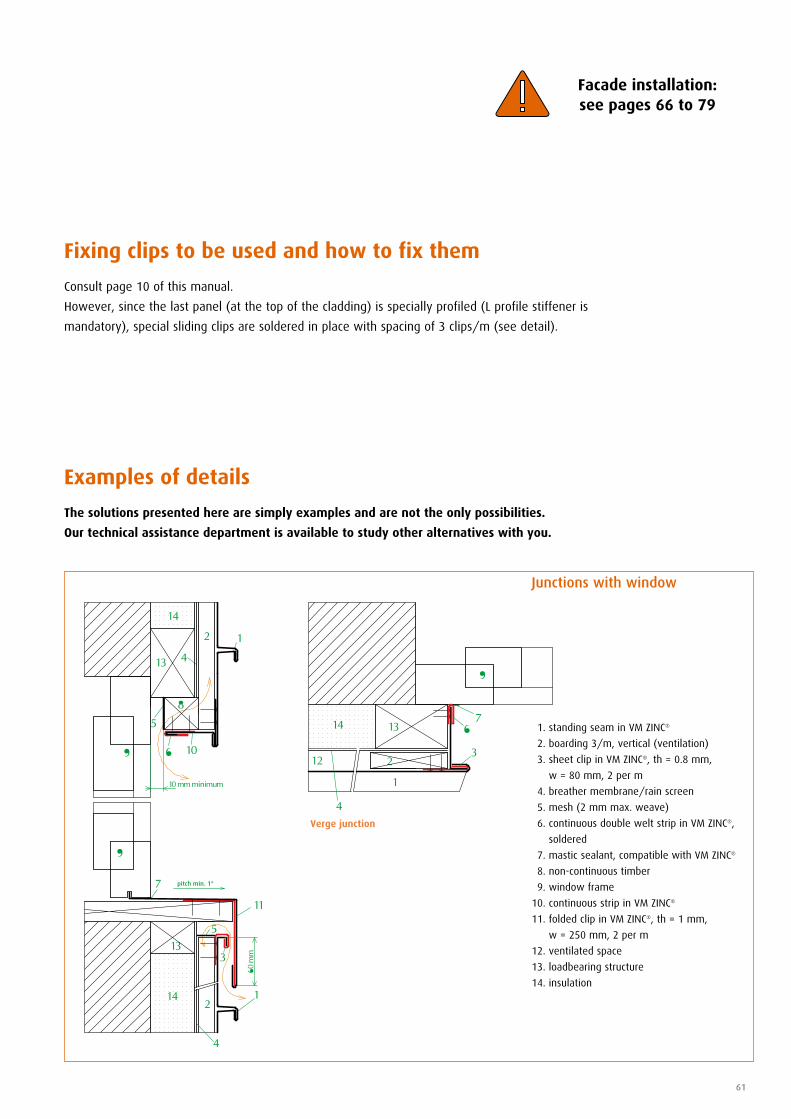
pitch min. 1°
61
Fixing clips to be used and how to fix them
Examples of details
The solutions presented here are simply examples and are not the only possibilities.
Our technical assistance department is available to study other alternatives with you.
Consult page 10 of this manual.
However, since the last panel (at the top of the cladding) is specially profiled (L profile stiffener is
mandatory), special sliding clips are soldered in place with spacing of 3 clips/m (see detail).
Junctions with window
1. standing seam in VM ZINC®
2. boarding 3/m, vertical (ventilation)
3. sheet clip in VM ZINC®, th = 0.8 mm,
w = 80 mm, 2 per m
4. breather membrane/rain screen
5. mesh (2 mm max. weave)
6. continuous double welt strip in VM ZINC®,
soldered
7. mastic sealant, compatible with VM ZINC®
8. non-continuous timber
9. window frame
10. continuous strip in VM ZINC®
11. folded clip in VM ZINC®, th = 1 mm,
w = 250 mm, 2 per m
12. ventilated space
13. loadbearing structure
14. insulation
Facade installation: see pages 66 to 79
Verge junction

pitch min. 1°
pitch min. 1°
62
End of cladding
1. standing seam in VM ZINC®
2. edge flashing in VM ZINC®
3. mesh (2 mm max weave)
4. vertical boarding 3/m (ventilation)
5. loadbearing structure
6. breather membrane/rain screen (optional)
7. capping piece in VM ZINC®
8. sheet clip in VM ZINC®, th = 0.8 mm,
w = 80 mm, 2 per m
9. folded clip in VM ZINC®, th = 1 mm,
w = 250 mm, 2 per m
10. continuous strip in VM ZINC®
11. insulation
Standing Seam - FacadeVentilated cladding, horizontal panels installed on boarding
Head cladding
1. standing seam in VM ZINC®
2. sheet clip in VM ZINC®, th = 0.8 mm,
w = 80 mm, 2 per m
3. mesh (2 mm max. weave)
4. folded clip in VM ZINC®, th = 1 mm,
w = 250 mm, 2 per m
5. capping piece in VM ZINC®
6. vertical boarding 3/m (ventilation)
7. loadbearing structure
8. bituminous membrane
9. breather membrane/rain screen (optional)
10. insulation
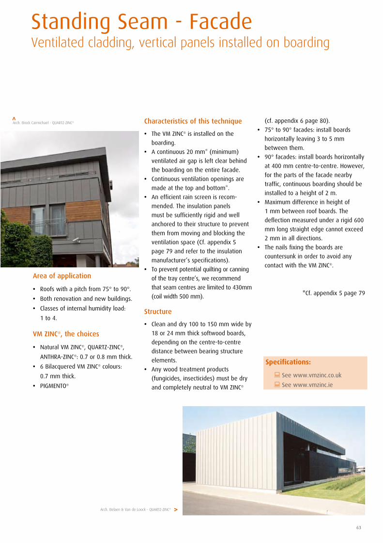
63
Characteristics of this technique
• The VM ZINC® is installed on the
boarding.
• A continuous 20 mm* (minimum)
ventilated air gap is left clear behind
the boarding on the entire facade.
• Continuous ventilation openings are
made at the top and bottom*.
• An efficient rain screen is recom-
mended. The insulation panels
must be sufficiently rigid and well
anchored to their structure to prevent
them from moving and blocking the
ventilation space (Cf. appendix 5
page 79 and refer to the insulation
manufacturer’s specifications).
• To prevent potential quilting or canning
of the tray centre’s, we recommend
that seam centres are limited to 430mm
(coil width 500 mm).
Structure
• Clean and dry 100 to 150 mm wide by
18 or 24 mm thick softwood boards,
depending on the centre-to-centre
distance between bearing structure
elements.
• Any wood treatment products
(fungicides, insecticides) must be dry
and completely neutral to VM ZINC®
Area of application
• Roofs with a pitch from 75° to 90°.
• Both renovation and new buildings.
• Classes of internal humidity load:
1 to 4.
VM ZINC®, the choices
• Natural VM ZINC®, QUARTZ-ZINC®,
ANTHRA-ZINC®: 0.7 or 0.8 mm thick.
• 6 Bilacquered VM ZINC® colours:
0.7 mm thick.
• PIGMENTO®
(cf. appendix 6 page 80).
• 75° to 90° facades: install boards
horizontally leaving 3 to 5 mm
between them.
• 90° facades: install boards horizontally
at 400 mm centre-to-centre. However,
for the parts of the facade nearby
traffic, continuous boarding should be
installed to a height of 2 m.
• Maximum difference in height of
1 mm between roof boards. The
deflection measured under a rigid 600
mm long straight edge cannot exceed
2 mm in all directions.
• The nails fixing the boards are
countersunk in order to avoid any
contact with the VM ZINC®.
*Cf. appendix 5 page 79
Standing Seam - FacadeVentilated cladding, vertical panels installed on boarding
Arch. Belaen & Van de Loock - QUARTZ-ZINC®
Arch. Brock Carmichael - QUARTZ-ZINC®>
>
Specifications:
: See www.vmzinc.co.uk
: See www.vmzinc.ie
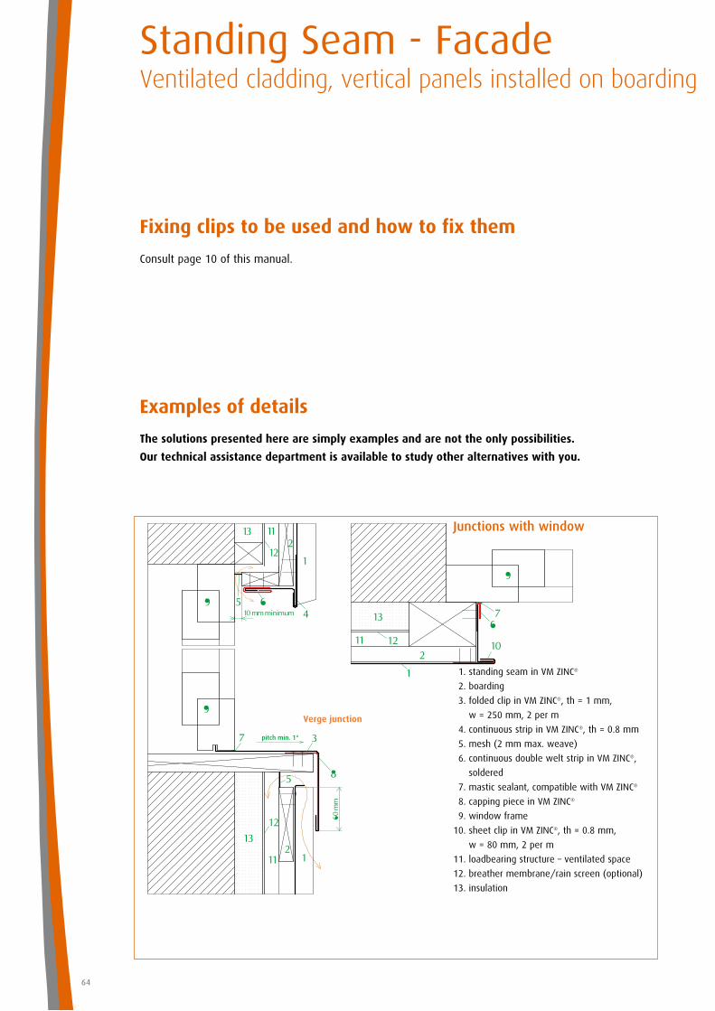
pitch min. 1°
64
Fixing clips to be used and how to fix them
Examples of details
The solutions presented here are simply examples and are not the only possibilities.
Our technical assistance department is available to study other alternatives with you.
Consult page 10 of this manual.
Standing Seam - FacadeVentilated cladding, vertical panels installed on boarding
Junctions with window
1. standing seam in VM ZINC®
2. boarding
3. folded clip in VM ZINC®, th = 1 mm,
w = 250 mm, 2 per m
4. continuous strip in VM ZINC®, th = 0.8 mm
5. mesh (2 mm max. weave)
6. continuous double welt strip in VM ZINC®,
soldered
7. mastic sealant, compatible with VM ZINC®
8. capping piece in VM ZINC®
9. window frame
10. sheet clip in VM ZINC®, th = 0.8 mm,
w = 80 mm, 2 per m
11. loadbearing structure – ventilated space
12. breather membrane/rain screen (optional)
13. insulation
Verge junction

pitch min. 1°
pitch min. 1°
65
End of cladding
1. standing seam in VM ZINC®
2. continuous edge flashing in VM ZINC®
3. sheet clip in VM ZINC®, th = 0.8 mm,
w = 80 mm, 2 per m
4. folded clip in VM ZINC®, th = 1 mm,
w = 250 mm, 2 per m
5. capping piece in VM ZINC®
6. boarding
7. mesh (max. gap size 2 mm)
8. ventilated space
9. breather membrane/rain screen (optional)
10. insulation
Head cladding
1. standing seam in VM ZINC®
2. boarding
3. mesh (max. gap size 2 mm)
4. folded clip in VM ZINC®, th = 1 mm,
w = 250 mm, 2 per m
5. capping piece in VM ZINC®
6. bituminous membrane
7. ventilated space
8. breather membrane/rain screen (optional)
9. insulation
Standing Seam - FacadeVentilated cladding, vertical panels installed on boarding

standing seam530 mm
(1) (1)
Standing seamSystem installation - General Information
Umicore organises practical training courses on the installation of VM ZINC® standing seam:
•Reserved for roofing professionals.•Organised in a covered, specially equipped training centre.
www.vmzinc.co.uk
www.vmzinc.ie
01992 822288
Expansion of VM ZINC®
Any work involving VM ZINC® must allow it to expand and contract freely. The linear expansion of VM ZINC®
is 0.022 mm per metre and per degree centigrade.
Example:
In United Kingdom and the Republic of Ireland, the temperature range to bear in mind is from – 20°C in
mid-winter to + 80°C on the surface of the metal in the sun at the height of the summer. Assuming an
ambient temperature of 20°C during installation, we have to take into account:
• An additional 60°C (expansion)
• 40°C less (contraction).
For a 10 metre long panel:
• anticipate an 0.022 mm x 10 x 60 = 13.2 mm increase in length
• anticipate 0.022 mm x 10 x 40 = 8.8 mm contraction.
Layout
either:
• a joint on the central axis of the
surface to be covered.
• the middle of a sheet on the central
axis of the element to be covered.
Dormers, chimneys or other obstacles
must be taken into account before
deciding layout.
(1) see page 67.
standing seam
(1) (1)
66
surface to be covered
surface to be covered
Off-centre layout
Layout centred on axis – section
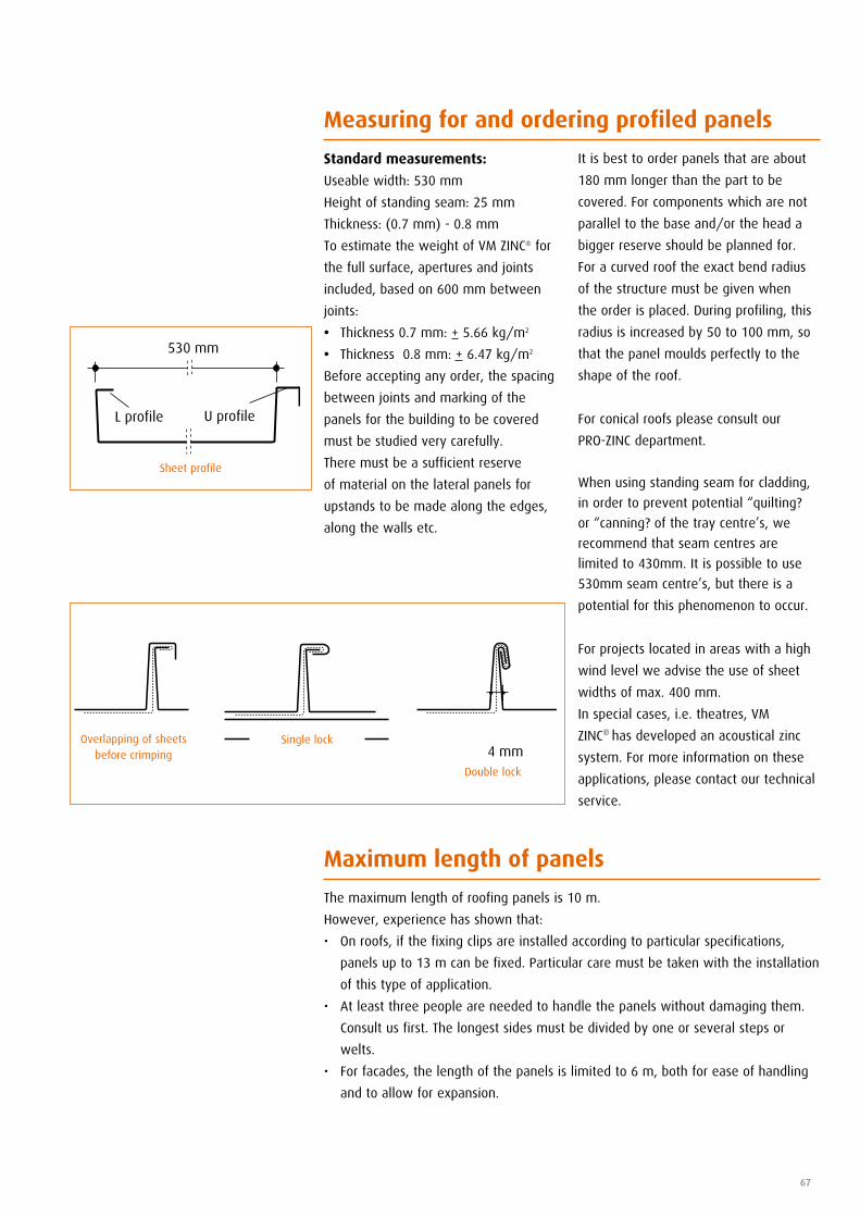
67
Measuring for and ordering profiled panels
Standard measurements:
Useable width: 530 mm
Height of standing seam: 25 mm
Thickness: (0.7 mm) - 0.8 mm
To estimate the weight of VM ZINC® for
the full surface, apertures and joints
included, based on 600 mm between
joints:
• Thickness 0.7 mm: + 5.66 kg/m2
• Thickness 0.8 mm: + 6.47 kg/m2
Before accepting any order, the spacing
between joints and marking of the
panels for the building to be covered
must be studied very carefully.
There must be a sufficient reserve
of material on the lateral panels for
upstands to be made along the edges,
along the walls etc.
It is best to order panels that are about
180 mm longer than the part to be
covered. For components which are not
parallel to the base and/or the head a
bigger reserve should be planned for.
For a curved roof the exact bend radius
of the structure must be given when
the order is placed. During profiling, this
radius is increased by 50 to 100 mm, so
that the panel moulds perfectly to the
shape of the roof.
For conical roofs please consult our
PRO-ZINC department.
When using standing seam for cladding,
in order to prevent potential “quilting?
or “canning? of the tray centre’s, we
recommend that seam centres are
limited to 430mm. It is possible to use
530mm seam centre’s, but there is a
potential for this phenomenon to occur.
For projects located in areas with a high
wind level we advise the use of sheet
widths of max. 400 mm.
In special cases, i.e. theatres, VM
ZINC® has developed an acoustical zinc
system. For more information on these
applications, please contact our technical
service.
L profile
530 mm
U profile
4 mmOverlapping of sheets
before crimping
Sheet profile
Single lock
Double lock
Maximum length of panels
The maximum length of roofing panels is 10 m.
However, experience has shown that:
• Onroofs,ifthefixingclipsareinstalledaccordingtoparticularspecifications,
panels up to 13 m can be fixed. Particular care must be taken with the installation
of this type of application.
• Atleastthreepeopleareneededtohandlethepanelswithoutdamagingthem.
Consult us first. The longest sides must be divided by one or several steps or
welts.
• Forfacades,thelengthofthepanelsislimitedto6m,bothforeaseofhandling
and to allow for expansion.
68
Transportation and storage of profiled VM ZINC®
The panels must be transported and
stored vertically, standing on the
L profile in containers designed for them.
They must be transported and stored
in dry conditions and in a constant
temperature in order to avoid the
formation of white rust.
White rust forms on the surface of
VM ZINC® when the latter comes in
contact with humidity in the absence
of carbon dioxide. In this case, the
protective passivated layer cannot form
and white rust appears on the surface.
Unlike the patined layer, white rust
provides no protection and leaves
unattractive, indelible marks on the
roof or facade. Consequently, we do not
recommend installing panels that have
been attacked by white rust.
Standing seamSystem installation
Before installation
The roofer must ensure that:
• the structure is dry, clean and
free of any rubbish (nails, leaves,
vegetation, etc.). All the substrates
must be flat, dry, and sufficiently
resistant to all the stresses to which
they will be submitted (e.g. pull out
force of 50daN per standing seam
fixing clip).
Maximum flush tolerance of 1 mm. In
the case of installation on a separation
membrane, the roofer must also make
sure that this is clean and dry.
• Thepanelshavethecorrect
measurements and profiles.
• Thestructureconforms(flatness,
compatibility, etc.) to the
specifications.
Direction of installation
Installation can begin on the right or
the left, regardless of the direction of
prevailing winds. Crimping can be done
either from bottom to top or top to
bottom! Some electric crimping machines
only allow crimping in one direction!
So check before deciding on installation
direction!
Installing VM ZINC®
To avoid micro-cracks in the VM ZINC®
to the right of the folds, do not work
it when the temperature of the metal
is below 7°C.
PIGMENTO requires working specifications
with PIGMENTO are slightly different
Working VM ZINC®
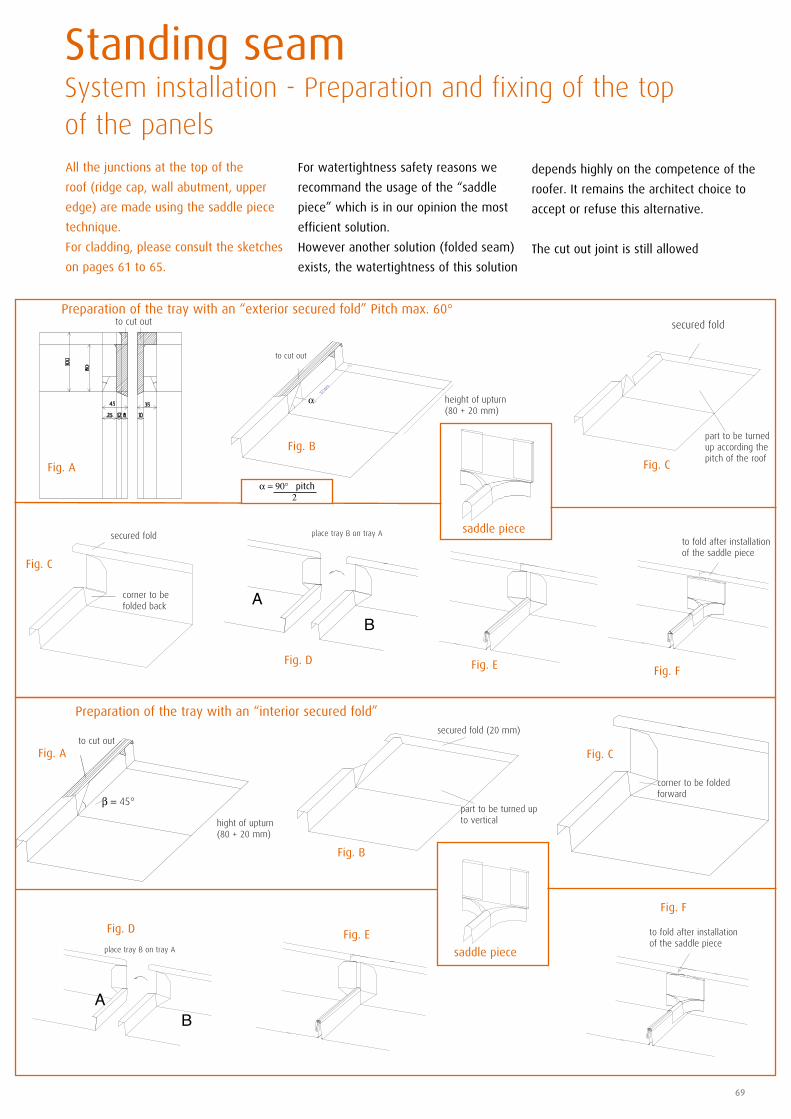
69
All the junctions at the top of the
roof (ridge cap, wall abutment, upper
edge) are made using the saddle piece
technique.
For cladding, please consult the sketches
on pages 61 to 65.
Standing seam System installation - Preparation and fixing of the top of the panels
For watertightness safety reasons we
recommand the usage of the “saddle
piece” which is in our opinion the most
efficient solution.
However another solution (folded seam)
exists, the watertightness of this solution
depends highly on the competence of the
roofer. It remains the architect choice to
accept or refuse this alternative.
The cut out joint is still allowed
Fig. C
Fig. A
Fig. B
Fig. C
Preparation of the tray with an “exterior secured fold” Pitch max. 60°
Preparation of the tray with an “interior secured fold”
Fig. D
saddle piece
Fig. E Fig. F
saddle piece
Fig. D
Fig. F
Fig. E
hight of upturn(80 + 20 mm)
to cut out
β = 45°
place tray B on tray A
BA
to cut out
BA
Fig. A
Fig. B
Fig. C
secured fold
part to be turned up according the pitch of the roof
to fold after installationof the saddle piece
secured fold (20 mm)
part to be turned up to vertical
to fold after installationof the saddle piece
corner to be folded forward
height of upturn(80 + 20 mm)
α
α = 90° - pitch 2
place tray B on tray A
corner to be folded back
secured fold
to cut out
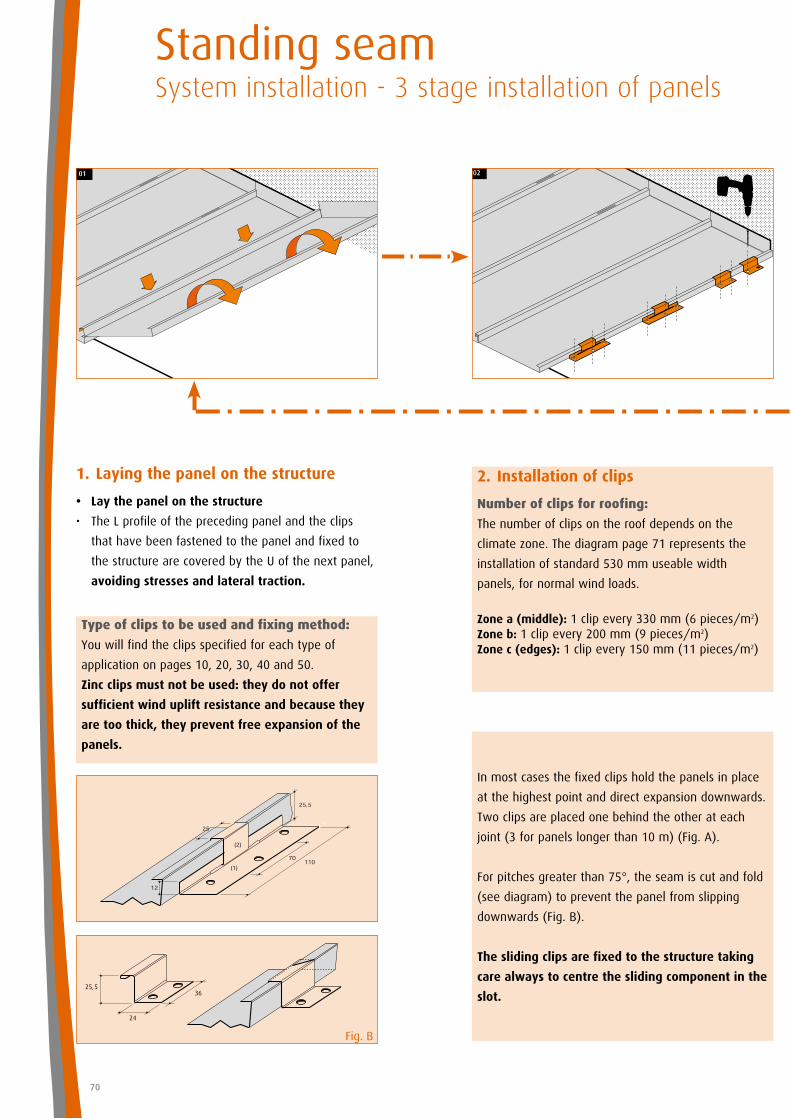
70
36
24
25,5
Type of clips to be used and fixing method:
You will find the clips specified for each type of
application on pages 10, 20, 30, 40 and 50.
Zinc clips must not be used: they do not offer
sufficient wind uplift resistance and because they
are too thick, they prevent free expansion of the
panels.
In most cases the fixed clips hold the panels in place
at the highest point and direct expansion downwards.
Two clips are placed one behind the other at each
joint (3 for panels longer than 10 m) (Fig. A).
For pitches greater than 75°, the seam is cut and fold
(see diagram) to prevent the panel from slipping
downwards (Fig. B).
The sliding clips are fixed to the structure taking
care always to centre the sliding component in the
slot.
Fig. B
Standing seamSystem installation - 3 stage installation of panels
1. Laying the panel on the structure
• Lay the panel on the structure
• TheLprofileoftheprecedingpanelandtheclips
that have been fastened to the panel and fixed to
the structure are covered by the U of the next panel,
avoiding stresses and lateral traction.
2. Installation of clips
Number of clips for roofing:
The number of clips on the roof depends on the
climate zone. The diagram page 71 represents the
installation of standard 530 mm useable width
panels, for normal wind loads.
Zone a (middle): 1 clip every 330 mm (6 pieces/m2)Zone b: 1 clip every 200 mm (9 pieces/m2)Zone c (edges): 1 clip every 150 mm (11 pieces/m2)
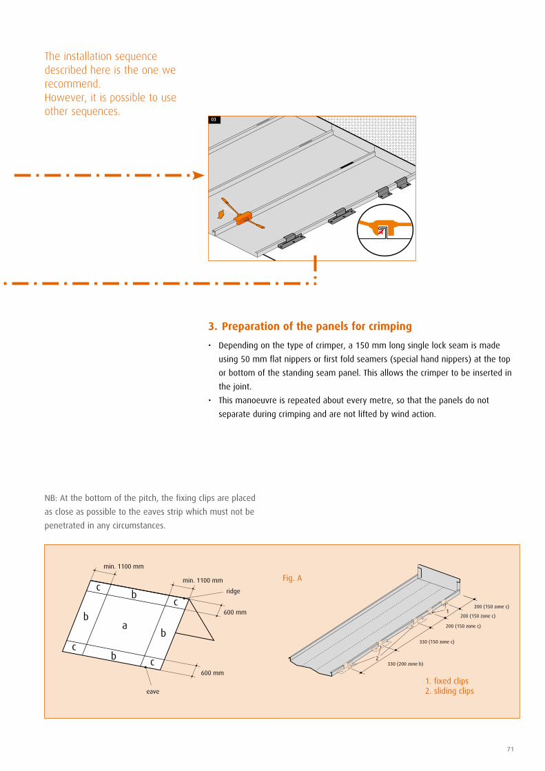
2
1
71
1. fixed clips2. sliding clips
Fig. A
3. Preparation of the panels for crimping
• Dependingonthetypeofcrimper,a150mmlongsinglelockseamismade
using 50 mm flat nippers or first fold seamers (special hand nippers) at the top
or bottom of the standing seam panel. This allows the crimper to be inserted in
the joint.
• Thismanoeuvreisrepeatedabouteverymetre,sothatthepanelsdonot
separate during crimping and are not lifted by wind action.
NB: At the bottom of the pitch, the fixing clips are placed
as close as possible to the eaves strip which must not be
penetrated in any circumstances.
The installation sequence described here is the one we recommend.However, it is possible to use other sequences.
b
b
b
min. 1100 mm
600 mm
600 mm
eave
min. 1100 mm
b
a
c
c
c
c
ridge
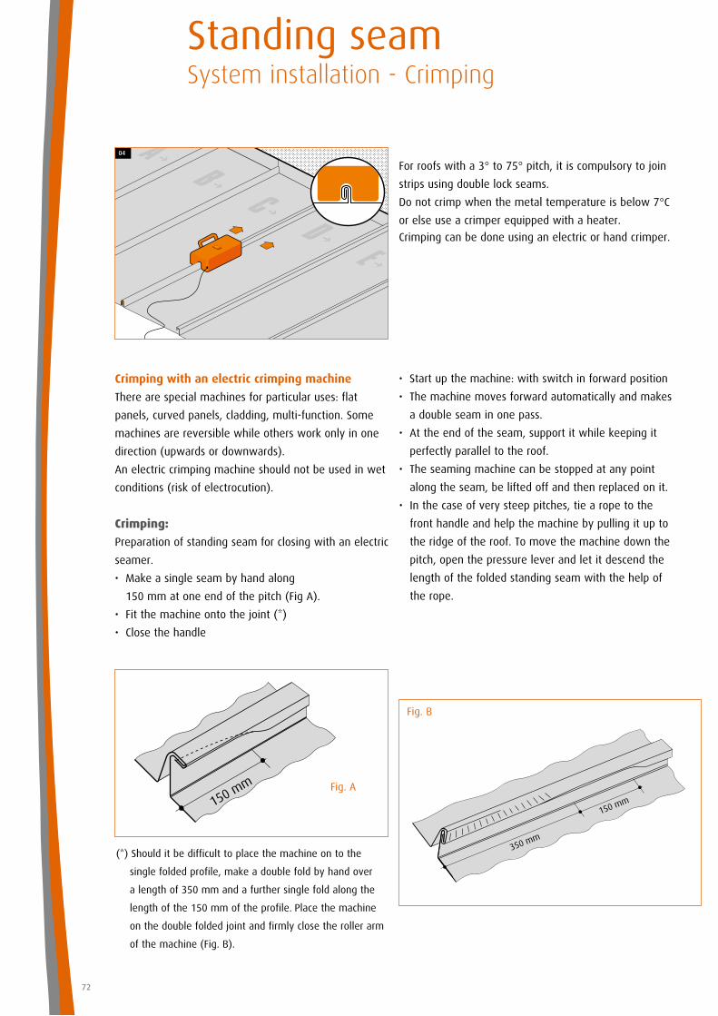
72
Crimping with an electric crimping machine
There are special machines for particular uses: flat
panels, curved panels, cladding, multi-function. Some
machines are reversible while others work only in one
direction (upwards or downwards).
An electric crimping machine should not be used in wet
conditions (risk of electrocution).
Crimping:
Preparation of standing seam for closing with an electric
seamer.
•Makeasingleseambyhandalong
150 mm at one end of the pitch (Fig A).
•Fitthemachineontothejoint(*)
•Closethehandle
For roofs with a 3° to 75° pitch, it is compulsory to join
strips using double lock seams.
Do not crimp when the metal temperature is below 7°C
or else use a crimper equipped with a heater.
Crimping can be done using an electric or hand crimper.
150 mm
(*) Should it be difficult to place the machine on to the
single folded profile, make a double fold by hand over
a length of 350 mm and a further single fold along the
length of the 150 mm of the profile. Place the machine
on the double folded joint and firmly close the roller arm
of the machine (Fig. B).
150 mm
350 mm
Fig. B
Standing seamSystem installation - Crimping
Fig. A
•Startupthemachine:withswitchinforwardposition
•Themachinemovesforwardautomaticallyandmakes
a double seam in one pass.
•Attheendoftheseam,supportitwhilekeepingit
perfectly parallel to the roof.
•Theseamingmachinecanbestoppedatanypoint
along the seam, be lifted off and then replaced on it.
•Inthecaseofverysteeppitches,tiearopetothe
front handle and help the machine by pulling it up to
the ridge of the roof. To move the machine down the
pitch, open the pressure lever and let it descend the
length of the folded standing seam with the help of
the rope.
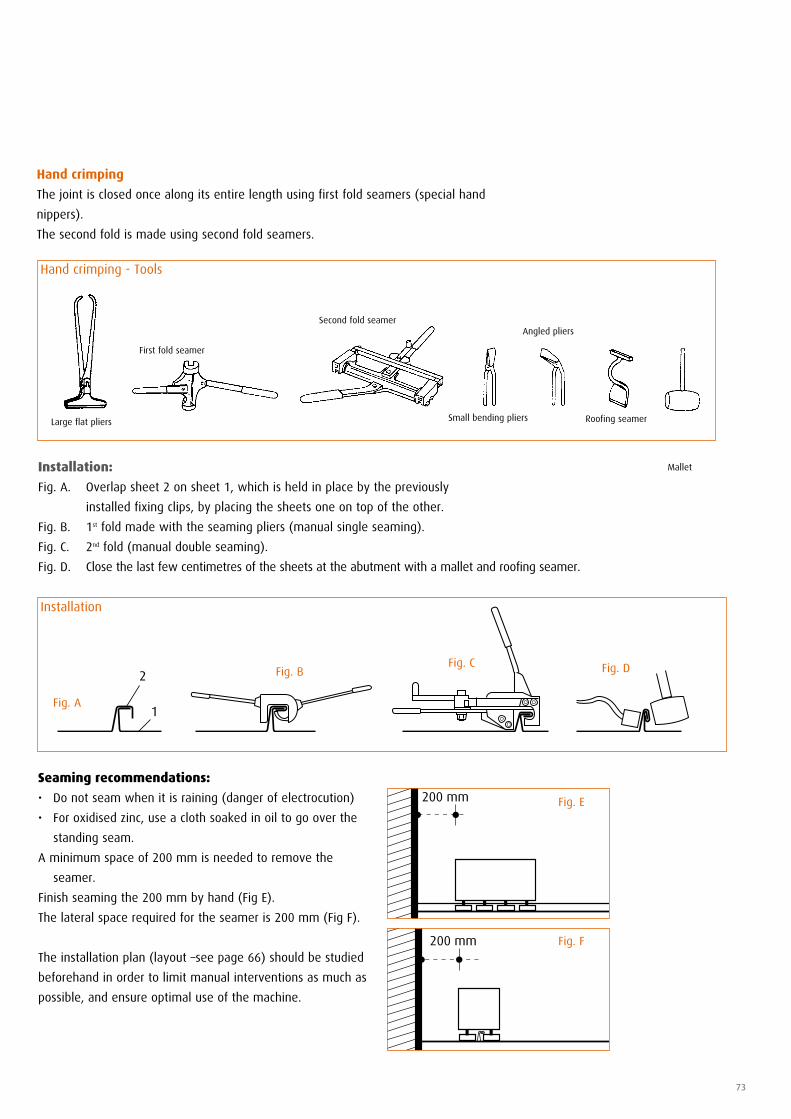
73
Large flat pliers
Hand crimping - Tools
Hand crimping
The joint is closed once along its entire length using first fold seamers (special hand
nippers).
The second fold is made using second fold seamers.
Second fold seamer
Small bending pliers
Angled pliers
Roofing seamer
Installation:
Fig. A. Overlap sheet 2 on sheet 1, which is held in place by the previously
installed fixing clips, by placing the sheets one on top of the other.
Fig. B. 1st fold made with the seaming pliers (manual single seaming).
Fig. C. 2nd fold (manual double seaming).
Fig. D. Close the last few centimetres of the sheets at the abutment with a mallet and roofing seamer.
2
1
Fig. C Fig. DFig. B
Installation
Fig. A
200 mm
200 mm
Seaming recommendations:
• Donotseamwhenitisraining(dangerofelectrocution)
• Foroxidisedzinc,useaclothsoakedinoiltogooverthe
standing seam.
A minimum space of 200 mm is needed to remove the
seamer.
Finish seaming the 200 mm by hand (Fig E).
The lateral space required for the seamer is 200 mm (Fig F).
The installation plan (layout –see page 66) should be studied
beforehand in order to limit manual interventions as much as
possible, and ensure optimal use of the machine.
Fig. E
Fig. F
First fold seamer
Mallet
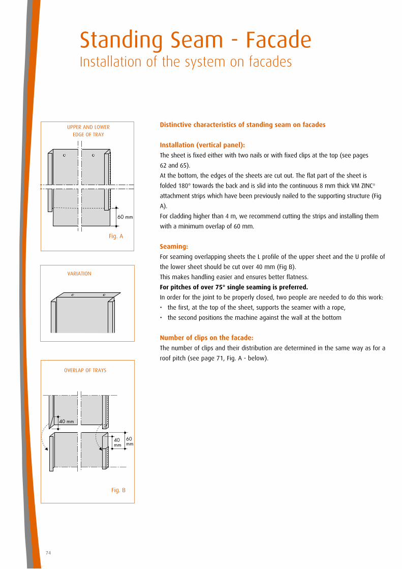
74
Distinctive characteristics of standing seam on facades
Installation (vertical panel):
The sheet is fixed either with two nails or with fixed clips at the top (see pages
62 and 65).
At the bottom, the edges of the sheets are cut out. The flat part of the sheet is
folded 180° towards the back and is slid into the continuous 8 mm thick VM ZINC®
attachment strips which have been previously nailed to the supporting structure (Fig
A).
For cladding higher than 4 m, we recommend cutting the strips and installing them
with a minimum overlap of 60 mm.
Seaming:
For seaming overlapping sheets the L profile of the upper sheet and the U profile of
the lower sheet should be cut over 40 mm (Fig B).
This makes handling easier and ensures better flatness.
For pitches of over 75° single seaming is preferred.
In order for the joint to be properly closed, two people are needed to do this work:
• thefirst,atthetopofthesheet,supportstheseamerwitharope,
• thesecondpositionsthemachineagainstthewallatthebottom
Number of clips on the facade:
The number of clips and their distribution are determined in the same way as for a
roof pitch (see page 71, Fig. A - below).
OVERLAP OF TRAYS
Fig. A
Fig. B
Standing Seam - FacadeInstallation of the system on facades
UPPER AND LOWER EDGE OF TRAY
VARIATION
As a general rule, the film must be removed from the entire surface at the same
time, immediately following the installation of VM ZINC®.
Exceptions to this rule:
• Roofs: when the roofer still has to walk on it to install flashings.
• Roofs: when people still have to walk on it to do other work such as masonry,
joint filling, rendering walls, installing windows, safety equipment, lighting
equipment, etc.
• Facades: when the cladding is close to the ground and there is still work to be
done around it, etc.
Under no circumstances must the film be left on installed VM ZINC® for more
than a month.
Pre-weathered QUARTZ-ZINC® and ANTHRA-ZINC® are produced using a surface
treatment on Natural VM ZINC®. As with all patinas, this change in the crystalline
structure of both surfaces of the metal evolves with time.
The pre-weathering treatment completed at the plant gradually evolves and
coalesces over time with the naturally formed zinc patina.
To ensure a consistent finish we recommend profiling and installing the
components of a new project using a parent coil.
Moving around on the VM ZINC® during and after installation on the roof
As a general rule, moving around on already installed VM ZINC®, is to be avoided
even if the latter is protected by film.
However, if it is necessary to walk on the zinc, we strongly advise moving around
using specially designed ladders and wearing safety shoes made for slippery surfaces
as Natural VM ZINC®, bilacquered VM ZINC® and pre-weathered VM ZINC® are slippery
whether they are covered by film or not, particularly when they are wet.
In any case, obey the building site safety standards in force and as a minimum
make sure you are always secured by a safety harness.
The VM ZINC® fitted should be protected during peripheral works (rough casting, tuck-
pointing, rendering, etc). However, this protection must allow effective ventilation of
the upper surface of the VM ZINC®.
Removing the protective film from pre-weathered zinc
75
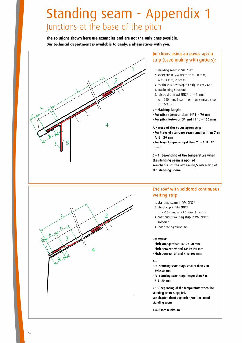
76
Standing seam - Appendix 1 Junctions at the base of the pitch
End roof with soldered continuous welting strip
1. standing seam in VM ZINC®
2. sheet clip in VM ZINC®
th = 0.8 mm, w = 80 mm, 2 per m
3. continuous welting strip in VM ZINC®,
soldered
4. loadbearing structure
Junctions using an eaves apron strip (used mainly with gutters):
1. standing seam in VM ZINC®
2. sheet clip in VM ZINC®, th = 0.8 mm,
w = 80 mm, 2 per m
3. continuous eaves apron strip in VM ZINC®
4. loadbearing structure
5. folded clip in VM ZINC®, th = 1 mm,
w = 250 mm, 2 per m or in galvanised steel,
th = 0.8 mm
L = Flashing length:
- For pitch stronger than 14° L = 70 mm
- For pitch between 3° and 14° L = 120 mm
A = nose of the eaves apron strip
- For trays of standing seam smaller than 7 m
A=B= 30 mm
- For trays longer or egal than 7 m A=B= 50
mm
C = C’ depending of the temperature when
the standing seam is applied
see chapter of the expansion/contraction of
the standing seam.
R = overlap
- Pitch stronger than 14° R=120 mm
- Pitch between 9° and 14° R=150 mm
- Pitch between 3° and 9° R=300 mm
A = B
- For standing seam trays smaller than 7 m
A=B=30 mm
- For standing seam trays longer than 7 m
A=B=50 mm
C = C’ depending of the temperature when the
standing seam is applied.
see chapter about expansion/contraction of
standing seam
A’=20 mm minimum
The solutions shown here are examples and are not the only ones possible.
Our technical department is available to analyse alternatives with you.
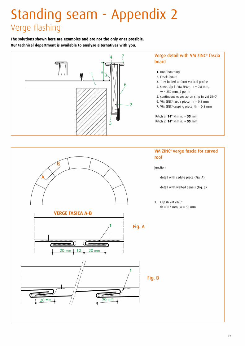
VERGE FASICA A-B
77
Standing seam - Appendix 2 Verge flashing
VM ZINC® verge fascia for curved roof
Junction:
detail with saddle piece (Fig. A)
detail with welted panels (Fig. B)
1. Clip in VM ZINC®
th = 0.7 mm, w = 50 mm
Verge detail with VM ZINC® fascia board
1. Roof boarding
2. Fascia board
3. Tray folded to form vertical profile
4. sheet clip in VM ZINC®, th = 0.8 mm,
w = 250 mm, 2 per m
5. continuous eaves apron strip in VM ZINC®
6. VM ZINC® fascia piece, th = 0.8 mm
7. VM ZINC® capping piece, th = 0.8 mm
Pitch ≥ 14° H min. = 35 mm
Pitch ≤ 14° H min. = 55 mm
The solutions shown here are examples and are not the only ones possible.
Our technical department is available to analyse alternatives with you.

78
Standing seam - Appendix 3 and 4 Flashings and forbidden contacts
Appendix 4: Forbidden Contacts
Direct contact with products such as fresh concrete, plaster, bitumen, mortar and
structures containing substances that are aggressive towards VM ZINC®.
Contact with metals such as copper, unprotected or ungalvanised iron, natural lead is
forbidden.
Only galvanised steel, natural lead protected by a patinating oil, FLEXUM® lacquered
lead, aluminium and austenitic stainless steel can come in contact with VM ZINC®.
Heating oil soot resulting from imperfect combustion landing on the zinc causes
irreparable damage. Regular maintenance of furnace burners and the use of fuel that
meets standards prevent this damage.
Using chimney “caps” may lead to aggressive deposits on the VM ZINC®.
Use of an uncovered finishing cone is therefore recommended for fuel oil heating
chimneys.
IMPORTANT: Box gutters, gutters, eaves apron strips, surrounds of windows set in
the roof and chimney surrounds must be installed before the panels are fixed.
Verge and ridge cap flashing is installed after the panels are fixed.
Appendix 3: Flashings
Arch. D. Wauters- QUARTZ-ZINC®>
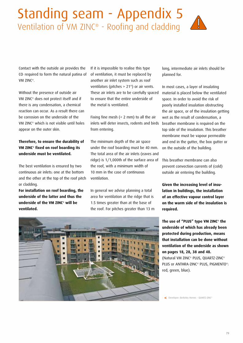
79
Standing seam - Appendix 5 Ventilation of VM ZINC® - Roofing and cladding
Contact with the outside air provides the
CO2 required to form the natural patina of
VM ZINC®.
Without the presence of outside air
VM ZINC® does not protect itself and if
there is any condensation, a chemical
reaction can occur. As a result there can
be corrosion on the underside of the
VM ZINC® which is not visible until holes
appear on the outer skin.
Therefore, to ensure the durability of
VM ZINC® fixed on roof boarding its
underside must be ventilated.
The best ventilation is ensured by two
continuous air inlets: one at the bottom
and the other at the top of the roof pitch
or cladding.
For installation on roof boarding, the
underside of the latter and thus the
underside of the VM ZINC® will be
ventilated.
If it is impossible to realise this type
of ventilation, it must be replaced by
another air inlet system such as roof
ventilators (pitches > 21°) or air vents.
These air inlets are to be carefully spaced
to ensure that the entire underside of
the metal is ventilated.
Fixing fine mesh (< 2 mm) to all the air
inlets will deter insects, rodents and birds
from entering.
The minimum depth of the air space
under the roof boarding must be 40 mm.
The total area of the air inlets (eaves and
ridge) is 1/1,000th of the surface area of
the roof, with a minimum width of
10 mm in the case of continuous
ventilation.
In general we advise planning a total
area for ventilation at the ridge that is
1.5 times greater than at the base of
the roof. For pitches greater than 13 m
long, intermediate air inlets should be
planned for.
In most cases, a layer of insulating
material is placed below the ventilated
space. In order to avoid the risk of
poorly installed insulation obstructing
the air space, or of the insulation getting
wet as the result of condensation, a
breather membrane is required on the
top side of the insulation. This breather
membrane must be vapour permeable
and end in the gutter, the box gutter or
on the outside of the building.
This breather membrane can also
prevent convection currents of (cold)
outside air entering the building.
Given the increasing level of insu-
lation in buildings, the installation
of an effective vapour control layer
on the warm side of the insulation is
required.
The use of “PLUS” type VM ZINC® the
underside of which has already been
protected during production, means
that installation can be done without
ventilation of the underside as shown
on pages 18, 28, 38 and 48.
(Natural VM ZINC® PLUS, QUARTZ-ZINC®
PLUS or ANTHRA-ZINC® PLUS, PIGMENTO®:
red, green, blue).
Developer: Berkeley Homes - QUARTZ-ZINC®>
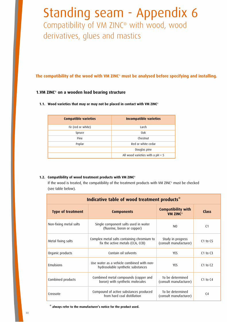
80
1. VM ZINC® on a wooden load bearing structure
1.1. Wood varieties that may or may not be placed in contact with VM ZINC®
Standing seam - Appendix 6Compatibility of VM ZINC® with wood, wood derivatives, glues and mastics
Compatible varieties Incompatible varieties
Fir (red or white) Larch
Spruce Oak
Pine Chestnut
Poplar Red or white cedar
Douglas pine
All wood varieties with a pH < 5
The compatibility of the wood with VM ZINC® must be analysed before specifying and installing.
1.2. Compatibility of wood treatment products with VM ZINC®
If the wood is treated, the compatibility of the treatment products with VM ZINC® must be checked
(see table below).
Indicative table of wood treatment products*
Type of treatment ComponentsCompatibility with
VM ZINC® Class
Non-fixing metal salts Single component salts used in water (fluorine, boron or copper)
NO C1
Metal fixing saltsComplex metal salts containing chromium to
fix the active metals (CCA, CCB)Study in progress
(consult manufacturer)C1 to C5
Organic products Contain oil solvents YES C1 to C3
EmulsionsUse water as a vehicle combined with non-
hydrosoluble synthetic substancesYES C1 to C2
Combined productsCombined metal compounds (copper and
boron) with synthetic moleculesTo be determined
(consult manufacturer)C1 to C4
CreosoteCompound of active substances produced
from hard coal distillationTo be determined
(consult manufacturer)C4
* always refer to the manufacturer’s notice for the product used.
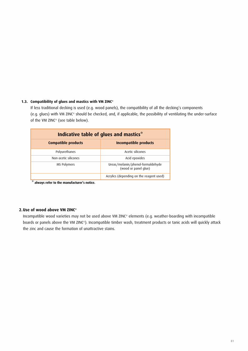
81
1.3. Compatibility of glues and mastics with VM ZINC®
If less traditional decking is used (e.g. wood panels), the compatibility of all the decking’s components
(e.g. glues) with VM ZINC® should be checked, and, if applicable, the possibility of ventilating the under-surface
of the VM ZINC® (see table below).
Indicative table of glues and mastics*
Compatible products Incompatible products
Polyurethanes Acetic silicones
Non-acetic silicones Acid epoxides
MS Polymers Ureas/melanin/phenol-formaldehyde (wood or panel glue)
Acrylics (depending on the reagent used)
2. Use of wood above VM ZINC®
Incompatible wood varieties may not be used above VM ZINC® elements (e.g. weather-boarding with incompatible
boards or panels above the VM ZINC®). Incompatible timber wash, treatment products or tanic acids will quickly attack
the zinc and cause the formation of unattractive stains.
* always refer to the manufacturer’s notice.
82
Subject
This document is intended for specifiers (building project architects and design teams)
and users (companies responsible for installation on the building site) of the designated product or system.
Its purpose is to provide the main information, text and diagrams, relating to specification and installation (including supporting structures) and flashing installation.
Any use or specification outside the area of use and/or specifications contained in this manual requires specific consultation with the Umicore technical departments. This does not commit the
latter to any responsibility with regard to the feasibility of the design or implementation of these projects.
Countries of application
This document applies exclusively to the specification and installation of the designated products or systems on building sites in United Kingdom and the Republic of Ireland.
Qualifications and reference documents
Please note that the correct use of this manual requires knowledge of VM ZINC® materials and of the zinc-roofing profession.
While construction is underway all standards in force must be respected, including:
• BritishStandardCodeofPracticeforcontrolofcondensationinbuildings,BS5250:2002.
• CalculationprocedureinBSENISO13788:2001.
• BS5250:2002:Codeofpracticeforcontrolofcondensationinbuildings.
• BS5427:Part1:1996:Codeofpracticefortheuseofprofiledsheetforroofandwallcladdingonbuildings.
• BS6229:1982:Flatroofswithcontinuouslysupportedcoverings.Codeofpractice.
• BS6399Part2:1997:Loadingforbuildings.Codeofpracticeforwindloads.
• BSEN501:Roofingproductsfrommetalsheet.Specificationsforfullysupportedroofingproductsofzincsheet.
• BSEN988:Zincandzincalloys.Specificationforrolledflatproductsforbuilding.
• BSEN12056:Part3:2000:Gravitydrainagesystemsinsidebuildings.Roofdrainage,layoutandcalculation.
• BSENISO13788:Hygrothermalperformanceofbuildingcomponentsandbuildingelements.Internalsurfacetemperaturetoavoidcriticalsurfacehumidityandinterstitialcondensation.
Calculation methods.
• CP143:Part5:1964Zinc:Codeofpracticeforsheetroofandwallcoverings.Zinc.
Furthermore, Umicore offers training courses specifically for professionals.
Responsibility
The specification and installation of VM ZINC® products manufactured by Umicore are the sole responsibility of the architects and building professionals who must ensure these products are used in
a way suited to the end purpose of the construction and that they are compatible with other products and techniques used.
The specification and installation of the products implies respecting the standards in force and the manufacturer’s recommendations. In this regard, Umicore publishes and regularly updates
specification and installation manuals for specific geographic areas and provides training courses. All the information on the latter can be obtained from the local VM ZINC team.
Unless otherwise agreed in writing, Umicore cannot be held responsible for any damages resulting from a specification or installation that does not respect all of Umicore’s specifications and the
above standards and practices.
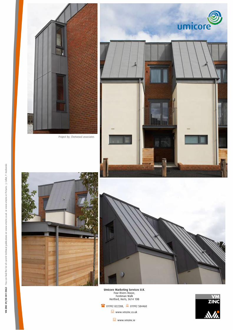
Umicore Marketing Services U.K. Four Rivers House,
Fentiman Walk Hertford, Herts, SG14 1DB
( 01992 822288, 01992 584460
: www.vmzinc.co.uk
: www.vmzinc.ie
VMB
000
04 -
F04
060
4 VM
ZIN
C 09
/08
001
EN
G3
- Yo
u ca
n fin
d th
e lis
t of
cur
rent
tec
hnic
al p
ublic
atio
ns o
n w
ww
.vm
zinc
.co.
uk. o
r w
ww
.vm
zinc
.ie P
ictu
res:
J.
Collo
t, P.
Koz
low
ski.
Project by: Chetwood associates


![CICADA - USENIX · 1 vm 2 vm 3 vm 4 vm 5vm 6 vm 7 vm 8 vm 9 vm 2 vm 3 vm 4 vm 5 vm 6 vm 7 vm 8 vm 9 vm 1 rigid application (similar to VOC [1]) vm 1 vm 2 vm 3 vm 4 vm 5vm 6 vm 7 vm](https://img.pdfslide.us/doc/110x75/5f3ade2be7477529602b0cb3/cicada-usenix-1-vm-2-vm-3-vm-4-vm-5vm-6-vm-7-vm-8-vm-9-vm-2-vm-3-vm-4-vm-5-vm.jpg)