Embed Size (px)
Citation preview
VLBA Correlator Memo No.-ll (860709)
VLBA CORRELATOR HARDWARE TOPICS Ray Escoffier July 9, 1986
I) Introduction
This memo will describe the present state of the design of the VLBA correlator. The thoughts given here represent an evolution in the design of the correlator on a path to a final specification and design. In this light, information in this memo is to be considered somewhat preliminary in nature, being the next step up from VLBA Correlator memo 62.
Some of the discussions given here are responses to new concepts that have surfaced since the last spate of VLBA correlator memos, such as zero padded Fourier transforms.
One change in the VLBA correlator design from that described in correlator memo 62 that should be pointed out at the onset is the intention to use only a single length of FFT. The memo 62 design tried to optimize the station electronics and do long Fourier transforms when only a small number of IF channels per antenna were active and do shorter transforms when more channels per antenna were active. In this memo it will be assumed that the FFT length and the number of active channels per antenna are independent. Designs and specifications for FFT lengths of 1024, 2048, and 4096 points will be presented.
II) Correlator options
This section will try to give the observation options presently planned for the VLBA correlator and to show how these options interact in operation. Three equations are presented from which important operational specifications for the VLBA correlator may be derived. Parameters used in these equations include;
1) A, antenna parameter
2) C, channel parameter
3) D, sample dispersal
,«l/2 for 10 antenna operation ,B1 for 20 antenna operation
2, 4, or 8 for 1, 2, 4, or 8 IF channels per antenna
,=1 normal ,=2 if channel is oversampled and the observer wants to perform independent Fourier transforms on interleaved sets of samples (for example on odd and even samples if the oversample factor is 2).
4) E, to observe multiple phase centers
5) F, polarization parameter
6) S, sample factor (S=S1 X S2)
7) SI, fraction of S alloted to station electronics
,=1, 2, 4, or 8 for 1, 2, 4, or 8 phase centers per IF channel
,S1 for no polarization cross products ,=2 when polarization cross products desired
,=1 for Nyquist sampling ,=1/2 for twice Nyquist sampling ,=1/4 for four times Nyquist sampling ,=1/8 for eight times Nyquist sampling
,=1, 1/2, 1/4, 1/8
8) S2, fraction of S alloted to baseline electronics
9) V, FFT overlap parameter
10) Z, zero padding parameter
,=1, 1/2, 1/4, 1/8
,=1 for contiguous Fourier transforms ,=2 for overlapping Fourier transforms
,=1 for non-padded Fourier transforms ,=2 for zero padded Fourier transforms
The equations below establish the operational capability of the presently envisioned VLBA correlator. To best understand these equations, one should keep in mind a little of the system block diagram. The station electronics will include enough logic to perform 160 simultaneous fast Fourier transforms on the playback data (8 per antenna for 20 stations) and the baseline logic will include 8 20-by-20 triangular arrays of cross-multipliers. If the number of channels per antenna is small, the transformed output of these channels may be spread out among the multiplier arrays and the accumulator made simpler by requiring fewer accesses to RAM per unit time. If there are many channels per antenna active, spectral points at the FFT output cannot all be preserved after cross-multiplication and some number of adjacent points must be summed together before accumulation to accomplish the same simplification above. Equation 1, below, fits all of the possible Fourier transforms into the 160 available FFT logic circuits, and equation 2 fits the possible spectral resolution into the accumulator.
M = C'D'E*V'Z (1)
Equation Cl) defines H which is the number of independent Fourier transforms that will be performed per antenna. Allowable values of M in the design described here depend on the sample factor SI since the hardware log^c that will do the transforms can do a certain number of transforms per unit time. If A has a value of 1, H.S1 can only have values of 1, 2, 4, or 8. If A is 1/2, M*S1 may also take on a value of 16.
2
NB = F*S2*C*E / 2-Sl'M-A (F = 2048 or 4096) (2) NB = F* S2'C*E / Sl'H'A (F = 1024) (2A)
Equation (2) defines NB which is the number of spectral points obtained from a given experiment per baseline in terms of the Fourier transform length, F. Two forms of this equation (2 and 2A) are given. The reason for the two forms is an attempt to preserve the resolution specification given in VLBA correlator memo 62 of 1024 spectral points for line observations. The intent is, if a transform length of 1024 is adopted for the VLBA correlator, to provide 1024 spectral points over 2 channels (512 points each). If an FFT length of 2048 or 4096 points is adopted for the correlator design all of the good spectral points (1024 or 2048 respectively) will be kept as a final processor output for one channel operation. When two or more channels per antenna are active, however, the accumulator will no longer be able to keep all spectral points delivered at the cross-multiplier output. In order to fit into a practical accumulator some number of adjacent points will be summed together before accumulation. If an FFT of 1024 points were selected for the correlator, however, spectral line performance would suffer since one channel operation would result in spectral resolution of 512 points per baseline. Equation (2A) is an attempt to make a 1024 point FFT more acceptable by promising an accumulator that will preserve all of the cross-points for 2 as well as 1 channel operation. Actually, for an FFT size of 1024 and one channel operation equation (2) should be used instead of equation (2A). The number of spectral points per channel per baseline is tabulated for the three proposed FFT lengths in tables I, II, and III.
K = F / 2*N (3)
Equation (3) defines K, the number of adjacent FFT spectral points that must be summed together after cross-multiplying in order to fit into the accumulator. K is given in terms of N, the number of spectral points obtained per channel (given by NB/C*E*P in most cases).
It may seea as if the list above contains many parameters and that the VLBA correlator will be excessively complicated in order to provide so many options. However, equation (1) illustrates the underlying simplicity in providing all these options in that many options are functionally the same thing. In other words the apparent complexity reduces to a simple question of how the FFT logic circuits are initially loaded with data (the complexity of the software to support many operating modes is, of course, another matter).
3
Ill) PERFORMANCE
This section presents three tables of correlator performance for three hardware FFT lengths. The reason for giving three options is to help to illustrate the hardware/performance trade-offs. Section IV will discuss hardware considerations that pertain to the FFT length.
Table I gives the VLBA correlator performance if 1024 point Fourier transforms are done, table II gives the performance for 2048 point transforms, and table III is for 4096 point transforms. Column N gives the number of spectral points per channel per baseline an observation will produce and NB gives the number of spectral points per baseline.
IV) HARDWARE
This section will discuss the numerical standard tentatively selected for the mathematics of the FFT and cross~multipliers and other topics of the VLBA correlator design.
The numerical standard being considered for the FFT logic is a 9-bit floating point system with a 5-bit 2's complement mantissa and a 4-bit positive integer exponent. The hardware design of the last month or so seems to indicate that a floating point notation would be the most inexpensive method of satisfying both the resolution and dynamic range requirements of the station based FFT logic. Since all of the numbers represented through the FFT, the fractional sample time correction, and the baseline multipliers (see next paragraph) are complex, the floating point structure was simplified to a 5-bit mantissa for real components, a 5-bit mantissa for imaginary components, and a common 4-bit exponent (Marty Ewing's idea). Later reference to this number format will call it 5,5,4 floating point.
The present design concept is to implement the FFT butterfly logic in a single custom gate array chip. Modern gate array technology seem to be able fit the four (5-bit by 5-bit) multipliers, adder stages, and the floating point to fixed point and fixed point to floating point conversion logic required by a butterfly onto a single medium size chip with ease. This butterfly chip will reduce the FFT logic to a simple structure of RAM chips and butterfly chips reducing the overall system chip count delightfully. In addition, since the butterfly chip must have the complex multiply function required by an FFT butterfly, this complex multiplier may by used other places in the system. For example the fractional sample time error correction logic and the baseline multipliers both require complex multipliers for which the butterfly chip can be made usable. A small amount of additional logic can be put into the gate array to further reduce the system chip count. For instance the butterfly adder stages may be modified somewhat to also serve as the accumulator adder. Figure 1 illustrates the intended multi-use functionality of the gate array.
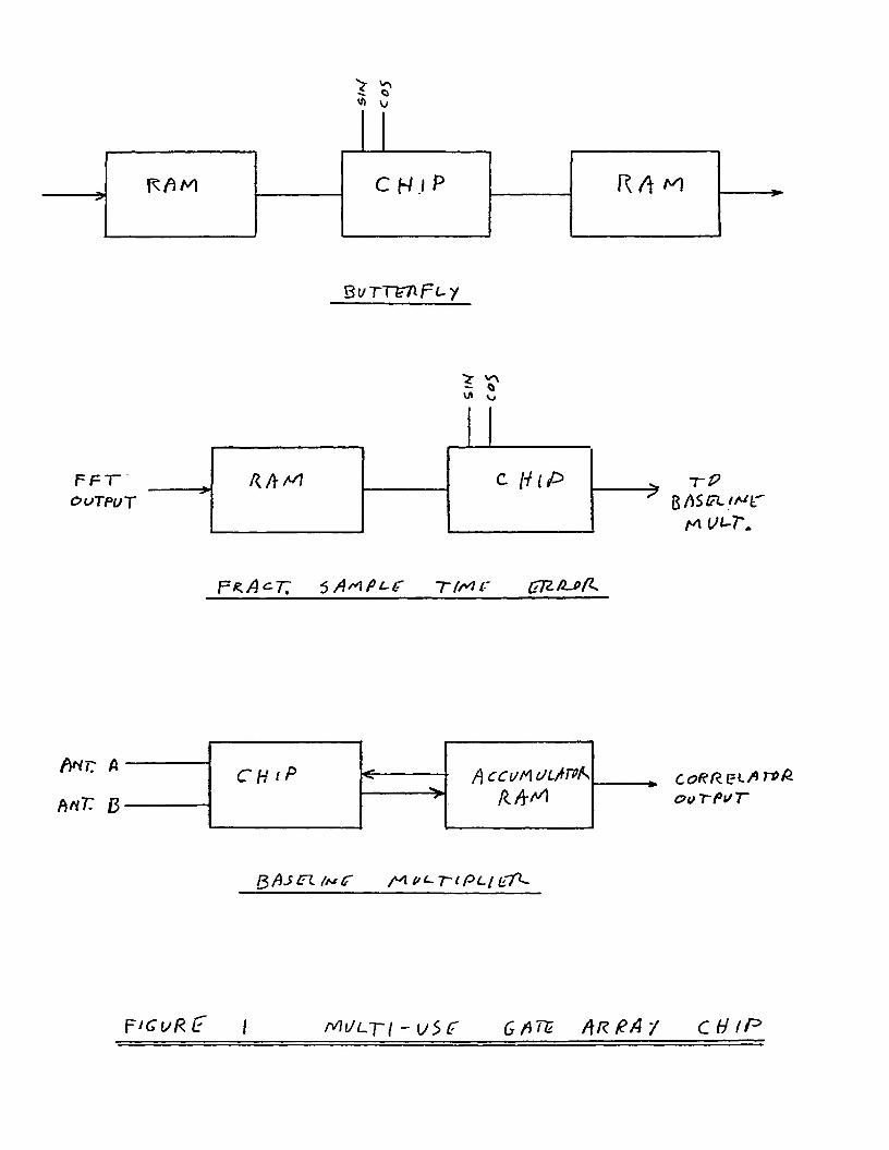
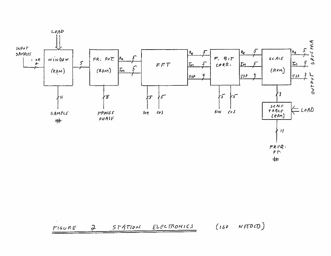
Figure 2 gives a block diagram of part of the station electronics data path. The functions include a programmable window function circuit, the fringe
4
rotator, the FFT logic, the fractional sample time correction, and an output data scaling circuit. Signal quantization levels along the data path are also shown. All quantization levels past the fringe rotator are in 5,5,4 bit floating point although the fringe rotator outputs and the sin/cos terms all have zero exponent and hence their exponents are not shown. The scaling stage will subtract a programmable number (programmable by antenna, channel, and spectral point number) from each spectral points' exponent to reduce the dynamic range that the baseline cross-multiplier must contend with. The numbers subtracted are known to the computer system and will be used to later correct the final results. The result will be exact 5,5,4 arithmetic completely thru the system (actually, the arithmetic will not be exact in that peak clipping and small value truncation will occasionally take place in the scaling stage).
More dynamic range, for instance at the fringe rotator output, can be accommodated if it is necessary by allowing small non-zero exponents at the FFT input (with a value of less than 4 if a 4096 point FFT is used since more would allow exceeding the 4-bit exponent range at the FFT output).
The exact FFT length will depend on the performance-cost tradeoffs. The hardware cost considerations in the FFT length, F, include;
1) increase in FFT butterfly cost with increasing F (log F variation) 2) additional accumulator storage cost (linear with F) 3) additional cost due to increasing size of the RAMs (linear with F)
While a 2048 point FFT may be sufficient from a performance standpoint, some consideration has been given to doing 4096 point transforms primarily because this length will allow the use of a radix 4 butterfly FFT. A radix 4 butterfly chip might cut the butterfly chip count by half over the number of butterfly chips required by a radix 2 implementation (it depends on whether or not a radix 4 butterfly chip can be made that can do a 5-bit by 5-bit multiply in 31.25 nsec). In any case a radix 4 butterfly will always cut the RAM chip requirement by half. The 1024 FFT length is the best of all worlds except that it falls short in performance.
V) OTHER TOPICS BEING CONSIDERED
Two additional topics now being considered but that are not far enough along to be presented in detail here deserve comment. First Jon Romney and Barry Clark think that while 5-bit quantization will surffice for the samples, the sin/cos terms will be used over and over again and hence might need more bits to reduce systematic errors in the FFT to acceptable levels. At the present time Barry thinks that a 5-bit by 6-bit butterfly multiply will be needed. This change requires only a minor hardware increase to accommodate.
Second, several people are uneasy about the concept of summing adjacent spectral points after cross-multiplication and before accumulation. Some thought is being given to making an accumulator that can hold all of the cross-spectral points produced. To make this practical, it would be necessary to return to doing Fourier transforms with transform lengths that vary with the number of active channels per antenna.
5
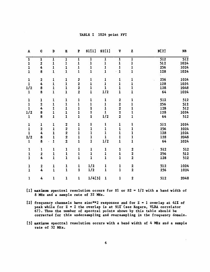
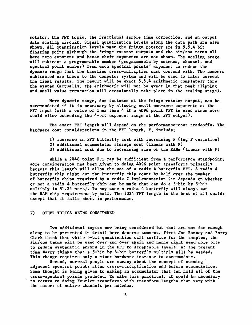
TABLE I 1024 point FFT
A c D E P Sl[l] S2[l] V Z N[2] NB
1 1 1 1 1 1 1 1 512 512 2 1 1 1 1 1 1 1 512 1024 4 1 1 1 1 1 1 1 256 1024 8 1 1 1 1 1 1 128 1024
2 1 1 2 1 1 1 1 256 1024 4 1 1 2 1 1 1 1 128 1024 8 1 1 2 1 1 1 1 128 2048 8 1 1 2 1 1/2 1 1 64 1024
1 1 1 1 1 1 2 1 512 512 2 1 1 1 1 1 2 1 256 512 4 1 1 1 1 1 2 1 128 512 8 1 1 1 1 1 2 1 128 1024 8 1 1 1 1 1/2 2 1 64 512
1 1 2 1 1 1 1 1 512 1024 2 1 2 1 1 1 1 1 256 1024 4 1 2 1 1 1 1 1 128 1024 8 1 2 1 1 1 1 1 128 2048 8 1 2 1 1 1/2 1 1 64 1024
1 1 1 1 1 1 1 2 512 512 2 1 1 1 1 1 1 2 256 512 4 1 1 1 1 1 1 2 128 512
2 1 1 1 1/2 1 1 2 512 1024 4 1 1 1 1/2 1 1 2 256 1024
4 1 1 1 l/4[3] 1 1 2 512 2048
[1] maximum spectral reso 8 MHz and a sample ra
ution occurs for SI or S2 e of 32 MHz.
1/2 with a band width of
[2] frequency channels have sinc**2 responses and for Z = 1 overlap at 41% of peak while for Z = 2 the overlap is at 91% (see Rogers, VLBA correlator 67). Thus the number of spectral points shown by this table should be corrected for this undersampling and oversampling in the frequency domain.
[3] maximum spectral resolution occurs with a band width of 4 MHz and a sample rate of 32 MHz.
6
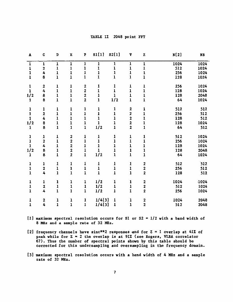
TABLE II 2048 point FFT
A C D E P Sl[l] S2[l] V Z N[2] NB
1 1 1 1 1 1 1 1 2 1 1 1 1 1 1 4 1 1 1 1 1 1 8 1 1 1 1 1
1 2 1 1 2 1 1 1 4 1 1 2 1 1
1 / 2 8 1 1 2 1 1 1 8 1 1 2 1 1 / 2
1 1 1 1 1 1 1 1 2 1 1 1 1 1 1 4 1 1 1 1 1
1 / 2 8 1 1 1 1 1 1 8 1 1 1 1 / 2 1
1 1 1 2 1 1 1 1 2 1 2 1 1 1 1 4 1 2 1 1 1
1 / 2 8 1 2 1 1 1 1 8 1 2 1 1 / 2 1
1 1 1 1 1 1 1 1 2 1 1 1 1 1 1 4 1 1 1 1 1
1 1 1 1 1 1 / 2 1 1 2 1 1 1 1 / 2 1 1 4 1 1 1 1 / 2 1
1 2 1 1 1 l/4[3] 1 1 4 1 1 1 l/4[3] 1
1 1 1024 1024 1 1 512 1024 1 1 256 1024 1 1 128 1024
1 1 256 1024 1 1 128 1024 1 1 128 2048 1 1 64 1024
2 1 512 512 2 1 256 512 2 1 128 512 2 1 128 1024 2 1 64 512
1 1 512 1024 1 1 256 1024 1 1 128 1024 1 1 128 2048 1 1 64 1024
1 2 512 512 1 2 256 512 1 2 128 512
1 2 1024 1024 1 2 512 1024 1 2 256 1024
1 2 1024 2048 1 2 512 2048
[1] maximum spectral resolution occurs for SI or S2 = 1/2 with a band width of 8 MHz and a sample rate of 32 MHz.
[2] frequency channels have sinc**2 responses «nd for Z = 1 overlap at 41% of peak while for Z = 2 the overlap is at 91% (see Rogers, VLBA correlator 67). Thus the number of spectral points shown by this table should be corrected for this under sampling and over sampling in the frequency domain.
[3] maximum spectral resolution occurs with a band width of 4 MHz and a sample rate of 32 MHz.
7

TABLE III 4096 point FFT
A c D E P Sill] S2[l] V Z N[2] NB
1 1 1 1 1 1 1 2048 2048 2 1 1 1 1 1 1 1024 2048 4 1 1 1 1 1 1 512 2048 8 1 1 1 1 1 1 256 2048
2 1 1 2 1 1 1 512 2048 4 1 1 2 1 1 1 256 2048 8 1 1 2 1 1 1 256 4096 8 1 1 2 1 1 2 1 1 128 2048
1 1 1 1 2 1 1024 1024 2 1 1 1 2 1 512 1024 4 1 1 1 2 1 256 1024 8 1 1 1 2 1 256 2048 8 1 1 1/2 2 1 128 1024
1 1 2 1 1 1 1024 2048 2 1 2 1 1 1 512 2048 4 1 2 1 1 1 256 2048 8 1 2 1 1 1 256 4096 8 1 2 1/2 1 1 128 2048
1 1 1 1 1 2 1024 1024 2 1 1 1 1 2 512 1024 4 1 1 1 1 2 256 1024
1 1 1 1/2 1 2 2048 2048 2 1 1 1/2 1 2 1024 2048 4 1 1 1/2 1 2 512 2048
2 1 1 l/4[3] 1 2 2048 4096 4 1 1 l/4[3] 1 2' 1024 4096
maximum spectral resol ution occurs for SI or S2 = 1/2 with a band width of 8 MHz and a sample ra e of 32 MHz.
[2] frequency channels have sinc**2 responses *nd for Z • 1 overlap at 41% of peak while for Z = 2 the overlap is at 91% (see Rogers, VLBA correlator 67). Thus the number of spectral points shown by this table should be corrected for this undersampling and oversampling in the frequency domain.
[3] maximum spectral resolution occurs with a band width of 4 MHz and a sample rate of 32 MHz.
8
> ^ £ Ci
Qi/rv^nFL- y
FFT OUTPUT
TP
Mr. A
MT. B CH iP A ccvr\ ULftrok *» CH iP < A ccvr\ ULftrok *» CH iP A ccvr\ ULftrok
ovTfii/T
QftJlFl ihctr et-TtPL/
F iGvRf I Mi/LTi-v$<r GflTt ARRAY cutf*
lupvr i>MPurs
LOfiP
FFT
'S .
SitY C*S
**
GK/>
r JT •y—
X
f, 8 / r
'J
S\N C*S
s<iMC •y-X 5" \A -f—
>
Tfitfinr
/ ' / /
LrM ? ^ — 1 — f - *
Q.
o
FR •
pr.
F i & u K t 5L 5 kLF<- T A p N (CJ ( u o N f C O C O ' )