Embed Size (px)
Citation preview
7/29/2019 VLAN Introduction
http://slidepdf.com/reader/full/vlan-introduction 1/21
VLAN Introduction
―A virtual LAN (VLAN) is a group of networking devices in the same broadcast domain‖
It is the concept of VLAN that most of the books are using but it doesn’t help us understand the
benefits of VLANs. If you ask ―What is a LAN?‖ you will receive the same answer: it is also a group of
networking devices in the same broadcast domain!
To make it clearer, I expanded the above statement into a bit longer statement :)
―A virtual LAN (VLAN) is a group of networking devices in the same broadcast domain, logically‖
It means that the devices in the same VLAN may be widely separated in the network, both by
geography and location. VLANs logically segment the network into different broadcast domains so that
packets are only switched between ports that are designated for the same VLAN.
Let’s take an example to understand the benefits of VLAN. Suppose you are working in a big company
with many departments, some of them are SALES and TECHNICAL departments. You are tasked to
separate these departments so that each of them can only access specific resources in the company.
This task is really easy, you think. To complete this task, you just need to use different networks for
these departments and use access-list to allow/deny that network to a specific resource. For example,
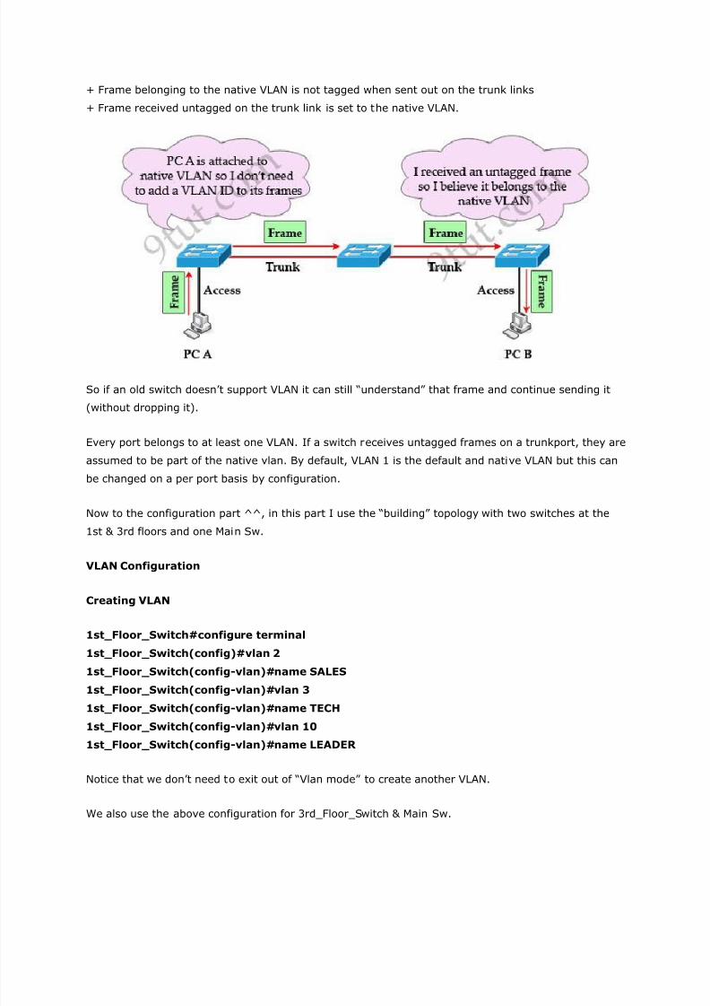
you assign network 192.168.1.0/24 for SALES and 192.168.2.0/24 for TECH. At the ―Company router‖
you apply an access-list to filter traffic from these networks. Below is the topology of your network
without VLANs:
Everything looks good and you implement this design to your company. But after one month you
receive many complaints from both your colleagues and leaders.
+ First, your department leaders need to access to additional private resources which employees are
not allowed.
7/29/2019 VLAN Introduction
http://slidepdf.com/reader/full/vlan-introduction 2/21
+ Second, the company has just recruited some new SALES employees but now the SALES room is
full so they have to sit at the 1st floor (in the TECH area). They want to access to SALES resources but
they can only access to the TECH resources because they are connecting to TECH switch.
To solve the first problem maybe you will create a new and more powerful network for your leaders.
But notice that each leader sits at different floor so you will need to link all of them to a switch ->
what a mess!
The second problem is more difficult than the first one. Maybe you have to create another network at
the TECH area and apply the same policy as the SALES department for these hosts -> another mess in
management!
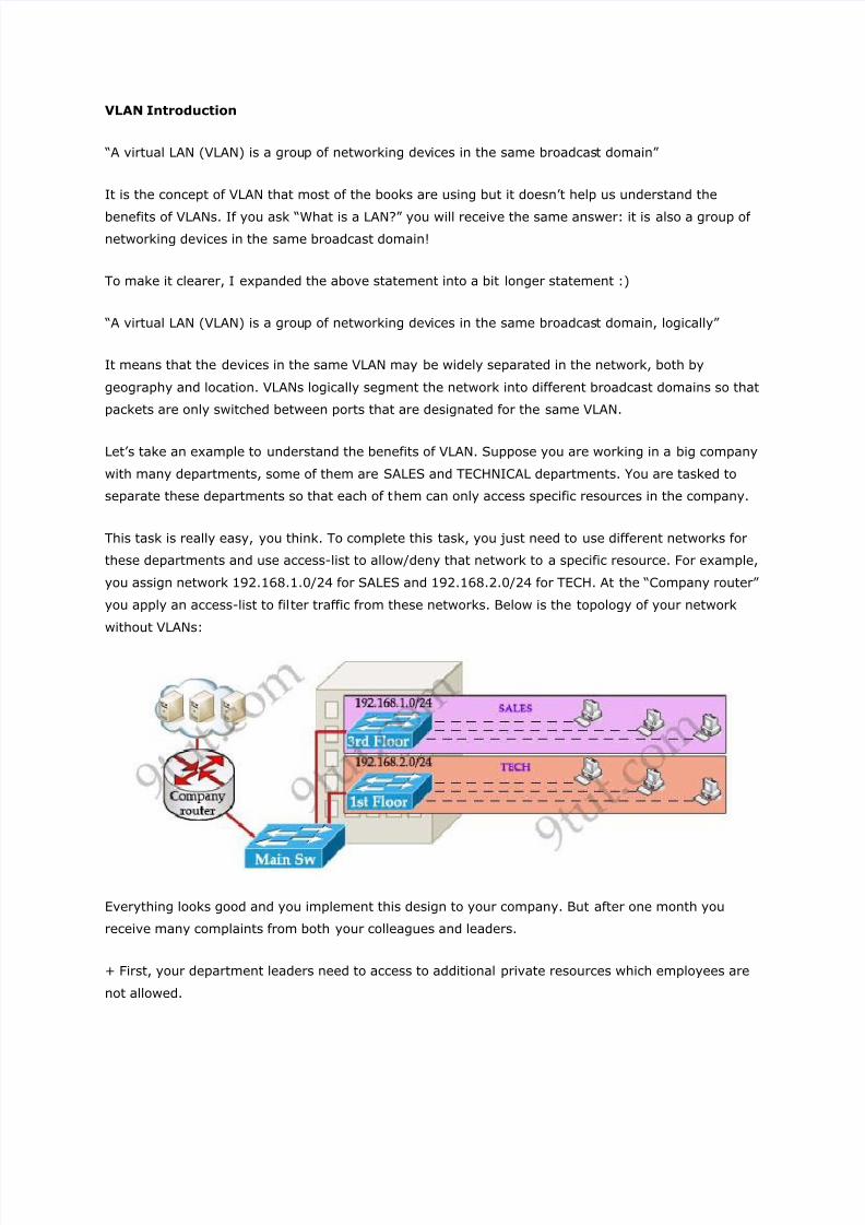
Maybe you will be glad to know VLAN can solve all these problems. VLAN helps you group users
together according to their function rather than their physical location. This means you can use the
same network for hosts in different floors (of course they can communicate with each other).
In this design:
+ You can logically create a new network with additional permissions for your leaders (LEADER
network) by adding another VLAN.
+ Employees can sit anywhere to access the resources in their departments, provided that you allow
them to do so.
+ Computers in the same department can communicate with each other although they are at different
floors.
If these departments expand in the future you can still use the same network in any other floor. For
example, SALES needs to have 40 more employees -> you can use 4th floor for this expansion
without changing the current network.
7/29/2019 VLAN Introduction
http://slidepdf.com/reader/full/vlan-introduction 3/21
But wait… maybe you recognize something strange in the above design? How can 2 computers
connecting to 2 different switches communicate? If one computer sends a broadcast packet will it be
flooded to other departments as switch doesn’t break up broadcast domains?
The answer is ―Yes, they can!‖ and it is the beauty of VLAN. Hosts in the same VLAN can communicate
normally even they are connecting to 2 or more different switches. This makes the management much
more simple.
Although layer 2 switches can only break up collision domains but VLANs can be used to break up
broadcast domains. So if a computer in SALES broadcasts, only computers in SALES will receive that
frame.
So we don’t need a router, right? The answer is ―we still need a router‖ to enable different VLANs to
communicate with each other. Without a router, the computers within each VLAN can communicate
with each other but not with any other computers in another VLAN. For example, we need a router to
transfer file from LEADER to TECH. This is called ―interVLAN routing‖.
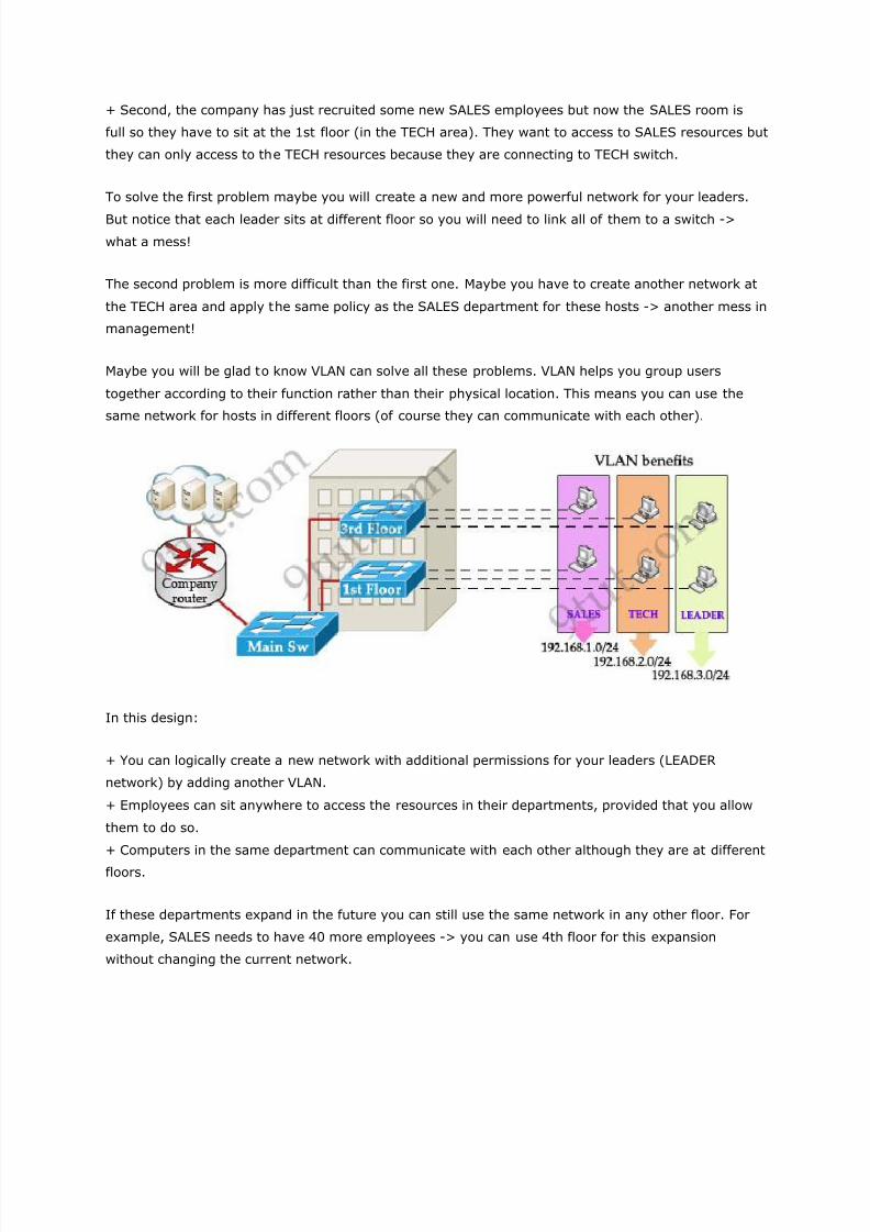
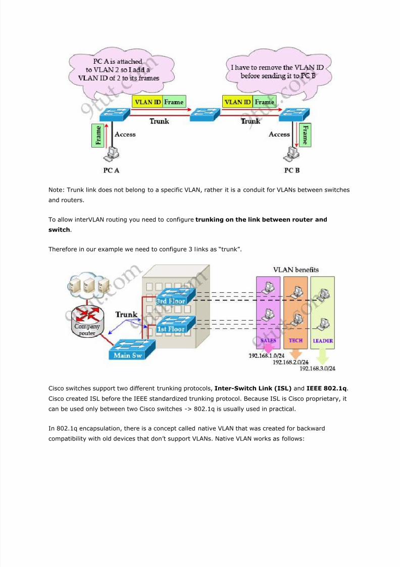
When using VLANs in networks that have multiple interconnected switches, you need to use VLAN
trunking between the switches. With VLAN trunking, the switches tag each frame sent between
switches so that the receiving switch knows which VLAN the frame belongs to. This tag is known as a
VLAN ID. A VLAN ID is a number which is used to identify a VLAN.
Notice that the tag is only added and removed by the switches when frames are sent out on the trunk
links. Hosts don’t know about this tag because it is added on the first switch and removed on the last
switch. The picture below describes the process of a frame sent from PC A to PC B.
7/29/2019 VLAN Introduction
http://slidepdf.com/reader/full/vlan-introduction 4/21
Note: Trunk link does not belong to a specific VLAN, rather it is a conduit for VLANs between switches
and routers.
To allow interVLAN routing you need to configure trunking on the link between router and
switch.
Therefore in our example we need to configure 3 links as ―trunk‖.
Cisco switches support two different trunking protocols, Inter-Switch Link (ISL) and IEEE 802.1q.
Cisco created ISL before the IEEE standardized trunking protocol. Because ISL is Cisco proprietary, it
can be used only between two Cisco switches -> 802.1q is usually used in practical.
In 802.1q encapsulation, there is a concept called native VLAN that was created for backward
compatibility with old devices that don’t support VLANs. Native VLAN works as follows:
7/29/2019 VLAN Introduction
http://slidepdf.com/reader/full/vlan-introduction 5/21
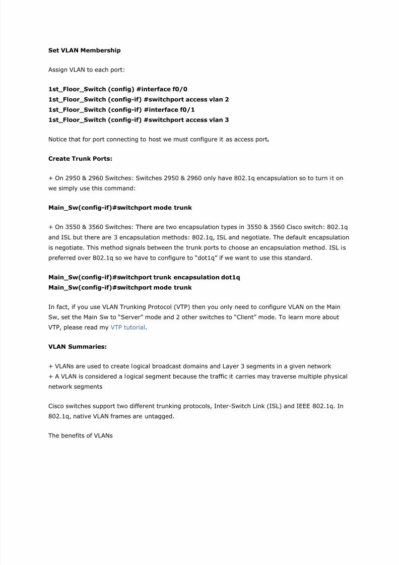
+ Frame belonging to the native VLAN is not tagged when sent out on the trunk links
+ Frame received untagged on the trunk link is set to the native VLAN.
So if an old switch doesn’t support VLAN it can still ―understand‖ that frame and continue sending it
(without dropping it).
Every port belongs to at least one VLAN. If a switch receives untagged frames on a trunkport, they are
assumed to be part of the native vlan. By default, VLAN 1 is the default and native VLAN but this can
be changed on a per port basis by configuration.
Now to the configuration part ^^, in this part I use the ―building‖ topology with two switches at the
1st & 3rd floors and one Main Sw.
VLAN Configuration
Creating VLAN
1st_Floor_Switch#configure terminal
1st_Floor_Switch(config)#vlan 2
1st_Floor_Switch(config-vlan)#name SALES
1st_Floor_Switch(config-vlan)#vlan 3
1st_Floor_Switch(config-vlan)#name TECH
1st_Floor_Switch(config-vlan)#vlan 10
1st_Floor_Switch(config-vlan)#name LEADER
Notice that we don’t need to exit out of ―Vlan mode‖ to create another VLAN.
We also use the above configuration for 3rd_Floor_Switch & Main Sw.
7/29/2019 VLAN Introduction
http://slidepdf.com/reader/full/vlan-introduction 6/21
Set VLAN Membership
Assign VLAN to each port:
1st_Floor_Switch (config) #interface f0/0
1st_Floor_Switch (config-if) #switchport access vlan 2
1st_Floor_Switch (config-if) #interface f0/1
1st_Floor_Switch (config-if) #switchport access vlan 3
Notice that for port connecting to host we must configure it as access port.
Create Trunk Ports:
+ On 2950 & 2960 Switches: Switches 2950 & 2960 only have 802.1q encapsulation so to turn it on
we simply use this command:
Main_Sw(config-if)#switchport mode trunk
+ On 3550 & 3560 Switches: There are two encapsulation types in 3550 & 3560 Cisco switch: 802.1q
and ISL but there are 3 encapsulation methods: 802.1q, ISL and negotiate. The default encapsulation
is negotiate. This method signals between the trunk ports to choose an encapsulation method. ISL is
preferred over 802.1q so we have to configure to ―dot1q‖ if we want to use this standard.
Main_Sw(config-if)#switchport trunk encapsulation dot1q
Main_Sw(config-if)#switchport mode trunk
In fact, if you use VLAN Trunking Protocol (VTP) then you only need to configure VLAN on the Main
Sw, set the Main Sw to ―Server‖ mode and 2 other switches to ―Client‖ mode. To learn more about
VTP, please read my VTP tutorial.
VLAN Summaries:
+ VLANs are used to create logical broadcast domains and Layer 3 segments in a given network
+ A VLAN is considered a logical segment because the traffic it carries may traverse multiple physical
network segments
Cisco switches support two different trunking protocols, Inter-Switch Link (ISL) and IEEE 802.1q. In
802.1q, native VLAN frames are untagged.
The benefits of VLANs
7/29/2019 VLAN Introduction
http://slidepdf.com/reader/full/vlan-introduction 7/21
1. Segment networks into multiple smaller broadcast domains without Layer 3 network devices such
as routers. VLANs make switched Ethernet networks more bandwidth-efficient through this
segmentation of broadcast domains.
2. Group users together according to function rather than physical location. In a traditional network,
users in a given work area are on the same network segment regardless of their job description or
department. Using VLANs, however, you could have one salesperson in each work area of the building
sitting next to engineers in their work area, yet on a separate logical network segment.
3. The ability to reconfigure ports logically without the need to unplug wires and move them around. If
a user takes his or her computer to a new work area, no cables need to be swapped on the switch,
just access the switch and issue commands to change the VLAN assignments for the old and new
ports. VLANs thus simplify the process of adding, moving, and deleting users on the network. They
also improve network security by avoiding cabling mishaps that can arise when users are moved in
traditional Ethernet networks.
InterVLAN Routing Tutorial
What is InterVLAN routing?
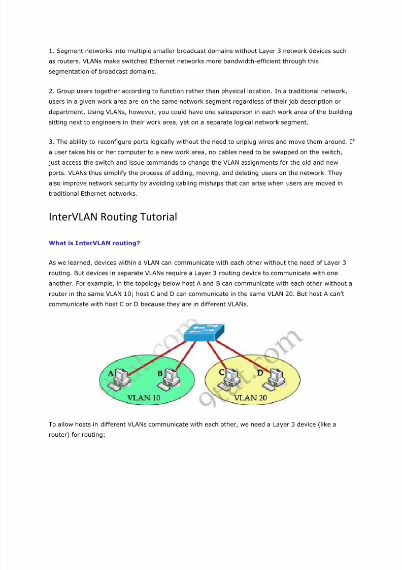
As we learned, devices within a VLAN can communicate with each other without the need of Layer 3
routing. But devices in separate VLANs require a Layer 3 routing device to communicate with one
another. For example, in the topology below host A and B can communicate with each other without a
router in the same VLAN 10; host C and D can communicate in the same VLAN 20. But host A can’t
communicate with host C or D because they are in different VLANs.
To allow hosts in different VLANs communicate with each other, we need a Layer 3 device (like a
router) for routing:
7/29/2019 VLAN Introduction
http://slidepdf.com/reader/full/vlan-introduction 8/21
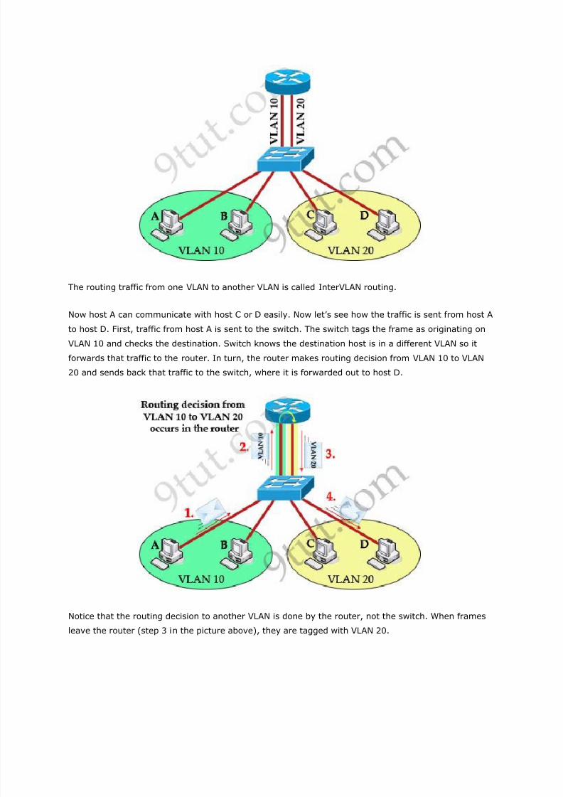
The routing traffic from one VLAN to another VLAN is called InterVLAN routing.
Now host A can communicate with host C or D easily. Now let’s see how the traffic is sent from host A
to host D. First, traffic from host A is sent to the switch. The switch tags the frame as originating on
VLAN 10 and checks the destination. Switch knows the destination host is in a different VLAN so it
forwards that traffic to the router. In turn, the router makes routing decision from VLAN 10 to VLAN
20 and sends back that traffic to the switch, where it is forwarded out to host D.
Notice that the routing decision to another VLAN is done by the router, not the switch. When frames
leave the router (step 3 in the picture above), they are tagged with VLAN 20.
7/29/2019 VLAN Introduction
http://slidepdf.com/reader/full/vlan-introduction 9/21
Also notice that receiving ends (host A & D in this case) are unaware of any VLAN information. Switch
attaches VLAN information when receiving frames from host A and removes VLAN information before
forwarding to host D.
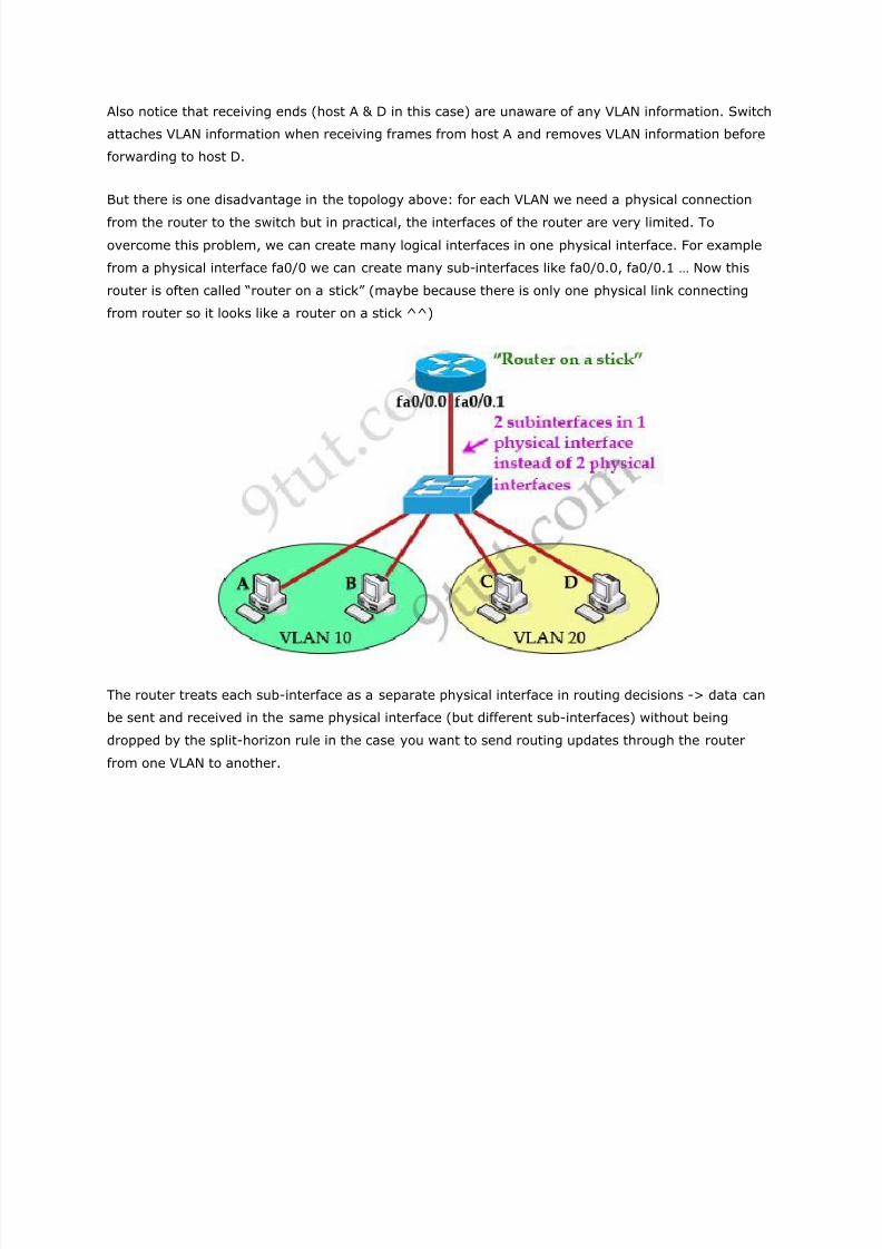
But there is one disadvantage in the topology above: for each VLAN we need a physical connection
from the router to the switch but in practical, the interfaces of the router are very limited. To
overcome this problem, we can create many logical interfaces in one physical interface. For example
from a physical interface fa0/0 we can create many sub-interfaces like fa0/0.0, fa0/0.1 … Now this
router is often called ―router on a stick‖ (maybe because there is only one physical link connecting
from router so it looks like a router on a stick ^^)
The router treats each sub-interface as a separate physical interface in routing decisions -> data can
be sent and received in the same physical interface (but different sub-interfaces) without being
dropped by the split-horizon rule in the case you want to send routing updates through the router
from one VLAN to another.
7/29/2019 VLAN Introduction
http://slidepdf.com/reader/full/vlan-introduction 10/21
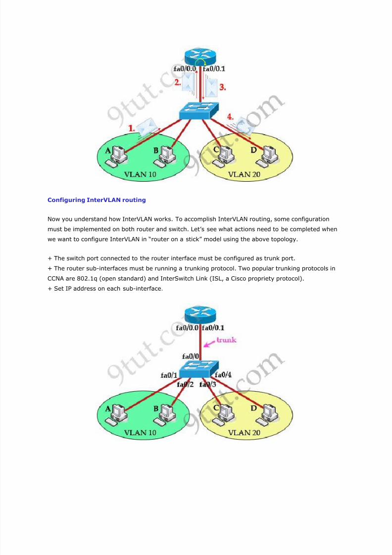
Configuring InterVLAN routing
Now you understand how InterVLAN works. To accomplish InterVLAN routing, some configuration
must be implemented on both router and switch. Let’s see what actions need to be completed when
we want to configure InterVLAN in ―router on a stick‖ model using the above topology.
+ The switch port connected to the router interface must be configured as trunk port.
+ The router sub-interfaces must be running a trunking protocol. Two popular trunking protocols in
CCNA are 802.1q (open standard) and InterSwitch Link (ISL, a Cisco propriety protocol).
+ Set IP address on each sub-interface.
7/29/2019 VLAN Introduction
http://slidepdf.com/reader/full/vlan-introduction 11/21
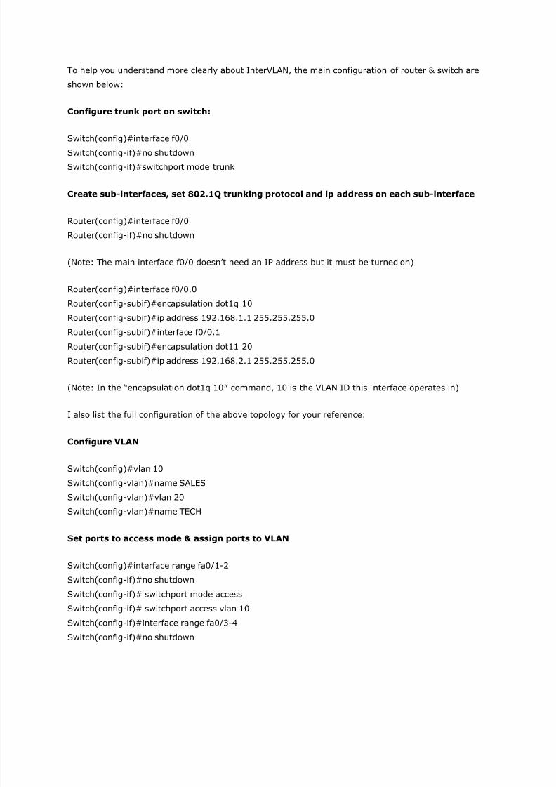
To help you understand more clearly about InterVLAN, the main configuration of router & switch are
shown below:
Configure trunk port on switch:
Switch(config)#interface f0/0
Switch(config-if)#no shutdown
Switch(config-if)#switchport mode trunk
Create sub-interfaces, set 802.1Q trunking protocol and ip address on each sub-interface
Router(config)#interface f0/0
Router(config-if)#no shutdown
(Note: The main interface f0/0 doesn’t need an IP address but it must be turned on)
Router(config)#interface f0/0.0
Router(config-subif)#encapsulation dot1q 10
Router(config-subif)#ip address 192.168.1.1 255.255.255.0
Router(config-subif)#interface f0/0.1
Router(config-subif)#encapsulation dot11 20
Router(config-subif)#ip address 192.168.2.1 255.255.255.0
(Note: In the ―encapsulation dot1q 10″ command, 10 is the VLAN ID this interface operates in)
I also list the full configuration of the above topology for your reference:
Configure VLAN
Switch(config)#vlan 10
Switch(config-vlan)#name SALES
Switch(config-vlan)#vlan 20
Switch(config-vlan)#name TECH
Set ports to access mode & assign ports to VLAN
Switch(config)#interface range fa0/1-2
Switch(config-if)#no shutdown
Switch(config-if)# switchport mode access
Switch(config-if)# switchport access vlan 10
Switch(config-if)#interface range fa0/3-4
Switch(config-if)#no shutdown
7/29/2019 VLAN Introduction
http://slidepdf.com/reader/full/vlan-introduction 12/21
Switch(config-if)#switchport mode access
Switch(config-if)# switchport access vlan 20
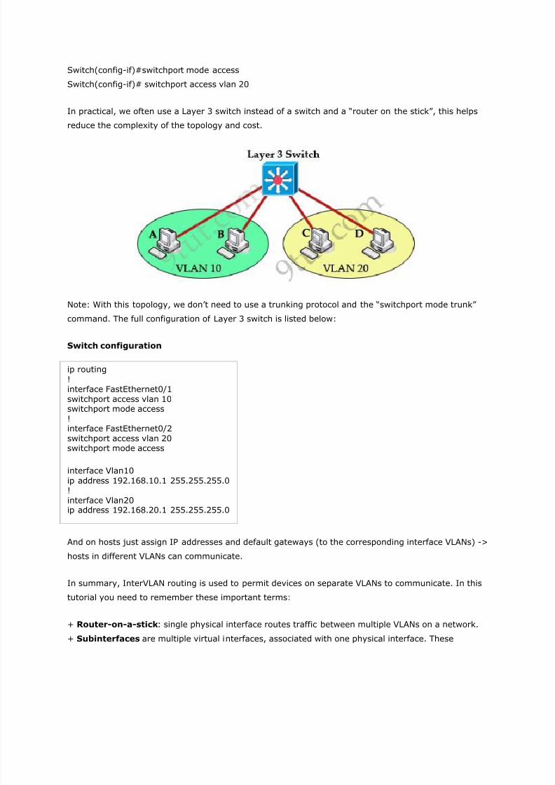
In practical, we often use a Layer 3 switch instead of a switch and a ―router on the stick‖, this helps
reduce the complexity of the topology and cost.
Note: With this topology, we don’t need to use a trunking protocol and the ―switchport mode trunk‖
command. The full configuration of Layer 3 switch is listed below:
Switch configuration
ip routing
!interface FastEthernet0/1switchport access vlan 10
switchport mode access!interface FastEthernet0/2switchport access vlan 20switchport mode access
interface Vlan10
ip address 192.168.10.1 255.255.255.0!interface Vlan20ip address 192.168.20.1 255.255.255.0
And on hosts just assign IP addresses and default gateways (to the corresponding interface VLANs) ->
hosts in different VLANs can communicate.
In summary, InterVLAN routing is used to permit devices on separate VLANs to communicate. In this
tutorial you need to remember these important terms:
+ Router-on-a-stick: single physical interface routes traffic between multiple VLANs on a network.
+ Subinterfaces are multiple virtual interfaces, associated with one physical interface. These
7/29/2019 VLAN Introduction
http://slidepdf.com/reader/full/vlan-introduction 13/21
subinterfaces are configured in software on a router that is independently configured with an IP
address and VLAN assignment.
Comments
1. a.daqare
February 24th, 2012
thank you this is really good information. Keep up the good work
2. Bob
February 26th, 2012
its wonderful… congrats!!!
3. Jien
February 27th, 2012
Hi, there are minor wrong word on ―Create sub-interfaces, set 802.1Q trunking protocol and ipaddress on each sub-interface‖
Router(config)#interface f0/0Router(config-if)#no shutdown
(Note: The main interface f0/0 doesn’t need an IP address but it must be turned on)
Router(config-if)#interface f0/0.0 (before create the sub interface, it suppose still in interfacemode)
Router(config-subif)#encapsulation dot1q 10Router(config-subif)#ip address 192.168.1.1 255.255.255.0Router(config-subif)#interface f0/0.1Router(config-subif)#encapsulation dot1q 20 (i amend to dot1q, as u wrote to dot11)Router(config-subif)#ip address 192.168.2.1 255.255.255.0
Correct me if i am wrong, I am new to CCNA. :-)
4. 9tut
March 1st, 2012
@Jien: Yes, it is a mistake in my tutorial. Thanks for your detection. I updated it!
5. Koogen
March 8th, 2012
Excellent stuff, thanks alot mate.
6. AGP
7/29/2019 VLAN Introduction
http://slidepdf.com/reader/full/vlan-introduction 14/21
March 12th, 2012
hi 9tut, i just did the Layer 3 switch configs just as shown on the figure…but still hosts on VLAN10 cannot communicate with VLAN 20, but both hosts on each VLANs can ping there owngateway. Was there any missing additional commands on the figure? thanks alot…
7.
9tut
March 12th, 2012
@AGP: Did you assign the default gateway on the PC?
8. AGP
March 12th, 2012
@9tut: yup i assign the default gateway on the PCs?
By the way, i already figured it out… I haven’t enable this command on the Layer 3 switch…
switch(config)#ip routing
Please include this command in the figure, because other newbies might not figure it out thateasily….
By default, Layer 3 switches functions as Layer 2 switches unless its routing capabilities areenabled…
Thanks alot 9tut!
9. 9tut
March 13th, 2012
@AGP: That command was added in the ―Switch Configuration‖ (the first line).
10. tchuembou
March 16th, 2012
sorry i would like to know how can i explain my problem
11. Anonymous
March 31st, 2012
Please can anyone send me ( [email protected] ) the latest. SIMS / LABS Questions onCCNA Exams, I am writing next week.Thx
12. Blake
7/29/2019 VLAN Introduction
http://slidepdf.com/reader/full/vlan-introduction 15/21
April 1st, 2012
Hello 9tut, I was wondering if your layer-3 switch configuration was incomplete. Don’t you haveto configure each of the four ports attached to the switch, as was done in the ―router on a stick‖ configuration?
Switch configuration
ip routing!interface FastEthernet0/1 (Should be: interface range fa0/1-2)switchport access vlan 10switchport mode access!interface FastEthernet0/2 (Should be: interface range fa0/3-4)switchport access vlan 20switchport mode access!
Please let me know if I am missing something.
Thank you for all of your hard work. Your site is very helpful.
13. 9tut
April 1st, 2012
@Blake: Yes, the above configuration is only an example of configuring two hosts in differentVLANs. In fact you have to do it on 4 interfaces.
14. zoop
April 17th, 2012
good work man..:)
15. Norshamila
April 22nd, 2012
Ya thats what I’m here for Matt. Thank you for your comment too, sorry for the late reply, but Iellary do appreciate you stopping by and leaving a quick note. It helps fuel my motivation tokeep going. I hope I was able to help and move you closer to your next Cisco Certification.
16. janjo
May 7th, 2012
SPLENDID!!! Thank you for this wonderful information.
Cheers!!
17. Having problem.
7/29/2019 VLAN Introduction
http://slidepdf.com/reader/full/vlan-introduction 16/21
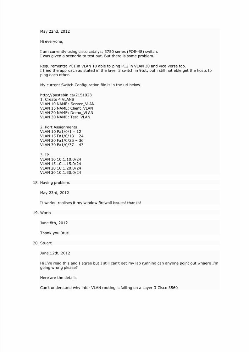
May 22nd, 2012
Hi everyone,
I am currently using cisco catalyst 3750 series (POE-48) switch.I was given a scenario to test out. But there is some problem.
Requirements: PC1 in VLAN 10 able to ping PC2 in VLAN 30 and vice versa too.I tried the approach as stated in the layer 3 switch in 9tut, but i still not able get the hosts toping each other.
My current Switch Configuration file is in the url below.
http://pastebin.ca/21519231. Create 4 VLANSVLAN 10 NAME: Server_VLANVLAN 15 NAME: Client_VLANVLAN 20 NAME: Demo_VLANVLAN 30 NAME: Test_VLAN
2. Port AssignmentsVLAN 10 Fa1/0/1 – 12VLAN 15 Fa1/0/13 – 24
VLAN 20 Fa1/0/25 – 36VLAN 30 Fa1/0/37 – 43
3. IPVLAN 10 10.1.10.0/24VLAN 15 10.1.15.0/24VLAN 20 10.1.20.0/24VLAN 30 10.1.30.0/24
18. Having problem.
May 23rd, 2012
It works! realises it my window firewall issues! thanks!
19. Wario
June 8th, 2012
Thank you 9tut!
20. Stuart
June 12th, 2012
Hi I’ve read this and I agree but I still can’t get my lab running can anyone point out whaere I’mgoing wrong please?
Here are the details
Can’t understand why inter VLAN routing is failing on a Layer 3 Cisco 3560
7/29/2019 VLAN Introduction
http://slidepdf.com/reader/full/vlan-introduction 17/21
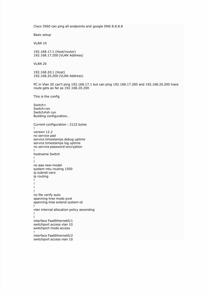
Cisco 3560 can ping all endpoints and google DNS 8.8.8.8
Basic setup
VLAN 10
192.168.17.1 (Host/router)192.168.17.200 (VLAN Address)
VLAN 20
192.168.20.1 (Host)192.168.20.200 (VLAN Address)
PC in Vlan 20 can’t ping 192.168.17.1 but can ping 192.168.17.200 and 192.168.20.200 traceroute gets as far as 192.168.20.200
This is the config
Switch>Switch>enSwitch#sh runBuilding configuration…
Current configuration : 2122 bytes!version 12.2no service padservice timestamps debug uptimeservice timestamps log uptimeno service password-encryption!
hostname Switch!!no aaa new-modelsystem mtu routing 1500ip subnet-zeroip routing!
!!!no file verify autospanning-tree mode pvstspanning-tree extend system-id
!vlan internal allocation policy ascending!!interface FastEthernet0/1switchport access vlan 10switchport mode access
!interface FastEthernet0/2switchport access vlan 10
7/29/2019 VLAN Introduction
http://slidepdf.com/reader/full/vlan-introduction 18/21
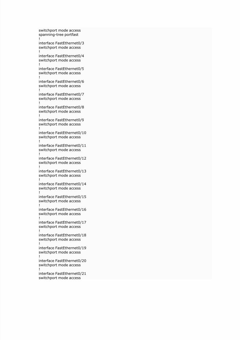
switchport mode accessspanning-tree portfast!interface FastEthernet0/3
switchport mode access!interface FastEthernet0/4
switchport mode access!interface FastEthernet0/5switchport mode access
!interface FastEthernet0/6switchport mode access!interface FastEthernet0/7switchport mode access
!interface FastEthernet0/8switchport mode access!
interface FastEthernet0/9switchport mode access!
interface FastEthernet0/10switchport mode access!interface FastEthernet0/11switchport mode access!interface FastEthernet0/12switchport mode access!interface FastEthernet0/13switchport mode access
!interface FastEthernet0/14switchport mode access!interface FastEthernet0/15switchport mode access!interface FastEthernet0/16switchport mode access!interface FastEthernet0/17switchport mode access!interface FastEthernet0/18
switchport mode access!interface FastEthernet0/19switchport mode access!interface FastEthernet0/20switchport mode access!interface FastEthernet0/21switchport mode access
7/29/2019 VLAN Introduction
http://slidepdf.com/reader/full/vlan-introduction 19/21
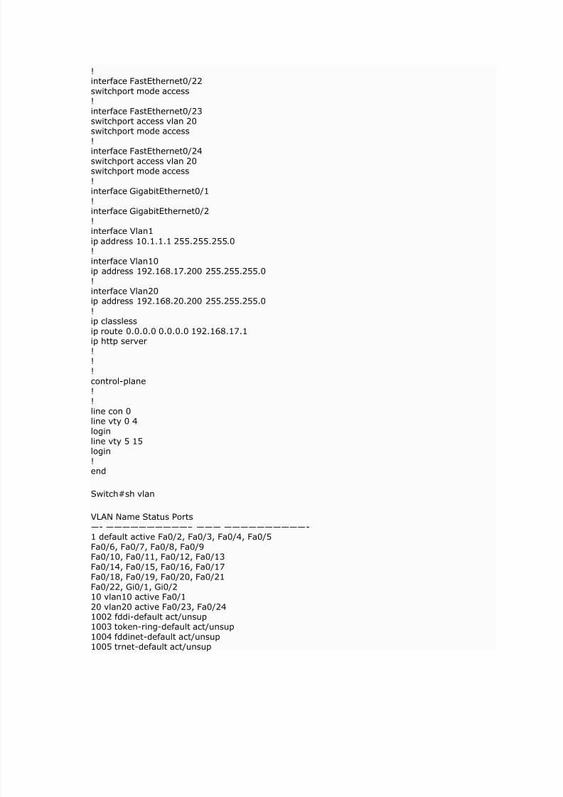
!interface FastEthernet0/22switchport mode access!
interface FastEthernet0/23switchport access vlan 20switchport mode access
!interface FastEthernet0/24switchport access vlan 20switchport mode access
!interface GigabitEthernet0/1!interface GigabitEthernet0/2!interface Vlan1
ip address 10.1.1.1 255.255.255.0!interface Vlan10ip address 192.168.17.200 255.255.255.0
!interface Vlan20ip address 192.168.20.200 255.255.255.0
!ip classlessip route 0.0.0.0 0.0.0.0 192.168.17.1ip http server!!!control-plane!!line con 0
line vty 0 4loginline vty 5 15login!end
Switch#sh vlan
VLAN Name Status Ports—- ——————————– ——— ——————————-1 default active Fa0/2, Fa0/3, Fa0/4, Fa0/5Fa0/6, Fa0/7, Fa0/8, Fa0/9
Fa0/10, Fa0/11, Fa0/12, Fa0/13Fa0/14, Fa0/15, Fa0/16, Fa0/17Fa0/18, Fa0/19, Fa0/20, Fa0/21Fa0/22, Gi0/1, Gi0/210 vlan10 active Fa0/120 vlan20 active Fa0/23, Fa0/241002 fddi-default act/unsup1003 token-ring-default act/unsup1004 fddinet-default act/unsup1005 trnet-default act/unsup
7/29/2019 VLAN Introduction
http://slidepdf.com/reader/full/vlan-introduction 20/21
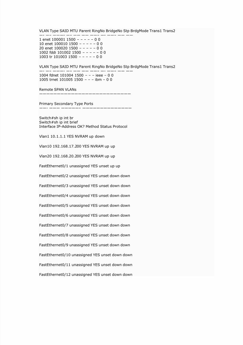
VLAN Type SAID MTU Parent RingNo BridgeNo Stp BrdgMode Trans1 Trans2—- —– ———- —– —— —— ——– —- ——– —— —— 1 enet 100001 1500 – – – – – 0 010 enet 100010 1500 – – – – – 0 0
20 enet 100020 1500 – – – – – 0 01002 fddi 101002 1500 – – – – – 0 01003 tr 101003 1500 – – – – – 0 0
VLAN Type SAID MTU Parent RingNo BridgeNo Stp BrdgMode Trans1 Trans2—- —– ———- —– —— —— ——– —- ——– —— —— 1004 fdnet 101004 1500 – – – ieee – 0 01005 trnet 101005 1500 – – – ibm – 0 0
Remote SPAN VLANs——————————————————————————
Primary Secondary Type Ports——- ——— —————– ——————————————
Switch#sh ip int br
Switch#sh ip int brief Interface IP-Address OK? Method Status Protocol
Vlan1 10.1.1.1 YES NVRAM up down
Vlan10 192.168.17.200 YES NVRAM up up
Vlan20 192.168.20.200 YES NVRAM up up
FastEthernet0/1 unassigned YES unset up up
FastEthernet0/2 unassigned YES unset down down
FastEthernet0/3 unassigned YES unset down down
FastEthernet0/4 unassigned YES unset down down
FastEthernet0/5 unassigned YES unset down down
FastEthernet0/6 unassigned YES unset down down
FastEthernet0/7 unassigned YES unset down down
FastEthernet0/8 unassigned YES unset down down
FastEthernet0/9 unassigned YES unset down down
FastEthernet0/10 unassigned YES unset down down
FastEthernet0/11 unassigned YES unset down down
FastEthernet0/12 unassigned YES unset down down
7/29/2019 VLAN Introduction
http://slidepdf.com/reader/full/vlan-introduction 21/21
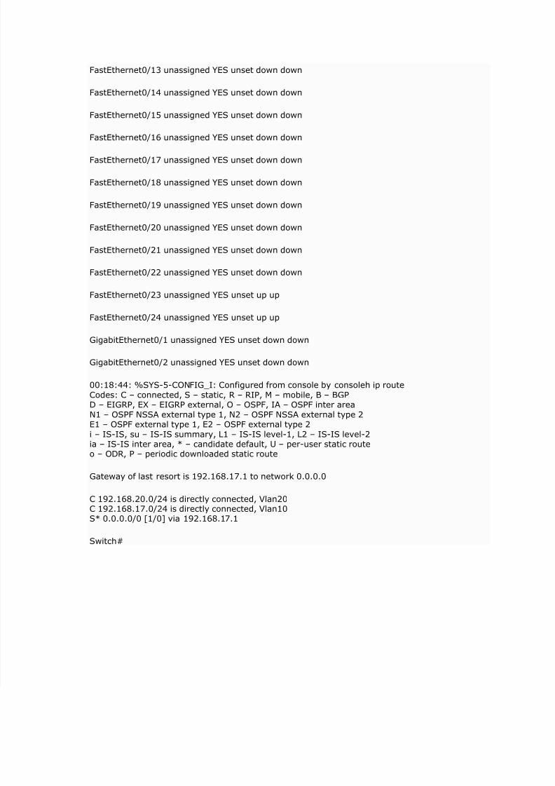
FastEthernet0/13 unassigned YES unset down down
FastEthernet0/14 unassigned YES unset down down
FastEthernet0/15 unassigned YES unset down down
FastEthernet0/16 unassigned YES unset down down
FastEthernet0/17 unassigned YES unset down down
FastEthernet0/18 unassigned YES unset down down
FastEthernet0/19 unassigned YES unset down down
FastEthernet0/20 unassigned YES unset down down
FastEthernet0/21 unassigned YES unset down down
FastEthernet0/22 unassigned YES unset down down
FastEthernet0/23 unassigned YES unset up up
FastEthernet0/24 unassigned YES unset up up
GigabitEthernet0/1 unassigned YES unset down down
GigabitEthernet0/2 unassigned YES unset down down
00:18:44: %SYS-5-CONFIG_I: Configured from console by consoleh ip routeCodes: C – connected, S – static, R – RIP, M – mobile, B – BGPD – EIGRP, EX – EIGRP external, O – OSPF, IA – OSPF inter area
N1 – OSPF NSSA external type 1, N2 – OSPF NSSA external type 2E1 – OSPF external type 1, E2 – OSPF external type 2i – IS-IS, su – IS-IS summary, L1 – IS-IS level-1, L2 – IS-IS level-2ia – IS-IS inter area, * – candidate default, U – per-user static routeo – ODR, P – periodic downloaded static route
Gateway of last resort is 192.168.17.1 to network 0.0.0.0
C 192.168.20.0/24 is directly connected, Vlan20C 192.168.17.0/24 is directly connected, Vlan10S* 0.0.0.0/0 [1/0] via 192.168.17.1
Switch#