Embed Size (px)
DESCRIPTION
VIVOTEK VAST is the professional video / central management software designed for managingall VIVOTEK IP surveillance products with intuitive functions and numerous features. It supportshundreds of cameras and stations in a hierarchical structure of system for monitoring, recording,playback and event trigger management with ease-of-use and efficient control. Moreover, VASTalso offers the video wall solution, VAST Matrix, for hundreds of cameras live view monitoring.VAST integrates VIVOTEK network cameras to provide diverse solutions and applications, suchas seamless recording with the cameras for uninterrupted video recording and Panoramic PTZfor 360° seamless surveillance solution. VAST performs remote management with full range ofthe server & client structure and constitutes a robust system for various applications, such asstores, banking and the public space.
Citation preview
VIVOTEK - A Leading Provider of Multimedia Communication Solutions
User's Manual - 1
Rev.: 1.11

VIVOTEK - A Leading Provider of Multimedia Communication Solutions
2 - User's Manual
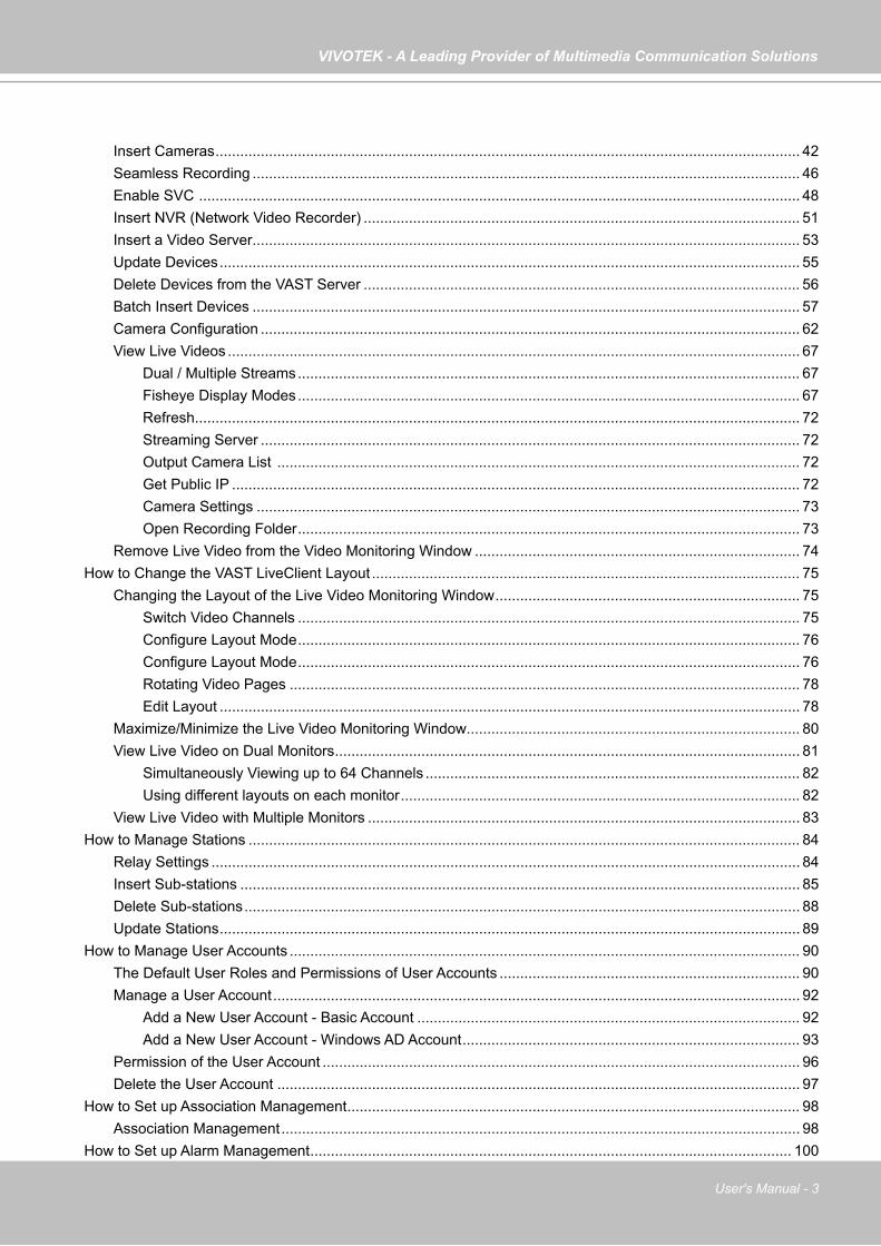
Table of Contents
Revision History ..................................................................................................................................................... 8
Getting Started .......................................................................................................................................................... 11
Introducing VAST .................................................................................................................................................. 11New Features ................................................................................................................................................ 11Key Features ................................................................................................................................................. 11
VAST Server and Client Components .................................................................................................................. 12Usage Scenario .................................................................................................................................................... 12Technical Specifications ....................................................................................................................................... 13VAST Server Functionality .................................................................................................................................... 14VAST LiveClient Functionality .............................................................................................................................. 15VAST Playback Functionality ................................................................................................................................ 16Minimum System Requirements .......................................................................................................................... 17VAST Software License ........................................................................................................................................ 19Reminders for VAST Software License ................................................................................................................ 20
VAST Installation ....................................................................................................................................................... 22
Installing the VAST Software ................................................................................................................................ 22
VAST Server .............................................................................................................................................................. 26
Activating the VAST Server .................................................................................................................................. 26How to Configure the Server ................................................................................................................................ 26How to Stop/Reboot the Server ............................................................................................................................ 26
VAST LiveClient Configuration .................................................................................................................................. 27
Activating the VAST LiveClient and Logging in to a VAST Server ........................................................................ 27VAST LiveClient User Interface ............................................................................................................................ 28
Menu Bar ....................................................................................................................................................... 28Status Panel .................................................................................................................................................. 29
Help Panel ............................................................................................................................................................ 30Quick Access Bar .......................................................................................................................................... 31Live Video Monitoring Window ...................................................................................................................... 31Hierarchical Management Tree ..................................................................................................................... 32Camera Control Panel ................................................................................................................................... 33
Pan/Tilt/Zoom (PTZ) Control Panel ........................................................................................................ 33Two Way Audio Control Panel ................................................................................................................ 35Language Selection ............................................................................................................................... 35
Alarm Window ............................................................................................................................................... 36Alarm Filter ............................................................................................................................................. 37Alarm State ............................................................................................................................................ 38
Instant Playback ............................................................................................................................................ 39Instant Replay ............................................................................................................................................... 40Audio Control ................................................................................................................................................ 41
How to Manage Devices ...................................................................................................................................... 42
VIVOTEK - A Leading Provider of Multimedia Communication Solutions
User's Manual - 3
Insert Cameras .............................................................................................................................................. 42Seamless Recording ..................................................................................................................................... 46Enable SVC .................................................................................................................................................. 48Insert NVR (Network Video Recorder) .......................................................................................................... 51Insert a Video Server ..................................................................................................................................... 53Update Devices ............................................................................................................................................. 55Delete Devices from the VAST Server .......................................................................................................... 56Batch Insert Devices ..................................................................................................................................... 57Camera Configuration ................................................................................................................................... 62View Live Videos ........................................................................................................................................... 67
Dual / Multiple Streams .......................................................................................................................... 67Fisheye Display Modes .......................................................................................................................... 67Refresh ................................................................................................................................................... 72Streaming Server ................................................................................................................................... 72Output Camera List ............................................................................................................................... 72Get Public IP .......................................................................................................................................... 72Camera Settings .................................................................................................................................... 73Open Recording Folder .......................................................................................................................... 73
Remove Live Video from the Video Monitoring Window ............................................................................... 74How to Change the VAST LiveClient Layout ........................................................................................................ 75
Changing the Layout of the Live Video Monitoring Window .......................................................................... 75Switch Video Channels .......................................................................................................................... 75Configure Layout Mode .......................................................................................................................... 76Configure Layout Mode .......................................................................................................................... 76Rotating Video Pages ............................................................................................................................ 78Edit Layout ............................................................................................................................................. 78
Maximize/Minimize the Live Video Monitoring Window ................................................................................. 80View Live Video on Dual Monitors ................................................................................................................. 81
Simultaneously Viewing up to 64 Channels ........................................................................................... 82Using different layouts on each monitor ................................................................................................. 82
View Live Video with Multiple Monitors ......................................................................................................... 83How to Manage Stations ...................................................................................................................................... 84
Relay Settings ............................................................................................................................................... 84Insert Sub-stations ........................................................................................................................................ 85Delete Sub-stations ....................................................................................................................................... 88Update Stations ............................................................................................................................................. 89
How to Manage User Accounts ............................................................................................................................ 90The Default User Roles and Permissions of User Accounts ......................................................................... 90Manage a User Account ................................................................................................................................ 92
Add a New User Account - Basic Account ............................................................................................. 92Add a New User Account - Windows AD Account .................................................................................. 93
Permission of the User Account .................................................................................................................... 96Delete the User Account ............................................................................................................................... 97
How to Set up Association Management .............................................................................................................. 98Association Management .............................................................................................................................. 98
How to Set up Alarm Management ..................................................................................................................... 100
VIVOTEK - A Leading Provider of Multimedia Communication Solutions
4 - User's Manual
Alarm Management ..................................................................................................................................... 100How to Manage the Virtual Matrix ...................................................................................................................... 108
The architecture of VAST Matrix ................................................................................................................. 108Installing VAST Matrix Program .................................................................................................................. 109Launching VAST Matrix ............................................................................................................................... 110
Configuration .........................................................................................................................................111View Settings ........................................................................................................................................111About .....................................................................................................................................................111Exit ........................................................................................................................................................111
VAST Matrix Management .......................................................................................................................... 112Matrix Management Settings ............................................................................................................... 112Manage VAST Matrix through VAST LiveClient ................................................................................... 113
Matrix View Settings .................................................................................................................................... 114Search VIVOCam Switches ............................................................................................................................... 115How to Configure the Station General Settings .................................................................................................. 116
Server Settings ............................................................................................................................................ 116Log Settings ................................................................................................................................................ 116
How to Configure Station Network Settings ....................................................................................................... 117Port Settings ................................................................................................................................................ 117UPnP Settings ............................................................................................................................................. 117Proxy Settings ............................................................................................................................................. 117Web Access Settings ................................................................................................................................... 117
How to Edit Recording Groups ........................................................................................................................... 118Recording Storage Settings ........................................................................................................................ 118
Default Storage Group Settings ........................................................................................................... 119Add New Recording Group(s) .............................................................................................................. 121
How to Edit Recording Schedules ...................................................................................................................... 122Edit Schedule List ....................................................................................................................................... 123
Add Schedules ..................................................................................................................................... 123Rename Schedules .............................................................................................................................. 123Delete Schedules ................................................................................................................................. 123Load/Save Schedule Templates ........................................................................................................... 124
Edit Camera List .......................................................................................................................................... 125Edit Time Frame List ................................................................................................................................... 126
Add New Time Frames ......................................................................................................................... 127Recording Settings ............................................................................................................................... 128
The Concept of Repeat Frequency ............................................................................................................. 130Repeat Frequency: Daily Setting ......................................................................................................... 131Repeat Frequency: Weekly Setting (Day-based) ................................................................................. 134Repeat Frequency: Monthly Setting (Day-based) ................................................................................ 137Repeat Frequency: Yearly Setting (Day-based) ................................................................................... 139
How to Manually Begin /Stop Recording ............................................................................................................ 141How to Edit Scheduled Backup Settings ............................................................................................................ 142
Select Backup Source ................................................................................................................................. 142Setup Backup Schedule .............................................................................................................................. 143Select Backup Target .................................................................................................................................. 143Other Options .............................................................................................................................................. 143
VIVOTEK - A Leading Provider of Multimedia Communication Solutions
User's Manual - 5
How to Configure Station Server Settings ..........................................................................................................144DDNS Settings ............................................................................................................................................144Network Storage Server Settings ................................................................................................................145SMTP Settings ............................................................................................................................................146
How to Use the Talk Panel .................................................................................................................................147Add a Camera to the Talk Panel ..................................................................................................................147Remove a Camera from the Talk Panel ......................................................................................................149
How to Configure E-map Settings ......................................................................................................................150Upload an E-map ........................................................................................................................................150User Interface of E-map Settings Page (View Mode) ..................................................................................151
Quick Access Bar .................................................................................................................................152Status Panel .........................................................................................................................................152
User Interface of E-map Settings Page (Edit Mode) ...................................................................................153Device Management ...................................................................................................................................154Live View Dialog Settings ............................................................................................................................155
Open Live View Dialog .........................................................................................................................155Send to Single View .............................................................................................................................155
E-map Link ..................................................................................................................................................156How to Configure Client Settings .......................................................................................................................159
Snapshot Settings .......................................................................................................................................159Take a Snapshot ..................................................................................................................................160
Recording Settings ......................................................................................................................................161Type 1: Record to EXE ........................................................................................................................161Type 2: Record to 3GP .........................................................................................................................161Type 3: Record to AVI ..........................................................................................................................162Built-in Media Player--EXE ...................................................................................................................165
View Settings ...............................................................................................................................................167Display Location ...................................................................................................................................167Date and Time Format .........................................................................................................................168Video Display Mode .............................................................................................................................168Font Settings ........................................................................................................................................169
General Settings .........................................................................................................................................170System Settings ...................................................................................................................................170Alarm Settings ......................................................................................................................................171Rotation Settings ..................................................................................................................................171Display Settings ...................................................................................................................................172
Joystick Settings .........................................................................................................................................174Enable Joystick ....................................................................................................................................174
Proxy Settings .............................................................................................................................................180How to Use PiP (Picture-in-Picture) ...................................................................................................................181
Enable PiP ...................................................................................................................................................181Global View ..........................................................................................................................................181ROI (Region of Interest) .......................................................................................................................182Digital Zoom In .....................................................................................................................................182Snapshot & Print Zoomed In Image .....................................................................................................182PiP Settings ..........................................................................................................................................182Multi-touch Mode ..................................................................................................................................183

VIVOTEK - A Leading Provider of Multimedia Communication Solutions
6 - User's Manual
How to Configure Video Enhancement ..............................................................................................................184Basic Image Adjustment ..............................................................................................................................184Defog ...........................................................................................................................................................186
Apply a Preset Defog Profile ................................................................................................................186Create a New Defog Profile .................................................................................................................187
How to Search for a Device on the Hierarchical Management Tree ..................................................................189How to Print a Video Image ................................................................................................................................190How to Lock LiveClient for Security Concerns ...................................................................................................190How to Log out from the VAST Server ...............................................................................................................191How to Exit VAST LiveClient ..............................................................................................................................191How to Configure a Logical Tree ........................................................................................................................192
VAST Playback Configuration .................................................................................................................................199
Activating VAST Playback and Logging in to a Server .......................................................................................199VAST Playback User Interface ...........................................................................................................................200
Menu Bar .....................................................................................................................................................200Status Panel ................................................................................................................................................200Quick Access Bar ........................................................................................................................................201Recorded Video Playback Window .............................................................................................................201Language Selection ....................................................................................................................................202Query Panel-- Browsing Page .....................................................................................................................202Query Panel--Time Search Page ................................................................................................................204Query Panel--Event Search Page ...............................................................................................................205Query Panel--Bookmark Search Page ........................................................................................................206Query Panel--Alarm Search Page ...............................................................................................................207Query Panel--Log Viewer Page ...................................................................................................................208Video Clips List Window ..............................................................................................................................209Playback Control Panel ...............................................................................................................................210Rewind ........................................................................................................................................................211
How to Playback Recorded Video ......................................................................................................................212Select a Recorded Video Clip .....................................................................................................................212Remove Recorded Video Clips from Video Cells ........................................................................................214Timeline Slider Bar and Histogram ..............................................................................................................214Zoom in / out of the Histogram ....................................................................................................................215Synchronous Playback ................................................................................................................................216Audio Control ..............................................................................................................................................218
How to Change the Playback Layout .................................................................................................................219Changing the Layout of the Recorded Video Playback Window .................................................................219
Switch Video Channels ........................................................................................................................219Configure Layout Mode ........................................................................................................................219
Maximize/Minimize the Recorded Video Playback Window ........................................................................220View Recorded Video with Multiple Monitors ..............................................................................................221
How to Backup Recorded Video ........................................................................................................................222How to Search for a Video Clip in a Specific Period of time ...............................................................................228How to Add a Bookmark .....................................................................................................................................229How to Search for Events ...................................................................................................................................230
Select Event Category ................................................................................................................................231
VIVOTEK - A Leading Provider of Multimedia Communication Solutions
User's Manual - 7
Event Category- All Events ..................................................................................................................231Event Category- All Motion Events.......................................................................................................231Event Category- All IVA events ............................................................................................................232Event Category- All DI Events ..............................................................................................................232Event Category- Named DI Events ......................................................................................................233
Start Event Search ......................................................................................................................................234Backup the Event Videos ............................................................................................................................235
How to Search for a Bookmark ..........................................................................................................................236How to Search Logs ...........................................................................................................................................237
Select Log Category/Log Type/Log Level ...................................................................................................238Search All Local Logs...........................................................................................................................239Search Login History ............................................................................................................................239Search Login Activities .........................................................................................................................240
How to Configure Client Settings .......................................................................................................................242Snapshot Settings .......................................................................................................................................242Export Settings ............................................................................................................................................242View Settings ...............................................................................................................................................244Proxy Settings .............................................................................................................................................244General Settings .........................................................................................................................................244
System Settings ...................................................................................................................................244Display Settings ...................................................................................................................................244
How to Configure Video Enhancement ..............................................................................................................244How to Search for a Device on the Hierarchical Management Tree ..................................................................244How to Print a Video Image ................................................................................................................................244How to Lock VAST Playback for Security Concerns ..........................................................................................245How to Log out from the VAST Server ...............................................................................................................245How to Exit VAST Playback ................................................................................................................................245
Import and Export Utility ..........................................................................................................................................246
Export Utility .......................................................................................................................................................246Import Utility .......................................................................................................................................................246
VAST Service Control Tool ......................................................................................................................................248
Appendix A Panoramic PTZ (P-PTZ) Configuration ................................................................................................249
Enable Panoramic PTZ on VAST ......................................................................................................................249Panoramic PTZ - Event Trigger .........................................................................................................................252Enable or Disable the Panoramic PTZ Functions .............................................................................................254
Appendix B ONVIF Support.....................................................................................................................................255
Appendix C Support for Digital I/O Modbus TCP Modules ......................................................................................257
Appendix D Other Parameters ................................................................................................................................262

VIVOTEK - A Leading Provider of Multimedia Communication Solutions
8 - User's Manual
Revision HistoryRev. 1.5.2:
* VAST now supports Video Servers VS8801 & VS8401, and NVR servers NR8201 & NR8301.
* Automatically saves the last layout when the management session is closed (for both LiveClient and Playback).
* Added Playback as one of user's previlege options.* A web session with an individual camera can be launched by a double-click on a camera's
icon.
Rev. 1.6.1:* Added description for Adaptive Frame Rate Adjustment with the new SVC codec cameras. * Added description for Auto Stream Size functionality. * Added functionalities related to FE8171V fisheye camera. * Added description for fisheye-specific screen control and playback functions.* Replaced some description for the changes/improvements made on the user interface.* Modified the graphic size limitation of E-map upload from 5MB to 2MB.
Rev. 1.6.18:* Corrected editorial errors and added a conceptual drawing for the SVC-T (Temporal) func-
tion.
Rev. 1.6.1.11:* Changed the maximum number of channel number in trial mode to 256.
Rev. 1.7.7:* Added description for the Bookmark function.* Added functional description related to the Panoramic PTZ feature in Appendix A. * Added description for the Instant Replay function. * Reflected changes on the new display and layout design. * Added Hot key combinations. * Removed the 1P3R fisheye display mode, which was removed from specifications later.
Rev. 1.8:* Added individual Motion detection window options in the Event Management configuration
(see page 101). * Added description for new Export video clips function. * Added support for user accounts from Windows AD (Active Directory) service. (see page
93).* Added G.726 audio codec support.
VIVOTEK - A Leading Provider of Multimedia Communication Solutions
User's Manual - 9
* Added digital input options in the Recording Schedule settings. (see page 129)* Added contents for the support of ONVIF rev. 2.2 in Appendix C (see page 255). * Added new PTZ control options (speed and continuous move) for speed dome cameras. (see
page 34). * Added description for the Seamless Recording function. (see page 46).* User management: increased the number of configurable users to 1,024. * Added the Device Pack update option (see page 30).
Rev. 1.9:* Renamed and re-organized the Event Management window into the Alarm Management
windows. The Filter function is added. (see page 101). * Added description for the vertical layouts. (see page 76). * Added description for the Video mode option (see page 62). * Added description for the common user name and password for multiple cameras (see page
61. * Added the Sort devices by name option (see page 171). * Added Storage lost as a system log type. * Added description for the Alarm search function (see page 207). * Added Appendix C for the I/O box support (Digital I/O Modbus TCP Modules). (see page
257). * Added the Auto tracking button (see page 33). * Added description of the new implementation for multiple event screens on video alarms (see
page 105).
Rev. 1.10:* Added the ONVIF Batch Insert feature (see page 57). * Added the show VCA rules setting in View settings (see page 168). Note that VCA rules are
not displayed on the Matrix view. * Added information for the Logical Tree configuration (see page 192). * Added the video clip information - resolution/codec/fps/model name/IP/throughput. * Added the feature for enabling/disabling Server GUID while importing VAST configuration.
(see page 246). * Moved Appendix C ONVIF support to page 255. Moved Appendix D Digital I/O Modbus TCP
Modules to page 257. * Added Line Crossing and Field Detection as the triggering conditions in Recording Schedule
setting. * Added the Output Camera List function on a right-click menu (see page 72). * Removed the Video settings from the Batch Insert function window. * Modified the Activity Adaptive streaming (Recording Settings) on page 44.

VIVOTEK - A Leading Provider of Multimedia Communication Solutions
10 - User's Manual
Rev. 1.11:1. Described the application rules for the new software license. The new software license
replaces the use of hardware dongle. The same software licenses apply to both VIVOTEK cameras and ONVIF cameras. See page 19 for details.
2. Added enhancement details for the Alarm state function group. See page 38. 3. Added H.265 codec support for the latest H.265 models. 4. Added description for the new device pack, similar to that for the Linux-based NVR. The
older Windows-based NVR (NR8201, 8301, and 8401) are not supported. 5. Added joystick related configuration options, such as keypad quick switch, channel
mapping, and zoom control direction. See page 179. 6. Added description for the improved Instant Replay. See page 40. 7. Added information about the support for VIVOTEK’s managed switches. See page 115. 8. Added the options for Disable Background Decode (see Appendix D on page 262), DI/DO
status detection, and storage directory reserved space (10%). 9. Added Email with snapshot in the Alarm Management window. See page 103.
VIVOTEK - A Leading Provider of Multimedia Communication Solutions
User's Manual - 11
Getting StartedIntroducing VAST
VIVOTEK VAST is the professional video / central management software designed for managing all VIVOTEK IP surveillance products with intuitive functions and numerous features. It supports hundreds of cameras and stations in a hierarchical structure of system for monitoring, recording, playback and event trigger management with ease-of-use and efficient control. Moreover, VAST also offers the video wall solution, VAST Matrix, for hundreds of cameras live view monitoring.
VAST integrates VIVOTEK network cameras to provide diverse solutions and applications, such as seamless recording with the cameras for uninterrupted video recording and Panoramic PTZ for 360° seamless surveillance solution. VAST performs remote management with full range of the server & client structure and constitutes a robust system for various applications, such as stores, banking and the public space.
New Features● H.265 compression support● Software license support● Instant Replay enhancement● Alarm acknowledgement● Unified Device Pack● Joystick Hot Key Link support● VivoCam PoE switch discovery integration
Key Features● Video Wall Solution "VAST Matrix" for unlimited live views● 64-channel Live Video Monitoring with dual monitors● 16-channel Synchronous Playback● PTZ/ePTZ/PiP (Digital Zoom)/Dewarp function control● Logical Tree management● Intelligent Alarm management● Overall Device management through intuitive E-map feature● Two-way Audio, multi-channel audio broadcast● Post-Video enhancement and Defog● Instant Replay & Playback on LiveClient● Auto Stream Size for reducing display loading● Web access via Internet Explorer● Multiple Fisheye Dewarp Support● Windows Active Directory integration● Device packs for extending new VIVOTEK cameras● ONVIF profile S compatible (by project)● VIVOTEK exclusive features: Panoramic PTZ, Seamless Recording.
* The number of linked devices will depend on the license on the key dongle.* The ability to extend devices is also subject to the network bandwidth and computer performance.
VIVOTEK - A Leading Provider of Multimedia Communication Solutions
12 - User's Manual
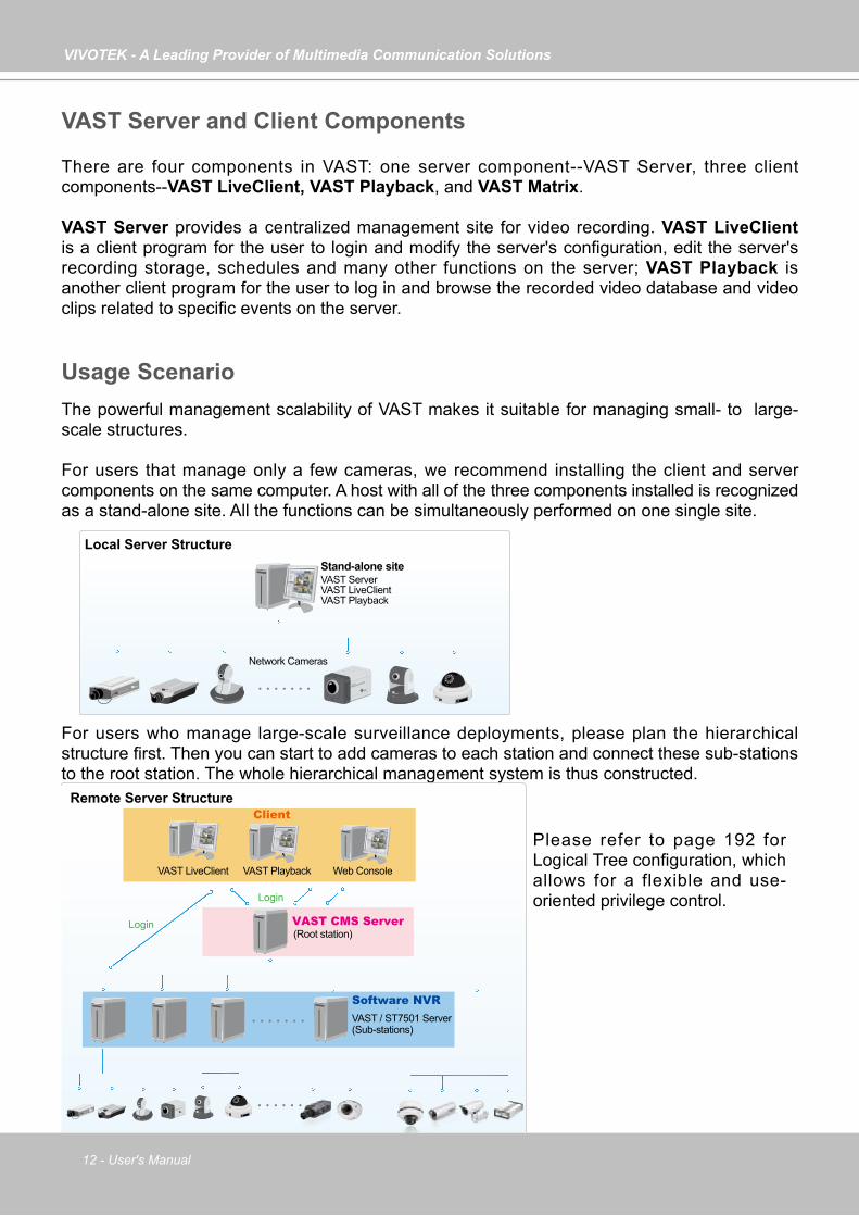
VAST Server and Client Components
There are four components in VAST: one server component--VAST Server, three client components--VAST LiveClient, VAST Playback, and VAST Matrix.
VAST Server provides a centralized management site for video recording. VAST LiveClient is a client program for the user to login and modify the server's configuration, edit the server's recording storage, schedules and many other functions on the server; VAST Playback is another client program for the user to log in and browse the recorded video database and video clips related to specific events on the server.
Usage ScenarioThe powerful management scalability of VAST makes it suitable for managing small- to large-scale structures.
For users that manage only a few cameras, we recommend installing the client and server components on the same computer. A host with all of the three components installed is recognized as a stand-alone site. All the functions can be simultaneously performed on one single site.
For users who manage large-scale surveillance deployments, please plan the hierarchical structure first. Then you can start to add cameras to each station and connect these sub-stations to the root station. The whole hierarchical management system is thus constructed.
Unlimited No. of Network Cameras , Video Servers...
Router
VAST LiveClient VAST Server
Network Cameras
VAST Playback
Stand-alone site
Remote Server Structure
Local Server Structure
Router
Login
Login
VAST LiveClient VAST Playback
Client
(Root station)VAST CMS Server
VAST / ST7501 Server (Sub-stations)
Software NVR
Web Console
Please refer to page 192 for Logical Tree configuration, which allows for a flexible and use-oriented privilege control.
VIVOTEK - A Leading Provider of Multimedia Communication Solutions
User's Manual - 13
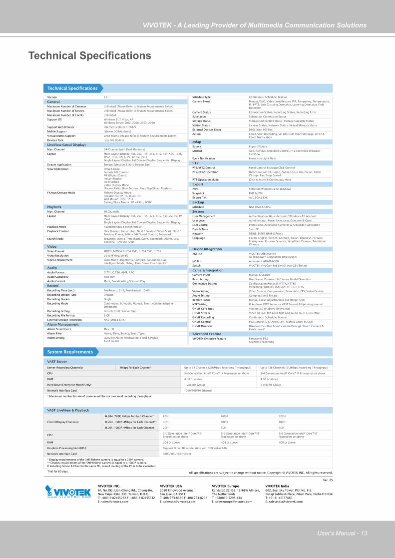
Technical Specifications
Version 1.11
GeneralMaximum Number of Cameras Unlimited (Please Refer to System Requirements Below)
Maximum Number of Servers Unlimited (Please Refer to System Requirements Below)
Maximum Number of Clients Unlimited
Support OS Windows 8, 7, Vista, XPWindows Server 2012, 2008, 2003, 2000
Support Web Browser Internet Explorer 11/10/9
Mobile Support iViewer (iOS/Android)
Virtual Matrix Support VAST Matrix (Please Refer to System Requirements Below)
Devices Pack .vdp File Update
LiveView (Local Display)Max. Channel 64-Channel (with Dual Monitors)
Layout Multi Layout Display: 1x1, 2x2, 1+5, 3x3, 1+12, 4x4, 5x5, 1+31, 1P+2, 1P+6, 1P+8, 2V, 3V, 4V, 2V+3Single Layout Display, Full Screen Display, Sequential Display
Stream Application Stream Selection & Auto Stream Size
View Application Drag & DropRemote I/O ControlPiP (Digital Zoom)Instant ReplayDe-interlaceVideo Display Mode (Aspect Ratio, Hide Borders, Keep Top/Down Borders)
Fisheye Dewarp Mode Fisheye Display Mode: Regular: 1O, 1P, 1R, 1O3R, 4R Wall Mount: 1P2R, 1P3R Ceiling/Floor Mount: 2P, 4R Pro, 1O8R
PlaybackMax. Channel 16 Channels
Layout Multi Layout Display: 1x1, 2x2, 1+5, 3x3, 1+12, 4x4, 2V, 3V, 4V, 2V+3Single Layout Display, Full Screen Display, Sequential Display
Playback Mode Asynchronous & Synchronous
Playback Control Play, Rewind, Pause, Stop, Next / Previous Video Start, Next / Previous Frame, 1/8X ~ 64X Speed Control, Bookmark
Search Mode Browsing, Date & Time (Fast), Event, Bookmark, Alarm, Log, Timeline, Timeline Scale
VideoVideo Format MJPEG, MPEG4, H.264 AVC, H.264 SVC, H.265
Video Resolution Up to 9 Megapixels
Video Enhancement Basic Mode: Brightness, Contrast, Saturation, HueIntelligent Mode: Defog, Rain, Snow, Fire / Smoke
AudioAudio Format G.711, G.726, AMR, AAC
Audio Capability Two Way
Audio Control Mute, Broadcasting & Sound Play
RecordRecording Time (sec.) Pre-Record: 3-15, Post-Record: 10-60
Recording Stream Type Unicast
Recording Stream Single
Recording Mode Continuous, Schedule, Manual, Event, Activity Adaptive Streaming
Recording Setting Recycle (Unit: Size or Day)
Recording File Format 3 GP
External Storage Recording NAS (SMB & CIFS)
Alarm ManagementAlarm Period (sec.) Max. 30
Alarm Filter Name, Time, Source, Event Type
Alarm Setting LiveView Alarm Notification: Fixed & PopupAlert Sound
VAST Server
Server (Recording Channels) 4Mbps for Each Channel* Up to 64 Channels (256Mbps Recording Throughput) Up to 128 Channels (512Mbps Recording Throughput)
CPU 3rd Generation Intel® Core™ i5 Processors or above 3rd Generation Intel® Core™ i7 Processors or above
RAM 4 GB or above 4 GB or above
Hard Drive (Enterprise Model Only) 1 Volume Group 2 Volume Group
Network Interface Card 1000/100/10 Ethernet
* Maximum number bitrate of cameras will be not over total recording throughput.
VAST LiveView & Playback
Client (Display Channels)
H.264, 720P, 4Mbps for Each Channel* 8CH 16CH 32CH
H.264, 1080P, 4Mbps for Each Channel** 4CH 10CH 18CH
H.265, 1080P, 4Mbps for Each Channel 2CH 5CH 9CH
CPU3rd Generation Intel® Core™ i3 Processors or above
3rd Generation Intel® Core™ i5 Processors or above
3rd Generation Intel® Core™ i7 Processors or above
RAM 2GB or above 4GB or above 4GB or above
Graphics Processing Unit (GPU) Support Direct3D acceleration with 1GB Video RAM
Network Interface Card 1000/100/10 Ethernet
* Display requirements of the 3MP fisheye camera is equal to a 720P camera.** Display requirements of the 5MP fisheye camera is equal to a 1080P camera.If installing Server & Client in the same PC, overall loading of the PC is to be evaluated.
Technical Specifications
System Requirements
Schedule Type Continuous, Schedule, Manual
Camera Event Motion, DI/O, Video Lost/Restore, PIR, Tampering, Temperature, IR, PPTZ, Line Crossing Detection, Loitering Detection, Field Detection
Camera Status Connection Status, Recording Status, Recording Error
Substation Substation Connection Status
Storage Status Storage Connection Status, Storage Capacity Status
Station Status License Status, Network Status, Virtual Memory Status
External Devices Event DI/O (With I/O Box)
Action Email, Start Recording, Set DO, GSM Short Message, HTTP & Client Notification
eMapSource Import Picture
Marked Add, Remove, Direction Control, PTZ Control & Indicator LiveView
Event Notification Event Icon Light Flash
PTZPTZ/ePTZ Control Panel Control & Mouse Click Control
PTZ/ePTZ Operation Direction Control, Home, Zoom, Focus, Iris, Preset, Patrol (Group), Pan, Stop, Speed
PTZ Operation Mode Click to Move & Continuous Move
ExportPrint Selection Windows & All Windows
Snapshot BMP & JPEG
Export file AVI, 3GP & EXE
BackupSchedule NAS (SMB & CIFS)
SystemUser Management Authentication: Basic Account / Windows AD Account
User Level Administrator, Power User, User, Operator & Guest
User Control Permission, Accessible Cameras & Accessible Substation
Date & Time Sync PC
Network DDNS, SMTP, UPnP & Proxy
Language Czech, English, French, German, Italian, Japanese, Persian, Portuguese, Russian, Spanish, Simplified Chinese, Traditional Chinese
Device IntegrationJoystick VIVOTEK USB Joystick
All Windows® Compatible USB Joystick
I/O Box Advantech ADAM-6000
Switch VIVOTEK VivoCam PoE Switch (AW-GEV Series)
Camera IntegrationCamera Insert Manual & Search
Basic Setting User Name, Password & Camera Model Detection
Connection Setting Configuration Protocol: HTTP, HTTPSStreaming Protocol: TCP, UDP, HTTP, HTTPS
Video Setting Video Stream, Compression, Resolution, FPS, Video Quality
Audio Setting Compression & Bitrate
Remote Focus Manual Focus Adjustment & Full Range Scan
NTP Setting IP Address (NTP Server or VAST Server) & Updating Interval
ONVIF Core Spec Version 2.2 or above (By Project)
ONVIF Stream Video (H.264, MPEG4 & MJPEG) & Audio (G.711, One Way)
ONVIF Recording Continuous, Schedule, Manual
ONVIF Control PTZ Control (Up, Down, Left, Right & Zoom In/Out)
ONVIF Discover Discover the other brand camera through "Insert Camera & Batch Insert"
Advanced FeatureVIVOTEK Exclusive Feature Panoramic PTZ
Seamless Recording
6F, No.192, Lien-Cheng Rd., Chung-Ho, New Taipei City, 235, Taiwan, R.O.C. T: +886-2-82455282 F: +886-2-82455532 E: [email protected]
VIVOTEK INC.2050 Ringwood Avenue, San Jose, CA 95131 T: 408-773-8686 F: 408-773-8298 E: [email protected]
VIVOTEK USA
Ver. 25
All specifications are subject to change without notice. Copyright © VIVOTEK INC. All rights reserved.
Randstad 22-133, 1316BW Almere, The NetherlandsT: +31(0)36-5298-434E: [email protected]
VIVOTEK Europe602, Best sky Tower, Plot No. F-5, Netaji Subhash Place, Pitam Pura, Delhi-110 034T: +91-11-45137465E: [email protected]
VIVOTEK India
Trial for 60 days.

VIVOTEK - A Leading Provider of Multimedia Communication Solutions
14 - User's Manual
VAST Server Functionality
Centralized management site for all the logged in clients Maintain the configuration of the hierarchical management list Hundreds of video recording channels Store recorded data onto multiple networked or local hard disks Live video for the local/remote LiveClient users Retrieval of recorded video for the local/remote Playback users Zero latency database recovery
LiveClient is the management interface to your VAST server. The server-related settings are made via the VAST LiveClient utility. The convenient and intuitive user interface on VAST LiveClient provides access to camera, live monitoring, and recording configurations.
VIVOTEK - A Leading Provider of Multimedia Communication Solutions
User's Manual - 15
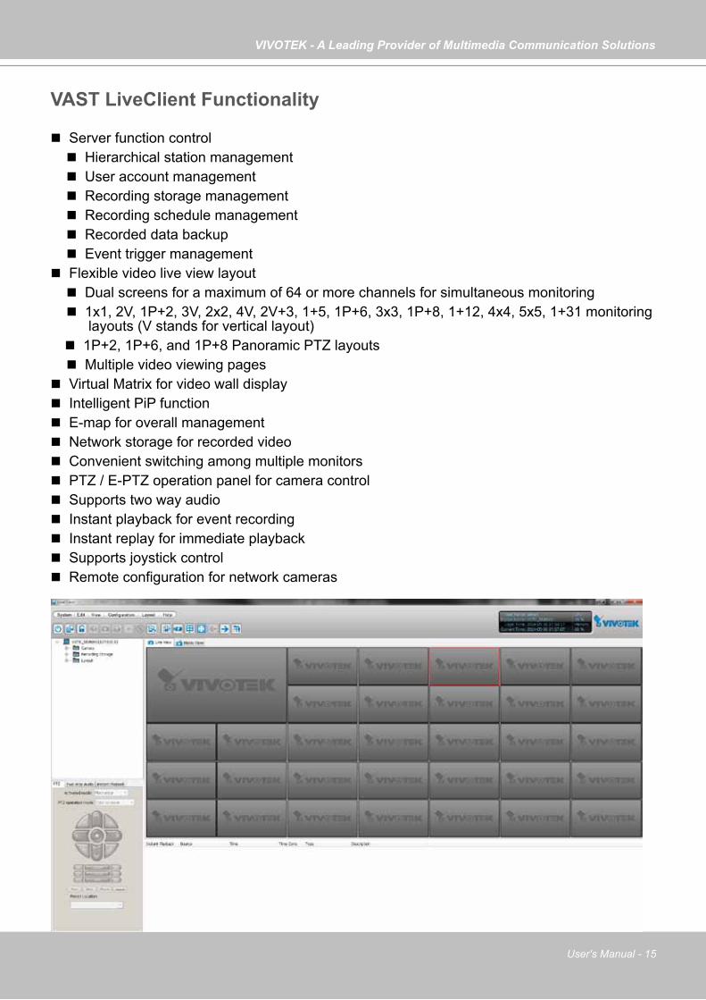
VAST LiveClient Functionality
Server function control Hierarchical station management User account management Recording storage management Recording schedule management Recorded data backup Event trigger management Flexible video live view layout Dual screens for a maximum of 64 or more channels for simultaneous monitoring 1x1, 2V, 1P+2, 3V, 2x2, 4V, 2V+3, 1+5, 1P+6, 3x3, 1P+8, 1+12, 4x4, 5x5, 1+31 monitoring
layouts (V stands for vertical layout) 1P+2, 1P+6, and 1P+8 Panoramic PTZ layouts Multiple video viewing pages Virtual Matrix for video wall display Intelligent PiP function E-map for overall management Network storage for recorded video Convenient switching among multiple monitors PTZ / E-PTZ operation panel for camera control Supports two way audio Instant playback for event recording Instant replay for immediate playback Supports joystick control Remote configuration for network cameras
VIVOTEK - A Leading Provider of Multimedia Communication Solutions
16 - User's Manual
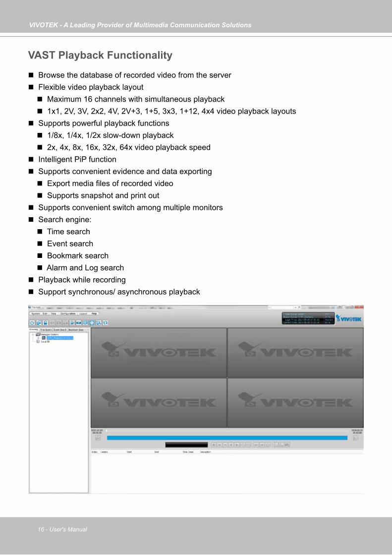
VAST Playback Functionality
Browse the database of recorded video from the server Flexible video playback layout Maximum 16 channels with simultaneous playback 1x1, 2V, 3V, 2x2, 4V, 2V+3, 1+5, 3x3, 1+12, 4x4 video playback layouts Supports powerful playback functions 1/8x, 1/4x, 1/2x slow-down playback 2x, 4x, 8x, 16x, 32x, 64x video playback speed Intelligent PiP function Supports convenient evidence and data exporting Export media files of recorded video Supports snapshot and print out Supports convenient switch among multiple monitors Search engine: Time search Event search Bookmark search Alarm and Log search Playback while recording Support synchronous/ asynchronous playback
VIVOTEK - A Leading Provider of Multimedia Communication Solutions
User's Manual - 17
Minimum System RequirementsBefore installing the VAST software, please make sure your system meets the following recommended minimum system requirements.If you would like to install ST7501 Server only, please follow the requirements as below:
ServerOperating System Windows Server 2000, 2003, 2008, 2012 / Windows XP Professional, Windows
7, Windows 8 Recording Channels (4Mbps per CH) up to 64 CH (256Mbps throughput) Up to 128CH (512Mbps throughput)
CPU 3rd Generation Intel® Core™ i5 Processors or above
3rd Generation Intel® Core™ i7 Processors or above
RAM 4GB or above - 64CH; 8GB or above - 128CHNetwork Interface Card Ethernet, 1 Gbit recommendedGraphics Adapter DirectX 9 compatible 1GB graphics card
Hard Disk Type Single recording group w/ one HDD Two recording group w/ two HDDs* SATA, SCSI, SAS (7200 rpm or faster) in NTFS format
LiveClient and Playback
Operating System Windows Server 2000, 2003, 2008, 2012 / Windows XP Professional, Windows Vista, Windows 7, Windows 8
Clients (Display Channels)
720P,4Mbps, H.264* 8CH 16CH 32CH
1080P,4Mbps, H.264** 4CH 10CH 18 CH
1080P,4Mbps, H.265 2CH 5CH 9CH
CPU 3rd Generation Intel® Core™ i3 Processors
3rd Generation Intel® Core™ i5 Processors
3rd Generation Intel® Core™ i7 Processors
RAM 2 GB or above 4GB or above 4GB or aboveNetwork Interface Card Ethernet, 1Gbit recommended
Graphics Adapter DirectX 9 compatible 1GB graphics card
* Each recording group can receive recordings for 60 channels.
If you would like to install both the server and client programs, please follow the requirements as below:
* Display requirements of the 3MP fisheye camera is equal to a 720P camera.** Display requirements of the 5MP fisheye camera is equal to a 1080P camera.
If installing Server and Client on the same PC, the overall loading on the PC is to be evaluated.
VIVOTEK - A Leading Provider of Multimedia Communication Solutions
18 - User's Manual
Only users with Administrator privileges can install or use VAST on a Windows Vista system. The required hard disk space will depend on the video settings, the number of network cameras and recording
group settings. Please add more hard disks if you want to extend the system. Below are approximate numbers for a week-long recording. The actual storage space required also depends on
imaging parameters, e.g., a complex retail environment that involves many moving objects requires more pixel data to be transmitted over network than a simple environment such as a parking lot.
32-CH, VGA, about 1 week recording: 750 GB 64-CH, VGA, about 1 week recording: 1TB x 2 32-CH, 2-megapixel, about 1 week recording: 2TB x 2 64-CH, 2-megapixel, about 1 week recording: 2TB x 4
VIVOTEK - A Leading Provider of Multimedia Communication Solutions
User's Manual - 19
Dongle license users
Scenario Need Action
Need more CHs 1. Help > License > export license.
2. Send license file to VIVOTEK to purchase more dongle license.
New users preferringmore than 32 CHs
Need more than32 CHs.
1. Install the 256 CH trial VAST.
3. Send request file to VIVOTEK to purchase software license.
2. Help > License > Generate licenseupdate request.
New users fine with32 CHs
Fine with less than32 CHs.
1. Install the 32 CH free VAST.
VAST Software License
To activate the software, refer to the flow chart below:
The VAST software provides 32 free channels. Since revision 1.11, the VAST software is activated using a software license instead of the original hardware dongle.
For users running the previous dongle version, there is no need to upgrade their original license. If they need the license for more channels, They can export their license file, and purchase more dongle licenses.
For users who require more than 32 channels, they can install the 256 channel trial version first, and go to Help > License page, and click on Generate License Update Request. Send the request back to VIVOTEK to purchase more channel licenses.
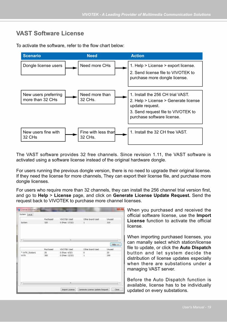
When you purchased and received the official software license, use the Import License function to activate the official license.
When importing purchased licenses, you can manally select which station/license file to update, or click the Auto Dispatch but ton and le t system dec ide the distribution of license updates especially when there are substations under a managing VAST server.
Before the Auto Dispatch function is available, license has to be individually updated on every substations.
VIVOTEK - A Leading Provider of Multimedia Communication Solutions
20 - User's Manual
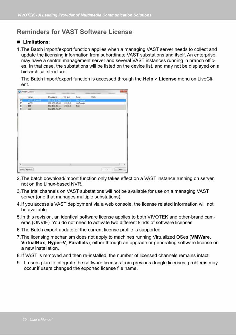
Limitations:1. The Batch import/export function applies when a managing VAST server needs to collect and
update the licensing information from subordinate VAST substations and itself. An enterprise may have a central management server and several VAST instances running in branch offic-es. In that case, the substations will be listed on the device list, and may not be displayed on a hierarchical structure.
The Batch import/export function is accessed through the Help > License menu on LiveCli-ent.
Reminders for VAST Software License
2. The batch download/import function only takes effect on a VAST instance running on server, not on the Linux-based NVR.
3. The trial channels on VAST substations will not be available for use on a managing VAST server (one that manages multiple substations).
4. If you access a VAST deployment via a web console, the license related information will not be available.
5. In this revision, an identical software license applies to both VIVOTEK and other-brand cam-eras (ONVIF). You do not need to activate two different kinds of software licenses.
6. The Batch export update of the current license profile is supported.7. The licensing mechanism does not apply to machines running Virtualized OSes (VMWare,
VirtualBox, Hyper-V, Parallels), either through an upgrade or generating software license on a new installation.
8. If VAST is removed and then re-installed, the number of licensed channels remains intact. 9. If users plan to integrate the software licenses from previous dongle licenses, problems may
occur if users changed the exported license file name.
VIVOTEK - A Leading Provider of Multimedia Communication Solutions
User's Manual - 21
10. The VAST rev. 1.11 supports 32 free channels, and trial licenses for up to 256 channels. Note that the unused trial licenses in a VAST substation will not be available for a managing VAST server. The 32 free licenses will be available for a stand-alone VAST server only.
11. The software license verifies its availability on a machine by checking the computer’s main components, e.g., GPU or memory. If a VAST server has several of its main components re-placed, the software license may become invalid. Note that users can only change 2 compo-nents on a substation (server components - CPU/Memory/Graphics card/Network card/Main board).
12. For an older VAST installation containing a VAST substation licensed through the dongle, the 32 free channels will be automatically added to the total number of licensed channels. One substation comes with 32 free channels. The added number of licensed channels will be-come available for the managing VAST server.
VIVOTEK - A Leading Provider of Multimedia Communication Solutions
22 - User's Manual
VAST InstallationInstalling the VAST Software
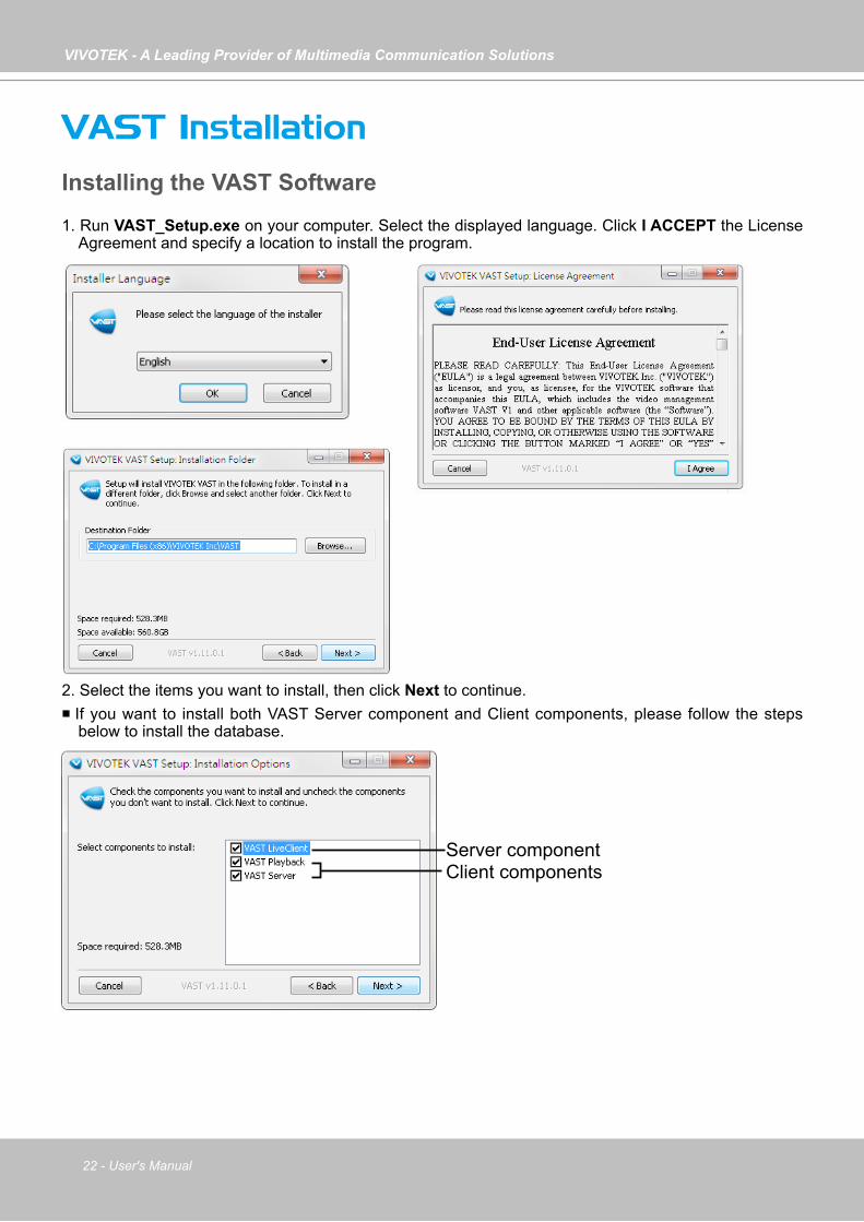
1. Run VAST_Setup.exe on your computer. Select the displayed language. Click I ACCEPT the License Agreement and specify a location to install the program.
Server componentClient components
2. Select the items you want to install, then click Next to continue. If you want to install both VAST Server component and Client components, please follow the steps
below to install the database.
VIVOTEK - A Leading Provider of Multimedia Communication Solutions
User's Manual - 23
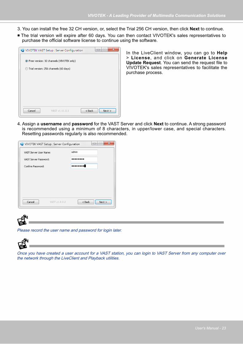
4. Assign a username and password for the VAST Server and click Next to continue. A strong password is recommended using a minimum of 8 characters, in upper/lower case, and special characters. Resetting passwords regularly is also recommended.
3. You can install the free 32 CH version, or, select the Trial 256 CH version, then click Next to continue. The trial version will expire after 60 days. You can then contact VIVOTEK's sales representatives to
purchase the official software license to continue using the software.
Please record the user name and password for login later.
In the LiveClient window, you can go to Help > License, and click on Generate License Update Request. You can send the request file to VIVOTEK's sales representatives to facilitate the purchase process.
Once you have created a user account for a VAST station, you can login to VAST Server from any computer over the network through the LiveClient and Playback utilities.
VIVOTEK - A Leading Provider of Multimedia Communication Solutions
24 - User's Manual
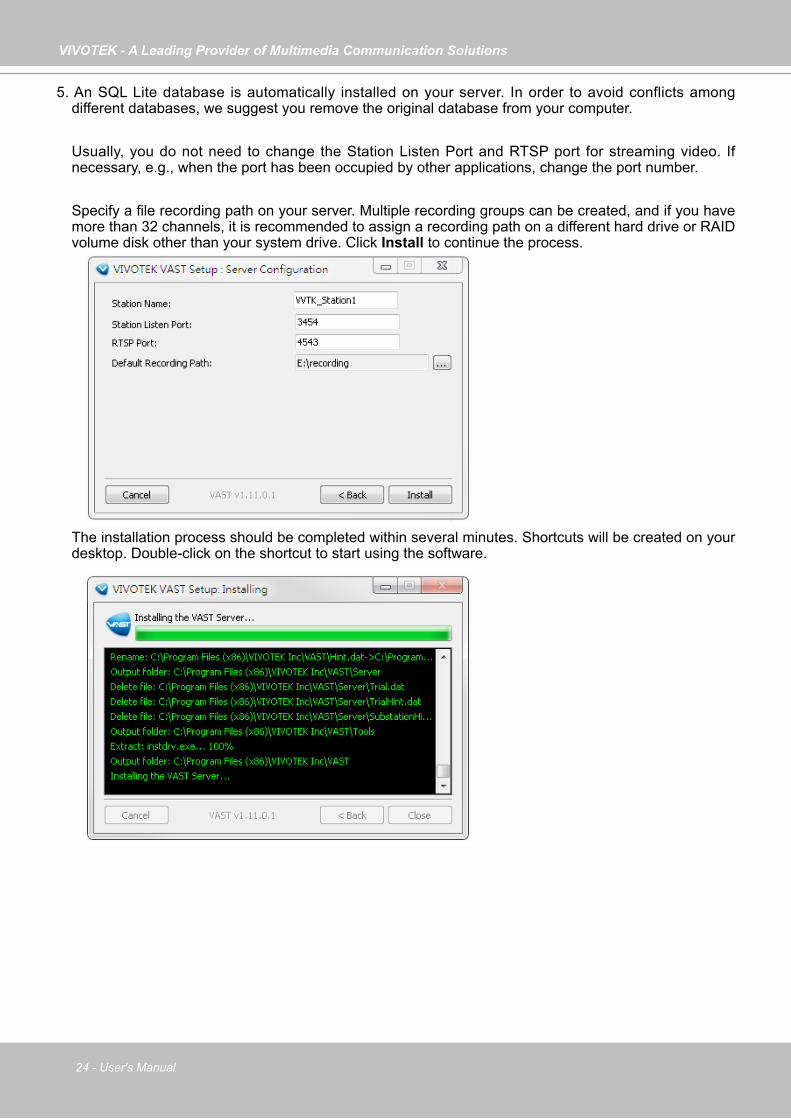
5. An SQL Lite database is automatically installed on your server. In order to avoid conflicts among different databases, we suggest you remove the original database from your computer.
Usually, you do not need to change the Station Listen Port and RTSP port for streaming video. If
necessary, e.g., when the port has been occupied by other applications, change the port number.
Specify a file recording path on your server. Multiple recording groups can be created, and if you have more than 32 channels, it is recommended to assign a recording path on a different hard drive or RAID volume disk other than your system drive. Click Install to continue the process.
The installation process should be completed within several minutes. Shortcuts will be created on your desktop. Double-click on the shortcut to start using the software.
VIVOTEK - A Leading Provider of Multimedia Communication Solutions
User's Manual - 25
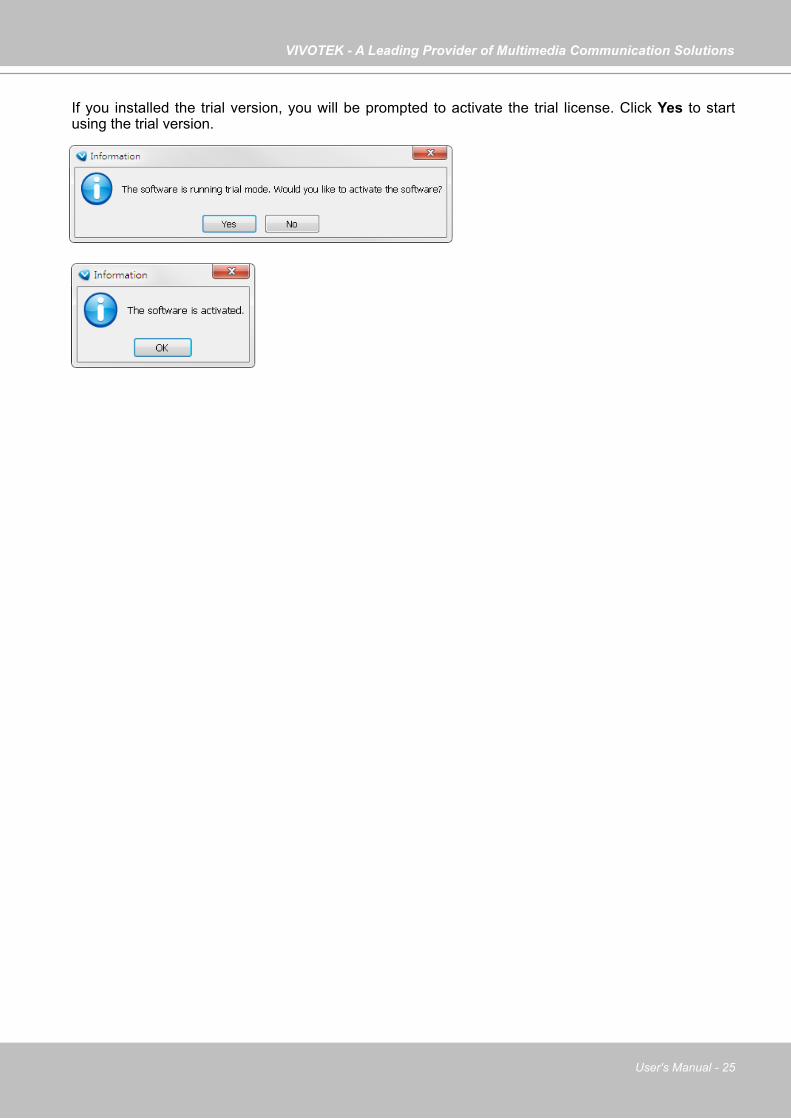
If you installed the trial version, you will be prompted to activate the trial license. Click Yes to start using the trial version.
VIVOTEK - A Leading Provider of Multimedia Communication Solutions
26 - User's Manual
VAST ServerActivating the VAST Server
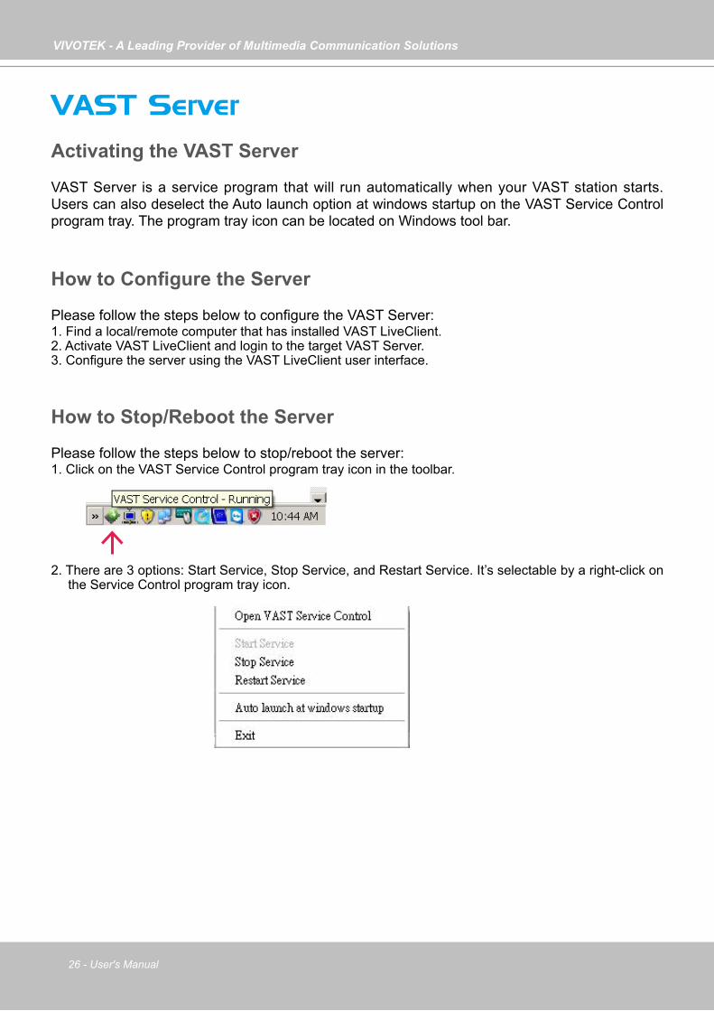
VAST Server is a service program that will run automatically when your VAST station starts. Users can also deselect the Auto launch option at windows startup on the VAST Service Control program tray. The program tray icon can be located on Windows tool bar.
How to Configure the Server
Please follow the steps below to configure the VAST Server:1. Find a local/remote computer that has installed VAST LiveClient.2. Activate VAST LiveClient and login to the target VAST Server.3. Configure the server using the VAST LiveClient user interface.
How to Stop/Reboot the Server
Please follow the steps below to stop/reboot the server:1. Click on the VAST Service Control program tray icon in the toolbar.
2. There are 3 options: Start Service, Stop Service, and Restart Service. It’s selectable by a right-click on the Service Control program tray icon.
VIVOTEK - A Leading Provider of Multimedia Communication Solutions
User's Manual - 27
VAST LiveClient ConfigurationActivating the VAST LiveClient and Logging in to a VAST Server
VAST LiveClient allows you to monitor live video from cameras managed by the VAST Server; it is also the main user interface for server function control.
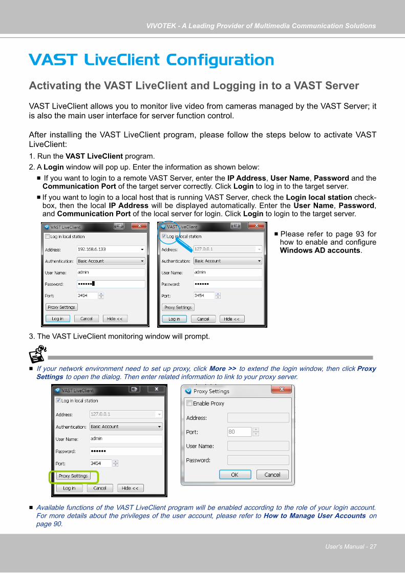
After installing the VAST LiveClient program, please follow the steps below to activate VAST LiveClient:1. Run the VAST LiveClient program.2. A Login window will pop up. Enter the information as shown below: If you want to login to a remote VAST Server, enter the IP Address, User Name, Password and the
Communication Port of the target server correctly. Click Login to log in to the target server. If you want to login to a local host that is running VAST Server, check the Login local station check-
box, then the local IP Address will be displayed automatically. Enter the User Name, Password, and Communication Port of the local server for login. Click Login to login to the target server.
3. The VAST LiveClient monitoring window will prompt.
If your network environment need to set up proxy, click More >> to extend the login window, then click Proxy Settings to open the dialog. Then enter related information to link to your proxy server.
Available functions of the VAST LiveClient program will be enabled according to the role of your login account. For more details about the privileges of the user account, please refer to How to Manage User Accounts on page 90.
Please refer to page 93 for how to enable and configure Windows AD accounts.

VIVOTEK - A Leading Provider of Multimedia Communication Solutions
28 - User's Manual
VAST LiveClient User Interface
Menu Bar
E
CB
G
A
D
Menu Item Drop-down Options
System Lock / Enable Click On Image (Disable Click On Image) / Language / Second View / E-map / Launch Playback / Logout / Exit
Edit Manually Begin Recording (Stop Manual Recording) / Snapshot / Print / Record to EXE (3GP, AVI) / Snapshot Zoomed Image / Print Zoomed Image / Find
View Logical Tree view/ Device Tree view/ PTZ Panel / Two Way Audio Panel / Instant Playback Panel / Alarm Window / Full Screen / Minimize / Matrix View
Configuration
Camera Management (Insert Camera / Update Camera / Delete Cameras / Batch Insert Cameras / Camera Configuration) / Station Management / Logical Tree View management / IO Box Management / User Management / Association Management / Alarm Management / Virtual Matrix Management (Matrix Management / Matrix View Settings) / Station Settings (General Settings / Network Settings / Recording Storage Settings / Recording Schedule Settings / Scheduled Backup Settings / Server Settings / Relay Settings) / Client Settings (Snapshot Settings / Recording Settings / View Settings / General Settings / Joystick Settings / Proxy Settings / PiP Settings) / Video Enhancement (Basic Image Adjustment / Defog)
Layout Start Rotating (Stop Rotating) / Save to / Delete / Choose
Help About / License
A. Menu bar B. Quick access bar C. Hierarchical management tree D. Camera control panel (PTZ / Two way audio / Instant Playback control panel)E. Live view window F. Matrix view window G. Status panel H. Alarm window
H
F
VIVOTEK - A Leading Provider of Multimedia Communication Solutions
User's Manual - 29
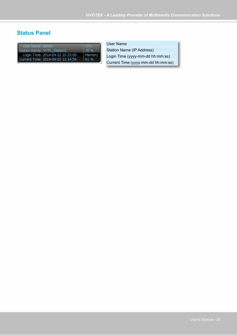
Status Panel
User NameStation Name (IP Address)Login Time (yyyy-mm-dd hh:mm:ss)Current Time (yyyy-mm-dd hh:mm:ss)
VIVOTEK - A Leading Provider of Multimedia Communication Solutions
30 - User's Manual
Help Panel
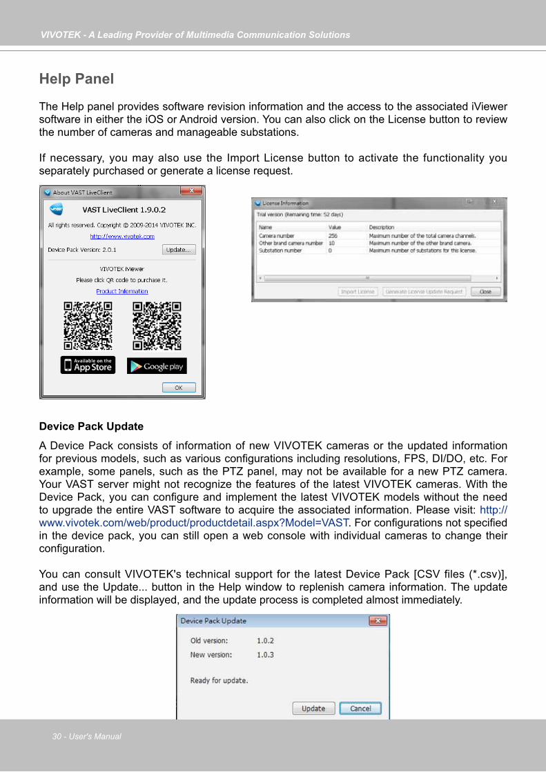
The Help panel provides software revision information and the access to the associated iViewer software in either the iOS or Android version. You can also click on the License button to review the number of cameras and manageable substations.
If necessary, you may also use the Import License button to activate the functionality you separately purchased or generate a license request.
Device Pack Update
A Device Pack consists of information of new VIVOTEK cameras or the updated information for previous models, such as various configurations including resolutions, FPS, DI/DO, etc. For example, some panels, such as the PTZ panel, may not be available for a new PTZ camera. Your VAST server might not recognize the features of the latest VIVOTEK cameras. With the Device Pack, you can configure and implement the latest VIVOTEK models without the need to upgrade the entire VAST software to acquire the associated information. Please visit: http://www.vivotek.com/web/product/productdetail.aspx?Model=VAST. For configurations not specified in the device pack, you can still open a web console with individual cameras to change their configuration.
You can consult VIVOTEK's technical support for the latest Device Pack [CSV files (*.csv)], and use the Update... button in the Help window to replenish camera information. The update information will be displayed, and the update process is completed almost immediately.
VIVOTEK - A Leading Provider of Multimedia Communication Solutions
User's Manual - 31
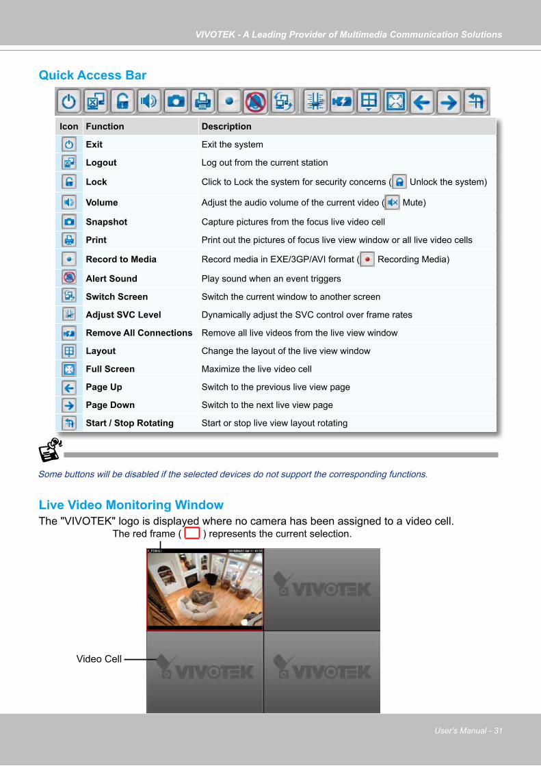
Quick Access Bar
Some buttons will be disabled if the selected devices do not support the corresponding functions.
Live Video Monitoring WindowThe "VIVOTEK" logo is displayed where no camera has been assigned to a video cell.
Icon Function Description
Exit Exit the system
Logout Log out from the current station
Lock Click to Lock the system for security concerns ( Unlock the system)
Volume Adjust the audio volume of the current video ( Mute)
Snapshot Capture pictures from the focus live video cell
Print Print out the pictures of focus live view window or all live video cells
Record to Media Record media in EXE/3GP/AVI format ( Recording Media)
Alert Sound Play sound when an event triggers
Switch Screen Switch the current window to another screen
Adjust SVC Level Dynamically adjust the SVC control over frame rates
Remove All Connections Remove all live videos from the live view window
Layout Change the layout of the live view window
Full Screen Maximize the live video cell
Page Up Switch to the previous live view page
Page Down Switch to the next live view page
Start / Stop Rotating Start or stop live view layout rotating
The red frame ( ) represents the current selection.
Video Cell

VIVOTEK - A Leading Provider of Multimedia Communication Solutions
32 - User's Manual
Hierarchical Management Tree
Root Station Name (IP address)
Connected devices listed under the root stationCamera name (IP Address)
Connected devices that have been assigned to the default recording storage
Layout list
Icon Description
A station (The host that’s installed with VAST Server)
A station (The host that’s installed with ST7501 Server)
/ VIVOTEK fixed network camera (or ONVIF cameras)Red dot signifies that the camera is recording.
/ VIVOTEK PTZ network cameraRed dot signifies that the camera is recording.
/ VIVOTEK dome network cameraRed dot signifies that the camera is recording.
/ VIVOTEK fisheye network cameraRed dot indicates that the camera is recording.
/ VIVOTEK video serverRed dot signifies that the video server is recording.
/ Digital input on / off
/ Digital output on / off
A layout of the live monitoring window
A station that’s not able to be connected currently.
A device that’s not able to be connected currently.
Sub-station Name (IP address)
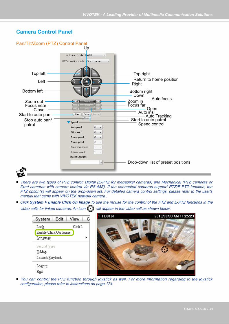
VIVOTEK - A Leading Provider of Multimedia Communication Solutions
User's Manual - 33
Camera Control Panel
Pan/Tilt/Zoom (PTZ) Control Panel
There are two types of PTZ control: Digital (E-PTZ for megapixel cameras) and Mechanical (PTZ cameras or fixed cameras with camera control via RS-485). If the connected cameras support PTZ/E-PTZ function, the PTZ option(s) will appear on the drop-down list. For detailed camera control settings, please refer to the user's manual that came with VIVOTEK network camera .
Click System > Enable Click On Image to use the mouse for the control of the PTZ and E-PTZ functions in the video cells for linked cameras. An icon will appear in the video cell as shown below.
You can control the PTZ function through joystick as well. For more information regarding to the joystick configuration, please refer to instructions on page 174.
Top left
Left
Bottom left
Focus nearClose
Start to auto pan
Zoom out
Up
Return to home position
Bottom right
Right
Top right
Down
Focus farZoom in
Open
Start to auto patrolStop auto pan/patrol
Drop-down list of preset positions
Auto focus
Auto iris
Speed control
Auto Tracking
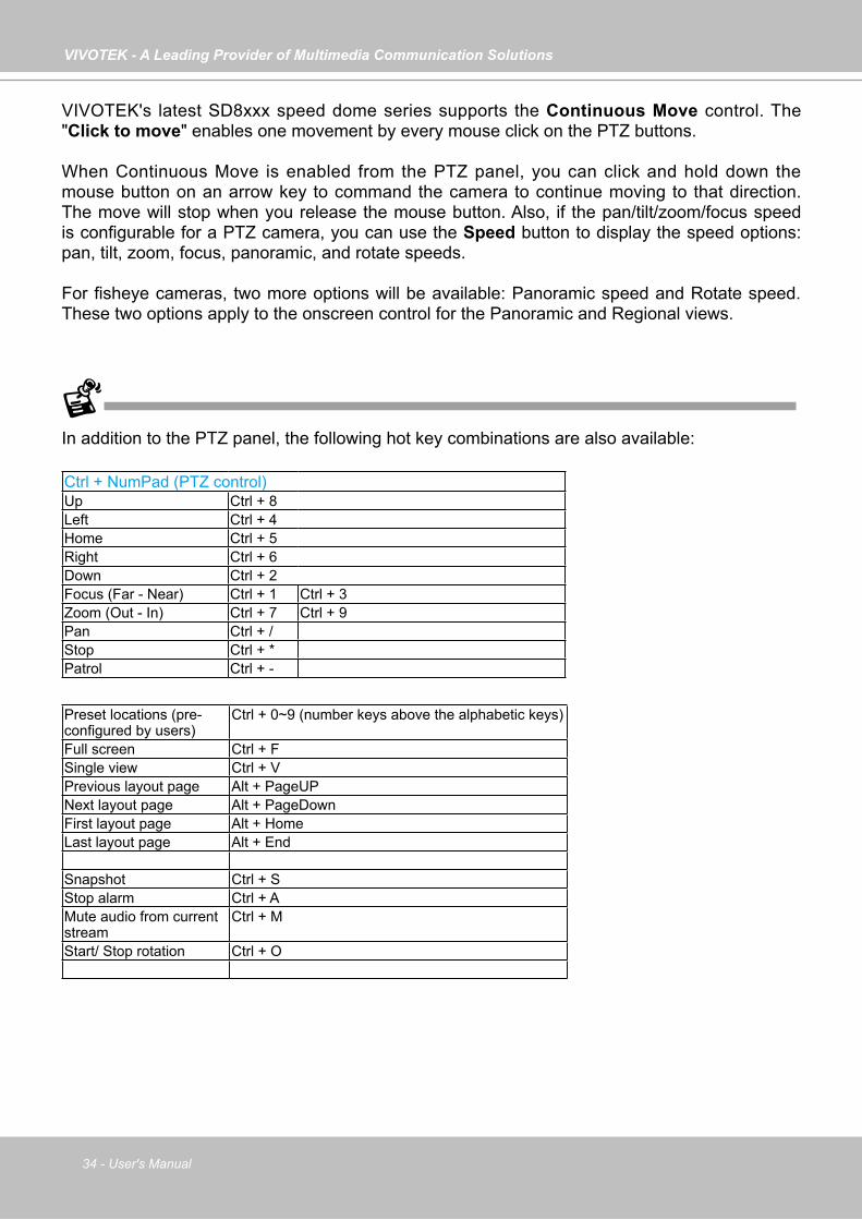
VIVOTEK - A Leading Provider of Multimedia Communication Solutions
34 - User's Manual
In addition to the PTZ panel, the following hot key combinations are also available:
Ctrl + NumPad (PTZ control)Up Ctrl + 8Left Ctrl + 4Home Ctrl + 5Right Ctrl + 6Down Ctrl + 2Focus (Far - Near) Ctrl + 1 Ctrl + 3Zoom (Out - In) Ctrl + 7 Ctrl + 9Pan Ctrl + /Stop Ctrl + *Patrol Ctrl + -
Preset locations (pre-configured by users)
Ctrl + 0~9 (number keys above the alphabetic keys)
Full screen Ctrl + FSingle view Ctrl + VPrevious layout page Alt + PageUPNext layout page Alt + PageDownFirst layout page Alt + HomeLast layout page Alt + End
Snapshot Ctrl + SStop alarm Ctrl + AMute audio from current stream
Ctrl + M
Start/ Stop rotation Ctrl + O
VIVOTEK's latest SD8xxx speed dome series supports the Continuous Move control. The "Click to move" enables one movement by every mouse click on the PTZ buttons.
When Continuous Move is enabled from the PTZ panel, you can click and hold down the mouse button on an arrow key to command the camera to continue moving to that direction. The move will stop when you release the mouse button. Also, if the pan/tilt/zoom/focus speed is configurable for a PTZ camera, you can use the Speed button to display the speed options: pan, tilt, zoom, focus, panoramic, and rotate speeds.
For fisheye cameras, two more options will be available: Panoramic speed and Rotate speed. These two options apply to the onscreen control for the Panoramic and Regional views.
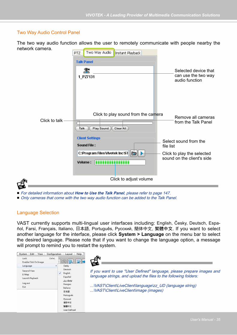
VIVOTEK - A Leading Provider of Multimedia Communication Solutions
User's Manual - 35
Two Way Audio Control Panel
The two way audio function allows the user to remotely communicate with people nearby the network camera.
For detailed information about How to Use the Talk Panel, please refer to page 147. Only cameras that come with the two way audio function can be added to the Talk Panel.
Language Selection
VAST currently supports multi-lingual user interfaces including: English, Česky, Deutsch, Espa-ñol, Farsi, Français, Italiano, 日本語, Português, Русский, 簡体中文, 繁體中文. If you want to select another language for the interface, please click System > Language on the menu bar to select the desired language. Please note that if you want to change the language option, a message will prompt to remind you to restart the system.
Remove all cameras from the Talk Panel
Click to play sound from the cameraClick to talk
Click to adjust volume
Selected device that can use the two way audio function
Click to play the selected sound on the client's side
If you want to use "User Defined" language, please prepare images and language strings, and upload the files to the following folders:
...\VAST\Client\LiveClient\language\zz_UD (language string)
...\VAST\Client\LiveClient\image (images)
Select sound from the file list
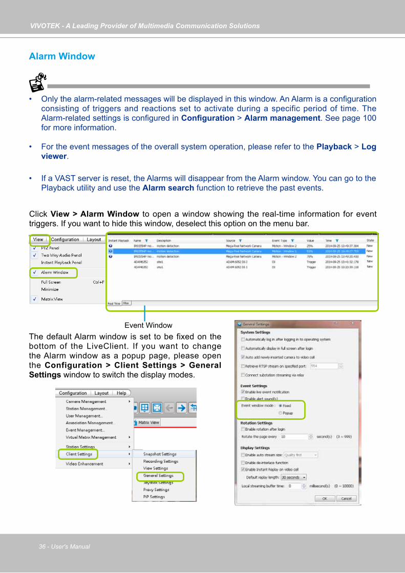
VIVOTEK - A Leading Provider of Multimedia Communication Solutions
36 - User's Manual
Click View > Alarm Window to open a window showing the real-time information for event triggers. If you want to hide this window, deselect this option on the menu bar.
The default Alarm window is set to be fixed on the bottom of the LiveClient. If you want to change the Alarm window as a popup page, please open the Configuration > Client Settings > General Settings window to switch the display modes.
Event Window
Alarm Window
• Only the alarm-related messages will be displayed in this window. An Alarm is a configuration consisting of triggers and reactions set to activate during a specific period of time. The Alarm-related settings is configured in Configuration > Alarm management. See page 100 for more information.
• For the event messages of the overall system operation, please refer to the Playback > Log viewer.
• If a VAST server is reset, the Alarms will disappear from the Alarm window. You can go to the Playback utility and use the Alarm search function to retrieve the past events.
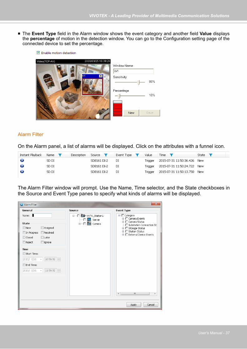
VIVOTEK - A Leading Provider of Multimedia Communication Solutions
User's Manual - 37
Video(TCP-AV)
Alarm Filter
On the Alarm panel, a list of alarms will be displayed. Click on the attributes with a funnel icon.
The Alarm Filter window will prompt. Use the Name, Time selector, and the State checkboxes in the Source and Event Type panes to specify what kinds of alarms will be displayed.
The Event Type field in the Alarm window shows the event category and another field Value displays the percentage of motion in the detection window. You can go to the Configuration setting page of the connected device to set the percentage.

VIVOTEK - A Leading Provider of Multimedia Communication Solutions
38 - User's Manual
Use the Filter tab at the bottom of the Alarm window to display a different sorted result.
For example, you can set up a filter to display the alarms with a name associated with a specific camera, such as "bullet on the corridor." The name of the alarm is configured in Configuration > Alarm management on page 100.
Alarm State
Left-click to select an alarm, and then right-click to display the Update Alarm button.
You can change the alarm state from the pull-down menu. For example, if someone has already been sent to check out the situation, for example, an intruder broke in through a window, you can select the Assigned status. A 1024 bytes decription can be added into the alarm Note for
future reference.
I f an a la rm is p roved as a fa lse a larm, the a larm can be designated as Ignore or Resolved, and so on.
The different alarm states can also be used as the fi ltering conditions in the Alarm filter. Single or multiple states can be selected in the fi l ter. For example, to display the Resolved alarms only, use the Resolved state as the filter.

VIVOTEK - A Leading Provider of Multimedia Communication Solutions
User's Manual - 39
Instant Playback
Check View > Instant Playback to open the window on the panel. The entries listed in the Event panel are the short recordings made from triggered events.
The recorded media that was triggered by an event will be indicated with a playable icon.
You can double-click an event on the list to playback the recorded video. Each event contains a video clip of 20 seconds in length. (The default recording data of an event is 20 seconds. For more information about event recording, please refer to page 120.)
Instant Playback Window with a slide bar, play, pause, and stop function
Deselect this item if you want to hide this window.
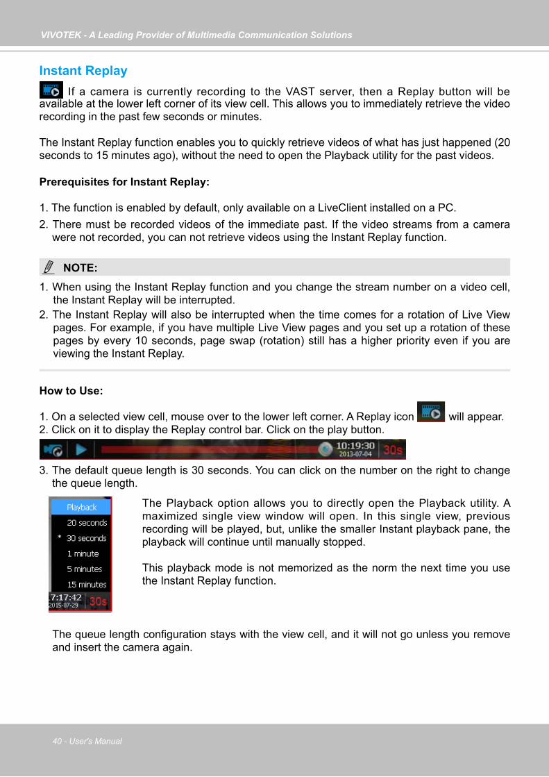
VIVOTEK - A Leading Provider of Multimedia Communication Solutions
40 - User's Manual
Instant Replay If a camera is currently recording to the VAST server, then a Replay button will be
available at the lower left corner of its view cell. This allows you to immediately retrieve the video recording in the past few seconds or minutes.
The Instant Replay function enables you to quickly retrieve videos of what has just happened (20 seconds to 15 minutes ago), without the need to open the Playback utility for the past videos.
Prerequisites for Instant Replay:
1. The function is enabled by default, only available on a LiveClient installed on a PC.2. There must be recorded videos of the immediate past. If the video streams from a camera
were not recorded, you can not retrieve videos using the Instant Replay function.
NOTE:1. When using the Instant Replay function and you change the stream number on a video cell,
the Instant Replay will be interrupted.2. The Instant Replay will also be interrupted when the time comes for a rotation of Live View
pages. For example, if you have multiple Live View pages and you set up a rotation of these pages by every 10 seconds, page swap (rotation) still has a higher priority even if you are viewing the Instant Replay.
How to Use:
1. On a selected view cell, mouse over to the lower left corner. A Replay icon will appear. 2. Click on it to display the Replay control bar. Click on the play button.
3. The default queue length is 30 seconds. You can click on the number on the right to change the queue length.
The Playback option allows you to directly open the Playback utility. A maximized single view window will open. In this single view, previous recording will be played, but, unlike the smaller Instant playback pane, the playback will continue until manually stopped.
This playback mode is not memorized as the norm the next time you use the Instant Replay function.
The queue length configuration stays with the view cell, and it will not go unless you remove and insert the camera again.
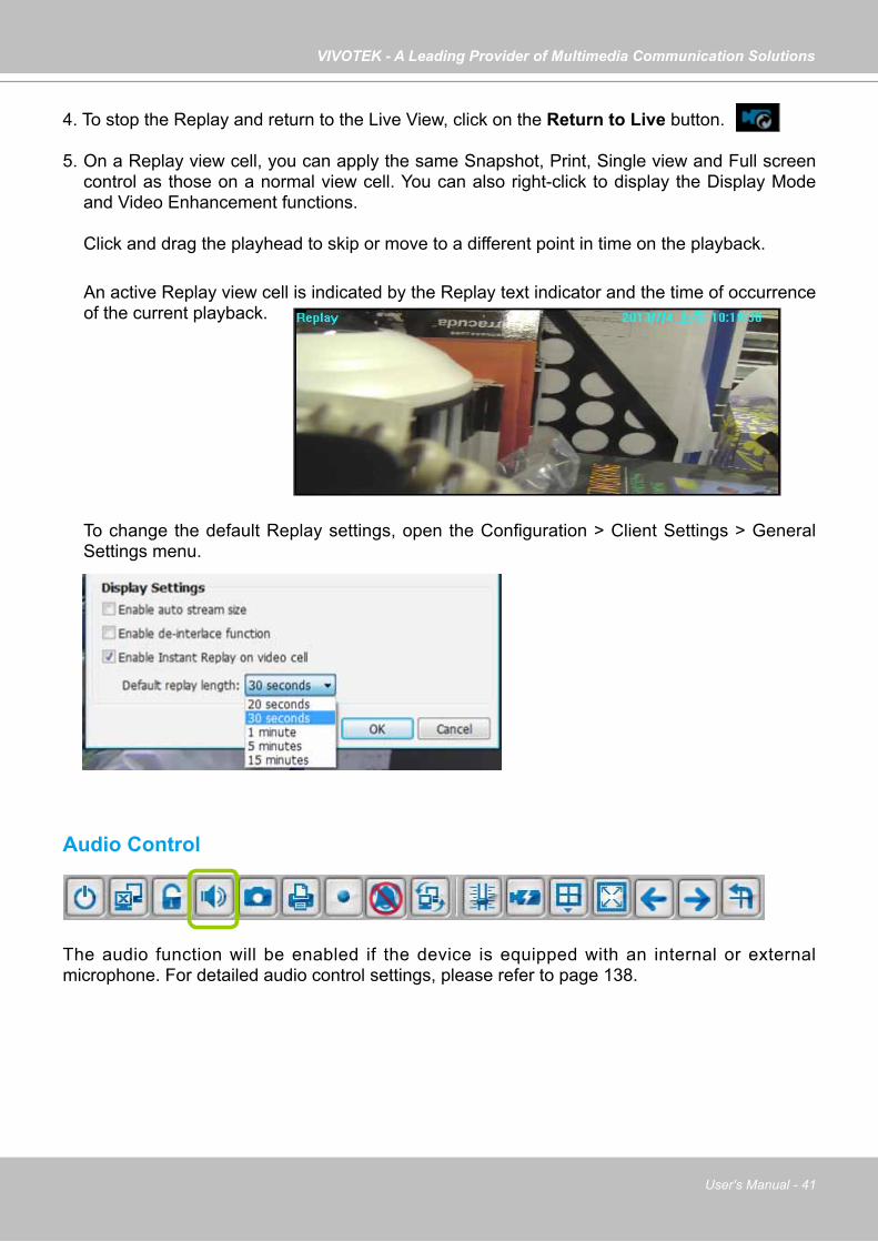
VIVOTEK - A Leading Provider of Multimedia Communication Solutions
User's Manual - 41
Audio Control
The audio function will be enabled if the device is equipped with an internal or external microphone. For detailed audio control settings, please refer to page 138.
An active Replay view cell is indicated by the Replay text indicator and the time of occurrence of the current playback.
To change the default Replay settings, open the Configuration > Client Settings > General Settings menu.
4. To stop the Replay and return to the Live View, click on the Return to Live button. 5. On a Replay view cell, you can apply the same Snapshot, Print, Single view and Full screen
control as those on a normal view cell. You can also right-click to display the Display Mode and Video Enhancement functions.
Click and drag the playhead to skip or move to a different point in time on the playback.
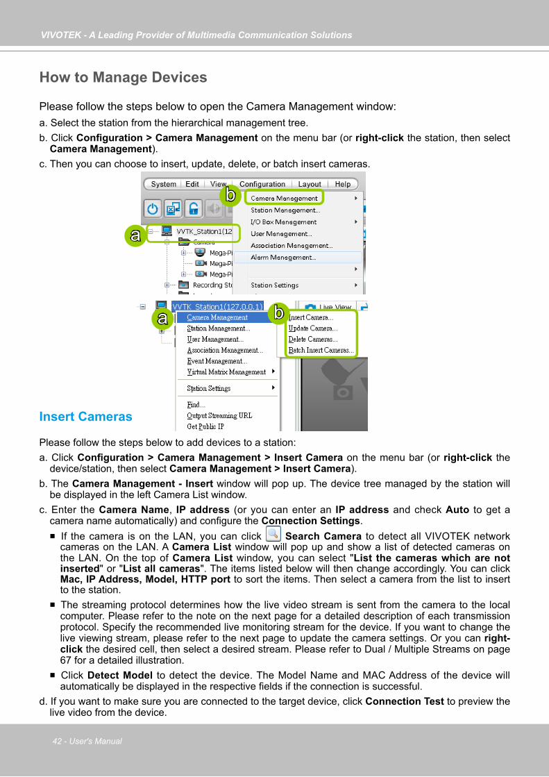
VIVOTEK - A Leading Provider of Multimedia Communication Solutions
42 - User's Manual
How to Manage Devices
Please follow the steps below to open the Camera Management window:a. Select the station from the hierarchical management tree.b. Click Configuration > Camera Management on the menu bar (or right-click the station, then select
Camera Management).c. Then you can choose to insert, update, delete, or batch insert cameras.
Insert Cameras
Please follow the steps below to add devices to a station:a. Click Configuration > Camera Management > Insert Camera on the menu bar (or right-click the
device/station, then select Camera Management > Insert Camera).b. The Camera Management - Insert window will pop up. The device tree managed by the station will
be displayed in the left Camera List window.c. Enter the Camera Name, IP address (or you can enter an IP address and check Auto to get a
camera name automatically) and configure the Connection Settings. If the camera is on the LAN, you can click Search Camera to detect all VIVOTEK network
cameras on the LAN. A Camera List window will pop up and show a list of detected cameras on the LAN. On the top of Camera List window, you can select "List the cameras which are not inserted" or "List all cameras". The items listed below will then change accordingly. You can click Mac, IP Address, Model, HTTP port to sort the items. Then select a camera from the list to insert to the station.
The streaming protocol determines how the live video stream is sent from the camera to the local computer. Please refer to the note on the next page for a detailed description of each transmission protocol. Specify the recommended live monitoring stream for the device. If you want to change the live viewing stream, please refer to the next page to update the camera settings. Or you can right-click the desired cell, then select a desired stream. Please refer to Dual / Multiple Streams on page 67 for a detailed illustration.
Click Detect Model to detect the device. The Model Name and MAC Address of the device will automatically be displayed in the respective fields if the connection is successful.
d. If you want to make sure you are connected to the target device, click Connection Test to preview the live video from the device.
b
a
ba
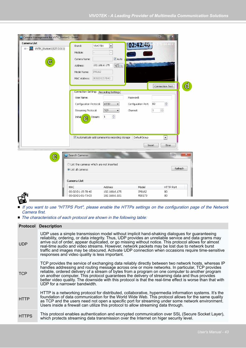
VIVOTEK - A Leading Provider of Multimedia Communication Solutions
User's Manual - 43
If you want to use "HTTPS Port", please enable the HTTPs settings on the configuration page of the Network Camera first.
The characteristics of each protocol are shown in the following table:
Protocol Description
UDP
UDP uses a simple transmission model without implicit hand-shaking dialogues for guaranteeing reliability, ordering, or data integrity. Thus, UDP provides an unreliable service and data grams may arrive out of order, appear duplicated, or go missing without notice. This protocol allows for almost real-time audio and video streams. However, network packets may be lost due to network burst traffic and images may be obscured. Activate UDP connection when occasions require time-sensitive responses and video quality is less important.
TCP
TCP provides the service of exchanging data reliably directly between two network hosts, whereas IP handles addressing and routing message across one or more networks. In particular, TCP provides reliable, ordered delivery of a stream of bytes from a program on one computer to another program on another computer. This protocol guarantees the delivery of streaming data and thus provides better video quality. The downside with this protocol is that the real-time effect is worse than that with UDP for a narrower bandwidth.
HTTPHTTP is a networking protocol for distributed, collaborative, hypermedia information systems. It’s the foundation of data communication for the World Wide Web. This protocol allows for the same quality as TCP and the users need not open a specific port for streaming under some network environment. Users inside a firewall can utilize this protocol to allow streaming data through.
HTTPS This protocol enables authentication and encrypted communication over SSL (Secure Socket Layer), which protects streaming data transmission over the Internet on higer security level.
d
c
c
c
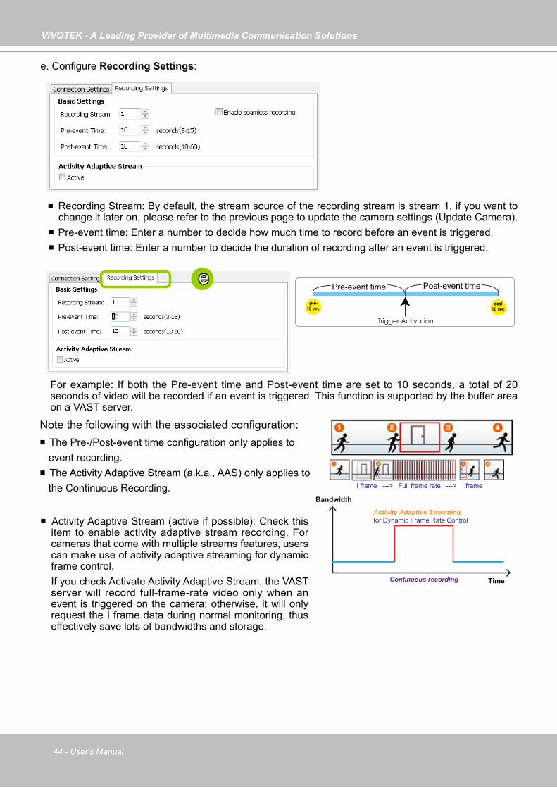
VIVOTEK - A Leading Provider of Multimedia Communication Solutions
44 - User's Manual
Recording Stream: By default, the stream source of the recording stream is stream 1, if you want to change it later on, please refer to the previous page to update the camera settings (Update Camera).
Pre-event time: Enter a number to decide how much time to record before an event is triggered. Post-event time: Enter a number to decide the duration of recording after an event is triggered.
For example: If both the Pre-event time and Post-event time are set to 10 seconds, a total of 20 seconds of video will be recorded if an event is triggered. This function is supported by the buffer area on a VAST server.
Activity Adaptive Stream (active if possible): Check this item to enable activity adaptive stream recording. For cameras that come with multiple streams features, users can make use of activity adaptive streaming for dynamic frame control.If you check Activate Activity Adaptive Stream, the VAST server will record full-frame-rate video only when an event is triggered on the camera; otherwise, it will only request the I frame data during normal monitoring, thus effectively save lots of bandwidths and storage.
Time
Bandwidth
Bandwidth
Activity Adaptive Streaming for Dynamic Frame Rate Control
I frame ---> Full frame rate ---> I frame
Continuous recording
post-10 sec.
pre-10 sec.
Trigger Activation
Pre-event time Post-event timee
Note the following with the associated configuration: The Pre-/Post-event time configuration only applies to event recording. The Activity Adaptive Stream (a.k.a., AAS) only applies to the Continuous Recording.
e. Configure Recording Settings:

VIVOTEK - A Leading Provider of Multimedia Communication Solutions
User's Manual - 45
f. The device will automatically be assigned to the default recording group. Deselect the item if you want to cancel this setting.
g. You can deselect the "Auto" checkbox behind the Camera Name entry, and manually enter a name of your choice, such as "East alley bullet." This name will be used as the folder name for the recorded video files. An index number will still be appended to the folder name. Note that if this name is changed when the recording is taking place, the configuration change will not take effect until the next day.
h. When all settings are completed, click Insert to add the device to the station. The device will be displayed under the Camera List on the left.
i. To insert additional devices to the station, repeat the above steps. j. When completed, click Close to exit the camera management window.k. Back to the main window, you will find the newly-inserted devices displayed under the station and the
live video in the video cell.
fh j
hg
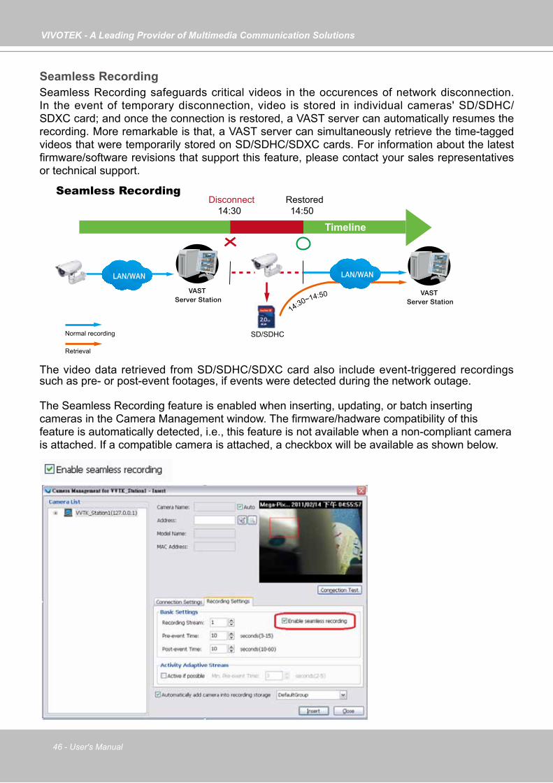
VIVOTEK - A Leading Provider of Multimedia Communication Solutions
46 - User's Manual
Seamless RecordingSeamless Recording safeguards critical videos in the occurences of network disconnection. In the event of temporary disconnection, video is stored in individual cameras' SD/SDHC/SDXC card; and once the connection is restored, a VAST server can automatically resumes the recording. More remarkable is that, a VAST server can simultaneously retrieve the time-tagged videos that were temporarily stored on SD/SDHC/SDXC cards. For information about the latest firmware/software revisions that support this feature, please contact your sales representatives or technical support.
The video data retrieved from SD/SDHC/SDXC card also include event-triggered recordings such as pre- or post-event footages, if events were detected during the network outage.
VAST Server Station
14:30 14:50Disconnect Restored
Timeline
LAN/WAN
VAST Server Station
LAN/WAN
14:30~14:50
Seamless Recording
SD/SDHCNormal recording
Retrieval
The Seamless Recording feature is enabled when inserting, updating, or batch inserting cameras in the Camera Management window. The firmware/hadware compatibility of this feature is automatically detected, i.e., this feature is not available when a non-compliant camera is attached. If a compatible camera is attached, a checkbox will be available as shown below.
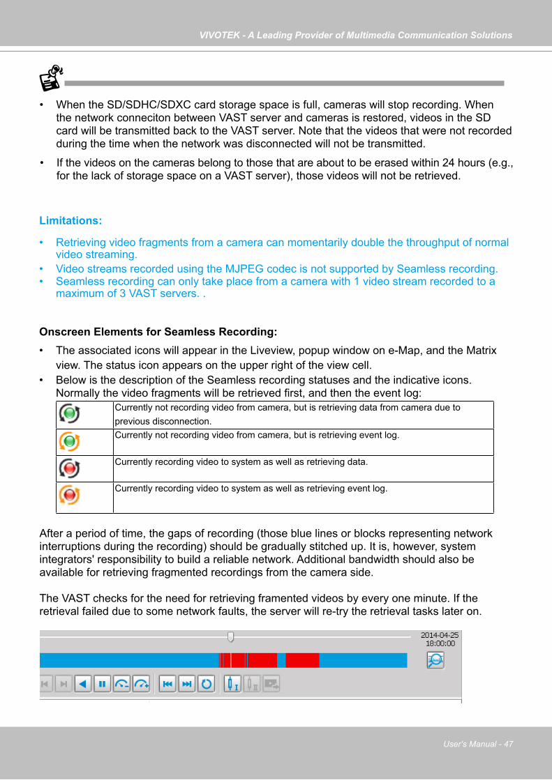
VIVOTEK - A Leading Provider of Multimedia Communication Solutions
User's Manual - 47
• When the SD/SDHC/SDXC card storage space is full, cameras will stop recording. When the network conneciton between VAST server and cameras is restored, videos in the SD card will be transmitted back to the VAST server. Note that the videos that were not recorded during the time when the network was disconnected will not be transmitted.
• If the videos on the cameras belong to those that are about to be erased within 24 hours (e.g., for the lack of storage space on a VAST server), those videos will not be retrieved.
Limitations:
• Retrieving video fragments from a camera can momentarily double the throughput of normal video streaming.
• Video streams recorded using the MJPEG codec is not supported by Seamless recording.• Seamless recording can only take place from a camera with 1 video stream recorded to a
maximum of 3 VAST servers. .
Onscreen Elements for Seamless Recording:• The associated icons will appear in the Liveview, popup window on e-Map, and the Matrix
view. The status icon appears on the upper right of the view cell. • Below is the description of the Seamless recording statuses and the indicative icons.
Normally the video fragments will be retrieved first, and then the event log: Currently not recording video from camera, but is retrieving data from camera due to previous disconnection. Currently not recording video from camera, but is retrieving event log.
Currently recording video to system as well as retrieving data.
Currently recording video to system as well as retrieving event log.
After a period of time, the gaps of recording (those blue lines or blocks representing network interruptions during the recording) should be gradually stitched up. It is, however, system integrators' responsibility to build a reliable network. Additional bandwidth should also be available for retrieving fragmented recordings from the camera side.
The VAST checks for the need for retrieving framented videos by every one minute. If the retrieval failed due to some network faults, the server will re-try the retrieval tasks later on.
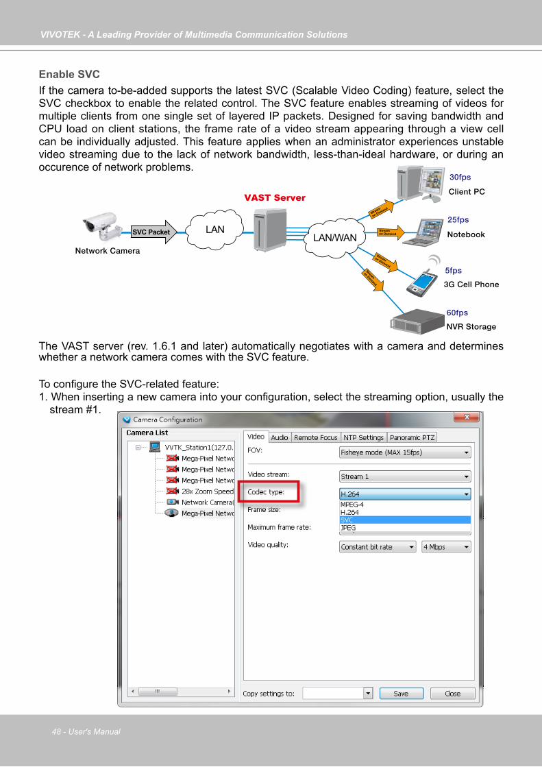
VIVOTEK - A Leading Provider of Multimedia Communication Solutions
48 - User's Manual
Enable SVC If the camera to-be-added supports the latest SVC (Scalable Video Coding) feature, select the SVC checkbox to enable the related control. The SVC feature enables streaming of videos for multiple clients from one single set of layered IP packets. Designed for saving bandwidth and CPU load on client stations, the frame rate of a video stream appearing through a view cell can be individually adjusted. This feature applies when an administrator experiences unstable video streaming due to the lack of network bandwidth, less-than-ideal hardware, or during an occurence of network problems.
The VAST server (rev. 1.6.1 and later) automatically negotiates with a camera and determines whether a network camera comes with the SVC feature. To configure the SVC-related feature:1. When inserting a new camera into your configuration, select the streaming option, usually the
stream #1.
VAST Server
Notebook
3G Cell Phone
Client PC
5fps
25fps
30fps
LAN
NVR Storage
60fps
LAN/WANSVC Packet
Stream
on Demand
Stream on Demand
Stream on Demand
Stream
on Demand
Network Camera

VIVOTEK - A Leading Provider of Multimedia Communication Solutions
User's Manual - 49
2. Right-click on the view cell of an SVC-enabled camera. Select SVC fps adjust bar.
3. A slide bar will appear above the view cell. Click and drag the slide bar. A numeric indicator will display the current selection. See below for the frame rates represented by the numeric indicator.
Indicator Frames per second (fps)Maximum 30
7 266 225 184 123 82 41 1
Minimum 1/4
NOTE:
The SVC feature only applies to H.264 and MJPEG streams. It is not applicable to MPEG-4 streams. Please refer to Configuration -> Media -> Video for individaul stream settings.
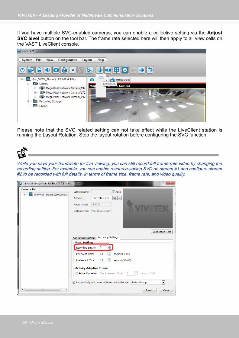
VIVOTEK - A Leading Provider of Multimedia Communication Solutions
50 - User's Manual
If you have multiple SVC-enabled cameras, you can enable a collective setting via the Adjust SVC level button on the tool bar. The frame rate selected here will then apply to all view cells on the VAST LiveClient console.
Please note that the SVC related setting can not take effect while the LiveClient station is running the Layout Rotation. Stop the layout rotation before configuring the SVC function.
While you save your bandwidth for live viewing, you can still record full-frame-rate video by changing the recording setting. For example, you can enable resource-saving SVC on stream #1 and configure stream #2 to be recorded with full details, in terms of frame size, frame rate, and video quality.
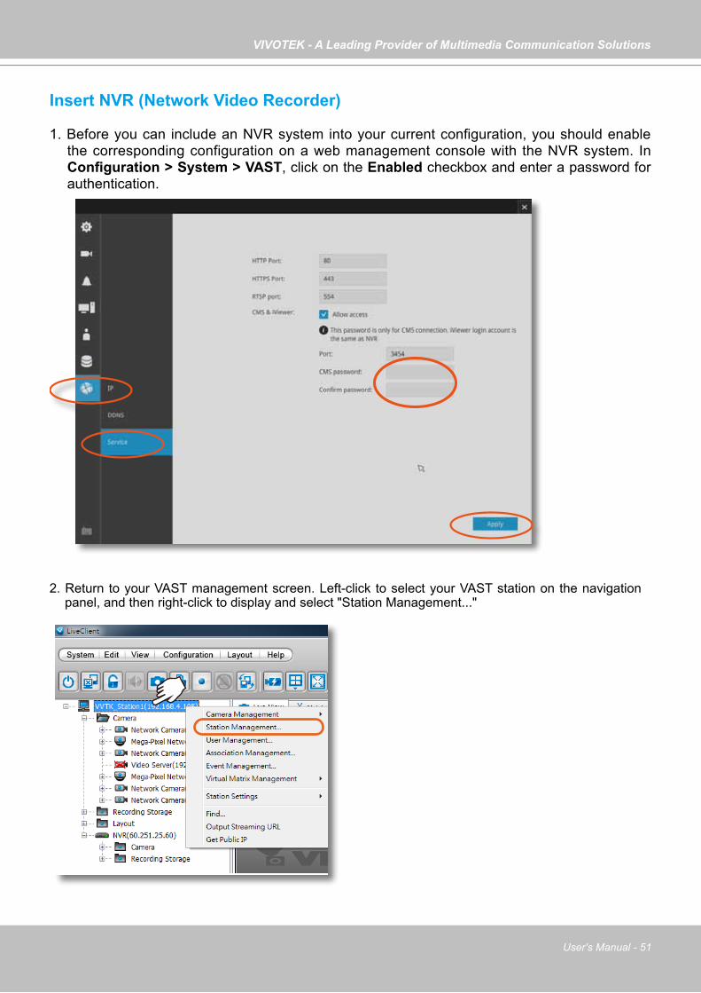
VIVOTEK - A Leading Provider of Multimedia Communication Solutions
User's Manual - 51
Insert NVR (Network Video Recorder)
1. Before you can include an NVR system into your current configuration, you should enable the corresponding configuration on a web management console with the NVR system. In Configuration > System > VAST, click on the Enabled checkbox and enter a password for authentication.
2. Return to your VAST management screen. Left-click to select your VAST station on the navigation panel, and then right-click to display and select "Station Management..."
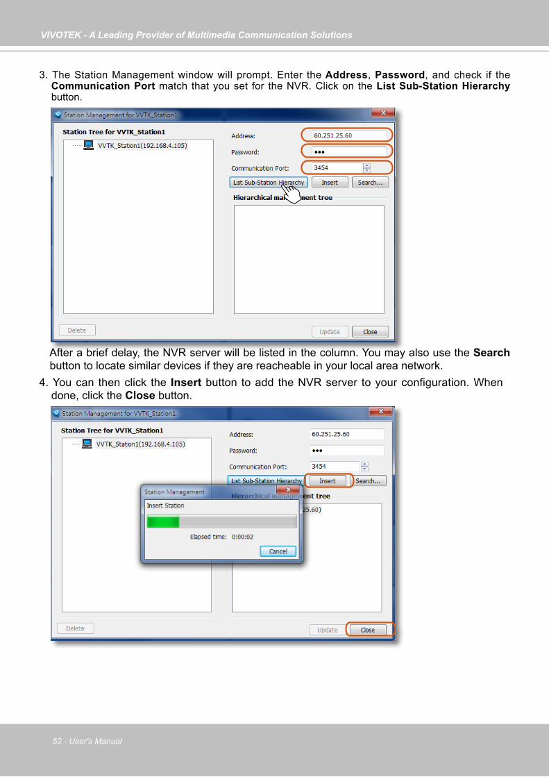
VIVOTEK - A Leading Provider of Multimedia Communication Solutions
52 - User's Manual
3. The Station Management window will prompt. Enter the Address, Password, and check if the Communication Port match that you set for the NVR. Click on the List Sub-Station Hierarchy button.
After a brief delay, the NVR server will be listed in the column. You may also use the Search button to locate similar devices if they are reacheable in your local area network.
4. You can then click the Insert button to add the NVR server to your configuration. When done, click the Close button.

VIVOTEK - A Leading Provider of Multimedia Communication Solutions
User's Manual - 53
5. The NVR will appear in the navigation panel along with its subordinate cameras.
Insert a Video Server
1. Left-click on your VAST station, and then right-click to display the Camera Management command. Let your cursor stay on the command for a second and then move to the Insert Camera command. Click on the command to open its configuration window.
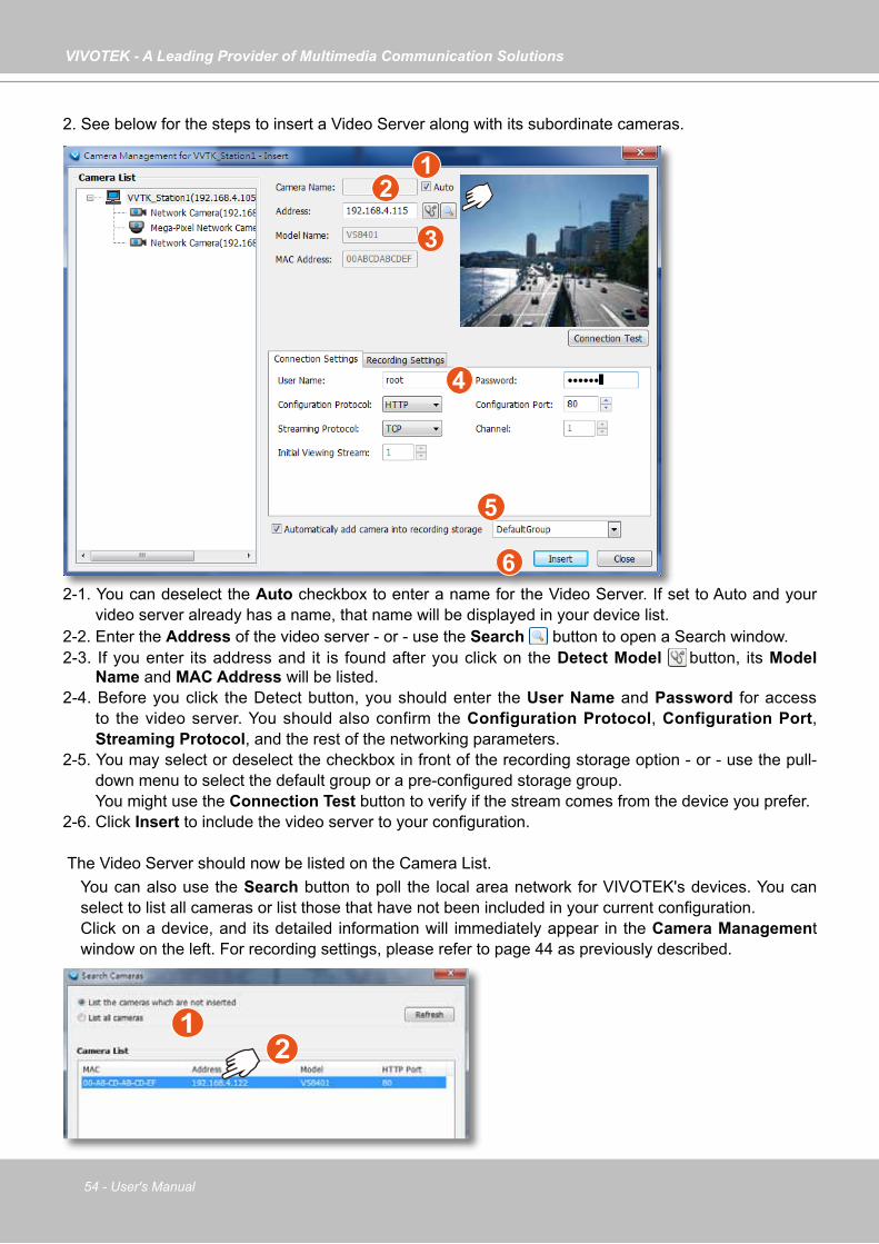
VIVOTEK - A Leading Provider of Multimedia Communication Solutions
54 - User's Manual
2. See below for the steps to insert a Video Server along with its subordinate cameras.
2-1. You can deselect the Auto checkbox to enter a name for the Video Server. If set to Auto and your video server already has a name, that name will be displayed in your device list.
2-2. Enter the Address of the video server - or - use the Search button to open a Search window. 2-3. If you enter its address and it is found after you click on the Detect Model button, its Model
Name and MAC Address will be listed. 2-4. Before you click the Detect button, you should enter the User Name and Password for access
to the video server. You should also confirm the Configuration Protocol, Configuration Port, Streaming Protocol, and the rest of the networking parameters.
2-5. You may select or deselect the checkbox in front of the recording storage option - or - use the pull-down menu to select the default group or a pre-configured storage group.
You might use the Connection Test button to verify if the stream comes from the device you prefer. 2-6. Click Insert to include the video server to your configuration.
The Video Server should now be listed on the Camera List. You can also use the Search button to poll the local area network for VIVOTEK's devices. You can
select to list all cameras or list those that have not been included in your current configuration. Click on a device, and its detailed information will immediately appear in the Camera Management
window on the left. For recording settings, please refer to page 44 as previously described.
12
3
4
5
6
12
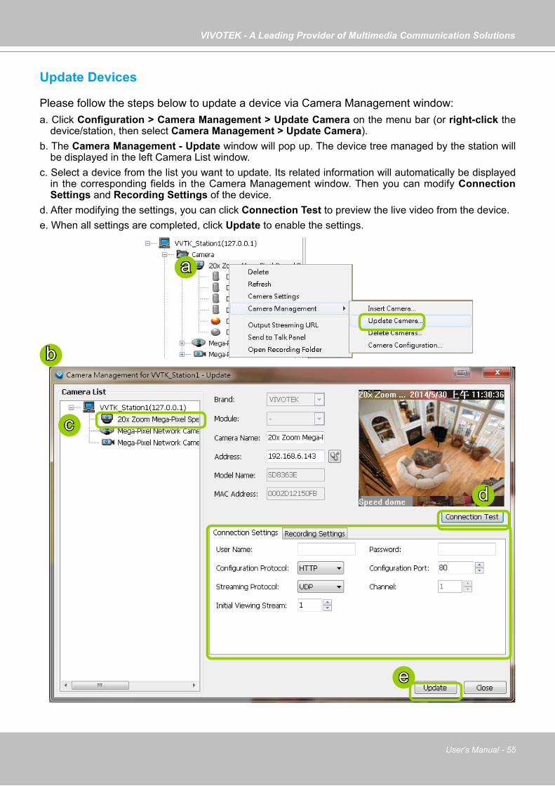
VIVOTEK - A Leading Provider of Multimedia Communication Solutions
User's Manual - 55
Update Devices
Please follow the steps below to update a device via Camera Management window:a. Click Configuration > Camera Management > Update Camera on the menu bar (or right-click the
device/station, then select Camera Management > Update Camera).b. The Camera Management - Update window will pop up. The device tree managed by the station will
be displayed in the left Camera List window.c. Select a device from the list you want to update. Its related information will automatically be displayed
in the corresponding fields in the Camera Management window. Then you can modify Connection Settings and Recording Settings of the device.
d. After modifying the settings, you can click Connection Test to preview the live video from the device.e. When all settings are completed, click Update to enable the settings.
b
c
e
d
a
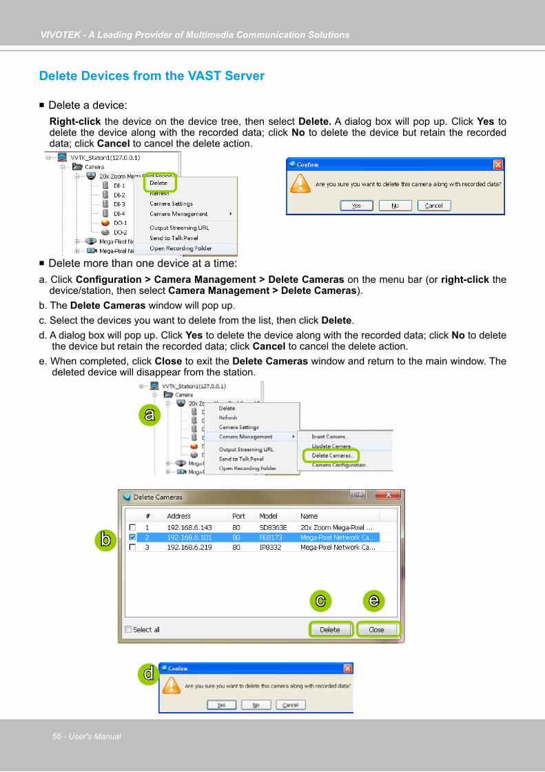
VIVOTEK - A Leading Provider of Multimedia Communication Solutions
56 - User's Manual
Delete Devices from the VAST Server
Delete a device:Right-click the device on the device tree, then select Delete. A dialog box will pop up. Click Yes to delete the device along with the recorded data; click No to delete the device but retain the recorded data; click Cancel to cancel the delete action.
Delete more than one device at a time:a. Click Configuration > Camera Management > Delete Cameras on the menu bar (or right-click the
device/station, then select Camera Management > Delete Cameras). b. The Delete Cameras window will pop up. c. Select the devices you want to delete from the list, then click Delete.d. A dialog box will pop up. Click Yes to delete the device along with the recorded data; click No to delete
the device but retain the recorded data; click Cancel to cancel the delete action.e. When completed, click Close to exit the Delete Cameras window and return to the main window. The
deleted device will disappear from the station.
b
a
c
d
e
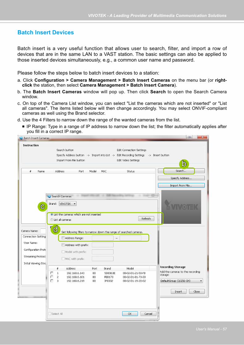
VIVOTEK - A Leading Provider of Multimedia Communication Solutions
User's Manual - 57
Batch Insert Devices
Batch insert is a very useful function that allows user to search, filter, and import a row of devices that are in the same LAN to a VAST station. The basic settings can also be applied to those inserted devices simultaneously, e.g., a common user name and password.
Please follow the steps below to batch insert devices to a station:a. Click Configuration > Camera Management > Batch Insert Cameras on the menu bar (or right-
click the station, then select Camera Management > Batch Insert Camera).b. The Batch Insert Cameras window will pop up. Then click Search to open the Search Camera
window.c. On top of the Camera List window, you can select "List the cameras which are not inserted" or "List
all cameras". The items listed below will then change accordingly. You may select ONVIF-compliant cameras as well using the Brand selector.
d. Use the 4 Filters to narrow down the range of the wanted cameras from the list. IP Range: Type in a range of IP address to narrow down the list; the filter automatically applies after
you fill in a correct IP range.
b
c
d
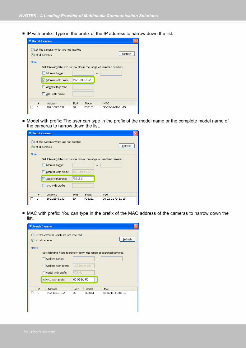
VIVOTEK - A Leading Provider of Multimedia Communication Solutions
58 - User's Manual
IP with prefix: Type in the prefix of the IP address to narrow down the list.
Model with prefix: The user can type in the prefix of the model name or the complete model name of the cameras to narrow down the list.
MAC with prefix: You can type in the prefix of the MAC address of the cameras to narrow down the list.
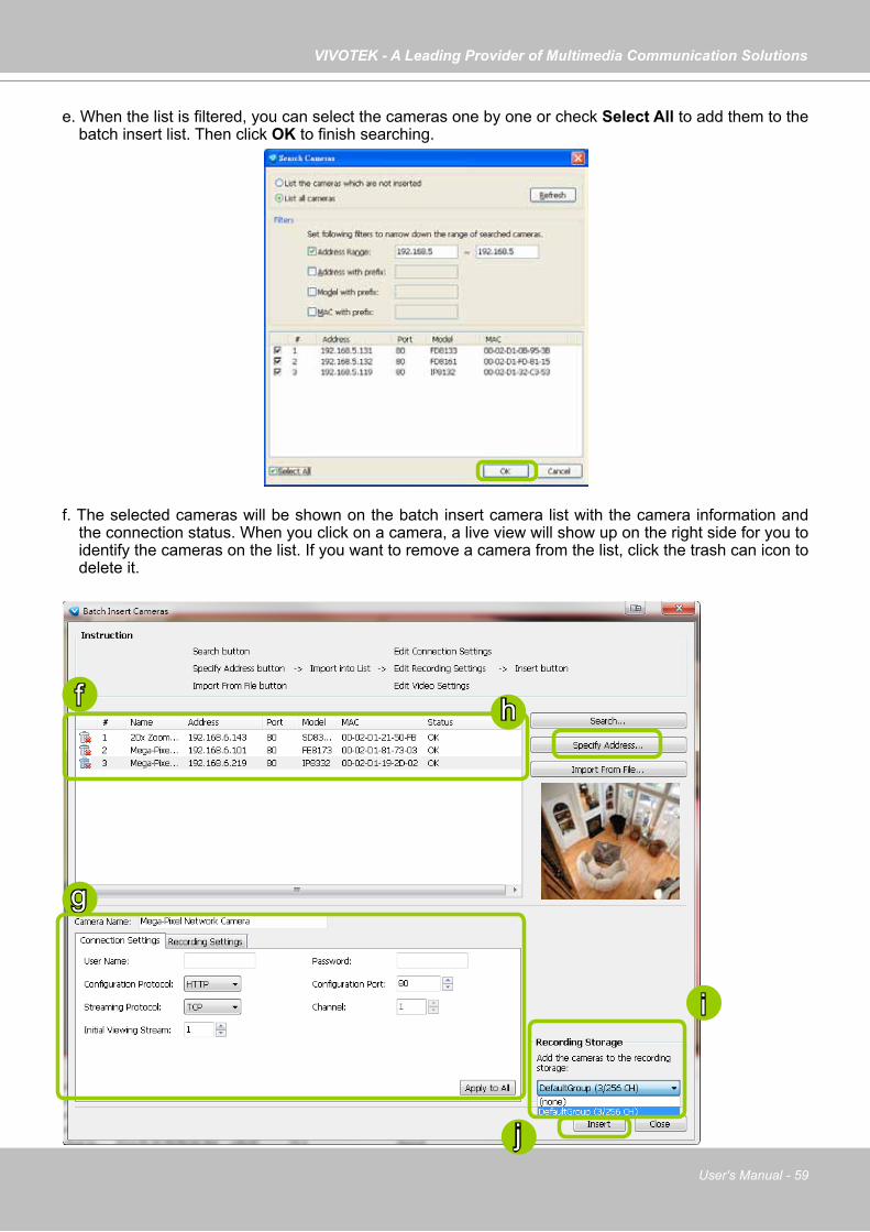
VIVOTEK - A Leading Provider of Multimedia Communication Solutions
User's Manual - 59
e. When the list is filtered, you can select the cameras one by one or check Select All to add them to the batch insert list. Then click OK to finish searching.
f. The selected cameras will be shown on the batch insert camera list with the camera information and the connection status. When you click on a camera, a live view will show up on the right side for you to identify the cameras on the list. If you want to remove a camera from the list, click the trash can icon to delete it.
g
f h
j
i
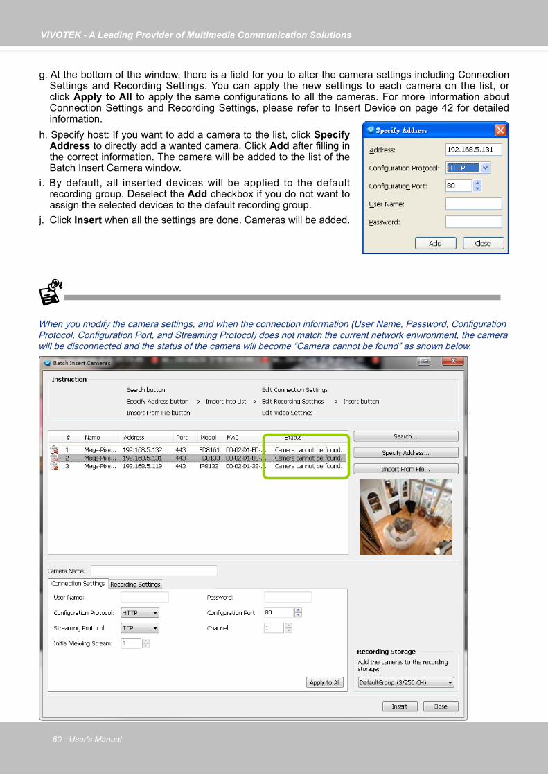
VIVOTEK - A Leading Provider of Multimedia Communication Solutions
60 - User's Manual
g. At the bottom of the window, there is a field for you to alter the camera settings including Connection Settings and Recording Settings. You can apply the new settings to each camera on the list, or click Apply to All to apply the same configurations to all the cameras. For more information about Connection Settings and Recording Settings, please refer to Insert Device on page 42 for detailed information.
When you modify the camera settings, and when the connection information (User Name, Password, Configuration Protocol, Configuration Port, and Streaming Protocol) does not match the current network environment, the camera will be disconnected and the status of the camera will become “Camera cannot be found” as shown below.
h. Specify host: If you want to add a camera to the list, click Specify Address to directly add a wanted camera. Click Add after filling in the correct information. The camera will be added to the list of the Batch Insert Camera window.
i. By default, all inserted devices will be applied to the default recording group. Deselect the Add checkbox if you do not want to assign the selected devices to the default recording group.
j. Click Insert when all the settings are done. Cameras will be added.

VIVOTEK - A Leading Provider of Multimedia Communication Solutions
User's Manual - 61
You can enter a User name and Password and use the Apply to All button to apply this combination to all selected cameras. This way, you do not need to change the user name and password for every individual cameras.
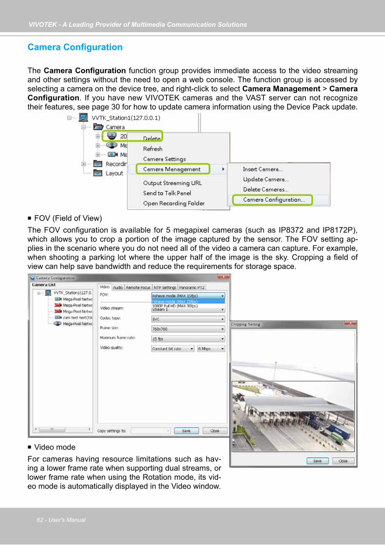
VIVOTEK - A Leading Provider of Multimedia Communication Solutions
62 - User's Manual
Camera Configuration
The Camera Configuration function group provides immediate access to the video streaming and other settings without the need to open a web console. The function group is accessed by selecting a camera on the device tree, and right-click to select Camera Management > Camera Configuration. If you have new VIVOTEK cameras and the VAST server can not recognize their features, see page 30 for how to update camera information using the Device Pack update.
FOV (Field of View)The FOV configuration is available for 5 megapixel cameras (such as IP8372 and IP8172P), which allows you to crop a portion of the image captured by the sensor. The FOV setting ap-plies in the scenario where you do not need all of the video a camera can capture. For example, when shooting a parking lot where the upper half of the image is the sky. Cropping a field of view can help save bandwidth and reduce the requirements for storage space.
Video modeFor cameras having resource limitations such as hav-ing a lower frame rate when supporting dual streams, or lower frame rate when using the Rotation mode, its vid-eo mode is automatically displayed in the Video window.

VIVOTEK - A Leading Provider of Multimedia Communication Solutions
User's Manual - 63
VideoThis tabbed window privides access to the selection of the live view stream, its compression co-dec, frame size, max. frame rate, and video quality. Note that the Constant Bit Rate methodol-ogy can be used to ensure that the size of video stream does not exceed a preferred threshold, regardless of the complexity or the changes of pixels in the image. You should use a maximum of 1080P as frame size and 6Mbps as constant bit rate for video streams managed by this system.
If your camera supports the Smart Stream function, the related options will be available with the Video quality. Note that only the Auto mode option will be available.
Auto: When set to Auto, only the moving objects and the areas around them will be displayed with the Foreground quality. The rest of the screen will be displayed with the Background (lower) quality.
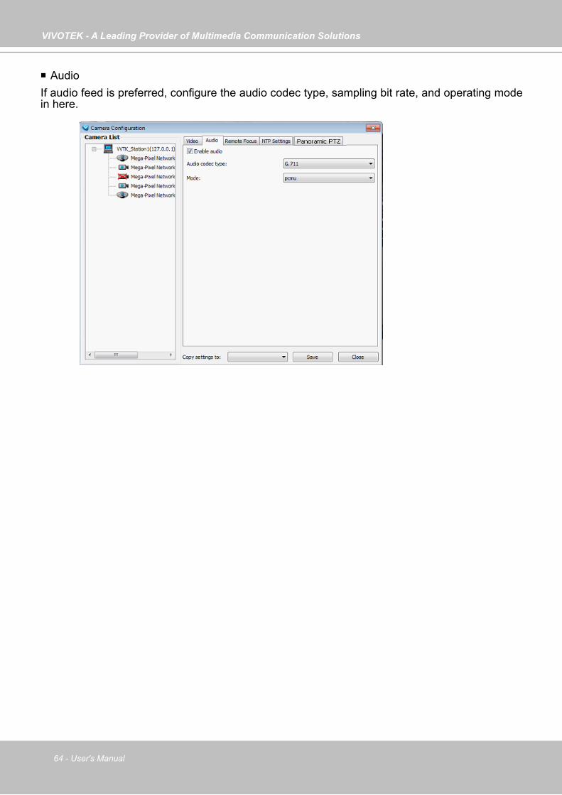
VIVOTEK - A Leading Provider of Multimedia Communication Solutions
64 - User's Manual
AudioIf audio feed is preferred, configure the audio codec type, sampling bit rate, and operating mode in here.
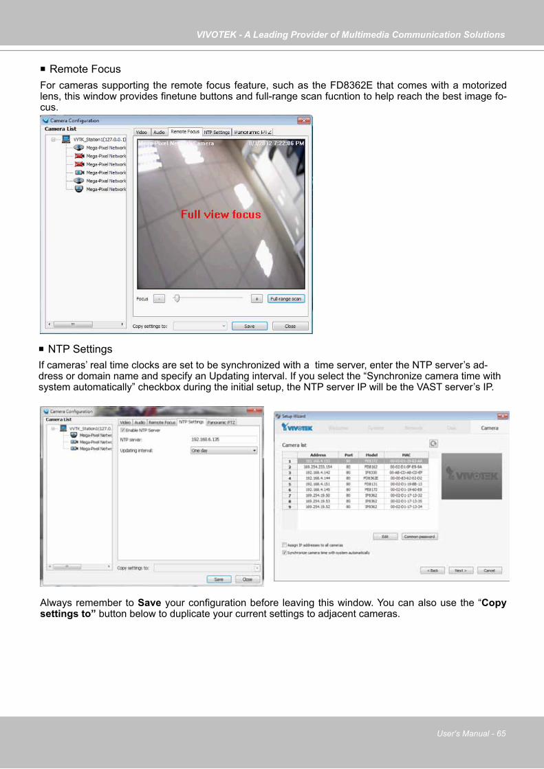
VIVOTEK - A Leading Provider of Multimedia Communication Solutions
User's Manual - 65
Remote FocusFor cameras supporting the remote focus feature, such as the FD8362E that comes with a motorized lens, this window provides finetune buttons and full-range scan fucntion to help reach the best image fo-cus.
Always remember to Save your configuration before leaving this window. You can also use the “Copy settings to” button below to duplicate your current settings to adjacent cameras.
NTP SettingsIf cameras’ real time clocks are set to be synchronized with a time server, enter the NTP server’s ad-dress or domain name and specify an Updating interval. If you select the “Synchronize camera time with system automatically” checkbox during the initial setup, the NTP server IP will be the VAST server’s IP.

VIVOTEK - A Leading Provider of Multimedia Communication Solutions
66 - User's Manual
Panoramic PTZPlease refer to Appendix A Panoramic PTZ configuration on page 249 or the Panoramic PTZ Installation Guide for more information.

VIVOTEK - A Leading Provider of Multimedia Communication Solutions
User's Manual - 67
View Live Videos
The server will automatically add a newly-inserted device to the video cell for live viewing. You also can double-click the target device or drag-and-drop the target device from the hierarchical management tree to the video cell.
Dual / Multiple Streams
For dual-stream devices, you can right-click on the focused cell to select stream 1 or stream 2. For multiple-stream devices, you can select from stream 1 ~ stream 4.
Fisheye Display Modes
By default, a circular view is displayed when a fisheye camera is successfully connected. To display Regional, Panoramic, or the combination of different views, right-click on a fisheye camera's live view to display the associated commands. The display modes available are: 1O (Original), 1P (Panoramic), 1R (Regional), 2P (2 Panoramic), 1O3R (1 Original & 3 Regional), 4R (Quad Regional), 1O8R (1 Original & 8 Regional), and 4R Pro (4 Proactive) modes.
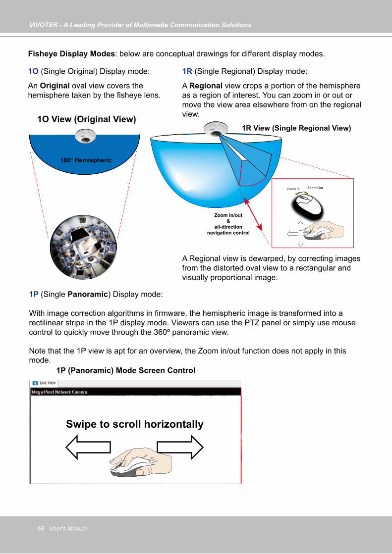
VIVOTEK - A Leading Provider of Multimedia Communication Solutions
68 - User's Manual
Fisheye Display Modes: below are conceptual drawings for different display modes.
1O View (Original View)
180° Hemispheric
1R View (Single Regional View)
Zoom in/out&
all-directionnavigation control
Zoom In Zoom Out
An Original oval view covers the hemisphere taken by the fisheye lens.
A Regional view crops a portion of the hemisphere as a region of interest. You can zoom in or out or move the view area elsewhere from on the regional view.
Swipe to scroll horizontally
1P (Single Panoramic) Display mode:
With image correction algorithms in firmware, the hemispheric image is transformed into a rectilinear stripe in the 1P display mode. Viewers can use the PTZ panel or simply use mouse control to quickly move through the 360º panoramic view.
Note that the 1P view is apt for an overview, the Zoom in/out function does not apply in this mode.
A Regional view is dewarped, by correcting images from the distorted oval view to a rectangular and visually proportional image.
1O (Single Original) Display mode: 1R (Single Regional) Display mode:
1P (Panoramic) Mode Screen Control
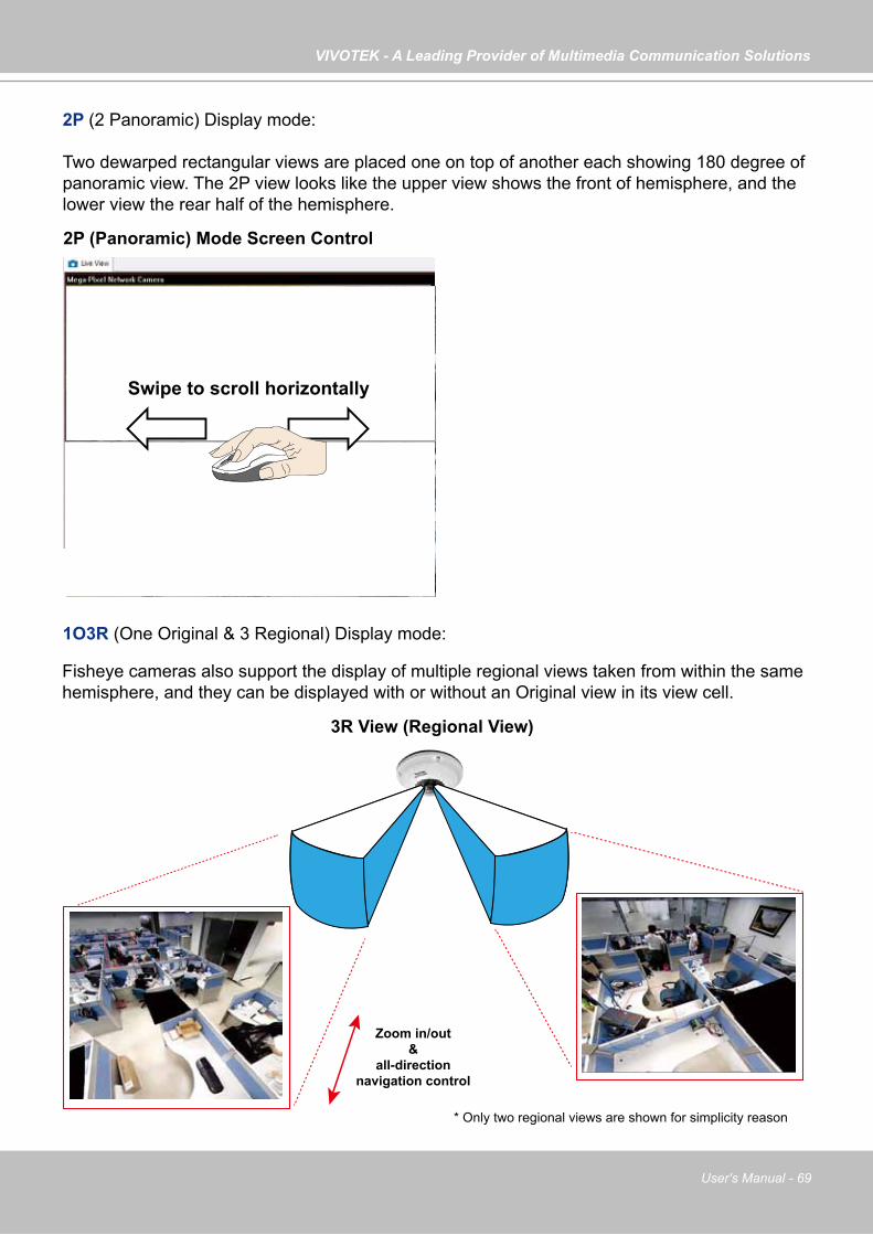
VIVOTEK - A Leading Provider of Multimedia Communication Solutions
User's Manual - 69
Swipe to scroll horizontally
2P (2 Panoramic) Display mode:
Two dewarped rectangular views are placed one on top of another each showing 180 degree of panoramic view. The 2P view looks like the upper view shows the front of hemisphere, and the lower view the rear half of the hemisphere.
Zoom in/out&
all-directionnavigation control
* Only two regional views are shown for simplicity reason
Fisheye cameras also support the display of multiple regional views taken from within the same hemisphere, and they can be displayed with or without an Original view in its view cell.
3R View (Regional View)
1O3R (One Original & 3 Regional) Display mode:
2P (Panoramic) Mode Screen Control
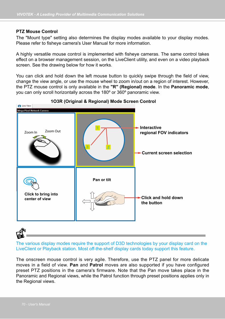
VIVOTEK - A Leading Provider of Multimedia Communication Solutions
70 - User's Manual
The various display modes require the support of D3D technologies by your display card on the LiveClient or Playback station. Most off-the-shelf display cards today support this feature.
The onscreen mouse control is very agile. Therefore, use the PTZ panel for more delicate moves in a field of view. Pan and Patrol moves are also supported if you have configured preset PTZ positions in the camera's firmware. Note that the Pan move takes place in the Panoramic and Regional views, while the Patrol function through preset positions applies only in the Regional views.
PTZ Mouse Control The "Mount type" setting also determines the display modes available to your display modes. Please refer to fisheye camera's User Manual for more information.
A highly versatile mouse control is implemented with fisheye cameras. The same control takes effect on a browser management session, on the LiveClient utility, and even on a video playback screen. See the drawing below for how it works. You can click and hold down the left mouse button to quickly swipe through the field of view, change the view angle, or use the mouse wheel to zoom in/out on a region of interest. However, the PTZ mouse control is only available in the "R" (Regional) mode. In the Panoramic mode, you can only scroll horizontally across the 180º or 360º panoramic view.
Current screen selection
Zoom In Zoom Out
Click to bring into center of view
Pan or tilt
1
23
Interactiveregional FOV indicators
Click and hold downthe button
1O3R (Original & Regional) Mode Screen Control
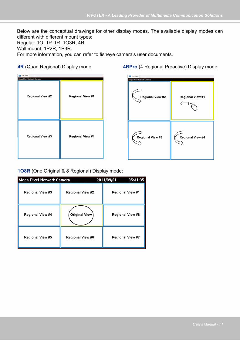
VIVOTEK - A Leading Provider of Multimedia Communication Solutions
User's Manual - 71
Regional View #1
Regional View #3
Regional View #2
Regional View #4
Regional View #1Regional View #2
Original View
Regional View #3
Regional View #6Regional View #5 Regional View #7
Regional View #4 Regional View #8
Regional View #1
Regional View #3
Regional View #2
Regional View #4
Below are the conceptual drawings for other display modes. The available display modes can different with different mount types: Regular: 1O, 1P, 1R, 1O3R, 4R.Wall mount: 1P2R, 1P3R. For more information, you can refer to fisheye camera's user documents.
4R (Quad Regional) Display mode:
1O8R (One Original & 8 Regional) Display mode:
4RPro (4 Regional Proactive) Display mode:
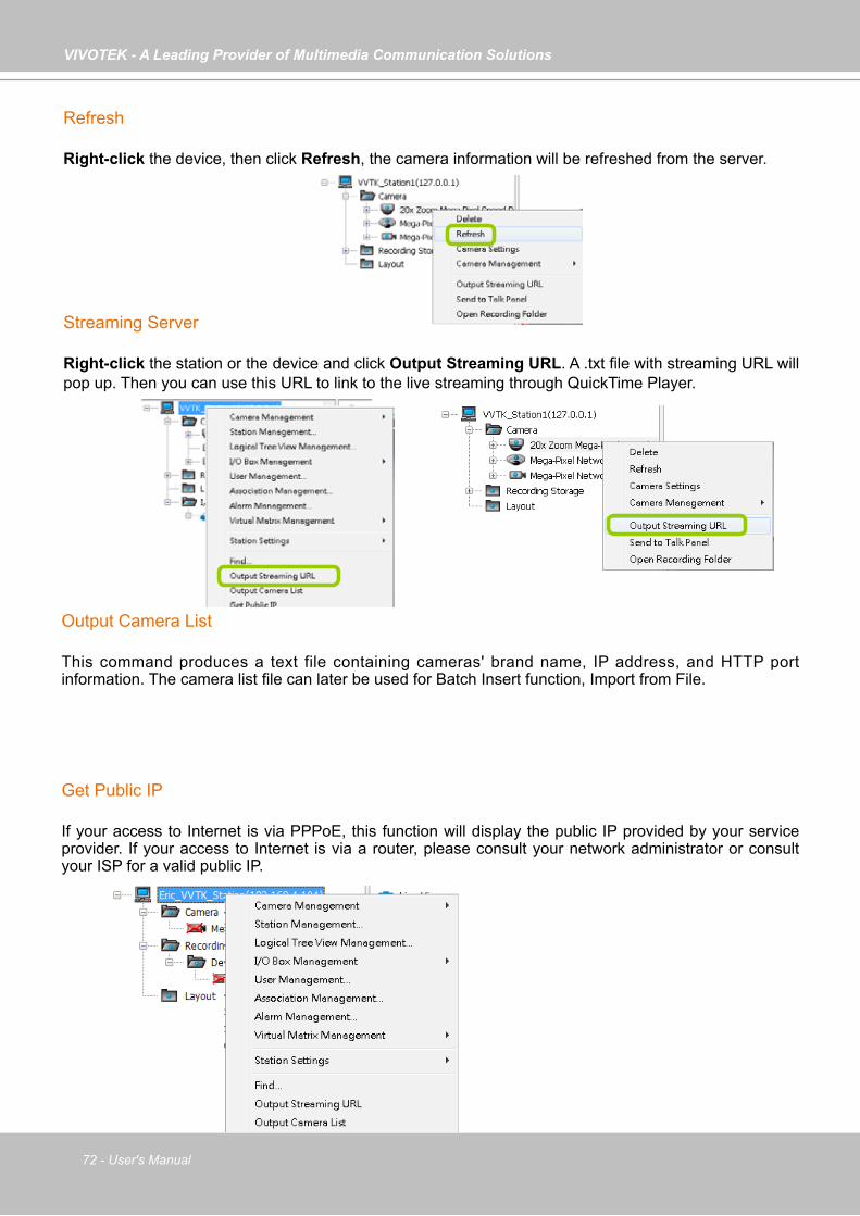
VIVOTEK - A Leading Provider of Multimedia Communication Solutions
72 - User's Manual
Refresh
Right-click the device, then click Refresh, the camera information will be refreshed from the server.
Streaming Server
Right-click the station or the device and click Output Streaming URL. A .txt file with streaming URL will pop up. Then you can use this URL to link to the live streaming through QuickTime Player.
Get Public IP
If your access to Internet is via PPPoE, this function will display the public IP provided by your service provider. If your access to Internet is via a router, please consult your network administrator or consult your ISP for a valid public IP.
Output Camera List
This command produces a text file containing cameras' brand name, IP address, and HTTP port information. The camera list file can later be used for Batch Insert function, Import from File.
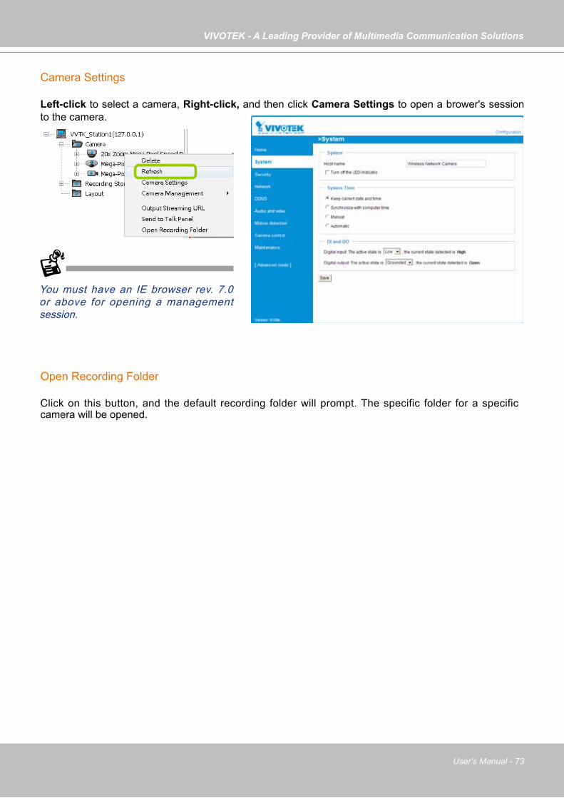
VIVOTEK - A Leading Provider of Multimedia Communication Solutions
User's Manual - 73
Camera Settings
Left-click to select a camera, Right-click, and then click Camera Settings to open a brower's session to the camera.
You must have an IE browser rev. 7.0 or above for opening a management session.
Open Recording Folder
Click on this button, and the default recording folder will prompt. The specific folder for a specific camera will be opened.
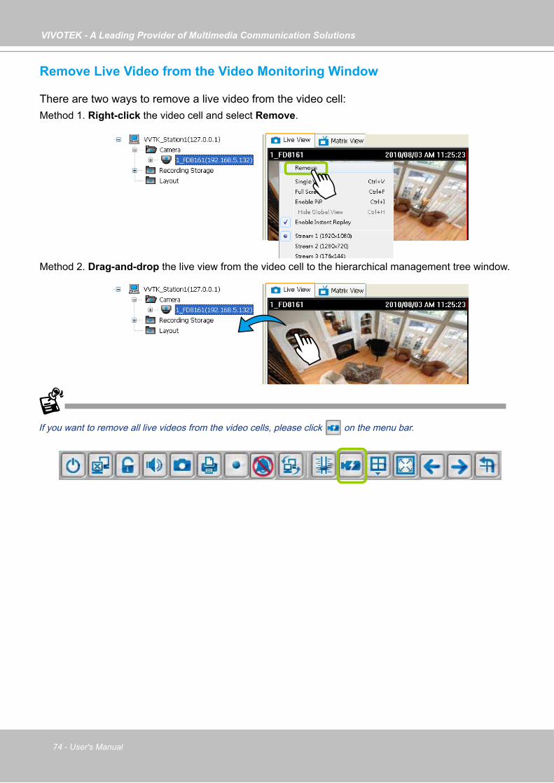
VIVOTEK - A Leading Provider of Multimedia Communication Solutions
74 - User's Manual
Remove Live Video from the Video Monitoring Window
There are two ways to remove a live video from the video cell: Method 1. Right-click the video cell and select Remove.
Method 2. Drag-and-drop the live view from the video cell to the hierarchical management tree window.
If you want to remove all live videos from the video cells, please click on the menu bar.

VIVOTEK - A Leading Provider of Multimedia Communication Solutions
User's Manual - 75
How to Change the VAST LiveClient Layout
Changing the Layout of the Live Video Monitoring Window
VIVOTEK VAST LiveClient supports up to 32-CH simultaneous video viewing on a single monitor and allows you to change the layout of the live video monitoring window based on the number of inserted devices.
Switch Video Channels
To move a video channel to another empty video cell, drag-and-drop the view to the target video cell.
To switch two different channels, drag-and-drop one view to the other, then the two different channels will be switched to the opposite.
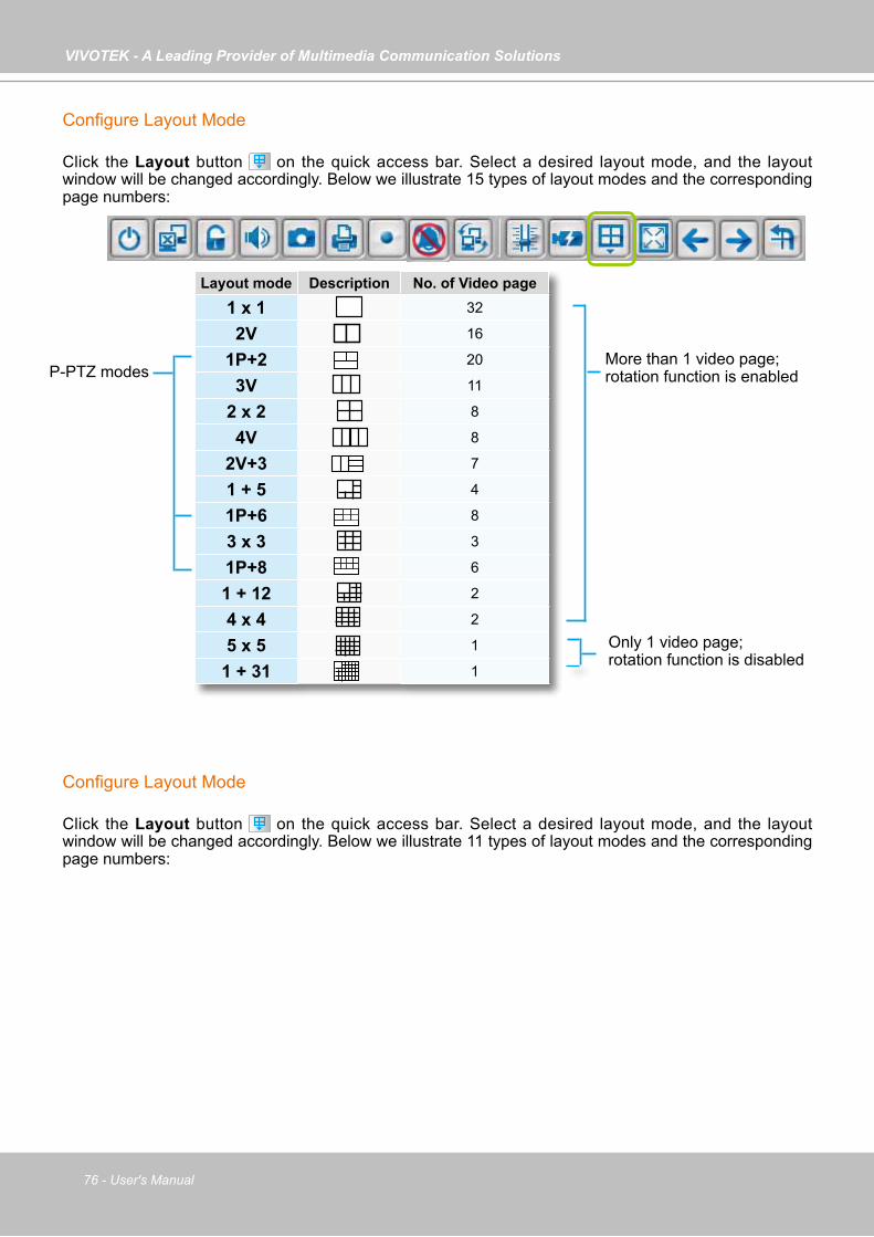
VIVOTEK - A Leading Provider of Multimedia Communication Solutions
76 - User's Manual
Configure Layout Mode
Click the Layout button on the quick access bar. Select a desired layout mode, and the layout window will be changed accordingly. Below we illustrate 15 types of layout modes and the corresponding page numbers:
Layout mode Description No. of Video page
1 x 1 32
2V 16
1P+2 20
3V 11
2 x 2 8
4V 8
2V+3 7
1 + 5 4
1P+6 8
3 x 3 3
1P+8 6
1 + 12 2
4 x 4 2
5 x 5 1
1 + 31 1
More than 1 video page; rotation function is enabled
Only 1 video page; rotation function is disabled
P-PTZ modes
Configure Layout Mode
Click the Layout button on the quick access bar. Select a desired layout mode, and the layout window will be changed accordingly. Below we illustrate 11 types of layout modes and the corresponding page numbers:
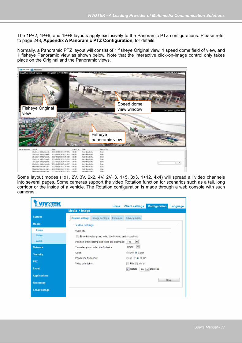
VIVOTEK - A Leading Provider of Multimedia Communication Solutions
User's Manual - 77
Some layout modes (1x1, 2V, 3V, 2x2, 4V, 2V+3, 1+5, 3x3, 1+12, 4x4) will spread all video channels into several pages. Some cameras support the video Rotation function for scenarios such as a tall, long corridor or the inside of a vehicle. The Rotation configuration is made through a web console with such cameras.
The 1P+2, 1P+6, and 1P+8 layouts apply exclusively to the Panoramic PTZ configurations. Please refer to page 248, Appendix A Panoramic PTZ Configuration, for details.
Normally, a Panoramic PTZ layout will consist of 1 fisheye Original view, 1 speed dome field of view, and 1 fisheye Panoramic view as shown below. Note that the interactive click-on-image control only takes place on the Original and the Panoramic views.
Fisheye panoramic view
Fisheye Originalview
Speed domeview window
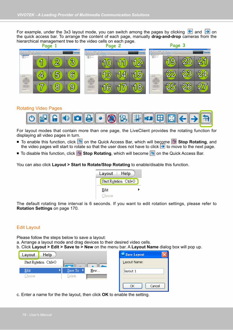
VIVOTEK - A Leading Provider of Multimedia Communication Solutions
78 - User's Manual
For example, under the 3x3 layout mode, you can switch among the pages by clicking and on the quick access bar. To arrange the content of each page, manually drag-and-drop cameras from the hierarchical management tree to the video cells on each page.
Rotating Video Pages
For layout modes that contain more than one page, the LiveClient provides the rotating function for displaying all video pages in turn. To enable this function, click on the Quick Access Bar, which will become Stop Rotating, and
the video pages will start to rotate so that the user does not have to click to move to the next page. To disable this function, click Stop Rotating, which will become on the Quick Access Bar.
You can also click Layout > Start to Rotate/Stop Rotating to enable/disable this function.
The default rotating time interval is 6 seconds. If you want to edit rotation settings, please refer to Rotation Settings on page 170.
Edit Layout
Please follow the steps below to save a layout:a. Arrange a layout mode and drag devices to their desired video cells.b. Click Layout > Edit > Save to > New on the menu bar. A Layout Name dialog box will pop up.
c. Enter a name for the the layout, then click OK to enable the setting.
1 2 3
164 5 67 8 9
10 11 1213 14 15
Page 1 Page 2 Page 3
17 18
1922
212023 24
25 26 27

VIVOTEK - A Leading Provider of Multimedia Communication Solutions
User's Manual - 79
d. Back to the monitoring window, the new layout will be displayed under the hierarchical management tree as shown below. You can save up to 10 layouts.
e. To change to another layout, double-click the layout options on the hierarchical management tree, or click Layout > Choose on the menu bar to select a desired layout.
If you want to edit an existing layout, arrange a layout mode and drag devices to the desired video cells, then click Layout > Edit > Save to > New to save as a new layout or an existing layout to replace with the new one.
If you want to delete an existing layout, right-click the layout item on the hierarchical management tree or click Layout > Edit > Delete on the menu bar to delete it.
Whenever you close the LiveClient or Playback programs and changes in screen layout have been made, you will be prompted to save your current configuration.
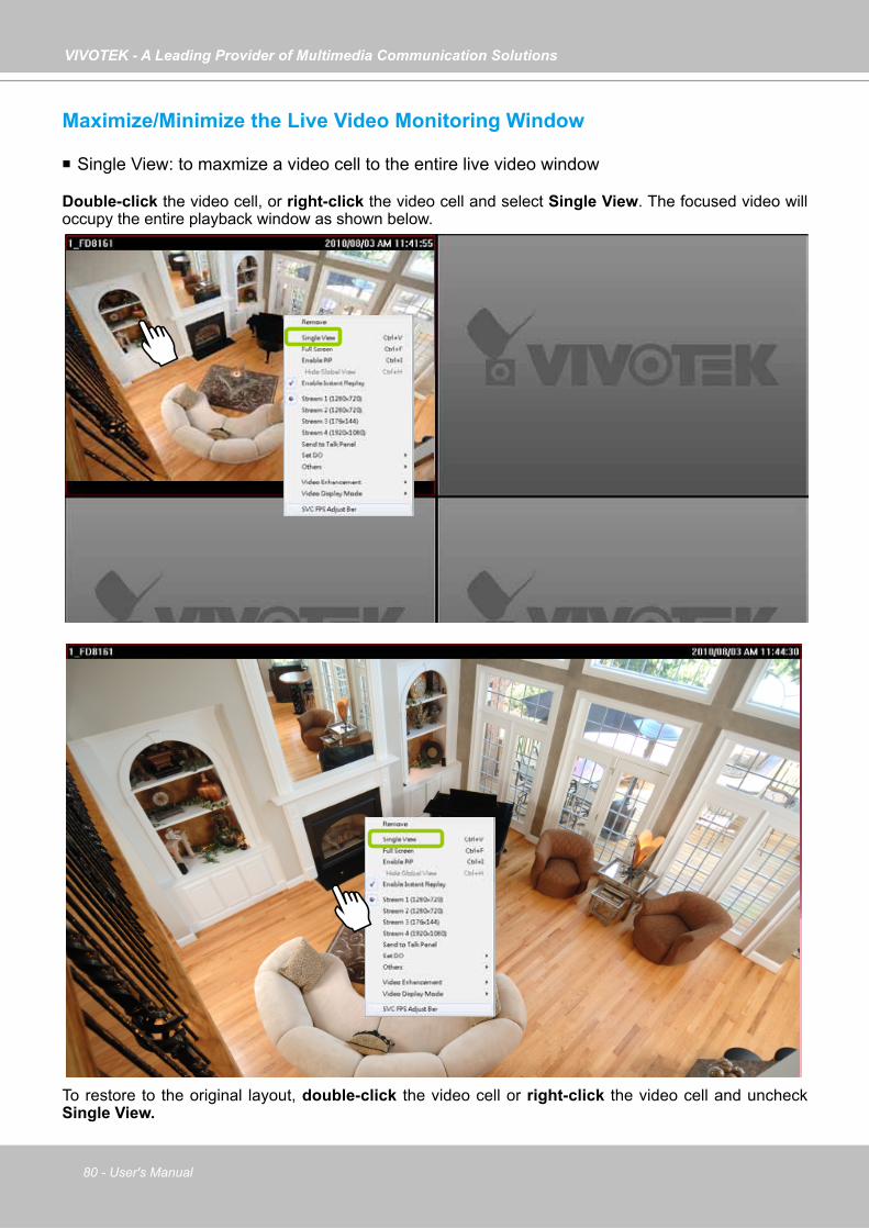
VIVOTEK - A Leading Provider of Multimedia Communication Solutions
80 - User's Manual
Maximize/Minimize the Live Video Monitoring Window
Single View: to maxmize a video cell to the entire live video window
Double-click the video cell, or right-click the video cell and select Single View. The focused video will occupy the entire playback window as shown below.
To restore to the original layout, double-click the video cell or right-click the video cell and uncheck Single View.
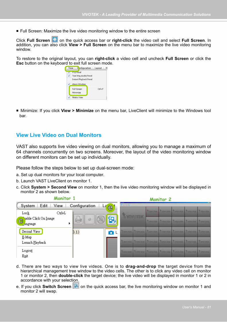
VIVOTEK - A Leading Provider of Multimedia Communication Solutions
User's Manual - 81
Full Screen: Maximize the live video monitoring window to the entire screen
Click Full Screen on the quick access bar or right-click the video cell and select Full Screen. In addition, you can also click View > Full Screen on the menu bar to maximize the live video monitoring window.
To restore to the original layout, you can right-click a video cell and uncheck Full Screen or click the Esc button on the keyboard to exit full screen mode.
Minimize: If you click View > Minimize on the menu bar, LiveClient will minimize to the Windows tool bar.
View Live Video on Dual Monitors
VAST also supports live video viewing on dual monitors, allowing you to manage a maximum of 64 channels concurrently on two screens. Moreover, the layout of the video monitoring window on different monitors can be set up individually.
Please follow the steps below to set up dual-screen mode:a. Set up dual monitors for your local computer.b. Launch VAST LiveClient on monitor 1.c. Click System > Second View on monitor 1, then the live video monitoring window will be displayed in
monitor 2 as shown below.
d. There are two ways to view live videos. One is to drag-and-drop the target device from the hierarchical management tree window to the video cells. The other is to click any video cell on monitor 1 or monitor 2, then double-click the target device; the live video will be displayed in monitor 1 or 2 in accordance with your selection.
e. If you click Switch Screen on the quick access bar, the live monitoring window on monitor 1 and monitor 2 will swap.
Monitor 1 Monitor 2
c
e
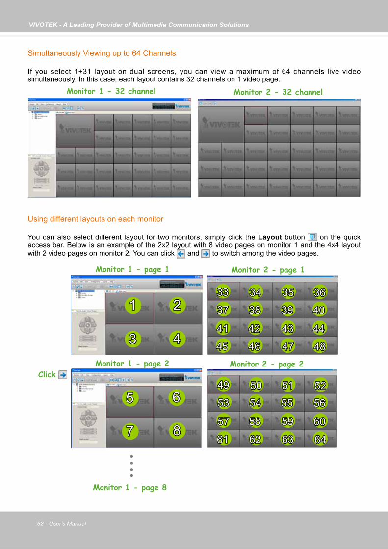
VIVOTEK - A Leading Provider of Multimedia Communication Solutions
82 - User's Manual
Simultaneously Viewing up to 64 Channels
If you select 1+31 layout on dual screens, you can view a maximum of 64 channels live video simultaneously. In this case, each layout contains 32 channels on 1 video page.
Using different layouts on each monitor
You can also select different layout for two monitors, simply click the Layout button on the quick access bar. Below is an example of the 2x2 layout with 8 video pages on monitor 1 and the 4x4 layout with 2 video pages on monitor 2. You can click and to switch among the video pages.
Monitor 2 - page 1Monitor 1 - page 1
Monitor 1 - page 2Click
1 2
3 4
5 6
7 8
34 35 3637 38 39 40
41 42 43 44
45 46 47 48
33
Monitor 1 - page 8
50 51 5253 54 55 56
57 58 59 60
61 62 63 64
49
Monitor 1 - 32 channel Monitor 2 - 32 channel
Monitor 2 - page 2
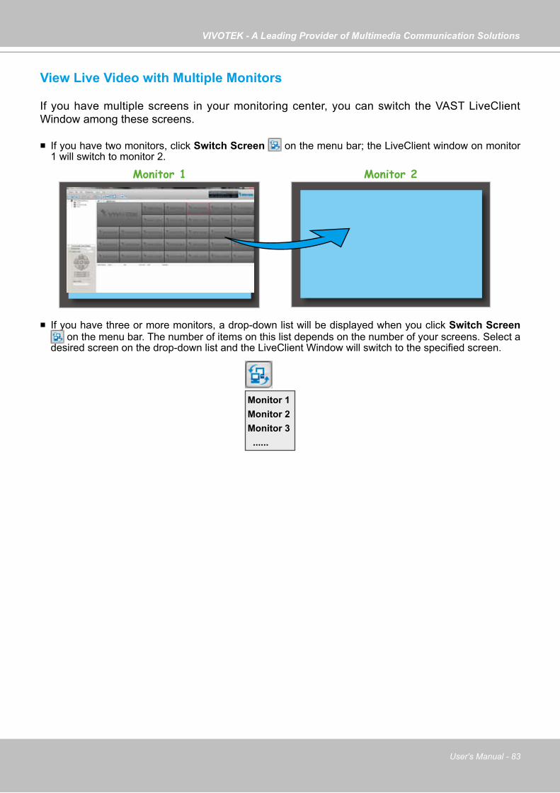
VIVOTEK - A Leading Provider of Multimedia Communication Solutions
User's Manual - 83
View Live Video with Multiple Monitors
If you have multiple screens in your monitoring center, you can switch the VAST LiveClient Window among these screens.
If you have two monitors, click Switch Screen on the menu bar; the LiveClient window on monitor 1 will switch to monitor 2.
If you have three or more monitors, a drop-down list will be displayed when you click Switch Screen on the menu bar. The number of items on this list depends on the number of your screens. Select a
desired screen on the drop-down list and the LiveClient Window will switch to the specified screen.
Monitor 1 Monitor 2
Monitor 1Monitor 2Monitor 3 ......
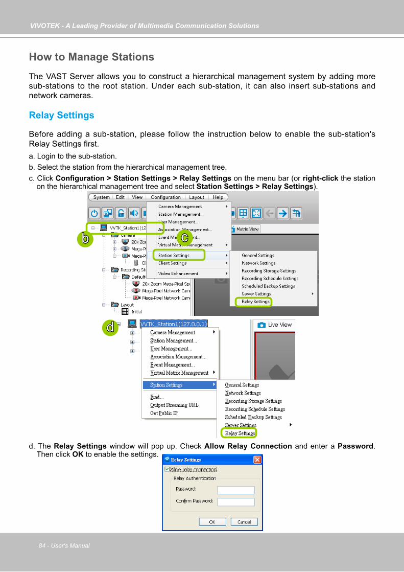
VIVOTEK - A Leading Provider of Multimedia Communication Solutions
84 - User's Manual
How to Manage StationsThe VAST Server allows you to construct a hierarchical management system by adding more sub-stations to the root station. Under each sub-station, it can also insert sub-stations and network cameras.
Relay Settings
Before adding a sub-station, please follow the instruction below to enable the sub-station's Relay Settings first.a. Login to the sub-station.b. Select the station from the hierarchical management tree.c. Click Configuration > Station Settings > Relay Settings on the menu bar (or right-click the station
on the hierarchical management tree and select Station Settings > Relay Settings).
d. The Relay Settings window will pop up. Check Allow Relay Connection and enter a Password. Then click OK to enable the settings.
b c
d
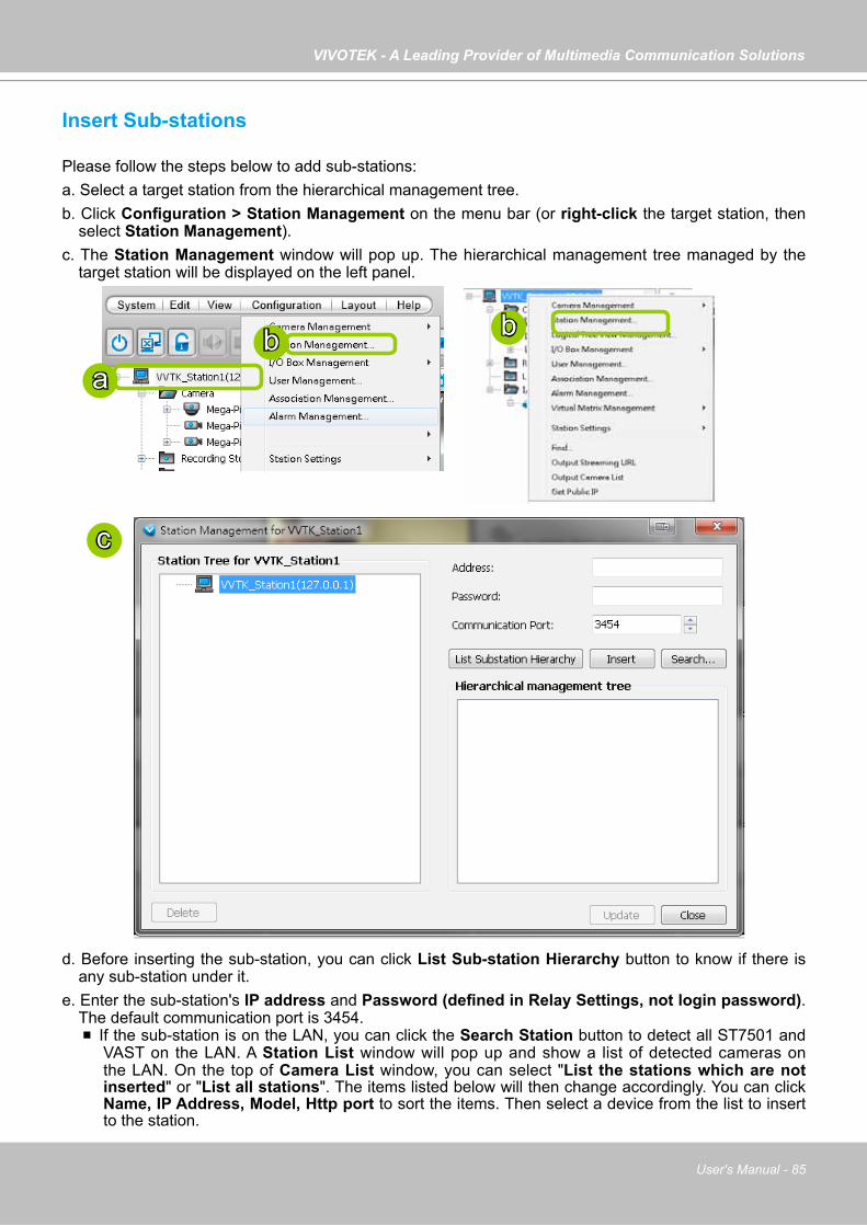
VIVOTEK - A Leading Provider of Multimedia Communication Solutions
User's Manual - 85
Insert Sub-stations
Please follow the steps below to add sub-stations:a. Select a target station from the hierarchical management tree.b. Click Configuration > Station Management on the menu bar (or right-click the target station, then
select Station Management).c. The Station Management window will pop up. The hierarchical management tree managed by the
target station will be displayed on the left panel.
d. Before inserting the sub-station, you can click List Sub-station Hierarchy button to know if there is any sub-station under it.
e. Enter the sub-station's IP address and Password (defined in Relay Settings, not login password). The default communication port is 3454. If the sub-station is on the LAN, you can click the Search Station button to detect all ST7501 and
VAST on the LAN. A Station List window will pop up and show a list of detected cameras on the LAN. On the top of Camera List window, you can select "List the stations which are not inserted" or "List all stations". The items listed below will then change accordingly. You can click Name, IP Address, Model, Http port to sort the items. Then select a device from the list to insert to the station.
ba
b
c
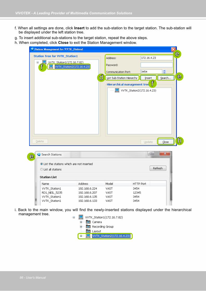
VIVOTEK - A Leading Provider of Multimedia Communication Solutions
86 - User's Manual
f. When all settings are done, click Insert to add the sub-station to the target station. The sub-station will be displayed under the left station tree.
g. To insert additional sub-stations to the target station, repeat the above steps.h. When completed, click Close to exit the Station Management window.
i. Back to the main window, you will find the newly-inserted stations displayed under the hierarchical management tree.
e
df
f
h
e
e

VIVOTEK - A Leading Provider of Multimedia Communication Solutions
User's Manual - 87
You can add VAST or free standard ST7501 as the sub-stations. The number of sub-stations can be added to the server depends on your key dongle. The VAST server will automatically detect the USB dongle installed on your host PC. Following is an illustration for two-level hierarchical architecture:
Please note that the following cyclic relay is not allowed.Server A Server C
Server B
Add server B as substation
Add server C as substation
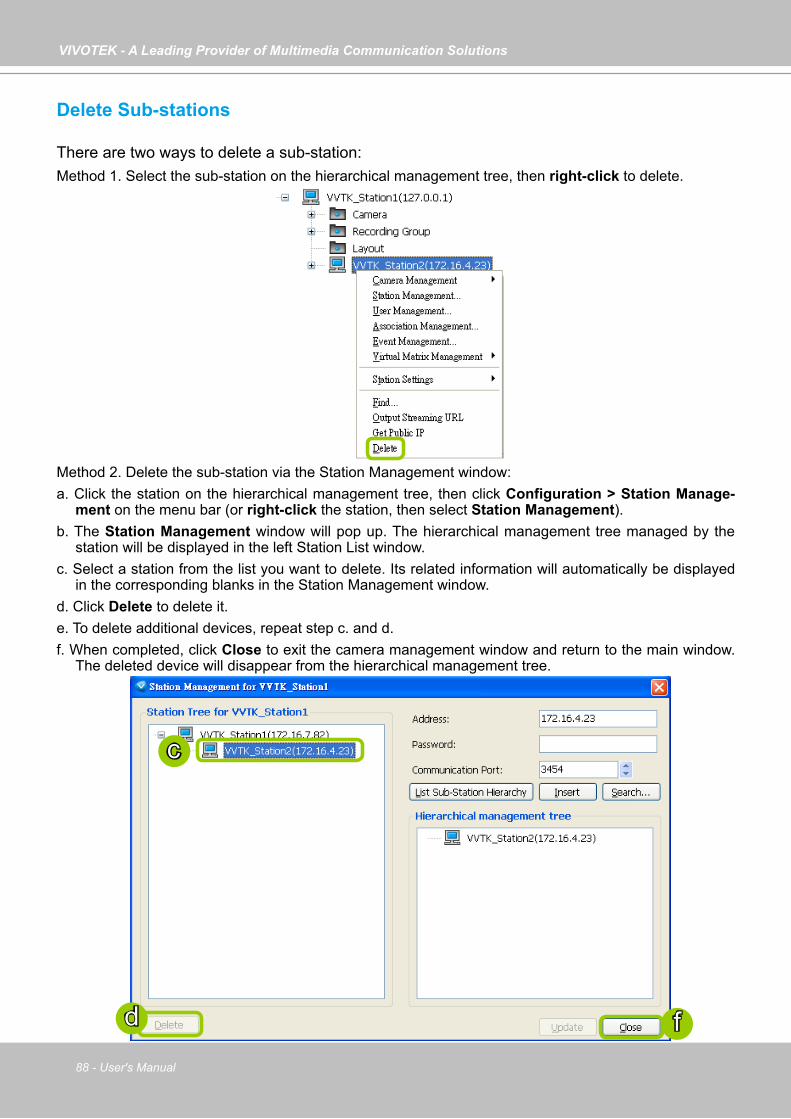
VIVOTEK - A Leading Provider of Multimedia Communication Solutions
88 - User's Manual
Delete Sub-stations
There are two ways to delete a sub-station:Method 1. Select the sub-station on the hierarchical management tree, then right-click to delete.
Method 2. Delete the sub-station via the Station Management window:a. Click the station on the hierarchical management tree, then click Configuration > Station Manage-
ment on the menu bar (or right-click the station, then select Station Management). b. The Station Management window will pop up. The hierarchical management tree managed by the
station will be displayed in the left Station List window.c. Select a station from the list you want to delete. Its related information will automatically be displayed
in the corresponding blanks in the Station Management window. d. Click Delete to delete it. e. To delete additional devices, repeat step c. and d.f. When completed, click Close to exit the camera management window and return to the main window.
The deleted device will disappear from the hierarchical management tree.
d
c
f

VIVOTEK - A Leading Provider of Multimedia Communication Solutions
User's Manual - 89
Update Stations
Please follow the steps below to update a station via Station Management window:a. Right-click the target device on the hierarchical management tree and click Station Management.b. The Station Management window will pop up. The hierarchical management tree managed by the
station will be displayed in the Station List window on the left.c. Select a station from the list you want to delete. Its related information will automatically be displayed
in the corresponding blanks in the Station Management window. d. When all settings are completed, click Update to enable the settings.
a
d
c
b
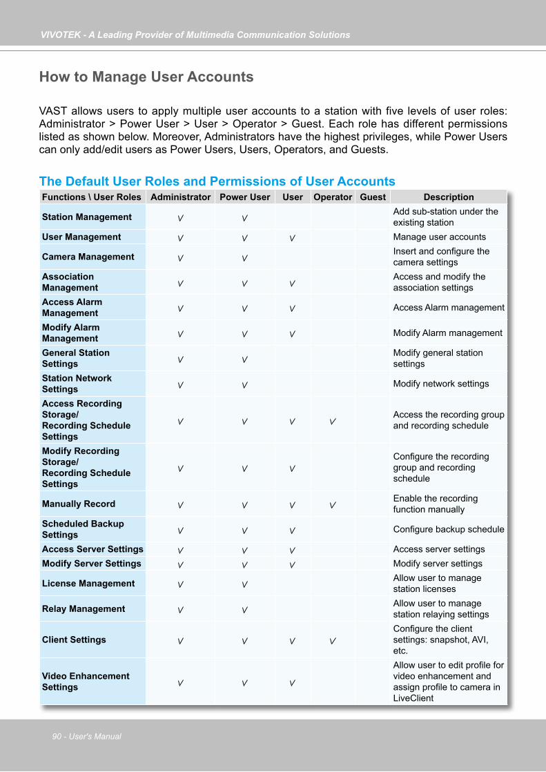
VIVOTEK - A Leading Provider of Multimedia Communication Solutions
90 - User's Manual
How to Manage User Accounts
VAST allows users to apply multiple user accounts to a station with five levels of user roles: Administrator > Power User > User > Operator > Guest. Each role has different permissions listed as shown below. Moreover, Administrators have the highest privileges, while Power Users can only add/edit users as Power Users, Users, Operators, and Guests.
The Default User Roles and Permissions of User AccountsFunctions \ User Roles Administrator Power User User Operator Guest Description
Station Management Add sub-station under the existing station
User Management Manage user accounts
Camera Management Insert and configure the camera settings
Association Management
Access and modify the association settings
Access Alarm Management Access Alarm management
Modify Alarm Management Modify Alarm management
General Station Settings
Modify general station settings
Station Network Settings Modify network settings
Access Recording Storage/Recording Schedule Settings
Access the recording group and recording schedule
Modify Recording Storage/Recording Schedule Settings
Configure the recording group and recording schedule
Manually Record Enable the recording function manually
Scheduled Backup Settings Configure backup schedule
Access Server Settings Access server settingsModify Server Settings Modify server settings
License Management Allow user to manage station licenses
Relay Management Allow user to manage station relaying settings
Client SettingsConfigure the client settings: snapshot, AVI, etc.
Video Enhancement Settings
Allow user to edit profile for video enhancement and assign profile to camera in LiveClient
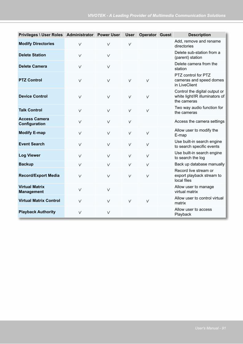
VIVOTEK - A Leading Provider of Multimedia Communication Solutions
User's Manual - 91
Privileges \ User Roles Administrator Power User User Operator Guest Description
Modify Directories Add, remove and rename directories
Delete Station Delete sub-station from a (parent) station
Delete Camera Delete camera from the station
PTZ ControlPTZ control for PTZ cameras and speed domes in LiveClient
Device ControlControl the digital output or white light/IR illuminators of the cameras
Talk Control Two way audio function for the cameras
Access Camera Configuration Access the camera settings
Modify E-map Allow user to modify the E-map
Event Search Use built-in search engine to search specific events
Log Viewer Use built-in search engine to search the log
Backup Back up database manually
Record/Export MediaRecord live stream or export playback stream to local files
Virtual Matrix Management
Allow user to manage virtual matrix
Virtual Matrix Control Allow user to control virtual matrix
Playback Authority Allow user to access Playback

VIVOTEK - A Leading Provider of Multimedia Communication Solutions
92 - User's Manual
Manage a User Account
Add a New User Account - Basic Accounta. Select the station from the hierarchical management tree.b. Click Configuration > User Management on the menu bar (or right-click the station, then select
User Management).
c. The User Management window will pop up. The user accounts under the station will be displayed under the left User List tree. Up to 1,021 users can be created (not including the default Admin and two internal communication accounts).
d. Enter the User Name, Password, and specify the User Role of this user.e. Click Add to add the user account to the station. It will be displayed under the User List.
cd
e
ba
b
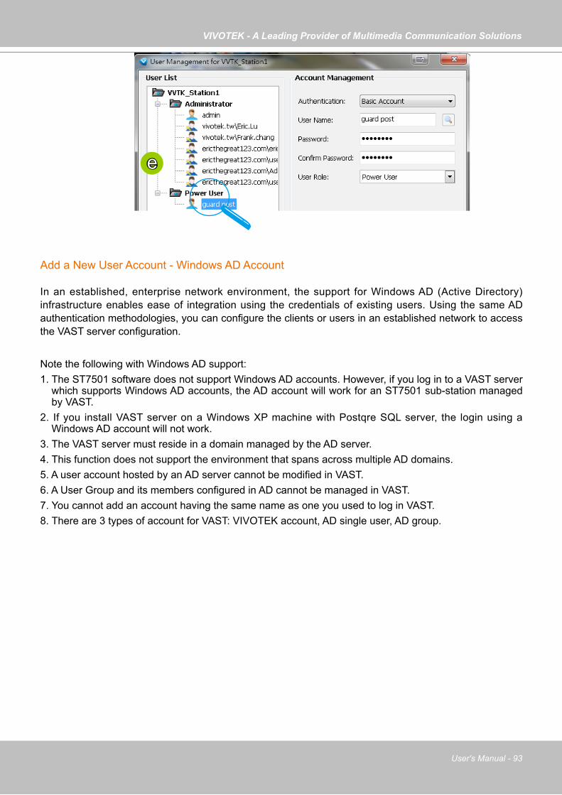
VIVOTEK - A Leading Provider of Multimedia Communication Solutions
User's Manual - 93
e
Add a New User Account - Windows AD Account
In an established, enterprise network environment, the support for Windows AD (Active Directory) infrastructure enables ease of integration using the credentials of existing users. Using the same AD authentication methodologies, you can configure the clients or users in an established network to access the VAST server configuration.
Note the following with Windows AD support:1. The ST7501 software does not support Windows AD accounts. However, if you log in to a VAST server
which supports Windows AD accounts, the AD account will work for an ST7501 sub-station managed by VAST.
2. If you install VAST server on a Windows XP machine with Postqre SQL server, the login using a Windows AD account will not work.
3. The VAST server must reside in a domain managed by the AD server. 4. This function does not support the environment that spans across multiple AD domains. 5. A user account hosted by an AD server cannot be modified in VAST. 6. A User Group and its members configured in AD cannot be managed in VAST. 7. You cannot add an account having the same name as one you used to log in VAST. 8. There are 3 types of account for VAST: VIVOTEK account, AD single user, AD group.
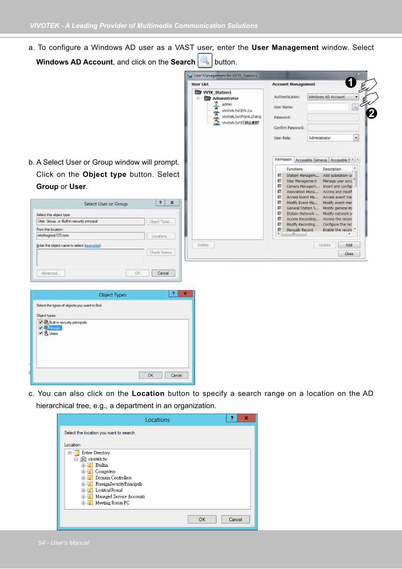
VIVOTEK - A Leading Provider of Multimedia Communication Solutions
94 - User's Manual
b. A Select User or Group window will prompt. Click on the Object type button. Select Group or User.
c. You can also click on the Location button to specify a search range on a location on the AD hierarchical tree, e.g., a department in an organization.
a. To configure a Windows AD user as a VAST user, enter the User Management window. Select
Windows AD Account, and click on the Search button.
1
2
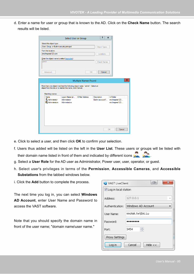
VIVOTEK - A Leading Provider of Multimedia Communication Solutions
User's Manual - 95
d. Enter a name for user or group that is known to the AD. Click on the Check Name button. The search results will be listed.
e. Click to select a user, and then click OK to confirm your selection.
f. Users thus added will be listed on the left in the User List. These users or groups will be listed with
their domain name listed in front of them and indicated by different icons .
g. Select a User Role for the AD user as Administrator, Power user, user, operator, or guest.
h. Select user's privileges in terms of the Permission, Accessible Cameras, and Accessible Substations from the tabbed windows below.
i. Click the Add button to complete the process.
The next time you log in, you can select Windows AD Account, enter User Name and Password to access the VAST software.
Note that you should specify the domain name in front of the user name; "domain name\user name."
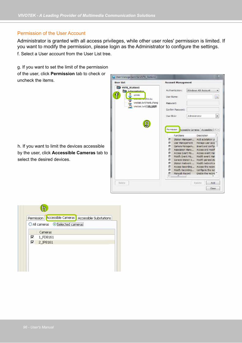
VIVOTEK - A Leading Provider of Multimedia Communication Solutions
96 - User's Manual
Permission of the User AccountAdministrator is granted with all access privileges, while other user roles' permission is limited. If you want to modify the permission, please login as the Administrator to configure the settings.f. Select a User account from the User List tree.
g. If you want to set the limit of the permission of the user, click Permission tab to check or uncheck the items.
h. If you want to limit the devices accessible by the user, click Accessible Cameras tab to select the desired devices.
h
f
g

VIVOTEK - A Leading Provider of Multimedia Communication Solutions
User's Manual - 97
i. If you want to set the access limit of the sub-station accessible by the user, click Accessible Substations tab to select the desired devices.
If you want to remove access permission mentioned above from the account, the user will not able to operate some functions listed in the following warning dialog.
j. When completed, click Update to enable the new settings.
Delete the User Accountk. Click Delete, a delete user dialog will pop up. Click OK to delete the user account.
If the Administrator modifies or deletes the User Account, that modified user might be kicked off from the station.
i
jk

VIVOTEK - A Leading Provider of Multimedia Communication Solutions
98 - User's Manual
How to Set up Association ManagementVAST LiveClient supports association management which allows the user to configure relative event trigger notifications of connected network devices. (E.g., DI/DO status on the hierarchical management tree, motion detection windows appear in the video cell, the event list in the event window)
Association Management
Please follow the steps below to configure assocation settings:a. Select the station from the hierarchical management tree.b. Click Configuration > Association Management on the menu bar (or right-click the station and
select Association Management).
c. The Association Management window will pop up. Check or uncheck the items and click Save to enable the settings. The items you've selected will also be displayed under the hierarchical management tree.
For example:
d. If you want to rename the DI device, select the DI item and click the Rename button. It will be very convenient for you to recognize the target DI device.
/ Digital input on / off
/ Digital output on / off
a
b
b
d
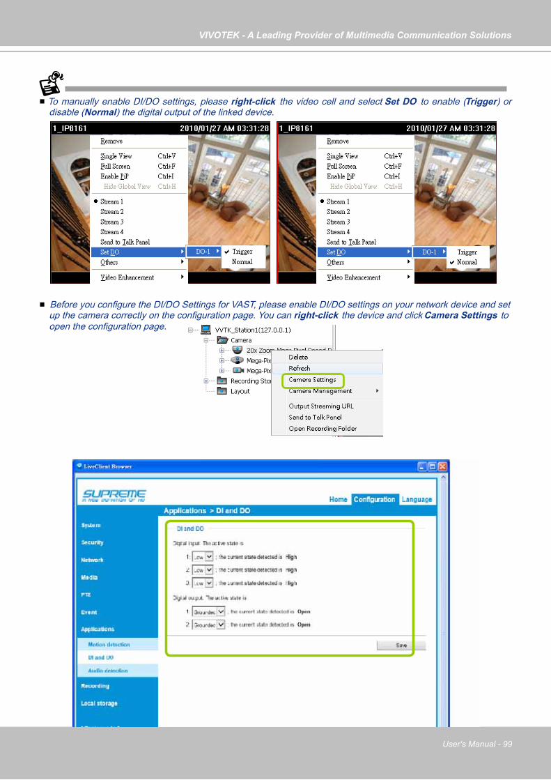
VIVOTEK - A Leading Provider of Multimedia Communication Solutions
User's Manual - 99
To manually enable DI/DO settings, please right-click the video cell and select Set DO to enable (Trigger) or disable (Normal) the digital output of the linked device.
Before you configure the DI/DO Settings for VAST, please enable DI/DO settings on your network device and set up the camera correctly on the configuration page. You can right-click the device and click Camera Settings to open the configuration page.
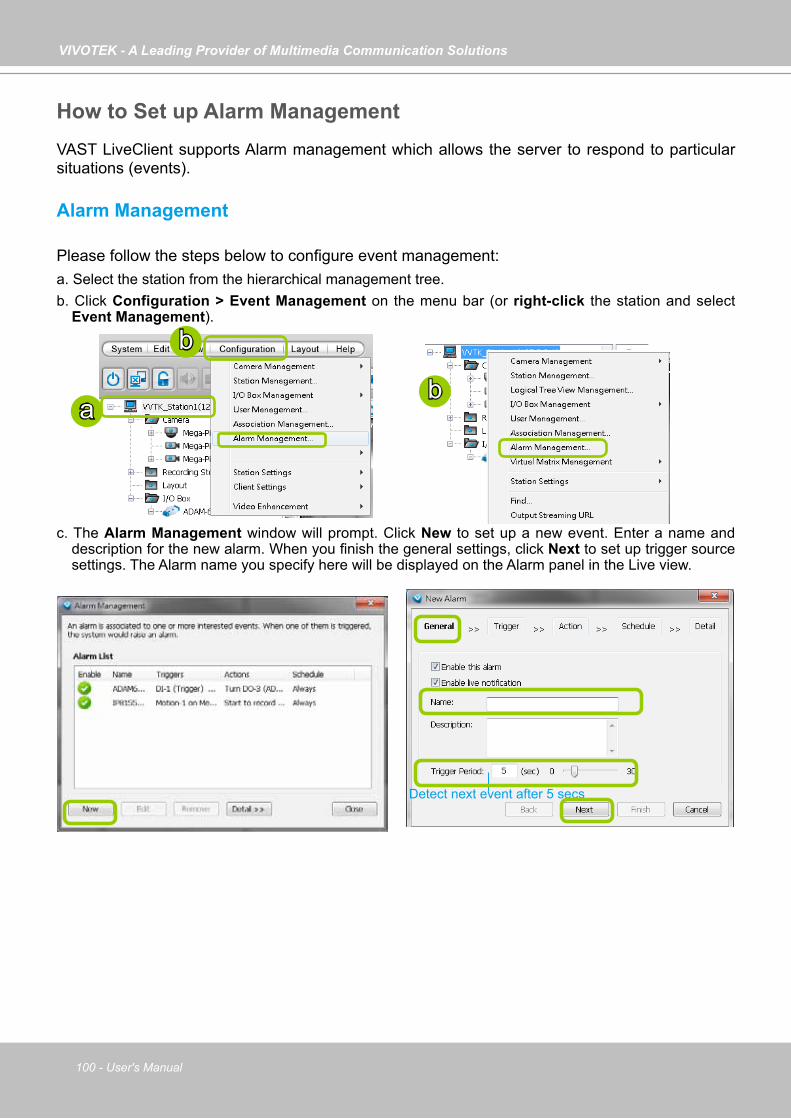
VIVOTEK - A Leading Provider of Multimedia Communication Solutions
100 - User's Manual
How to Set up Alarm ManagementVAST LiveClient supports Alarm management which allows the server to respond to particular situations (events).
Alarm Management
Please follow the steps below to configure event management:a. Select the station from the hierarchical management tree.b. Click Configuration > Event Management on the menu bar (or right-click the station and select
Event Management).
c. The Alarm Management window will prompt. Click New to set up a new event. Enter a name and description for the new alarm. When you finish the general settings, click Next to set up trigger source settings. The Alarm name you specify here will be displayed on the Alarm panel in the Live view.
a
b
b
Detect next event after 5 secs

VIVOTEK - A Leading Provider of Multimedia Communication Solutions
User's Manual - 101
d. Click Add to select the trigger source by Device or Trigger Type.
Note that Motion detection windows are separately configured using web consoles with each individual cameras. Open a web console with the camera to configure Motion detection windows.
The Storage Status includes: Storage connection status and storage capacity status on NVR systems.
Each individual motion detection window can be used as a triggering condition. The Line Crossing and Field Detection packages running on cameras also apply as triggers.
If you connect your DI/DO devices via an I/O module (I/O box), please refer to page 257, Appendix D Support for Digital I/O Modbus TCP Modules for details.
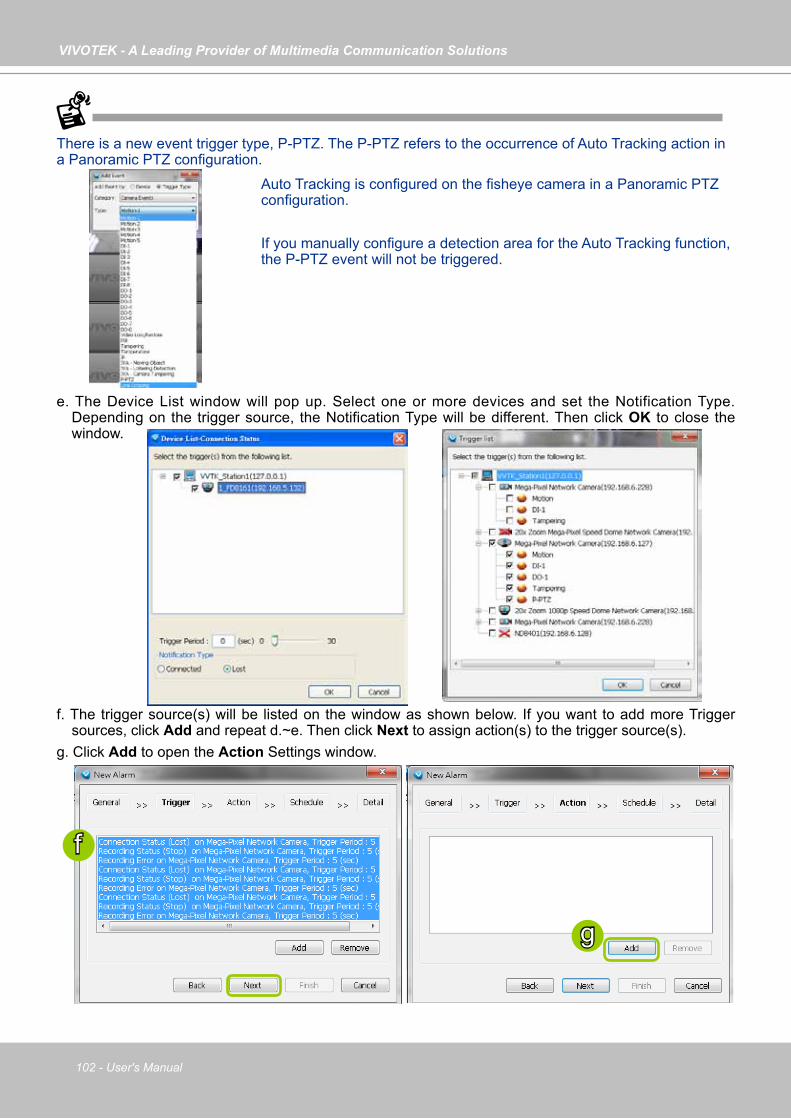
VIVOTEK - A Leading Provider of Multimedia Communication Solutions
102 - User's Manual
e. The Device List window will pop up. Select one or more devices and set the Notification Type. Depending on the trigger source, the Notification Type will be different. Then click OK to close the window.
f. The trigger source(s) will be listed on the window as shown below. If you want to add more Trigger sources, click Add and repeat d.~e. Then click Next to assign action(s) to the trigger source(s).
g. Click Add to open the Action Settings window.
f
g
There is a new event trigger type, P-PTZ. The P-PTZ refers to the occurrence of Auto Tracking action in a Panoramic PTZ configuration.
Auto Tracking is configured on the fisheye camera in a Panoramic PTZ configuration.
If you manually configure a detection area for the Auto Tracking function, the P-PTZ event will not be triggered.
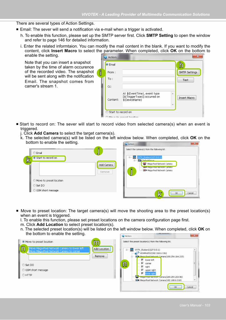
VIVOTEK - A Leading Provider of Multimedia Communication Solutions
User's Manual - 103
Start to record on: The sever will start to record video from selected camera(s) when an event is triggered. j. Click Add Camera to select the target camera(s).k. The selected camera(s) will be listed on the left window below. When completed, click OK on the
bottom to enable the setting.
Move to preset location: The target camera(s) will move the shooting area to the preset location(s) when an event is triggered. l. To enable this function, please set preset locations on the camera configuration page first. m. Click Add Location to select preset location(s). n. The selected preset location(s) will be listed on the left window below. When completed, click OK on
the bottom to enable the setting.
j
jk
mn
n
k
There are several types of Action Settings. Email: The sever will send a notification via e-mail when a trigger is activated.
h. To enable this function, please set up the SMTP server first. Click SMTP Setting to open the window and refer to page 146 for detailed information.
i. Enter the related informtaion. You can modify the mail content in the blank. If you want to modify the content, click Insert Macro to select the parameter. When completed, click OK on the bottom to enable the setting.
hi
Note that you can insert a snapshot taken by the time of alarm occurence
of the recorded video. The snapshot will be sent along with the notification Email. The snapshot comes from camer's stream 1.
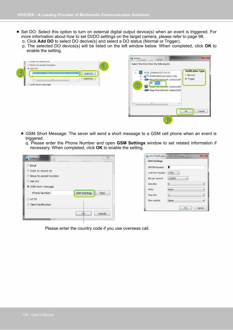
VIVOTEK - A Leading Provider of Multimedia Communication Solutions
104 - User's Manual
GSM Short Message: The sever will send a short message to a GSM cell phone when an event is triggered. q. Please enter the Phone Number and open GSM Settings window to set related information if
necessary. When completed, click OK to enable the setting.
Please enter the country code if you use overseas call.
Set DO: Select this option to turn on external digital output device(s) when an event is triggered. For more information about how to set DI/DO settings on the target camera, please refer to page 98. o. Click Add DO to select DO decive(s) and select a DO status (Normal or Trigger). p. The selected DO device(s) will be listed on the left window below. When completed, click OK to
enable the setting.
o
op
p
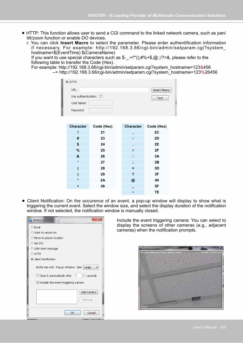
VIVOTEK - A Leading Provider of Multimedia Communication Solutions
User's Manual - 105
Client Notification: On the occurence of an event, a pop-up window will display to show what is triggering the current event. Select the window size, and select the display duration of the notification window. If not selected, the notification window is manually closed.
HTTP: This function allows user to send a CGI command to the linked network camera, such as pan/tilt/zoom function or enable DO devices. r. You can click Insert Macro to select the parameter. Please enter authentification information
if necessary. For example: http://192.168.3.66/cgi-bin/admin/setparam.cgi?system_hostname=$(EventTime) $(CameraName)If you want to use special characters such as $-_.+!*'(),#%+$,@:;/?=&, please refer to the following table to transfer the Code (Hex). For example: http://192.168.3.66/cgi-bin/admin/setparam.cgi?system_hostname=123&456 --> http://192.168.3.66/cgi-bin/admin/setparam.cgi?system_hostname=123%26456
Character Code (Hex)! 21# 23$ 24% 25& 26' 27( 28) 29* 2A+ 2B
Character Code (Hex), 2C- 2D. 2E/ 2F: 3A; 3B= 3D? 3F@ 40_ 5F~ 7E
Include the event triggering camera: You can select to display the screens of other cameras (e.g., adjacent cameras) when the notification prompts.
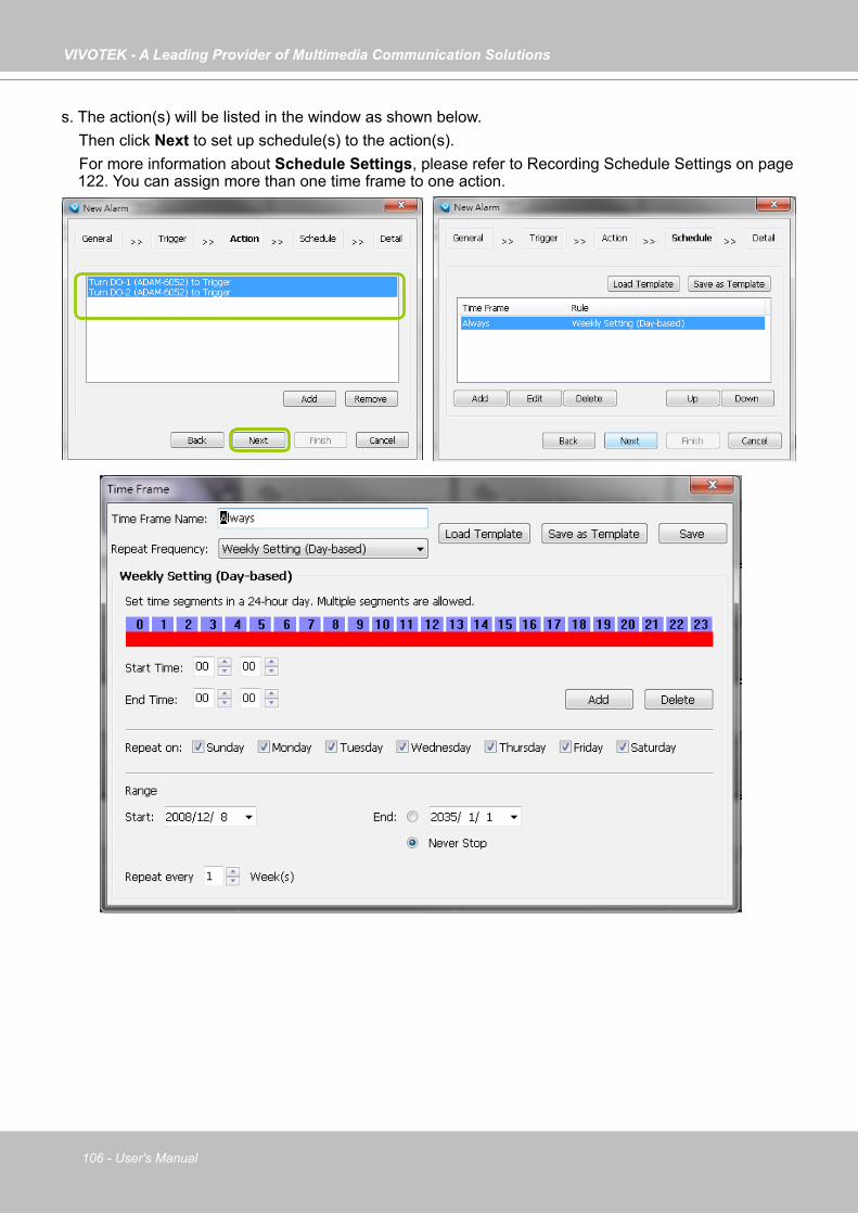
VIVOTEK - A Leading Provider of Multimedia Communication Solutions
106 - User's Manual
s. The action(s) will be listed in the window as shown below. Then click Next to set up schedule(s) to the action(s). For more information about Schedule Settings, please refer to Recording Schedule Settings on page
122. You can assign more than one time frame to one action.
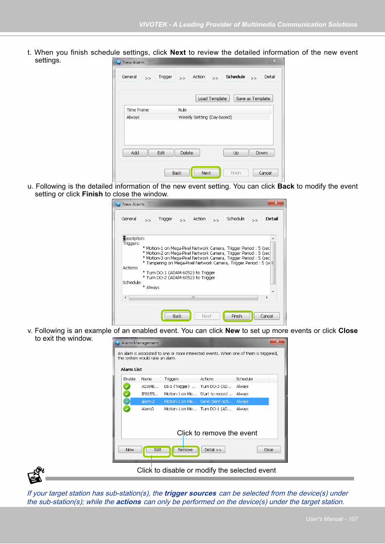
VIVOTEK - A Leading Provider of Multimedia Communication Solutions
User's Manual - 107
t. When you finish schedule settings, click Next to review the detailed information of the new event settings.
u. Following is the detailed information of the new event setting. You can click Back to modify the event setting or click Finish to close the window.
v. Following is an example of an enabled event. You can click New to set up more events or click Close to exit the window.
If your target station has sub-station(s), the trigger sources can be selected from the device(s) under the sub-station(s); while the actions can only be performed on the device(s) under the target station.
Click to disable or modify the selected event
Click to remove the event
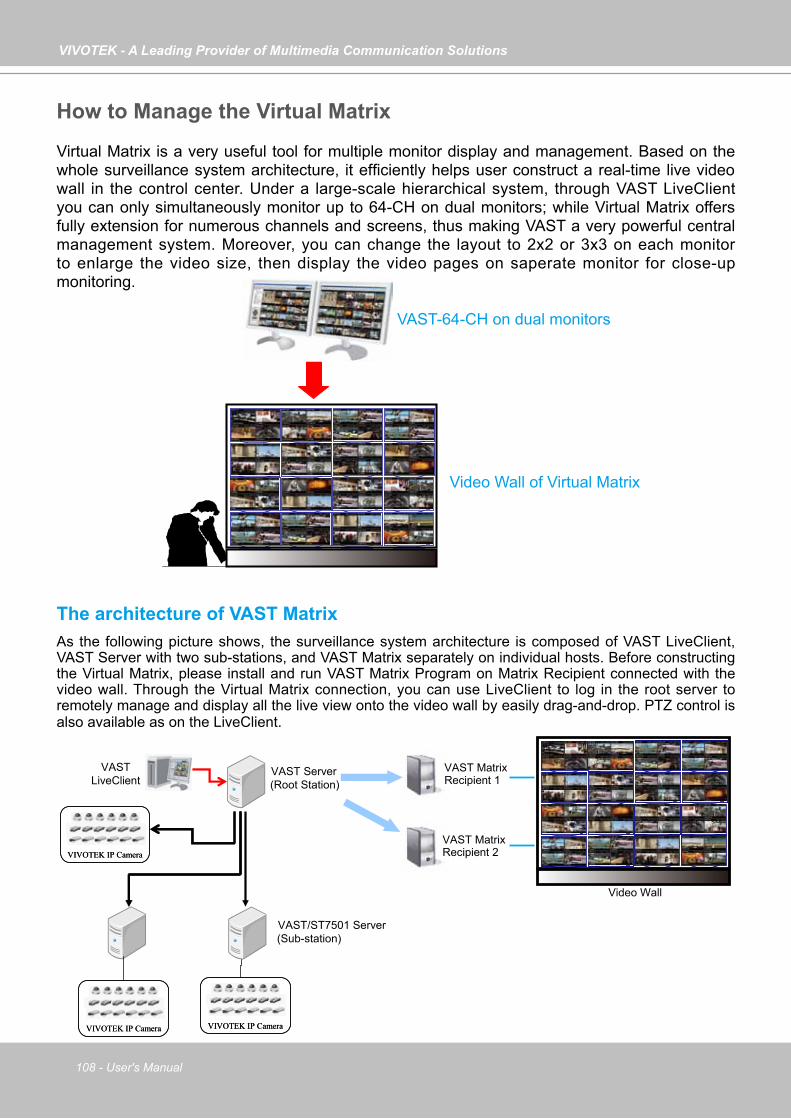
VIVOTEK - A Leading Provider of Multimedia Communication Solutions
108 - User's Manual
How to Manage the Virtual Matrix
Virtual Matrix is a very useful tool for multiple monitor display and management. Based on the whole surveillance system architecture, it efficiently helps user construct a real-time live video wall in the control center. Under a large-scale hierarchical system, through VAST LiveClient you can only simultaneously monitor up to 64-CH on dual monitors; while Virtual Matrix offers fully extension for numerous channels and screens, thus making VAST a very powerful central management system. Moreover, you can change the layout to 2x2 or 3x3 on each monitor to enlarge the video size, then display the video pages on saperate monitor for close-up monitoring.
The architecture of VAST MatrixAs the following picture shows, the surveillance system architecture is composed of VAST LiveClient, VAST Server with two sub-stations, and VAST Matrix separately on individual hosts. Before constructing the Virtual Matrix, please install and run VAST Matrix Program on Matrix Recipient connected with the video wall. Through the Virtual Matrix connection, you can use LiveClient to log in the root server to remotely manage and display all the live view onto the video wall by easily drag-and-drop. PTZ control is also available as on the LiveClient.
VAST-64-CH on dual monitors
Video Wall of Virtual Matrix
VAST Server(Root Station)
VASTLiveClient
VIVOTEK IP CameraVIVOTEK IP Camera
VIVOTEK IP CameraVIVOTEK IP CameraVIVOTEK IP CameraVIVOTEK IP Camera
VAST/ST7501 Server(Sub-station)
VAST Matrix Recipient 1
VAST Matrix Recipient 2
Video Wall
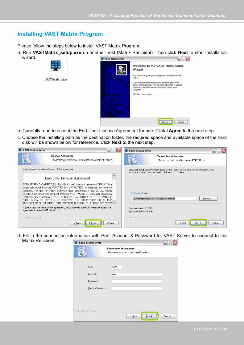
VIVOTEK - A Leading Provider of Multimedia Communication Solutions
User's Manual - 109
Installing VAST Matrix Program
Please follow the steps below to install VAST Matrix Program:a. Run VASTMatrix_setup.exe on another host (Matrix Recipient). Then click Next to start installation
wizard.
b. Carefully read to accept the End-User License Agreement for use. Click I Agree to the next step.c. Choose the installing path as the destination folder, the required space and available space of the hard
disk will be shown below for reference. Click Next to the next step.
d. Fill in the connection information with Port, Account & Password for VAST Server to connect to the Matrix Recipient.
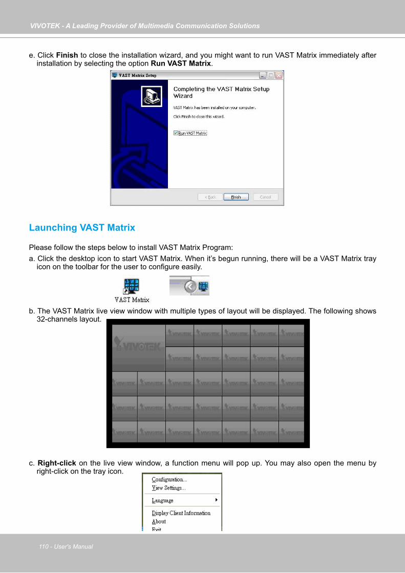
VIVOTEK - A Leading Provider of Multimedia Communication Solutions
110 - User's Manual
e. Click Finish to close the installation wizard, and you might want to run VAST Matrix immediately after installation by selecting the option Run VAST Matrix.
Launching VAST Matrix
Please follow the steps below to install VAST Matrix Program:a. Click the desktop icon to start VAST Matrix. When it’s begun running, there will be a VAST Matrix tray
icon on the toolbar for the user to configure easily.
b. The VAST Matrix live view window with multiple types of layout will be displayed. The following shows 32-channels layout.
c. Right-click on the live view window, a function menu will pop up. You may also open the menu by right-click on the tray icon.
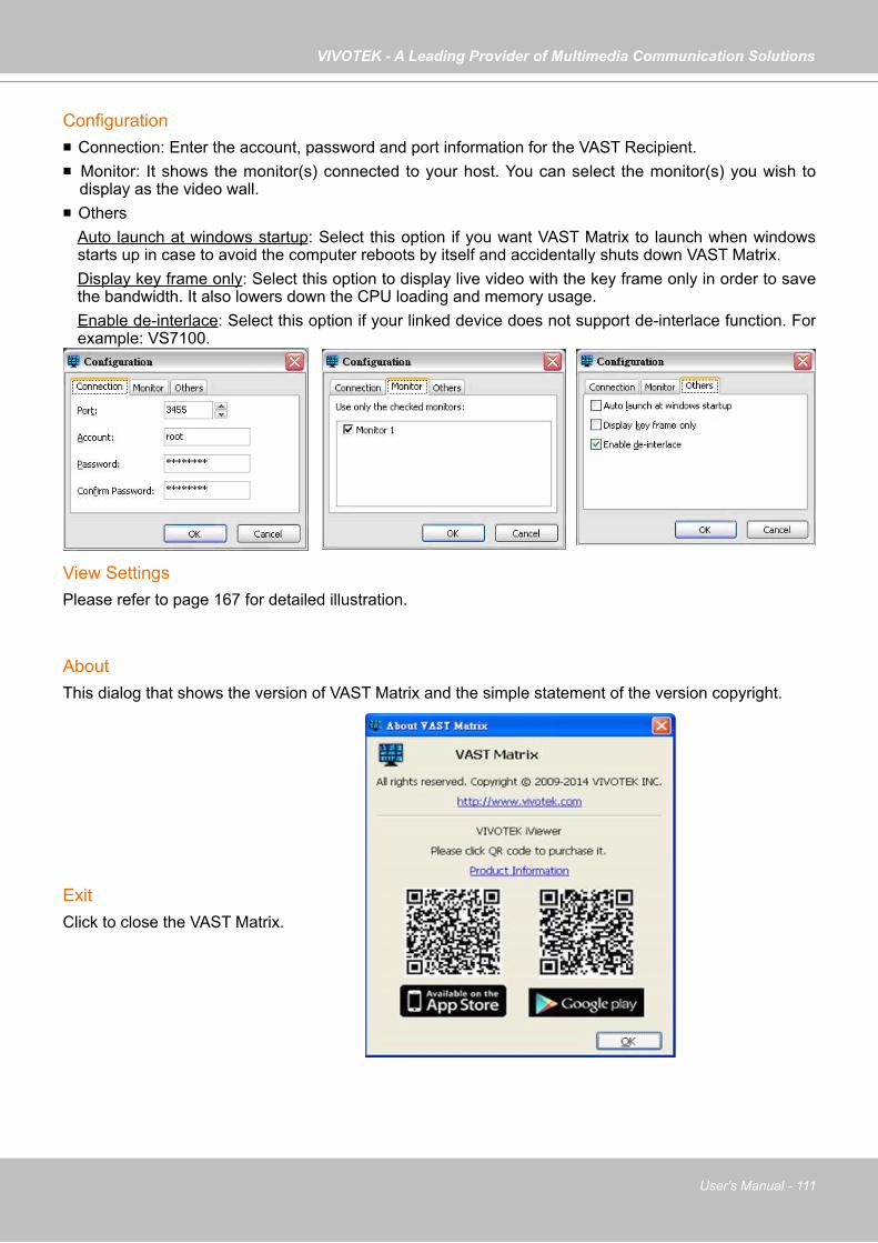
VIVOTEK - A Leading Provider of Multimedia Communication Solutions
User's Manual - 111
Configuration Connection: Enter the account, password and port information for the VAST Recipient. Monitor: It shows the monitor(s) connected to your host. You can select the monitor(s) you wish to
display as the video wall. Others
Auto launch at windows startup: Select this option if you want VAST Matrix to launch when windows starts up in case to avoid the computer reboots by itself and accidentally shuts down VAST Matrix. Display key frame only: Select this option to display live video with the key frame only in order to save the bandwidth. It also lowers down the CPU loading and memory usage. Enable de-interlace: Select this option if your linked device does not support de-interlace function. For example: VS7100.
View SettingsPlease refer to page 167 for detailed illustration.
AboutThis dialog that shows the version of VAST Matrix and the simple statement of the version copyright.
ExitClick to close the VAST Matrix.

VIVOTEK - A Leading Provider of Multimedia Communication Solutions
112 - User's Manual
VAST Matrix Management
Once the VAST Matrix Program is setup completely, the next step is to connect the VAST Server with VAST Matrix Recipient(s). Use LiveClient to log in VAST Server, then click Configuration > Virtual Matrix Management to configure Matrix Management and Matrix View Settings.
Matrix Management SettingsPlease follow the steps to set up VAST Matrix Recipient(s):a. Click Configuration > Virtual Matrix Management > Matrix Management to open the Matrix
Management window.b. Manually enter the Matrix Recipient Info as previous settings, or you click the search button to
search for the Matrix Recipient(s) on the LAN.c. When the information of the target recipient is filled in, you can use the detect button to confirm if
the filled information is correct. d. Click Add, then the recipient will be displayed on the Matrix Recipients list window.
e. Click Edit display settings to set up the viewing interface for the monitors (video wall) connected to the Matrix Recipient host.
b
c
d
d
e
The Matrix View display is capable of executing rotation. The default interval time is set at 10 seconds.
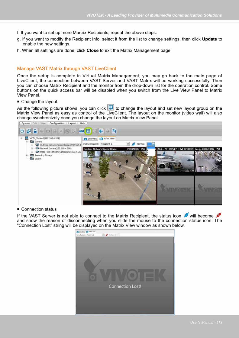
VIVOTEK - A Leading Provider of Multimedia Communication Solutions
User's Manual - 113
f. If you want to set up more Martrix Recipients, repeat the above steps.g. If you want to modify the Recipient Info, select it from the list to change settings, then click Update to
enable the new settings.h. When all settings are done, click Close to exit the Matrix Management page.
Manage VAST Matrix through VAST LiveClientOnce the setup is complete in Virtual Matrix Management, you may go back to the main page of LiveClient, the connection between VAST Server and VAST Matrix will be working successfully. Then you can choose Matrix Recipient and the monitor from the drop-down list for the operation control. Some buttons on the quick access bar will be disabled when you switch from the Live View Panel to Matrix View Panel. Change the layoutAs the following picture shows, you can click to change the layout and set new layout group on the Matrix View Panel as easy as control of the LiveClient. The layout on the monitor (video wall) will also change synchronizely once you change the layout on Matrix View Panel.
Connection statusIf the VAST Server is not able to connect to the Matrix Recipient, the status icon will become and show the reason of disconnecting when you slide the mouse to the connection status icon. The "Connection Lost" string will be displayed on the Matrix View window as shown below.

VIVOTEK - A Leading Provider of Multimedia Communication Solutions
114 - User's Manual
RotationVAST Matrix is capable of executing rotation by clicking . You can even select another layout group on the Matrix View window without stopping the rotation. If you want to adjust the rotation interval time, please refer to Edit display settings on page 112 for adjusting.
PTZ VAST Matrix currently does not support PTZ control.
Matrix View Menu Right-click on the window to open the menu. Remove: Remove the channel from VAST Matrix. Stream 1 ~ 4: Switch the camera stream between 1 ~ 4.
Remove All ConnectionsIt’s capable of removing all connections from VAST Matrix once by clicking on button.
Matrix View Settings
Click Configuration > Virtual Matrix Management > Matrix View Settings to open the window.
Media SourceYou can choose the path of media source from camera directly or the CMS server to display on Matrix View.
Display SettingsYou can choose the display frame rate as full frame rate or key frame only.
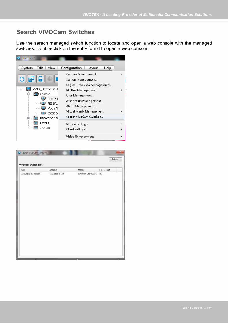
VIVOTEK - A Leading Provider of Multimedia Communication Solutions
User's Manual - 115
Search VIVOCam SwitchesUse the serach managed switch function to locate and open a web console with the managed switches. Double-click on the entry found to open a web console.

VIVOTEK - A Leading Provider of Multimedia Communication Solutions
116 - User's Manual
How to Configure the Station General Settings
Select the target station from the hierarchical management tree, then click Configuration > Station Settings > General Settings on the menu bar (or right-click the station on the hierarchical management tree and select Station Settings > General Settings). The Station General Settings window will pop up.
Server SettingsIn this section, you can modify the Station Name.
Log SettingsIn this section, you can set up Log Settings for the station. The VAST server allows user to search for the recorded log through VAST Playback. For more information, please refer to How to Search Logs on page 237. Log level: Select High (only record high-level logs),
Normal (record high-level and normal-level logs), Low (record all logs). For detailed information about log levels, please refer to page 238.
Reserve Time: Enter the time interval that you want to reserve the log record. The maximum value is 365 days.

VIVOTEK - A Leading Provider of Multimedia Communication Solutions
User's Manual - 117
How to Configure Station Network Settings
Select the target station from the hierarchical management tree, then click Configuration > Station Settings > Network Settings on the menu bar (or right-click the station on the hierarchical management tree and select Station Settings > Network Settings). The Network Settings window will pop up.
Port Settings Server port: The default server port is set to 3454. If you change
the server port, please enter the new value while logging the LiveClient next time.
RTSP port: The RTSP (Real-Time Streaming Protocol) controls the delivery of streaming media. By default, the port number is set to 4543.
UPnP Settings Enable UPnP port forwarding: For client to access the VAST Server
from the Internet, select this option to allow the server to open ports on the router automatically so the video streams can be sent out from a LAN. To utilize of this feature, make sure that your router supports UPnPTM and it is activated.
Enable UPnP presentation: If you select this option, shortcuts to VAST Server will be listed in My Network Places.
Proxy SettingsIn this section, you can enable, modify, or cancel Proxy Settings for VAST Server if your network devices are set up under a proxy.
Web Access SettingsUser can access VAST LiveClient and Playback via Internet web browser (http://IP address:3454). For local host --> http://127.0.0.1:3454. See page 93 for Windows AD account information.

VIVOTEK - A Leading Provider of Multimedia Communication Solutions
118 - User's Manual
How to Edit Recording Groups
By default, all devices are assigned to the default recording group. You can manually remove a device from the default recording group. However, only those devices which belong to a recording group can produce recorded media files.
Another purpose of setting recording group is that you can divide all the managed devices into several recording groups, and for each recording group, you can assign several hard-disks (with recording paths) to store media data. The live media data will be stored in the first assigned hard-disk initially, and when the available space of the first hard disk reaches the preset reserved space limit, the media data will be stored in the second disk and so on. If the available space of the last disk reaches the reserved space limit, the recorded files in the first disk will be overwritten with the new media data. This procedure is called "Cyclic Recording".
Recording Storage Settings
Please follow the steps below to set up recording groups for a station:a. Select the target station from the hierarchical management tree.b. Click Configuration > Station Settings > Recording Storage Settings on the menu bar (or right-
click the station on the hierarchical management tree and select Station Settings > Recording Storage Settings). You can also right-click DefaultGroup under the station and click Recording Storage Settings since all devices are assigned to the Default Recording Group by default settings.
c. The Recording Storage Settings window will pop up.
b
a
b
b

VIVOTEK - A Leading Provider of Multimedia Communication Solutions
User's Manual - 119
Default Storage Group SettingsThe following example shows the default storage group settings. You can click Rename to modify the group name or click Delete to remove the default settings.
d. The default recording path is D:\Recording. The total space and free space of the disk is shown on the right for reference.
e. Add Local Path: Click to add another recording path on your local computer. A Select Path dialog will pop up as shown below. When all settings are complete, click OK to enable the settings, or click Cancel to discard the settings. The default reserved space is 10% of the disk volume.
f. Add Network Path: Click to add a networked storage for recorded data. Please refer to page 145 for detailed information about how to add a new network storage server. Then double-click the Path to assign a specific folder as a new recording path.
d
e
Click those buttons to modify the file folder under D:\
f
Note that the reserved space is the comparatively small amount of storage space saved for data transaction during recording cycles. The reserved space is not the storage space configured for video recording.
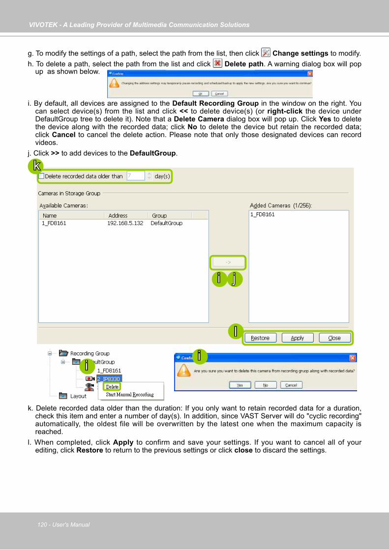
VIVOTEK - A Leading Provider of Multimedia Communication Solutions
120 - User's Manual
g. To modify the settings of a path, select the path from the list, then click Change settings to modify.h. To delete a path, select the path from the list and click Delete path. A warning dialog box will pop
up as shown below.
i. By default, all devices are assigned to the Default Recording Group in the window on the right. You can select device(s) from the list and click << to delete device(s) (or right-click the device under DefaultGroup tree to delete it). Note that a Delete Camera dialog box will pop up. Click Yes to delete the device along with the recorded data; click No to delete the device but retain the recorded data; click Cancel to cancel the delete action. Please note that only those designated devices can record videos.
j. Click >> to add devices to the DefaultGroup.
k. Delete recorded data older than the duration: If you only want to retain recorded data for a duration, check this item and enter a number of day(s). In addition, since VAST Server will do "cyclic recording" automatically, the oldest file will be overwritten by the latest one when the maximum capacity is reached.
l. When completed, click Apply to confirm and save your settings. If you want to cancel all of your editing, click Restore to return to the previous settings or click close to discard the settings.
i
i j
i
k
l

VIVOTEK - A Leading Provider of Multimedia Communication Solutions
User's Manual - 121
Add New Recording Group(s)If you want to add a new recording group, click Add to give a name to the new recording group, which will be displayed on the drop-down list.The following is an example of recording group list.
Please refer to the following limits when you set up recording group(s): The maximum number of devices in a recording group is 64-CH. Please refer to the system requirements of the
software. One recording group can be assigned with several recording paths and do cylic recording; while one recording
path should only be assigned to one recording group.

VIVOTEK - A Leading Provider of Multimedia Communication Solutions
122 - User's Manual
How to Edit Recording SchedulesAfter editing recording storage settings, you can begin to edit recording schedules for the devices in a recording group. By default, all devices are assigned to the default recording schedule (Please refer to the default time frame settings on page 126). Therefore, once you insert a device to the station, the VAST Server will begin to record live video according to the default recording schedule. You can also manually remove a device from the default recording schedule. Please note that you cannot assign recording schedules to those devices which have been deleted from a recording group.
The following is an illustration of a set of recording schedules, which are composed of several time frames. Each time frame has its own time segments, period of time, repeat interval, and recording mode. You can create different recording schedules with simple or complex time frames based on your needs.
In addition, you can arrange the priority of each time frame according to its importance. The recording schedule with the highest priority will be applied first. This capability is very useful because you can specify a new time frame with the highest priority temporarily without modifying the other time frames.
Features of the recording schedules: Each device can be assigned to only one recording schedule. Each recording schedule may contain many time frames. Each time frame has its own repeat frequency and recording mode.
To save time editing recording schedules and time-frames, we also provide a useful template function to save your time on schedules/time-frames settings. That is, you can save a specified schedule and download it as a template for future use or upload a well-arranged schedule template designed by others.
Please note that after you save the recording settings in the server, the recording schedule will begin automatically according to your settings.
Router
Time Frame a
Recording Schedule 1
Time Frame b
Time Frame n
Time Frame y
Recording Schedule N
Time Frame z
Devices in Recording Group
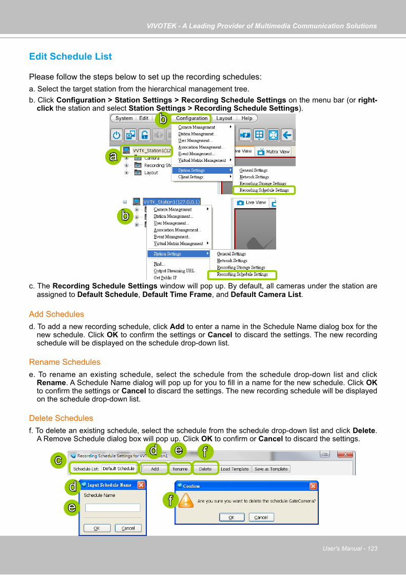
VIVOTEK - A Leading Provider of Multimedia Communication Solutions
User's Manual - 123
Edit Schedule List
Please follow the steps below to set up the recording schedules:a. Select the target station from the hierarchical management tree.b. Click Configuration > Station Settings > Recording Schedule Settings on the menu bar (or right-
click the station and select Station Settings > Recording Schedule Settings).
c. The Recording Schedule Settings window will pop up. By default, all cameras under the station are assigned to Default Schedule, Default Time Frame, and Default Camera List.
Add Schedulesd. To add a new recording schedule, click Add to enter a name in the Schedule Name dialog box for the
new schedule. Click OK to confirm the settings or Cancel to discard the settings. The new recording schedule will be displayed on the schedule drop-down list.
Rename Schedulese. To rename an existing schedule, select the schedule from the schedule drop-down list and click
Rename. A Schedule Name dialog will pop up for you to fill in a name for the new schedule. Click OK to confirm the settings or Cancel to discard the settings. The new recording schedule will be displayed on the schedule drop-down list.
Delete Schedulesf. To delete an existing schedule, select the schedule from the schedule drop-down list and click Delete.
A Remove Schedule dialog box will pop up. Click OK to confirm or Cancel to discard the settings.
e fd
ed
f
a
b
c
b

VIVOTEK - A Leading Provider of Multimedia Communication Solutions
124 - User's Manual
Load/Save Schedule Templatesg. If you have a schedule template with time frame settings, you can upload it to simplify the editing of
the schedule. Click Load Template, and a Load File dialog box will pop up. Select the template file and click Open to load.
h. If you want to save a schedule as a template for future use, select the schedule from the schedule drop-down list and click Save as Template. A Save File dialog box will pop up for you to save the template file.
g
h
hg

VIVOTEK - A Leading Provider of Multimedia Communication Solutions
User's Manual - 125
Edit Camera List
Please follow the steps below to assign a device to a recording schedule:a. Select a recording schedule on the schedule drop-down list.b. By default, all devices under the station are assigned to the Default Schedule.c. Click << to remove devices from the Default Schedule. Click >> to add devices to the Default
Schedule. d. Click Apply to confirm or Close to discard the settings.
If you add a Network Device that does not belong to any Recording Group, a warning dialog will pop up as shown below. For more information about how to set up Recording Group(s), please refer to Recording Group Settings on page 118.
b
c
f
a
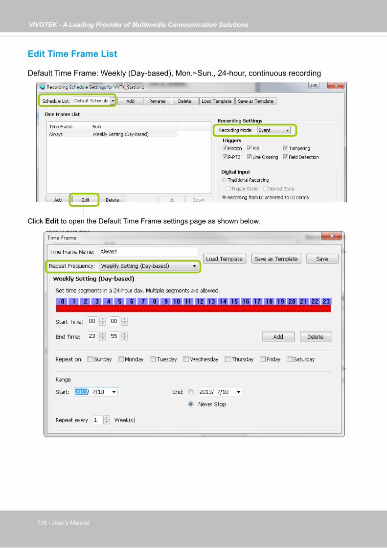
VIVOTEK - A Leading Provider of Multimedia Communication Solutions
126 - User's Manual
Edit Time Frame List
Default Time Frame: Weekly (Day-based), Mon.~Sun., 24-hour, continuous recording
Click Edit to open the Default Time Frame settings page as shown below.
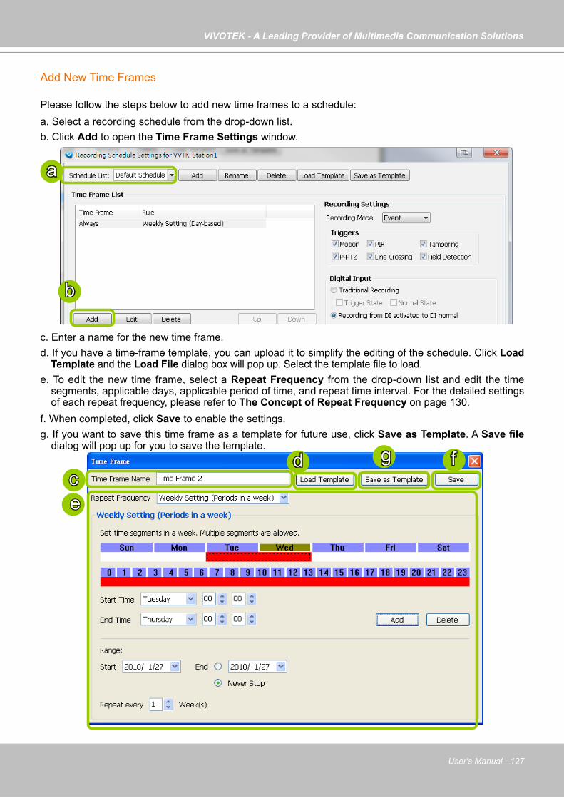
VIVOTEK - A Leading Provider of Multimedia Communication Solutions
User's Manual - 127
Add New Time Frames
Please follow the steps below to add new time frames to a schedule:a. Select a recording schedule from the drop-down list.b. Click Add to open the Time Frame Settings window.
c. Enter a name for the new time frame.d. If you have a time-frame template, you can upload it to simplify the editing of the schedule. Click Load
Template and the Load File dialog box will pop up. Select the template file to load. e. To edit the new time frame, select a Repeat Frequency from the drop-down list and edit the time
segments, applicable days, applicable period of time, and repeat time interval. For the detailed settings of each repeat frequency, please refer to The Concept of Repeat Frequency on page 130.
f. When completed, click Save to enable the settings.g. If you want to save this time frame as a template for future use, click Save as Template. A Save file
dialog will pop up for you to save the template.
a
b
cd fg
e

VIVOTEK - A Leading Provider of Multimedia Communication Solutions
128 - User's Manual
h. If you want to add additional time frames to the schedule, repeat the steps above. i. Close the window when you finish the time frame settings.j. Back to the Recording Schedule Settings window, the new time frame will be displayed on the Time
Frame List.k. If you want to edit an existing time frame, select if from the Time Frame List and click Edit to set up.l. If you want to delete an existing time frame, select if from the Time Frame List and click Delete.m. If you want to change the priority of a time frame, select it from the Time Frame List and click Up or
Down to shift its position. The time frame on the top of the list has the highest priority.
Recording Settingsn. Select one of the following Recording Modes for the time frame: None: No recording action. Continuous: 24-hours continuous recording. If you want to enable Activity Adaptive Streaming,
please refer to page 121 for detailed illutration. Event: The server will start to record only when an event is triggered. The recording time length
depends on the settings in Recording Storage Settings. The default time length is 20 seconds (10s pre-event time plus 10s post-event time). Please refer to page 120 for more information. For more information about event catagories, please refer to page 231 for detailed information.
o. Select Trigger Source(s): Motion Detection, Line Crossing, Field Detection, PIR, Tampering Detection, and P-PTZ (Auto Tracking).
p. Digital Input: See next page for more information.
j
n
m
q
k l
o
p

VIVOTEK - A Leading Provider of Multimedia Communication Solutions
User's Manual - 129
q. Click Apply to confirm the settings. Then close the window when you finish the recording schedule settings.
The Digital Input signal triggers can be configured as follows:1. Traditional Recording: can be triggered when the DI enters the Trigger State or the Normal
State. If thus configured, the recording task will end when the post-event recording time is reached.
2. The recording starts when DI is triggered, and will end when the DI signal returns to Normal.3. The recording starts when DI is Normal, and will end when the DI signal returns to Triggered. An example for the configuration can be: the recording starts when a door is opened (DI triggered), and the recording stops when the door is closed (DI returns to normal).
When connected, a camera's Digital input signal is automatically detected as pulled-high or pulled-low. Users should then designate the current state as Normal or Trigger. The configuration page is found in Configuration > Application > Digital Input on a web console.

VIVOTEK - A Leading Provider of Multimedia Communication Solutions
130 - User's Manual
The following diagrams show the frame rate variation of two recording modes:1. Continuous recording + Activity adaptive recording (helps save bandwidth and storage)
2. Event recording
The Concept of Repeat Frequency
VAST offers the following types of repeat frequency. The definition of each type is listed in the following table:Repeat Frequency Discription
Daily Setting Specify arbitrary time segments within a day, Repeat the segments every N days in the specified period of time.
Weekly Setting (Day-based)(Default Time Frame)
Specify arbitrary time segments within a day, Apply only on selected days of a week, Repeat the segments every N weeks during the specified period of time.
Weekly Setting (Periods in a week) Specify arbitrary time segments within a week, Repeat the segments every N weeks during the specified period of time.
Monthly Setting (Day-based) Specify arbitrary time segments within a day, Apply only on selected days of a month, Repeat the segments every N months during the specified period of time.
Yearly Setting (Day-based) Specify arbitrary time segments within a day, Apply only on selected days of a year, Repeat the segments every N years during the specified period of time.
Time
Bandwidth
Continuous Recording I frame ---> Full frame rate ---> I frame
Event Recording
Time
Bandwidth
No recording data ---> Full frame rate ---> No recording data

VIVOTEK - A Leading Provider of Multimedia Communication Solutions
User's Manual - 131
Repeat Frequency: Daily Setting
To set up daily repeat frequency, please configure the following items: Daily time segments, applicable period of time, and repeat time interval.
Set up daily time segments
You can specify several time segments within a day. The numbers 0~23 on the hourly timeline control bar (the purple rectangles) represent the 24 hours in a day.
There are two ways to define time segments: one is to use the computer mouse to manipulate the timeline control bars; the other is to fill in the precise start and end time values in the corresponding fields.
Add time segments: Choose either step 1 or step 2 to set up1. Use the mouse to drag the timeline bars:
a. Left-click the daily timeline control bar (the purple rectangles) and drag the mouse. b. The corresponding time segment will also appear in the Start Time and End Time fields. Click Add,
then the red timeline bars representing new time segments will appear as shown below. You can drag multiple time segments within a day. In the following illustration, the yellow arrows show the dragging direction of the mouse. You can drag from left to right or the opposite.
Daily time segments *You can drag the daily timeline bar for more than one time segment per day.
Applicable period of time
Repeat time interval
Daily timeline control bar

VIVOTEK - A Leading Provider of Multimedia Communication Solutions
132 - User's Manual
2. Fill in the precise Start Time and End Time: a. Directly enter the value in the Start Time and End Time fields, then click Add.b. The corresponding red timeline bar will automatically appear as shown below.
Delete time segments: Choose either step 1 or step 2 to set up1. Use the mouse to erase the timeline bar: Right-click on an existing red timeline bar and drag the
mouse. A green timeline bar representing the deleted part of the time segment will erase the red bar as shown below.
In the following illustration, the green arrows show the dragging direction of the mouse. You can drag it from left to right or the opposite.
2. Use the delete button to remove the entire timeline bar: a. Click an existing red timeline bar or left-click the daily timeline control bar (the purple rectangles)
and drag the mouse.b. The corresponding time segment will appear in the Start Time and End Time fields.c. Click Delete, and the selected timeline bar will disappear.
a b
ac
b

VIVOTEK - A Leading Provider of Multimedia Communication Solutions
User's Manual - 133
Set up applicable period of time
For repeat frequencies, you can set up the applicable date and period of time for the time frame. a. Specify the start date and time in the Start field. A calendar date selector will appear when you click
on the drop-down list of date. Click or to select the month, then pick a desired day in the calendar.
b. Specify the end date and time in the End field if you have an end time for applying this time frame. If you do not have a terminating time for this time frame, select Never Stop.
Set up repeat time interval
The repeat time intervals is "every N day(s)" as shown below. Repeat every 1 day means the time frame would apply for every day within the period of time.
Click to select a yearClick to select a month from the drop-down list
ba
Click here to move the focus to the current date

VIVOTEK - A Leading Provider of Multimedia Communication Solutions
134 - User's Manual
Repeat Frequency: Weekly Setting (Day-based)
To set up Weekly (Day-based) repeat frequency, please configure the following items: Daily time segments, applicable days within a week, applicable period of time, and repeat time interval.
Set up daily time segments
Please refer to page 131 for detailed instructions.
Set up applicable days within a week
For repeat frequency--"Weekly (day based)", you can apply the time segments only on selected days of the week.
Set up applicable period of time
Please refer to page 133 for detailed instructions.
Set up repeat time interval
The repeat time intervals is "every N week(s)" as shown below. Repeat every 1 week means the time frame would apply for every week within the period of time.
Daily Time segments *You can drag more than one time segment per day.
Applicable days within a week
Applicable period of time
Repeat time interval
Daily timeline control bar (24h)

VIVOTEK - A Leading Provider of Multimedia Communication Solutions
User's Manual - 135
Repeat Frequency: Weekly Setting (Periods in a week)
To set up Weekly (Periods in a week) repeat frequency, please configure the following items: Time segments within a week, applicable period of time, and repeat time interval.
Set up time segments within a week
You can specify several time segments within a week. The weekly timeline contol bar represents the 7 days of a week, and the daily timeline contol bar represents the 24 hours in a day. The daily timeline control bar is only valid when one of the days on the weekly timeline control bar has been selected.
There are two ways to set up time segments: one is to use the computer mouse to draw the timeline control bars; the other is to fill in the precise start and end time value in the corresponding fields.
Add time segments: Choose either step 1 or step 2 to set up1. Use the mouse to drag the timeline bars:
a. Click on a day on the weekly timeline control bar. The selected bar will turn green.b. Left-click the daily timeline control bar and drag the mouse. c. The corresponding time segment will also appear in the Start Time and End Time fields. Click Add,
then the red timeline bars representing new time segments will appear as shown below. You can drag multiple time segments within a day and a week. In the following illustration, the yellow arrows show the dragging direction of the mouse. You can drag from left to right or the opposite.
Time segments within a week *You can drag more than one time segment per week.
Applicable period of time
Repeat time interval
Weekly timeline control bar
Daily timeline control bar (24hr)
ab
c
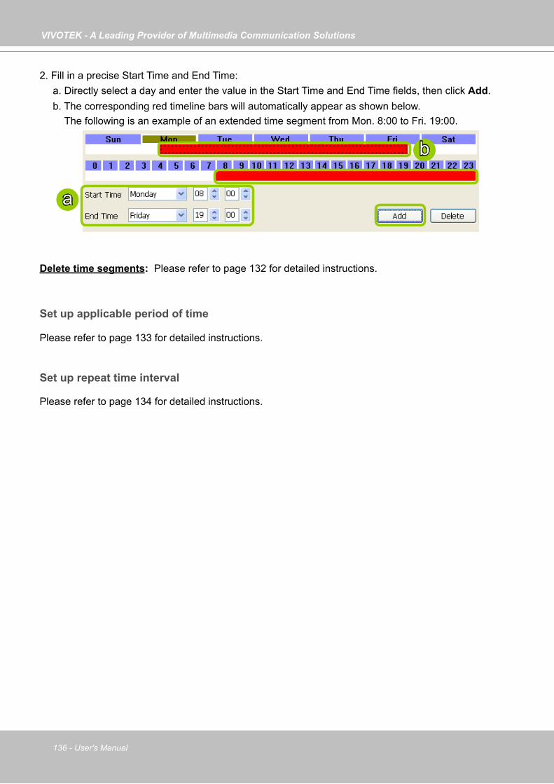
VIVOTEK - A Leading Provider of Multimedia Communication Solutions
136 - User's Manual
2. Fill in a precise Start Time and End Time: a. Directly select a day and enter the value in the Start Time and End Time fields, then click Add.b. The corresponding red timeline bars will automatically appear as shown below. The following is an example of an extended time segment from Mon. 8:00 to Fri. 19:00.
Delete time segments: Please refer to page 132 for detailed instructions.
Set up applicable period of time
Please refer to page 133 for detailed instructions.
Set up repeat time interval
Please refer to page 134 for detailed instructions.
a
b
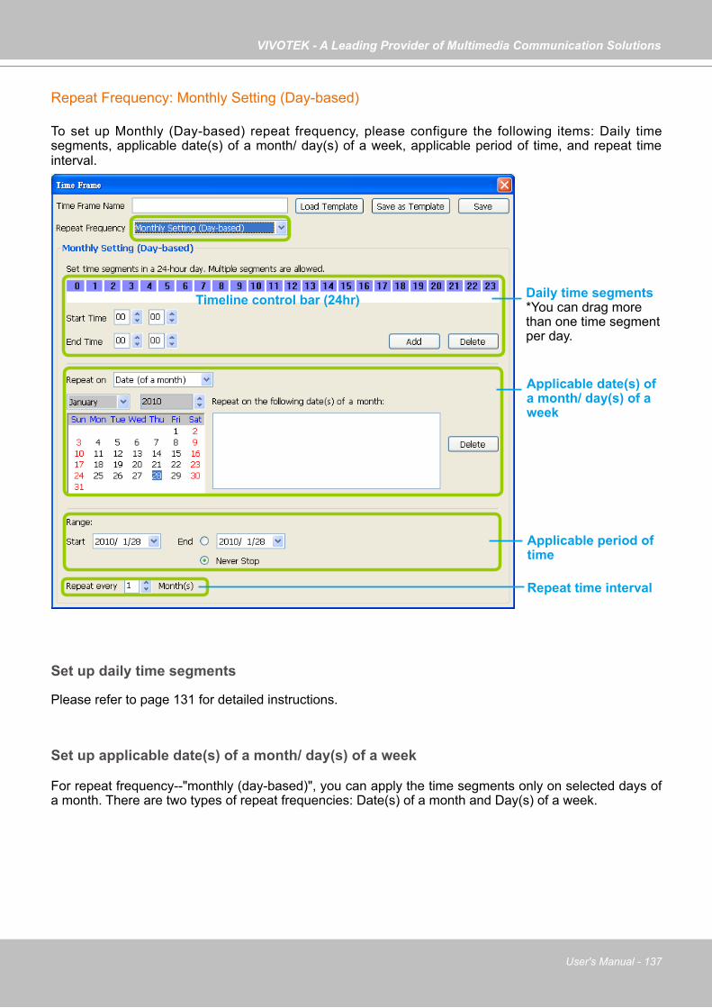
VIVOTEK - A Leading Provider of Multimedia Communication Solutions
User's Manual - 137
Repeat Frequency: Monthly Setting (Day-based)
To set up Monthly (Day-based) repeat frequency, please configure the following items: Daily time segments, applicable date(s) of a month/ day(s) of a week, applicable period of time, and repeat time interval.
Set up daily time segments
Please refer to page 131 for detailed instructions.
Set up applicable date(s) of a month/ day(s) of a week
For repeat frequency--"monthly (day-based)", you can apply the time segments only on selected days of a month. There are two types of repeat frequencies: Date(s) of a month and Day(s) of a week.
Daily time segments *You can drag more than one time segment per day.
Timeline control bar (24hr)
Applicable date(s) of a month/ day(s) of a week
Applicable period of time
Repeat time interval

VIVOTEK - A Leading Provider of Multimedia Communication Solutions
138 - User's Manual
Repeat by date(s) of a month: Select date(s) from the calendar, and it will be displayed on the right blank as shown below.The following example refers to the 1st ~ 5th day of a month.
Repeat by day(s) of a week: Select day(s) from the calendar, and it will be displayed on the right blank as shown below.The following example refers to the 1st ~ 5th Friday of a month.
Set up applicable period of time
Please refer to page 133 for detailed instructions.
Set up repeat time interval
The repeat time intervals is "every N month(s)" as shown below. Repeat every 1 month means the time frame would apply for every month within the period of time.
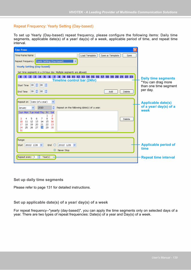
VIVOTEK - A Leading Provider of Multimedia Communication Solutions
User's Manual - 139
Repeat Frequency: Yearly Setting (Day-based)
To set up Yearly (Day-based) repeat frequency, please configure the following items: Daily time segments, applicable date(s) of a year/ day(s) of a week, applicable period of time, and repeat time interval.
Set up daily time segments
Please refer to page 131 for detailed instructions.
Set up applicable date(s) of a year/ day(s) of a week
For repeat frequency--"yearly (day-based)", you can apply the time segments only on selected days of a year. There are two types of repeat frequencies: Date(s) of a year and Day(s) of a week.
Daily time segments *You can drag more than one time segment per day.
Timeline control bar (24hr)
Applicable date(s) of a year/ day(s) of a week
Applicable period of time
Repeat time interval
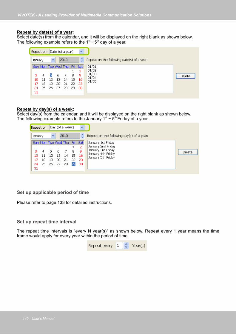
VIVOTEK - A Leading Provider of Multimedia Communication Solutions
140 - User's Manual
Repeat by date(s) of a year: Select date(s) from the calendar, and it will be displayed on the right blank as shown below.The following example refers to the 1st ~ 5th day of a year.
Repeat by day(s) of a week: Select day(s) from the calendar, and it will be displayed on the right blank as shown below.The following example refers to the January 1st ~ 5th Friday of a year.
Set up applicable period of time
Please refer to page 133 for detailed instructions.
Set up repeat time interval
The repeat time intervals is "every N year(s)" as shown below. Repeat every 1 year means the time frame would apply for every year within the period of time.
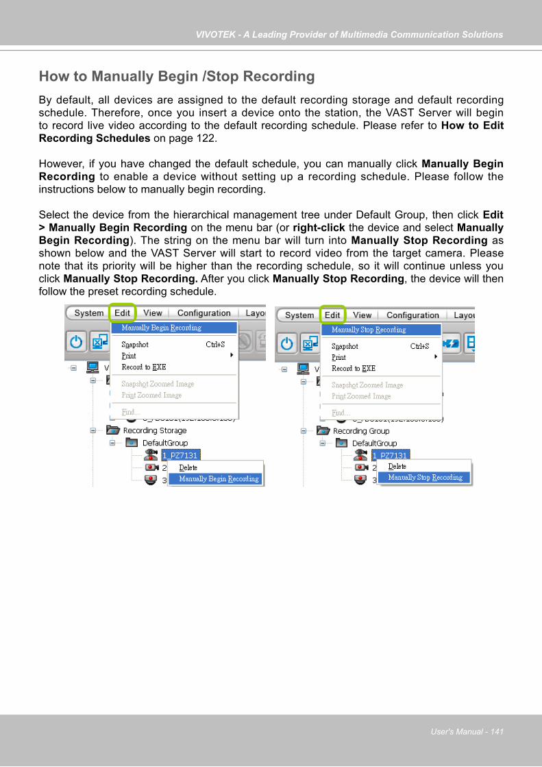
VIVOTEK - A Leading Provider of Multimedia Communication Solutions
User's Manual - 141
How to Manually Begin /Stop RecordingBy default, all devices are assigned to the default recording storage and default recording schedule. Therefore, once you insert a device onto the station, the VAST Server will begin to record live video according to the default recording schedule. Please refer to How to Edit Recording Schedules on page 122.
However, if you have changed the default schedule, you can manually click Manually Begin Recording to enable a device without setting up a recording schedule. Please follow the instructions below to manually begin recording.
Select the device from the hierarchical management tree under Default Group, then click Edit > Manually Begin Recording on the menu bar (or right-click the device and select Manually Begin Recording). The string on the menu bar will turn into Manually Stop Recording as shown below and the VAST Server will start to record video from the target camera. Please note that its priority will be higher than the recording schedule, so it will continue unless you click Manually Stop Recording. After you click Manually Stop Recording, the device will then follow the preset recording schedule.

VIVOTEK - A Leading Provider of Multimedia Communication Solutions
142 - User's Manual
How to Edit Scheduled Backup SettingsVAST LiveClient supports scheduled backup which allows the user to back up the recorded data in another disk.Please follow the steps below to enable scheduled backup settings:a. Select the target station from the hierarchical management tree.b. Click Configuration > Station Settings > Scheduled Backup Settings on the menu bar (or right-
click the station and select Station Settings > Scheduled Backup Settings).
c. The Scheduled backup settings window will pop up.
Select Backup Sourced. Check Enable schedule backup.e. Select the data source you want to backup. If you check Selected cameras, you can click >> or << to
choose the data source that you want to backup.
de
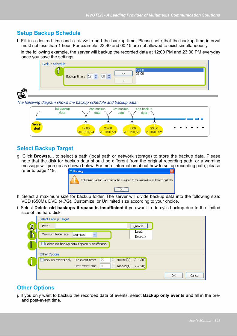
VIVOTEK - A Leading Provider of Multimedia Communication Solutions
User's Manual - 143
Setup Backup Schedulef. Fill in a desired time and click >> to add the backup time. Please note that the backup time interval
must not less than 1 hour. For example, 23:40 and 00:15 are not allowed to exist simultaneously. In the following example, the server will backup the recorded data at 12:00 PM and 23:00 PM everyday
once you save the settings.
The following diagram shows the backup schedule and backup data:
Select Backup Targetg. Click Browse... to select a path (local path or network storage) to store the backup data. Please
note that the disk for backup data should be different from the original recording path, or a warning message will pop up as shown below. For more information about how to set up recording path, please refer to page 119.
h. Select a maximum size for backup folder. The server will divide backup data into the following size: VCD (650M), DVD (4.7G), Customize, or Unlimited size according to your choice.
i. Select Delete old backups if space is insufficient if you want to do cylic backup due to the limited size of the hard disk.
Other Optionsj. If you only want to backup the recorded data of events, select Backup only events and fill in the pre-
and post-event time.
ghi
Server start 12:00
2010/01/2423:00
2010/01/2412:00
2010/01/2523:00
2010/01/25
2nd backup data
1st backup data
3rd backup data
4nd backup data
f
j

VIVOTEK - A Leading Provider of Multimedia Communication Solutions
144 - User's Manual
How to Configure Station Server SettingsVAST LiveClient supports Server Settings including DDNS Settings, Network Storage Settings, and SMTP Settings.Select the station from the hierarchical management tree and click Configuration > Station Settings > Server Settings to open the page (or right-click the station and select Station Settings > Server Settings).
DDNS Settings
Since the public IP of VAST Server may be a dynamic IP address, DDNS service will give it a fixed domain name. Select a DDNS provider from the provider drop-down list. VIVOTEK offers 2bthere.net (Safe100.net), a free dynamic domain name service, to VIVOTEK customers. Please refer to the user's manual of VIVOTEK's network camera for detailed DDNS settings.

VIVOTEK - A Leading Provider of Multimedia Communication Solutions
User's Manual - 145
Network Storage Server Settings
The VAST Server allows user to set up network storage path(s) for recorded files. Please follow the steps below to add a new network storage path.a. Click Add to open the Network Host Window.b. Fill in the related information for the network host. Then click OK to save the new settings.
c. If you want to add more network host(s), please repeat step a. b.
a
b
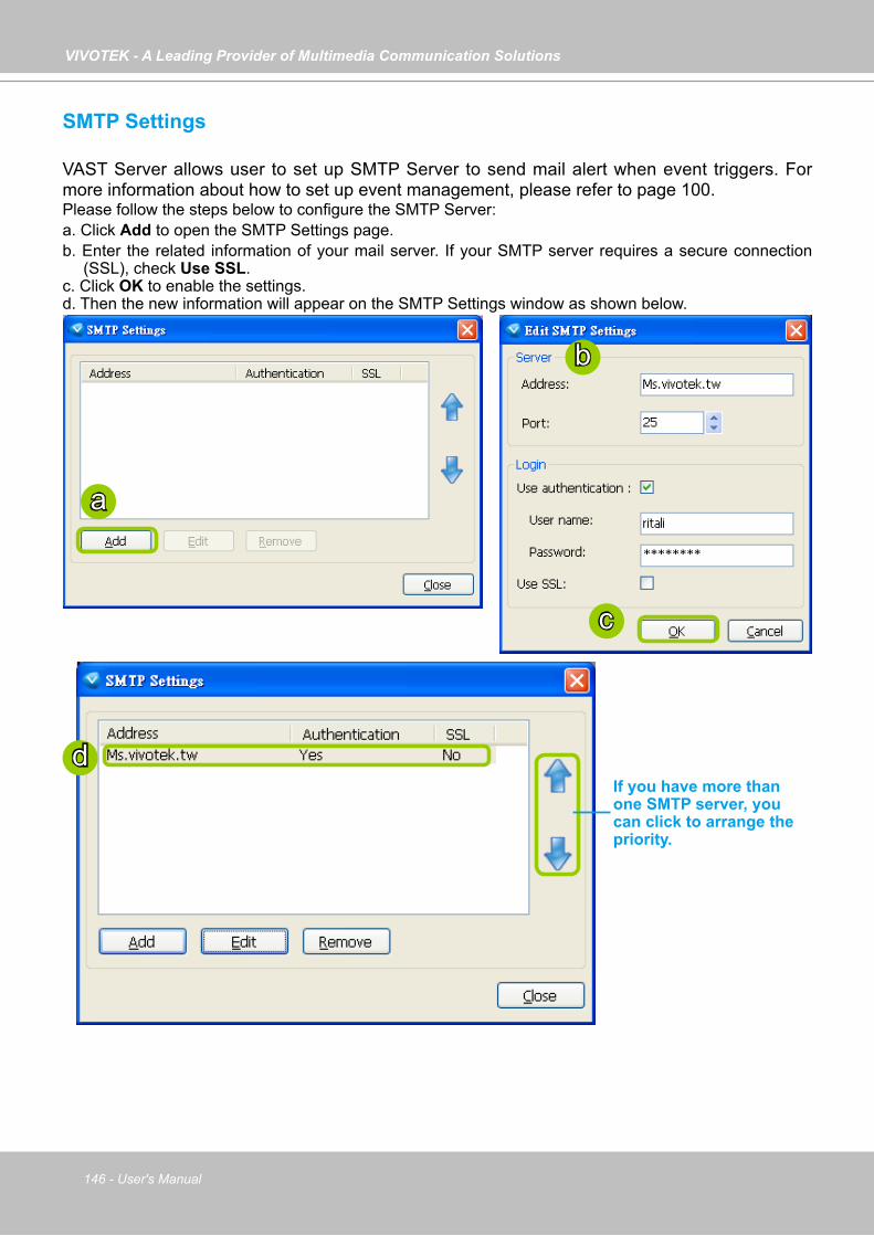
VIVOTEK - A Leading Provider of Multimedia Communication Solutions
146 - User's Manual
SMTP Settings
VAST Server allows user to set up SMTP Server to send mail alert when event triggers. For more information about how to set up event management, please refer to page 100. Please follow the steps below to configure the SMTP Server:a. Click Add to open the SMTP Settings page.b. Enter the related information of your mail server. If your SMTP server requires a secure connection
(SSL), check Use SSL.c. Click OK to enable the settings.d. Then the new information will appear on the SMTP Settings window as shown below.
b
a
c
dIf you have more than one SMTP server, you can click to arrange the priority.
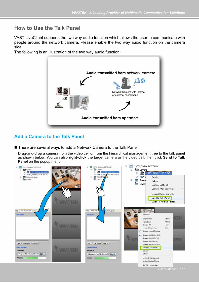
VIVOTEK - A Leading Provider of Multimedia Communication Solutions
User's Manual - 147
How to Use the Talk PanelVAST LiveClient supports the two way audio function which allows the user to communicate with people around the network camera. Please enable the two way audio function on the camera side.The following is an illustration of the two way audio function:
Add a Camera to the Talk Panel
There are several ways to add a Network Camera to the Talk Panel:Drag-and-drop a camera from the video cell or from the hierarchical management tree to the talk panel as shown below. You can also right-click the target camera or the video cell, then click Send to Talk Panel on the popup menu.
Audio transmitted from operators
Audio transmitted from network camera
Network Camera with internal or external microphone

VIVOTEK - A Leading Provider of Multimedia Communication Solutions
148 - User's Manual
An icon with the camera name will be displayed in the Talk Panel.
Please note that you cannot Talk and Play Sound at the same time. When you are talking or playing sound, you cannot add other cameras to the Talk Panel. If you want to add more
cameras to the Talk Panel, please Stop Talking and Stop Playing first.
Click to stop talking Click to stop playing
Remove all cameras from the Talk Panel
Click to play sound from the camera
Click to talk
Click to adjust volume
Click to play the selected sound on the client side
Select sound from the file list
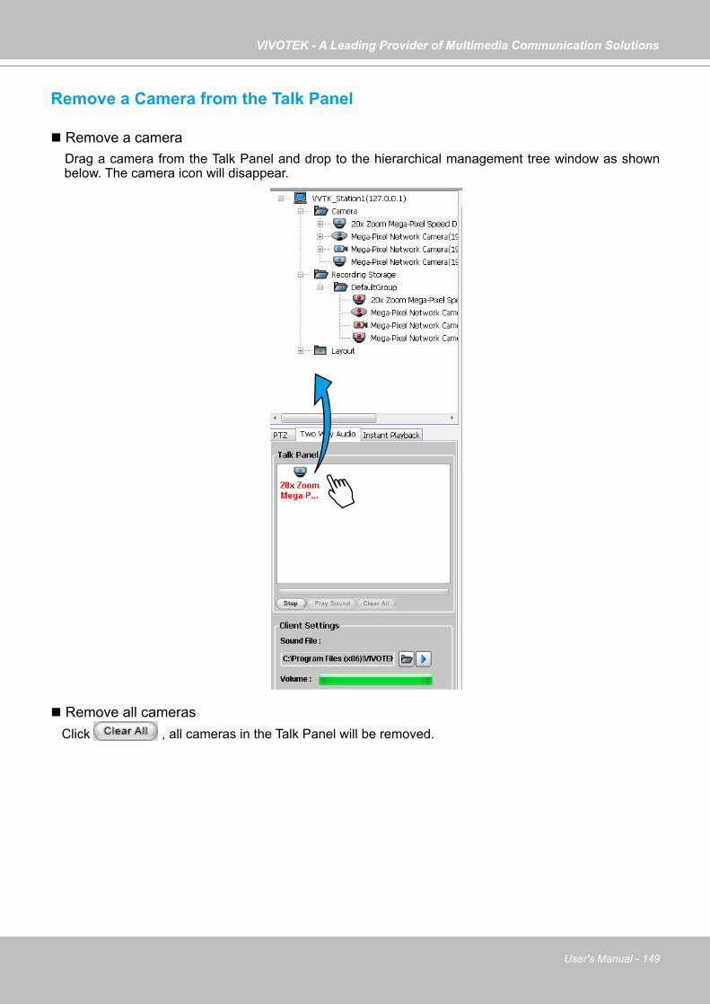
VIVOTEK - A Leading Provider of Multimedia Communication Solutions
User's Manual - 149
Remove a Camera from the Talk Panel
Remove a camera Drag a camera from the Talk Panel and drop to the hierarchical management tree window as shown
below. The camera icon will disappear.
Remove all cameras Click , all cameras in the Talk Panel will be removed.
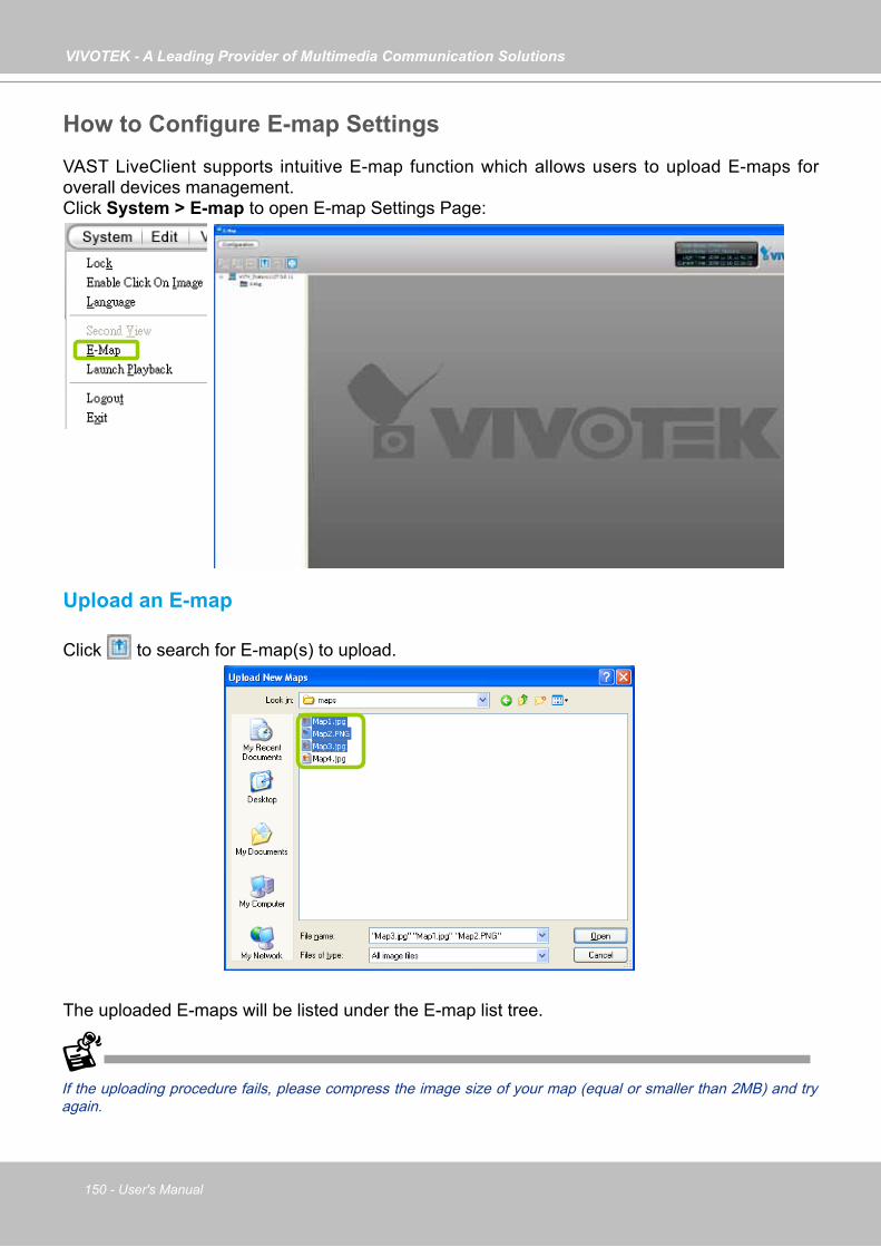
VIVOTEK - A Leading Provider of Multimedia Communication Solutions
150 - User's Manual
How to Configure E-map SettingsVAST LiveClient supports intuitive E-map function which allows users to upload E-maps for overall devices management.Click System > E-map to open E-map Settings Page:
Upload an E-map
Click to search for E-map(s) to upload.
The uploaded E-maps will be listed under the E-map list tree.
If the uploading procedure fails, please compress the image size of your map (equal or smaller than 2MB) and try again.

VIVOTEK - A Leading Provider of Multimedia Communication Solutions
User's Manual - 151
User Interface of E-map Settings Page (View Mode)
Double-click an E-map on the tree, it will be displayed on the E-map window as shown below. There are two operation modes of E-map settings page: "View Mode" and "Edit Mode". The following is the "View Mode" illustration.
A. Menu bar B. Quick access bar C. E-map list tree D. E-map window E. Status panel
Right-click the E-map, then you can Edit, Rename, or Delete the E-map.
B
A
C
ED

VIVOTEK - A Leading Provider of Multimedia Communication Solutions
152 - User's Manual
Right-click an E-map on the tree and click Edit or click on the Quick Access Bar, it will switch to edit mode.
Quick Access Bar
Status Panel
Icon Function Description
Zoom in Zoom in the E-map
Zoom out Zoom out the E-map
Default size Adjust the E-map to default size
Upload Upload E-map to the login station
View Mode Click to switch to view mode
Full Screen Extend the E-map settings page to full screen
Save Save E-map settings
User NameStation Name (IP Address)Login Time (yyyy-mm-dd hh:mm:ss)Current Time (yyyy-mm-dd hh:mm:ss)

VIVOTEK - A Leading Provider of Multimedia Communication Solutions
User's Manual - 153
User Interface of E-map Settings Page (Edit Mode)
A. Menu bar B. Quick access bar C. E-map list tree D. Device tree E. Map preview F. E-map window G. Status panel
Right-click the E-map, you can Edit, Rename, or Delete the E-map.
B
A
C
D
E
GF

VIVOTEK - A Leading Provider of Multimedia Communication Solutions
154 - User's Manual
Device Management
Please follow the steps below to edit an uploaded E-map.a. Double-click the E-map you want to edit, it will be displayed on the E-map window. b. Use Quick Access Bar to adjust the size of the E-map. In edit mode, you can also use your mouse to
drag the position of the E-map and zoom in or zoom out the E-map.c. Drag-and-drop the connected devices to the E-map according to your deployment.
d. Right-click the device icon on E-map, you can rotate the direction or delete the device. The device can be rotated in 8 derections as shown below.
e. You can also drag the DI/DO device under the connected device onto the E-map. If you want to change the status of the DO device, double click the DO icon on E-map.
f. Click on the Quick Access Bar to save the new settings.
b
c
/ Digital input on / off
/ Digital output on / off
The red frame twinkling around the device means there is event trigger(s) going on.Meanwhile, a live view dialog will pop up beside the model.
For more information about DI/DO settings, please refer to Association Management on page 98.

VIVOTEK - A Leading Provider of Multimedia Communication Solutions
User's Manual - 155
Live View Dialog Settings
Click Configuration > E-map Settings to open the E-map Settings dialog, then you can choose to Open Live View Dialog or to Send to Single View when you double-click the device deployed on the E-map.
Open Live View Dialog
Select Open Live View Dialog: When you double-click the device icon on the E-map or when an event triggers, a live view dialog will pop up beside it. It is the default setting in E-map Settings window.
Send to Single View
Select Send to Single View: When you double-click the device icon on the E-map, it will open a single view on the VAST LiveClient.
If you have set up dual monitor, it will be automatically sent a single view to the second monitor.Monitor 1 Monitor 2
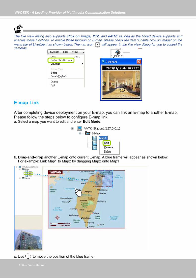
VIVOTEK - A Leading Provider of Multimedia Communication Solutions
156 - User's Manual
E-map Link
After completing device deployment on your E-map, you can link an E-map to another E-map.Please follow the steps below to configure E-map link:a. Select a map you want to edit and enter Edit Mode.
b. Drag-and-drop another E-map onto current E-map. A blue frame will appear as shown below. For example: Link Map1 to Map2 by dargging Map2 onto Map1
c. Use to move the position of the blue frame.
The live view dialog also supports click on image, PTZ, and e-PTZ as long as the linked device supports and enables those functions. To enable those function on E-map, please check the item "Enable click on image" on the menu bar of LiveClient as shown below. Then an icon will appear in the live view dialog for you to control the cameras.
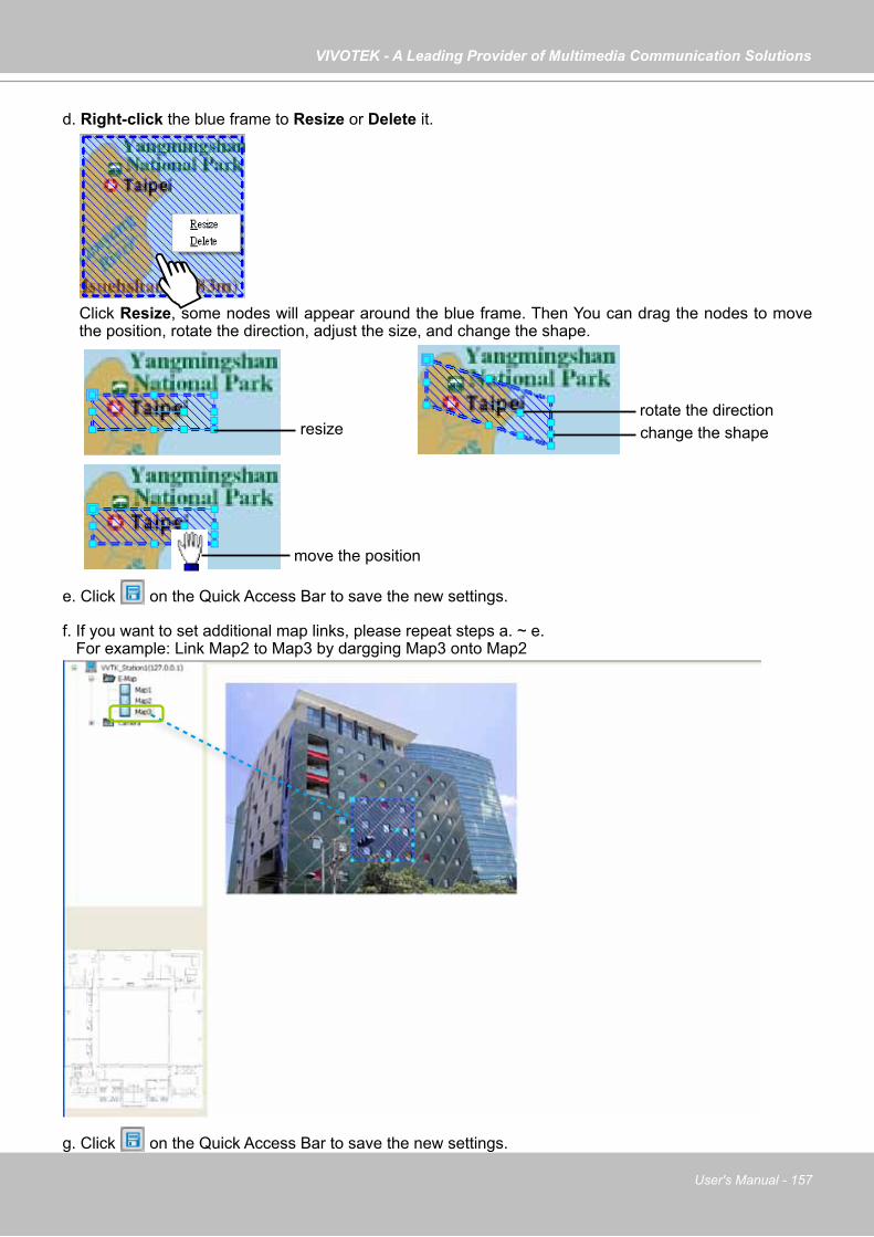
VIVOTEK - A Leading Provider of Multimedia Communication Solutions
User's Manual - 157
d. Right-click the blue frame to Resize or Delete it.
Click Resize, some nodes will appear around the blue frame. Then You can drag the nodes to move the position, rotate the direction, adjust the size, and change the shape.
e. Click on the Quick Access Bar to save the new settings.
f. If you want to set additional map links, please repeat steps a. ~ e. For example: Link Map2 to Map3 by dargging Map3 onto Map2
g. Click on the Quick Access Bar to save the new settings.
resize change the shaperotate the direction
move the position
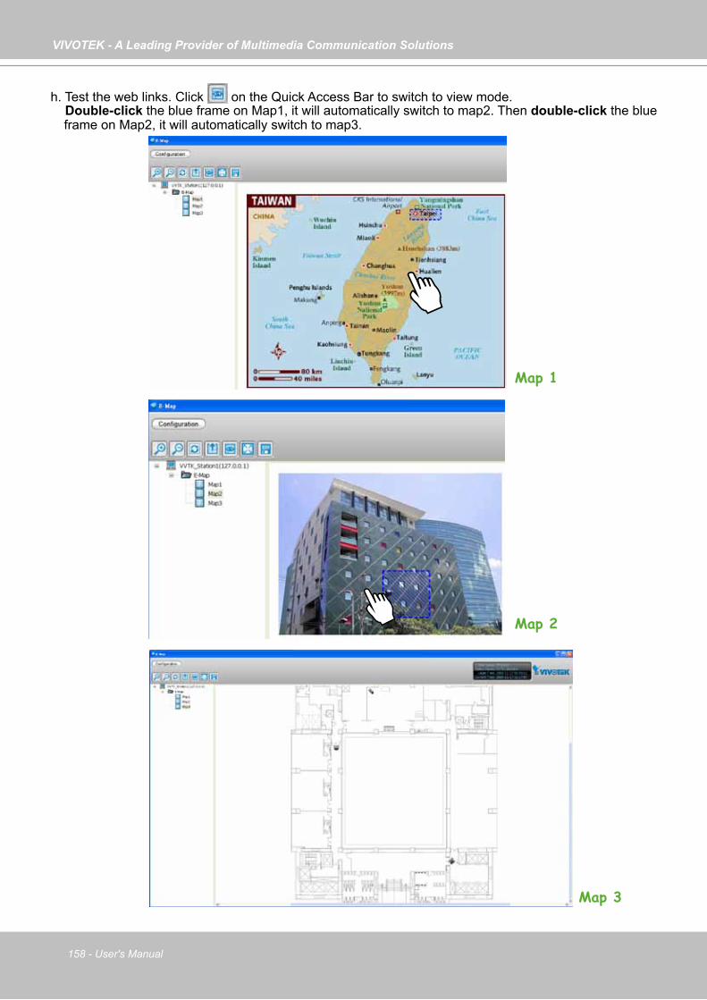
VIVOTEK - A Leading Provider of Multimedia Communication Solutions
158 - User's Manual
h. Test the web links. Click on the Quick Access Bar to switch to view mode. Double-click the blue frame on Map1, it will automatically switch to map2. Then double-click the blue
frame on Map2, it will automatically switch to map3.
Map 1
Map 2
Map 3

VIVOTEK - A Leading Provider of Multimedia Communication Solutions
User's Manual - 159
How to Configure Client SettingsIn Client Settings, you can configure Snapshot Settings, Recording Settings, View Settings, General Settings, Joystick Settings, Proxy Settings, and PiP Settings.
Snapshot SettingsPlease follow the steps below to configure snapshot settings:a. Click Configuration > Client Settings > Snapshot Settings on the menu bar to open the Snapshot
Settings window. b. Select a picture format for snapshots (BMP or JPEG). If you select JPEG format, you can adjust the
recompression quality (from 1 to 100). Note that a higher value would generate higher picture quality but lower compression rate.
c. Fill in a filename prefix for the snapshots.d. The default storage path for snapshots is C:\Users\Public\Documents\VIVOTEKInc\VAST\Client\
LiveClient. If you want to change the storage path, click Browse to select another folder.
e. If you check Generate a file name automatically, VAST will directly save snapshots with the following filename format to the storage folder.
Snapshot_20100125_173015_01.jpg
File name prefix Date and time (YYYYMMDD_hhmmss)
Serial number of snapshots
Picture format
bc
d
eThe recompression quality is only enabled in MPEG-4 streaming. If your stream source is MJPEG, the system will directly save the JPEG image without recompression.

VIVOTEK - A Leading Provider of Multimedia Communication Solutions
160 - User's Manual
If you uncheck Generate a file name automatically, the Save file dialog box will pop up when you take a snapshot. The file name prefix will automatically be displayed in the Save File dialog box.
Take a Snapshot
Please follow the steps below to take a snapshot of the live video stream:a. Select the video cell of which you want to take a snapshot.b. Click Snapshot on the quick access bar, or right-click the video cell and select Others >
Snapshot from the popup menu. You also can click Edit > Snapshot to take a snapshot.
c. The snapshots will be found in the preset storage folder on your local computer.
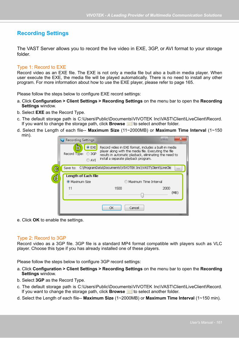
VIVOTEK - A Leading Provider of Multimedia Communication Solutions
User's Manual - 161
Recording Settings
The VAST Server allows you to record the live video in EXE, 3GP, or AVI format to your storage folder.
Type 1: Record to EXE Record video as an EXE file. The EXE is not only a media file but also a built-in media player. When user execute the EXE, the media file will be played automatically. There is no need to install any other program. For more information about how to use the EXE player, please refer to page 165.
Please follow the steps below to configure EXE record settings:a. Click Configuration > Client Settings > Recording Settings on the menu bar to open the Recording
Settings window.b. Select EXE as the Record Type.c. The default storage path is C:\Users\Public\Documents\VIVOTEK Inc\VAST\Client\LiveClient\Record.
If you want to change the storage path, click Browse to select another folder.d. Select the Length of each file-- Maximum Size (11~2000MB) or Maximum Time Interval (1~150
min).
e. Click OK to enable the settings.
Type 2: Record to 3GPRecord video as a 3GP file. 3GP file is a standard MP4 format compatible with players such as VLC player. Choose this type if you has already installed one of these players.
Please follow the steps below to configure 3GP record settings:a. Click Configuration > Client Settings > Recording Settings on the menu bar to open the Recording
Settings window.b. Select 3GP as the Record Type.c. The default storage path is C:\Users\Public\Documents\VIVOTEK Inc\VAST\Client\LiveClient\Record.
If you want to change the storage path, click Browse to select another folder.d. Select the Length of each file-- Maximum Size (1~2000MB) or Maximum Time Interval (1~150 min).
b
cd
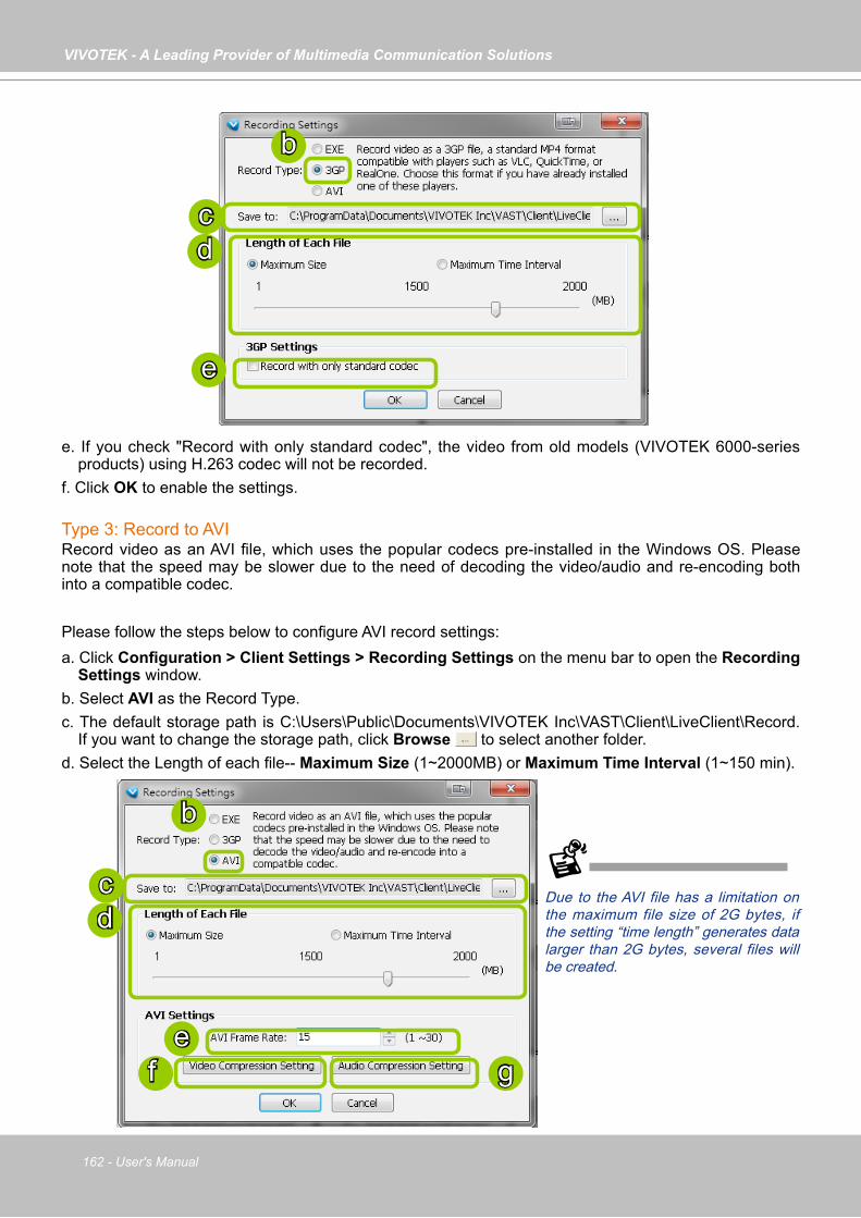
VIVOTEK - A Leading Provider of Multimedia Communication Solutions
162 - User's Manual
e. If you check "Record with only standard codec", the video from old models (VIVOTEK 6000-series products) using H.263 codec will not be recorded.
f. Click OK to enable the settings.
Type 3: Record to AVIRecord video as an AVI file, which uses the popular codecs pre-installed in the Windows OS. Please note that the speed may be slower due to the need of decoding the video/audio and re-encoding both into a compatible codec.
Please follow the steps below to configure AVI record settings:a. Click Configuration > Client Settings > Recording Settings on the menu bar to open the Recording
Settings window.b. Select AVI as the Record Type.c. The default storage path is C:\Users\Public\Documents\VIVOTEK Inc\VAST\Client\LiveClient\Record.
If you want to change the storage path, click Browse to select another folder.d. Select the Length of each file-- Maximum Size (1~2000MB) or Maximum Time Interval (1~150 min).
b
cd
e
b
cd
ef g
Due to the AVI file has a limitation on the maximum file size of 2G bytes, if the setting “time length” generates data larger than 2G bytes, several files will be created.
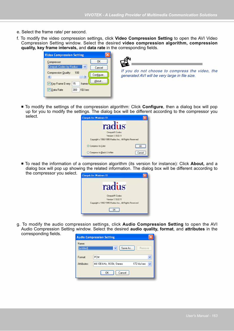
VIVOTEK - A Leading Provider of Multimedia Communication Solutions
User's Manual - 163
e. Select the frame rate/ per second. f. To modify the video compression settings, click Video Compression Setting to open the AVI Video
Compression Setting window. Select the desired video compression algorithm, compression quality, key frame intervals, and data rate in the corresponding fields.
To modify the settings of the compression algorithm: Click Configure, then a dialog box will pop up for you to modify the settings. The dialog box will be different according to the compressor you select.
To read the information of a compression algorithm (its version for instance): Click About, and a dialog box will pop up showing the related information. The dialog box will be different according to the compressor you select.
g. To modify the audio compression settings, click Audio Compression Setting to open the AVI Audio Compression Setting window. Select the desired audio quality, format, and attributes in the corresponding fields.
If you do not choose to compress the video, the generated AVI will be very large in file size.
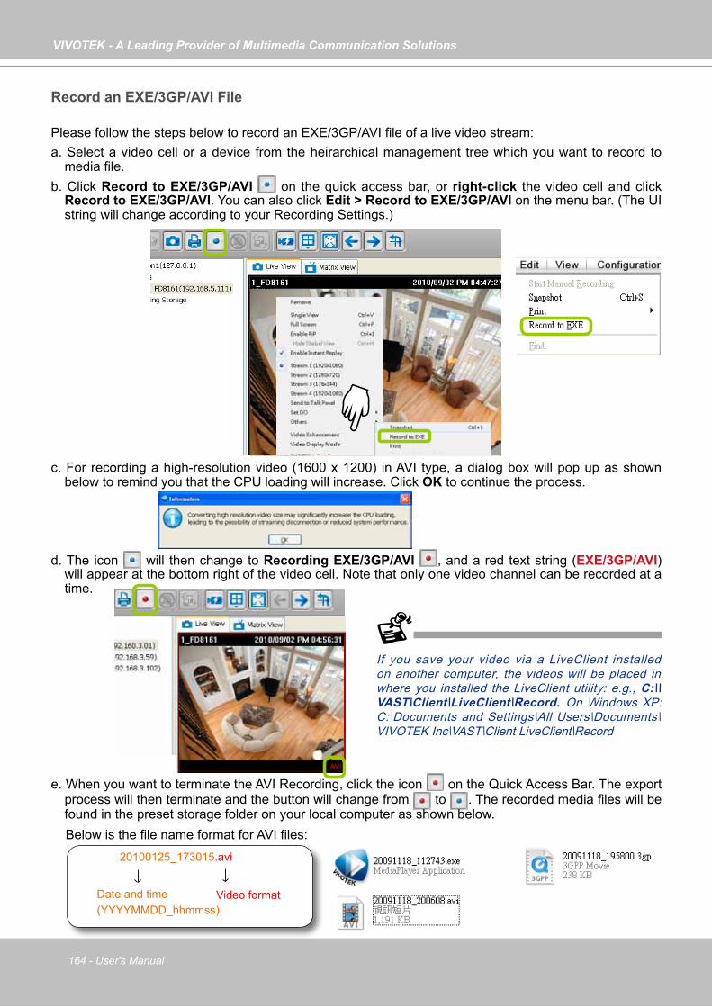
VIVOTEK - A Leading Provider of Multimedia Communication Solutions
164 - User's Manual
Record an EXE/3GP/AVI File
Please follow the steps below to record an EXE/3GP/AVI file of a live video stream:a. Select a video cell or a device from the heirarchical management tree which you want to record to
media file.b. Click Record to EXE/3GP/AVI on the quick access bar, or right-click the video cell and click
Record to EXE/3GP/AVI. You can also click Edit > Record to EXE/3GP/AVI on the menu bar. (The UI string will change according to your Recording Settings.)
c. For recording a high-resolution video (1600 x 1200) in AVI type, a dialog box will pop up as shown below to remind you that the CPU loading will increase. Click OK to continue the process.
d. The icon will then change to Recording EXE/3GP/AVI , and a red text string (EXE/3GP/AVI) will appear at the bottom right of the video cell. Note that only one video channel can be recorded at a time.
e. When you want to terminate the AVI Recording, click the icon on the Quick Access Bar. The export process will then terminate and the button will change from to . The recorded media files will be found in the preset storage folder on your local computer as shown below.
Below is the file name format for AVI files:
AVI
20100125_173015.avi
Date and time (YYYYMMDD_hhmmss)
Video format
If you save your video via a LiveClient installed on another computer, the videos will be placed in where you installed the LiveClient utility: e.g., C:\\VAST\Client\LiveClient\Record. On Windows XP: C:\Documents and Settings\All Users\Documents\VIVOTEK Inc\VAST\Client\LiveClient\Record

VIVOTEK - A Leading Provider of Multimedia Communication Solutions
User's Manual - 165
Built-in Media Player--EXE
Below is the icon of footages saved as EXE files. Double-click on it, the recorded video will be played automatically as shown below. You may also open the built-in Media Player in the default location: C:\Program Files\VIVOTEK Inc\VAST\Client\LiveClient. On Windows XP: C:\Documents and Settings\All Users\Documents\VIVOTEK Inc\VAST\Client\LiveClient\Record.
Icon Function Description
Pause Pause playback of the focused video clip
Play Start playback of the focused video clip
Next Frame Go to the next video frame of the focused video clip
Slow Down Slow down the playback rate
Speed Up Speed up the playback rate
IP8172
Control Buttons
Timeline Slider
Status Panel
Current time of the video clip
Total length of the histogram
The playing rate can be 1/8, 1/4, 1/2, 1X, 2X, 4X.
Video Title

VIVOTEK - A Leading Provider of Multimedia Communication Solutions
166 - User's Manual
The function menu of the built-in media player are displayed as shown below:
The built-in player is able to playback 3GP and EXE files. The built-in player is able to save 3GP files as EXE files. The built-in player is able to save EXE files as 3GP files. The built-in player is able to convert EXE and 3GP files into AVI files. The built-in player also supports snapshot and print functions.
Below are special notices related to video recording with the fisheye cameras: For recorded videos from the fisheye cameras, only the built-in Media Player can playback the
Regional or Panoramic views. If you access the recorded videos using other playback software, you will end up seeing the circular-shape Original view.
When recording videos from fisheye cameras, Regional and Panoramic views can only be preserved in the EXE and 3GP format. If you save the dewarped views, i.e., Regional and Panoramic, as AVIs, only the circular Original view will be preserved.
Currently the video playback on the Emap window displays the Original view only. To display a Regional or Panoramic view, right-click on the Media Player window.
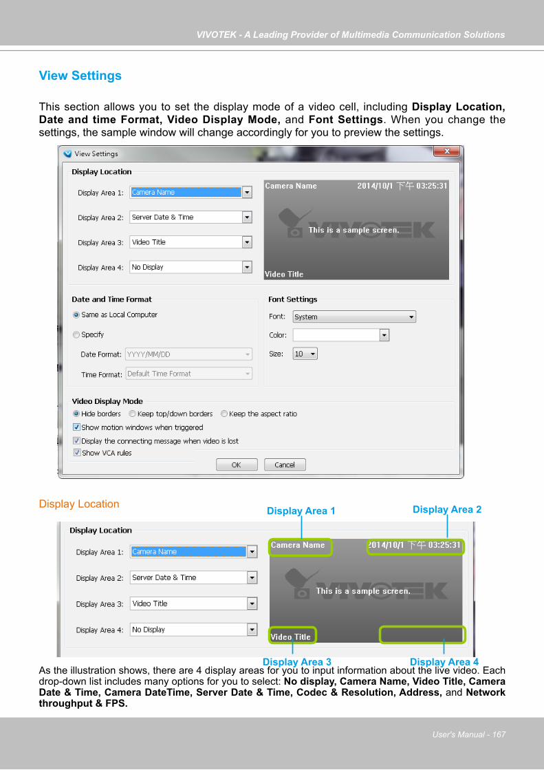
VIVOTEK - A Leading Provider of Multimedia Communication Solutions
User's Manual - 167
View Settings
This section allows you to set the display mode of a video cell, including Display Location, Date and time Format, Video Display Mode, and Font Settings. When you change the settings, the sample window will change accordingly for you to preview the settings.
Display Location
As the illustration shows, there are 4 display areas for you to input information about the live video. Each drop-down list includes many options for you to select: No display, Camera Name, Video Title, Camera Date & Time, Camera DateTime, Server Date & Time, Codec & Resolution, Address, and Network throughput & FPS.
Display Area 1 Display Area 2
Display Area 3 Display Area 4

VIVOTEK - A Leading Provider of Multimedia Communication Solutions
168 - User's Manual
Date and Time Format
Same as local computer: Select this option and then the date and time format will synchronize with the local computer.
Specify: Select a desired format for the date and time from the drop-down list. Date format: Select YYYY/MM/DD or MM/DD/YY. Time format: Select the default time format (synchronize with the local computer), 12h AM/PM, or 24h.
Video Display Mode
Show motion window when triggered: If you select this option, the red frame of the motion detection window will appear in the video window when motion is triggered. This function is enabled as default.
Display the connecting message when video is lost:indow will appear in the video window when motion is triggered. This function is enabled as default.
Show VCA rules: VCA rules refer to the Line Crossing and Field Detection lines drawn on individual video screens. These VCA functions are configured on the web consoles with cameras, not on the VAST LiveClient.
For detailed information about how to set up the layout of the live view window, please refer to How to Change Video Viewing Mode on page 75.
Keep the aspect ratio: In the default settings, the size of the video window will change according to the layout of the live view window you choose. However, the frame size may be distorted.
Keep the aspect ratio: If you select Keep the aspect ratio, the video window will be adjusted to the same frame size as the preview window. This function is disabled as default.
The Display options can also be accessed by a right-click on the view cell.
Keep top/down borders: the camera name, video title, and time will be displayed on the black borders instead of displaying floating text on the screen.

VIVOTEK - A Leading Provider of Multimedia Communication Solutions
User's Manual - 169
Font Settings
This function allows you to change the font on the video cell.
Font: Automatically lists all fonts installed on your operating system. Select the desired type. Color: Select a desired font color (white, red, green, blue). Size: Select a desired font size (8, 10, 12, 14).
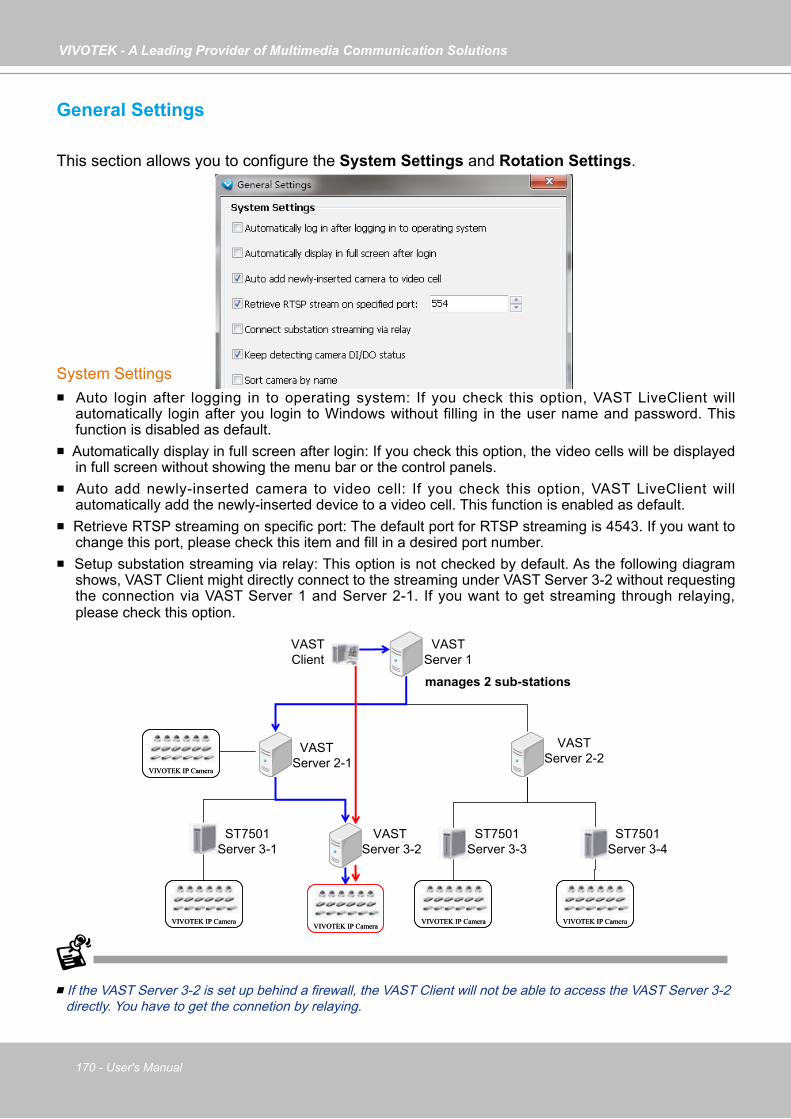
VIVOTEK - A Leading Provider of Multimedia Communication Solutions
170 - User's Manual
General Settings
This section allows you to configure the System Settings and Rotation Settings.
System Settings Auto login after logging in to operating system: If you check this option, VAST LiveClient will
automatically login after you login to Windows without filling in the user name and password. This function is disabled as default.
Automatically display in full screen after login: If you check this option, the video cells will be displayed in full screen without showing the menu bar or the control panels.
Auto add newly-inserted camera to video cell: If you check this option, VAST LiveClient will automatically add the newly-inserted device to a video cell. This function is enabled as default.
Retrieve RTSP streaming on specific port: The default port for RTSP streaming is 4543. If you want to change this port, please check this item and fill in a desired port number.
Setup substation streaming via relay: This option is not checked by default. As the following diagram shows, VAST Client might directly connect to the streaming under VAST Server 3-2 without requesting the connection via VAST Server 1 and Server 2-1. If you want to get streaming through relaying, please check this option.
If the VAST Server 3-2 is set up behind a firewall, the VAST Client will not be able to access the VAST Server 3-2 directly. You have to get the connetion by relaying.
VIVOTEK IP CameraVIVOTEK IP Camera
ST7501Server 3-1
VASTServer 1
VASTClient
VASTServer 2-1
VIVOTEK IP CameraVIVOTEK IP Camera
VASTServer 3-2
VIVOTEK IP CameraVIVOTEK IP Camera
VIVOTEK IP CameraVIVOTEK IP Camera
ST7501Server 3-3
VASTServer 2-2
VIVOTEK IP CameraVIVOTEK IP Camera
ST7501Server 3-4
manages 2 sub-stations
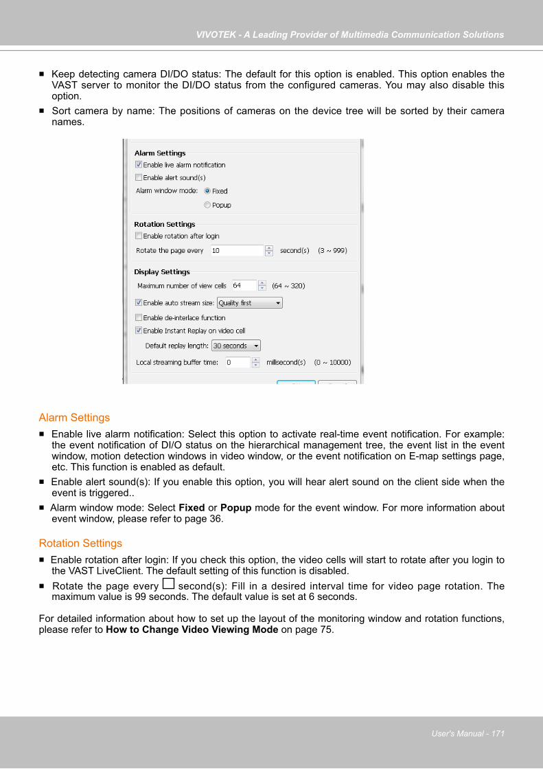
VIVOTEK - A Leading Provider of Multimedia Communication Solutions
User's Manual - 171
Alarm Settings Enable live alarm notification: Select this option to activate real-time event notification. For example:
the event notification of DI/O status on the hierarchical management tree, the event list in the event window, motion detection windows in video window, or the event notification on E-map settings page, etc. This function is enabled as default.
Enable alert sound(s): If you enable this option, you will hear alert sound on the client side when the event is triggered..
Alarm window mode: Select Fixed or Popup mode for the event window. For more information about event window, please refer to page 36.
Rotation Settings Enable rotation after login: If you check this option, the video cells will start to rotate after you login to
the VAST LiveClient. The default setting of this function is disabled. Rotate the page every second(s): Fill in a desired interval time for video page rotation. The
maximum value is 99 seconds. The default value is set at 6 seconds.
For detailed information about how to set up the layout of the monitoring window and rotation functions, please refer to How to Change Video Viewing Mode on page 75.
Keep detecting camera DI/DO status: The default for this option is enabled. This option enables the VAST server to monitor the DI/DO status from the configured cameras. You may also disable this option.
Sort camera by name: The positions of cameras on the device tree will be sorted by their camera names.

VIVOTEK - A Leading Provider of Multimedia Communication Solutions
172 - User's Manual
Display Settings
Maximum number of view cells: This determines the number of view cell on window, and also takes effect with the number of layout pages. For example, if there are 320 channels using the 1+31 layout, there will be 10 layout pages in the LiveClient window. The configuration changes take effect after the LiveClient is re-started.
Enable auto stream size: The Auto Stream Size feature dynamically adjusts the stream sizes of video feeds from network cameras in order to reduce CPU load and bandwidth consumption.
It is often the case that in surveillance deployments the physical dimensions of monitors, the
effectiveness of visual stimulus, and the operators' regions of interest can all be very limited. Streaming large-size videos at all times will be a waste of bandwidth and system computing power. CIF and VGA size videos are usually sufficient for the operators watching surveillance screens.
When enabled, your LiveClient station automatically requests smaller-size streams as video feeds (any from streams #1 ~ #4) from the network cameras. For example, the frame size of video stream #4 will be reduced to 320x240 (CIF). Depending on the actual size of view cells on the LiveClient monitoring screen, the VAST server automatically requests different video streams.
When the size of view cells is manually expanded, a VAST server requests a different stream. This is called Stream Jump. Shown below are the details of the corresponding stream jumps.
View cell size Stream jump to...
4:3 resolutions<= 320x240 stream #4 (CIF)> 320x240 or 640x480 stream #116:9 resolutions
<= 384x216 stream #4 (CIF)> 384x216 or 640x360 stream #11:1 (fisheye cameras)
<= 384x384 stream #4 (CIF)> 384x384 or 640x640 stream #1
Facts about Auto Stream Size:• The Auto Stream Size takes effect when, 1. The size of view cell is changed. 2. Inserting a new camera, or when the "Auto add newly-inserted camera" feature is applied. 3. Double-click or click-and-drag cameras into view cells. 4. When Auto Stream Size feature is enabled (the configuration on this window). 5. Through the layout change. • The LiveClient utility automatically adjusts stream selection according to the size of view cells, no
user's configuration is required.
VIVOTEK - A Leading Provider of Multimedia Communication Solutions
User's Manual - 173
Enable de-interlace function: Select this option if your connected device does not support de-interlace function. For example: VS7100.
Enable Instant Replay on video cell: Here you can change the duration of a playback that happened immediately before a user utilizes the instant playback function.
Local streaming buffer time: Video frames can be temporarily stored on the cache memory of the VAST server for a short, configurable period of time before they are displayed on the Liveview. If the networking condition is less than ideal, this can help delivering a smooth video stream. Note that this feature is not available on a Matrix view and the web console.
Limitations:• For older, single-stream cameras, the Auto Stream Size feature does not take effect. • When the Auto Stream Size feature is enabled, the NR and ND series NVR configured under the
VAST server will be considered as substations. The stream configuration of cameras managed by these NVR substations will not be changed. Only the video codec, bit rate, and frame rate of the video feeds directed through these NVR substations will be changed into a more economic setting.
• For the NR8401 NVR, the Auto Stream Size function may not fully apply. For cameras managed by the NR8401, the following will apply:
Large view cell: default viewing stream. Medium view cell: stream #2. Small view cell: the last stream. • a user disables the Auto Stream Size function later, the frame size of stream #4 will not be
restored to the previous configuration.
• The frame size of stream #1 is user-configurable. The VAST server only resizes stream #4. • If a user disables the Auto Stream Size function later, the frame size of stream #4 will not be
restored to the previous configuration. Stream jump takes place on the display of all connected cameras once the function is enabled.
• The Auto Stream Size function does not apply to the Matrix view. • If users configured a region of interest before the Auto Stream Size function is applied, e.g., via
the ePTZ control, the view cell might display a different live view. • Below is the general rule for stream selection:
stream # configured into VGA stream # configured into CIF
4 streams cameras Stream 2 Stream 43 streams cameras Stream 2 Stream 32 streams cameras none Stream 2
• When a smaller stream is selected, the video quality is set to fixed quality as Good.• The Maximum frame rate is not configured. • The VAST server automatically selects a video resolution of a specific aspect ratio that best fits
the current view cell, and places the video into the view cell.
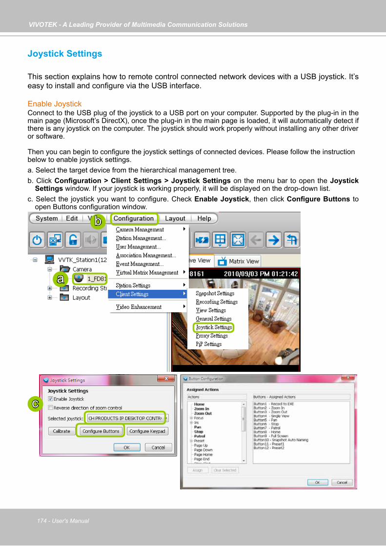
VIVOTEK - A Leading Provider of Multimedia Communication Solutions
174 - User's Manual
Joystick Settings
This section explains how to remote control connected network devices with a USB joystick. It’s easy to install and configure via the USB interface.
Enable JoystickConnect to the USB plug of the joystick to a USB port on your computer. Supported by the plug-in in the main page (Microsoft’s DirectX), once the plug-in in the main page is loaded, it will automatically detect if there is any joystick on the computer. The joystick should work properly without installing any other driveror software.
Then you can begin to configure the joystick settings of connected devices. Please follow the instructionbelow to enable joystick settings.a. Select the target device from the hierarchical management tree.b. Click Configuration > Client Settings > Joystick Settings on the menu bar to open the Joystick
Settings window. If your joystick is working properly, it will be displayed on the drop-down list. c. Select the joystick you want to configure. Check Enable Joystick, then click Configure Buttons to
open Buttons configuration window.
a
b
c

VIVOTEK - A Leading Provider of Multimedia Communication Solutions
User's Manual - 175
Buttons ConfigurationIn Button Configuration window, the left column shows the actions you can assign, and the right column shows the functional buttons and assigned actions. The number of buttons may differ from different joysticks. Please follow the steps below to configure your joystick buttons:a. Choosing one of the actions and click Assign will pop up a dialog. Then you can assign this action to
a button by pressing the joystick button or select it from the drop-down list. For example: Assign Home (move to home position) to Button 1.
Reverse direction of zoom controlDue to different designs in joystick zoom wheel, you can select this checkbox to reverse the zoom in/out directions.
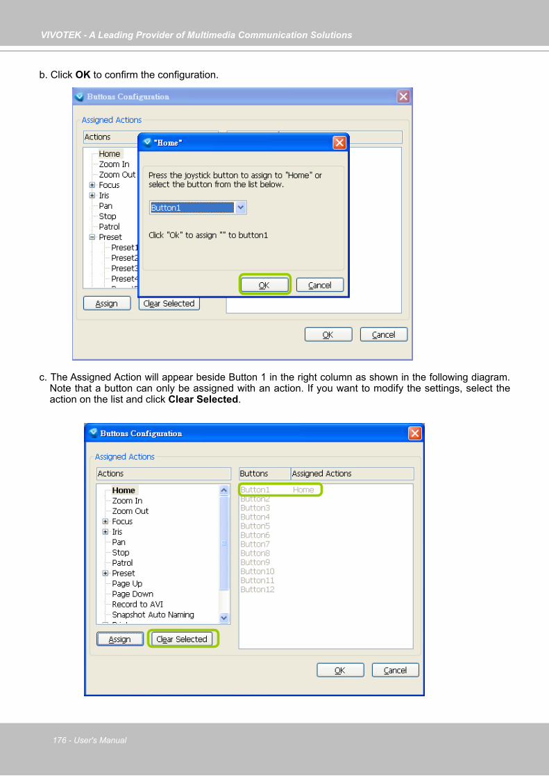
VIVOTEK - A Leading Provider of Multimedia Communication Solutions
176 - User's Manual
b. Click OK to confirm the configuration.
c. The Assigned Action will appear beside Button 1 in the right column as shown in the following diagram. Note that a button can only be assigned with an action. If you want to modify the settings, select the action on the list and click Clear Selected.
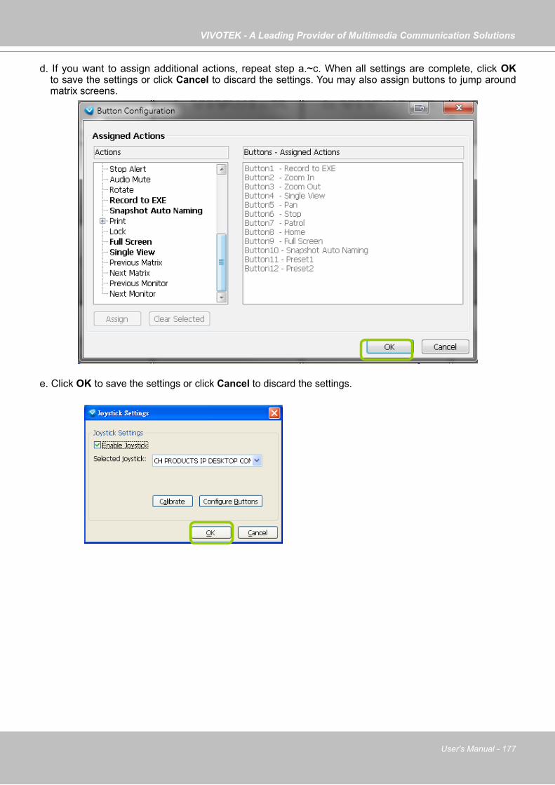
VIVOTEK - A Leading Provider of Multimedia Communication Solutions
User's Manual - 177
d. If you want to assign additional actions, repeat step a.~c. When all settings are complete, click OK to save the settings or click Cancel to discard the settings. You may also assign buttons to jump around matrix screens.
e. Click OK to save the settings or click Cancel to discard the settings.
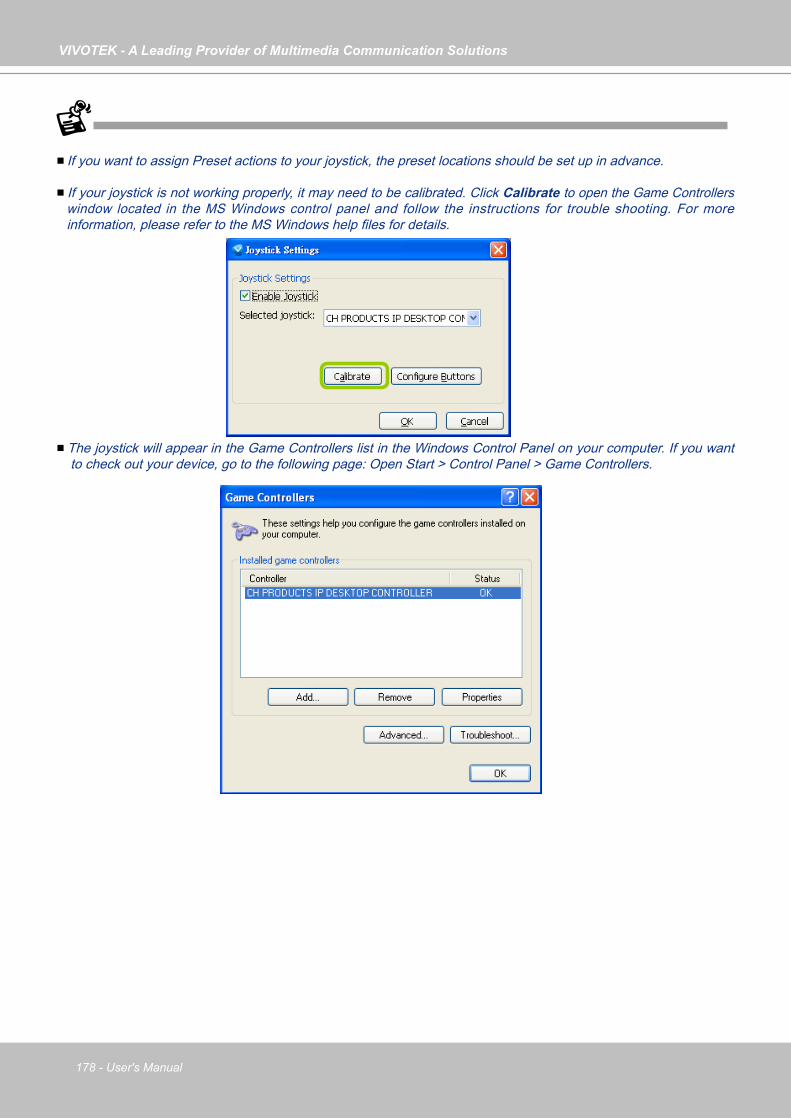
VIVOTEK - A Leading Provider of Multimedia Communication Solutions
178 - User's Manual
If you want to assign Preset actions to your joystick, the preset locations should be set up in advance.
If your joystick is not working properly, it may need to be calibrated. Click Calibrate to open the Game Controllers window located in the MS Windows control panel and follow the instructions for trouble shooting. For more information, please refer to the MS Windows help files for details.
The joystick will appear in the Game Controllers list in the Windows Control Panel on your computer. If you want to check out your device, go to the following page: Open Start > Control Panel > Game Controllers.

VIVOTEK - A Leading Provider of Multimedia Communication Solutions
User's Manual - 179
Configure keypadFor joysticks that come with a keypad, you can use the combination of a number assigned to a camera and the Enter key on keypad to quickly move to the camera’s current view. The current view will be displayed in a single view. To configure the number representative of each camera, double-click to open a configuration window. The number used for quick switch must be mapped to an existing channel.
Also note the following:1. The keypad key representative can be a 4-digit numeric combination. 2. If a number key is pressed without pressing the Enter key within 3 seconds, the command is cancelled.3. You should have at least ONE EMPTY view cell. 4. A Rotation operation will be halted when using the keypad quick switch function. 5. This quick switch function does not take effect on the cameras managed by VAST substations.

VIVOTEK - A Leading Provider of Multimedia Communication Solutions
180 - User's Manual
PTZ/ E-PTZ FunctionIn addition to using the PTZ control panel, you may also control the rotation handle of the joystick to remote control a PTZ/ E-PTZ network camera with ease.
Pan/Tilt: Move the rotation handle of the joystick; you can pan the camera to the desire position. There will be blue line displaying the moving direction in the center of the video image as the diagram 1 below.
Zoom in/Zoom out: Shift the rotation handle clockwise to zoom in the camera on an image or go counterclockwise to zoom out the camera on an image. There will be a circle and four vectors in the center of the video image as the diagram 2, 3 below.
Proxy SettingsIn this section, you can enable, modify, or cancel Proxy Settings for client if your VAST Server is under a proxy. If you change the proxy settings, please fill in the new value next time you login the LiveClient next time.
Zoom in(Turn the rotating handle clockwise)
Zoom out(Turn the rotating handle counter-clockwise)
Pan/Tilt(Move the rotating handle back and forth)
FD8161 FD8161 FD81612010/09/03 PM 03:56:17 2010/09/03 PM 03:56:17 2010/09/03 PM 03:56:17
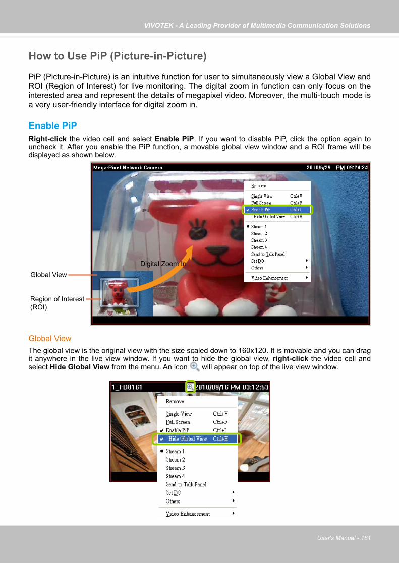
VIVOTEK - A Leading Provider of Multimedia Communication Solutions
User's Manual - 181
How to Use PiP (Picture-in-Picture)
PiP (Picture-in-Picture) is an intuitive function for user to simultaneously view a Global View and ROI (Region of Interest) for live monitoring. The digital zoom in function can only focus on the interested area and represent the details of megapixel video. Moreover, the multi-touch mode is a very user-friendly interface for digital zoom in.
Enable PiPRight-click the video cell and select Enable PiP. If you want to disable PiP, click the option again to uncheck it. After you enable the PiP function, a movable global view window and a ROI frame will be displayed as shown below.
Global ViewThe global view is the original view with the size scaled down to 160x120. It is movable and you can drag it anywhere in the live view window. If you want to hide the global view, right-click the video cell and select Hide Global View from the menu. An icon will appear on top of the live view window.
Region of Interest(ROI)
Global ViewDigital Zoom In

VIVOTEK - A Leading Provider of Multimedia Communication Solutions
182 - User's Manual
ROI (Region of Interest)The ROI frame is capable of being resized and dragged in any direction upon the global view window as e-PTZ function.
Digital Zoom InThrough digital zoom in, the live view window will be filled with the zoomed in ROI image. The maximum magnification of the ROI frame is 16x zooming. The zoomed in area will change as the ROI frame is dragged and resized. You can also easily zoom in and zoom out the ROI frame by rolling the mouse back and force.
Snapshot & Print Zoomed In ImageYou can snapshot and print the zoomed in image.
PiP SettingsThe PiP Settings is for you to adjust the initial position of the global view window. Click Configuration > Client Settings > PiP Settings to open the window. On top of it, you may choose the horizontal position with left / middle / right side of the live view window, or you can customize the percentage of space distance from the border of the live view window as an option. It is also fully applied for vertical position with top / middle / bottom side of the live view window. When it’s done, you may click on Apply to existing windows to enable the settings.
If the position of ROI and global view will be saved and applied for the next open. It will be removed when the live view cell is removed.
The PiP function is also applied in VAST Playback.
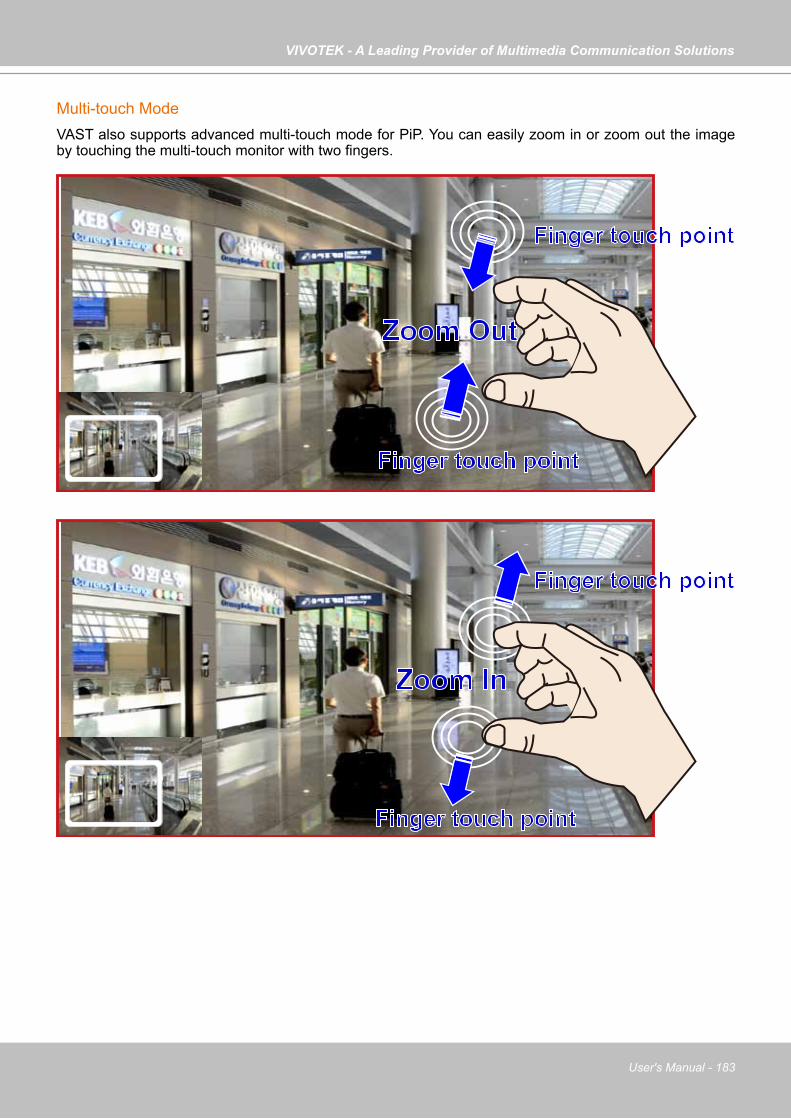
VIVOTEK - A Leading Provider of Multimedia Communication Solutions
User's Manual - 183
Multi-touch ModeVAST also supports advanced multi-touch mode for PiP. You can easily zoom in or zoom out the image by touching the multi-touch monitor with two fingers.
Zoom Out
Finger touch point
Finger touch point
Zoom In
Finger touch point
Finger touch point
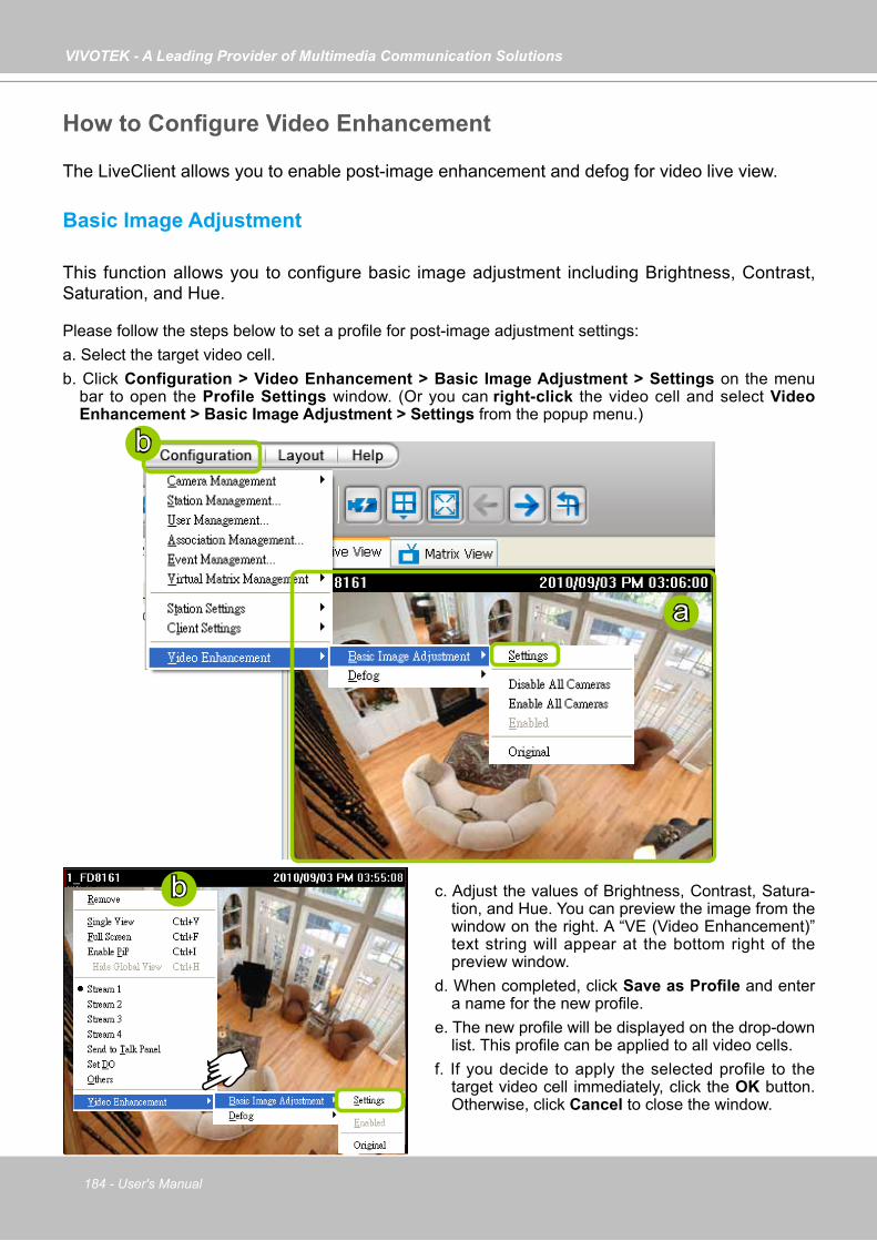
VIVOTEK - A Leading Provider of Multimedia Communication Solutions
184 - User's Manual
How to Configure Video Enhancement
The LiveClient allows you to enable post-image enhancement and defog for video live view.
Basic Image Adjustment
This function allows you to configure basic image adjustment including Brightness, Contrast, Saturation, and Hue.
Please follow the steps below to set a profile for post-image adjustment settings:a. Select the target video cell.b. Click Configuration > Video Enhancement > Basic Image Adjustment > Settings on the menu
bar to open the Profile Settings window. (Or you can right-click the video cell and select Video Enhancement > Basic Image Adjustment > Settings from the popup menu.)
a
b
b c. Adjust the values of Brightness, Contrast, Satura-tion, and Hue. You can preview the image from the window on the right. A “VE (Video Enhancement)” text string will appear at the bottom right of the preview window.
d. When completed, click Save as Profile and enter a name for the new profile.
e. The new profile will be displayed on the drop-down list. This profile can be applied to all video cells.
f. If you decide to apply the selected profile to the target video cell immediately, click the OK button. Otherwise, click Cancel to close the window.
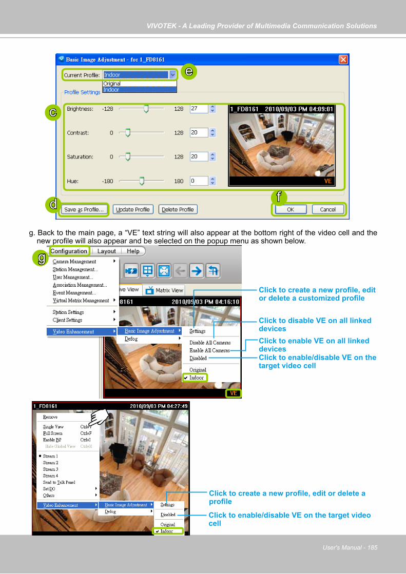
VIVOTEK - A Leading Provider of Multimedia Communication Solutions
User's Manual - 185
g. Back to the main page, a “VE” text string will also appear at the bottom right of the video cell and the new profile will also appear and be selected on the popup menu as shown below.
c
e
fd
g
Click to create a new profile, edit or delete a customized profile
Click to disable VE on all linked devices Click to enable VE on all linked devices Click to enable/disable VE on the target video cell
Click to create a new profile, edit or delete a profile
Click to enable/disable VE on the target video cell

VIVOTEK - A Leading Provider of Multimedia Communication Solutions
186 - User's Manual
Defog
This function allows you to configure post-image defog.
Apply a Preset Defog ProfilePlease follow the steps below to set post-image defog settings:a. Select the target video cell.b. Click Configuration > Video Enhancement > Defog or right-click the video cell and select Video
Enhancement > Defog. c. There are some preset profiles for you to apply to the target video cell. You can select one from the list
accoding to the environment.
a
b
b
c
c
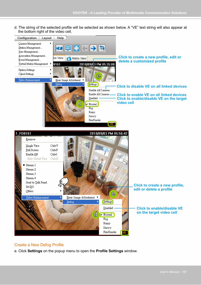
VIVOTEK - A Leading Provider of Multimedia Communication Solutions
User's Manual - 187
d. The string of the selected profile will be selected as shown below. A “VE” text string will also appear at the bottom right of the video cell.
Create a New Defog Profilee. Click Settings on the popup menu to open the Profile Settings window.
d
d
Click to create a new profile, edit or delete a customized profile
Click to disable VE on all linked devices
Click to enable VE on all linked devices Click to enable/disable VE on the target video cell
e
e
Click to enable/disable VE on the target video cell
Click to create a new profile, edit or delete a profile
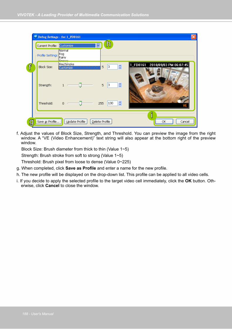
VIVOTEK - A Leading Provider of Multimedia Communication Solutions
188 - User's Manual
f. Adjust the values of Block Size, Strength, and Threshold. You can preview the image from the right window. A “VE (Video Enhancement)” text string will also appear at the bottom right of the preview window.
Block Size: Brush diameter from thick to thin (Value 1~5) Strength: Brush stroke from soft to strong (Value 1~5) Threshold: Brush pixel from loose to dense (Value 0~225)g. When completed, click Save as Profile and enter a name for the new profile.h. The new profile will be displayed on the drop-down list. This profile can be applied to all video cells.i. If you decide to apply the selected profile to the target video cell immediately, click the OK button. Oth-
erwise, click Cancel to close the window.
f
h
ig
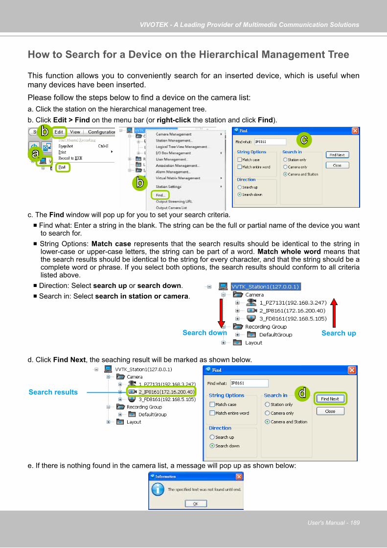
VIVOTEK - A Leading Provider of Multimedia Communication Solutions
User's Manual - 189
How to Search for a Device on the Hierarchical Management Tree
This function allows you to conveniently search for an inserted device, which is useful when many devices have been inserted.Please follow the steps below to find a device on the camera list:a. Click the station on the hierarchical management tree.b. Click Edit > Find on the menu bar (or right-click the station and click Find).
c. The Find window will pop up for you to set your search criteria. Find what: Enter a string in the blank. The string can be the full or partial name of the device you want
to search for. String Options: Match case represents that the search results should be identical to the string in
lower-case or upper-case letters, the string can be part of a word. Match whole word means that the search results should be identical to the string for every character, and that the string should be a complete word or phrase. If you select both options, the search results should conform to all criteria listed above.
Direction: Select search up or search down. Search in: Select search in station or camera.
d. Click Find Next, the seaching result will be marked as shown below.
e. If there is nothing found in the camera list, a message will pop up as shown below:
Search upSearch down
a
b c
Search results d
b
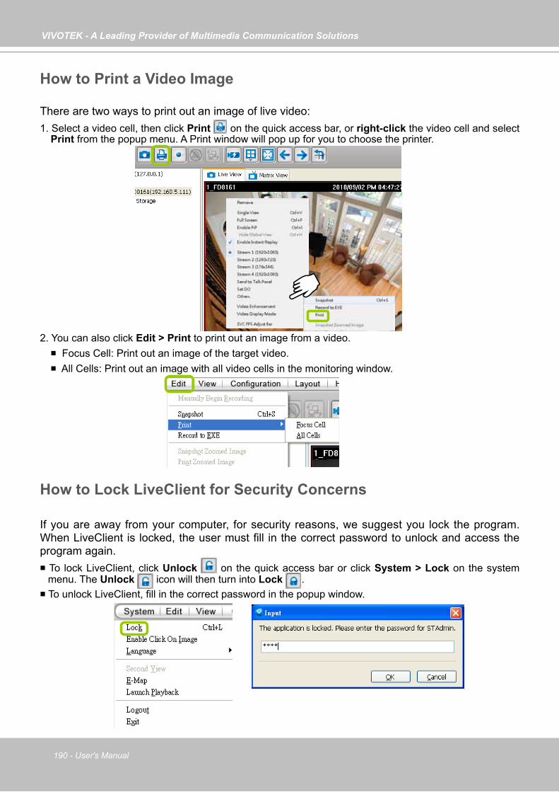
VIVOTEK - A Leading Provider of Multimedia Communication Solutions
190 - User's Manual
How to Print a Video Image
There are two ways to print out an image of live video:1. Select a video cell, then click Print on the quick access bar, or right-click the video cell and select
Print from the popup menu. A Print window will pop up for you to choose the printer.
2. You can also click Edit > Print to print out an image from a video. Focus Cell: Print out an image of the target video. All Cells: Print out an image with all video cells in the monitoring window.
How to Lock LiveClient for Security Concerns
If you are away from your computer, for security reasons, we suggest you lock the program. When LiveClient is locked, the user must fill in the correct password to unlock and access the program again. To lock LiveClient, click Unlock on the quick access bar or click System > Lock on the system
menu. The Unlock icon will then turn into Lock . To unlock LiveClient, fill in the correct password in the popup window.
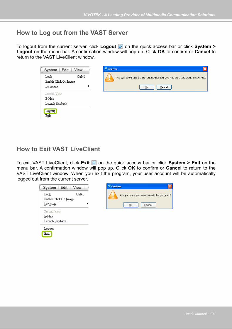
VIVOTEK - A Leading Provider of Multimedia Communication Solutions
User's Manual - 191
How to Log out from the VAST Server
To logout from the current server, click Logout on the quick access bar or click System > Logout on the menu bar. A confirmation window will pop up. Click OK to confirm or Cancel to return to the VAST LiveClient window.
How to Exit VAST LiveClient
To exit VAST LiveClient, click Exit on the quick access bar or click System > Exit on the menu bar. A confirmation window will pop up. Click OK to confirm or Cancel to return to the VAST LiveClient window. When you exit the program, your user account will be automatically logged out from the current server.
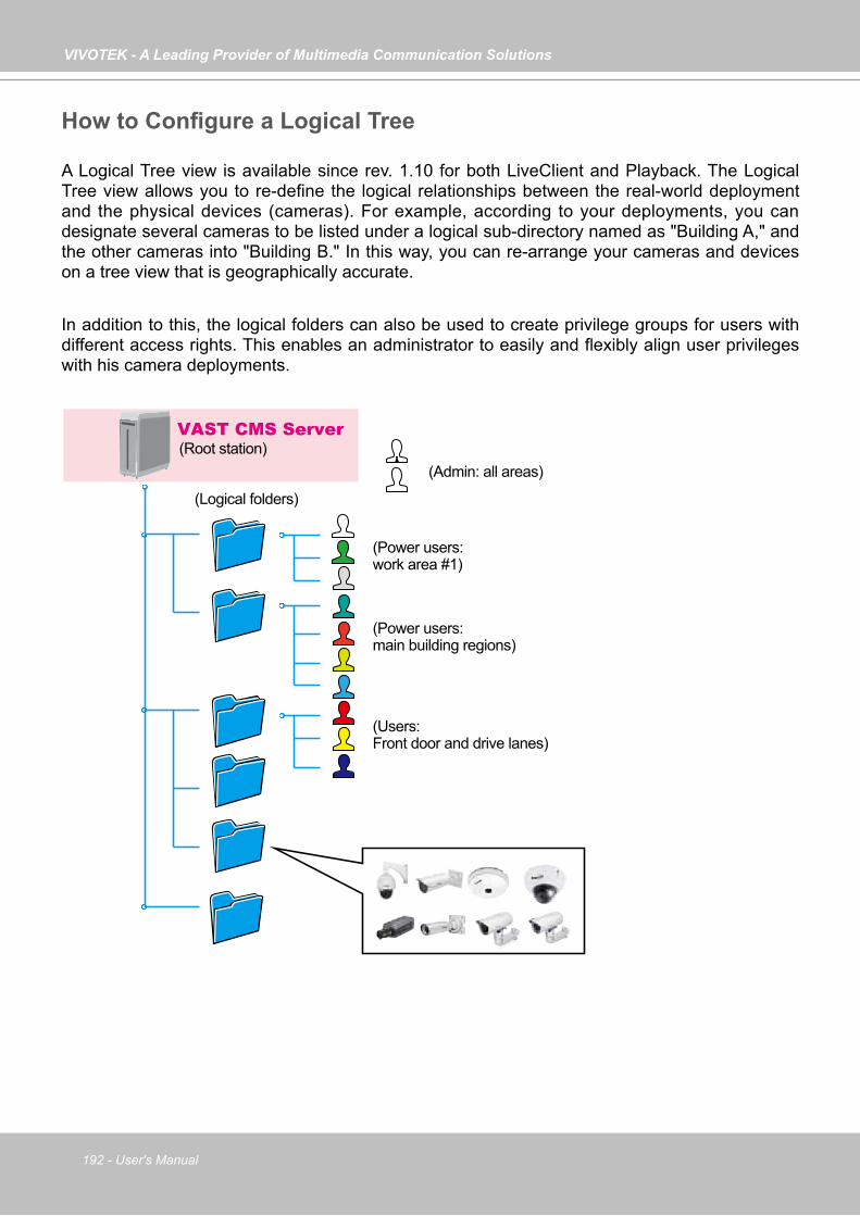
VIVOTEK - A Leading Provider of Multimedia Communication Solutions
192 - User's Manual
How to Configure a Logical Tree
A Logical Tree view is available since rev. 1.10 for both LiveClient and Playback. The Logical Tree view allows you to re-define the logical relationships between the real-world deployment and the physical devices (cameras). For example, according to your deployments, you can designate several cameras to be listed under a logical sub-directory named as "Building A," and the other cameras into "Building B." In this way, you can re-arrange your cameras and devices on a tree view that is geographically accurate.
In addition to this, the logical folders can also be used to create privilege groups for users with different access rights. This enables an administrator to easily and flexibly align user privileges with his camera deployments.
(Root station)VAST CMS Server
(Admin: all areas)
(Power users: main building regions)
(Logical folders)
(Users: Front door and drive lanes)
(Power users: work area #1)
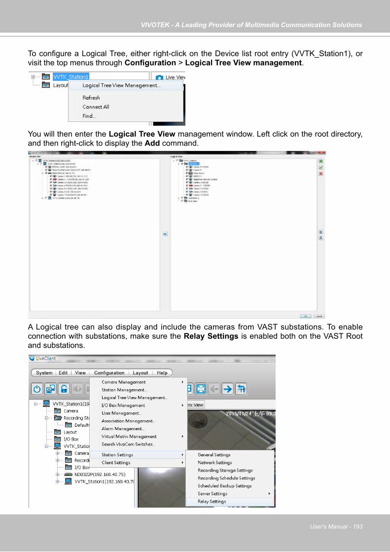
VIVOTEK - A Leading Provider of Multimedia Communication Solutions
User's Manual - 193
To configure a Logical Tree, either right-click on the Device list root entry (VVTK_Station1), or visit the top menus through Configuration > Logical Tree View management.
You will then enter the Logical Tree View management window. Left click on the root directory, and then right-click to display the Add command.
A Logical tree can also display and include the cameras from VAST substations. To enable connection with substations, make sure the Relay Settings is enabled both on the VAST Root and substations.
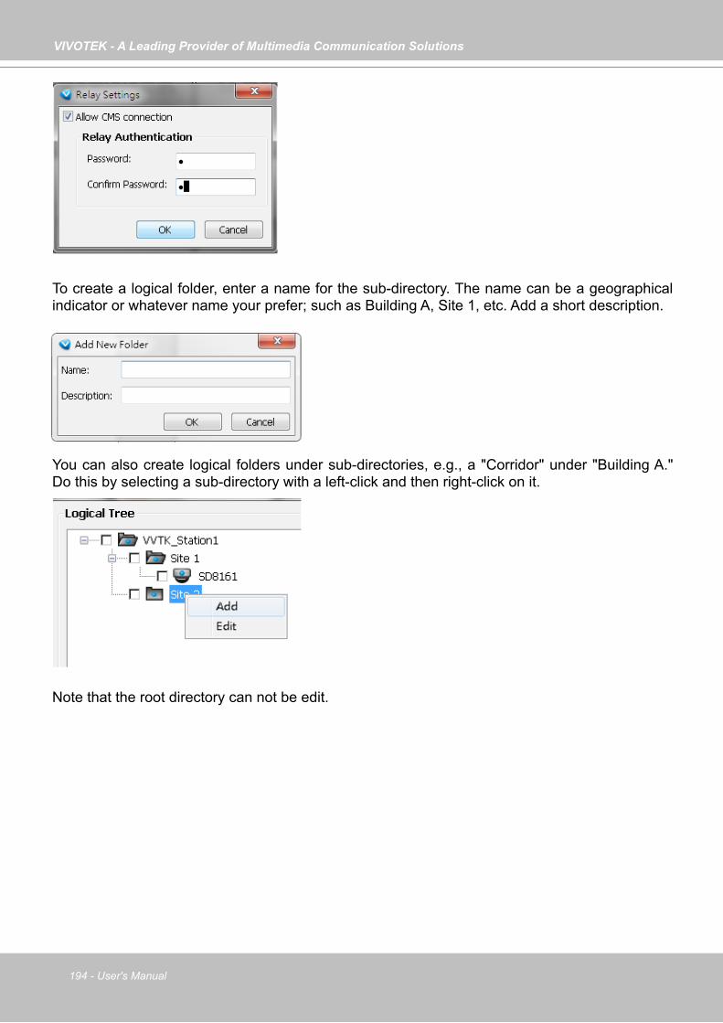
VIVOTEK - A Leading Provider of Multimedia Communication Solutions
194 - User's Manual
You can also create logical folders under sub-directories, e.g., a "Corridor" under "Building A." Do this by selecting a sub-directory with a left-click and then right-click on it.
To create a logical folder, enter a name for the sub-directory. The name can be a geographical indicator or whatever name your prefer; such as Building A, Site 1, etc. Add a short description.
Note that the root directory can not be edit.
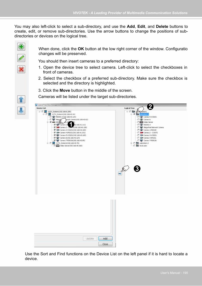
VIVOTEK - A Leading Provider of Multimedia Communication Solutions
User's Manual - 195
You may also left-click to select a sub-directory, and use the Add, Edit, and Delete buttons to create, edit, or remove sub-directories. Use the arrow buttons to change the positions of sub-directories or devices on the logical tree.
When done, click the OK button at the low right corner of the window. Configuratio changes will be preserved.
1
2
3
You should then insert cameras to a preferred directory: 1. Open the device tree to select camera. Left-click to select the checkboxes in
front of cameras. 2. Select the checkbox of a preferred sub-directory. Make sure the checkbox is
selected and the directory is highlighted.
Use the Sort and Find functions on the Device List on the left panel if it is hard to locate a device.
3. Click the Move button in the middle of the screen. Cameras will be listed under the target sub-directories.
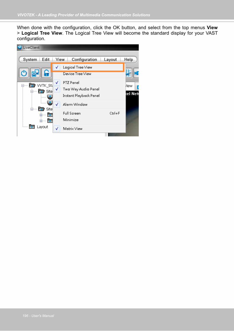
VIVOTEK - A Leading Provider of Multimedia Communication Solutions
196 - User's Manual
When done with the configuration, click the OK button, and select from the top menus View > Logical Tree View. The Logical Tree View will become the standard display for your VAST configuration.
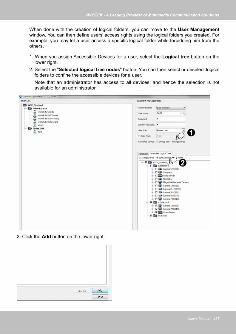
VIVOTEK - A Leading Provider of Multimedia Communication Solutions
User's Manual - 197
When done with the creation of logical folders, you can move to the User Management window. You can then define users' access rights using the logical folders you created. For example, you may let a user access a specific logical folder while forbidding him from the others.
1
2
1. When you assign Accessible Devices for a user, select the Logical tree button on the lower right.
2. Select the "Selected logical tree nodes" button. You can then select or deselect logical folders to confine the accessible devices for a user. Note that an administrator has access to all devices, and hence the selection is not available for an administrator.
3. Click the Add button on the lower right.
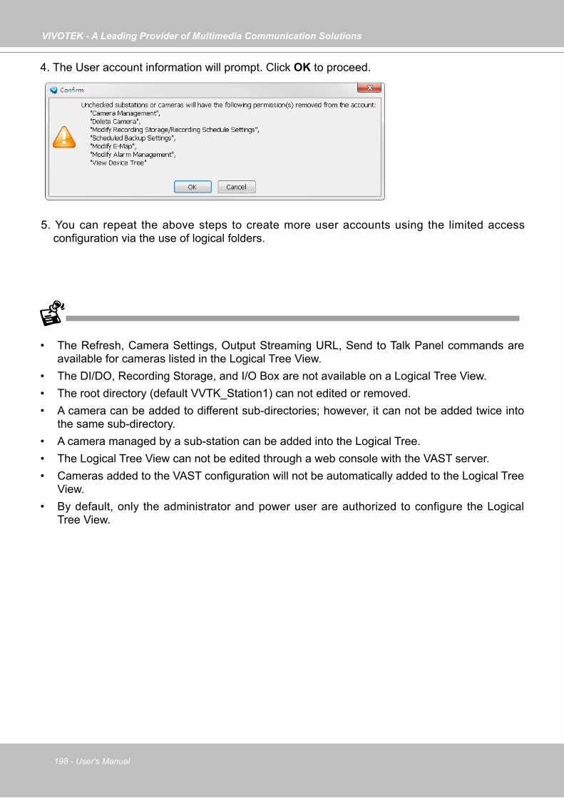
VIVOTEK - A Leading Provider of Multimedia Communication Solutions
198 - User's Manual
4. The User account information will prompt. Click OK to proceed.
• The Refresh, Camera Settings, Output Streaming URL, Send to Talk Panel commands are available for cameras listed in the Logical Tree View.
• The DI/DO, Recording Storage, and I/O Box are not available on a Logical Tree View. • The root directory (default VVTK_Station1) can not edited or removed. • A camera can be added to different sub-directories; however, it can not be added twice into
the same sub-directory. • A camera managed by a sub-station can be added into the Logical Tree. • The Logical Tree View can not be edited through a web console with the VAST server. • Cameras added to the VAST configuration will not be automatically added to the Logical Tree
View. • By default, only the administrator and power user are authorized to configure the Logical
Tree View.
5. You can repeat the above steps to create more user accounts using the limited access configuration via the use of logical folders.
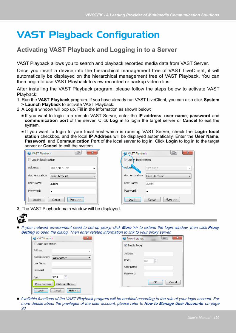
VIVOTEK - A Leading Provider of Multimedia Communication Solutions
User's Manual - 199
VAST Playback ConfigurationActivating VAST Playback and Logging in to a Server
VAST Playback allows you to search and playback recorded media data from VAST Server.Once you insert a device into the hierarchical management tree of VAST LiveClient, it will automatically be displayed on the hierarchical management tree of VAST Playback. You can then begin to use VAST Playback to view recorded or backup video clips.After installing the VAST Playback program, please follow the steps below to activate VAST Playback:1. Run the VAST Playback program. If you have already run VAST LiveClient, you can also click System
> Launch Playback to activate VAST Playback.2. A Login window will pop up. Fill in the information as shown below: If you want to login to a remote VAST Server, enter the IP address, user name, password and
communication port of the server. Click Log in to login the target server or Cancel to exit the system.
If you want to login to your local host which is running VAST Server, check the Login local station checkbox, and the local IP Address will be displayed automatically. Enter the User Name, Password, and Communication Port of the local server to log in. Click Login to log in to the target server or Cancel to exit the system.
3. The VAST Playback main window will be displayed.
If your network environment need to set up proxy, click More >> to extend the login window, then click Proxy Setting to open the dialog. Then enter related information to link to your proxy server.
Available functions of the VAST Playback program will be enabled according to the role of your login account. For more details about the privileges of the user account, please refer to How to Manage User Accounts on page 90.

VIVOTEK - A Leading Provider of Multimedia Communication Solutions
200 - User's Manual
VAST Playback User Interface
A. Menu bar B. Quick access bar C. Query panel (Browsing / Time search / Bookmark search /Event search / Alarm search / Log viewer) D. Status panel E. Recorded video playback window F. Playback control panel G. Video clips list
Menu Bar
Status Panel
Menu Item Drop-down Options
System Lock / Language / Launch LiveClient / Logout / Exit
Edit Snapshot / Print / Snapshot zoomed image / Print zoomed image / Find
ViewLogical Tree View / Device Tree View / Backup Status /Exporting Status / Browsing / Time Search / Event Search / Bookmark search / Alarm search / Log Viewer / Full Screen / Minimize / Query Panel / Video Clips List
Configuration Client Settings (Snapshot Settings / Export Settings / View Settings / Proxy Settings / General Settings / PiP Settings)
Layout Change Layout
Help About
User NameStation Name (IP Address)Login Time (yyyy-mm-dd hh:mm:ss)Current Time (yyyy-mm-dd hh:mm:ss)CPU and memory usage in percentage
G
D
A
E
B
C
F
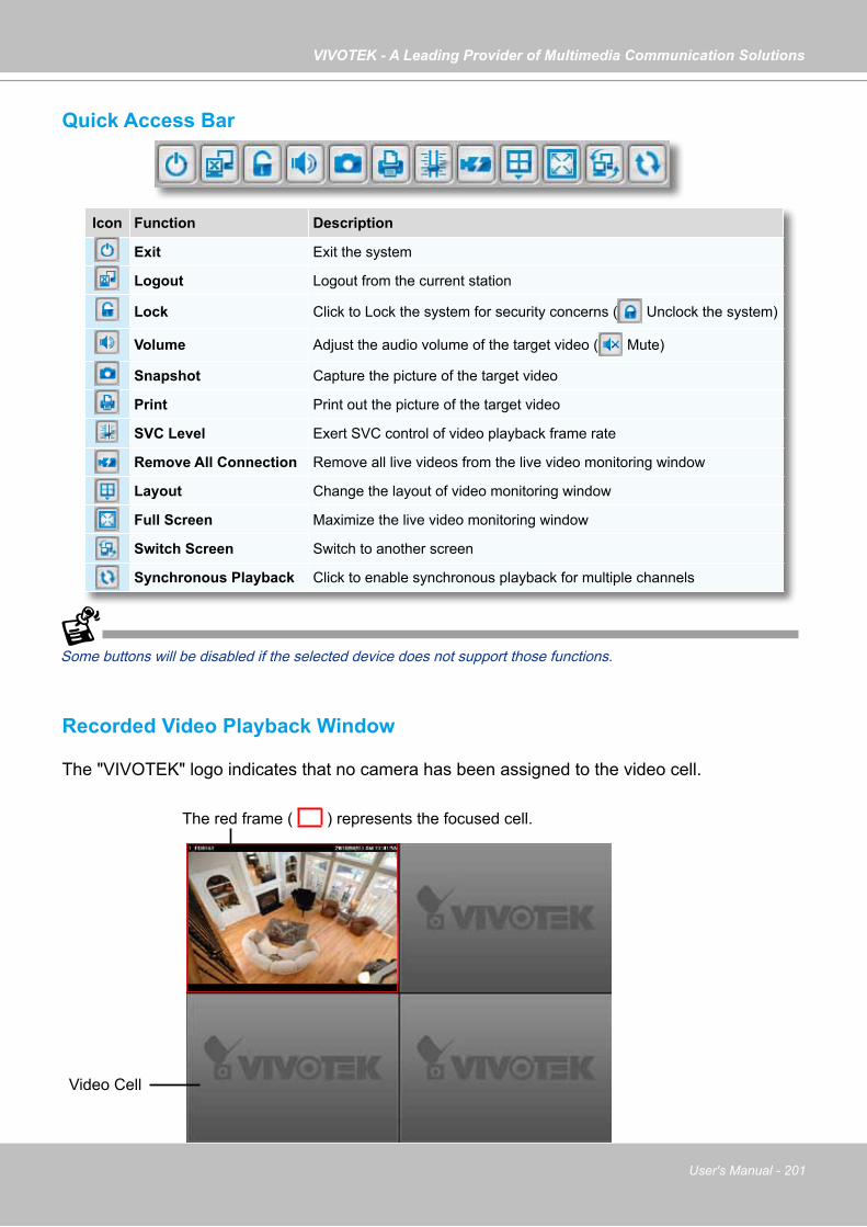
VIVOTEK - A Leading Provider of Multimedia Communication Solutions
User's Manual - 201
Quick Access Bar
Some buttons will be disabled if the selected device does not support those functions.
Recorded Video Playback Window
The "VIVOTEK" logo indicates that no camera has been assigned to the video cell.
Icon Function Description
Exit Exit the system
Logout Logout from the current station
Lock Click to Lock the system for security concerns ( Unclock the system)
Volume Adjust the audio volume of the target video ( Mute)
Snapshot Capture the picture of the target video
Print Print out the picture of the target video
SVC Level Exert SVC control of video playback frame rate
Remove All Connection Remove all live videos from the live video monitoring window
Layout Change the layout of video monitoring window
Full Screen Maximize the live video monitoring window
Switch Screen Switch to another screen
Synchronous Playback Click to enable synchronous playback for multiple channels
The red frame ( ) represents the focused cell.
Video Cell
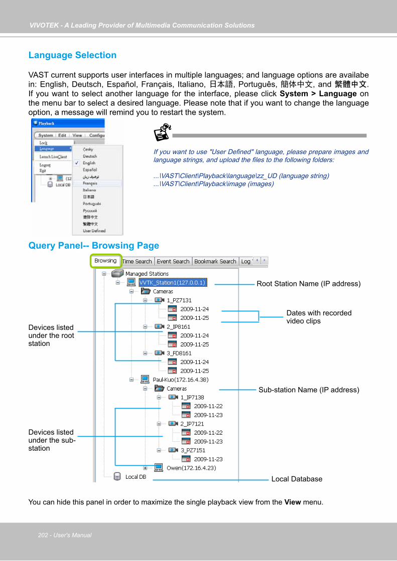
VIVOTEK - A Leading Provider of Multimedia Communication Solutions
202 - User's Manual
Language Selection
VAST current supports user interfaces in multiple languages; and language options are availabe in: English, Deutsch, Español, Français, Italiano, 日本語, Português, 簡体中文, and 繁體中文. If you want to select another language for the interface, please click System > Language on the menu bar to select a desired language. Please note that if you want to change the language option, a message will remind you to restart the system.
Query Panel-- Browsing Page
Dates with recorded video clips
Devices listed under the root station
If you want to use "User Defined" language, please prepare images and language strings, and upload the files to the following folders:
...\VAST\Client\Playback\language\zz_UD (language string)
...\VAST\Client\Playback\image (images)
Local Database
Root Station Name (IP address)
Sub-station Name (IP address)
Devices listed under the sub-station
You can hide this panel in order to maximize the single playback view from the View menu.
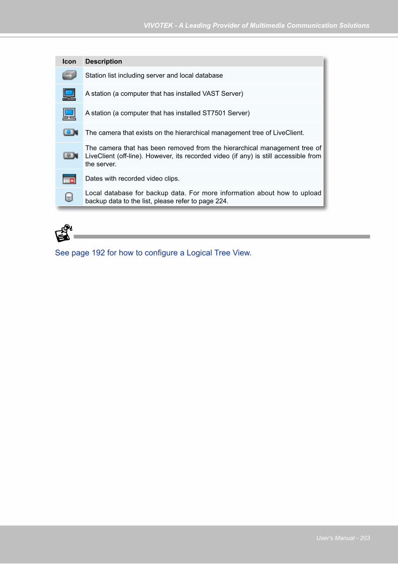
VIVOTEK - A Leading Provider of Multimedia Communication Solutions
User's Manual - 203
Icon Description
Station list including server and local database
A station (a computer that has installed VAST Server)
A station (a computer that has installed ST7501 Server)
The camera that exists on the hierarchical management tree of LiveClient.
The camera that has been removed from the hierarchical management tree of LiveClient (off-line). However, its recorded video (if any) is still accessible from the server.
Dates with recorded video clips.
Local database for backup data. For more information about how to upload backup data to the list, please refer to page 224.
See page 192 for how to configure a Logical Tree View.
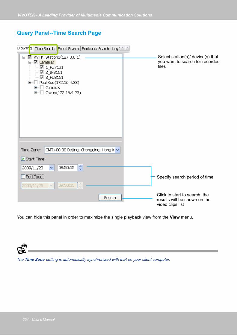
VIVOTEK - A Leading Provider of Multimedia Communication Solutions
204 - User's Manual
Query Panel--Time Search Page
The Time Zone setting is automatically synchronized with that on your client computer.
Select station(s)/ device(s) that you want to search for recorded files
Specify search period of time
Click to start to search, the results will be shown on the video clips list
You can hide this panel in order to maximize the single playback view from the View menu.
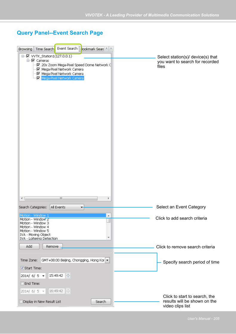
VIVOTEK - A Leading Provider of Multimedia Communication Solutions
User's Manual - 205
Select an Event Category
Specify search period of time
Click to start to search, the results will be shown on the video clips list
Click to add search criteria
Query Panel--Event Search Page
Click to remove search criteria
Select station(s)/ device(s) that you want to search for recorded files
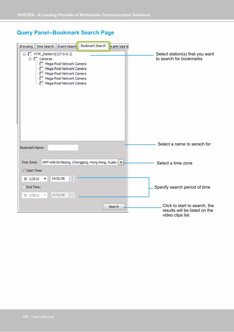
VIVOTEK - A Leading Provider of Multimedia Communication Solutions
206 - User's Manual
Query Panel--Bookmark Search Page
Select a name to serach for
Select a time zone
Specify search period of time
Click to start to search, the results will be listed on the video clips list
Select station(s) that you want to search for bookmarks

VIVOTEK - A Leading Provider of Multimedia Communication Solutions
User's Manual - 207
Query Panel--Alarm Search Page
Click to configure the search conditions
Select a time zone
Specify search period of time
Click to start to search, the results will be listed on the video clips list
Select station(s) that you want to search for bookmarks
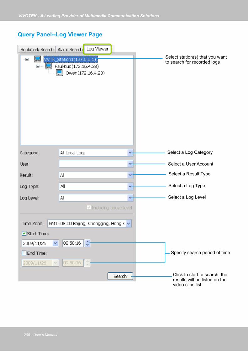
VIVOTEK - A Leading Provider of Multimedia Communication Solutions
208 - User's Manual
Query Panel--Log Viewer Page
Select a Log Category
Select a User Account
Select a Result Type
Select a Log Type
Select a Log Level
Specify search period of time
Click to start to search, the results will be listed on the video clips list
Select station(s) that you want to search for recorded logs
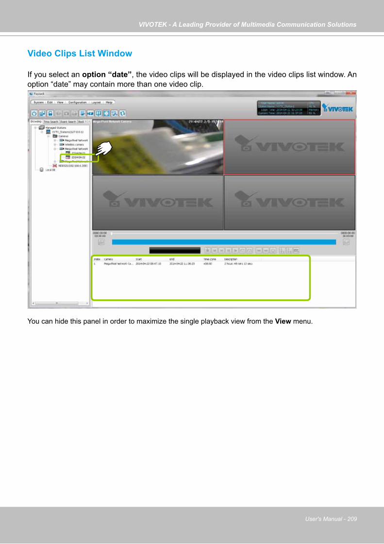
VIVOTEK - A Leading Provider of Multimedia Communication Solutions
User's Manual - 209
Video Clips List Window
If you select an option “date”, the video clips will be displayed in the video clips list window. An option “date” may contain more than one video clip.
You can hide this panel in order to maximize the single playback view from the View menu.
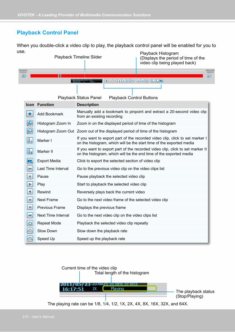
VIVOTEK - A Leading Provider of Multimedia Communication Solutions
210 - User's Manual
Playback Control Panel
When you double-click a video clip to play, the playback control panel will be enabled for you to use.
Icon Function Description
Add Bookmark Manually add a bookmark to pinpoint and extract a 20-second video clip from an existing recording
Histogram Zoom In Zoom in on the displayed period of time of the histogram
Histogram Zoom Out Zoom out of the displayed period of time of the histogram
Marker I If you want to export part of the recorded video clip, click to set marker I on the histogram, which will be the start time of the exported media
Marker II If you want to export part of the recorded video clip, click to set marker II on the histogram, which will be the end time of the exported media
Export Media Click to export the selected section of video clip
Last Time Interval Go to the previous video clip on the video clips list
Pause Pause playback the selected video clip
Play Start to playback the selected video clip
Rewind Reversely plays back the current video
Next Frame Go to the next video frame of the selected video clip
Previous Frame Displays the previous frame
Next Time Interval Go to the next video clip on the video clips list
Repeat Mode Playback the selected video clip repeatly
Slow Down Slow down the playback rate
Speed Up Speed up the playback rate
Current time of the video clipTotal length of the histogram
The playback status (Stop/Playing)
The playing rate can be 1/8, 1/4, 1/2, 1X, 2X, 4X, 8X, 16X, 32X, and 64X.
Playback Timeline Slider
Playback Status Panel Playback Control Buttons
Playback Histogram(Displays the period of time of the video clip being played back)
VIVOTEK - A Leading Provider of Multimedia Communication Solutions
User's Manual - 211
Rewind
The Rewind function enables users to reversely playback from a specific point in time on a video playback window. Once the occurrence of an event is ensured, this function can facilitate the process of finding the evidences that appeared before the occurrence.
The Rewind function also applies to the Synchronous Playback mode. The following also apply:1. The maximum playback speed is 64x. (I-frame only when speed is higher than 16x)2. When you pull the time slider during the Rewind playback, short interruptions may occur. 3. When switching from the playback mode to the Rewind playback, the playback speed remains
the same. The same applies when switching from Rewind to the playback mode.
Limitations:
1. Short delays may occur when switching from playback to rewind, due to limitations by the hard disk access speed and network speed.
2. When doing the forward playback, the previous frame function is not available. When doing the rewind playback, the next frame function is not available.
3. The Rewind playback on multiple streams requires system performance resources.
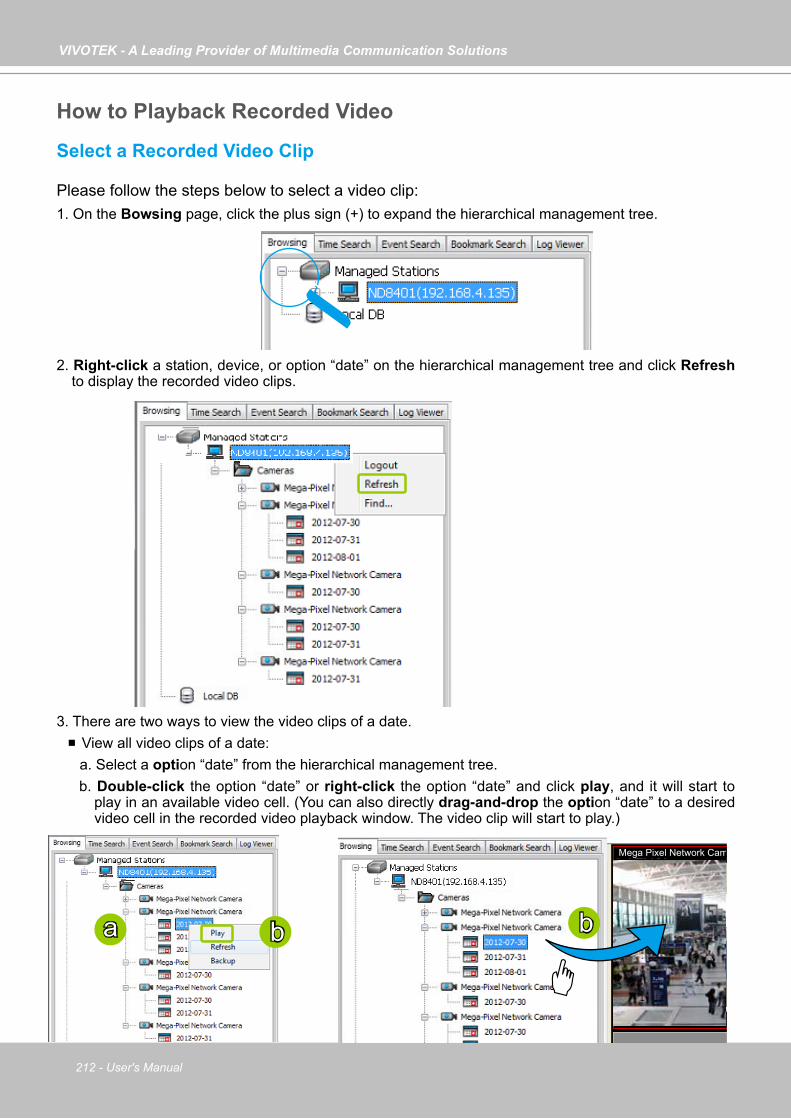
VIVOTEK - A Leading Provider of Multimedia Communication Solutions
212 - User's Manual
How to Playback Recorded Video
Select a Recorded Video Clip
Please follow the steps below to select a video clip:1. On the Bowsing page, click the plus sign (+) to expand the hierarchical management tree.
2. Right-click a station, device, or option “date” on the hierarchical management tree and click Refresh to display the recorded video clips.
3. There are two ways to view the video clips of a date. View all video clips of a date:
a. Select a option “date” from the hierarchical management tree.b. Double-click the option “date” or right-click the option “date” and click play, and it will start to
play in an available video cell. (You can also directly drag-and-drop the option “date” to a desired video cell in the recorded video playback window. The video clip will start to play.)
Mega Pixel Network Camera 2012/07/31PM
a b b
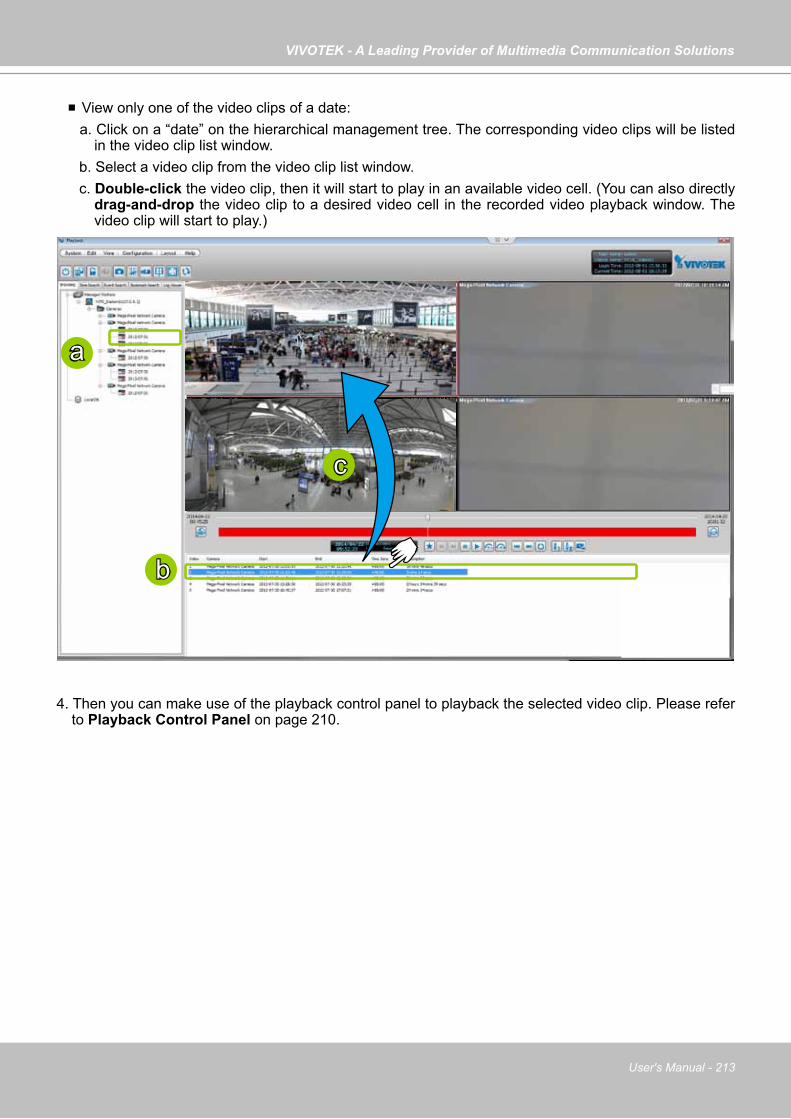
VIVOTEK - A Leading Provider of Multimedia Communication Solutions
User's Manual - 213
View only one of the video clips of a date:a. Click on a “date” on the hierarchical management tree. The corresponding video clips will be listed
in the video clip list window.b. Select a video clip from the video clip list window.c. Double-click the video clip, then it will start to play in an available video cell. (You can also directly
drag-and-drop the video clip to a desired video cell in the recorded video playback window. The video clip will start to play.)
4. Then you can make use of the playback control panel to playback the selected video clip. Please refer to Playback Control Panel on page 210.
a
b
c
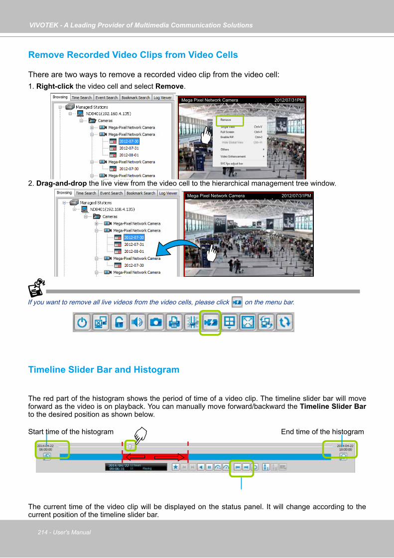
VIVOTEK - A Leading Provider of Multimedia Communication Solutions
214 - User's Manual
Remove Recorded Video Clips from Video Cells
There are two ways to remove a recorded video clip from the video cell: 1. Right-click the video cell and select Remove.
2. Drag-and-drop the live view from the video cell to the hierarchical management tree window.
If you want to remove all live videos from the video cells, please click on the menu bar.
Timeline Slider Bar and Histogram
The red part of the histogram shows the period of time of a video clip. The timeline slider bar will move forward as the video is on playback. You can manually move forward/backward the Timeline Slider Bar to the desired position as shown below.
The current time of the video clip will be displayed on the status panel. It will change according to the current position of the timeline slider bar.
Mega Pixel Network Camera 2012/07/31PM
Mega Pixel Network Camera 2012/07/31PM
Start time of the histogram End time of the histogram
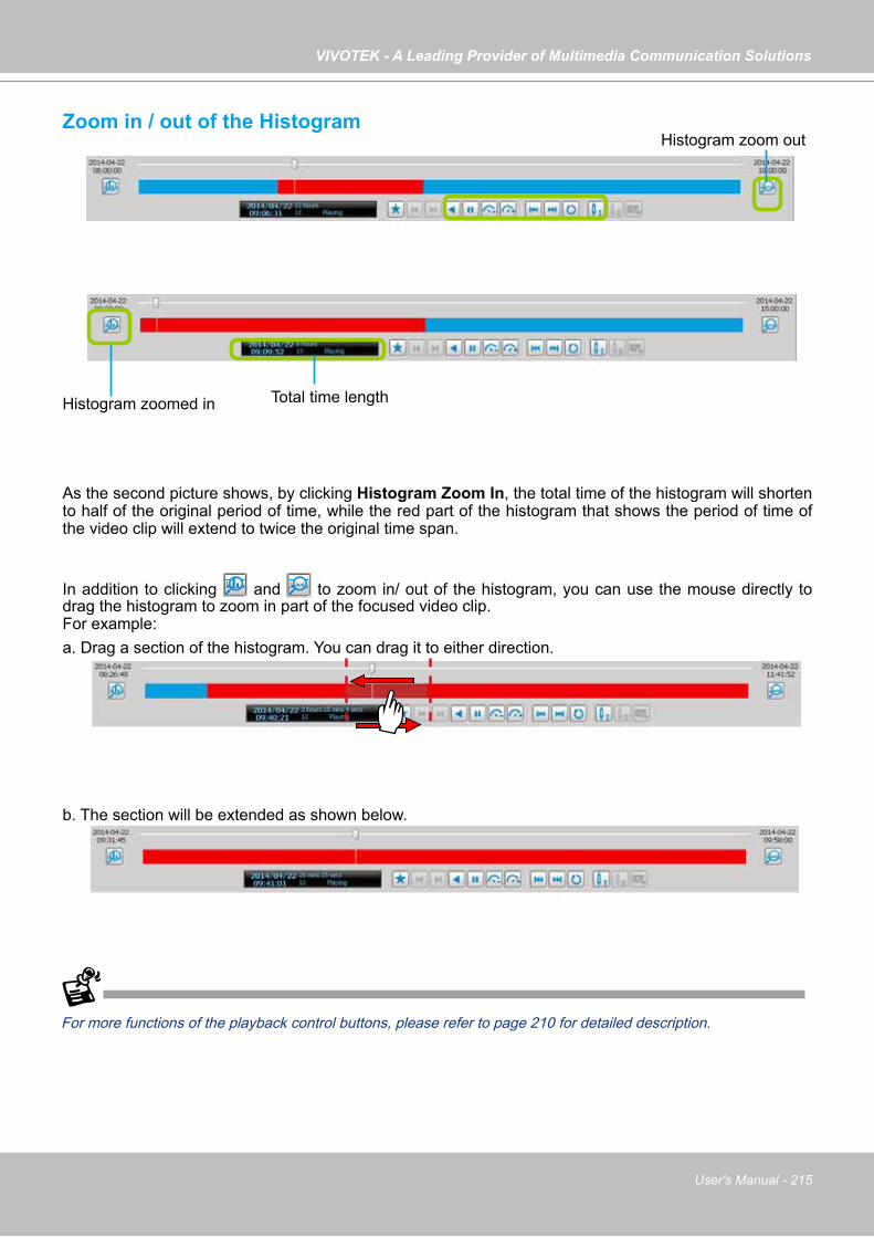
VIVOTEK - A Leading Provider of Multimedia Communication Solutions
User's Manual - 215
Zoom in / out of the Histogram
As the second picture shows, by clicking Histogram Zoom In, the total time of the histogram will shorten to half of the original period of time, while the red part of the histogram that shows the period of time of the video clip will extend to twice the original time span.
In addition to clicking and to zoom in/ out of the histogram, you can use the mouse directly to drag the histogram to zoom in part of the focused video clip.For example:a. Drag a section of the histogram. You can drag it to either direction.
b. The section will be extended as shown below.
For more functions of the playback control buttons, please refer to page 210 for detailed description.
Histogram zoomed in
Histogram zoom out
Total time length

VIVOTEK - A Leading Provider of Multimedia Communication Solutions
216 - User's Manual
Synchronous Playback
VIVOTEK VAST Playback supports synchronous playback, which allows you to review up to 16-channel video clips simultaneously during the specific time point.Please follow the steps below to enable synchronous playback:a. Drag-and-drop the option “date”s to the video cells.
b. Drag the Timeline Slider Bar to the specific time point.c. Click the synchronous playback button on the quick access bar. The selected channel will start to
sychronously playback as shown below.
2012/07/31 11:02:03PM
2012/07/31 11:02:03PM
2012/07/31 11:02:03PM
2012/07/31 11:02:03PM
b
c
2012/07/31 11:02:03PM2012/07/31 11:02:03PM
2012/07/31 11:02:03PM
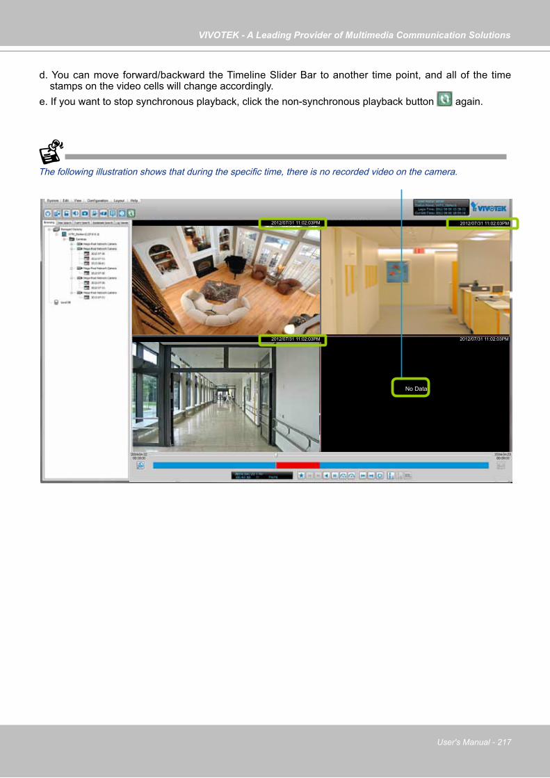
VIVOTEK - A Leading Provider of Multimedia Communication Solutions
User's Manual - 217
d. You can move forward/backward the Timeline Slider Bar to another time point, and all of the time stamps on the video cells will change accordingly.
e. If you want to stop synchronous playback, click the non-synchronous playback button again.
The following illustration shows that during the specific time, there is no recorded video on the camera.
2012/07/31 11:02:03PM
2012/07/31 11:02:03PM
2012/07/31 11:02:03PM
2012/07/31 11:02:03PM
No Data
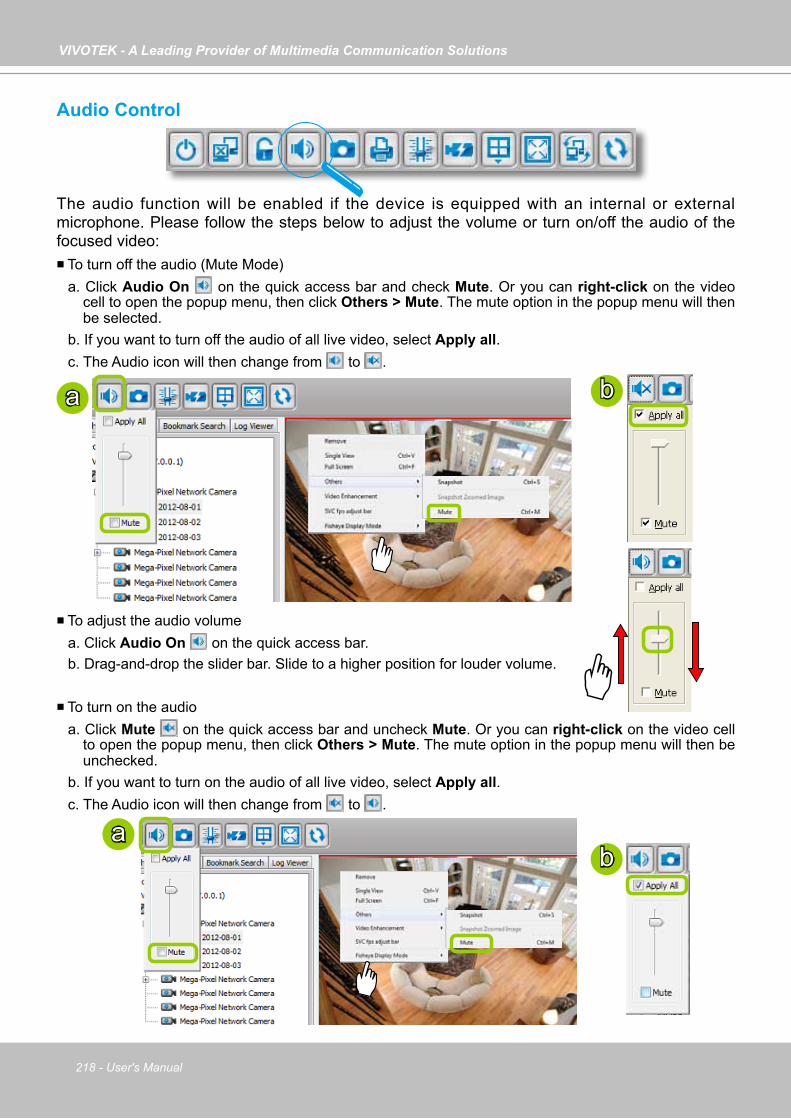
VIVOTEK - A Leading Provider of Multimedia Communication Solutions
218 - User's Manual
Audio Control
The audio function will be enabled if the device is equipped with an internal or external microphone. Please follow the steps below to adjust the volume or turn on/off the audio of the focused video: To turn off the audio (Mute Mode)
a. Click Audio On on the quick access bar and check Mute. Or you can right-click on the video cell to open the popup menu, then click Others > Mute. The mute option in the popup menu will then be selected.
b. If you want to turn off the audio of all live video, select Apply all. c. The Audio icon will then change from to .
To adjust the audio volumea. Click Audio On on the quick access bar.b. Drag-and-drop the slider bar. Slide to a higher position for louder volume.
To turn on the audioa. Click Mute on the quick access bar and uncheck Mute. Or you can right-click on the video cell
to open the popup menu, then click Others > Mute. The mute option in the popup menu will then be unchecked.
b. If you want to turn on the audio of all live video, select Apply all. c. The Audio icon will then change from to .
ba
ab

VIVOTEK - A Leading Provider of Multimedia Communication Solutions
User's Manual - 219
How to Change the Playback Layout
Changing the Layout of the Recorded Video Playback Window
VIVOTEK VAST Playback supports up to 16-CH simultaneous recorded video playback on a single monitor and allows you to change the layout of the recorded live video playback window based on the number of inserted devices.
Switch Video Channels
Drag-and-drop a video channel to another empty video window.
To switch two channels, drag-and-drop one view to the other, then the two channels will switch positions.
Configure Layout Mode
Click the Layout button on the quick access bar or click Layout > Change Layout on the menu bar. Select a desired layout mode and the layout window will change accordingly. Below we illustrate 6 types of layout modes:
Layout mode Description
1 x 1
2 x 2
1 + 53 x 3
1 + 124 x 4

VIVOTEK - A Leading Provider of Multimedia Communication Solutions
220 - User's Manual
Maximize/Minimize the Recorded Video Playback Window
Single View: to maxmize a video cell to the entire video playback window
Double-click the video cell, or right-click the video cell and selec Single View. The focused video will occupy the entire Playback window as shown below.
To restore to the original layout, double-click the video cell or right-click the video cell and uncheck Single View.
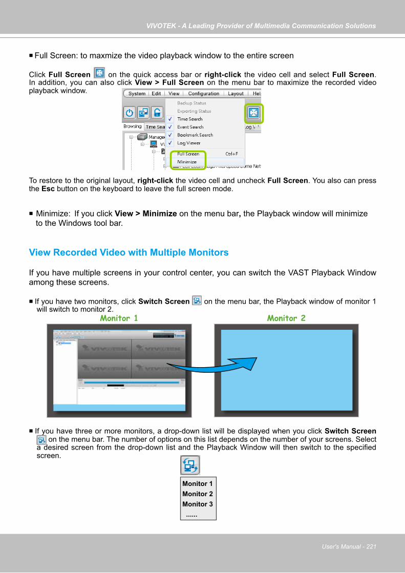
VIVOTEK - A Leading Provider of Multimedia Communication Solutions
User's Manual - 221
Full Screen: to maxmize the video playback window to the entire screen
Click Full Screen on the quick access bar or right-click the video cell and select Full Screen. In addition, you can also click View > Full Screen on the menu bar to maximize the recorded video playback window.
To restore to the original layout, right-click the video cell and uncheck Full Screen. You also can press the Esc button on the keyboard to leave the full screen mode.
Minimize: If you click View > Minimize on the menu bar, the Playback window will minimize to the Windows tool bar.
View Recorded Video with Multiple Monitors
If you have multiple screens in your control center, you can switch the VAST Playback Window among these screens.
If you have two monitors, click Switch Screen on the menu bar, the Playback window of monitor 1 will switch to monitor 2.
If you have three or more monitors, a drop-down list will be displayed when you click Switch Screen on the menu bar. The number of options on this list depends on the number of your screens. Select
a desired screen from the drop-down list and the Playback Window will then switch to the specified screen.
Monitor 1 Monitor 2
Monitor 1Monitor 2Monitor 3 ......
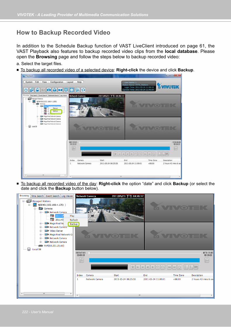
VIVOTEK - A Leading Provider of Multimedia Communication Solutions
222 - User's Manual
How to Backup Recorded Video
In addition to the Schedule Backup function of VAST LiveClient introduced on page 61, the VAST Playback also features to backup recorded video clips from the local database. Please open the Browsing page and follow the steps below to backup recorded video:a. Select the target files. To backup all recorded video of a selected device: Right-click the device and click Backup.
To backup all recorded video of the day: Right-click the option “date” and click Backup (or select the date and click the Backup button below).
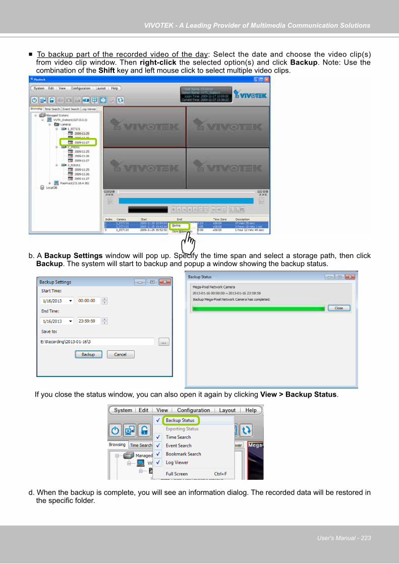
VIVOTEK - A Leading Provider of Multimedia Communication Solutions
User's Manual - 223
To backup part of the recorded video of the day: Select the date and choose the video clip(s) from video clip window. Then right-click the selected option(s) and click Backup. Note: Use the combination of the Shift key and left mouse click to select multiple video clips.
b. A Backup Settings window will pop up. Specify the time span and select a storage path, then click Backup. The system will start to backup and popup a window showing the backup status.
If you close the status window, you can also open it again by clicking View > Backup Status.
d. When the backup is complete, you will see an information dialog. The recorded data will be restored in the specific folder.

VIVOTEK - A Leading Provider of Multimedia Communication Solutions
224 - User's Manual
How to View Backup Files
The VAST Playback also allows users to playback backup files, including Schedule Backup by VAST LiveClient and Recorded Data Backup by VAST Playback.
Please follow the steps below to view backup files:a. Right-click Local DB and click Add.b. A Load Backup File window will pop up as shown below. Select the *.dif file to upload.
c. The following is an example of uploaded file, and you can double-click it or drag-and-drop it to a video cell to playback.
a
b

VIVOTEK - A Leading Provider of Multimedia Communication Solutions
User's Manual - 225
If you want to playback the backup files from the local database, you can also click Working Offline in the Login Window without the account information. The VAST Playback will launch as shown below.
You can upload backup files
No user account information required
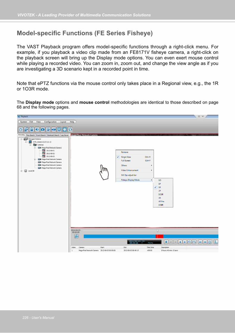
VIVOTEK - A Leading Provider of Multimedia Communication Solutions
226 - User's Manual
Model-specific Functions (FE Series Fisheye)
The VAST Playback program offers model-specific functions through a right-click menu. For example, if you playback a video clip made from an FE8171V fisheye camera, a right-click on the playback screen will bring up the Display mode options. You can even exert mouse control while playing a recorded video. You can zoom in, zoom out, and change the view angle as if you are investigating a 3D scenario kept in a recorded point in time.
Note that ePTZ functions via the mouse control only takes place in a Regional view, e.g., the 1R or 1O3R mode.
The Display mode options and mouse control methodologies are identical to those described on page 68 and the following pages.
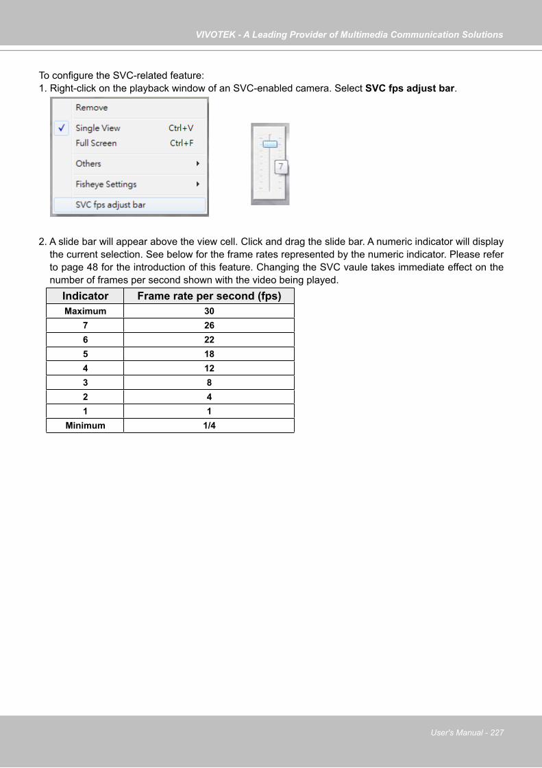
VIVOTEK - A Leading Provider of Multimedia Communication Solutions
User's Manual - 227
To configure the SVC-related feature:1. Right-click on the playback window of an SVC-enabled camera. Select SVC fps adjust bar.
2. A slide bar will appear above the view cell. Click and drag the slide bar. A numeric indicator will display the current selection. See below for the frame rates represented by the numeric indicator. Please refer to page 48 for the introduction of this feature. Changing the SVC vaule takes immediate effect on the number of frames per second shown with the video being played.
Indicator Frame rate per second (fps)Maximum 30
7 266 225 184 123 82 41 1
Minimum 1/4

VIVOTEK - A Leading Provider of Multimedia Communication Solutions
228 - User's Manual
How to Search for a Video Clip in a Specific Period of time
Please follow the steps below to use Time Search function:a. Open the Time Search page.
b. Select the target station(s)/device(s) that you want to search for video clips.c. Specify the time span. You can choose to set up the start time only, the end time only, or both the
start time and end time. The search results will only include the video clips within the time span. If you uncheck both the start time and end time, the search results will include all video clips recorded by the selected device(s).
d. Click Search to start time search.e. View the retrieved video clips.
Click here to move the focus to the current date
Click to select a yearClick to select a month from the drop-down list
You can manually enter a specific time.
a
c
e
d
b

VIVOTEK - A Leading Provider of Multimedia Communication Solutions
User's Manual - 229
How to Add a Bookmark
Bookmark is a convenient tagging function that allow your to pinpoint and extract a 20-second video clip from out of a video recording. When you see somehting of your interest while browsing through a recorded video, 1. Click on the Bookmark button, 2. Enter a name for the bookmark, such as "thief spotted." 3. You may enter a short description in the Description field. You may also search for the bookmarks you
created later on.
A bookmark comprises a video clip starting from 10 seconds of before and ends at 10 seconds after the point in time you selected.
Please refer to page 206 for how to search for bookmarks.

VIVOTEK - A Leading Provider of Multimedia Communication Solutions
230 - User's Manual
How to Search for Events
The VAST Playback program offers users an intuitive event search engine for retrieving video clips from the database of recorded videos based on different search criteria such as motion, IVA, or DI events. Please follow the steps below to search for recorded events:a. Open the Event Search page.
b. Select the target station(s)/device(s) that you want to search for events.c. Specify the Event Category. For detailed information, please refer to Select Event Category on the
following page.d. Specify the time span for event search. You can choose to set up the start time only, the end time
only, or both the start time and end time. The search results will only include the events within the time span. If you uncheck both the start time and end time, the search results will include all events from the selected device(s). Please refer to step c. on the previous page for detailed information.
e. Start event search. Please refer to page 234 for detailed information. f. View the retrieved video clips. Double-click on it or drag-and-drop it to the video cell. It will playback
in repeat mode. Note: The length of each video clip will depend on your settings of pre-event time & post-event time for
the recording storage. The default setting is 20 seconds. For more infromation, please refer to page 120 for detailed information.
b
c
d e
f
a
repeat mode
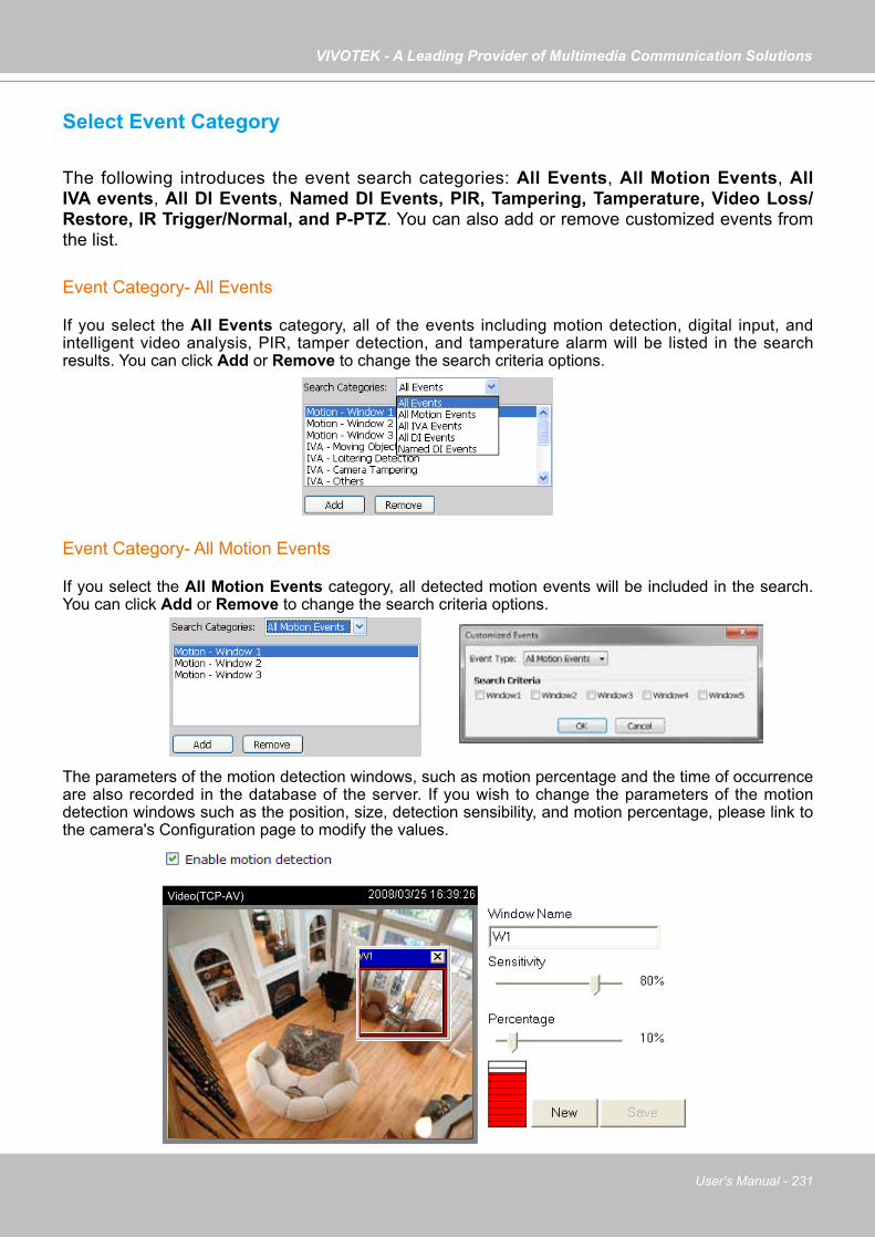
VIVOTEK - A Leading Provider of Multimedia Communication Solutions
User's Manual - 231
Select Event Category
The following introduces the event search categories: All Events, All Motion Events, All IVA events, All DI Events, Named DI Events, PIR, Tampering, Tamperature, Video Loss/Restore, IR Trigger/Normal, and P-PTZ. You can also add or remove customized events from the list.
Event Category- All Events
If you select the All Events category, all of the events including motion detection, digital input, and intelligent video analysis, PIR, tamper detection, and tamperature alarm will be listed in the search results. You can click Add or Remove to change the search criteria options.
Event Category- All Motion Events
If you select the All Motion Events category, all detected motion events will be included in the search. You can click Add or Remove to change the search criteria options.
The parameters of the motion detection windows, such as motion percentage and the time of occurrence are also recorded in the database of the server. If you wish to change the parameters of the motion detection windows such as the position, size, detection sensibility, and motion percentage, please link to the camera's Configuration page to modify the values.
Video(TCP-AV)
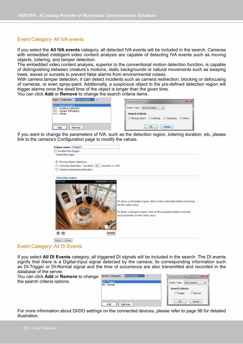
VIVOTEK - A Leading Provider of Multimedia Communication Solutions
232 - User's Manual
Event Category- All IVA events
If you select the All IVA events category, all detected IVA events will be included in the search. Cameras with embedded intelligent video content analysis are capable of detecting IVA events such as moving objects, loitering, and tamper detection. The embedded video content analysis, superior to the conventional motion detection function, is capable of distinguishing between creature’s motions, static backgrounds or natural movements such as swaying trees, waves or sunsets to prevent false alarms from environmental noises.With camera tamper detection, it can detect incidents such as camera redirection, blocking or defocusing of cameras, or even spray-paint. Additionally, a suspicious object in the pre-defined detection region will trigger alarms once the dwell time of the object is longer than the given time. You can click Add or Remove to change the search criteria items.
If you want to change the parameters of IVA, such as the detection region, loitering duration, etc, please link to the camera's Configuration page to modify the values.
Event Category- All DI Events
If you select All DI Events category, all triggered DI signals will be included in the search. The DI events signify that there is a Digital-Input signal detected by the camera; its corresponding information such as DI-Trigger or DI-Normal signal and the time of occurrence are also transmitted and recorded in the database of the server. You can click Add or Remove to change the search criteria options.
For more information about DI/DO settings on the connected devices, please refer to page 98 for detailed illustration.

VIVOTEK - A Leading Provider of Multimedia Communication Solutions
User's Manual - 233
Event Category- Named DI Events
This category allows you to select only Named DI Events--the DI device which you have renamed in the LiveClient. Please refer to Association Management on page 98 for more information about how to rename DI device.Click OK and fill in the name you want to search on the left window.
The new search criteria will be displayed in the search categories column as shown below.You can click Add or Remove to change the search criteria options.
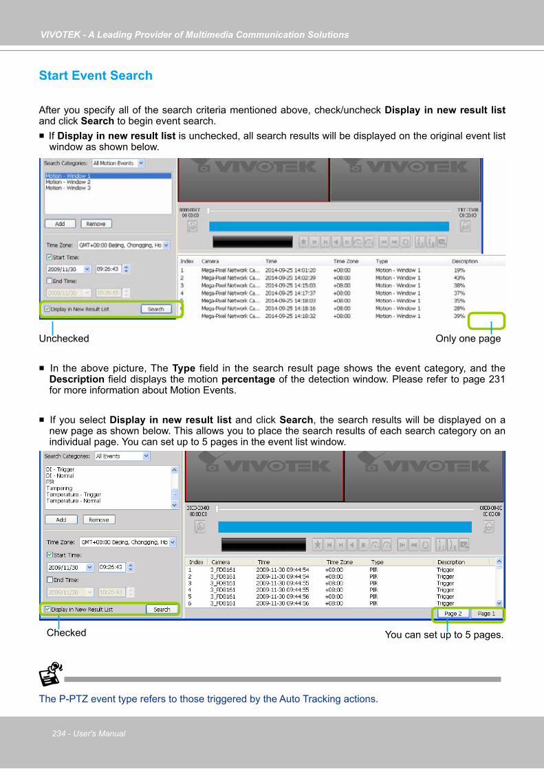
VIVOTEK - A Leading Provider of Multimedia Communication Solutions
234 - User's Manual
Start Event Search
After you specify all of the search criteria mentioned above, check/uncheck Display in new result list and click Search to begin event search. If Display in new result list is unchecked, all search results will be displayed on the original event list
window as shown below.
In the above picture, The Type field in the search result page shows the event category, and the Description field displays the motion percentage of the detection window. Please refer to page 231 for more information about Motion Events.
If you select Display in new result list and click Search, the search results will be displayed on a new page as shown below. This allows you to place the search results of each search category on an individual page. You can set up to 5 pages in the event list window.
Unchecked Only one page
Checked You can set up to 5 pages.
The P-PTZ event type refers to those triggered by the Auto Tracking actions.
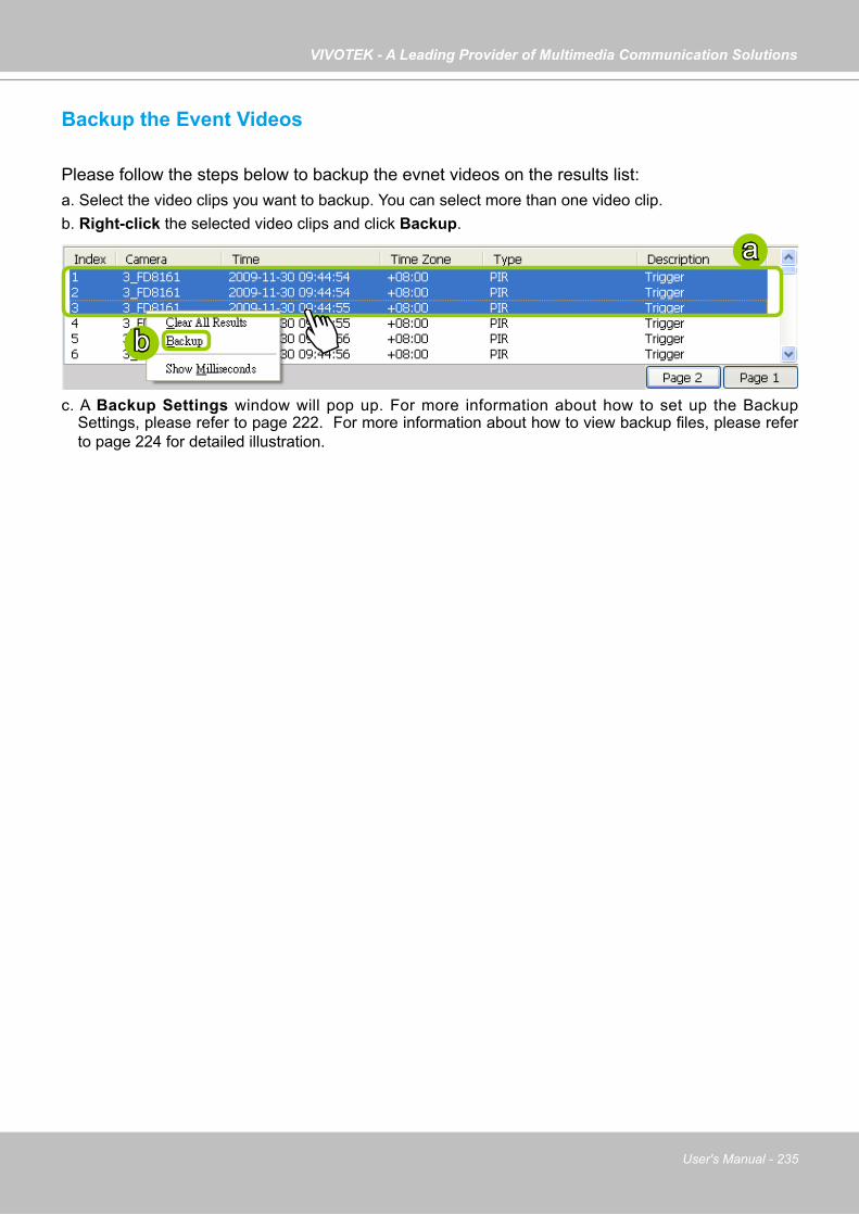
VIVOTEK - A Leading Provider of Multimedia Communication Solutions
User's Manual - 235
Backup the Event Videos
Please follow the steps below to backup the evnet videos on the results list:a. Select the video clips you want to backup. You can select more than one video clip.b. Right-click the selected video clips and click Backup.
c. A Backup Settings window will pop up. For more information about how to set up the Backup Settings, please refer to page 222. For more information about how to view backup files, please refer to page 224 for detailed illustration.
a
b
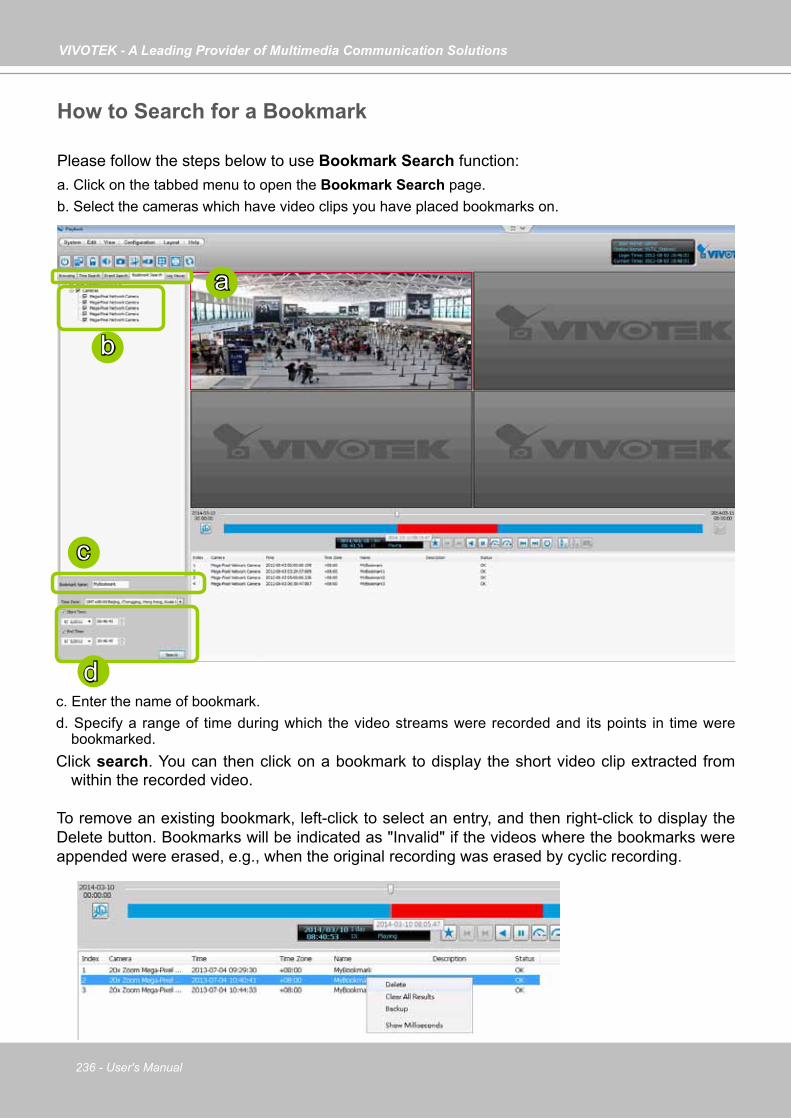
VIVOTEK - A Leading Provider of Multimedia Communication Solutions
236 - User's Manual
How to Search for a Bookmark
Please follow the steps below to use Bookmark Search function:a. Click on the tabbed menu to open the Bookmark Search page.b. Select the cameras which have video clips you have placed bookmarks on.
c. Enter the name of bookmark. d. Specify a range of time during which the video streams were recorded and its points in time were
bookmarked. Click search. You can then click on a bookmark to display the short video clip extracted from
within the recorded video.
To remove an existing bookmark, left-click to select an entry, and then right-click to display the Delete button. Bookmarks will be indicated as "Invalid" if the videos where the bookmarks were appended were erased, e.g., when the original recording was erased by cyclic recording.
a
c
d
b
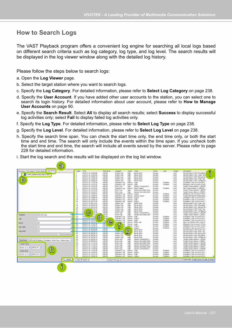
VIVOTEK - A Leading Provider of Multimedia Communication Solutions
User's Manual - 237
How to Search Logs
The VAST Playback program offers a convenient log engine for searching all local logs based on different search criteria such as log category, log type, and log level. The search results will be displayed in the log viewer window along with the detailed log history.
Please follow the steps below to search logs:a. Open the Log Viewer page.b. Select the target station where you want to search logs.c. Specify the Log Category. For detailed information, please refer to Select Log Category on page 238.d. Specify the User Account. If you have added other user accounts to the station, you can select one to
search its login history. For detailed information about user account, please refer to How to Manage User Accounts on page 90.
e. Specify the Search Result. Select All to display all search results; select Success to display successful log activities only; select Fail to display failed log activities only.
f. Specify the Log Type. For detailed information, please refer to Select Log Type on page 238. g. Specify the Log Level. For detailed information, please refer to Select Log Level on page 238. h. Specify the search time span. You can check the start time only, the end time only, or both the start
time and end time. The search will only include the events within the time span. If you uncheck both the start time and end time, the search will include all events saved by the server. Please refer to page 228 for detailed information.
i. Start the log search and the results will be displayed on the log list window.
a
b
c
h
ed
i
i
f g
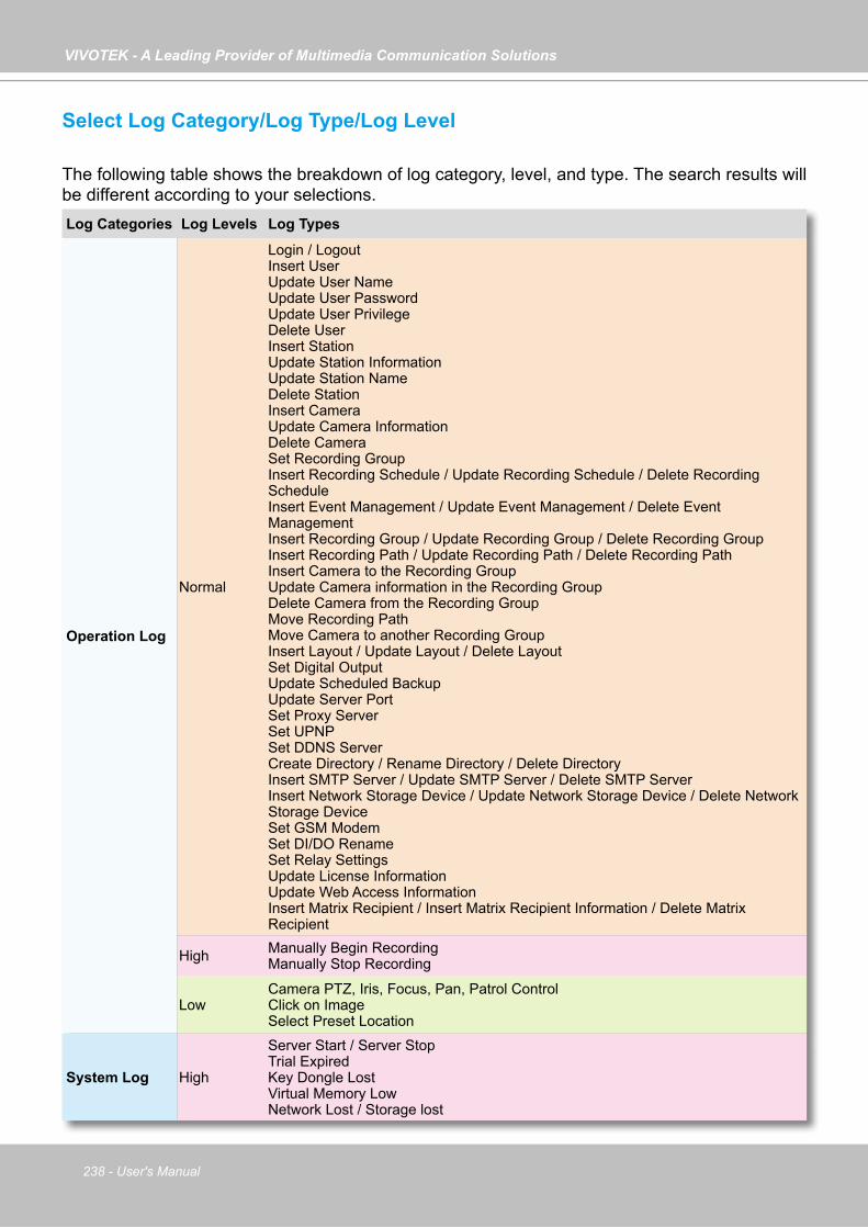
VIVOTEK - A Leading Provider of Multimedia Communication Solutions
238 - User's Manual
Select Log Category/Log Type/Log Level
The following table shows the breakdown of log category, level, and type. The search results will be different according to your selections.Log Categories Log Levels Log Types
Operation Log
Normal
Login / LogoutInsert UserUpdate User NameUpdate User PasswordUpdate User PrivilegeDelete UserInsert StationUpdate Station InformationUpdate Station NameDelete StationInsert CameraUpdate Camera InformationDelete CameraSet Recording GroupInsert Recording Schedule / Update Recording Schedule / Delete Recording ScheduleInsert Event Management / Update Event Management / Delete Event ManagementInsert Recording Group / Update Recording Group / Delete Recording GroupInsert Recording Path / Update Recording Path / Delete Recording PathInsert Camera to the Recording GroupUpdate Camera information in the Recording GroupDelete Camera from the Recording GroupMove Recording PathMove Camera to another Recording GroupInsert Layout / Update Layout / Delete LayoutSet Digital OutputUpdate Scheduled Backup Update Server Port Set Proxy ServerSet UPNPSet DDNS ServerCreate Directory / Rename Directory / Delete Directory Insert SMTP Server / Update SMTP Server / Delete SMTP ServerInsert Network Storage Device / Update Network Storage Device / Delete Network Storage DeviceSet GSM ModemSet DI/DO RenameSet Relay SettingsUpdate License InformationUpdate Web Access InformationInsert Matrix Recipient / Insert Matrix Recipient Information / Delete Matrix Recipient
High Manually Begin RecordingManually Stop Recording
LowCamera PTZ, Iris, Focus, Pan, Patrol ControlClick on ImageSelect Preset Location
System Log High
Server Start / Server StopTrial ExpiredKey Dongle LostVirtual Memory LowNetwork Lost / Storage lost
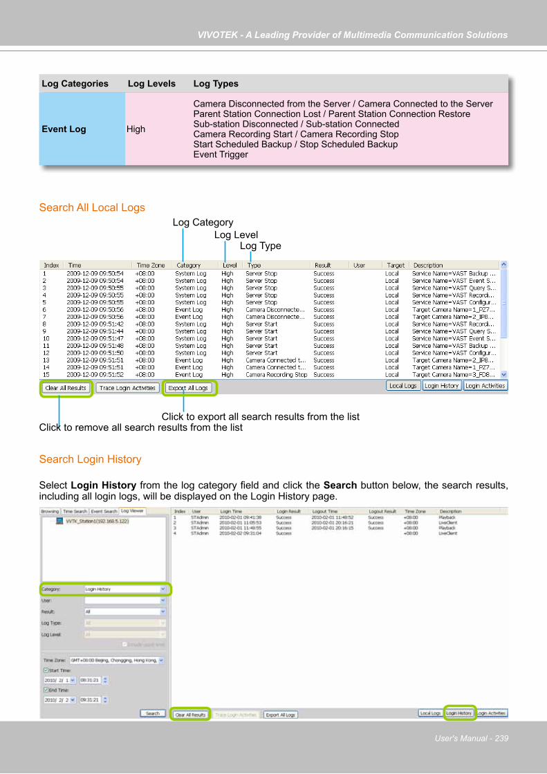
VIVOTEK - A Leading Provider of Multimedia Communication Solutions
User's Manual - 239
Search All Local Logs
Search Login History
Select Login History from the log category field and click the Search button below, the search results, including all login logs, will be displayed on the Login History page.
Log Categories Log Levels Log Types
Event Log High
Camera Disconnected from the Server / Camera Connected to the ServerParent Station Connection Lost / Parent Station Connection RestoreSub-station Disconnected / Sub-station ConnectedCamera Recording Start / Camera Recording Stop Start Scheduled Backup / Stop Scheduled Backup Event Trigger
Log LevelLog Category
Log Type
Click to remove all search results from the listClick to export all search results from the list
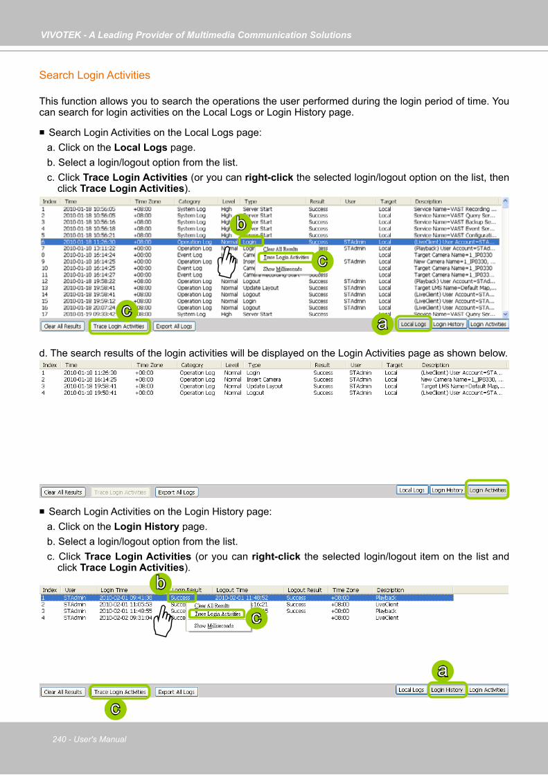
VIVOTEK - A Leading Provider of Multimedia Communication Solutions
240 - User's Manual
Search Login Activities
This function allows you to search the operations the user performed during the login period of time. You can search for login activities on the Local Logs or Login History page.
Search Login Activities on the Local Logs page:a. Click on the Local Logs page.b. Select a login/logout option from the list.c. Click Trace Login Activities (or you can right-click the selected login/logout option on the list, then
click Trace Login Activities).
d. The search results of the login activities will be displayed on the Login Activities page as shown below.
Search Login Activities on the Login History page:a. Click on the Login History page.b. Select a login/logout option from the list.c. Click Trace Login Activities (or you can right-click the selected login/logout item on the list and
click Trace Login Activities).
a
b
c
c
a
b
c
c

VIVOTEK - A Leading Provider of Multimedia Communication Solutions
User's Manual - 241
d. The search results of the login activities will be displayed on the Login Activities page as shown below.
When you select All in the Log Level field, the search results will include all log levels. If you select Low in the Log Level field and select Including above level as shown in the picture on the left below, the search results will include all levels of logs. But if you select Normal in the Log Level field and select Including above level as shown in the picture on the right below, the search results will only include Normal-level and High-level logs.
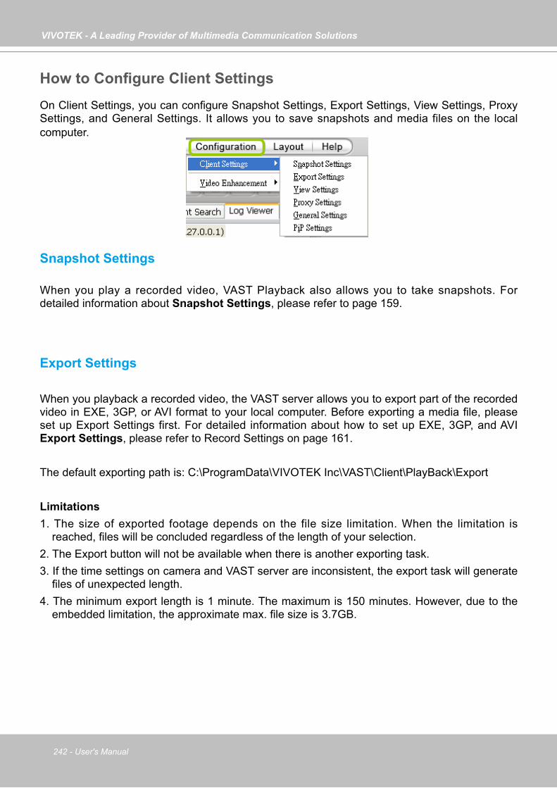
VIVOTEK - A Leading Provider of Multimedia Communication Solutions
242 - User's Manual
How to Configure Client SettingsOn Client Settings, you can configure Snapshot Settings, Export Settings, View Settings, Proxy Settings, and General Settings. It allows you to save snapshots and media files on the local computer.
Snapshot Settings
When you play a recorded video, VAST Playback also allows you to take snapshots. For detailed information about Snapshot Settings, please refer to page 159.
Export Settings
When you playback a recorded video, the VAST server allows you to export part of the recorded video in EXE, 3GP, or AVI format to your local computer. Before exporting a media file, please set up Export Settings first. For detailed information about how to set up EXE, 3GP, and AVI Export Settings, please refer to Record Settings on page 161.
The default exporting path is: C:\ProgramData\VIVOTEK Inc\VAST\Client\PlayBack\Export
Limitations 1. The size of exported footage depends on the file size limitation. When the limitation is
reached, files will be concluded regardless of the length of your selection.2. The Export button will not be available when there is another exporting task.3. If the time settings on camera and VAST server are inconsistent, the export task will generate
files of unexpected length. 4. The minimum export length is 1 minute. The maximum is 150 minutes. However, due to the
embedded limitation, the approximate max. file size is 3.7GB.
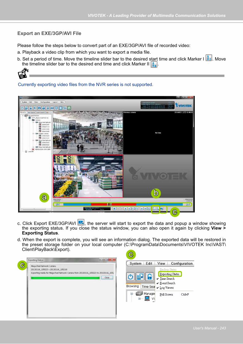
VIVOTEK - A Leading Provider of Multimedia Communication Solutions
User's Manual - 243
Export an EXE/3GP/AVI File
Please follow the steps below to convert part of an EXE/3GP/AVI file of recorded video:a. Playback a video clip from which you want to export a media file.b. Set a period of time. Move the timeline slider bar to the desired start time and click Marker I . Move
the timeline slider bar to the desired end time and click Marker II .
c. Click Export EXE/3GP/AVI , the server will start to export the data and popup a window showing the exporting status. If you close the status window, you can also open it again by clicking View > Exporting Status.
d. When the export is complete, you will see an information dialog. The exported data will be restored in the preset storage folder on your local computer (C:\ProgramData\Documents\VIVOTEK Inc\VAST\Client\PlayBack\Export).
a b
c
cc
Currently exporting video files from the NVR series is not supported.
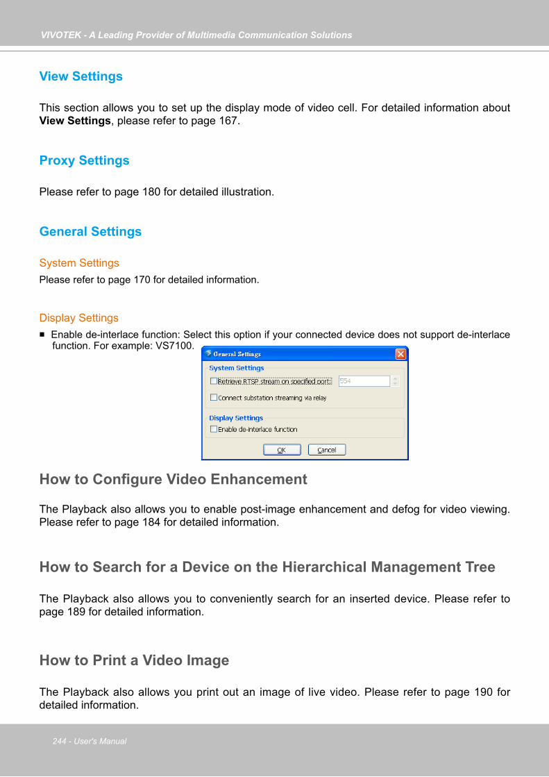
VIVOTEK - A Leading Provider of Multimedia Communication Solutions
244 - User's Manual
View Settings
This section allows you to set up the display mode of video cell. For detailed information about View Settings, please refer to page 167.
Proxy Settings
Please refer to page 180 for detailed illustration.
General Settings
System SettingsPlease refer to page 170 for detailed information.
Display Settings Enable de-interlace function: Select this option if your connected device does not support de-interlace
function. For example: VS7100.
How to Configure Video Enhancement
The Playback also allows you to enable post-image enhancement and defog for video viewing. Please refer to page 184 for detailed information.
How to Search for a Device on the Hierarchical Management Tree
The Playback also allows you to conveniently search for an inserted device. Please refer to page 189 for detailed information.
How to Print a Video Image
The Playback also allows you print out an image of live video. Please refer to page 190 for detailed information.
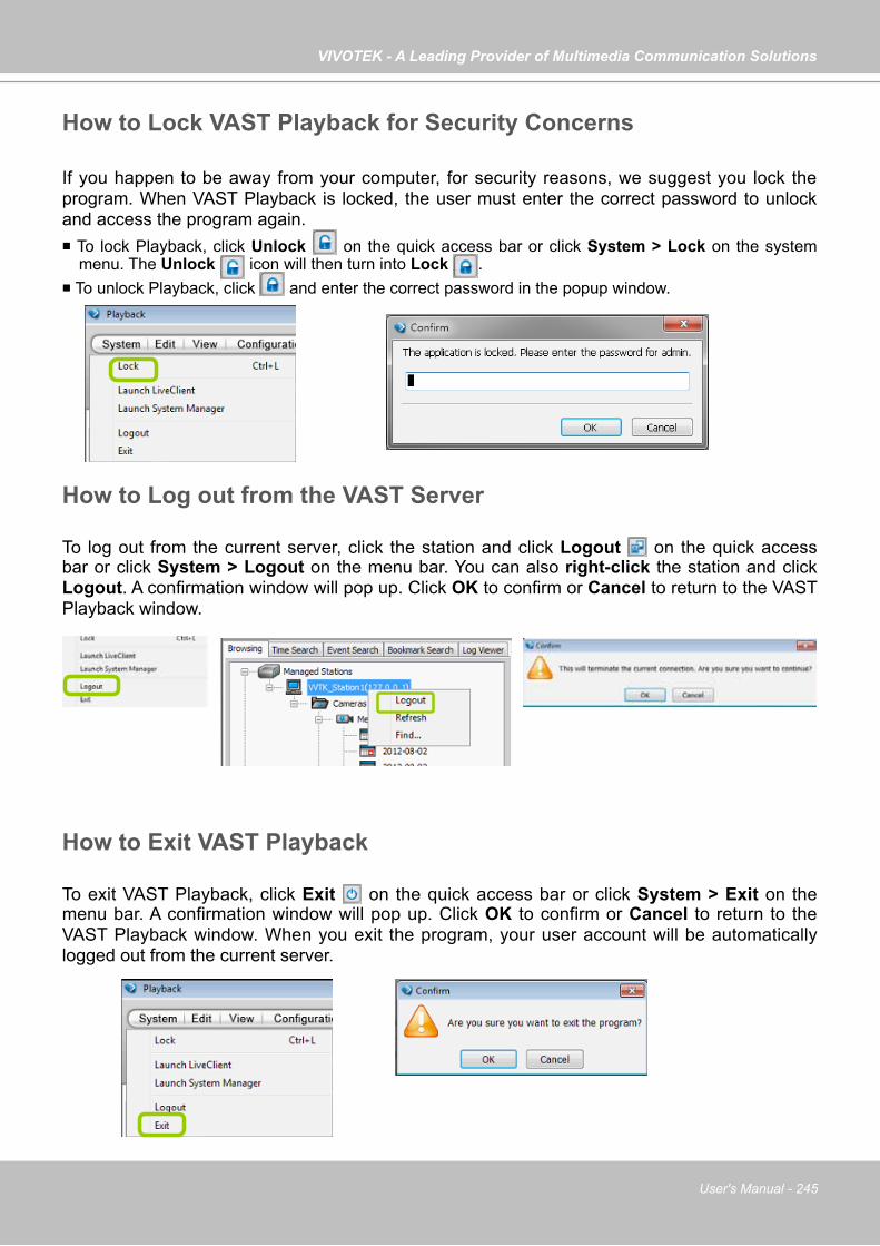
VIVOTEK - A Leading Provider of Multimedia Communication Solutions
User's Manual - 245
How to Lock VAST Playback for Security Concerns
If you happen to be away from your computer, for security reasons, we suggest you lock the program. When VAST Playback is locked, the user must enter the correct password to unlock and access the program again. To lock Playback, click Unlock on the quick access bar or click System > Lock on the system
menu. The Unlock icon will then turn into Lock . To unlock Playback, click and enter the correct password in the popup window.
How to Log out from the VAST Server
To log out from the current server, click the station and click Logout on the quick access bar or click System > Logout on the menu bar. You can also right-click the station and click Logout. A confirmation window will pop up. Click OK to confirm or Cancel to return to the VAST Playback window.
How to Exit VAST Playback
To exit VAST Playback, click Exit on the quick access bar or click System > Exit on the menu bar. A confirmation window will pop up. Click OK to confirm or Cancel to return to the VAST Playback window. When you exit the program, your user account will be automatically logged out from the current server.
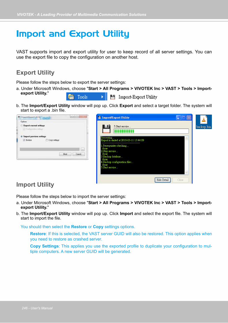
VIVOTEK - A Leading Provider of Multimedia Communication Solutions
246 - User's Manual
Import and Export Utility
VAST supports import and export utility for user to keep record of all server settings. You can use the export file to copy the configuration on another host.
Export UtilityPlease follow the steps below to export the server settings:a. Under Microsoft Windows, choose "Start > All Programs > VIVOTEK Inc > VAST > Tools > Import-
export Utility."
b. The Import/Export Utility window will pop up. Click Export and select a target folder. The system will start to export a .bin file.
Import Utility
Please follow the steps below to import the server settings:a. Under Microsoft Windows, choose "Start > All Programs > VIVOTEK Inc > VAST > Tools > Import-
export Utility."b. The Import/Export Utility window will pop up. Click Import and select the export file. The system will
start to import the file.
You should then select the Restore or Copy settings options. Restore: If this is selected, the VAST server GUID will also be restored. This option applies when
you need to restore as crashed server. Copy Settings: This applies you use the exported profile to duplicate your configuration to mul-
tiple computers. A new server GUID will be generated.

VIVOTEK - A Leading Provider of Multimedia Communication Solutions
User's Manual - 247
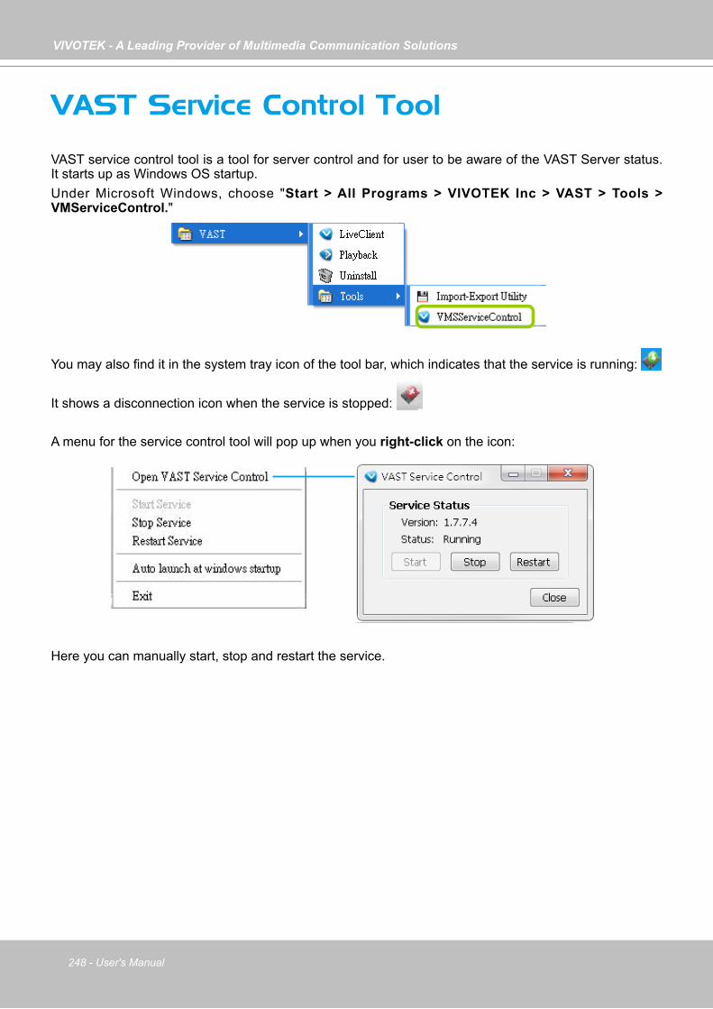
VIVOTEK - A Leading Provider of Multimedia Communication Solutions
248 - User's Manual
VAST Service Control Tool
VAST service control tool is a tool for server control and for user to be aware of the VAST Server status. It starts up as Windows OS startup.Under Microsoft Windows, choose "Start > All Programs > VIVOTEK Inc > VAST > Tools > VMServiceControl."
You may also find it in the system tray icon of the tool bar, which indicates that the service is running: It shows a disconnection icon when the service is stopped:
A menu for the service control tool will pop up when you right-click on the icon:
Here you can manually start, stop and restart the service.

VIVOTEK - A Leading Provider of Multimedia Communication Solutions
User's Manual - 249
Appendix A Panoramic PTZ (P-PTZ) Configuration
Enable Panoramic PTZ on VAST
The process of configuring two cameras (1 fisheye and 1 speed dome) into the Panoramic PTZ configuration takes place on a PC using the calibration tool. The Auto Tracking feature is configured using a web console with the fisheye camera. A Panoramic PTZ package should comprise two cameras running specific firmware for this application and a software CD containing all necessary utilities. For configuration details, please refer to the Panoramic PTZ Installation Guide.
Mapping table
360°All round view
ref. point 1
ref. point 2
ref. point 3
ref. point 4
ref. point 5
ref. point 6
ref. point 7
ref. point 8
ref. point 9
ref. point 10ref. point 11
ref. point 12
ref. point 1
ref. point 2
ref. point 3
ref. point 4
ref. point 5
ref. point 6
ref. point 7
ref. point 8
ref. point 9
ref. point 10ref. point 11
ref. point 12
Calibration tool
Pan/Tilt/Zoomcontrol
To exert Panoramic PTZ control on VAST: 1. Once these two cameras are configured into an interactive pair, insert these cameras into
your VAST configuration.2. Select a preferred layout using the Layout button. The 1P+2, 1P+6, and 1P+8 layouts
are specifically designed for the Panoramic PTZ configuration. 3. Taking the 1P+2 layout as an example, once they are listed on the device list, click and drag
the fisheye camera to the upper left and the bottom view cells. Place the speed dome in the upper right view cell.
Fisheye 1O Speed Dome
Fisheye 1P

VIVOTEK - A Leading Provider of Multimedia Communication Solutions
250 - User's Manual
4. Right-click on the fisheye's view cell to change its Display mode either into the 1O (Original) or the 1P (Panoramic) mode. Note that the Panoramic PTZ control does not take effects on the "R" (Regional) mode and the combinations of other display modes.
1
Click to move
2
Click and drag
2
Click and drag
Object of your interest
Object of your interest
5. There are two different ways to quickly exert Panoramic PTZ control. The pan, tilt, and zoom actions are made from the fisheye's 360° hemispheric overview:
5-1. Click on a spot on the fisheye's Original or Panoramic view where you detected a condition of your interest. The speed dome will aim its lens at the corresponding position to cover that field of view.
5-2. Click and drag a region of interest either on the Original or on the Panoramic view. The speed dome will move to that region and zoom in to fill the same proportion of view into its view cell. • On the Original view, click-and-drag creates a circular region of interest. • On the Panoramic view, a square region. • If you draw a small region, the speed dome will zoom in on the scene. The smaller the
region, the larger the zoom-in ratio. A large region makes the speed dome to zoom out.
The speed dome camera automatically performs optical zoom in/out to best fit the selected field of view until the maximum and minimum zoom ratio is reached.
Tips:
1. When drawing a region of interest, click and drag from the center of your interest over a diagonal line to the bottom right. It is not like drawing a diagonal line from corner to corner.
2. To swipe the Panoramic view left or right, press and hold down the Ctrl. key and the left mouse button.
Object of your interest

VIVOTEK - A Leading Provider of Multimedia Communication Solutions
User's Manual - 251
1. The fisheye and the speed dome are made into an interactive pair using the calibration tool. The VAST software provides the control interface only. If the cameras have not been properly configured, the Panoramic PTZ function will not take effect.
2. If the password of the speed dome camera has been changed, you will need to open a web console with the fisheye camera to change the coordinate password.
3. You may need to reset the fisheye camera if the speed dome camera is powered on after you started the VAST software.
4. The precision level of the interactive positions between the view cells of the fisheye and the speed dome is determined by the mapping table. Make sure you have inserted a sufficient number of reference points and make good association of these points using the calibration tool.
5. Currently the associated event trigger by Auto Tracking is not supported on VAST. The associated event triggering is configured through a web console with the fisheye camera:
5-1. You should then create an event setting using the manual triggers as triggering sources. 5-2. When Auto Tracking takes place, the pre-configured event settings on the speed dome camera
can take associated actions, e.g., taking a snapshot, recording to SD, or triggering the DO pins.
6. The Panoramic PTZ function is currently not available on the Matrix or web console mode in VAST. 7. If the interactive camera pairs (Panoramic PTZ cameras) are managed under VAST substations, then
all of the VAST instances, such as the primary VAST server, the substations, and the client side must be running the revision that supports P-PTZ.

VIVOTEK - A Leading Provider of Multimedia Communication Solutions
252 - User's Manual
Panoramic PTZ - Event Trigger
The P-PTZ-related event types include: "triggered" and "returned to normal" when Auto Tracking takes place. Below are the configurable options with the event configuration:1. When configuring a recording schedule, the Auto Tracking actions can be selected as one of the event
triggers. The configuration is found in Configuration > Station Settings > Recording Schedule Settings.
2. When Auto Tracking is enabled, its actions are considered as one of the system event types. In Configuration > Event Management, P-PTZ is configurable as a Trigger Type in Event Management > New Event > Trigger. This event trigger can be associated with different actions, such as Email, recording, moving to a preset location, GSM message, HTTP, Client notification, etc.

VIVOTEK - A Leading Provider of Multimedia Communication Solutions
User's Manual - 253
3. Events triggered by Auto Tracking are also recorded into system logs.
Auto Tracking can also function as a Device type in the Event Management configuration.
4. As the result, in Playback > Event Search panel, Auto Tracking (P-PTZ Trigger/Normal) is also a search condition.
Once triggered, the P-PTZ Trigger and P-PTZ Normal events will create two short videos for a length of 30 seconds.
Note that the P-PTZ event is not triggered by Panoramic PTZ control on the view cells, it is triggered by Auto Tracking. Auto Tracking takes place when a moving object enters the pre-configured region of interest. Please refer to the Panoramic PTZ Installation Guide.
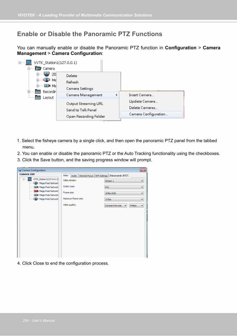
VIVOTEK - A Leading Provider of Multimedia Communication Solutions
254 - User's Manual
Enable or Disable the Panoramic PTZ Functions
You can manually enable or disable the Panoramic PTZ function in Configuration > Camera Management > Camera Configuration:
1. Select the fisheye camera by a single click, and then open the panoramic PTZ panel from the tabbed menu.
2. You can enable or disable the panoramic PTZ or the Auto Tracking functionality using the checkboxes.3. Click the Save button, and the saving progress window will prompt.
4. Click Close to end the configuration process.
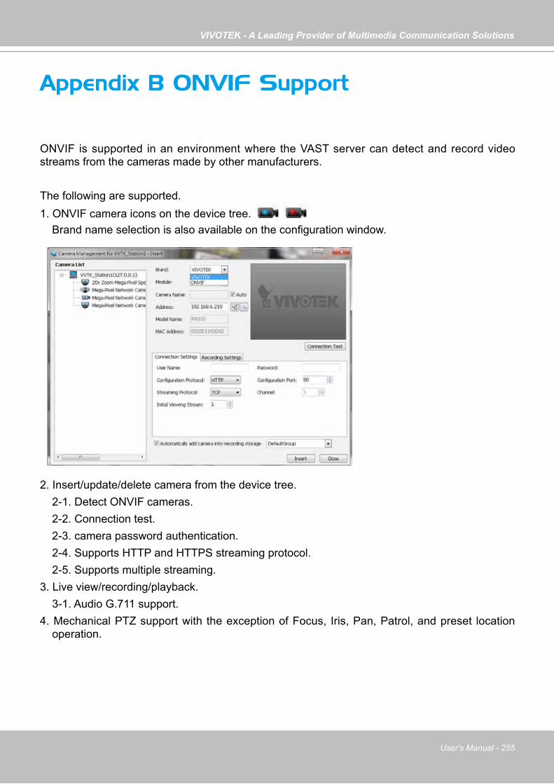
VIVOTEK - A Leading Provider of Multimedia Communication Solutions
User's Manual - 255
Appendix B ONVIF Support
ONVIF is supported in an environment where the VAST server can detect and record video streams from the cameras made by other manufacturers.
The following are supported. 1. ONVIF camera icons on the device tree. Brand name selection is also available on the configuration window.
2. Insert/update/delete camera from the device tree. 2-1. Detect ONVIF cameras. 2-2. Connection test. 2-3. camera password authentication. 2-4. Supports HTTP and HTTPS streaming protocol. 2-5. Supports multiple streaming.3. Live view/recording/playback. 3-1. Audio G.711 support.4. Mechanical PTZ support with the exception of Focus, Iris, Pan, Patrol, and preset location
operation.
VIVOTEK - A Leading Provider of Multimedia Communication Solutions
256 - User's Manual
Limitations:
The following limitations apply to ONVIF cameras made by other manufacturers. Some features may be implemented in later releases of software. 1. Users should ensure that your other brand cameras support ONVIF. 2. The connection statuses of the other brand cameras will not be displayed on the device tree.3. For mechanical PTZ cameras, the Focus, Iris, Pan, Patrol, and preset locations functions will
not be supported. The associated buttons and control elements on the UI screen will not be disabled.
4. Does not support the Batch Insert Camera function. 5. Does not support Camera Configuration. 6. Does not support Active Adaptive Stream (AAS) function. 7. Does not support Event related functions, including event recording, event management,
instant playback, event search, etc. 8. Does not support camera DI/DO. 9. Does not support Two Way Audio.10. Does not support Auto Stream Size.11. The ONVIF user authentication (account and password) may not comply with those
configured via a web console. 12. The number of multiple profiles can vary. 13. The number of accessible profile can vary. Some might have only one profile to be
connected.14. Does not support Click on Image.
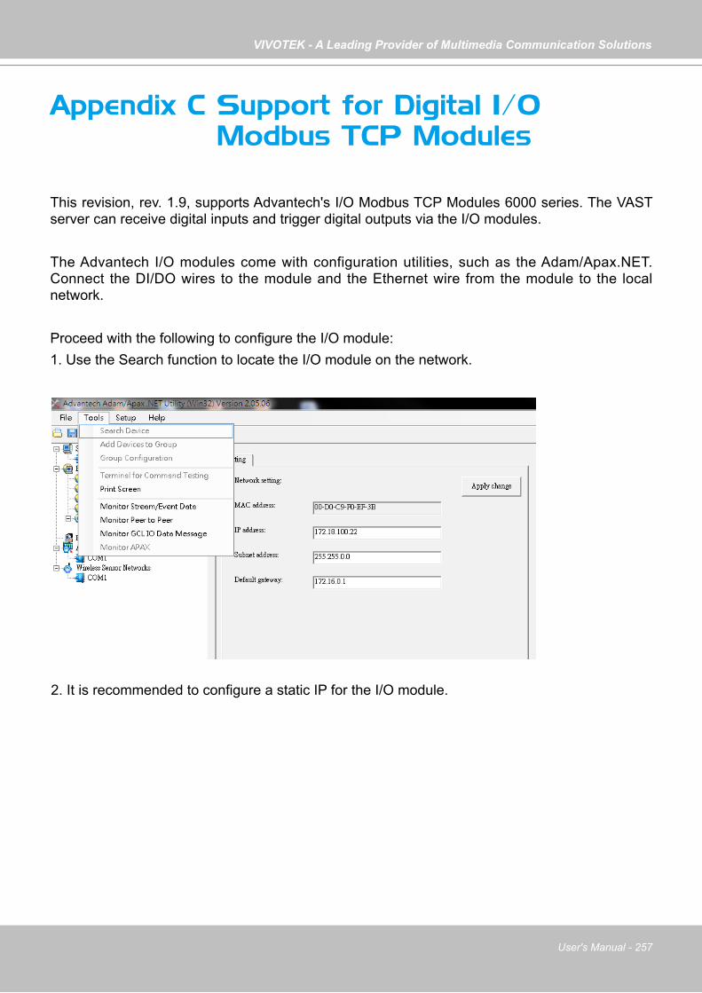
VIVOTEK - A Leading Provider of Multimedia Communication Solutions
User's Manual - 257
Appendix C Support for Digital I/O Modbus TCP Modules
This revision, rev. 1.9, supports Advantech's I/O Modbus TCP Modules 6000 series. The VAST server can receive digital inputs and trigger digital outputs via the I/O modules.
The Advantech I/O modules come with configuration utilities, such as the Adam/Apax.NET. Connect the DI/DO wires to the module and the Ethernet wire from the module to the local network.
Proceed with the following to configure the I/O module:1. Use the Search function to locate the I/O module on the network.
2. It is recommended to configure a static IP for the I/O module.
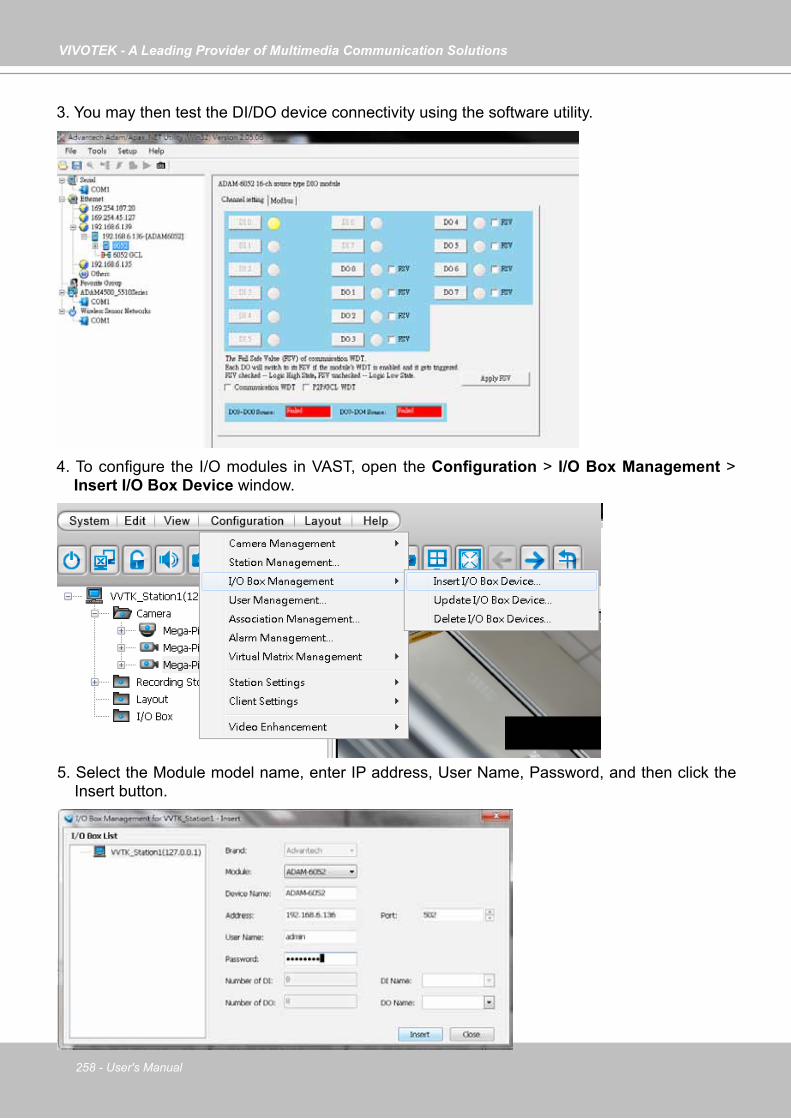
VIVOTEK - A Leading Provider of Multimedia Communication Solutions
258 - User's Manual
3. You may then test the DI/DO device connectivity using the software utility.
4. To configure the I/O modules in VAST, open the Configuration > I/O Box Management > Insert I/O Box Device window.
5. Select the Module model name, enter IP address, User Name, Password, and then click the Insert button.
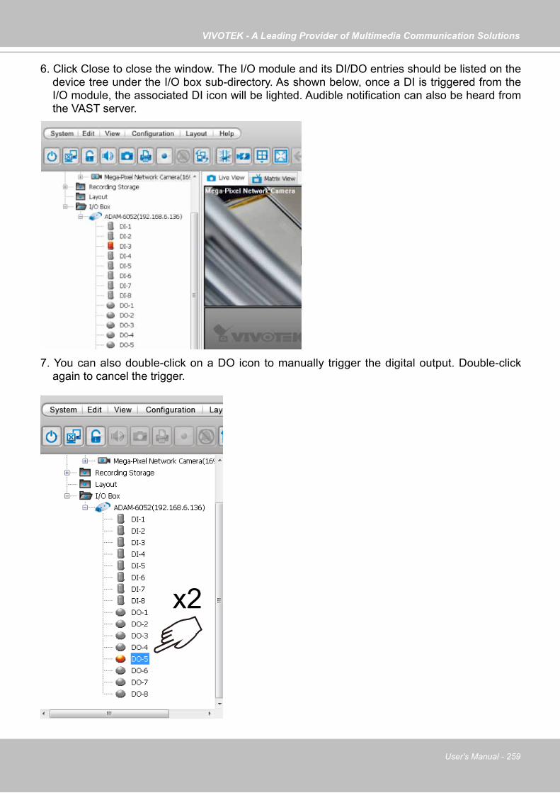
VIVOTEK - A Leading Provider of Multimedia Communication Solutions
User's Manual - 259
6. Click Close to close the window. The I/O module and its DI/DO entries should be listed on the device tree under the I/O box sub-directory. As shown below, once a DI is triggered from the I/O module, the associated DI icon will be lighted. Audible notification can also be heard from the VAST server.
x2
7. You can also double-click on a DO icon to manually trigger the digital output. Double-click again to cancel the trigger.
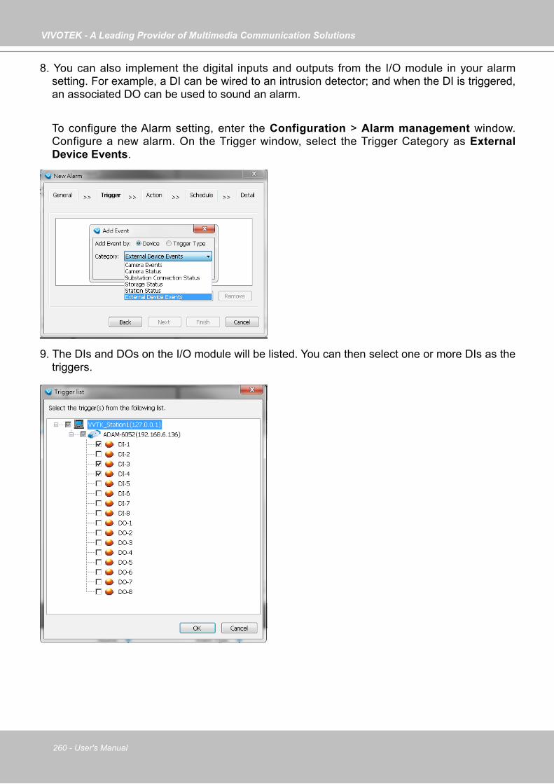
VIVOTEK - A Leading Provider of Multimedia Communication Solutions
260 - User's Manual
8. You can also implement the digital inputs and outputs from the I/O module in your alarm setting. For example, a DI can be wired to an intrusion detector; and when the DI is triggered, an associated DO can be used to sound an alarm.
To configure the Alarm setting, enter the Configuration > Alarm management window. Configure a new alarm. On the Trigger window, select the Trigger Category as External Device Events.
9. The DIs and DOs on the I/O module will be listed. You can then select one or more DIs as the triggers.
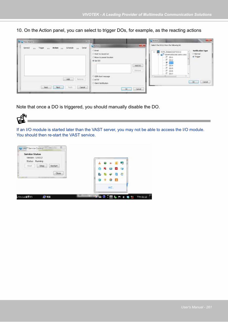
VIVOTEK - A Leading Provider of Multimedia Communication Solutions
User's Manual - 261
10. On the Action panel, you can select to trigger DOs, for example, as the reacting actions
Note that once a DO is triggered, you should manually disable the DO.
If an I/O module is started later than the VAST server, you may not be able to access the I/O module. You should then re-start the VAST service.
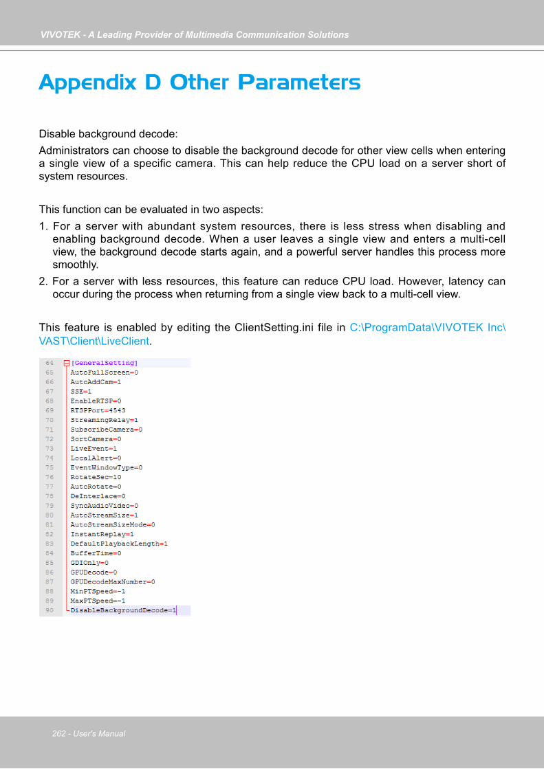
VIVOTEK - A Leading Provider of Multimedia Communication Solutions
262 - User's Manual
Appendix D Other Parameters
Disable background decode: Administrators can choose to disable the background decode for other view cells when entering a single view of a specific camera. This can help reduce the CPU load on a server short of system resources.
This function can be evaluated in two aspects:1. For a server with abundant system resources, there is less stress when disabling and
enabling background decode. When a user leaves a single view and enters a multi-cell view, the background decode starts again, and a powerful server handles this process more smoothly.
2. For a server with less resources, this feature can reduce CPU load. However, latency can occur during the process when returning from a single view back to a multi-cell view.
This feature is enabled by editing the ClientSetting.ini file in C:\ProgramData\VIVOTEK Inc\VAST\Client\LiveClient.