Embed Size (px)
Citation preview
VIVAH IP1776ENrev. 2012-02-20
Installation manual for control panel for automations with one or two 24 V= motor. EN
DITEC S.p.A.Via Mons. Banfi, 3 - 21042 Caronno Pertusella (VA) - ITALYTel. +39 02 963911 - Fax +39 02 9650314 www.ditec.it - [email protected]
- +O
utpu
t 24
V=
/ max
0.5
A
Aut
omat
ic c
losi
ng
Gat
e op
en in
dica
tor l
ight
Flas
hing
ligh
tE
lect
ric lo
ck
Clo
sing
Ste
p-by
-ste
pS
afet
y st
opS
afet
y st
opS
afet
y re
-ope
ning
Par
tial o
peni
ngS
afet
y te
st
Sto
p
Ope
ning
Power supply
L N 15 14 13 0 0 1 1 2 3 4 5 6 7 8 9 20 4136 35 34 33 32 31
AU
X1
AU
X2
IN
SAPOWERALARM
BAT
F1
F2
Transformer
VM M1 M2 R1
TC TR RP
COM
JR14
NIO
FSFC
S1S2S3S4
SO EO OM
ON
OFF 1 2 3 4 5 6
BATKH
24 V~TRF
24V=
Motor 2
24V=
Motor 1
GOL4
2IP1776EN 2012-02-20
INDEXSubject Page
1. General safety precautions 32. EC declaration of conformity 43. Technical data 4
3.1 Applications 44. Connection of power supply 45. Commands 5
5.1 SOFA1-SOFA2 self-controlled safety edge 66. Outputs and accessories 77. Adjustments 8
7.1 Selection of automation type 108. Connection of motors 119. Start-up 1210. Troubleshooting 1311. Example application for one-motor automations 1412. Example application for two-motors swing gates 1513. Example application for up-and-over doors with in-parallel motors 16
CAPTION
i
STOP
This symbol indicates instructions or notes regarding safety issues which require particular attention.
This symbol indicates informations which are useful for correct product function.
This symbol indicates options and parameters which are only available with the indicated item.
This symbol indicates options and parameters which are not available with the indicated item.
This symbol indicates instructions or notes intended for technical and expert personnel.
This symbol indicates operations not to be effected for not compromise the correct operation of the automation.
All right reservedAll data and speci cations have been drawn up and chec ed with the greatest care. The manufacturer cannot however ta e any responsibility for eventual errors, ommisions or incomplete data due to technical or illustrative purposes.
3 IP1776EN 2012-02-20
1. GENERAL SAFETY PRECAUTIONSThis installation manual is intended for professionally competent personnel only.The installation, the power connections and the settings must be completed in conformity with Good
or ing Methods and with the regulations in force.Before installing the product, carefully read the instructions. Bad installation could be ha ardous. The pac aging materials (plastic, polystyrene, etc.) should not be discarded in the environment or left within reach of children, as these are a potential source of hazard.Before beginning the installation chec that the product is in perfect condition.
o not install the product in explosive areas and atmospheres the presence of ammable gas or fumes re-presents a serious threat to safety.The safety devices (photocells, sensitive edges, emergency stop, etc.) must be installed ta ing into account the provisions and the directives in force, Good or ing Methods, the installation area, the functional logic of the system and the forces developed by the automation.
Before ma ing power connections, chec that the rating corresponds to that of the mains supply. A mul-tipolar disconnection switch with a contact opening gap of at least 3 mm must be included in the mains
supply. Chec that upstream of the electrical installation an adequate residual current circuit brea er and an overcurrent cut out are tted.When requested, connect the automation to an effective earthing system carried out as indicated by current safety regulations.During installation, maintenance and repair operations, cut off the power supply before opening the cover to access the electrical parts.
To handle electronic parts, wear earthed antistatic conductive bracelets. The manufacturer of the moto-risation declines all responsibility in the event of components which are not compatible with the safe and
correct operation of the product.For repairs or replacements of products only original spare parts must be used.
4IP1776EN 2012-02-20
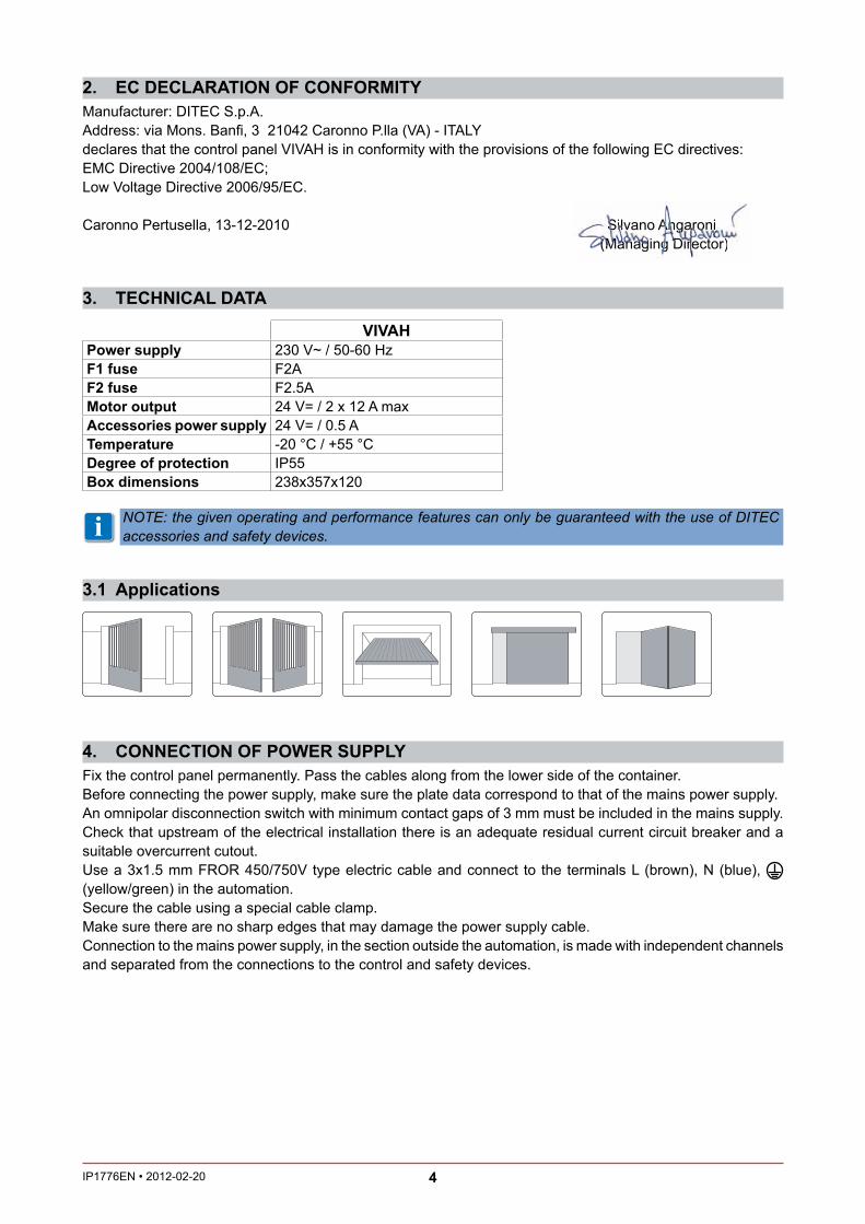
3.1 Applications
3. TECHNICAL DATA
i NOTE: the given operating and performance features can only be guaranteed with the use of DITEC accessories and safety devices.
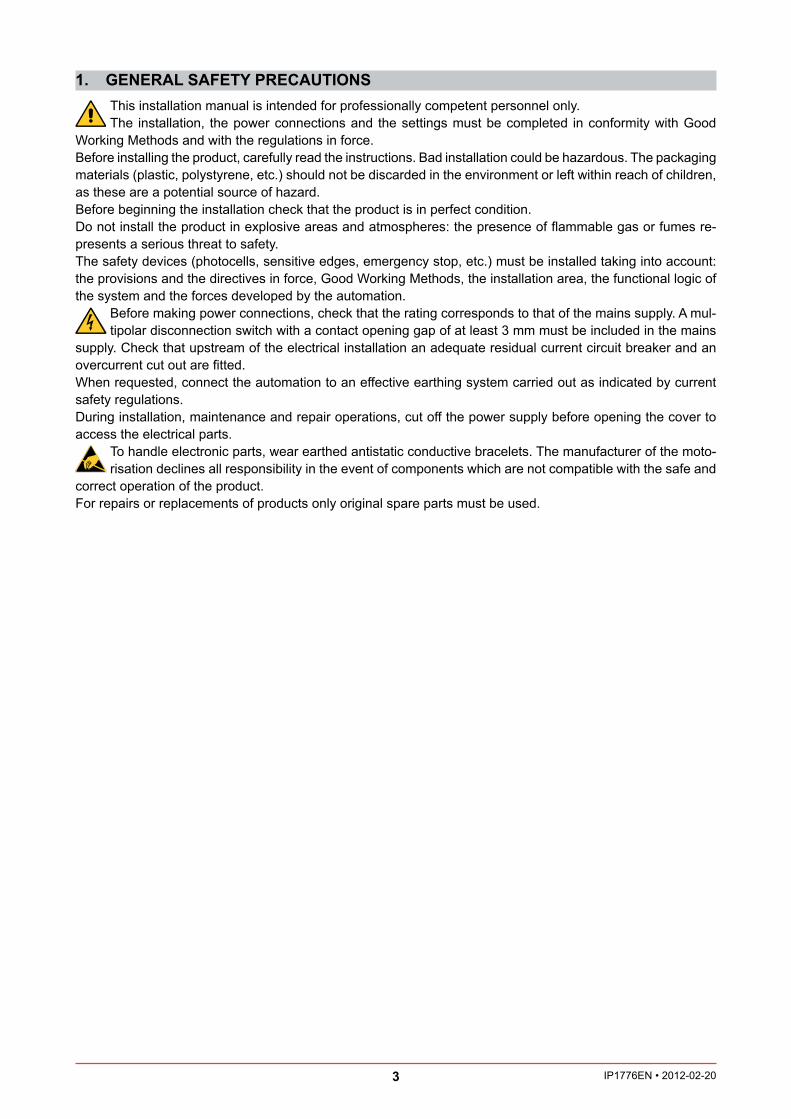
4. CONNECTION OF POWER SUPPLYFix the control panel permanently. Pass the cables along from the lower side of the container.Before connecting the power supply, ma e sure the plate data correspond to that of the mains power supply.An omnipolar disconnection switch with minimum contact gaps of 3 mm must be included in the mains supply. Chec that upstream of the electrical installation there is an adequate residual current circuit brea er and a suitable overcurrent cutout.Use a 3x1.5 mm FROR 450/750V type electric cable and connect to the terminals L (brown), N (blue), (yellow/green) in the automation.Secure the cable using a special cable clamp.Ma e sure there are no sharp edges that may damage the power supply cable.Connection to the mains power supply, in the section outside the automation, is made with independent channels and separated from the connections to the control and safety devices.
2. EC DECLARATION OF CONFORMITYManufacturer: DITEC S.p.A. Address: via Mons. Ban , 3 21042 Caronno P.lla (VA) - ITALYdeclares that the control panel VIVAH is in conformity with the provisions of the following EC directives: EMC Directive 2004/108/EC;Low Voltage Directive 2006/95/EC.
Caronno Pertusella, 13-12-2010 Silvano Angaroni (Managing Director)
VIVAHPower supply 230 V~ / 50-60 HzF1 fuse F2AF2 fuse F2.5AMotor output 24 V= / 2 x 12 A maxAccessories power supply 24 V= / 0.5 ATemperature -20 °C / +55 °CDegree of protection IP55Box dimensions 238x357x120
SSiSSSiSSSSSSSSSSSSSSSSSSSSSSSSSSiSSiiSSSiiSSSiiSSSSiiSSSSSSSSiiSSSilvllllllllvllvlvlvllvano AnAnAAAnAAAAAnAnAAnnAAnnnnAnnnnnnAnAnAAnnnnnAAAnnnnAAnnnAAnnnAnnnnnnAAAAnnnAAnnnnAAAnnnnnAnnnAnnnnngagaaaagagagaaagagagagagaaggggaaaaggggaaaaggggggggggggggggg roororrorororrrorrrrorrorrooorrrrrroooorrrrrrooooooorrrrrooooooooninnnnnnninnnnnn (((M((((MMMMMMMM(((M(M((M(MMMMMMMMM((((M((MMMM(MMMMMM((((MMMMMMMMMMMM(((MMMMMMM(M(MM((MMMMMMM(MMMMMMMMMMMM(MMMMM(MMMMMMMMMaananaananananaaaaaaaaaannnnnnnnnaaaaaaannnannnaaaaaanannnanaaaaaannaaaaaa aagaggggaaaaaaaagggggggaagaaggggggggggaaaaggggggggggggggggggggggggggggggggggggggging gggggggggggggggggggggggggggggggggggggggggggggggggggggggggggggggggggggggg DDiDDDiiDiiDDDiiiiDDDDiDiiDDDDiDDDDDDDDDD rerrererrrerrrerrrerrerrrrerrrrrrerrrerrecttttttttttttoroo )))))

5 IP1776EN 2012-02-20
5. COMMANDSCommand Function Description
1 2 N.O. AUTOMATICCLOSING
The permanent closing of the contact enables automatic clos-ing.
1 3 N.O. OPENING The closing of the contact activates the opening operation.1 4 N.O. CLOSING The closing of the contact activates the closing operation.1 5 N.O. STEP-BY-STEP The closing of the contact activates opening or closing operations
in the following sequence: open-stop-close-open. NOTE: if automatic closing is enabled, the stop is not permanent but lasts for a duration set by TC.
1 6 N.C. OPENINGSAFETY
The opening of the safety contact stops the opening operation in progress and prevents future opening operations.
1 7 N.C. CLOSINGSAFETY
The opening of the safety contact stops the closing operation in progress and prevents future closing operations.
1 6 7
N.C. SAFETY STOP All operations are stopped and/or bloc ed when the safety con-tact is opened. NOTE: it does not carry out the disengagement operation. WARNING: use with photocells only.
1 8 N.C. REVERSESAFETY CONTACT
The opening of the safety contact triggers a reversal of motion (re-opening) during closing. With SO=ON with the automation stopped, the opening of the contact prevents any operation.With SO=OFF with the automation stopped, the opening of the contact only prevents the closing operation.
1 9 N.C. STOP The opening of the safety contact stops the current operation. EMERGENCY STOP
Connect the opening and closing commands to terminal 9 instead of terminal 1 (9-3, 9-4, 9-20).
1 9 N.O. HOLD-TO-RUNFUNCTION
The opening of the 1-9 contact enables the hold-to-run function:- hold-to-run opening 1-3;- hold-to-run closing 1-4.NOTE: any safety device, automatic closing and plug-in card inserted in AUX1 or AUX2 is disabled.
1 20 N.O. PARTIAL OPENING The closing of the contact activates a partial opening operation of motor 1 (M1) of the duration set with the RP trimmer.Once the automation stops, the partial opening control per-forms the opposite operation to the one performed before stop.NOTE: if automatic closing is enabled, the stop is not permanent but lasts for a duration set by TC.
WARNING: make a jumper for all the N.C. contacts if not in use. The terminals with the same number are equal.

6IP1776EN 2012-02-20
5.1 SOFA1-SOFA2 self-controlled safety edgeCommand Function Description
SOFA1-SOFA2
0 411
SAFETY TEST Place the SOFA1-SOFA2 device into its housing for plug-in cards AUX1 or AUX2.With JR14=OFF, connecting terminal 41 enables a safety edge test cycle before every operation. If the test fails the SA led ashes and the test is repeated.
1 6 N.C. OPENINGSAFETY
Connect the output contact of device to terminals 1-6 on the con-trol panel (in series with the photocell output contact, if installed).ATTENTION: make a jumper among 41-6 contacts if not used.
1 7 N.C. CLOSINGSAFETY
Connect the output contact of device to terminals 1-7 on the con-trol panel (in series with the photocell output contact, if installed).ATTENTION: make a jumper among 41-7 contacts if not used.
1 8 N.C. REVERSESAFETY CONTACT
Connect the output contact of device to terminals 1-8 on the con-trol panel (in series with the photocell output contact, if installed).ATTENTION: make a jumper among 41-8 contacts if not used.

7 IP1776EN 2012-02-20
6. OUTPUTS AND ACCESSORIESOutput Value - Accessories Description
0 1+-
24 V= / 0.5 AAccessories power supply. Power supply output for external ac-cessories, including automation status lamp.Electronically protected output.
1 13 24 V= / 3 W
Automation status lamp (proportional).The light switches off when the automation is closed; the light switches on when the automation is open; the light ashes with a variable frequency while the automation is operating.
0 14LAMPH
24 V= / 25 W
Flashing light. With DIP6=OFF activated during opening and closing operations.Output protected by F2 fuse.
0 14 24 V= / 25 W
Courtesy light. With DIP6=ON an external courtesy light that turns on for 180 s with every opening (total or partial), step-by-step and closing command can be connected.Output protected by F2 fuse.
0 15 24 V= / 300 mA Electric block. It is activated when the automation is closed.Output protected by F2 fuse.
0 15 12 V~ / 15 W Electric lock. Connect the supplied 8.2 / 5W resistance in series.Output protected by F2 fuse.
AUX1AUX2
The control panel has two housings for plug-in cards such as a ra-dio receiver type, magnetic loops, etc.Plug-in card operating is selected using DIP1.WARNING: the plug-in cards must be inserted and removed with the power supply disconnected.
COM DO NOT USE
BAT BATKH2 x 12 V / 2 Ah
Battery operating. The batteries are ept charged when the power supply is on. If the power supply is off, the control panel is powered by the batteries until power is re-established or until the battery voltage drops below the safety threshold. If this occurs, the control panel turns off.WARNING: the batteries must always be connected to the control panel for charging. eriodically check the ef ciency of the batteries.NOTE: the operating temperature of the rechargeable batteries is approximately +5°C/+40°C.

8IP1776EN 2012-02-20
7. ADJUSTMENTSDescription OFF ON
DIP1 Plug-in cards operation.NOTE: it sets the operating mode of the plug-in cards connected on AUX1 and AUX2.
Step-by-step. Opening.
DIP2 Restore automatic closing time. 50% 100%DIP3 Automation status at power on.
Indicates how the control panel considers automation when powered up.
Open. Closed.NOTE: if the automatic clo-sing function is not used, preferably set DIP3=ON.
DIP4 Electric lock release. Disabled. Enabled. NOTE: when the electric lock is installed, set DIP4=ON.
Electric block operation.NOTE: only with EO=OFF.
Powered for the entire opening and closing opera-tion.
Powered only with the au-tomation closed.
DIP5 3 seconds pre ashing. Disabled during opening.Enabled only with automatic closing with TC>3 s.
Enabled for both opening and closing.
DIP6 Output 0-14 operation. Flashing light. Courtesy light.
Description OFF ON FC Limit switch mode selection. Stop limit switch. Slow down limit switch.SO Reversal safety switch function. With the automation bloc ed,
if the contact 1-8 is open, it is possible to activate the opening operation.
With the automation bloc ed, if the contact 1-8 is open, any operation is impossible.
EO Electric lock operation. Powered for 2.5 s at the beginning of the opening operation.
Powered for 1.2 s at the beginning of the opening operation.
OM Automation type. Automation with 1 motor or with 2 motors in parallel.
Automation with 2 indepen-dent motors.
FS FUTURE USE / /NIO Electronic antifreeze system.
Maintains motor function even at low am-bient temperatures.
Enabled. Disabled.
JR14 Safety test terminal 41. Enabled. Disabled.
DO
KE

9 IP1776EN 2012-02-20
Trimmer DescriptionTC
0 s Disabled
120 s
Setting automatic closing time. From 0 to 120 s.With DIP2=OFF, once a safety switch has been activated, the counter starts as soon as the safety switch is released (for example after passing through the photocells), and lasts for a period of time set with trimmer TC (50%).With DIP2=ON, the counter starts when automation is opened and lasts for the entire duration set with trimmer TC (100%).NOTE: after the activation of the stop command, once contact 1-9 has closed again, automatic closing is only enabled after a total, partial or step-by-step opening com-mand.
TR
0 s
3 s
30 s
20 s
10 s
Setting motor 1 (M1) closing delay time. From 0 to 30 s.When closing, motor 1 (M1) arrives after a delay set with trimmer TR relative to motor 2 (M2). When opening, motor 2 (M2) starts after a delay of 3 s relative to motor 1 (M1).With TR=MIN the door wings start simultaneously.NOTE: setting TR=MIN with non-overlapping door wings and setting TR>3 s with overlapping door wings is recommended.
RP
10% 100%
Motor 1 (M1) partial opening adjustment.Adjust the percentage of partial opening of motor 1 (M1) from 10% to 100% of the total operation.
VM
min max
Operation speed adjustment.Adjusts the automation operation speed.The closing speed is the same as the opening speed.
M1-M2
5 s 30 s
Motor 1 (M1) operating time adjustment. From 5 s to 30 s.Motor 2 (M2) operating time adjustment. From 5 s to 30 s.(or from 5 s to 45 s depending on the settings in paragraph 6.4).The opening/closing operation is shown in chapters 11, 12 and 13: the operation con-sists of a part with the speed set with trimmer VM, the duration set with trimmer M1/M2 and deceleration to a xed speed when both opening and closing.When opening, this deceleration lasts a maximum of 10 s and when closing, it lasts until the mechanical stop or a stop limit switch is reached (with FC=OFF).
R1
min max
Force adjustment. The control panel is tted with a safety device which, when it detects an obstacle:- during opening, stops movement with a disengagement operation;- during closing, before deceleration, inverts movement;- during closing, during deceleration with FC=ON stops movement and with FC=OFF
inverts movement.
10IP1776EN 2012-02-20
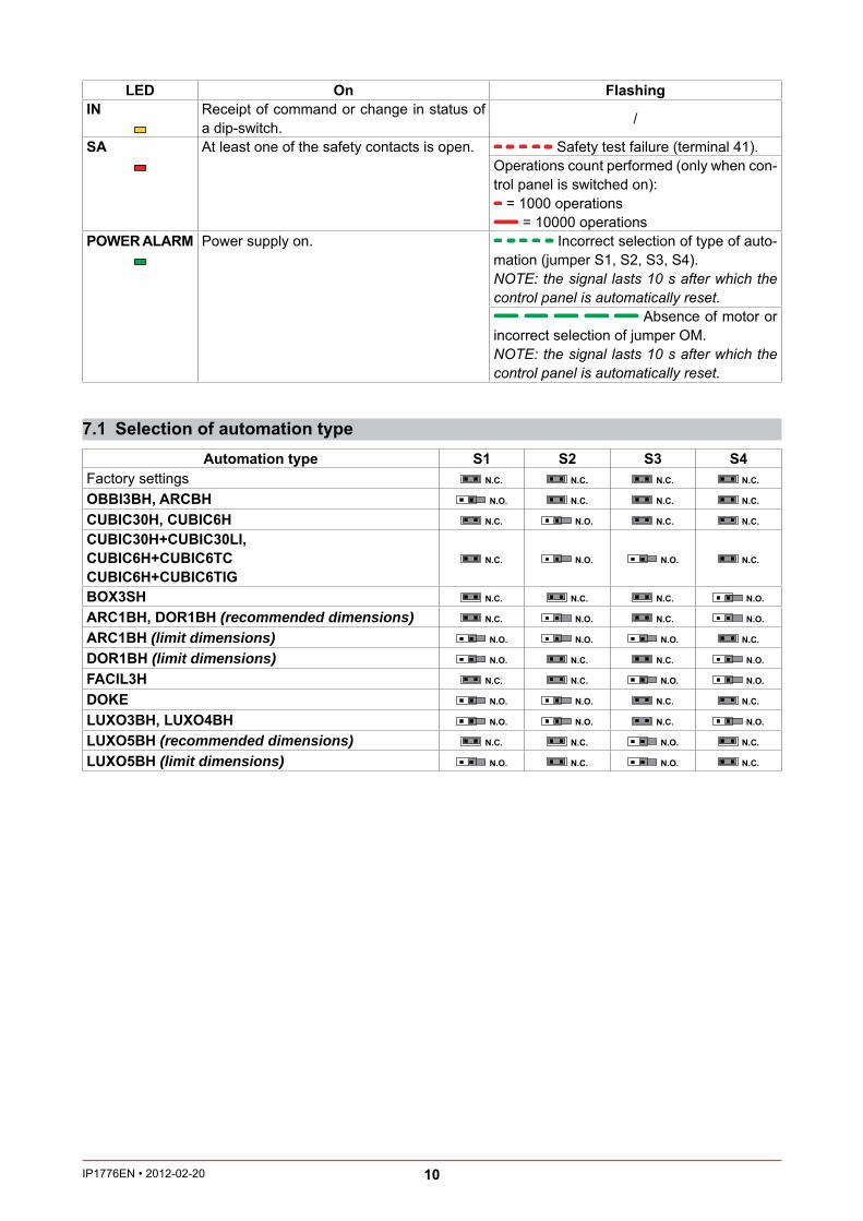
LED On FlashingIN Receipt of command or change in status of
a dip-switch. /
SA At least one of the safety contacts is open. Safety test failure (terminal 41).Operations count performed (only when con-trol panel is switched on):
= 1000 operations = 10000 operations
POWER ALARM Power supply on. Incorrect selection of type of auto-mation (jumper S1, S2, S3, S4).NOTE: the signal lasts 10 s after which the control panel is automatically reset.
Absence of motor or incorrect selection of jumper OM.NOTE: the signal lasts 10 s after which the control panel is automatically reset.
7.1 Selection of automation typeAutomation type S1 S2 S3 S4
Factory settings N.C. N.C. N.C. N.C.
OBBI3BH, ARCBH N.O. N.C. N.C. N.C.
CUBIC30H, CUBIC6H N.C. N.O. N.C. N.C.
CUBIC30H+CUBIC30LI,CUBIC6H+CUBIC6TCCUBIC6H+CUBIC6TIG
N.C. N.O. N.O. N.C.
BOX3SH N.C. N.C. N.C. N.O.
ARC1BH, DOR1BH (recommended dimensions) N.C. N.O. N.C. N.O.
ARC1BH (limit dimensions) N.O. N.O. N.O. N.C.
DOR1BH (limit dimensions) N.O. N.C. N.C. N.O.
FACIL3H N.C. N.C. N.O. N.O.
DOKE N.O. N.O. N.C. N.C.
LUXO3BH, LUXO4BH N.O. N.O. N.C. N.O.
LUXO5BH (recommended dimensions) N.C. N.C. N.O. N.C.
LUXO5BH (limit dimensions) N.O. N.C. N.O. N.C.

11 IP1776EN 2012-02-20
8. CONNECTION OF MOTORS
2 1
1 2
Motor 2Control panel
terminalboard
34 36OBBI3BH Blac BlueARCBHARC1BH Blac Blue
CUBIC30H Blac BlueCUBIC6HCUBIC6HV Blac Blue
LUXO3BHLUXO4BHLUXO5BH
31/34 33/36
FACIL3H Blue Blac
Motor 1Control panel
terminalboard
31 33OBBI3BH Blac BlueARCBHARC1BH Blac Blue
CUBIC30H Blac BlueCUBIC6HCUBIC6HV Blac Blue
LUXO3BHLUXO4BHLUXO5BH
31/34 33/36
FACIL3H Blue Blac
Motor 1Control panel
terminalboard
31 33OBBI3BH Blue BlacARCBHARC1BH Blue Blac
CUBIC30H Blue BlacCUBIC6HCUBIC6HV Blue Blac
LUXO3BHLUXO4BHLUXO5BH
31/34 33/36
FACIL3H Blac Blue
Motor 2Control panel
terminalboard
34 36OBBI3BH Blue BlacARCBHARC1BH Blue Blac
CUBIC30H Blue BlacCUBIC6HCUBIC6HV Blue Blac
LUXO3BHLUXO4BHLUXO5BH
31/34 33/36
FACIL3H Blac Blue

12IP1776EN 2012-02-20
9. START-UPWARNING The operations in point 4 are performed without safety devices. The trimmer can only be adjusted with the automation idle.
At every start-up the control panel receives a RE ET and the rst operation is performed at reduced speed (automation position acquisition) one wing at a time ( rst motor M2 and then motor M1).
1- Ma e a jumper for the N.C. safety contacts.2- Chec the application type selected. Select the type of automation with jumpers S1, S2, S3 and S4 as
described on page 10. 3- If installed, adjust the opening and closing stop limit switches. NOTE: limit switches must be kept pressed until the operation has been completed.4- Set TC=MAX and R1=MAX. Set TR=MIN or TR>3 s in case of automation with two overlapping door wings.5- Switch on and chec that the automation is operating correctly with subsequent opening and closing
commands. If installed, chec that the limit switches are activated. NOTE: if the direction of rotation of the motor is incorrect for the desired direction of the automation, swap
the power supply polarity 31-33 or 34-36.6- If used, adjust the deceleration limit switches during opening and closing and set M1=MAX and M2=MAX. Adjust trimmer VM and chec the opening speed and closing speed. NOTE: if the wings reach the mechanical stops too quickly, advance limit switch intervention.7- If the limit switches are not used: set M1=50%, M2=50% and VM=50%; chec that the automation is operating correctly with subsequent opening and closing commands; WARNING: wait for the operation to complete before giving the next command. adjust the operation time using trimmers M1 and M2 so that the wings approach the mechanical stops
slowly. We recommend setting a deceleration time that guarantees completion of the operation even in the presence of friction or other adverse environmental factors (wind, ice, etc.).
8- Connect the safety devices (removing the relative jumpers) and chec they wor correctly.9- If required, adjust the delay time during closing of motor 1 (M1) with trimmer TR.10- If required, adjust the automatic closing time with the TC trimmer. WARNING: the automatic closing time after a safety device has triggered depends on the DIP2 setting.11- Set the obstacle thrust with the R1 trimmer. NOTE: if the door wing closing second encounters an obstacle, both door wings are reopen and the
subsequent closing operation is performed one door wing at a time. WARNING: check that the working forces exerted by the door wings are compliant with EN12453-EN12445
regulations.12- If required, adjust the partial opening of motor 1 (M1) with trimmer RP.13- If required, connect the radio receiver by placing it in the housing for plug-in cards AUX1 or AUX2 and
program the remote controls as indicated in the installation manual.14- Connect any other accessories and chec they operate correctly.15- Once the start-up and chec procedures are completed, close the container.
i NOTE: in the event of servicing or if the control panel is to be replaced, repeat the start-up procedure.
13 IP1776EN 2012-02-20
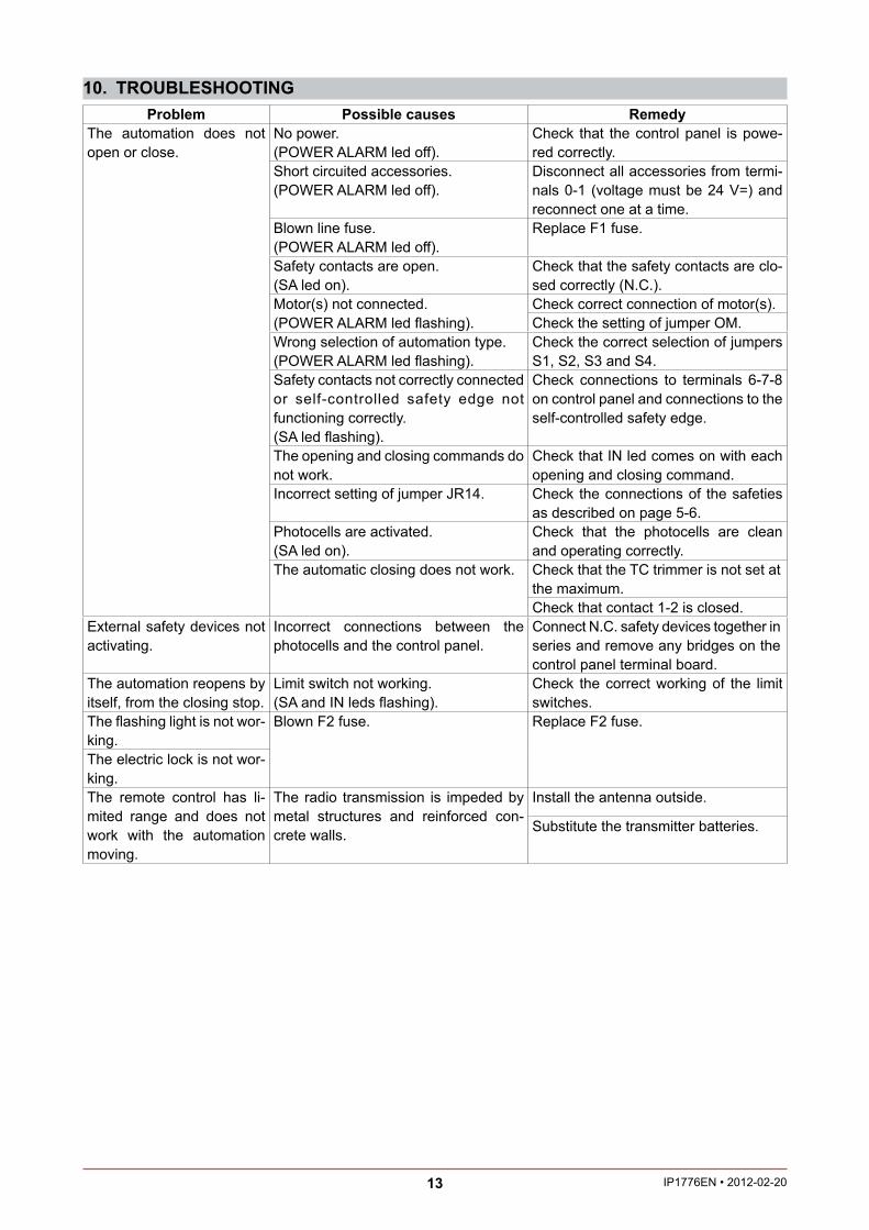
10. TROUBLESHOOTINGProblem Possible causes Remedy
The automation does not open or close.
No power.(POWER ALARM led off).
Chec that the control panel is powe-red correctly.
Short circuited accessories.(POWER ALARM led off).
Disconnect all accessories from termi-nals 0-1 (voltage must be 24 V=) and reconnect one at a time.
Blown line fuse.(POWER ALARM led off).
Replace F1 fuse.
Safety contacts are open.(SA led on).
Chec that the safety contacts are clo-sed correctly (N.C.).
Motor(s) not connected.(POWER ALARM led ashing).
Chec correct connection of motor(s).Chec the setting of jumper OM.
Wrong selection of automation type.(POWER ALARM led ashing).
Chec the correct selection of jumpers S1, S2, S3 and S4.
Safety contacts not correctly connected or self-controlled safety edge not functioning correctly.(SA led ashing).
Chec connections to terminals 6-7-8 on control panel and connections to the self-controlled safety edge.
The opening and closing commands do not wor .
Chec that IN led comes on with each opening and closing command.
Incorrect setting of jumper JR14. Chec the connections of the safeties as described on page 5-6.
Photocells are activated.(SA led on).
Chec that the photocells are clean and operating correctly.
The automatic closing does not wor . Chec that the TC trimmer is not set at the maximum.Chec that contact 1-2 is closed.
External safety devices not activating.
Incorrect connections between the photocells and the control panel.
Connect N.C. safety devices together in series and remove any bridges on the control panel terminal board.
The automation reopens by itself, from the closing stop.
Limit switch not wor ing.(SA and IN leds ashing).
Chec the correct wor ing of the limit switches.
The ashing light is not wor-ing.
Blown F2 fuse. Replace F2 fuse.
The electric loc is not wor-ing.
The remote control has li-mited range and does not wor with the automation moving.
The radio transmission is impeded by metal structures and reinforced con-crete walls.
Install the antenna outside.
Substitute the transmitter batteries.

14IP1776EN 2012-02-20
11. EXAMPLE APPLICATION FOR ONE-MOTOR AUTOMATIONS
Fig. 11.1
Fig. 11.2
Fig. 11.3
M136 35 34 33 32 31
24V=
Motor 1
+ - + -
OMOM=OFF
M1<MAX
1
M1(VM)
M1(VM)
max 10 s
1OPENING CLOSING
M136 35 34 33 32 31
24V=
Motor 1
+ - + -
OMOM=OFF
1N4007
M1=MAX
1
A
A
C
VMVM
max 10 s
max 10 s 1OPENING CLOSING
C
M136 35 34 33 32 31
24V=
Motor 1
+ - + -
OM
1N4007
FC
FC=OFF
M1<MAX
1
A
A
C
M1 (VM)
M1 (VM)
max 10 s
1OPENING CLOSING
C
OM=OFF
When the control panel is used in applications for au-tomations with one swinging door wing, for up-and-over doors or for sliding doors, these connections can be made:(Fig. 11.1) Use without limit switches. Set OM=OFF. Connect the motor as shown in the gure. NOTE: during the opening operation, the polarities
are those indicated in the gure. Set VM to the desired speed. Set M1 so as to obtain slow down of the door wing
before the mechanical stop. With the above connections the wing stops on the
opening and closing mechanical stop. When the time set with M1 runs out:
on opening operation the slow down time is a maximum of 10 s; on closing operation the wing slows down until it reaches the mechanical stop.
(Fig. 11.2) Use with slow down limit switches. Set OM=OFF. Connect the motor and slow down limit switches as
shown in the gure: A opening slow down limit switch; C closing slow down limit switch. Set VM to the desired speed. Set M1=MAX. With the above connections the wing stops on the
opening and closing mechanical stop. After the slow down limit switch has been triggered
on opening operation and on closing operation the maximum slow down time is 10 s.
(Fig. 11.3) Use with stop limit switch. Set OM=OFF and FC=OFF. Connect the motor and stop limit switches as shown
in the gure: A opening stop limit switch; C closing stop limit switch. NOTE: a single limit switch can also be installed. Set M1<MAX. Set VM to the desired speed. Set M1 so as to obtain slow down of the door wing
before the limit switch is triggered. With the above connections, the wing stops when
the limit switch operates. When the time set with M1 runs out:
on opening operation the slow down time is a maximum of 10 s; on closing operation the wing slows down until it reaches the stop limit switch.
15 IP1776EN 2012-02-20
Fig. 12.1
Fig. 12.2
Fig. 12.3
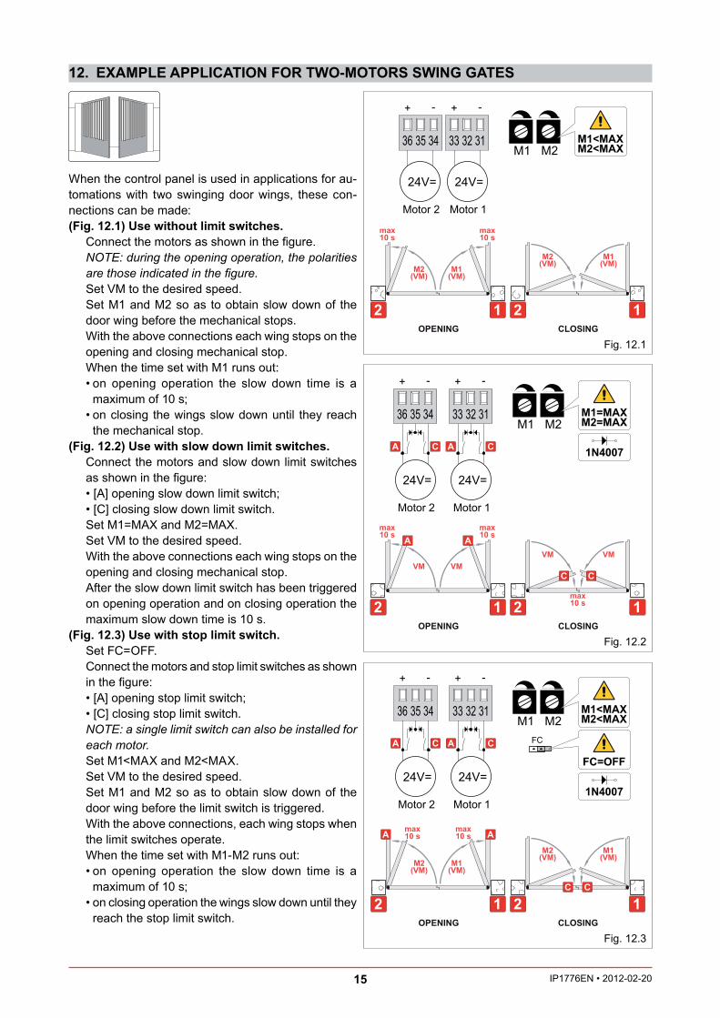
12. EXAMPLE APPLICATION FOR TWO-MOTORS SWING GATES
When the control panel is used in applications for au-tomations with two swinging door wings, these con-nections can be made:(Fig. 12.1) Use without limit switches. Connect the motors as shown in the gure. NOTE: during the opening operation, the polarities
are those indicated in the gure. Set VM to the desired speed. Set M1 and M2 so as to obtain slow down of the
door wing before the mechanical stops. With the above connections each wing stops on the
opening and closing mechanical stop. When the time set with M1 runs out:
on opening operation the slow down time is a maximum of 10 s; on closing the wings slow down until they reach the mechanical stop.
(Fig. 12.2) Use with slow down limit switches. Connect the motors and slow down limit switches
as shown in the gure: A opening slow down limit switch; C closing slow down limit switch. Set M1=MAX and M2=MAX. Set VM to the desired speed. With the above connections each wing stops on the
opening and closing mechanical stop. After the slow down limit switch has been triggered
on opening operation and on closing operation the maximum slow down time is 10 s.
(Fig. 12.3) Use with stop limit switch. Set FC=OFF. Connect the motors and stop limit switches as shown
in the gure: A opening stop limit switch; C closing stop limit switch. NOTE: a single limit switch can also be installed for
each motor. Set M1<MAX and M2<MAX. Set VM to the desired speed. Set M1 and M2 so as to obtain slow down of the
door wing before the limit switch is triggered. With the above connections, each wing stops when
the limit switches operate. When the time set with M1-M2 runs out:
on opening operation the slow down time is a maximum of 10 s; on closing operation the wings slow down until they reach the stop limit switch.
M1 M236 35 34 33 32 31
24V=
Motor 1
24V=
Motor 2
+ - + -
M1<MAXM2<MAX
12
M1(VM)
M1(VM)
M2(VM)
M2(VM)
max10 s
max10 s
OPENING
12CLOSING
24V=
Motor 1
A C
24V=
Motor 2
A C 1N4007
M1 M236 35 34 33 32 31
+ - + -
M1=MAXM2=MAX
12
VMVM
VMVM
max10 s
max10 s
max10 s
OPENING
12CLOSING
A A
C C
24V=
Motor 1
A C
24V=
Motor 2
A C
M1 M236 35 34 33 32 31
+ - + -
M1<MAXM2<MAX
12
M1(VM)
M2(VM)
M1(VM)
M2(VM)
max10 s
max10 s
OPENING
12CLOSING
A A
C C
1N4007
FC
FC=OFF
16IP1776EN 2012-02-20
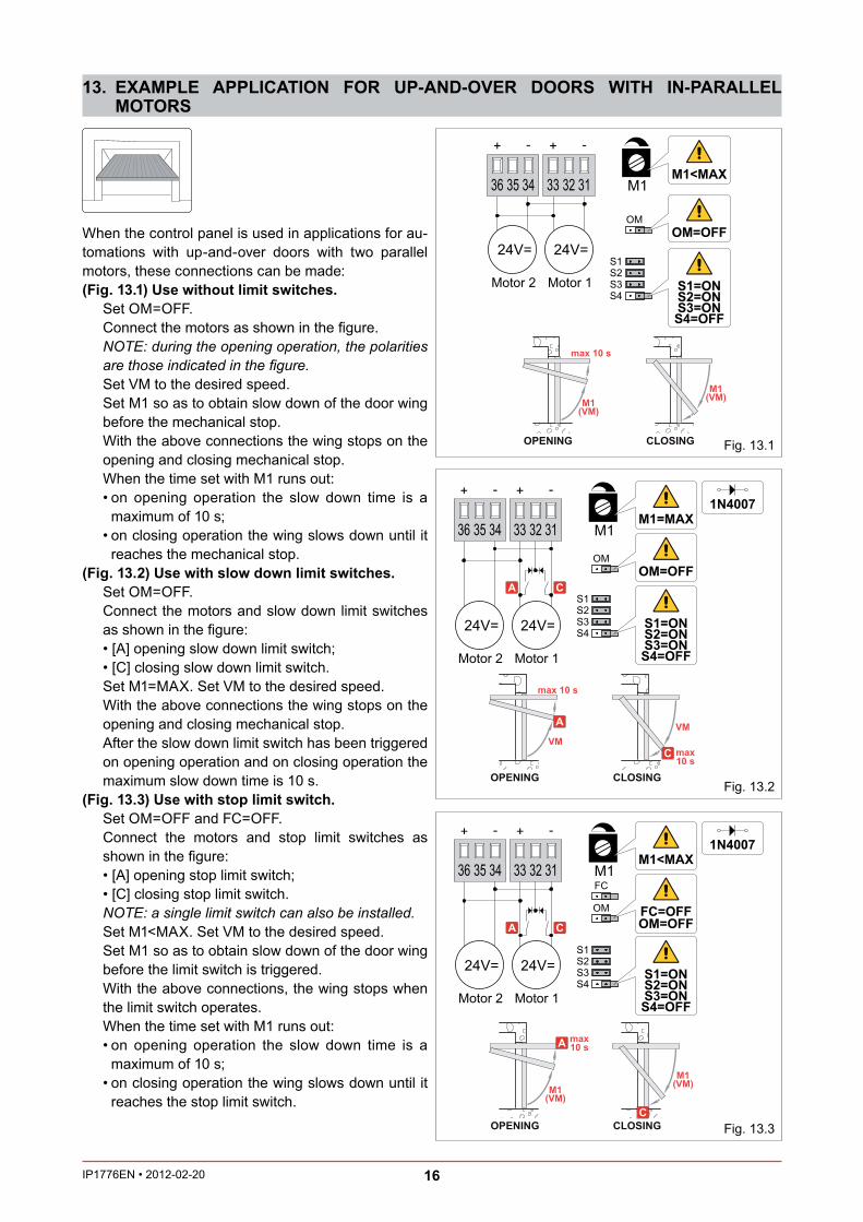
13. EXAMPLE APPLICATION FOR UP-AND-OVER DOORS WITH IN-PARALLEL MOTORS
M136 35 34 33 32 31
24V=
Motor 1
24V=
Motor 2
+ - + -
OMOM=OFF
S1=ONS2=ONS3=ONS4=OFF
M1<MAX
M1(VM)
M1(VM)
max 10 s
OPENING CLOSING
S1S2S3S4
M136 35 34 33 32 31
24V=
Motor 1
24V=
Motor 2
+ - + -
OMOM=OFF
S1=ONS2=ONS3=ONS4=OFF
M1=MAX
VMVM
max 10 s
OPENING CLOSING
S1S2S3S4
A
A
C
C max10 s
1N4007
OM
FC
FC=OFFOM=OFF
M136 35 34 33 32 31
24V=
Motor 1
24V=
Motor 2
+ - + -
S1=ONS2=ONS3=ONS4=OFF
M1<MAX
M1(VM)
M1(VM)
OPENING CLOSING
S1S2S3S4
A
A
C
C
max10 s
1N4007
When the control panel is used in applications for au-tomations with up-and-over doors with two parallel motors, these connections can be made:(Fig. 13.1) Use without limit switches. Set OM=OFF. Connect the motors as shown in the gure. NOTE: during the opening operation, the polarities
are those indicated in the gure. Set VM to the desired speed. Set M1 so as to obtain slow down of the door wing
before the mechanical stop. With the above connections the wing stops on the
opening and closing mechanical stop. When the time set with M1 runs out:
on opening operation the slow down time is a maximum of 10 s; on closing operation the wing slows down until it reaches the mechanical stop.
(Fig. 13.2) Use with slow down limit switches. Set OM=OFF. Connect the motors and slow down limit switches
as shown in the gure: A opening slow down limit switch; C closing slow down limit switch. Set M1=MAX. Set VM to the desired speed. With the above connections the wing stops on the
opening and closing mechanical stop. After the slow down limit switch has been triggered
on opening operation and on closing operation the maximum slow down time is 10 s.
(Fig. 13.3) Use with stop limit switch. Set OM=OFF and FC=OFF. Connect the motors and stop limit switches as
shown in the gure: A opening stop limit switch; C closing stop limit switch. NOTE: a single limit switch can also be installed. Set M1<MAX. Set VM to the desired speed. Set M1 so as to obtain slow down of the door wing
before the limit switch is triggered. With the above connections, the wing stops when
the limit switch operates. When the time set with M1 runs out:
on opening operation the slow down time is a maximum of 10 s; on closing operation the wing slows down until it reaches the stop limit switch.
Fig. 13.1
Fig. 13.2
Fig. 13.3

17 IP1776EN 2012-02-20

TM
DITEC S.p.A. Via Mons. Ban , 3 21042 Caronno P.lla (VA) Italy Tel. +39 02 963911 Fax +39 02 9650314www.ditec.it [email protected]
DITEC BELGIUM LOKEREN Tel. +32 9 3560051 Fax +32 9 3560052 www.ditecbelgium.be DITEC DEUTSCHLAND OBERURSELTel. +49 6171 914150 Fax +49 6171 9141555 www.ditec-germany.de DITEC ESPAÑA ARENYS DE MAR Tel. +34 937958399Fax +34 937959026 www.ditecespana.com DITEC FRANCE MASSY Tel. +33 1 64532860 Fax +33 1 64532861 www.ditecfrance.comDITEC GOLD PORTA ERMESINDE-PORTUGAL Tel. +351 22 9773520 Fax +351 22 9773528/38 www.goldporta.com DITEC SWITZERLANDBALERNA Tel. +41 848 558855 Fax +41 91 6466127 www.ditecswiss.ch DITEC ENTREMATIC NORDIC LANDSKRONA-SWEDENTel. +46 418 514 50 Fax +46 418 511 63 www.ditecentrematicnordic.com DITEC TURCHIA ISTANBUL Tel. +90 21 28757850Fax +90 21 28757798 www.ditec.com.tr DITEC AMERICA ORLANDO-FLORIDA-USA Tel. +1 407 8880699 Fax +1 407 8882237 www.ditecamerica.com DITEC CHINA SHANGHAI Tel. +86 21 62363861/2 Fax +86 21 62363863 www.ditec.cn