Embed Size (px)
Citation preview
Visual Modeling –
HL7 Challenges, Benefits,and Applications
(Is a Picture Worth 1000 Words?)
Charlie Mead, MD, MSc
Director, Healthcare Information ArchitectureOracle Healthcare
Director, HL7 Board of DirectorsCo-Chair, Patient Care Technical Committee
Co-Chair, Personnel Management Technical Committee
Slide - 2HL7 UK December 12, 2003
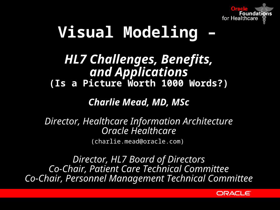
This is a model…
• Referral• Transportation• Supply• Procedure• Consent• Observation• Medication• Act complex• Financial act
• Organization• Place• Person• Living Subject• Material• Health Chart
• Patient• Member• Guardian• Healthcare facility• Practitioner• Location• Specimen
Entity
1
0..*
1
0..*
Role Link
0..*
1,1Role
1
0..*
1
0..*
ActRelationship
0..*
1
0..*
1Participation Act
• Subject• Beneficiary• Author• Consultant• Referrer• Informant• Witness
• Fulfills• Component• Supported by• Documents• Replaces
• Direct Authority• Indirect Authority• Part of• Replaces
Slide - 3HL7 UK December 12, 2003
…as is this…
RIMBig.gif
Slide - 4HL7 UK December 12, 2003
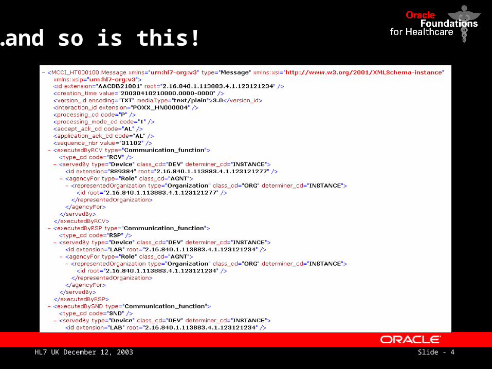
…and so is this!
Slide - 5HL7 UK December 12, 2003
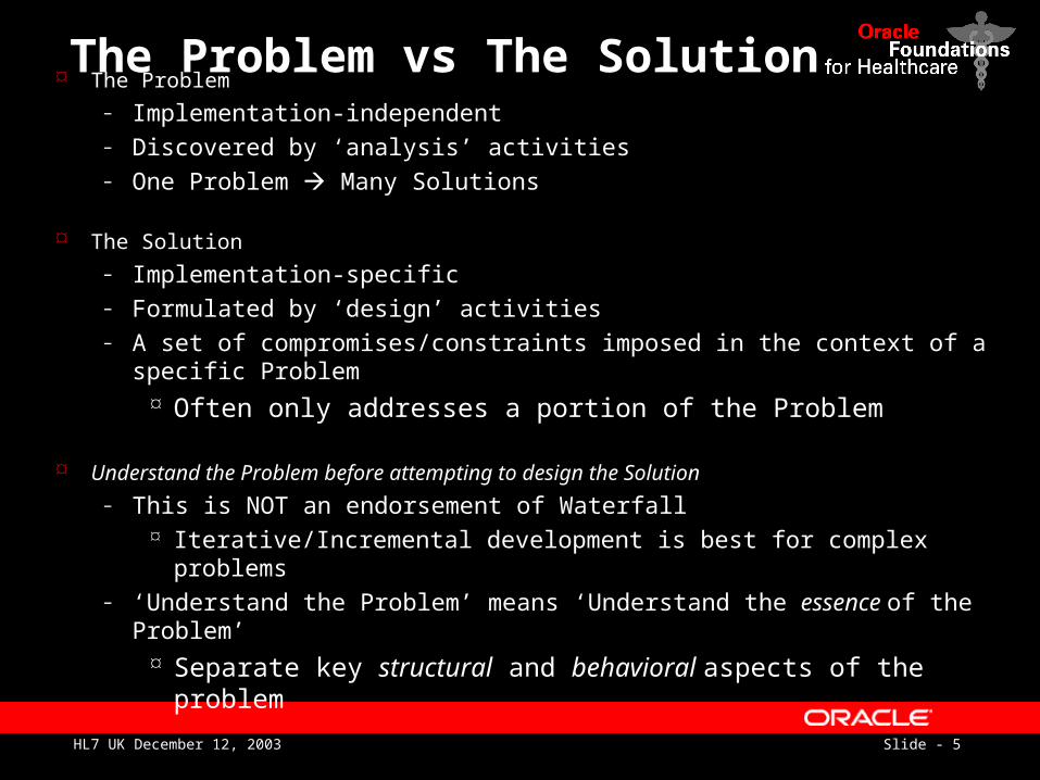
The Problem vs The Solution The Problem
– Implementation-independent– Discovered by ‘analysis’ activities– One Problem Many Solutions
The Solution
– Implementation-specific– Formulated by ‘design’ activities– A set of compromises/constraints imposed in the context of a specific
Problem Often only addresses a portion of the Problem
Understand the Problem before attempting to design the Solution
– This is NOT an endorsement of Waterfall Iterative/Incremental development is best for complex problems
– ‘Understand the Problem’ means ‘Understand the essence of the Problem’ Separate key structural and behavioral aspects of the problem
Slide - 6HL7 UK December 12, 2003
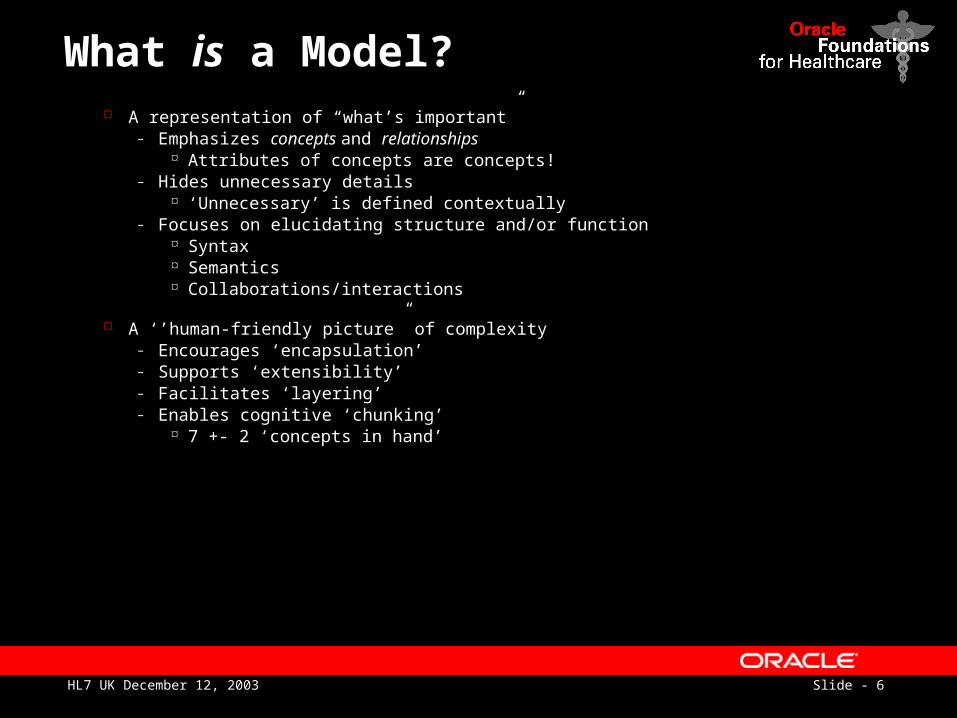
What is a Model? A representation of “what’s important”
– Emphasizes concepts and relationships Attributes of concepts are concepts!
– Hides unnecessary details ‘Unnecessary’ is defined contextually
– Focuses on elucidating structure and/or function Syntax Semantics Collaborations/interactions
A ‘’human-friendly picture” of complexity– Encourages ‘encapsulation’– Supports ‘extensibility’– Facilitates ‘layering’– Enables cognitive ‘chunking’
7 +- 2 ‘concepts in hand’
Slide - 7HL7 UK December 12, 2003
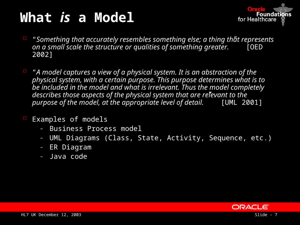
What is a Model
“Something that accurately resembles something else; a thing that represents on a small scale the structure or qualities of something greater.” [OED 2002]
“A model captures a view of a physical system. It is an abstraction of the physical system, with a certain purpose. This purpose determines what is to be included in the model and what is irrelevant. Thus the model completely describes those aspects of the physical system that are relevant to the purpose of the model, at the appropriate level of detail.” [UML 2001]
Examples of models– Business Process model– UML Diagrams (Class, State, Activity, Sequence, etc.)– ER Diagram– Java code
Slide - 8HL7 UK December 12, 2003
What is a Model?
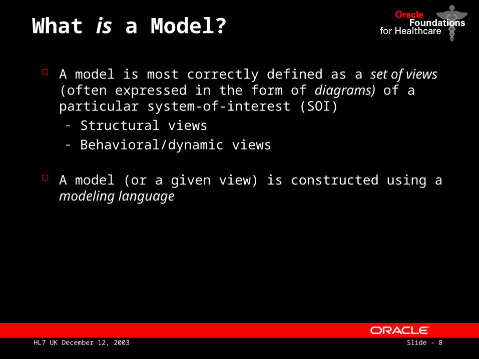
A model is most correctly defined as a set of views (often expressed in the form of diagrams) of a particular system-of-interest (SOI)
– Structural views– Behavioral/dynamic views
A model (or a given view) is constructed using a modeling language
Slide - 9HL7 UK December 12, 2003
What is a Modeling Language?
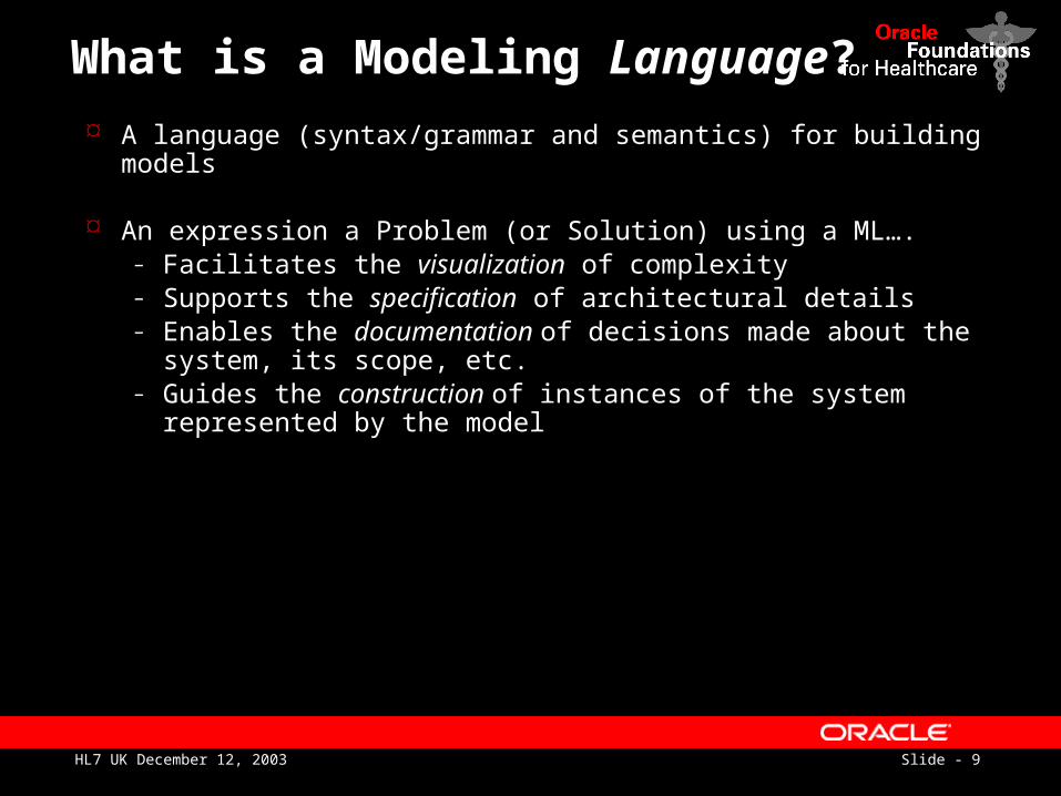
A language (syntax/grammar and semantics) for building models
An expression a Problem (or Solution) using a ML….– Facilitates the visualization of complexity– Supports the specification of architectural details– Enables the documentation of decisions made about the
system, its scope, etc.– Guides the construction of instances of the system
represented by the model
Slide - 10HL7 UK December 12, 2003
What is a visual Model?
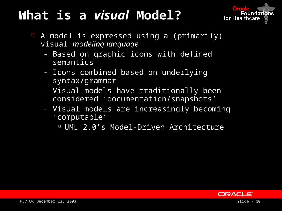
A model is expressed using a (primarily) visual modeling language
– Based on graphic icons with defined semantics– Icons combined based on underlying
syntax/grammar– Visual models have traditionally been considered
‘documentation/snapshots’– Visual models are increasingly becoming
‘computable’ UML 2.0’s Model-Driven Architecture
Slide - 11HL7 UK December 12, 2003
Why model?
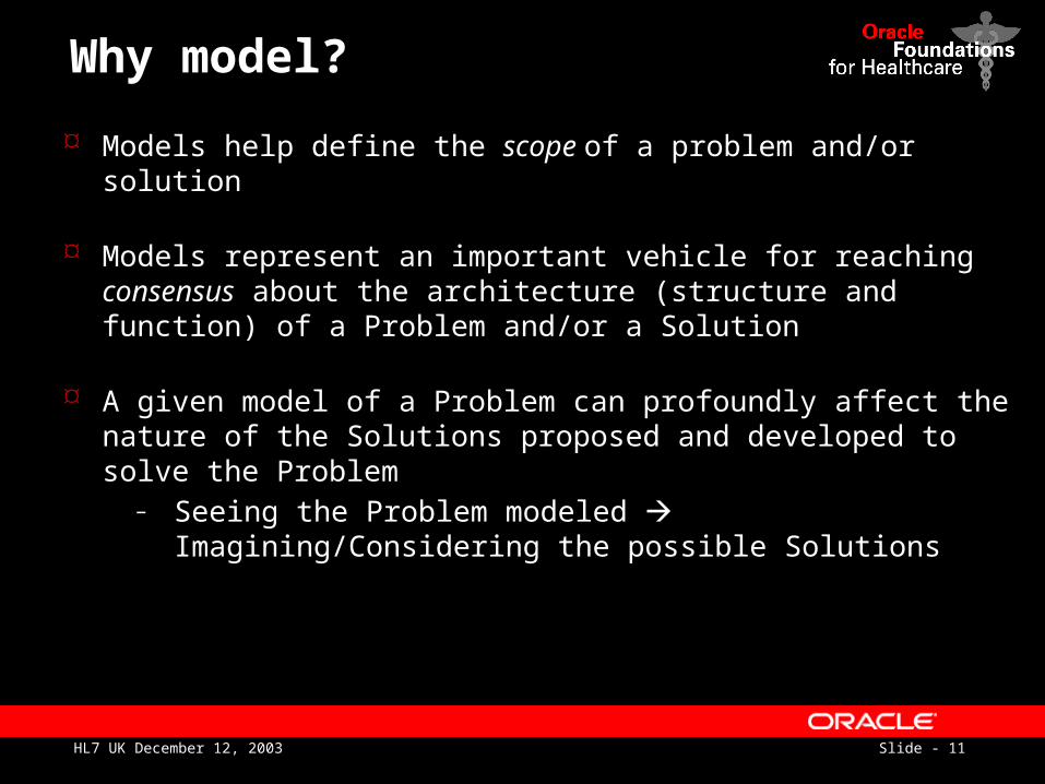
Models help define the scope of a problem and/or solution
Models represent an important vehicle for reaching consensus about the architecture (structure and function) of a Problem and/or a Solution
A given model of a Problem can profoundly affect the nature of the Solutions proposed and developed to solve the Problem
– Seeing the Problem modeled Imagining/Considering the possible Solutions
Slide - 12HL7 UK December 12, 2003
Why model?
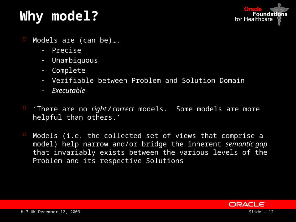
Models are (can be)….– Precise– Unambiguous– Complete– Verifiable between Problem and Solution Domain – Executable
‘There are no right / correct models. Some models are more helpful than others.’
Models (i.e. the collected set of views that comprise a model) help narrow and/or bridge the inherent semantic gap that invariably exists between the various levels of the Problem and its respective Solutions
Slide - 13HL7 UK December 12, 2003
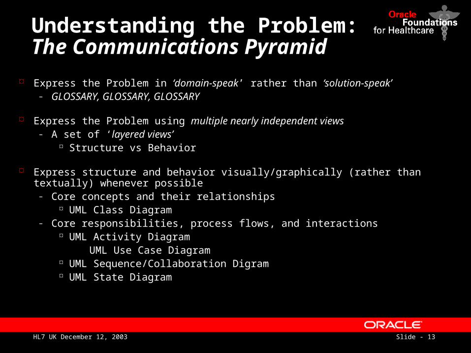
Understanding the Problem:The Communications Pyramid
Express the Problem in ‘domain-speak’ rather than ‘solution-speak’– GLOSSARY, GLOSSARY, GLOSSARY
Express the Problem using multiple nearly independent views– A set of ‘layered views’
Structure vs Behavior
Express structure and behavior visually/graphically (rather than textually) whenever possible
– Core concepts and their relationships UML Class Diagram
– Core responsibilities, process flows, and interactions UML Activity Diagram
UML Use Case Diagram UML Sequence/Collaboration Digram UML State Diagram
Slide - 14HL7 UK December 12, 2003
`
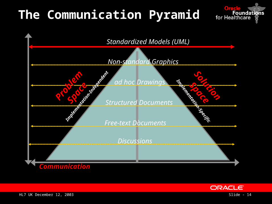
The Communication Pyramid
Communication
Free-text Documents
Structured Documents
ad hoc Drawings
Non-standard Graphics
Discussions
Standardized Models (UML)
Probl
em
Probl
em
Space
Space
Solution
Solution
Space
SpaceIm
plem
enta
tion-
Inde
pend
ent
Implem
entation-Specific
Slide - 15HL7 UK December 12, 2003
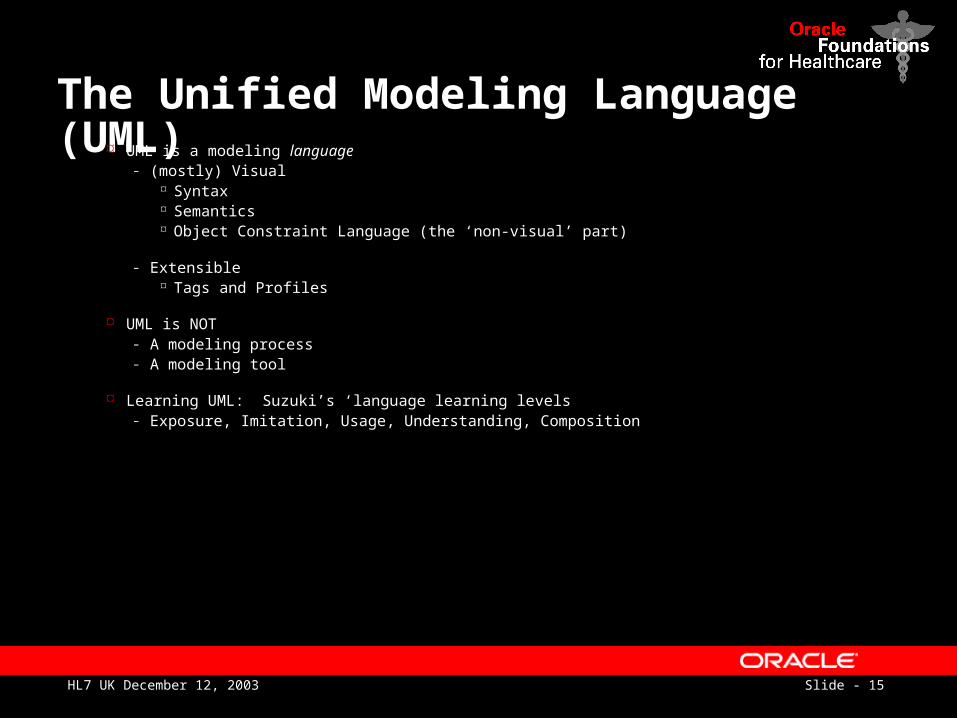
The Unified Modeling Language (UML) UML is a modeling language
– (mostly) Visual Syntax Semantics Object Constraint Language (the ‘non-visual’ part)
– Extensible Tags and Profiles
UML is NOT– A modeling process– A modeling tool
Learning UML: Suzuki’s ‘language learning levels– Exposure, Imitation, Usage, Understanding, Composition
Slide - 16HL7 UK December 12, 2003
The UML is… A well-defined (mostly) visual language for describing the structure and/or function of complex
systems.– A language supporting well-formed models
The UML is a language that facilitates….– ….visualizing complexity– ….specifying relationships and interactions– ….guiding the construction of the modeled system– ….documenting the decisions made about the modeled system
The de facto modeling language standard managed, maintained, and evolved by the Object Management Group (omg.org)
– 10-15 years in develop– Convergence of multiple perspectives and agendas
Slide - 17HL7 UK December 12, 2003
Primary Design Goals of the UML
Provide users with a ready-to-use, expressive visual modeling language to develop and exchange meaningful models
Furnish extensibility and specialization mechanisms to extend the core concepts
– e.g. HL7 Profile
Provide a formal basis for understanding the modeling language
Encourage the growth of the object-orient tools market
Support higher-level development concepts such as components, collaborations, frameworks and patterns
Integrate best practices in complex system development
Slide - 18HL7 UK December 12, 2003
UML Building Blocks
Things– Classes– Objects– Activities
Relationships– Syntactic– Semantic
Diagrams– Static Structure– Dynamic Behavior
Slide - 19HL7 UK December 12, 2003
UML Model Views
Static Diagrams– Class Diagram– Object Diagram– Implementation Diagrams
Deployment Diagram Component Diagram
Behavioral Diagrams– Use Case Diagram– Activity Diagram– State-chart Diagram– Activity Diagram– Interaction Diagrams
Sequence Diagram Collaboration Diagram
Slide - 20HL7 UK December 12, 2003
The RIM and Modeling
RIMBig.gif
PRPA_NA000002.gif
QUQI_NA000001.gif
Slide - 21HL7 UK December 12, 2003
DMIMs, RMIMs and Modeling
PM DMIM 03-nov-12 visio5.vsd
RMIM1.gif RMIM3.gif RMIM5.gif RMIM6.gif RMIMSimple.gif
‘Increasing constraints on the RIM’– Class– Attributes– Relationships– Multiplicities– Data Types– Vocabulary
Slide - 22HL7 UK December 12, 2003
The HL7 Development Framework (HDF): What Models Should We Build?
The HDF recognizes the importance of separating analysis activities from design activities
– Use ‘domain-friendly’ terms to build ‘analysis’ views– ‘Map’ analysis views to design views
A given concept or relationship in the Domain Analysis model may map to a RIM
Class Attribute Vocabulary
Slide - 23HL7 UK December 12, 2003
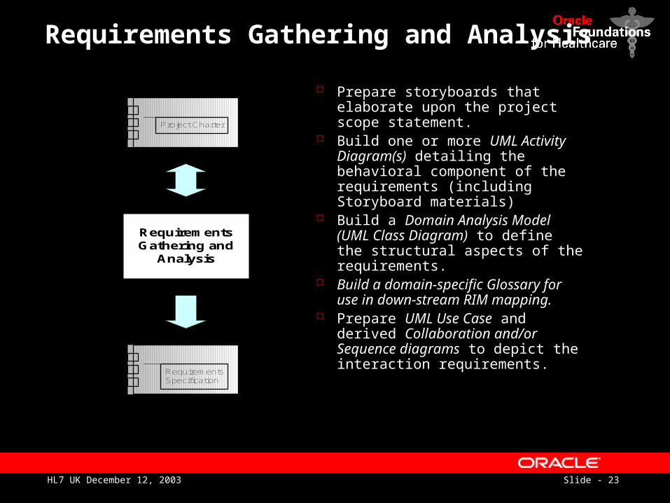
Requirements Gathering and Analysis
RequirementsGathering and
Analysis
RequirementsSpecification
Project Charter
Prepare storyboards that elaborate upon the project scope statement.
Build one or more UML Activity Diagram(s) detailing the behavioral component of the requirements (including Storyboard materials)
Build a Domain Analysis Model (UML Class Diagram) to define the structural aspects of the requirements.
Build a domain-specific Glossary for use in down-stream RIM mapping.
Prepare UML Use Case and derived Collaboration and/or Sequence diagrams to depict the interaction requirements.
Slide - 24HL7 UK December 12, 2003
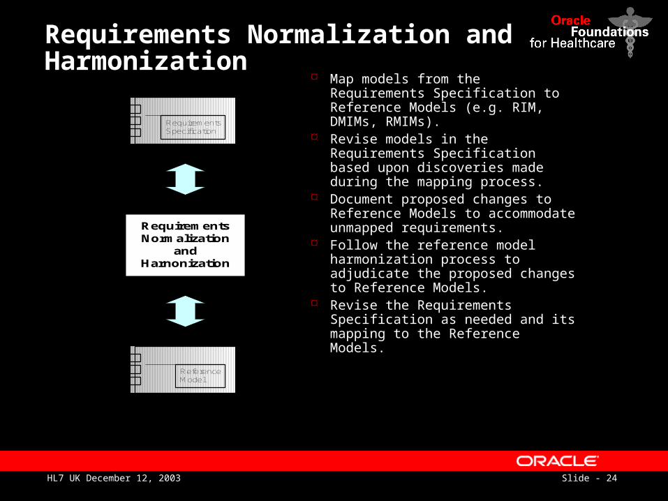
Requirements Normalization and Harmonization
RequirementsNormalization
andHarnonization
RequirementsSpecification
ReferenceModel
Map models from the Requirements Specification to Reference Models (e.g. RIM, DMIMs, RMIMs).
Revise models in the Requirements Specification based upon discoveries made during the mapping process.
Document proposed changes to Reference Models to accommodate unmapped requirements.
Follow the reference model harmonization process to adjudicate the proposed changes to Reference Models.
Revise the Requirements Specification as needed and its mapping to the Reference Models.
Slide - 25HL7 UK December 12, 2003
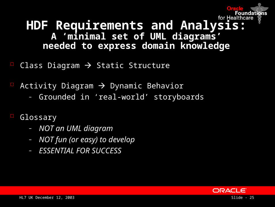
HDF Requirements and Analysis:A ‘minimal set of UML diagrams’
needed to express domain knowledge
Class Diagram Static Structure
Activity Diagram Dynamic Behavior– Grounded in ‘real-world’ storyboards
Glossary– NOT an UML diagram– NOT fun (or easy) to develop– ESSENTIAL FOR SUCCESS
Slide - 26HL7 UK December 12, 2003
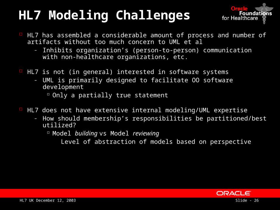
HL7 Modeling Challenges
HL7 has assembled a considerable amount of process and number of artifacts without too much concern to UML et al
– Inhibits organization’s (person-to-person) communication with non-healthcare organizations, etc.
HL7 is not (in general) interested in software systems– UML is primarily designed to facilitate OO software development
Only a partially true statement
HL7 does not have extensive internal modeling/UML expertise– How should membership’s responsibilities be partitioned/best utilized?
Model building vs Model reviewing Level of abstraction of models based on perspective
Slide - 27HL7 UK December 12, 2003
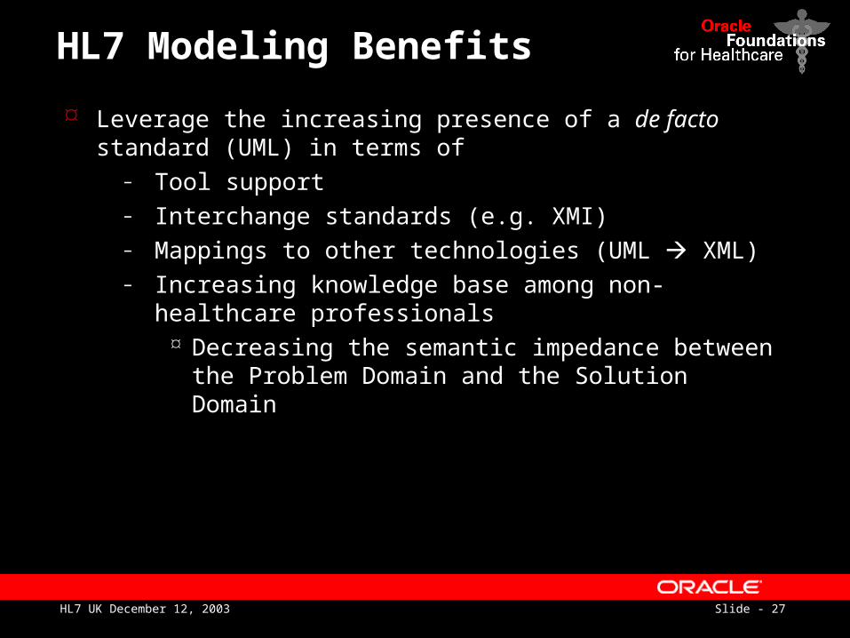
HL7 Modeling Benefits
Leverage the increasing presence of a de facto standard (UML) in terms of
– Tool support– Interchange standards (e.g. XMI)– Mappings to other technologies (UML XML)– Increasing knowledge base among non-healthcare
professionals Decreasing the semantic impedance between the
Problem Domain and the Solution Domain
Slide - 28HL7 UK December 12, 2003
HL7 Modeling Applications:Past, Present, Future
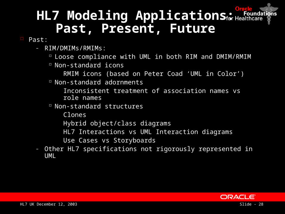
Past:– RIM/DMIMs/RMIMs:
Loose compliance with UML in both RIM and DMIM/RMIM Non-standard icons
RMIM icons (based on Peter Coad ‘UML in Color’) Non-standard adornments
Inconsistent treatment of association names vs role names Non-standard structures
Clones Hybrid object/class diagrams HL7 Interactions vs UML Interaction diagrams Use Cases vs Storyboards
– Other HL7 specifications not rigorously represented in UML
Slide - 29HL7 UK December 12, 2003
HL7 Modeling Applications:Past, Present, Future
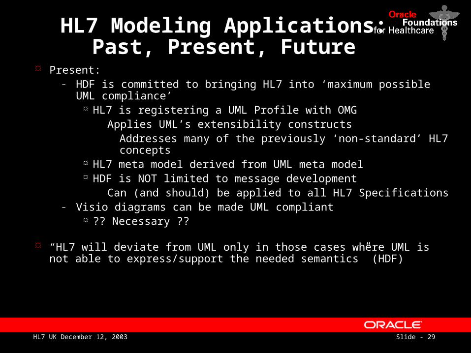
Present:– HDF is committed to bringing HL7 into ‘maximum possible UML
compliance’ HL7 is registering a UML Profile with OMG
Applies UML’s extensibility constructs Addresses many of the previously ‘non-standard’ HL7 concepts
HL7 meta model derived from UML meta model HDF is NOT limited to message development
Can (and should) be applied to all HL7 Specifications– Visio diagrams can be made UML compliant
?? Necessary ??
“HL7 will deviate from UML only in those cases where UML is not able to express/support the needed semantics” (HDF)
Slide - 30HL7 UK December 12, 2003
HL7 Modeling Applications:Past, Present, Future
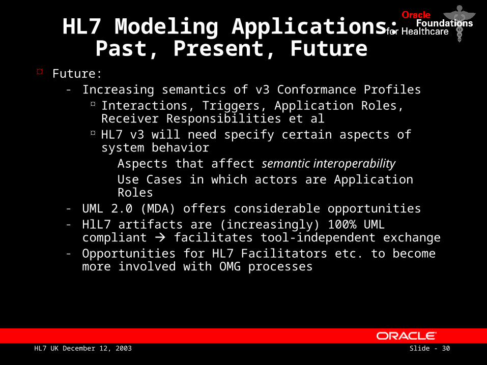
Future:– Increasing semantics of v3 Conformance Profiles
Interactions, Triggers, Application Roles, Receiver Responsibilities et al
HL7 v3 will need specify certain aspects of system behavior
Aspects that affect semantic interoperability Use Cases in which actors are Application Roles
– UML 2.0 (MDA) offers considerable opportunities– HlL7 artifacts are (increasingly) 100% UML compliant
facilitates tool-independent exchange– Opportunities for HL7 Facilitators etc. to become more
involved with OMG processes
Slide - 31HL7 UK December 12, 2003
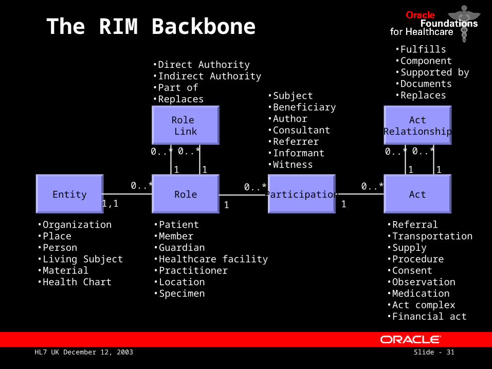
The RIM Backbone
• Referral• Transportation• Supply• Procedure• Consent• Observation• Medication• Act complex• Financial act
• Organization• Place• Person• Living Subject• Material• Health Chart
• Patient• Member• Guardian• Healthcare facility• Practitioner• Location• Specimen
Entity
1
0..*
1
0..*
Role Link
0..*
1,1Role
1
0..*
1
0..*
ActRelationship
0..*
1
0..*
1Participation Act
• Subject• Beneficiary• Author• Consultant• Referrer• Informant• Witness
• Fulfills• Component• Supported by• Documents• Replaces
• Direct Authority• Indirect Authority• Part of• Replaces
Slide - 32HL7 UK December 12, 2003
References
www.omg.org– The core UML site including UML 2.0
www.ectoset.com– Affordable (<$100) UML modeling tool
www.rational.com– White papers on tools and the use of the UML in
building ‘real-world’ systems
Slide - 33HL7 UK December 12, 2003