Embed Size (px)
Citation preview
Visual Building - Fire Escape Plan Design
1
Visual Building
Fire Escape Plan
Design
Visual Building - Fire Escape Plan Design
2
INDEMNITY
This document and associated software has been produced as a tool to assist you in
completing various floor plans associated with a fire safety risk assessment of your premises.
It is used entirely at your own risk to produce suitable plans, and also whether you consider
the information therein to be suitable and sufficient. It is in no way exhaustive and Visual
Building Ltd accepts no liability for any circumstances which may arise as a result of using
this tool.
Copyright Visual Building Ltd 2014
Published: April 15th 2013
Updated: February 25th 2014
The BSI ISO 7010 symbols shown in this document are the copyright of BSI Group
Permission to reproduce extracts from British Standards is granted by the BSI Standards
Limited (BSI). No other use of this material is permitted. British Standards can be obtained
in PDF or hard copy formats from the BSI online shop: http://shop.bsigroup.com or by
contacting BSI Customer Services for hard copies only: Tel: +44 (0)20 8996 9001, Email:
Visual Building - Fire Escape Plan Design
3
Contents
1 Installing ..................................................................................................................................... 5
2 Fire Escape Plans ......................................................................................................................... 9
3 Requirements ........................................................................................................................... 11
3.1 Fire Escape Plan Catalogue ............................................................................................... 11
3.2 Fire Escape Plan Project templates ................................................................................... 12
3.2.1 Areas Folder ................................................................................................................. 13
3.2.2 Directions Folder .......................................................................................................... 13
3.3 Fire Extinguisher Folder .................................................................................................... 14
3.4 Fire Signs Folder ............................................................................................................... 15
3.5 Frames Folder .................................................................................................................. 15
3.6 Information Folder ........................................................................................................... 15
3.7 ISO 7010 E Folder ............................................................................................................. 16
3.8 ISO 7010 F Folder ............................................................................................................. 16
4 Overview................................................................................................................................... 17
4.1 Layers .............................................................................................................................. 18
4.1.1 Floor plan ..................................................................................................................... 18
4.1.2 Frame........................................................................................................................... 18
4.1.3 Fire Escape Plan ........................................................................................................... 19
4.1.4 Key Plan ....................................................................................................................... 20
4.1.5 Risk Plan ....................................................................................................................... 21
4.1.6 Extinguisher Plan .......................................................................................................... 22
4.1.7 Additional Layers .......................................................................................................... 22
4.1.8 Guidelines .................................................................................................................... 22
5 Create a Fire Escape Plan .......................................................................................................... 24
5.1 Locate Fire Escape Plan Catalogue .................................................................................... 24
5.2 Paper Size ........................................................................................................................ 24
5.3 Scale ................................................................................................................................ 24
5.4 Orientation ...................................................................................................................... 25
5.5 Select a Template............................................................................................................. 25
5.6 Drawing the Floor plan ..................................................................................................... 27
5.6.1 Setting wall thickness ................................................................................................... 28
Visual Building - Fire Escape Plan Design
4
5.6.2 Setting wall colour........................................................................................................ 29
5.6.3 Draw exterior walls ...................................................................................................... 30
5.6.4 Draw interior walls ....................................................................................................... 31
5.6.5 Position your plan ........................................................................................................ 31
5.6.6 Place Doors .................................................................................................................. 32
5.6.7 Place Escape Routes Area ............................................................................................. 33
5.6.8 Place Escape Route Direction Arrows ........................................................................... 34
5.6.9 Place You are Here ....................................................................................................... 35
5.6.10 Place Fire Signs ......................................................................................................... 35
5.6.11 Place Fire Fighting equipment .................................................................................. 36
5.6.12 Place Legend ............................................................................................................ 36
5.6.13 Place Overview ......................................................................................................... 36
5.6.14 Place Safety Notice ................................................................................................... 36
5.6.15 Create a Key Plan...................................................................................................... 36
5.6.16 Create a Risk Plan ..................................................................................................... 38
5.6.17 Create an Extinguisher Plan ...................................................................................... 39
6 Printing ..................................................................................................................................... 40
7 Creating your own symbols ....................................................................................................... 41
7.1 2D Objects v 2D Images .................................................................................................... 44
8 Stair Catalogue .......................................................................................................................... 46
9 Multiple Floors .......................................................................................................................... 48
10 Creating your own Title Panels .................................................................................................. 50
11 Fire Action Plates ...................................................................................................................... 52
11.1 Creating an Action Plate ................................................................................................... 52
12 INDEMNITY ............................................................................................................................... 56
Visual Building - Fire Escape Plan Design
5
1 Installing
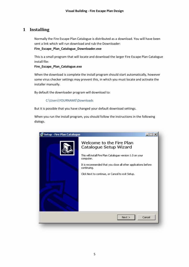
Normally the Fire Escape Plan Catalogue is distributed as a download. You will have been
sent a link which will run download and rub the Downloader:
Fire_Escape_Plan_Catalogue_Downloader.exe
This is a small program that will locate and download the larger Fire Escape Plan Catalogue
install file:
Fire_Escape_Plan_Catalogue.exe
When the download is complete the install program should start automatically, however
some virus checker settings may prevent this, in which you must locate and activate the
installer manually.
By default the downloader program will download to:
C:\Users\YOURNAME\Downloads
But it is possible that you have changed your default download settings.
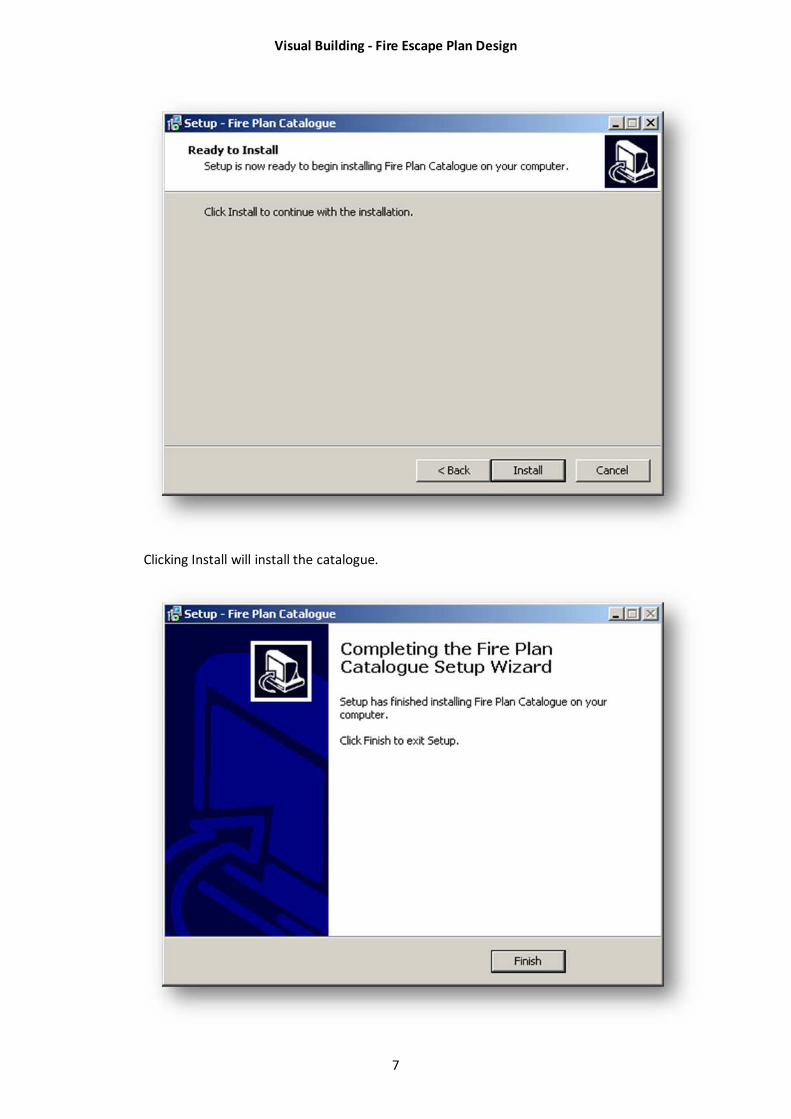
When you run the install program, you should follow the instructions in the following
dialogs.
Visual Building - Fire Escape Plan Design
6
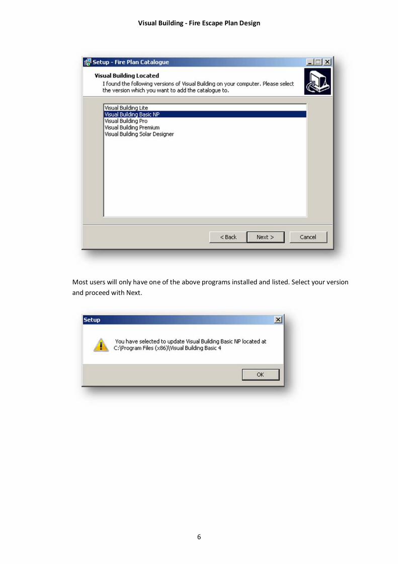
Most users will only have one of the above programs installed and listed. Select your version
and proceed with Next.
Visual Building - Fire Escape Plan Design
7
Clicking Install will install the catalogue.

Visual Building - Fire Escape Plan Design
8
The installer will have added a new folder called Fire Escape to the following path:
C:\Program Files (x86)\Visual Building Basic 4\Graphics2D
This path will vary depending upon your Windows version and Visual Building version.
The project templates that you will use are installed in a folder called Fire Escape Plan
Templates at the following path:
C:\Program Files (x86)\Visual Building Basic 4\Projects
This path will vary depending upon your Windows version and Visual Building version.
Visual Building - Fire Escape Plan Design
9
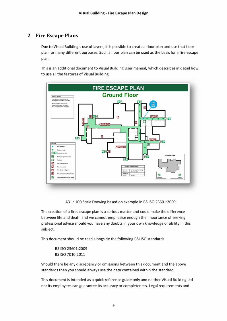
2 Fire Escape Plans
Due to Visual Building’s use of layers, it is possible to create a floor plan and use that floor
plan for many different purposes. Such a floor plan can be used as the basis for a fire escape
plan.
This is an additional document to Visual Building User manual, which describes in detail how
to use all the features of Visual Building.
A3 1: 100 Scale Drawing based on example in BS ISO 23601:2009
The creation of a fires escape plan is a serious matter and could make the difference
between life and death and we cannot emphasise enough the importance of seeking
professional advice should you have any doubts in your own knowledge or ability in this
subject.
This document should be read alongside the following BSI ISO standards:
BS ISO 23601:2009
BS ISO 7010:2011
Should there be any discrepancy or omissions between this document and the above
standards then you should always use the data contained within the standard.
This document is intended as a quick reference guide only and neither Visual Building Ltd
nor its employees can guarantee its accuracy or completeness. Legal requirements and

Visual Building - Fire Escape Plan Design
10
standards are constantly changing and we therefore request that you refer to a competent
and qualified authority and relevant standards.
Visual Building - Fire Escape Plan Design
11
3 Requirements
To create an Escape plan you will need the following:
Visual Building Basic (preferred, but any version of Visual Building is suitable)
Visual Building Fire Escape Plan Catalogue
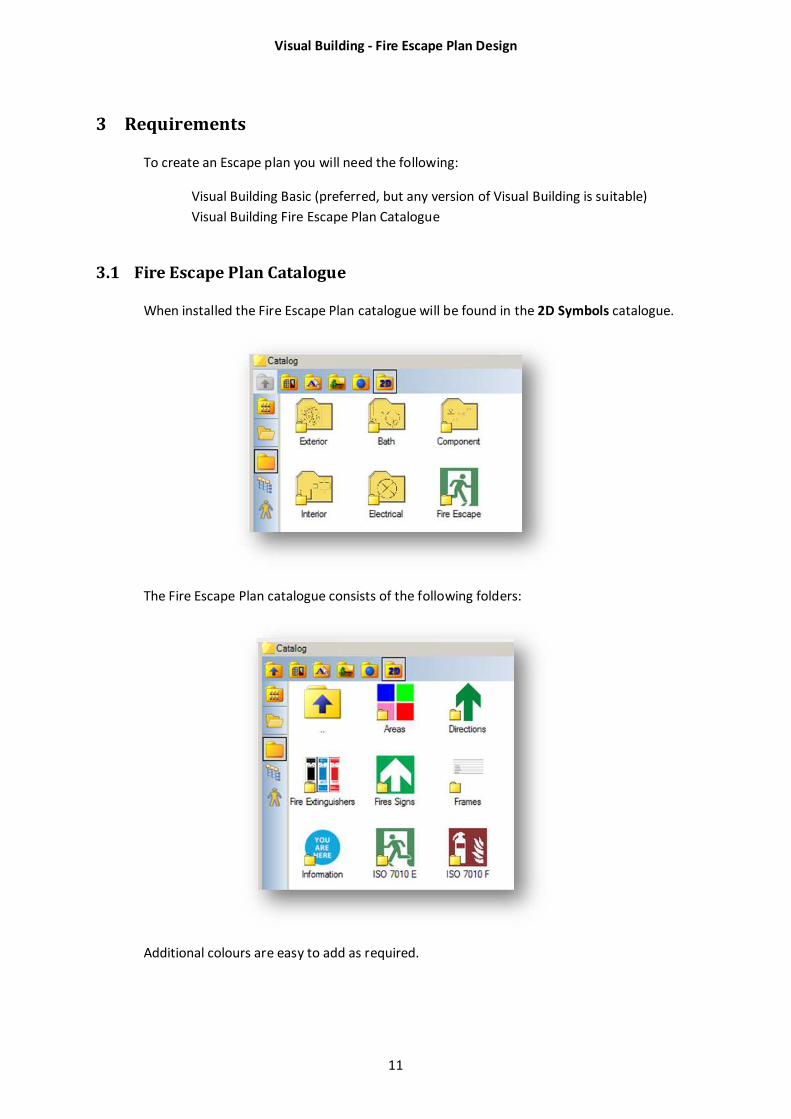
3.1 Fire Escape Plan Catalogue
When installed the Fire Escape Plan catalogue will be found in the 2D Symbols catalogue.
The Fire Escape Plan catalogue consists of the following folders:
Additional colours are easy to add as required.
Visual Building - Fire Escape Plan Design
12
3.2 Fire Escape Plan Project templates
Templates are easy to create for all combinations of paper size, orientation and scale, but
we have included the most common ones within the Fire Escape Plan Catalogue.
Template name Size Orientation Scale
EscapePlanTemplateA4L100 A4 Landscape 1:100
EscapePlanTemplateA4L250 A4 Landscape 1:250
EscapePlanTemplateA4L350 A4 Landscape 1:350
EscapePlanTemplateA4P100 A4 Portrait 1:100
EscapeplanTemplateA3L100 A3 Landscape 1:100
EscapeplanTemplateA3P100 A3 Portrait 1:100
These templates include the Escape Plan header set to the recommended minimum text
size.
The templates also include several pre-defined layers which allow you to use the floor plans
for purposes other than escape plans.
The templates are located in the Visual Building Projects folder which will have a path name
similar to (depending upon your system and install options):
C:\Program Files (x86)\Visual Building Basic\Projects\Fire Escape Plan Templates
C:\Program Files\Visual Building Basic\Projects\Fire Escape Plan Templates
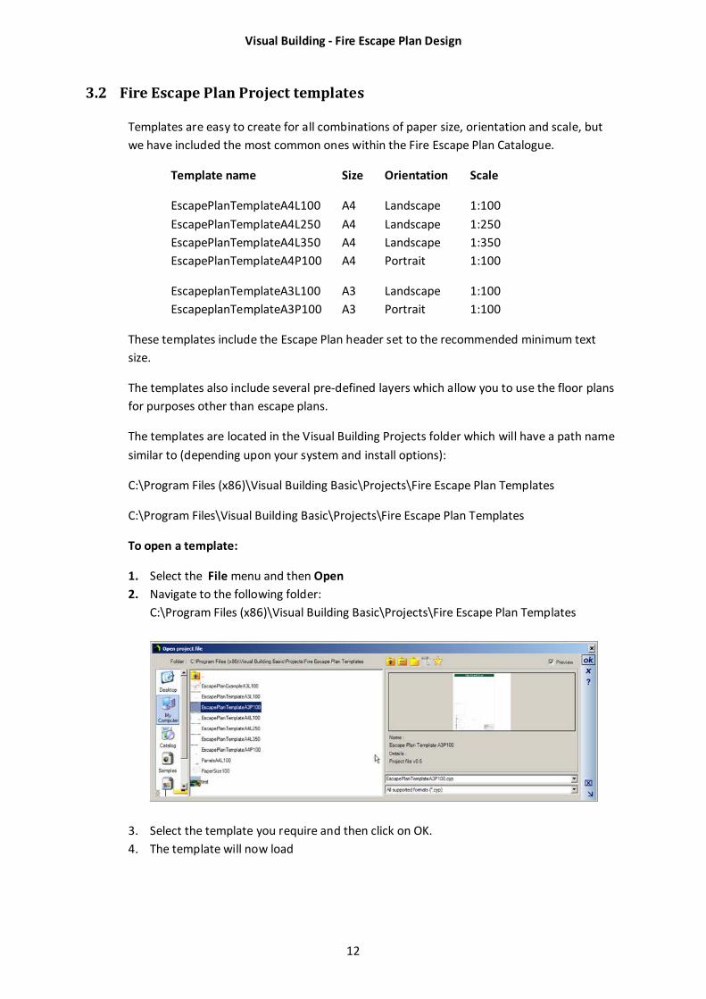
To open a template:
1. Select the File menu and then Open
2. Navigate to the following folder:
C:\Program Files (x86)\Visual Building Basic\Projects\Fire Escape Plan Templates
3. Select the template you require and then click on OK.
4. The template will now load
Visual Building - Fire Escape Plan Design
13
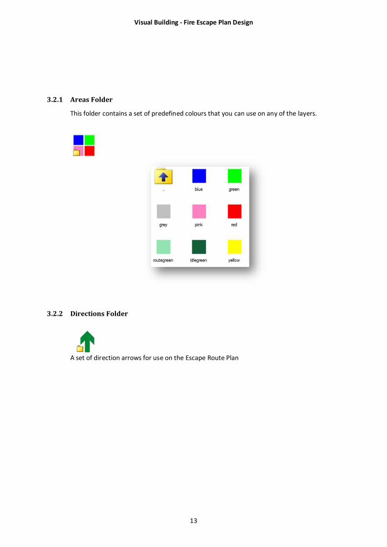
3.2.1 Areas Folder
This folder contains a set of predefined colours that you can use on any of the layers.
3.2.2 Directions Folder
A set of direction arrows for use on the Escape Route Plan
Visual Building - Fire Escape Plan Design
14
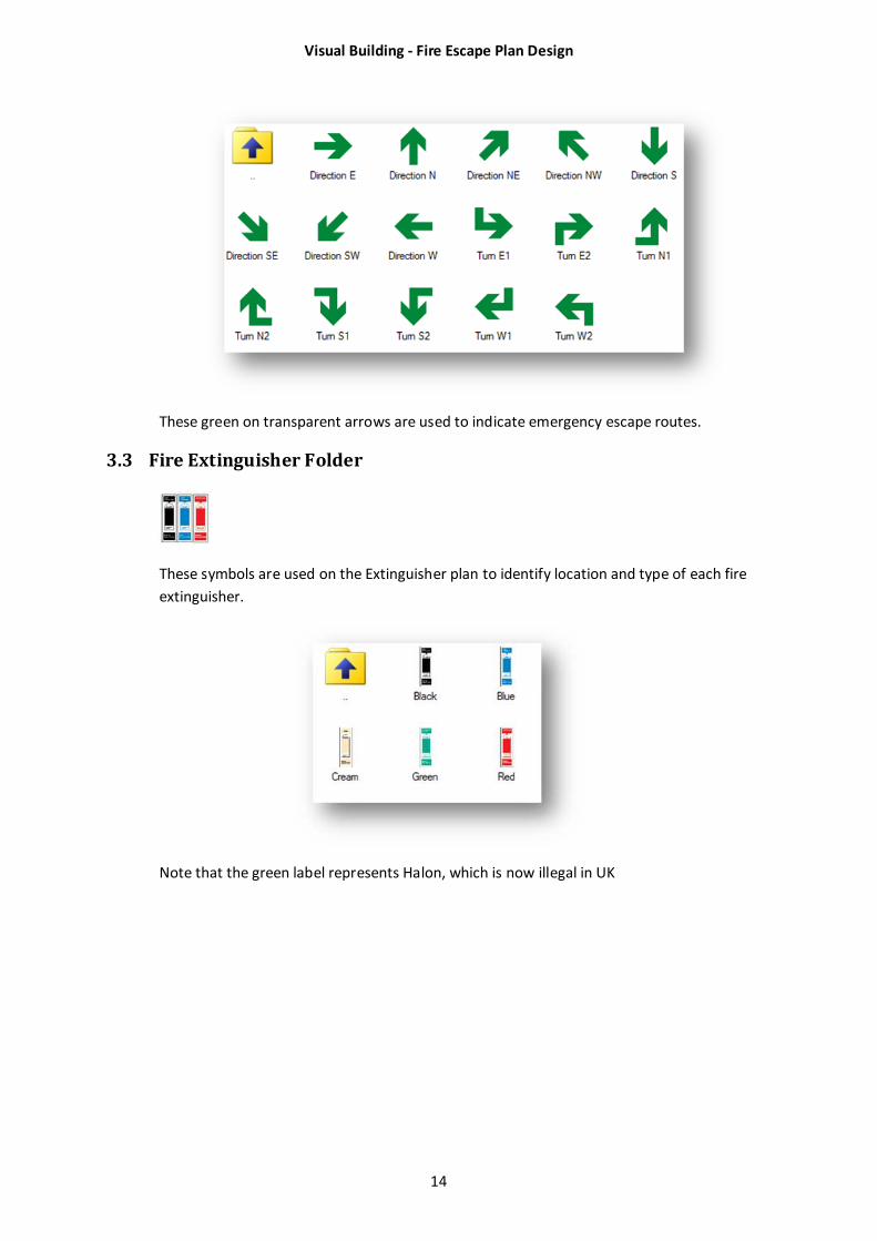
These green on transparent arrows are used to indicate emergency escape routes.
3.3 Fire Extinguisher Folder
These symbols are used on the Extinguisher plan to identify location and type of each fire
extinguisher.
Note that the green label represents Halon, which is now illegal in UK
Visual Building - Fire Escape Plan Design
15
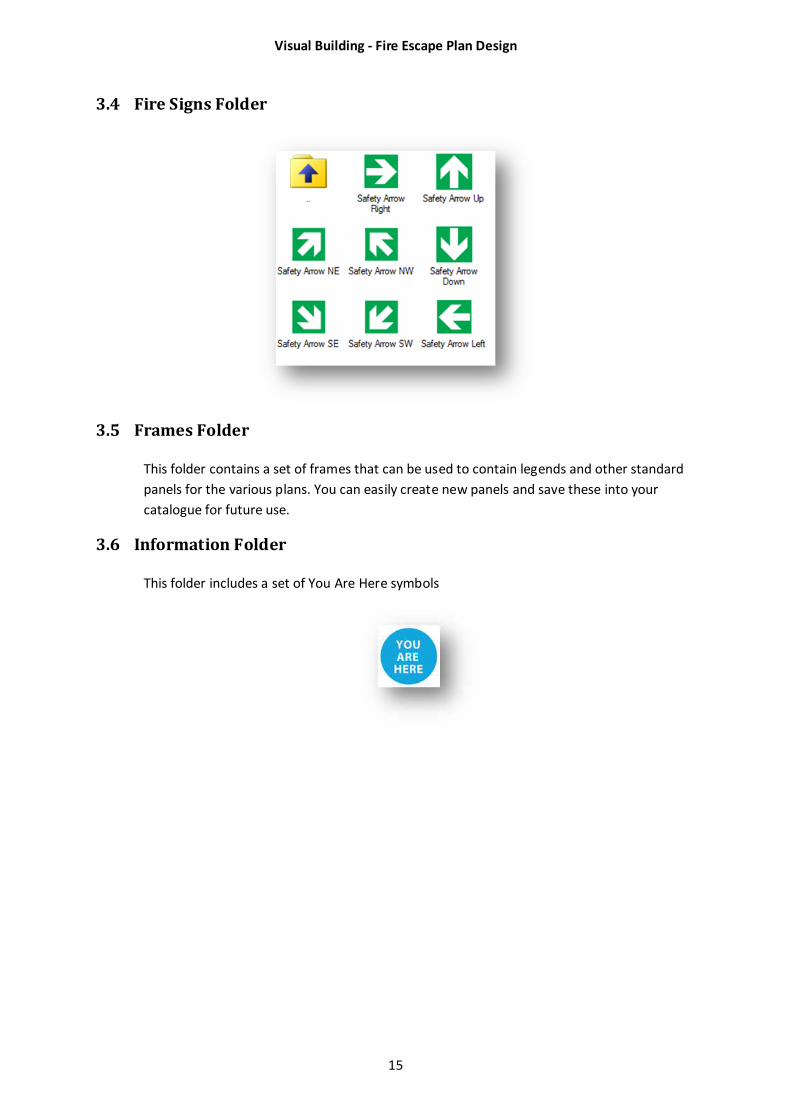
3.4 Fire Signs Folder
3.5 Frames Folder
This folder contains a set of frames that can be used to contain legends and other standard
panels for the various plans. You can easily create new panels and save these into your
catalogue for future use.
3.6 Information Folder
This folder includes a set of You Are Here symbols
Visual Building - Fire Escape Plan Design
16
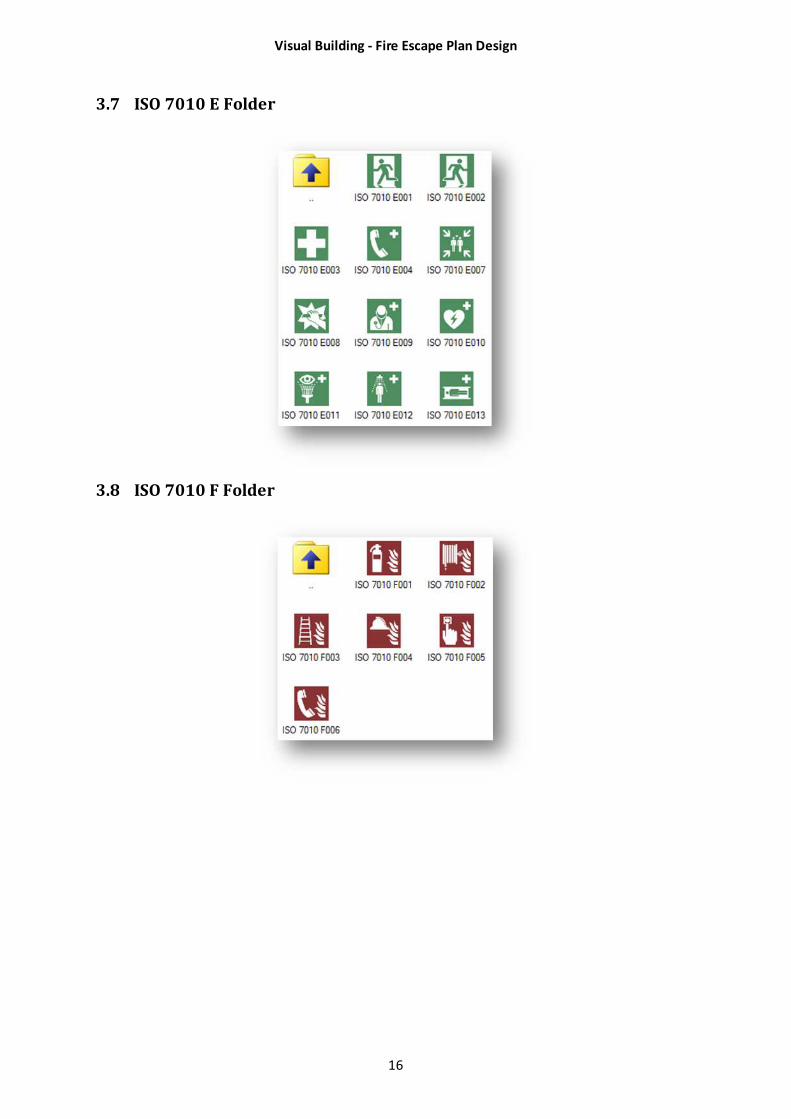
3.7 ISO 7010 E Folder
3.8 ISO 7010 F Folder
Visual Building - Fire Escape Plan Design
17
4 Overview
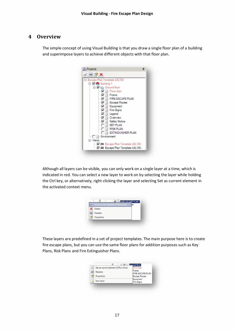
The simple concept of using Visual Building is that you draw a single floor plan of a building
and superimpose layers to achieve different objects with that floor plan.
Although all layers can be visible, you can only work on a single layer at a time, which is
indicated in red. You can select a new layer to work on by selecting the layer while holding
the Ctrl key, or alternatively, right clicking the layer and selecting Set as current element in
the activated context menu.
These layers are predefined in a set of project templates. The main purpose here is to create
fire escape plans, but you can use the same floor plans for addition purposes such as Key
Plans, Risk Plans and Fire Extinguisher Plans.
Visual Building - Fire Escape Plan Design
18
You are also able to add any additional layer at any time without interfering with existing
layers. To add a new layer, simply right click on the floor name, in the above example this
would be Ground floor, and select New layer.
4.1 Layers
The templates include the following layers:
4.1.1 Floor plan
This layer is where you draw the building’s walls. The wall thickness on the final printed plan
should not be less than the following:
Minimum structural wall thickness: 1.6 mm
Minimum partition wall thickness: 0.6 mm
Minimum line thickness for details such as stairs and windows: 0.15 mm
To achieve this minimum thickness the actual wall sizes used in your project will vary
depending upon the scale and paper size.
Note that all walls in your floor plan should be solid black lines. Cavity walls and hatched
walls should not be used. The wall thickness used does not have to be a true representation
of actual wall thickness, but there is a minimum requirement that must be displayed on an
escape plan:
Scale Type Line Wall Thickness
1:100 Structural 1.6 mm 160 mm
Partition 0.6mm 60 mm
1:250 Structural 1.6 mm 400 mm
Partition 0.6mm 150 mm
1:350 Structural 1.6 mm 560 mm
Partition 0.6mm 210 mm
We suggest that you use only the External wall and Supporting wall definitions to maintain
clarity of your plan. Note that these are the minimum lines / wall sizes which you can
increase depending upon the complexity of your plan.
Normally you use the same floor plan for all your requirements, but it is essential that you
use the above minimum line thickness for the purpose of Escape plans.
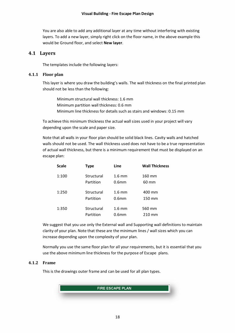
4.1.2 Frame
This is the drawings outer frame and can be used for all plan types.
Visual Building - Fire Escape Plan Design
19
4.1.3 Fire Escape Plan
The Escape Plan must have a standard header title: Escape plan. The header colour is in
safety green and must not be less than 7% of the height of the printed plan height. The title
text is white and must be at least 60% of the height of the header. The size of the title
header therefore relates to the height of the final printed sheet and so has the following
minimum settings:
Plan Size Size (mm) Header Height Text Height
(mm) (mm)
A3 297 x 420 21 12
A2 420 x 594 30 18
A1 594 x 841 42 26
A0 841 X 1189 59 36
Text
The minimal text height is 2mm and must be in black. Highlighted text can be in another
colour.
Colours
The background colour of the Escape plan shall be white.
Safety Symbols
All safety symbol signs must have a minimum height of 7mm
Plan Information
This must show the following information:
Designer of plan
Facility name
Floor
Date and revision of plan
Plan reference number
4.1.3.1 Escape Routes
Escape routes are highlighted in light green. Directional arrows are in safety green which
gives a good contrast upon the light green. The escape routes and directional arrows are
placed in the Escape Route layer. You can hide the escape route layer when using the Escape
Plan floor plan for other purposes.
4.1.3.2 Equipment Layer
This is a plan of all fire fighting equipment as found in the ISO 7010 F symbol catalogue.
4.1.3.3 Fire Signs Layer
This layer displays the green safety signs as found in the ISO 7010 E symbol catalogue.
Visual Building - Fire Escape Plan Design
20
4.1.3.4 Legend Layer
All escape plans must show a legend explaining the meaning of safety signs, graphical
symbols and colour coding used on the plan.
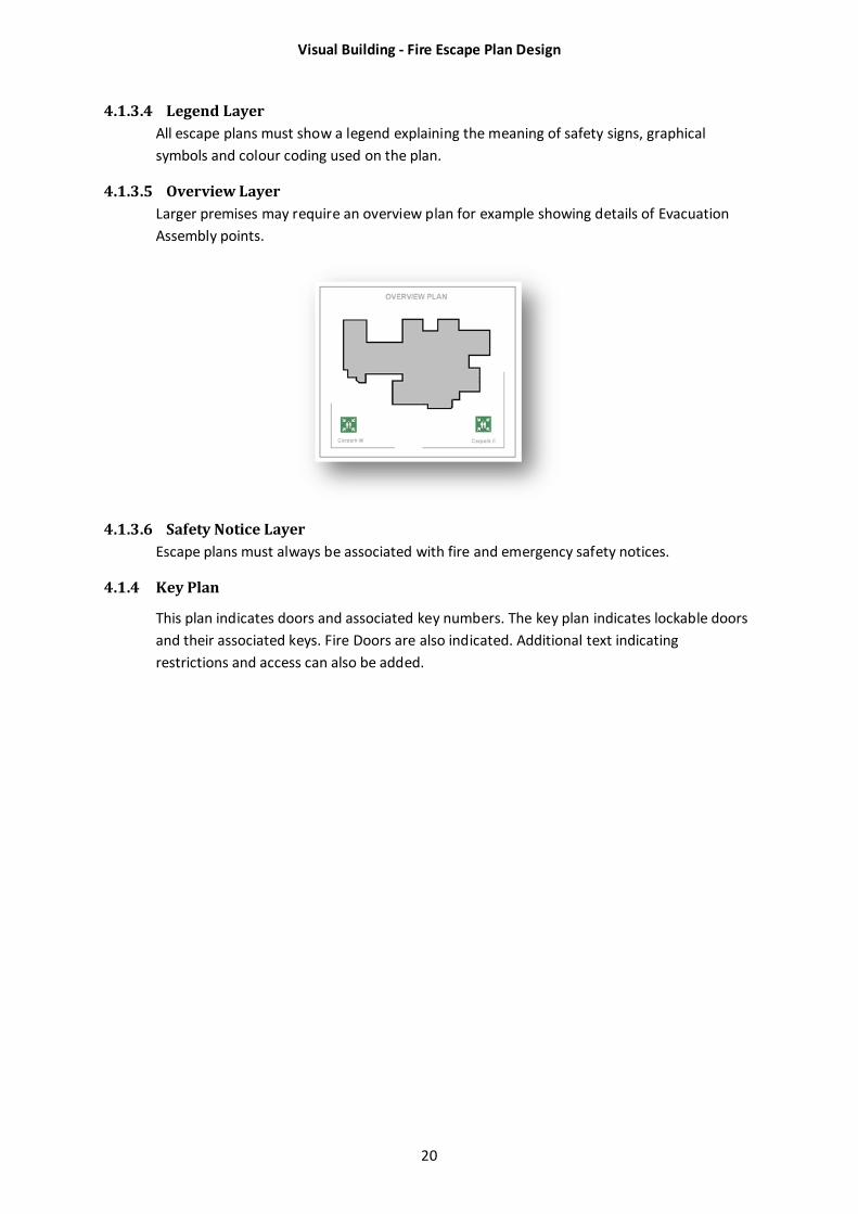
4.1.3.5 Overview Layer
Larger premises may require an overview plan for example showing details of Evacuation
Assembly points.
4.1.3.6 Safety Notice Layer
Escape plans must always be associated with fire and emergency safety notices.
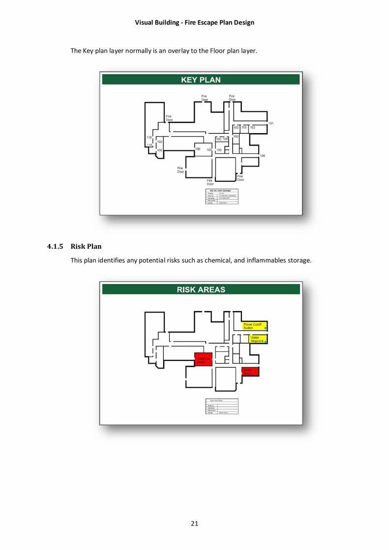
4.1.4 Key Plan
This plan indicates doors and associated key numbers. The key plan indicates lockable doors
and their associated keys. Fire Doors are also indicated. Additional text indicating
restrictions and access can also be added.
Visual Building - Fire Escape Plan Design
21
The Key plan layer normally is an overlay to the Floor plan layer.
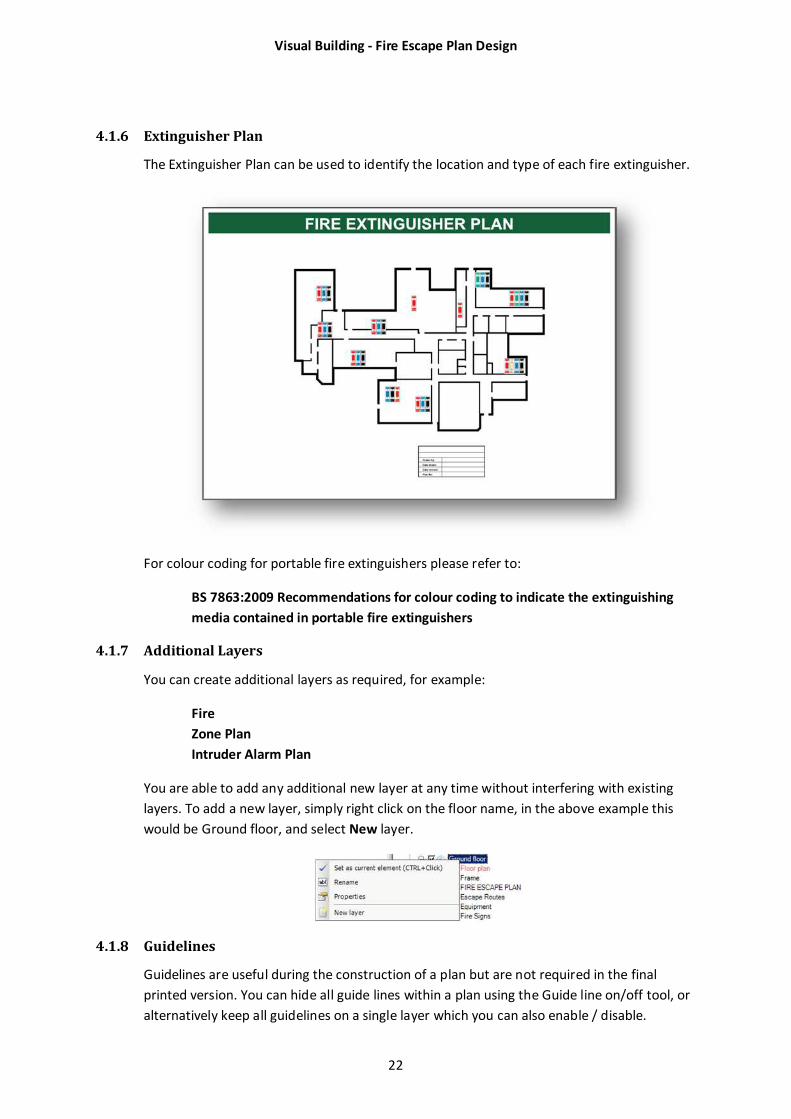
4.1.5 Risk Plan
This plan identifies any potential risks such as chemical, and inflammables storage.
Visual Building - Fire Escape Plan Design
22
4.1.6 Extinguisher Plan
The Extinguisher Plan can be used to identify the location and type of each fire extinguisher.
For colour coding for portable fire extinguishers please refer to:
BS 7863:2009 Recommendations for colour coding to indicate the extinguishing
media contained in portable fire extinguishers
4.1.7 Additional Layers
You can create additional layers as required, for example:
Fire
Zone Plan
Intruder Alarm Plan
You are able to add any additional new layer at any time without interfering with existing
layers. To add a new layer, simply right click on the floor name, in the above example this
would be Ground floor, and select New layer.
4.1.8 Guidelines
Guidelines are useful during the construction of a plan but are not required in the final
printed version. You can hide all guide lines within a plan using the Guide line on/off tool, or
alternatively keep all guidelines on a single layer which you can also enable / disable.

Visual Building - Fire Escape Plan Design
23
To help you highlight the guidelines, we suggest you set your guideline colour to blue and
line style to solid.
Visual Building - Fire Escape Plan Design
24
5 Create a Fire Escape Plan
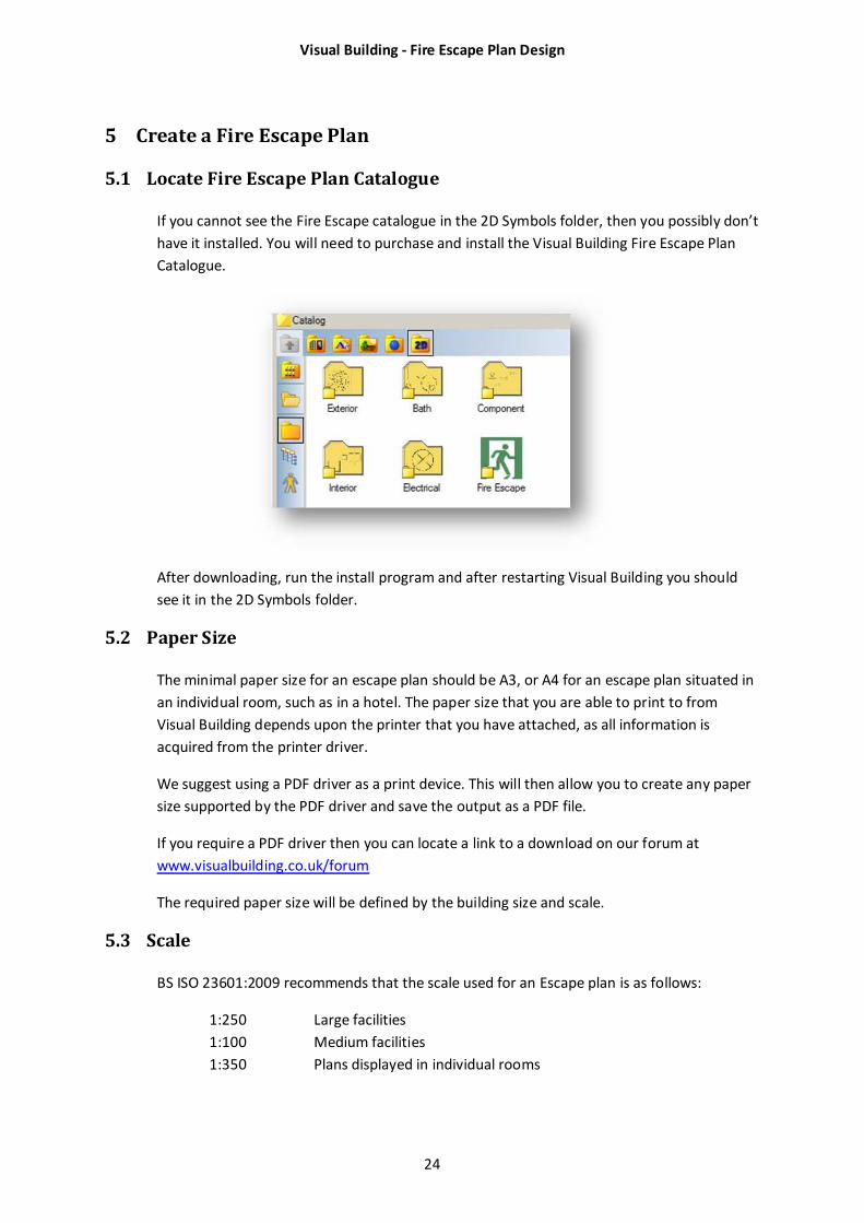
5.1 Locate Fire Escape Plan Catalogue
If you cannot see the Fire Escape catalogue in the 2D Symbols folder, then you possibly don’t
have it installed. You will need to purchase and install the Visual Building Fire Escape Plan
Catalogue.
After downloading, run the install program and after restarting Visual Building you should
see it in the 2D Symbols folder.
5.2 Paper Size
The minimal paper size for an escape plan should be A3, or A4 for an escape plan situated in
an individual room, such as in a hotel. The paper size that you are able to print to from
Visual Building depends upon the printer that you have attached, as all information is
acquired from the printer driver.
We suggest using a PDF driver as a print device. This will then allow you to create any paper
size supported by the PDF driver and save the output as a PDF file.
If you require a PDF driver then you can locate a link to a download on our forum at
www.visualbuilding.co.uk/forum
The required paper size will be defined by the building size and scale.
5.3 Scale
BS ISO 23601:2009 recommends that the scale used for an Escape plan is as follows:
1:250 Large facilities
1:100 Medium facilities
1:350 Plans displayed in individual rooms
Visual Building - Fire Escape Plan Design
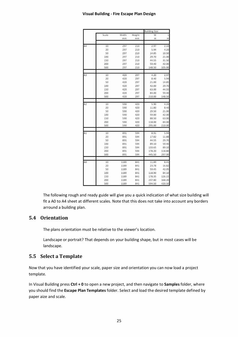
25
The following rough and ready guide will give you a quick indication of what size building will
fit a A0 to A4 sheet at different scales. Note that this does not take into account any borders
arround a building plan.
5.4 Orientation
The plans orientation must be relative to the viewer’s location.
Landscape or portrait? That depends on your building shape, but in most cases will be
landscape.
5.5 Select a Template
Now that you have identified your scale, paper size and orientation you can now load a project
template.
In Visual Building press Ctrl + 0 to open a new project, and then navigate to Samples folder, where
you should find the Escape Plan Templates folder. Select and load the desired template defined by
paper aize and scale.
Visual Building - Fire Escape Plan Design
26
Template name Size Orientation Scale
EscapePlanTemplateA4L100 A4 Landscape 1:100
EscapePlanTemplateA4L250 A4 Landscape 1:250
EscapePlanTemplateA4L350 A4 Landscape 1:350
EscapePlanTemplateA4P100 A4 Portrait 1:100
EscapeplanTemplateA3L100 A3 Landscape 1:100
EscapeplanTemplateA3P100 A3 Portrait 1:100
Our example will be based on a building 25m x 16m, plus a car park. This is a medium sized building
and so we should draw this at a scale of 1:100. Although it would fit on an A4 sheet which would
allow for a building 29.7 m x 21, there would not be sufficient space for legends, assembly point
diagram and safety notices, so we will choose an A3 sheet Landscape at a scale of 1:100.
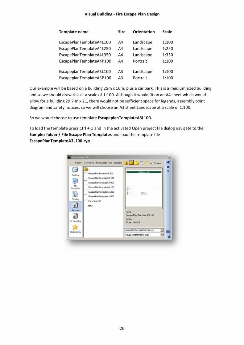
So we would choose to use template EscapeplanTemplateA3L100.
To load the template press Ctrl + O and in the activated Open project file dialog navigate to the
Samples folder / File Escape Plan Templates and load the template file
EscapePlanTemplateA3L100.cyp
Visual Building - Fire Escape Plan Design
27
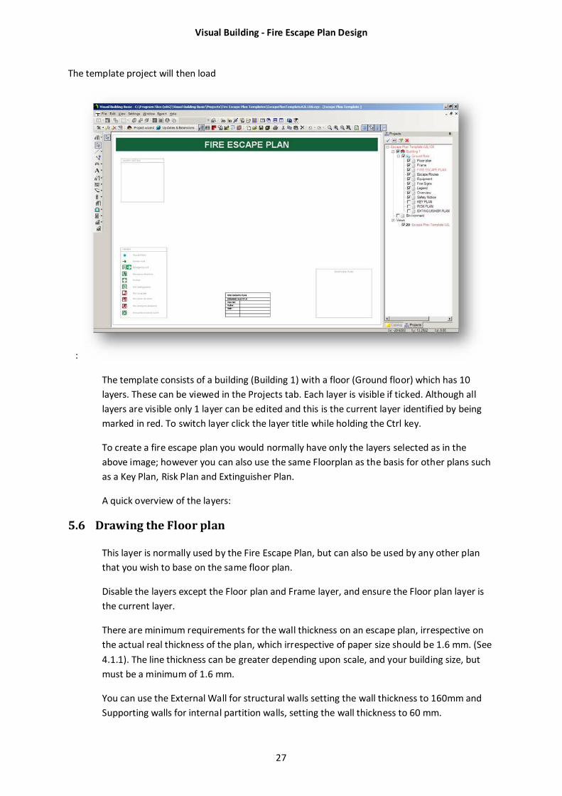
The template project will then load
:
The template consists of a building (Building 1) with a floor (Ground floor) which has 10
layers. These can be viewed in the Projects tab. Each layer is visible if ticked. Although all
layers are visible only 1 layer can be edited and this is the current layer identified by being
marked in red. To switch layer click the layer title while holding the Ctrl key.
To create a fire escape plan you would normally have only the layers selected as in the
above image; however you can also use the same Floorplan as the basis for other plans such
as a Key Plan, Risk Plan and Extinguisher Plan.
A quick overview of the layers:
5.6 Drawing the Floor plan
This layer is normally used by the Fire Escape Plan, but can also be used by any other plan
that you wish to base on the same floor plan.
Disable the layers except the Floor plan and Frame layer, and ensure the Floor plan layer is
the current layer.
There are minimum requirements for the wall thickness on an escape plan, irrespective on
the actual real thickness of the plan, which irrespective of paper size should be 1.6 mm. (See
4.1.1). The line thickness can be greater depending upon scale, and your building size, but
must be a minimum of 1.6 mm.
You can use the External Wall for structural walls setting the wall thickness to 160mm and
Supporting walls for internal partition walls, setting the wall thickness to 60 mm.
Visual Building - Fire Escape Plan Design
28
5.6.1 Setting wall thickness
To set the wall thickness
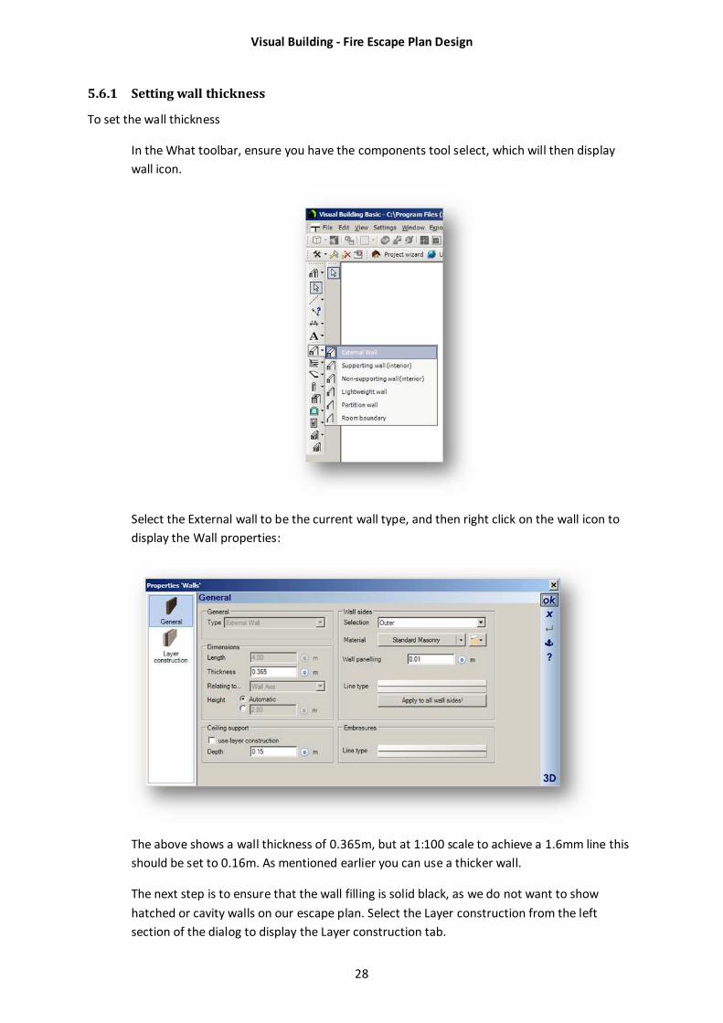
In the What toolbar, ensure you have the components tool select, which will then display
wall icon.
Select the External wall to be the current wall type, and then right click on the wall icon to
display the Wall properties:
The above shows a wall thickness of 0.365m, but at 1:100 scale to achieve a 1.6mm line this
should be set to 0.16m. As mentioned earlier you can use a thicker wall.
The next step is to ensure that the wall filling is solid black, as we do not want to show
hatched or cavity walls on our escape plan. Select the Layer construction from the left
section of the dialog to display the Layer construction tab.
Visual Building - Fire Escape Plan Design
29
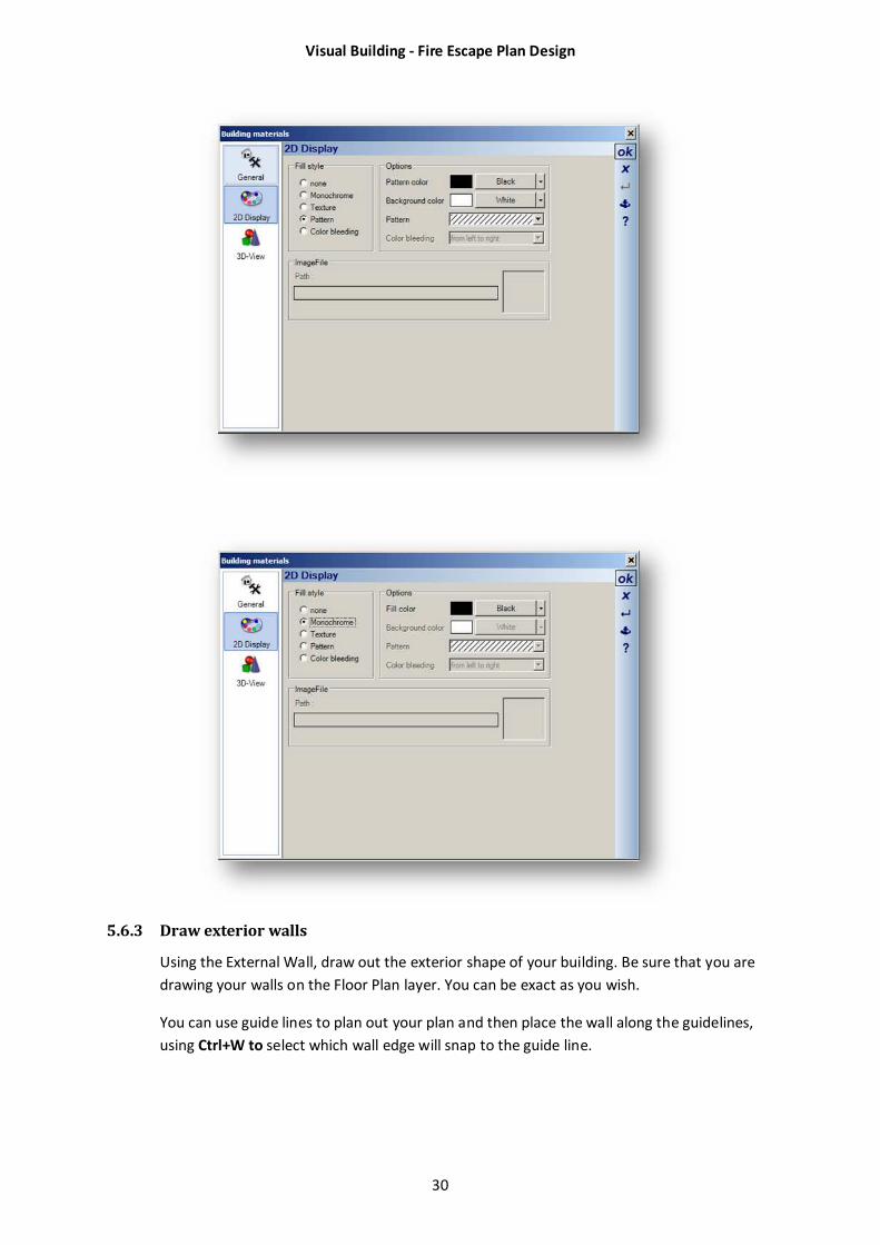
5.6.2 Setting wall colour
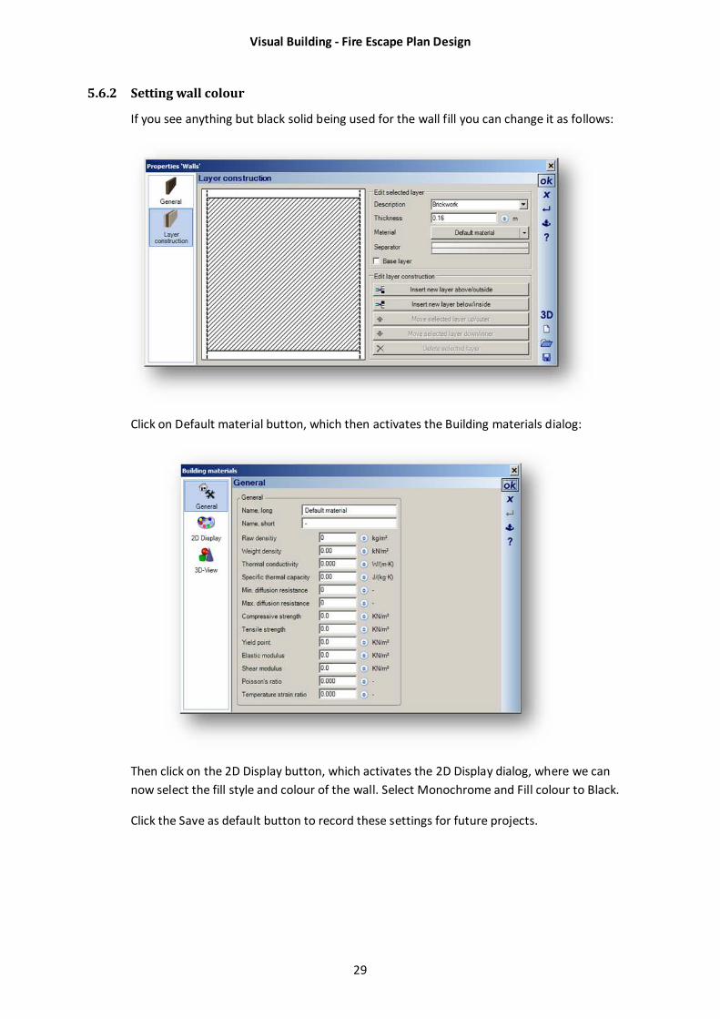
If you see anything but black solid being used for the wall fill you can change it as follows:
Click on Default material button, which then activates the Building materials dialog:
Then click on the 2D Display button, which activates the 2D Display dialog, where we can
now select the fill style and colour of the wall. Select Monochrome and Fill colour to Black.
Click the Save as default button to record these settings for future projects.
Visual Building - Fire Escape Plan Design
30
5.6.3 Draw exterior walls
Using the External Wall, draw out the exterior shape of your building. Be sure that you are
drawing your walls on the Floor Plan layer. You can be exact as you wish.
You can use guide lines to plan out your plan and then place the wall along the guidelines,
using Ctrl+W to select which wall edge will snap to the guide line.
Visual Building - Fire Escape Plan Design
31
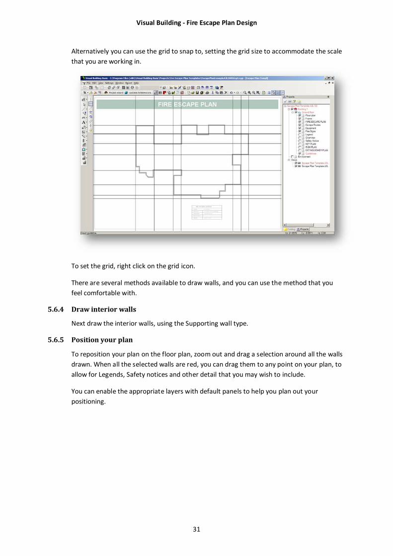
Alternatively you can use the grid to snap to, setting the grid size to accommodate the scale
that you are working in.
To set the grid, right click on the grid icon.
There are several methods available to draw walls, and you can use the method that you
feel comfortable with.
5.6.4 Draw interior walls
Next draw the interior walls, using the Supporting wall type.
5.6.5 Position your plan
To reposition your plan on the floor plan, zoom out and drag a selection around all the walls
drawn. When all the selected walls are red, you can drag them to any point on your plan, to
allow for Legends, Safety notices and other detail that you may wish to include.
You can enable the appropriate layers with default panels to help you plan out your
positioning.
Visual Building - Fire Escape Plan Design
32
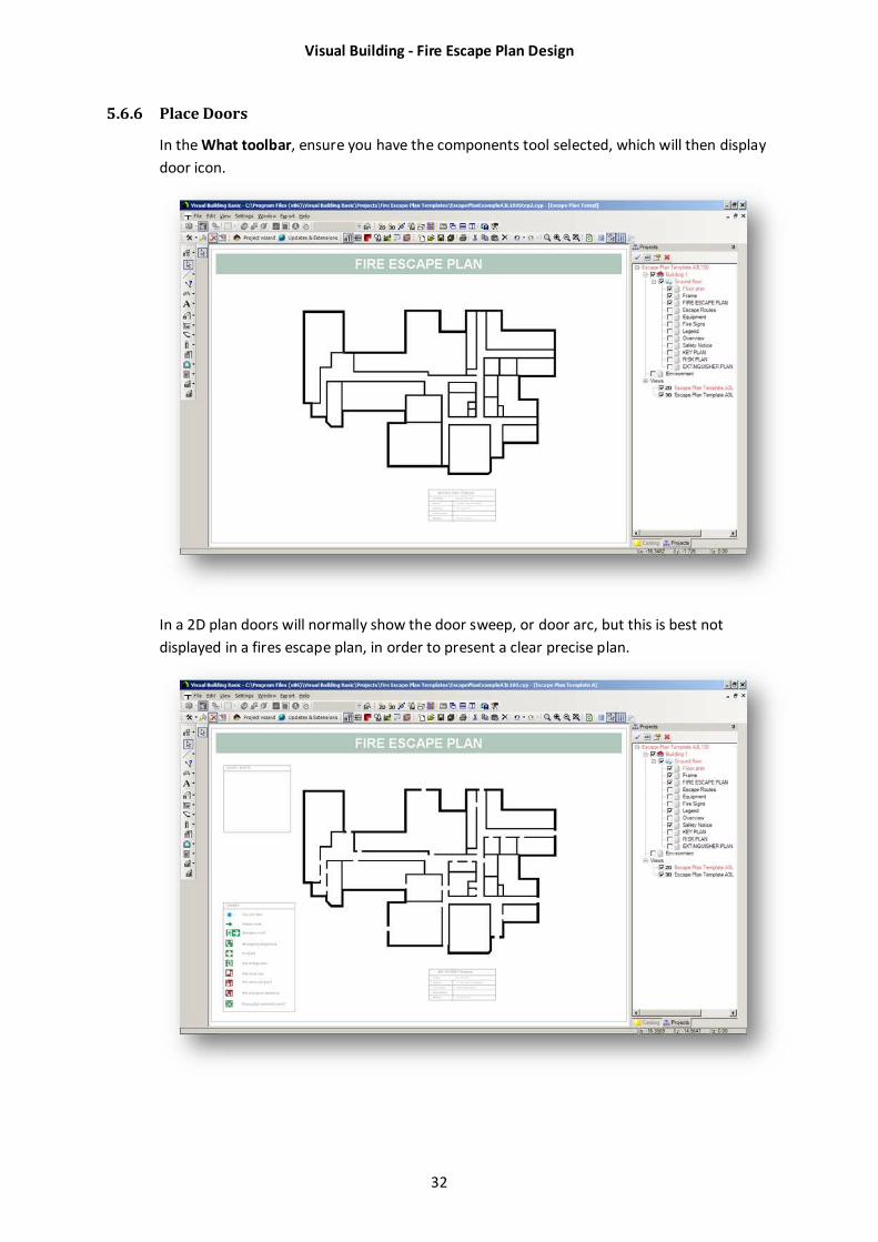
5.6.6 Place Doors
In the What toolbar, ensure you have the components tool selected, which will then display
door icon.
In a 2D plan doors will normally show the door sweep, or door arc, but this is best not
displayed in a fires escape plan, in order to present a clear precise plan.
Visual Building - Fire Escape Plan Design
33
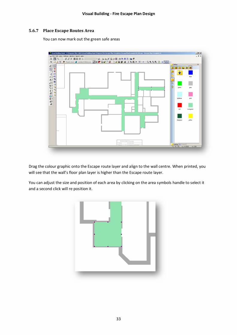
5.6.7 Place Escape Routes Area
You can now mark out the green safe areas
Drag the colour graphic onto the Escape route layer and align to the wall centre. When printed, you
will see that the wall’s floor plan layer is higher than the Escape route layer.
You can adjust the size and position of each area by clicking on the area symbols handle to select it
and a second click will re position it.
Visual Building - Fire Escape Plan Design
34
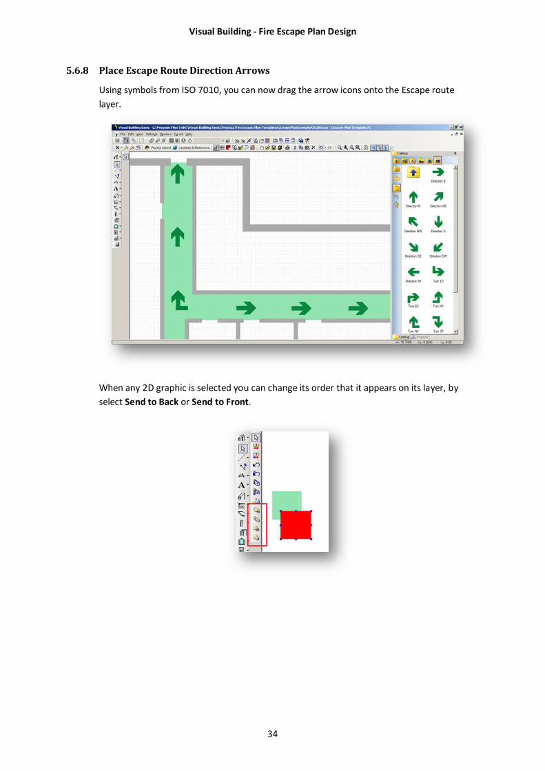
5.6.8 Place Escape Route Direction Arrows
Using symbols from ISO 7010, you can now drag the arrow icons onto the Escape route
layer.
When any 2D graphic is selected you can change its order that it appears on its layer, by
select Send to Back or Send to Front.
Visual Building - Fire Escape Plan Design
35
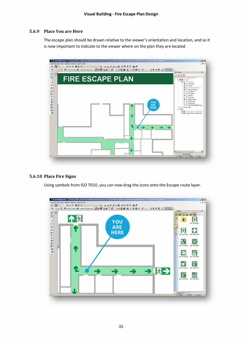
5.6.9 Place You are Here
The escape plan should be drawn relative to the viewer’s orientation and location, and so it
is now important to indicate to the viewer where on the plan they are located
5.6.10 Place Fire Signs
Using symbols from ISO 7010, you can now drag the icons onto the Escape route layer.
Visual Building - Fire Escape Plan Design
36
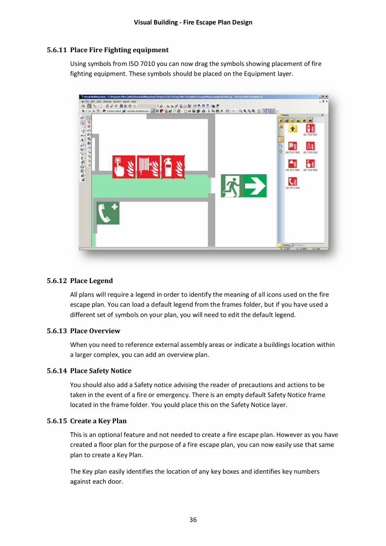
5.6.11 Place Fire Fighting equipment
Using symbols from ISO 7010 you can now drag the symbols showing placement of fire
fighting equipment. These symbols should be placed on the Equipment layer.
5.6.12 Place Legend
All plans will require a legend in order to identify the meaning of all icons used on the fire
escape plan. You can load a default legend from the frames folder, but if you have used a
different set of symbols on your plan, you will need to edit the default legend.
5.6.13 Place Overview
When you need to reference external assembly areas or indicate a buildings location within
a larger complex, you can add an overview plan.
5.6.14 Place Safety Notice
You should also add a Safety notice advising the reader of precautions and actions to be
taken in the event of a fire or emergency. There is an empty default Safety Notice frame
located in the frame folder. You yould place this on the Safety Notice layer.
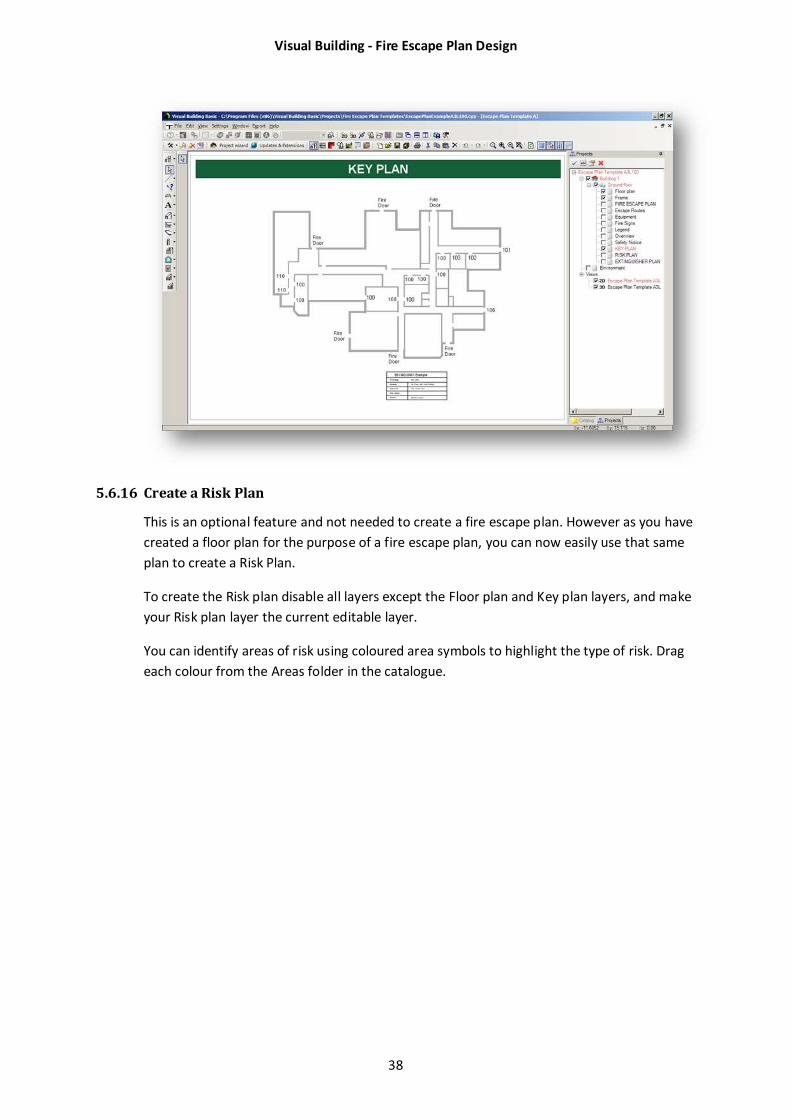
5.6.15 Create a Key Plan
This is an optional feature and not needed to create a fire escape plan. However as you have
created a floor plan for the purpose of a fire escape plan, you can now easily use that same
plan to create a Key Plan.
The Key plan easily identifies the location of any key boxes and identifies key numbers
against each door.
Visual Building - Fire Escape Plan Design
37
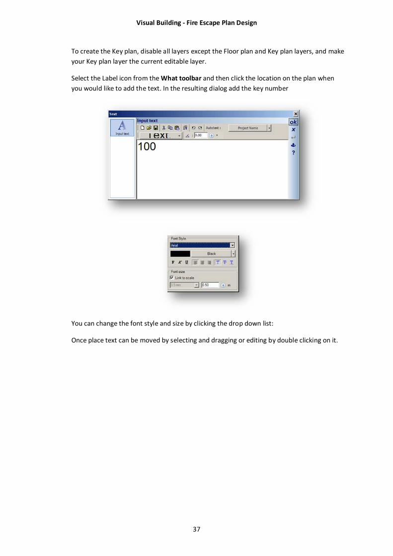
To create the Key plan, disable all layers except the Floor plan and Key plan layers, and make
your Key plan layer the current editable layer.
Select the Label icon from the What toolbar and then click the location on the plan when
you would like to add the text. In the resulting dialog add the key number
You can change the font style and size by clicking the drop down list:
Once place text can be moved by selecting and dragging or editing by double clicking on it.
Visual Building - Fire Escape Plan Design
38
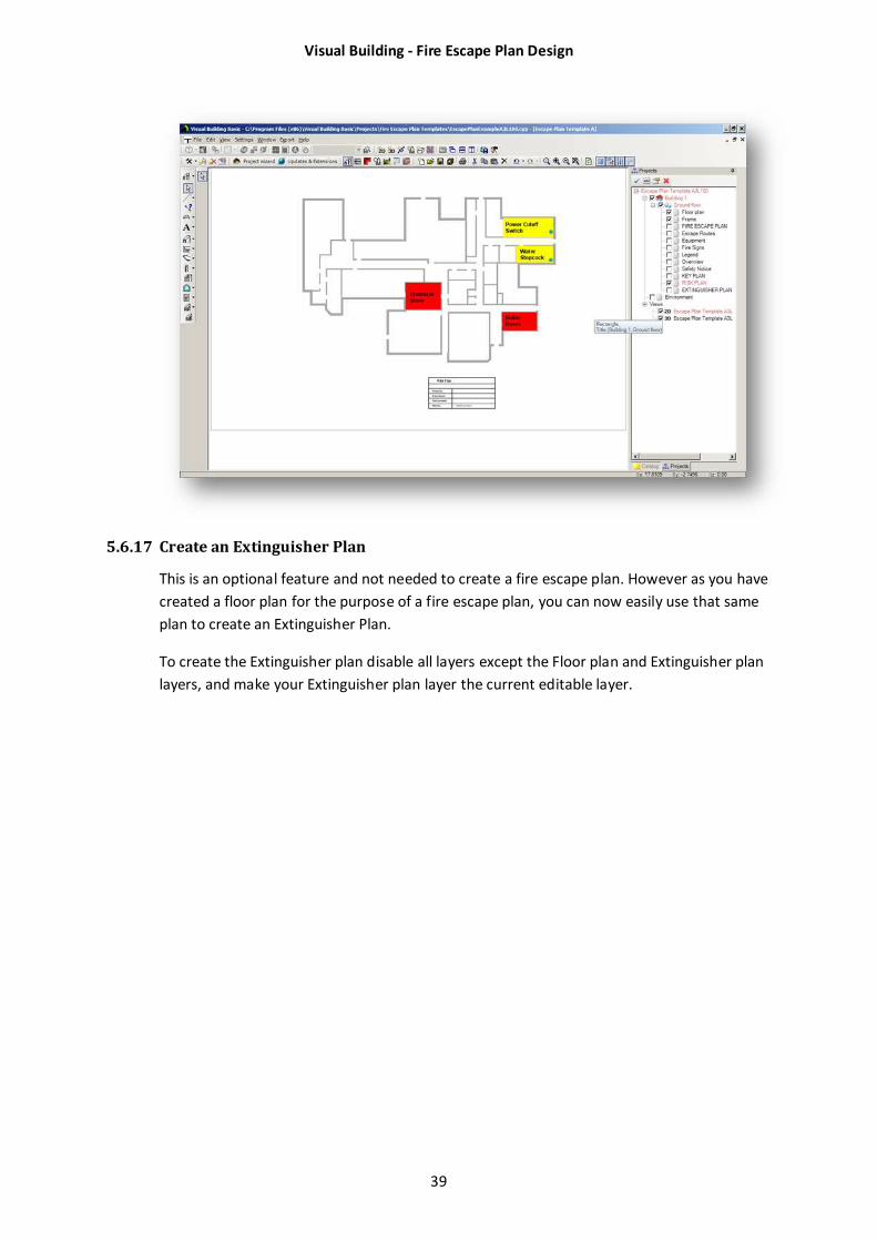
5.6.16 Create a Risk Plan
This is an optional feature and not needed to create a fire escape plan. However as you have
created a floor plan for the purpose of a fire escape plan, you can now easily use that same
plan to create a Risk Plan.
To create the Risk plan disable all layers except the Floor plan and Key plan layers, and make
your Risk plan layer the current editable layer.
You can identify areas of risk using coloured area symbols to highlight the type of risk. Drag
each colour from the Areas folder in the catalogue.
Visual Building - Fire Escape Plan Design
39
5.6.17 Create an Extinguisher Plan
This is an optional feature and not needed to create a fire escape plan. However as you have
created a floor plan for the purpose of a fire escape plan, you can now easily use that same
plan to create an Extinguisher Plan.
To create the Extinguisher plan disable all layers except the Floor plan and Extinguisher plan
layers, and make your Extinguisher plan layer the current editable layer.

Visual Building - Fire Escape Plan Design
40
6 Printing
Printers vary as how far to the edge of a sheet they can print and this is indicated by the size
of the print area displayed when you print. We recommend that you print to a pdf file first,
mainly because it’s quicker and saves paper. When you have achieved what you want on the
pdf file you can then print the pdf file to a printer. This can save a lot of time, a lot of paper
and a lot of trees.
Visual Building - Fire Escape Plan Design
41
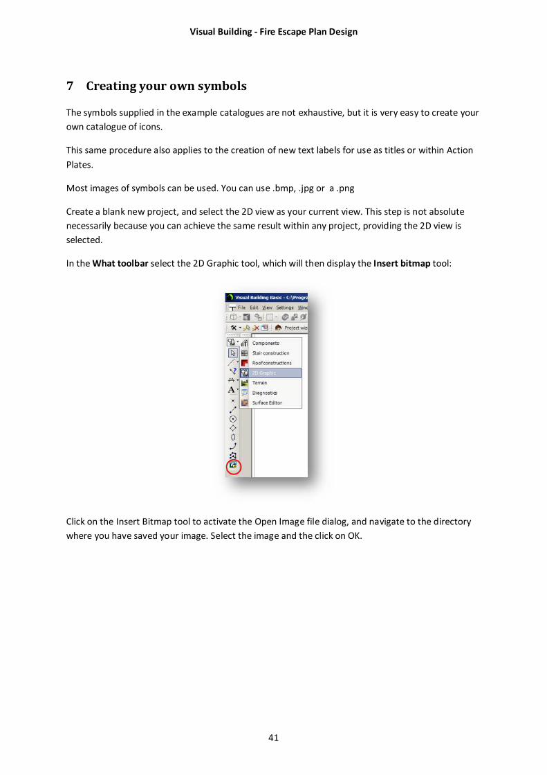
7 Creating your own symbols
The symbols supplied in the example catalogues are not exhaustive, but it is very easy to create your
own catalogue of icons.
This same procedure also applies to the creation of new text labels for use as titles or within Action
Plates.
Most images of symbols can be used. You can use .bmp, .jpg or a .png
Create a blank new project, and select the 2D view as your current view. This step is not absolute
necessarily because you can achieve the same result within any project, providing the 2D view is
selected.
In the What toolbar select the 2D Graphic tool, which will then display the Insert bitmap tool:
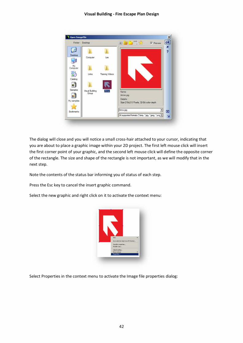
Click on the Insert Bitmap tool to activate the Open Image file dialog, and navigate to the directory
where you have saved your image. Select the image and the click on OK.
Visual Building - Fire Escape Plan Design
42
The dialog will close and you will notice a small cross-hair attached to your cursor, indicating that
you are about to place a graphic image within your 2D project. The first left mouse click will insert
the first corner point of your graphic, and the second left mouse click will define the opposite corner
of the rectangle. The size and shape of the rectangle is not important, as we will modify that in the
next step.
Note the contents of the status bar informing you of status of each step.
Press the Esc key to cancel the insert graphic command.
Select the new graphic and right click on it to activate the context menu:
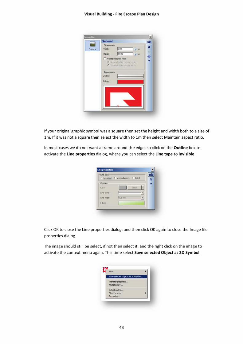
Select Properties in the context menu to activate the Image file properties dialog:
Visual Building - Fire Escape Plan Design
43
If your original graphic symbol was a square then set the height and width both to a size of
1m. If it was not a square then select the width to 1m then select Maintain aspect ratio.
In most cases we do not want a frame around the edge, so click on the Outline box to
activate the Line properties dialog, where you can select the Line type to invisible.
Click OK to close the Line properties dialog, and then click OK again to close the Image file
properties dialog.
The image should still be select, if not then select it, and the right click on the image to
activate the context menu again. This time select Save selected Object as 2D Symbol.
Visual Building - Fire Escape Plan Design
44
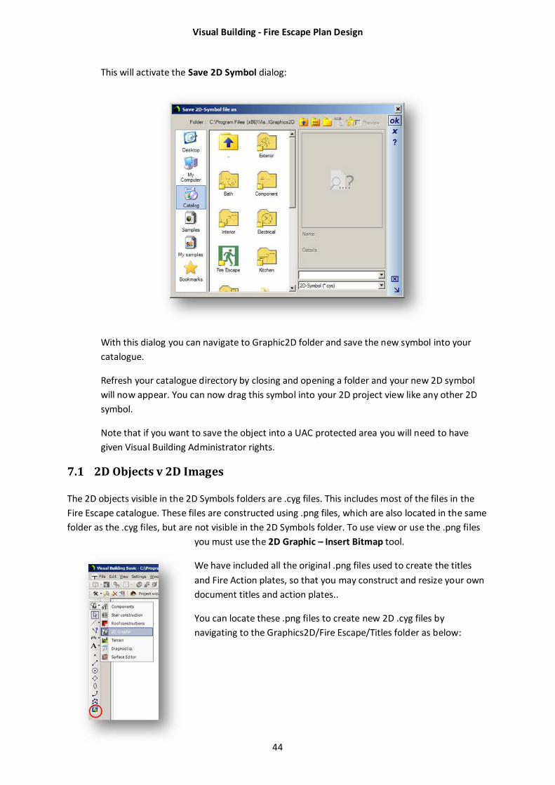
This will activate the Save 2D Symbol dialog:
With this dialog you can navigate to Graphic2D folder and save the new symbol into your
catalogue.
Refresh your catalogue directory by closing and opening a folder and your new 2D symbol
will now appear. You can now drag this symbol into your 2D project view like any other 2D
symbol.
Note that if you want to save the object into a UAC protected area you will need to have
given Visual Building Administrator rights.
7.1 2D Objects v 2D Images
The 2D objects visible in the 2D Symbols folders are .cyg files. This includes most of the files in the
Fire Escape catalogue. These files are constructed using .png files, which are also located in the same
folder as the .cyg files, but are not visible in the 2D Symbols folder. To use view or use the .png files
you must use the 2D Graphic – Insert Bitmap tool.
We have included all the original .png files used to create the titles
and Fire Action plates, so that you may construct and resize your own
document titles and action plates..
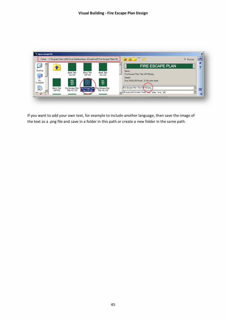
You can locate these .png files to create new 2D .cyg files by
navigating to the Graphics2D/Fire Escape/Titles folder as below:
Visual Building - Fire Escape Plan Design
45
If you want to add your own text, for example to include another language, then save the image of
the text as a .png file and save in a folder in this path or create a new folder in the same path.
Visual Building - Fire Escape Plan Design
46
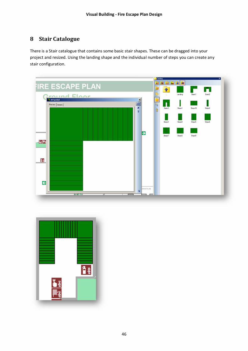
8 Stair Catalogue
There is a Stair catalogue that contains some basic stair shapes. These can be dragged into your
project and resized. Using the landing shape and the individual number of steps you can create any
stair configuration.
Visual Building - Fire Escape Plan Design
47
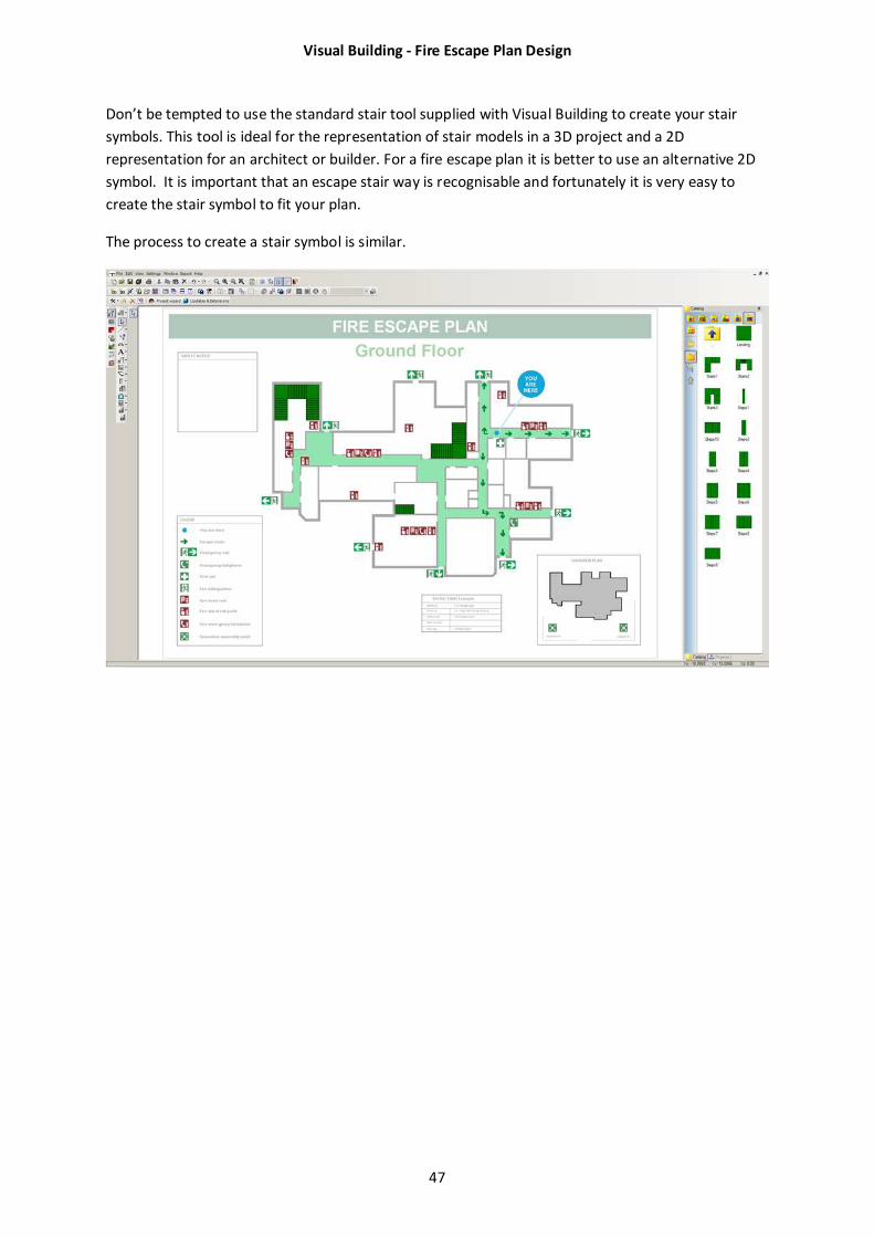
Don’t be tempted to use the standard stair tool supplied with Visual Building to create your stair
symbols. This tool is ideal for the representation of stair models in a 3D project and a 2D
representation for an architect or builder. For a fire escape plan it is better to use an alternative 2D
symbol. It is important that an escape stair way is recognisable and fortunately it is very easy to
create the stair symbol to fit your plan.
The process to create a stair symbol is similar.
Visual Building - Fire Escape Plan Design
48
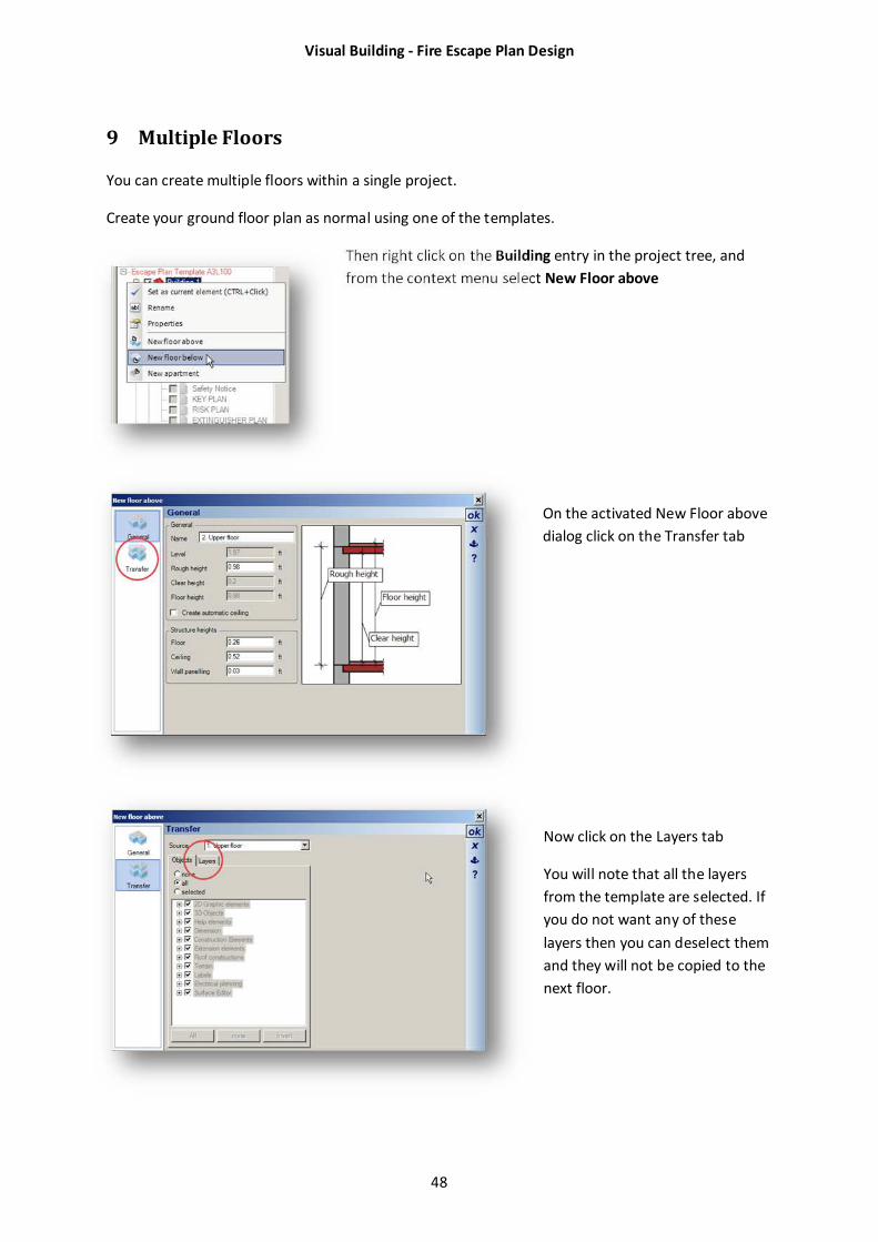
9 Multiple Floors
You can create multiple floors within a single project.
Create your ground floor plan as normal using one of the templates.
Then right click on the Building entry in the project tree, and
from the context menu select New Floor above
On the activated New Floor above
dialog click on the Transfer tab
Now click on the Layers tab
You will note that all the layers
from the template are selected. If
you do not want any of these
layers then you can deselect them
and they will not be copied to the
next floor.
Visual Building - Fire Escape Plan Design
49
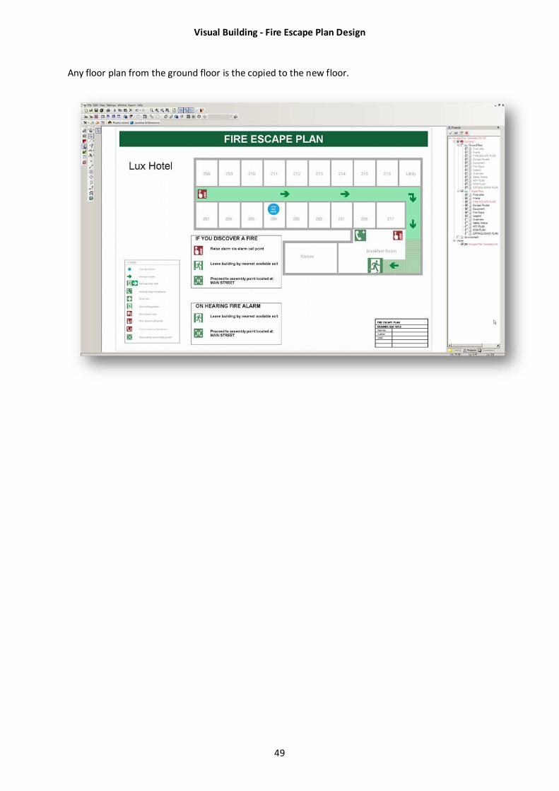
Any floor plan from the ground floor is the copied to the new floor.
Visual Building - Fire Escape Plan Design
50
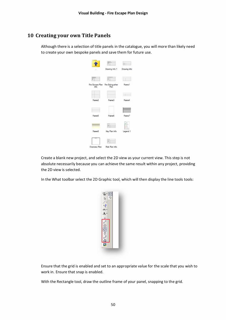
10 Creating your own Title Panels
Although there is a selection of title panels in the catalogue, you will more than likely need
to create your own bespoke panels and save them for future use.
Create a blank new project, and select the 2D view as your current view. This step is not
absolute necessarily because you can achieve the same result within any project, providing
the 2D view is selected.
In the What toolbar select the 2D Graphic tool, which will then display the line tools tools:
Ensure that the grid is enabled and set to an appropriate value for the scale that you wish to
work in. Ensure that snap is enabled.
With the Rectangle tool, draw the outline frame of your panel, snapping to the grid.
Visual Building - Fire Escape Plan Design
51
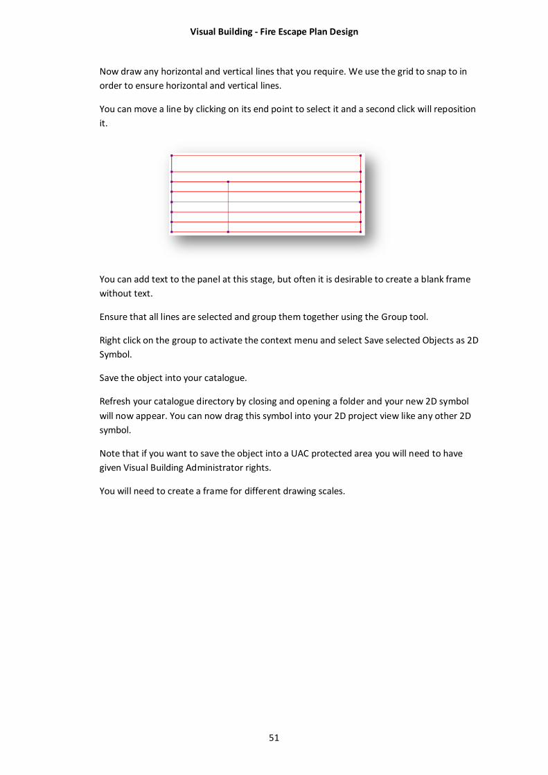
Now draw any horizontal and vertical lines that you require. We use the grid to snap to in
order to ensure horizontal and vertical lines.
You can move a line by clicking on its end point to select it and a second click will reposition
it.
You can add text to the panel at this stage, but often it is desirable to create a blank frame
without text.
Ensure that all lines are selected and group them together using the Group tool.
Right click on the group to activate the context menu and select Save selected Objects as 2D
Symbol.
Save the object into your catalogue.
Refresh your catalogue directory by closing and opening a folder and your new 2D symbol
will now appear. You can now drag this symbol into your 2D project view like any other 2D
symbol.
Note that if you want to save the object into a UAC protected area you will need to have
given Visual Building Administrator rights.
You will need to create a frame for different drawing scales.
Visual Building - Fire Escape Plan Design
52
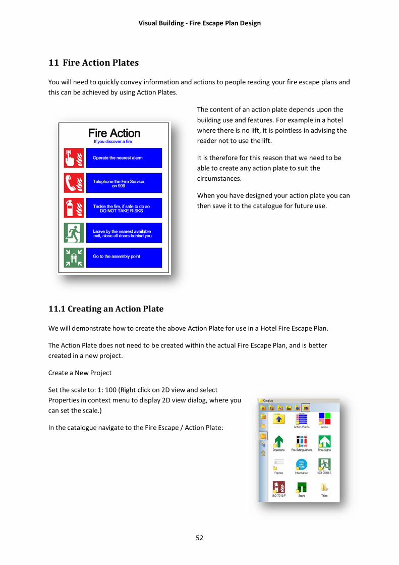
11 Fire Action Plates
You will need to quickly convey information and actions to people reading your fire escape plans and
this can be achieved by using Action Plates.
The content of an action plate depends upon the
building use and features. For example in a hotel
where there is no lift, it is pointless in advising the
reader not to use the lift.
It is therefore for this reason that we need to be
able to create any action plate to suit the
circumstances.
When you have designed your action plate you can
then save it to the catalogue for future use.
11.1 Creating an Action Plate
We will demonstrate how to create the above Action Plate for use in a Hotel Fire Escape Plan.
The Action Plate does not need to be created within the actual Fire Escape Plan, and is better
created in a new project.
Create a New Project
Set the scale to: 1: 100 (Right click on 2D view and select
Properties in context menu to display 2D view dialog, where you
can set the scale.)
In the catalogue navigate to the Fire Escape / Action Plate:
Visual Building - Fire Escape Plan Design
53
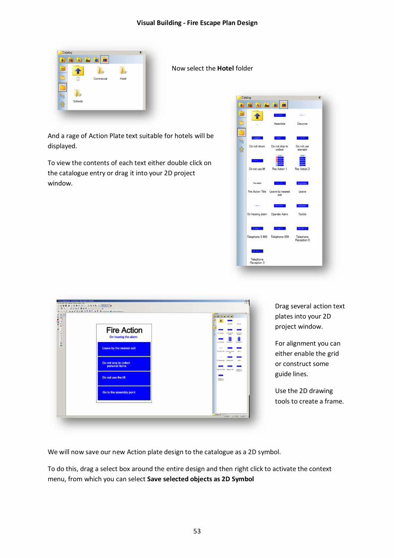
Now select the Hotel folder
And a rage of Action Plate text suitable for hotels will be
displayed.
To view the contents of each text either double click on
the catalogue entry or drag it into your 2D project
window.
Drag several action text
plates into your 2D
project window.
For alignment you can
either enable the grid
or construct some
guide lines.
Use the 2D drawing
tools to create a frame.
We will now save our new Action plate design to the catalogue as a 2D symbol.
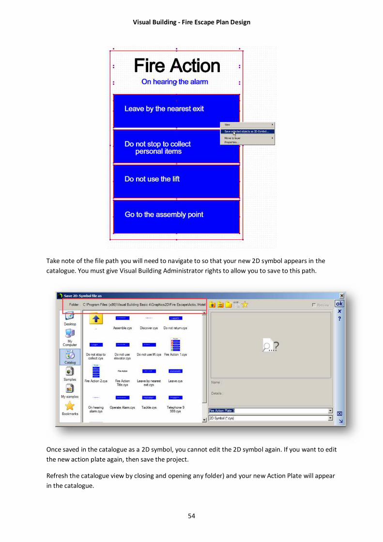
To do this, drag a select box around the entire design and then right click to activate the context
menu, from which you can select Save selected objects as 2D Symbol
Visual Building - Fire Escape Plan Design
54
Take note of the file path you will need to navigate to so that your new 2D symbol appears in the
catalogue. You must give Visual Building Administrator rights to allow you to save to this path.
Once saved in the catalogue as a 2D symbol, you cannot edit the 2D symbol again. If you want to edit
the new action plate again, then save the project.
Refresh the catalogue view by closing and opening any folder) and your new Action Plate will appear
in the catalogue.
Visual Building - Fire Escape Plan Design
55
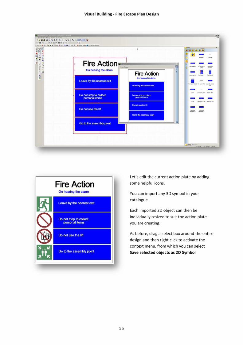
Let’s edit the current action plate by adding
some helpful icons.
You can import any 3D symbol in your
catalogue.
Each imported 2D object can then be
individually resized to suit the action plate
you are creating.
As before, drag a select box around the entire
design and then right click to activate the
context menu, from which you can select
Save selected objects as 2D Symbol

Visual Building - Fire Escape Plan Design
56
12 INDEMNITY
This document and associated software has been produced as a tool to assist you in
completing various floor plans associated with a fire safety risk assessment of your premises.
It is used entirely at your own risk to produce suitable plans, and also whether you consider
the information therein to be suitable and sufficient. It is in no way exhaustive and Visual
Building Ltd accepts no liability for any circumstances which may arise as a result of using
this tool.
Fire safety and fire prevention are very important matters, and you should always consult
with a qualified expert concerning the appropriate requirements and use of any safety
signs.