Embed Size (px)
Citation preview
800-11045 2/12 Rev. C
VISTA-32FBPT
Commercial Fire and BurglaryCommercial Fire and BurglaryCommercial Fire and BurglaryCommercial Fire and Burglary
Partitioned Security SystemsPartitioned Security SystemsPartitioned Security SystemsPartitioned Security Systems
with Schedulingwith Schedulingwith Schedulingwith Scheduling
User GuideUser GuideUser GuideUser Guide

– 2 –
– 3 –
TABLE OF CONTENTS
SYSTEM OVERVIEW ............................ 5 General ...................................................... 5 A Partitioned System ................................. 5 Zones ......................................................... 6 Fire Protection ............................................ 6 Burglary Protection .................................... 6 Carbon Monoxide Protection ..................... 7 Alarms ........................................................ 7 Memory of Alarm ........................................ 7 Using Schedules ........................................ 7 Device Timers ............................................ 8 To Access another Partition (GOTO Command) ................................................. 8 Master Keypad Operation .......................... 8 Self-Help Feature ....................................... 9
ABOUT THE KEYPADS ....................... 10 General .................................................... 10 The Alpha Keypad ................................... 10
FUNCTIONS OF THE KEYPAD ........... 11 ENTRY/EXIT DELAYS ......................... 15
General Information ................................. 15 SECURITY CODES AND
AUTHORITY LEVELS ....................... 16 General Information ................................. 16 Duress Code ............................................ 16 Quick Arming............................................ 16 Authority Levels ....................................... 17 General Rules on Authority Levels and Changes ................................................... 18 To Exit User Edit Mode ............................ 18 To Add a User .......................................... 19 To Change a User's Code ....................... 21 To Delete a User ...................................... 22
ACCESSING OTHER PARTITIONS .... 23 To Access another Partition ..................... 23 Global Arming .......................................... 23 Master Keypad Operation ........................ 24 Common Lobby Operation ....................... 26 How User Codes Affect the Common Lobby ....................................................... 27
CHECKING FOR OPEN ZONES .......... 28 Using the T READY Key ................ 28
DISPLAYING ALL ZONE DESCRIPTORS ................................ 29 Using the S READY Key ..................... 29
BYPASSING PROTECTION ZONES ... 30
Using the 6 BYPASS Key ................... 30
Quick Bypass ........................................... 30 Displaying Bypassed Zones .................... 31 Group Bypass .......................................... 31 Zones Remaining Bypassed After Disarming ................................................. 32
ARMING PERIMETER ONLY ............... 33
Using the 3 STAY key ......................... 33
Auto-STAY Arming ................................... 34 ARMING PERIMETER ONLY ............... 35
Using the 7 INSTANT Key .................. 35
ARMING ALL PROTECTION ................ 36
Using the 2 AWAY Key ....................... 36
ARMING ALL PROTECTION ................ 37
Using the 4 MAXIMUM Key ................ 37
QUICK EXIT ......................................... 38
Using the # + 9 Keys ...................... 38
DISARMING AND SILENCING ALARMS ........................................... 39
Using the 1 OFF Key .......................... 39
Memory of Alarm ...................................... 39 USING THE KEYSWITCH .................... 40
General .................................................... 40 Arming ...................................................... 40 Disarming ................................................. 40
CHIME MODE ...................................... 41
Using the 9 Key ................................... 41
– 4 –
VIEWING ALARM COMPANY MESSAGES ..................................... 42 General Information .................................. 42
PANIC KEYS ....................................... 43 Using Panic Keys ...................................... 43
RELAY CONTROL ............................... 44 General Information .................................. 44 Executing .................................................. 44
USING #70 RELAY MENU MODE ....... 45 General Information .................................. 45
USING SCHEDULES ........................... 46 Delaying the Closing Time ........................ 46 Temporary Open/Close Schedules .......... 46 Programming Temporary Schedules ........ 47
PROGRAMMING DEVICE TIMERS ..... 49 General Information .................................. 49 Randomize Output Device Times ............. 51
USING #77 INSTANT ACTIVATION MODE ............................................... 52
EVENT LOG PROCEDURES .............. 55 General Information .................................. 55 To Display The Event Log ........................ 55
TESTING THE SYSTEM (TO BE CONDUCTED WEEKLY) .................. 57
Using the 5 TEST Key ......................... 57
Testing Your System ................................ 57 FIRE ALARM SYSTEM ........................ 58
In Case Of Fire Alarm ............................... 58 Silencing a Fire Alarm............................... 58 Event Display Lock ................................... 59 Fire Drill Test (Code + # + 69) .................. 59
TROUBLE CONDITIONS ..................... 60 Typical Trouble Displays .......................... 60 Power Failure ............................................ 61
EMERGENCY EVACUATION .............. 62 MAINTAINING YOUR SYSTEM ........... 63
Taking Care of Your System .................... 63 Replacing Batteries in Wireless Sensors ..................................................... 63 Silencing Low Battery Warning Tones at the Keypad ............................................ 64 Routine Care ............................................. 64
QUICK GUIDE TO FIRE SYSTEM FUNCTIONS ..................................... 65
QUICK GUIDE TO BURGLARY SYSTEM FUNCTIONS ...................... 66
SUMMARY OF AUDIBLE NOTIFICATION ................................. 68
INDEX .................................................. 73
– 5 –
System Overview
General
Congratulations on your ownership of a Honeywell partitioned Security
System. You've made a wise decision in choosing it, for it represents the
latest in security protection technology today. Honeywell is the world's
largest manufacturer of security systems and millions of premises are
protected by Honeywell systems.
This system offers you three forms of protection: burglary, fire and
emergency. To realize the system's full potential, it is important that you feel
comfortable in operating it. Your system consists of at least one Keypad
which provides full control of system operation, various sensors which
provide perimeter and interior burglary protection, plus a selected number of
strategically placed smoke or combustion detectors designed to provide early
warning in case of fire.
The system uses microcomputer technology to monitor all protection zones
and system status and provides appropriate information for display on the
Keypad(s) used with the system, and initiates appropriate alarms. Your
system may also have been programmed to automatically transmit alarm or
status messages over the phone lines to a central alarm monitoring station.
A Partitioned System
Simply stated, a partitioned system shares one physical alarm system among
different users, each with their own requirements. For the most part, you as
a user need not know about other users and their structure in the system,
but from time to time, you may see display messages that indicate the system
is in use by another user. Do not be concerned as this is normal. Refer to the
ACCESSING OTHER PARTITIONS section for additional information.
– 6 –
System Overview (cont’d)
Zones
Your system's sensing devices have been assigned to various "zones." For
example, the sensing device on your Entry/Exit door may have been assigned
to zone 001, sensing devices on windows in the master bedroom to zone 002,
and so on. These numbers will appear on the display, along with an alpha
descriptor for that zone (if programmed), when an alarm or trouble condition
occurs.
Fire Protection
The fire protection portion of your security system (if used) is always on and
will sound an alarm if a fire condition is detected. Refer to the Fire Alarm
System section for important information concerning fire protection, smoke
detectors and planning emergency exit routes from your facility.
Burglary Protection
The burglary protection portion of your system must be turned on or "armed" before it
will sense burglary alarm conditions. Your system provides four modes of burglary
protection: STAY, AWAY, INSTANT and MAXIMUM, and even allows you to
BYPASS selected zones of protection while leaving the rest of the system armed. The
system also provides a CHIME mode, for alerting users to the opening and closing of
doors and windows while the system is disarmed. Refer to the other sections of this
manual for procedures for using these features.
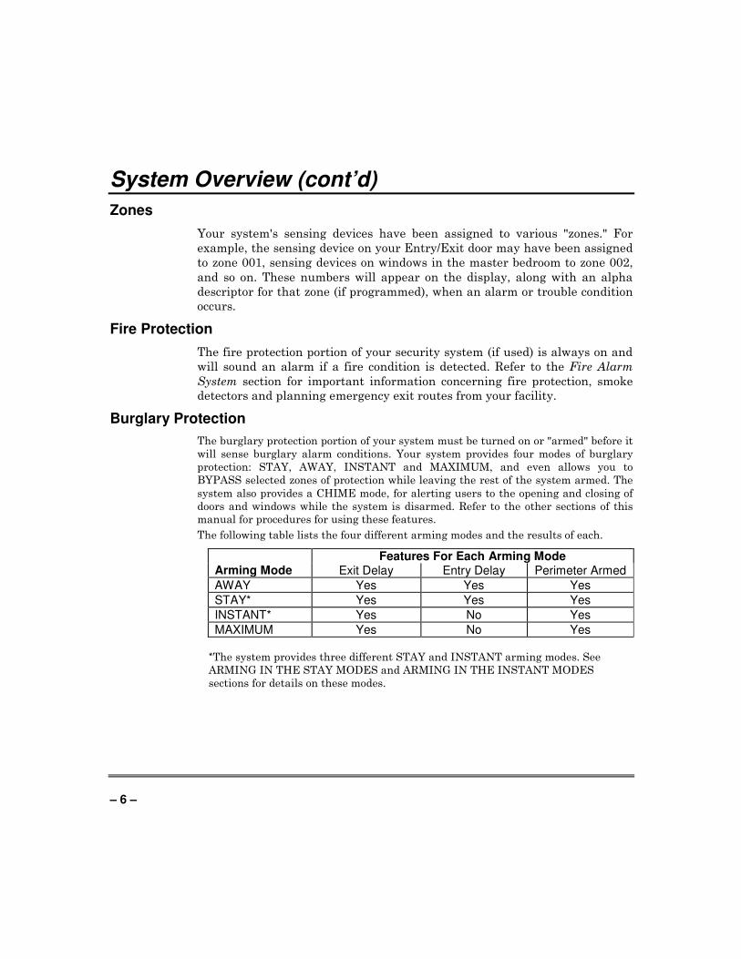
The following table lists the four different arming modes and the results of each.
Features For Each Arming Mode Arming Mode Exit Delay Entry Delay Perimeter Armed
AWAY Yes Yes Yes
STAY* Yes Yes Yes
INSTANT* Yes No Yes
MAXIMUM Yes No Yes
*The system provides three different STAY and INSTANT arming modes. See
ARMING IN THE STAY MODES and ARMING IN THE INSTANT MODES
sections for details on these modes.
– 7 –
System Overview (cont’d)
Carbon Monoxide Protection
Carbon monoxide (CO) protection is available with your system using the
5800CO Carbon Monoxide Detector. The 5800CO is a 3V battery powered
wireless Carbon Monoxide Detector used with wireless alarm systems that
support 5800 series devices. Carbon monoxide gas is a highly poisonous gas
which is released when fuels are burned. It is invisible, has no smell and is
therefore impossible to detect with the human senses. We strongly suggest
installing Carbon monoxide protection with your system.
Alarms
When an alarm occurs, both the keypad and external sounders will sound,
and the keypad will display the zone(s) causing the alarm. If your system is
connected to a central monitoring station, an alarm message will also be sent.
To stop the alarm sounding, simply disarm the system.
Memory of Alarm
When an alarm condition occurs, the keypad displays the number(s) of the
zone(s) that caused the problem, and displays the type of alarm (ex. FIRE,
ALARM). It remains displayed until it is cleared by disarming the system
(see Disarming the System section).
Using Schedules
Your system may have been programmed with schedules for automatically
arming, disarming and activating various devices and/or performing other
system functions at predetermined times. Users can modify some of these
schedules by manually delaying a closing time, using temporary schedules, or
by programming special user schedules. Refer to the Using Schedules section
at the end of this manual for scheduling related procedures.
– 8 –
System Overview (cont’d)
Device Timers
The system provides up to 20 "timers" that can be used to control various
devices, such as lights or appliances. These timers are similar in concept to
the individual appliance timers that might be purchased at a department
store. The devices that can be controlled are programmed into the system by
the installer. Up to 96 of these devices can be programmed. Refer to the
Programming Device Timers section for procedures.
To Access another Partition (GOTO Command)
Each keypad is assigned a default partition for display purposes, and will
show only that partition's information. But, if the user is authorized, a
keypad in one partition can be used to perform system functions in another
partition, by using the GOTO command. Note that only those partitions
authorized and programmed by the installer can be accessed in this manner.
To GOTO another partition, enter your security code, then press [∗] followed
by the desired partition number (1-2).
The keypad will remain in the new partition until directed to go to another
partition, or until 2 minutes has elapsed with no keypad activity. Entering
your security code, pressing [∗∗∗∗] followed by [0] will return the keypad to its
original partition.
Master Keypad Operation
A "Master" keypad is one on which the status of all eight partitions is
displayed simultaneously. A user can get more information about a certain
partition by simply entering [∗∗∗∗] + the desired partition number (1-2). To log
on to the "Master" partition (3) using the GOTO command, and to perform
any functions at a Master keypad, a user must have access to all partitions.
– 9 –
System Overview (cont’d)
Self-Help Feature
Abbreviated user instructions are built into the system that can be easily
viewed on the alpha keypad's message display screen. This feature will prove
particularly useful if this manual is not conveniently accessible when you
need to perform a system procedure with which you are not familiar.
To view the abbreviated instructions:
Simply press and hold down the function key of interest until the description
starts to appear (about 5 seconds) and then release it. The system must be
“READY TO ARM” to perform this function.
Refer to the Functions of the Keypad section for descriptions of each key
function.
– 10 –
About The Keypads
General
IMPORTANT: If the keypad beeps rapidly upon entering the premises, it indicates that an alarm has occurred during your absence. LEAVE the premises IMMEDIATELY and CONTACT THE POLICE from a safe location nearby.
Your keypads allow you to control all system functions. The keypads feature
a telephone style (digital) keypad and a Liquid Crystal Display (LCD) that
shows the nature and location of all occurrences. Keypad display back
lighting is programmable to always stay on or to light only when a key is
pressed, then turn off a few minutes later.
The keypads also feature a built-in sounder that will sound during alarms
and troubles. It will also "beep" during certain system functions, such as
during entry/exit delay times, during CHIME mode, and when depressing
keys to perform system functions (to acknowledge the key press). These
sounds can be optionally suppressed in some of your keypads (so as not to
disturb other users of the system). Ask your installer if this has been done.
The Alpha Keypad
Alpha keypads feature a 2-line, 32-character alphanumeric LCD that can
display system messages in user-friendly English. Abbreviated user
instructions can also be displayed (see Self Help paragraph in the SYSTEM
OVERVIEW section). These keypads can also be programmed with custom
zone descriptors.
NOTE: There may be multiple keypads on your system. One, the primary
keypad, will continue to operate under faulted conditions.
– 11 –
Functions of the Keypad
1 OFF
4 MAX
7 INSTANT
READY
2 AWAY
5 TEST
8 CODE
0
3 STAY
6 BYPASS
9 CHIME
#
SILENCED
TROUBLE
ALARM
SUPV
POWER
6160C
R2-0
01-V
0
ARMED
READY
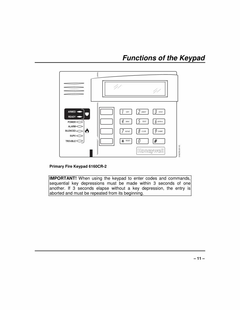
Primary Fire Keypad 6160CR-2
IMPORTANT! When using the keypad to enter codes and commands, sequential key depressions must be made within 3 seconds of one another. If 3 seconds elapse without a key depression, the entry is aborted and must be repeated from its beginning.
– 12 –
Functions of the Keypad (cont’d)
1 OFF
4 MAX
7 INSTANT
READY
2 AWAY
5 TEST
8 CODE
0
3 STAY
6BYPASS
9CHIME
#
ARMED
READY
61
60
-00
-00
1-V
0
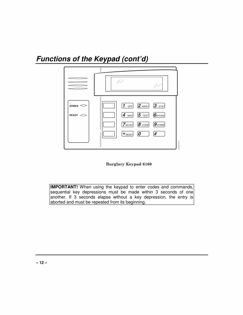
Burglary Keypad 6160
IMPORTANT! When using the keypad to enter codes and commands, sequential key depressions must be made within 3 seconds of one another. If 3 seconds elapse without a key depression, the entry is aborted and must be repeated from its beginning.
–13 –
Functions of the Keypad (cont’d)
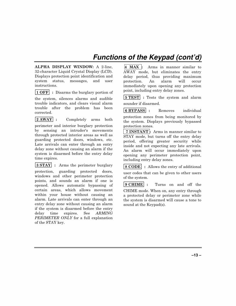
ALPHA DISPLAY WINDOW: A 2-line,
32-character Liquid Crystal Display (LCD).
Displays protection point identification and
system status, messages, and user
instructions.
1 OFF : Disarms the burglary portion of
the system, silences alarms and audible
trouble indicators, and clears visual alarm
trouble after the problem has been
corrected.
2 AWAY : Completely arms both
perimeter and interior burglary protection
by sensing an intruder's movements
through protected interior areas as well as
guarding protected doors, windows, etc.
Late arrivals can enter through an entry
delay zone without causing an alarm if the
system is disarmed before the entry delay
time expires.
3 STAY : Arms the perimeter burglary
protection, guarding protected doors,
windows and other perimeter protection
points, and sounds an alarm if one is
opened. Allows automatic bypassing of
certain areas, which allows movement
within your house without causing an
alarm. Late arrivals can enter through an
entry delay zone without causing an alarm
if the system is disarmed before the entry
delay time expires. See ARMING
PERIMETER ONLY for a full explanation
of the STAY key.
4 MAX : Arms in manner similar to
AWAY mode, but eliminates the entry
delay period, thus providing maximum
protection. An alarm will occur
immediately upon opening any protection
point, including entry delay zones.
5 TEST : Tests the system and alarm
sounder if disarmed.
6 BYPASS : Removes individual
protection zones from being monitored by
the system. Displays previously bypassed
protection zones.
7 INSTANT : Arms in manner similar to
STAY mode, but turns off the entry delay
period, offering greater security while
inside and not expecting any late arrivals.
An alarm will occur immediately upon
opening any perimeter protection point,
including entry delay zones.
8 CODE : Allows the entry of additional
user codes that can be given to other users
of the system.
9 CHIME : Turns on and off the
CHIME mode. When on, any entry through
a protected delay or perimeter zone while
the system is disarmed will cause a tone to
sound at the Keypad(s).

– 14 –
Functions of the Keypad (cont’d)
S READY : When depressed prior to
arming the system, the keypad will display
all open protection zones within the
keypad's home partition. This key is also
used to display all zone descriptors that
have been programmed for your system, by
holding the key down for at least 5 seconds.
# : Permits ARMING of the system
without use of a security code ("Quick
Arm", if programmed).
KEYS 0-9: Used to enter your individual
security access code(s).
LED READY INDICATOR: (GREEN) Lit
indicates system is ready to be armed,
while unlit indicates system not ready.
LED ARMED INDICATOR: (RED) Lit
when the system has been armed (STAY,
AWAY, INSTANT or MAXIMUM).
LED POWER INDICATOR: (GREEN) Lit
when AC power is applied to the system.
LED ALARM INDICATOR: (RED) Lit
when any Fire Alarm exists in the system.
LED SILENCED INDICATOR: (AMBER)
Lit when CODE + OFF is pressed.
LED SUPV INDICATOR: (AMBER) Lit
when a supervisory condition exists in the
system.
LED TROUBLE INDICATOR: (AMBER)
Lit when a trouble condition exists in the
system.
SPEAKER: Source of audible internal
warning and confirmation sounds, as well
as alarms (see "Summary of Audible
Notifications").
FUNCTION KEYS: These keys can be
used for panic keys. Refer to the Panic Keys
section for descriptions of these functions.
– 15 –
Entry/Exit Delays
General Information
Your system has installer-programmed time delays, known as exit delay and
entry delay. Whenever you arm your system, exit delay gives you time to
leave through the designated exit door without setting off an alarm. Exit
delay begins immediately after entering any arming command, and applies to
all modes of arming protection. If programmed, a slow beeping will sound
throughout the exit delay period.
Entry Delay gives you time to disarm the system when you reenter through
the designated entrance door. But the system must be disarmed before the
entry delay period ends, or an alarm will occur. The keypad will beep during
the entry delay period, reminding you to disarm the system. You can also
arm the system with no entry delay at all by using either INSTANT or
MAXIMUM arming modes. These modes provide greater security while on
the premises or while away for extended periods of time. See your installer
for your delay times.

– 16 –
Security Codes and Authority Levels
General Information
At the time of installation, you were assigned an authority level and a
personal 4-digit security code, known only to you and yours. The security
code must be entered when arming and disarming the system. The authority
level defines the system functions that you can perform.
As an additional safety feature, other users that do not have a need to know
your code can be assigned different security codes, and each user can be given
a different authority level. Users are identified by "user numbers", which are
assigned when assigning a user's security code.
All codes can be used interchangeably when performing system functions
within the limits of each code's authority level (a system armed with one
user's code can be disarmed by another user's code), with the exception of the
Operator Level C code. See Authority Levels paragraph on the following page
for details regarding authority levels.
Duress Code
This feature is intended for use if you are forced to disarm or arm the system
under threat. When used, the system will act normally, but can silently
notify the central station of your situation, if that service has been provided.
The duress code is pre-assigned by the installer during installation (authority
level 6).
IMPORTANT: This code is useful only when the system is connected to a
central station.
Quick Arming
Note: If "Quick Arming" was programmed by the installer, the [#] key can be
pressed in place of the security code when arming the system. The security
code must always be used to disarm the system, however.
– 17 –
Security Codes and Authority Levels (cont’d)
Authority Levels
Authority levels define the system functions a particular user can perform.
Depending on the authority assigned to you, there are certain system
functions you may be prohibited from performing. In summary, there are six
authority levels, each having certain system restrictions as shown below.
Level 1 Master: Can perform all system functions in assigned
partitions, and can add, delete or change Manager
and Operator level users. The Installer adds
master codes.
Level 2 Manager: Can perform system functions in assigned
partitions, and can add, delete or change Operator
level users.
Level 3 Operator A: Can perform system functions in assigned
partitions, but cannot add or delete other users.
Level 4 Operator B: Same as Operator A, except Operator B cannot
bypass zones of protection.
Level 5 Operator C: Can arm the system in assigned partitions, but
cannot disarm the system unless the system was
armed with this code. This code is typically
assigned to someone who has a need to
arm/disarm the system only at certain times (such
as a baby-sitter).
Level 6 Duress: Can arm and disarm the system, but also sends a
silent panic alarm to the central station, if that
service is connected.
To view your authority level and system capabilities:
1. Enter your code + [∗∗∗∗] + [∗∗∗∗].
2. The keypad will display the partition(s) that you are authorized to
operate, and your user number and authority level in each partition.
– 18 –
Security Codes and Authority Levels (cont’d)
General Rules on Authority Levels and Changes
• A user may not delete or change the user code of the SAME or HIGHER
authority than which he is assigned.
• A user may only ADD users to a LOWER authority level.
• A user may assign access codes only to those partitions to which the user
adding the code has access. (Ex. a user with access to only partition 1
cannot assign codes in partition 2.)
• The only way to assign a user's authority level is by using the "Add A
User" procedure. To change a user's authority level, that user must first
be deleted, and then added again.
• A user can only be DELETED or CHANGED from within the partition he
is assigned.
• User numbers must be entered as 2-digit entries. Single digit user
numbers must be preceded by a "0" (example, 03, 04, etc.). Security codes
are entered as 4-digit numbers.
• Before assigning a security code, be sure it does not conflict with any
DURESS code.
NOTE: When adding, changing or deleting users, all other alpha keypads in
that partition will display "User Edit Mode – Please Stand By", and key
depressions (except Panic) at those keypads will be ignored. Panic key
depressions will cause an alarm and terminate user entry.
To Exit User Edit Mode
You can exit any of the user edit modes described on the following pages at
any time by doing the following:
1. Press either S or # , or don't press any key for 10 seconds.
2. System returns to normal mode.
– 19 –
Security Codes and Authority Levels (cont’d)
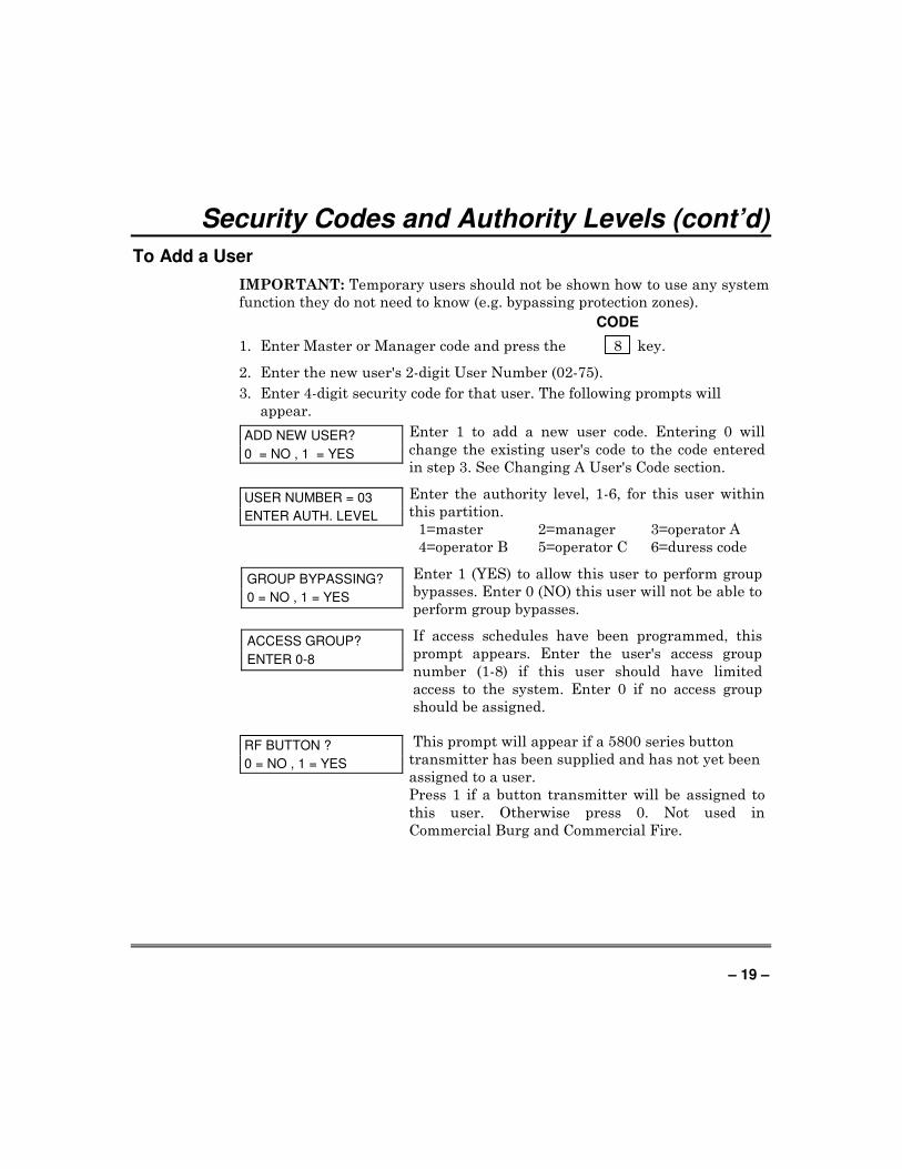
To Add a User
IMPORTANT: Temporary users should not be shown how to use any system
function they do not need to know (e.g. bypassing protection zones).
CODE
1. Enter Master or Manager code and press the 8 key.
2. Enter the new user's 2-digit User Number (02-75).
3. Enter 4-digit security code for that user. The following prompts will
appear.
ADD NEW USER?
0 = NO , 1 = YES
Enter 1 to add a new user code. Entering 0 will
change the existing user's code to the code entered
in step 3. See Changing A User's Code section.
USER NUMBER = 03
ENTER AUTH. LEVEL
Enter the authority level, 1-6, for this user within
this partition.
1=master 2=manager 3=operator A
4=operator B 5=operator C 6=duress code
GROUP BYPASSING?
0 = NO , 1 = YES
Enter 1 (YES) to allow this user to perform group
bypasses. Enter 0 (NO) this user will not be able to
perform group bypasses.
ACCESS GROUP?
ENTER 0-8
If access schedules have been programmed, this
prompt appears. Enter the user's access group
number (1-8) if this user should have limited
access to the system. Enter 0 if no access group
should be assigned.
RF BUTTON ?
0 = NO , 1 = YES
This prompt will appear if a 5800 series button
transmitter has been supplied and has not yet been
assigned to a user.
Press 1 if a button transmitter will be assigned to
this user. Otherwise press 0. Not used in
Commercial Burg and Commercial Fire.
– 20 –
Security Codes and Authority Levels (cont’d)
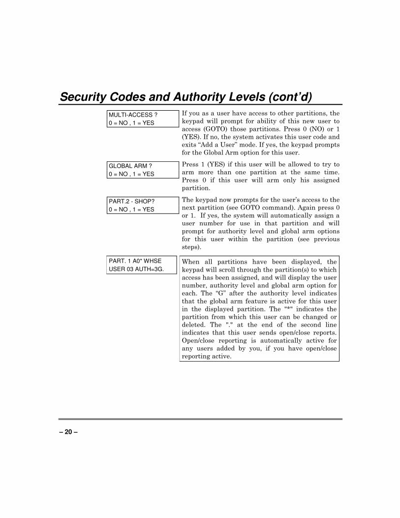
MULTI-ACCESS ?
0 = NO , 1 = YES
If you as a user have access to other partitions, the
keypad will prompt for ability of this new user to
access (GOTO) those partitions. Press 0 (NO) or 1
(YES). If no, the system activates this user code and
exits “Add a User” mode. If yes, the keypad prompts
for the Global Arm option for this user.
GLOBAL ARM ?
0 = NO , 1 = YES
Press 1 (YES) if this user will be allowed to try to
arm more than one partition at the same time.
Press 0 if this user will arm only his assigned
partition.
PART.2 - SHOP?
0 = NO , 1 = YES
The keypad now prompts for the user’s access to the
next partition (see GOTO command). Again press 0
or 1. If yes, the system will automatically assign a
user number for use in that partition and will
prompt for authority level and global arm options
for this user within the partition (see previous
steps).
PART. 1 A0* WHSE
USER 03 AUTH=3G.
When all partitions have been displayed, the
keypad will scroll through the partition(s) to which
access has been assigned, and will display the user
number, authority level and global arm option for
each. The “G” after the authority level indicates
that the global arm feature is active for this user
in the displayed partition. The "*" indicates the
partition from which this user can be changed or
deleted. The "." at the end of the second line
indicates that this user sends open/close reports.
Open/close reporting is automatically active for
any users added by you, if you have open/close
reporting active.
– 21 –
Security Codes and Authority Levels (cont’d)
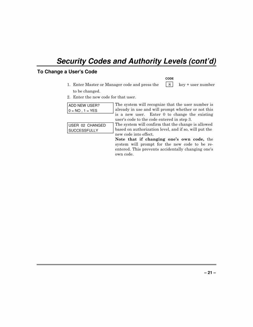
To Change a User's Code
CODE
1. Enter Master or Manager code and press the 8 key + user number
to be changed.
2. Enter the new code for that user.
ADD NEW USER?
0 = NO , 1 = YES
The system will recognize that the user number is
already in use and will prompt whether or not this
is a new user. Enter 0 to change the existing
user's code to the code entered in step 3.
USER 02 CHANGED
SUCCESSFULLY
The system will confirm that the change is allowed
based on authorization level, and if so, will put the
new code into effect.
Note that if changing one’s own code, the
system will prompt for the new code to be re-
entered. This prevents accidentally changing one's
own code.

– 22 –
Security Codes and Authority Levels (cont’d)
To Delete a User
CODE
1. Enter Master or Manager code and press the 8 key + user number
to be deleted.
2. Enter Master or Manager code first entered.
OK TO DELETE
0 = NO , 1 = YES
The system will recognize that the User number
is already in use and will prompt to confirm that
it should be deleted. Press 0 (NO) or 1 (YES).
USER CODE
DELETED
If yes, that user's code will be removed from all
partitions to which it was assigned, and all
authorization levels and other information about
that user will be deleted. Note that a user can
only be deleted from the partition in which it was
first assigned, and can only be deleted by a user
with a higher authority level. A User's security
code cannot be deleted by oneself.

– 23 –
Accessing Other Partitions
To Access another Partition
Each keypad is assigned a default partition for display purposes, and will
show only that partition's information. But, if the user is authorized, a
keypad in one partition can be used to perform system functions in other
partitions by using the GOTO command. Note that only those partitions
authorized and programmed by the installer can be accessed in this manner.
To GOTO another partition: READY
1. Enter your security code, then press S + partition number (0-2).
Entering partition number 0 will return the keypad to its original
partition.
2. LOG-ON TO AAAA PART. X COMPLETE
The keypad will remain in the new partition
until directed to go to another partition, or
until 2 minutes have elapsed with no keypad
activity.
AAAA = alpha descriptor programmed by the
installer
X = partition number
Global Arming
The Global Arming option may be assigned for use by some users. If Global
Arming was enabled for use with your security code, a keypad prompt
(message) shown below appears after pressing one of the arming function
keys (STAY, INSTANT, AWAY, MAXIMUM, OFF).
ARM P 1 2 HIT 0-2 X X
The prompt displays all the partitions. The user
may only arm/disarm the partitions they are
assigned access to.
To select the partition(s) that are to be armed,
enter the desired number 1-2. An "X" will appear
under that partition. Entering a partition's
number again will delete the “X” and that
partition will not arm when this prompt is exited.
Pressing 0 will turn all partitions the user is
assigned access to on/off.
When completed, press ∗ to exit. All the partitions
with the “X” will then arm/disarm.
– 24 –
Accessing Other Partitions (cont’d)
Global Arming Notes:
• When performing a Global Arm, if there are faults in any of the selected
partitions, the system will enter a Summary Mode. Faulted zones in all
the selected partitions will be displayed. These faults must be corrected
or bypassed. This Summary Mode will end in approximately 2 minutes if
no keys are pressed.
• When performing a Global Disarm, if any of the selected partitions has a
condition that would cause the keypad to beep (e.g., alarm memory or a
trouble condition), the system enters a Summary Mode and displays the
condition. This Summary Mode will end in approximately 2 minutes if no
keys are pressed.
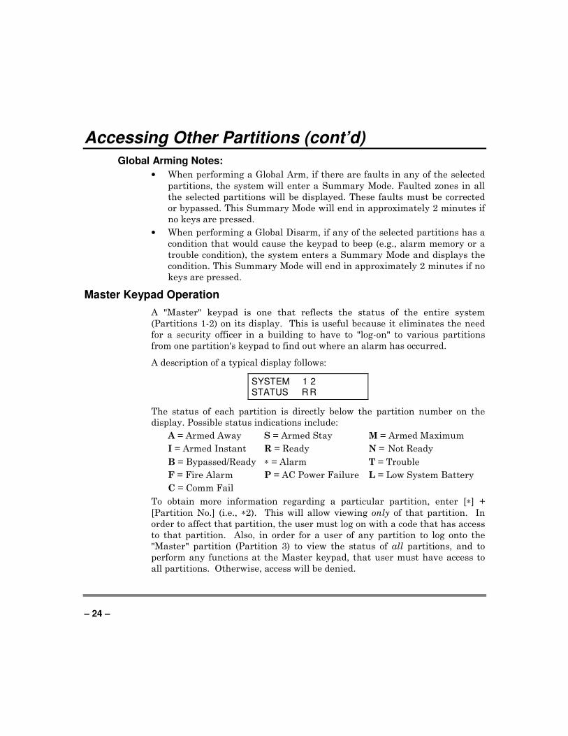
Master Keypad Operation
A "Master" keypad is one that reflects the status of the entire system
(Partitions 1-2) on its display. This is useful because it eliminates the need
for a security officer in a building to have to "log-on" to various partitions
from one partition's keypad to find out where an alarm has occurred.
A description of a typical display follows:
SYSTEM 1 2 STATUS R R
The status of each partition is directly below the partition number on the
display. Possible status indications include:
A = Armed Away S = Armed Stay M = Armed Maximum
I = Armed Instant R = Ready N = Not Ready
B = Bypassed/Ready ∗ = Alarm T = Trouble
F = Fire Alarm P = AC Power Failure L = Low System Battery
C = Comm Fail
To obtain more information regarding a particular partition, enter [∗] +
[Partition No.] (i.e., ∗2). This will allow viewing only of that partition. In
order to affect that partition, the user must log on with a code that has access
to that partition. Also, in order for a user of any partition to log onto the
"Master" partition (Partition 3) to view the status of all partitions, and to
perform any functions at the Master keypad, that user must have access to
all partitions. Otherwise, access will be denied.
– 25 –
Accessing Other Partitions (cont’d)
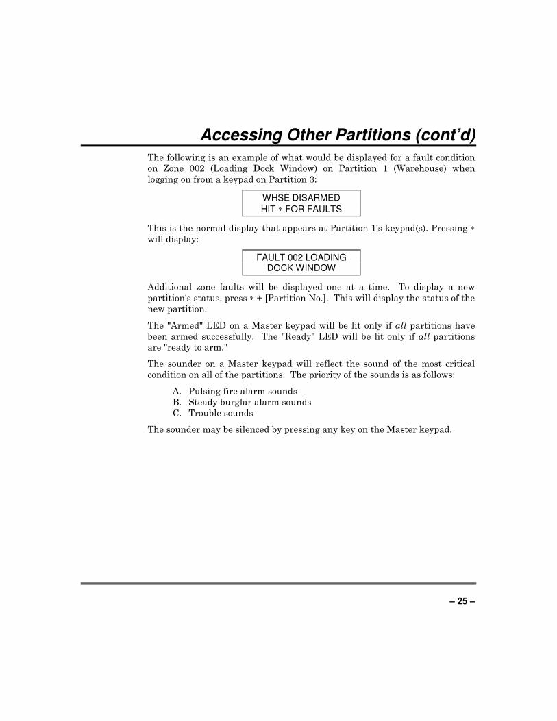
The following is an example of what would be displayed for a fault condition
on Zone 002 (Loading Dock Window) on Partition 1 (Warehouse) when
logging on from a keypad on Partition 3:
WHSE DISARMED
HIT ∗ FOR FAULTS
This is the normal display that appears at Partition 1's keypad(s). Pressing ∗
will display:
FAULT 002 LOADING DOCK WINDOW
Additional zone faults will be displayed one at a time. To display a new
partition's status, press ∗ + [Partition No.]. This will display the status of the
new partition.
The "Armed" LED on a Master keypad will be lit only if all partitions have
been armed successfully. The "Ready" LED will be lit only if all partitions
are "ready to arm."
The sounder on a Master keypad will reflect the sound of the most critical
condition on all of the partitions. The priority of the sounds is as follows:
A. Pulsing fire alarm sounds
B. Steady burglar alarm sounds
C. Trouble sounds
The sounder may be silenced by pressing any key on the Master keypad.
– 26 –
Accessing Other Partitions (cont’d)
Common Lobby Operation
When an installation consists of a partition that is shared by users of other
partitions in a building, the shared partition may be assigned as a “common
lobby” partition for the system. An example of this might be in a medical
building where there are two doctors and a common entrance area.
This option employs logic for automatic arming and disarming of the common
lobby. Partitions may be set to affect and/or attempt to arm the common
lobby. This will affect the way the lobby will react when arming or disarming
activity occurs in another partition.
Partitions that affect the lobby will cause the following to occur:
a. When the first partition that affects the lobby is disarmed, the lobby will
also be disarmed.
b. The common lobby cannot be armed unless every partition selected to
affect the lobby is armed.
c. Arming the last partition that affects the lobby will not automatically
attempt to arm the lobby.
Partitions set to arm the lobby will cause the following to occur:
a. Arming any partition programmed to arm the lobby will automatically
attempt to arm the lobby. If any faults exist in the lobby partition, or
another partition that affects the lobby is disarmed, the lobby cannot be
armed, and the message “UNABLE TO ARM LOBBY PARTITION” will
be displayed.
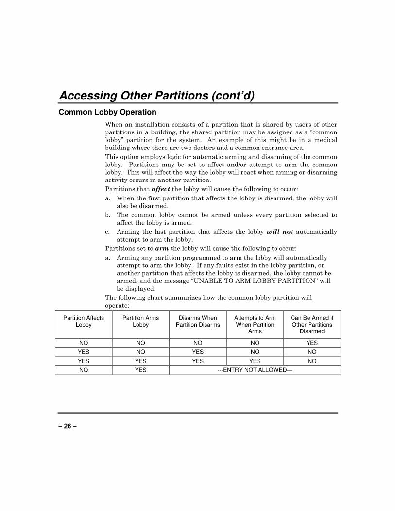
The following chart summarizes how the common lobby partition will
operate:
Partition Affects Lobby
Partition Arms Lobby
Disarms When Partition Disarms
Attempts to Arm When Partition
Arms
Can Be Armed if Other Partitions
Disarmed
NO NO NO NO YES
YES NO YES NO NO
YES YES YES YES NO
NO YES ---ENTRY NOT ALLOWED---
– 27 –
Accessing Other Partitions (cont’d)
How User Codes Affect the Common Lobby
Codes with “Global” Arming
If your code is given “global arming” when it is defined, the system displays a
prompt that allows you to pick and choose the partitions to be armed or
disarmed. This eliminates the “automatic” operation of the lobby. Keep in
mind, however, that if attempting to arm all the partitions you have access
to, and another affecting partition is disarmed, (one you do not have access
to) you will not be able to arm the lobby, and the message “UNABLE TO
ARM LOBBY PARTITON” will be displayed.
Codes with “Non-Global” Arming
If arming with a non-global code, the lobby partition operation will be
automatic, as described in the previous table.
Other Methods of Arming/Disarming
When arming or disarming a partition that affects and/or arms the common
lobby in one of the following manners, lobby logic remains active:
• Quick-Arm
• Keyswitch
• Wireless Button
• Wireless Keypad
– 28 –
Checking For Open Zones
Using the TTTT READY Key
Before arming your system, all protected doors, windows and other protection
zones must be closed or bypassed (see BYPASSING section). Otherwise the
keypad will display a "Not Ready" message. Using the ∗ READY key will
display all zones that are faulted, making it easier for you to secure any open
zones.
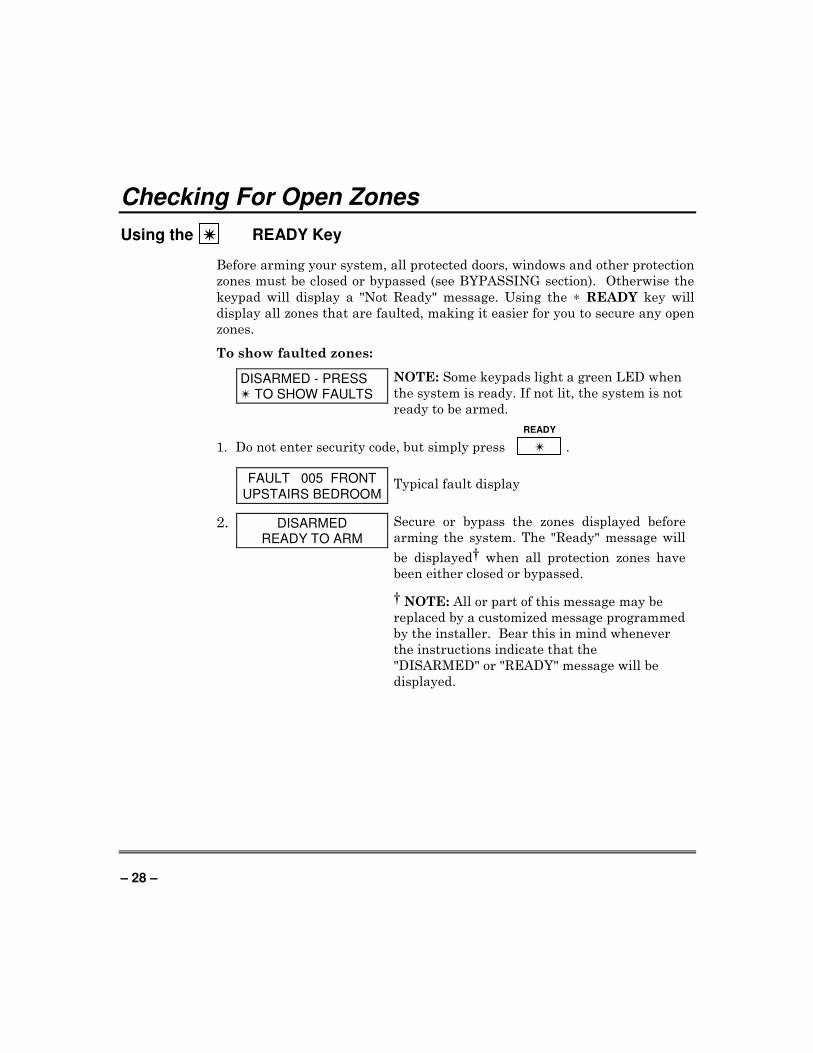
To show faulted zones:
DISARMED - PRESS T TO SHOW FAULTS
NOTE: Some keypads light a green LED when
the system is ready. If not lit, the system is not
ready to be armed.
READY
1. Do not enter security code, but simply press T .
FAULT 005 FRONT
UPSTAIRS BEDROOM Typical fault display
2. DISARMED READY TO ARM
Secure or bypass the zones displayed before
arming the system. The "Ready" message will
be displayed† when all protection zones have
been either closed or bypassed.
† NOTE: All or part of this message may be
replaced by a customized message programmed
by the installer. Bear this in mind whenever
the instructions indicate that the
"DISARMED" or "READY" message will be
displayed.
– 29 –
Displaying All Zone Descriptors
Using the SSSS READY Key
The Alpha Keypads can also display all the zone descriptors that are
programmed in your system. The abbreviated instructions for the READY
key will appear first, followed by the zone descriptors. Displaying all
descriptors is useful when you need to know the zone number of a particular
zone, as when bypassing zones.
The "Disarmed-Ready to arm" message must be displayed before zone
descriptors can be displayed.
READY
Press the S key and hold down for at least 5 seconds.
– 30 –
Bypassing Protection Zones
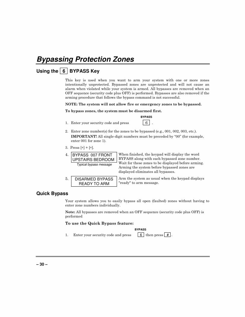
Using the 6 BYPASS Key
This key is used when you want to arm your system with one or more zones
intentionally unprotected. Bypassed zones are unprotected and will not cause an
alarm when violated while your system is armed. All bypasses are removed when an
OFF sequence (security code plus OFF) is performed. Bypasses are also removed if the
arming procedure that follows the bypass command is not successful.
NOTE: The system will not allow fire or emergency zones to be bypassed.
To bypass zones, the system must be disarmed first.
BYPASS
1. Enter your security code and press 6 .
2. Enter zone number(s) for the zones to be bypassed (e.g., 001, 002, 003, etc.).
IMPORTANT! All single-digit numbers must be preceded by “00” (for example,
enter 001 for zone 1).
3. Press [∗] + [∗].
4. BYPASS 007 FRONT UPSTAIRS BEDROOM
Typical bypass message
When finished, the keypad will display the word
BYPASS along with each bypassed zone number.
Wait for these zones to be displayed before arming.
Arming the system before bypassed zones are
displayed eliminates all bypasses.
5. DISARMED BYPASS READY TO ARM
Arm the system as usual when the keypad displays
"ready" to arm message.
Quick Bypass
Your system allows you to easily bypass all open (faulted) zones without having to
enter zone numbers individually.
Note: All bypasses are removed when an OFF sequence (security code plus OFF) is
performed
To use the Quick Bypass feature:
BYPASS
1. Enter your security code and press 6 then press # .
– 31 –
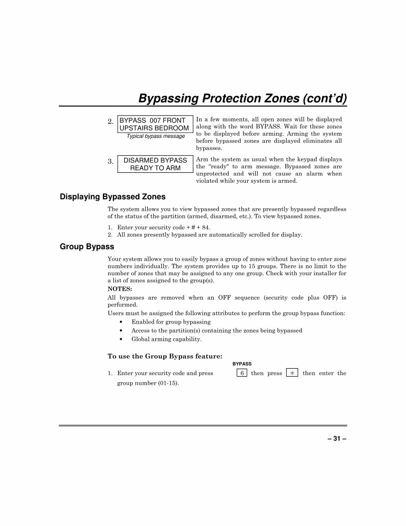
Bypassing Protection Zones (cont’d)
2. BYPASS 007 FRONT UPSTAIRS BEDROOM
Typical bypass message
In a few moments, all open zones will be displayed
along with the word BYPASS. Wait for these zones
to be displayed before arming. Arming the system
before bypassed zones are displayed eliminates all
bypasses.
3. DISARMED BYPASS READY TO ARM
Arm the system as usual when the keypad displays
the "ready" to arm message. Bypassed zones are
unprotected and will not cause an alarm when
violated while your system is armed.
Displaying Bypassed Zones
The system allows you to view bypassed zones that are presently bypassed regardless
of the status of the partition (armed, disarmed, etc.). To view bypassed zones.
1. Enter your security code + # + 84.
2. All zones presently bypassed are automatically scrolled for display.
Group Bypass
Your system allows you to easily bypass a group of zones without having to enter zone
numbers individually. The system provides up to 15 groups. There is no limit to the
number of zones that may be assigned to any one group. Check with your installer for
a list of zones assigned to the group(s).
NOTES:
All bypasses are removed when an OFF sequence (security code plus OFF) is
performed.
Users must be assigned the following attributes to perform the group bypass function:
• Enabled for group bypassing
• Access to the partition(s) containing the zones being bypassed
• Global arming capability.
To use the Group Bypass feature: BYPASS
1. Enter your security code and press 6 then press S then enter the
group number (01-15).
– 32 –
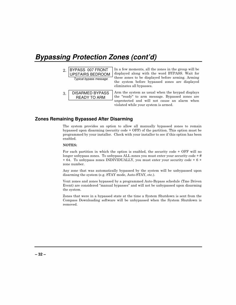
Bypassing Protection Zones (cont’d)
2. BYPASS 007 FRONT UPSTAIRS BEDROOM
Typical bypass message
In a few moments, all the zones in the group will be
displayed along with the word BYPASS. Wait for
these zones to be displayed before arming. Arming
the system before bypassed zones are displayed
eliminates all bypasses.
3. DISARMED BYPASS READY TO ARM
Arm the system as usual when the keypad displays
the "ready" to arm message. Bypassed zones are
unprotected and will not cause an alarm when
violated while your system is armed.
Zones Remaining Bypassed After Disarming
The system provides an option to allow all manually bypassed zones to remain
bypassed upon disarming (security code + OFF) of the partition. This option must be
programmed by your installer. Check with your installer to see if this option has been
enabled.
NOTES:
For each partition in which the option is enabled, the security code + OFF will no
longer unbypass zones. To unbypass ALL zones you must enter your security code + #
+ 64. To unbypass zones INDIVIDUALLY, you must enter your security code + 6 +
zone number.
Any zone that was automatically bypassed by the system will be unbypassed upon
disarming the system (e.g. STAY mode, Auto-STAY, etc.).
Vent zones and zones bypassed by a programmed Auto-Bypass schedule (Tme Driven
Event) are considered “manual bypasses” and will not be unbypassed upon disarming
the system.
Zones that were in a bypassed state at the time a System Shutdown is sent from the
Compass Downloading software will be unbypassed when the System Shutdown is
removed.
– 33 –
Arming Perimeter Only (With Entry Delay ON)
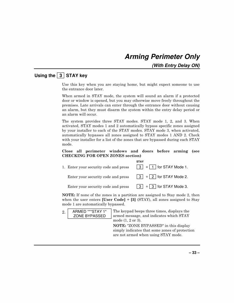
Using the 3 STAY key
Use this key when you are staying home, but might expect someone to use
the entrance door later.
When armed in STAY mode, the system will sound an alarm if a protected
door or window is opened, but you may otherwise move freely throughout the
premises. Late arrivals can enter through the entrance door without causing
an alarm, but they must disarm the system within the entry delay period or
an alarm will occur.
The system provides three STAY modes. STAY mode 1, 2, and 3. When
activated, STAY modes 1 and 2 automatically bypass specific zones assigned
by your installer to each of the STAY modes. STAY mode 3, when activated,
automatically bypasses all zones assigned to STAY modes 1 AND 2. Check
with your installer for a list of the zones that are bypassed during each STAY
mode.
Close all perimeter windows and doors before arming (see
CHECKING FOR OPEN ZONES section)
STAY
1. Enter your security code and press 3 + 1 for STAY Mode 1.
Enter your security code and press 3 + 2 for STAY Mode 2.
Enter your security code and press 3 + 3 for STAY Mode 3.
NOTE: If none of the zones in a partition are assigned to Stay mode 2, then
when the user enters [User Code] + [3] (STAY), all zones assigned to Stay
mode 1 are automatically bypassed.
2. ARMED ***STAY 1* ZONE BYPASSED
The keypad beeps three times, displays the
armed message, and indicates which STAY
mode (1, 2 or 3).
NOTE: "ZONE BYPASSED" in this display
simply indicates that some zones of protection
are not armed when using STAY mode.
– 34 –
Arming Perimeter Only (With Entry Delay ON) (cont’d)
Auto-STAY Arming
Auto-stay allows the system to automatically bypass certain zones if upon
arming none of the entry/exit zones are faulted during the exit delay time (no
one exits the premises). The system provides an option to set each burglary
zone for Auto-stay. All zones enabled for auto-stay except for perimeter and
day/night types of zones, has exit delay time when the partition is armed.
Check with your installer for the zones assigned for Auto-STAY.
NOTES:
• Auto-STAY applies to all four arming modes (AWAY, STAY, INSTANT
and MAXIMUM).
• Arming the partition AWAY via an RF transmitter overrides the Auto-
stay feature (partition will not bypass zones programmed for auto-stay).
– 35 –
Arming Perimeter Only (With Entry Delay OFF)
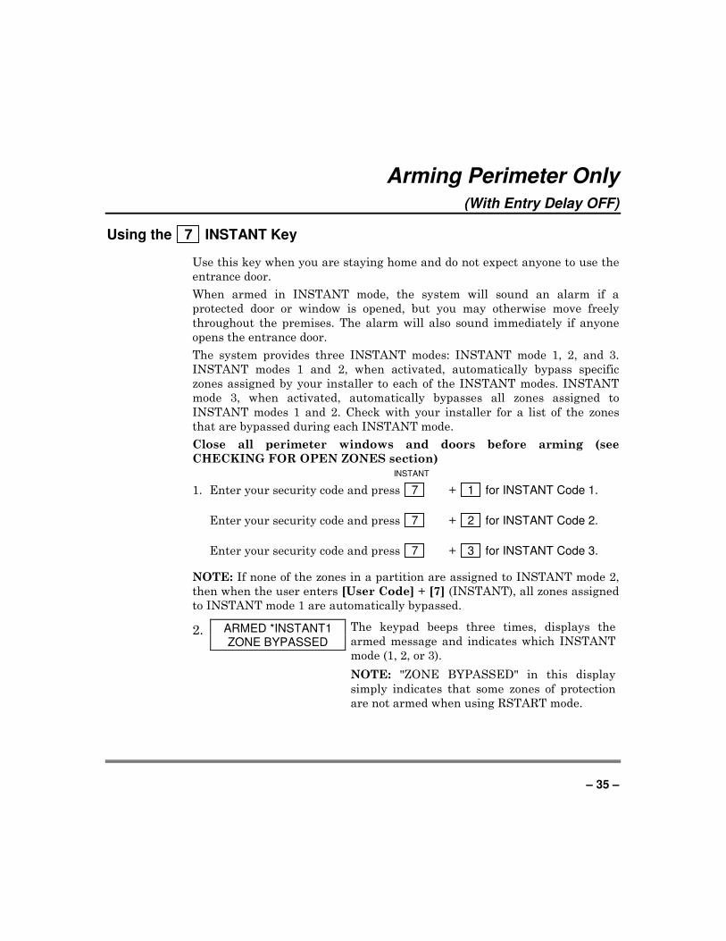
Using the 7 INSTANT Key
Use this key when you are staying home and do not expect anyone to use the
entrance door.
When armed in INSTANT mode, the system will sound an alarm if a
protected door or window is opened, but you may otherwise move freely
throughout the premises. The alarm will also sound immediately if anyone
opens the entrance door.
The system provides three INSTANT modes: INSTANT mode 1, 2, and 3.
INSTANT modes 1 and 2, when activated, automatically bypass specific
zones assigned by your installer to each of the INSTANT modes. INSTANT
mode 3, when activated, automatically bypasses all zones assigned to
INSTANT modes 1 and 2. Check with your installer for a list of the zones
that are bypassed during each INSTANT mode.
Close all perimeter windows and doors before arming (see
CHECKING FOR OPEN ZONES section) INSTANT
1. Enter your security code and press 7 + 1 for INSTANT Code 1.
Enter your security code and press 7 + 2 for INSTANT Code 2.
Enter your security code and press 7 + 3 for INSTANT Code 3.
NOTE: If none of the zones in a partition are assigned to INSTANT mode 2,
then when the user enters [User Code] + [7] (INSTANT), all zones assigned
to INSTANT mode 1 are automatically bypassed.
2. ARMED *INSTANT1 ZONE BYPASSED
The keypad beeps three times, displays the
armed message and indicates which INSTANT
mode (1, 2, or 3).
NOTE: "ZONE BYPASSED" in this display
simply indicates that some zones of protection
are not armed when using RSTART mode.
– 36 –
Arming All Protection (With Entry Delay ON)
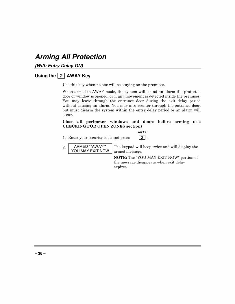
Using the 2 AWAY Key
Use this key when no one will be staying on the premises.
When armed in AWAY mode, the system will sound an alarm if a protected
door or window is opened, or if any movement is detected inside the premises.
You may leave through the entrance door during the exit delay period
without causing an alarm. You may also reenter through the entrance door,
but must disarm the system within the entry delay period or an alarm will
occur.
Close all perimeter windows and doors before arming (see
CHECKING FOR OPEN ZONES section)
AWAY
1. Enter your security code and press 2 .
2. ARMED **AWAY** YOU MAY EXIT NOW
The keypad will beep twice and will display the
armed message.
NOTE: The "YOU MAY EXIT NOW" portion of
the message disappears when exit delay
expires.
– 37 –
Arming all Protection (with Entry Delay OFF)
Using the 4 MAXIMUM Key
Use this key when the premises will be vacant for extended periods of time
such as vacations, etc., or when no one will be moving through protected
interior areas.
When armed in MAXIMUM mode, the system will sound an alarm if a
protected door or window is opened, or if any movement is detected inside the
premises. You may leave through the entrance door during the exit delay
period without causing an alarm, but an alarm will be sounded as soon as
someone reenters.
Close all perimeter windows and doors before arming (see Checking
for Open Zones section).
MAXIMUM
1. Enter your security code and press 4 .
2. ARMED *MAXIMUM* YOU MAY EXIT NOW
The keypad will beep twice and will display the
armed message.
NOTE: The "YOU MAY EXIT NOW" portion of
the message disappears when exit delay
expires.
– 38 –
Quick Exit
Using the # + 9 Keys
The Quick Exit feature allows you to exit the armed partition without having
to disarm and then rearm the partition.
To Quick Exit the premises:
1. Press the # key and then press the 9 key.
2. The system will sound the exit beeps, if enabled, and will give you the
programmed exit delay time to leave the premises.
– 39 –
Disarming and Silencing Alarms
Using the 1 OFF Key
The OFF key is used to disarm the system and to silence alarm and trouble
sounds. See Summary of Audible Notification section for information that
will help you to distinguish between FIRE and BURGLARY alarm sounds.
IMPORTANT: If you return and the main burglary sounder is on, DO NOT enter the premises, but call the police from a nearby safe location. If you return after an alarm has occurred and the main sounder has shut itself off, the keypad will beep rapidly upon entering, indicating that an alarm has occurred during your absence. LEAVE the premises IMMEDIATELY and CONTACT THE POLICE from a nearby safe location.
To disarm the system and silence burglary or fire alarms: OFF
1. Enter your security code and press 1 .
DISARMED READY TO ARM
2. The Ready message will be displayed (if no alarms have occurred while
armed) and the keypad will beep once to confirm that the system is
disarmed.
Memory of Alarm
The keypad displays the zone number and type of alarm for any zone that
has an alarm condition. These messages will remain displayed until cleared
by a user. If an alarm has occurred, note the zone number displayed on the
keypad and repeat step 1 above to clear the "Memory of Alarm" and restore
the Ready message display. If the Ready message will not display, go to the
displayed zone and remedy the fault (close windows, etc.). If the fault cannot
be remedied, notify the alarm agency.
If the system was armed when the alarm occurred, repeat step 1 twice: once
to disarm the system, a second time to clear the display.

– 40 –
Using the Keyswitch
General
Your system may be equipped with a keyswitch for use when arming and
disarming a partition. A red and green light on the keyswitch plate indicate
the status of your system as follows:
Green Light: Lights when the system is disarmed and ready to be
armed (no open zones). If the system is disarmed and the
green light is off, it indicates the system is not ready (one or
more zones are open).
Red Light: Lights when system is armed or memory of alarm exists.
Lit Steady: Partition is armed in AWAY mode.
Slow Flashing: Partition is armed in STAY mode.
Rapid Flashing: Memory of alarm, indicating an alarm has occurred.
Arming
To arm in the AWAY mode, turn the key to the right for 1 second and
release. Keypads will beep twice and the
red light will stay on steady.
To arm in the STAY mode, turn the
key to the right and hold for longer than
10 seconds, then release. Keypads will
beep three times and the red light will
flash slowly.
Disarming
To disarm the partition, turn the key
to the right and release. If an alarm has
occurred, the red light will be flashing
rapidly (memory of alarm).
NOTE: Your system may be
programmed to use the keyswitch to
silence fire alarms without affecting the
status of the burglary portion of the
system. Check with your installer to see
if this feature has been enabled.
GREEN RED
k e ys witch-001-V1
– 41 –
Chime Mode
Using the 9 Key
Your system can be set to alert you to the opening of a door or window while
it is disarmed by using CHIME mode. When activated, three tones will sound
at the Keypad whenever a protected perimeter door or window is opened, and
the Not Ready message will be displayed. Pressing the READY key will
display the open protection points.
Note that Chime mode can be activated only when the system is disarmed.
1. To turn Chime Mode on, enter the security code and press 9 .
CHIME MODE ON
The CHIME MODE ON message will appear
for about 2 seconds then disappear. To display
this message again (to determine whether
chime mode is on or off), simply press and hold
down the CHIME key for 5 seconds.
2. To turn Chime Mode off, enter the security code and press 9 again.
CHIME MODE OFF
The CHIME MODE OFF message will appear
for about 2 seconds then disappears. To display
this message again (to determine whether
chime mode is on or off), simply press and hold
down the CHIME key for 5 seconds.
– 42 –
Viewing Alarm Company Messages
General Information
Users of the system may periodically receive messages on their display
screens from their monitoring agency or installer. When a message is waiting
to be viewed, the message shown below will appear.
MESSAGE. PRESS 0 FOR 5 SECS.
1. Press and hold down 0 key for 5 seconds.
2. The message could take up to four screens to display all the information
available.
NOTE: Any message sent by the central station downloader may be viewed
at any partition’s keypad.

– 43 –
Panic Keys (For Manually Activating Silent and/or Audible Alarms)
Using Panic Keys
Your system may have been programmed to use special key combinations to
manually activate panic functions. The functions that might be programmed
are Silent Emergency, Audible Emergency, and Personal Emergency. See
your installer for the function(s) that may have been programmed for your
system.
Active Panic Functions
(Your installer should note which function(s) is active in your system.)
Keys Zone Function
1 and ∗ 995
3 and # 996
∗ and # 999
A 995
B 999
C 996
To use a paired key panic function, simply press both keys of the assigned pair at the same time.
If your keypad(s) have lettered keys for panic functions, press the designated key and hold down for at least 2 seconds to activate the panic function.
A silent emergency sends a silent alarm signal to the central station, but
there will be no audible alarms or visual displays.
An audible emergency sends an emergency message to the central station
(if connected) and will sound a loud, steady alarm at your keypad and at any
external sounders that may be connected (ALARM plus a zone number
would also be displayed).
A personal emergency alarm sends an emergency message to the central
station (if connected) and will sound at Keypads, but not at external
Notification Appliance Circuits. (ALARM plus a zone number would also be
displayed.)
– 44 –
Relay Control
General Information
Your system may be set up using a relay so that a door (such as in a lobby)
can be unlocked momentarily using a keypad command. Ask your installer if
this has been done in our system.
Executing
To activate the relay enter your security code + [0] at the keypad. The door
will unlock for 2 seconds.
– 45 –
Using #70 Relay Menu Mode
General Information
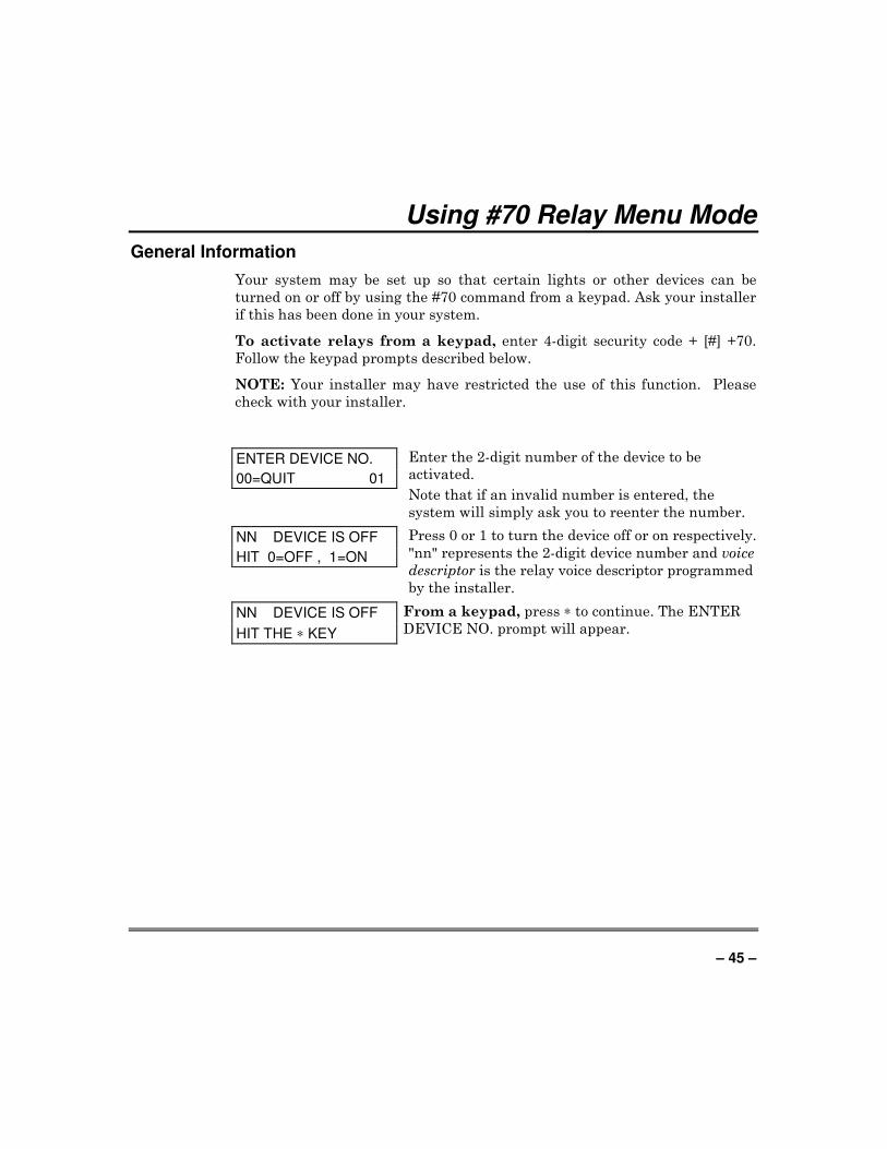
Your system may be set up so that certain lights or other devices can be
turned on or off by using the #70 command from a keypad. Ask your installer
if this has been done in your system.
To activate relays from a keypad, enter 4-digit security code + [#] +70.
Follow the keypad prompts described below.
NOTE: Your installer may have restricted the use of this function. Please
check with your installer.
ENTER DEVICE NO.
00=QUIT 01
Enter the 2-digit number of the device to be
activated.
Note that if an invalid number is entered, the
system will simply ask you to reenter the number.
NN DEVICE IS OFF
HIT 0=OFF , 1=ON
Press 0 or 1 to turn the device off or on respectively.
"nn" represents the 2-digit device number and voice
descriptor is the relay voice descriptor programmed
by the installer.
NN DEVICE IS OFF
HIT THE ∗ KEY
From a keypad, press ∗ to continue. The ENTER
DEVICE NO. prompt will appear.
– 46 –
Using Schedules
Delaying the Closing Time
Your system's programmed schedules may automatically arm the system at a
predetermined time. In the event a user must stay on the premises later than
usual, users with master or manager authority levels can manually delay the
automatic arming (closing) time up to 2 hours. To delay the closing time:
1. Enter your security code (master or manager authority levels only).
2. Press the # key, followed by 82.
3. A menu prompt will be displayed, asking for the number of hours of delay.
CLOSING DELAY?
KEY 0-2 HOURS
Enter the desired number of hours of delay, 1 or 2.
The system automatically exits this mode after
entry.
Note that the delay is from the scheduled closing time, not from the
time the command is entered.
IMPORTANT: The selected delay cannot be reduced once it is set. A 1-
hour delay can be increased to 2 hours, though.
4. The system will automatically send a message to the central station
informing them that the programmed schedule has been changed.
Temporary Open/Close Schedules
Temporary schedules allow you to override the normal schedules
programmed by the installer. Temporary schedules can be in effect for up to
one week, and take effect as soon as they are programmed.
They are comprised of an arming (closing) time window and a disarming
(opening) time window. A time window is simply a defined period of time, at
the end of which arming or disarming will occur.
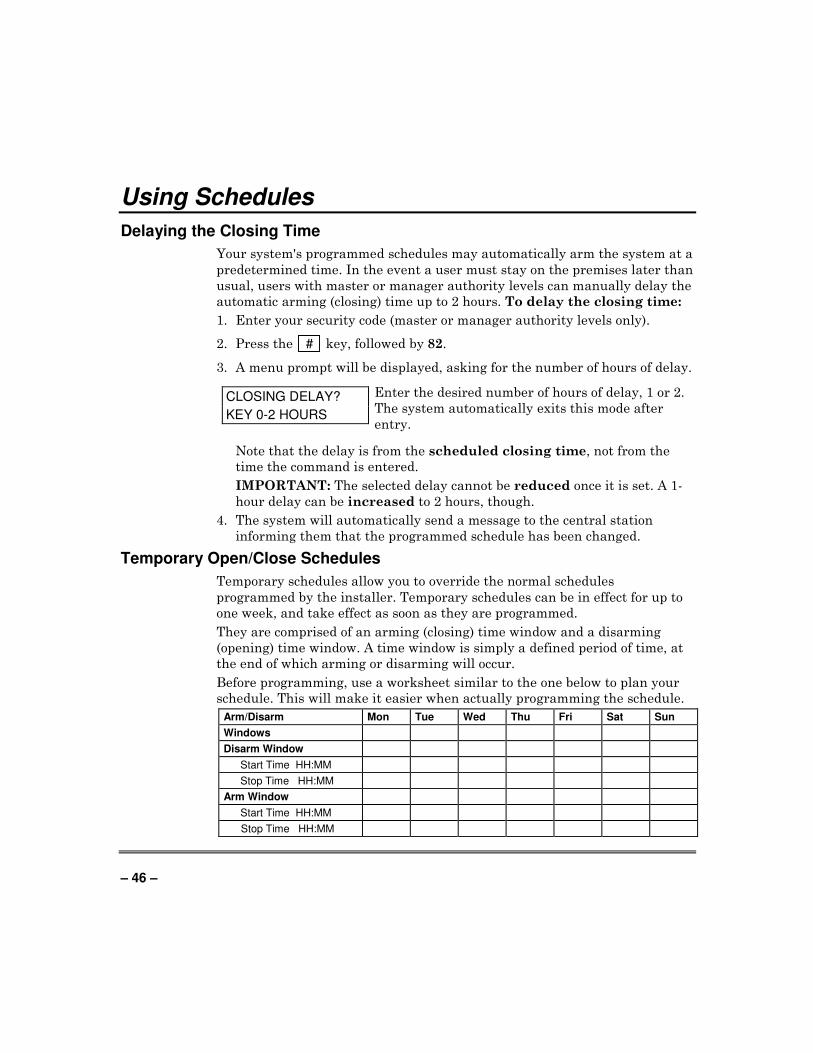
Before programming, use a worksheet similar to the one below to plan your
schedule. This will make it easier when actually programming the schedule.
Arm/Disarm Mon Tue Wed Thu Fri Sat Sun
Windows
Disarm Window
Start Time HH:MM
Stop Time HH:MM
Arm Window
Start Time HH:MM
Stop Time HH:MM
– 47 –
Using Schedules (cont’d)
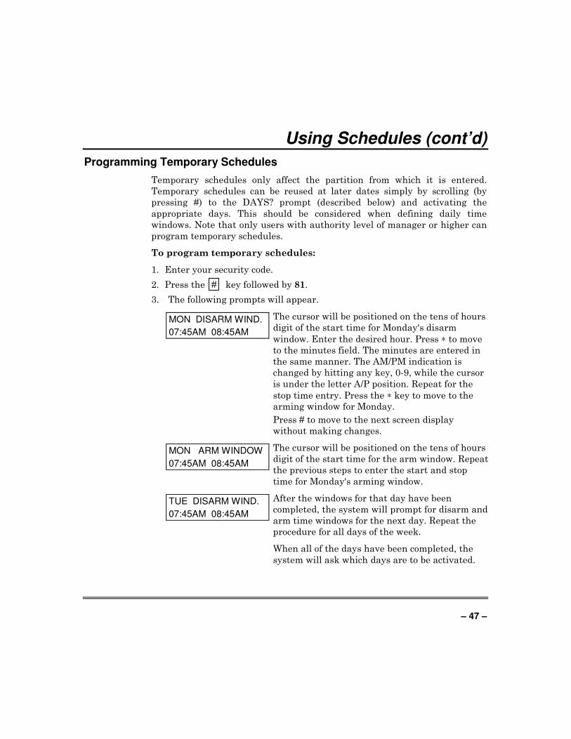
Programming Temporary Schedules
Temporary schedules only affect the partition from which it is entered.
Temporary schedules can be reused at later dates simply by scrolling (by
pressing #) to the DAYS? prompt (described below) and activating the
appropriate days. This should be considered when defining daily time
windows. Note that only users with authority level of manager or higher can
program temporary schedules.
To program temporary schedules:
1. Enter your security code.
2. Press the # key followed by 81.
3. The following prompts will appear.
MON DISARM WIND.
07:45AM 08:45AM
The cursor will be positioned on the tens of hours
digit of the start time for Monday's disarm
window. Enter the desired hour. Press ∗ to move
to the minutes field. The minutes are entered in
the same manner. The AM/PM indication is
changed by hitting any key, 0-9, while the cursor
is under the letter A/P position. Repeat for the
stop time entry. Press the ∗ key to move to the
arming window for Monday.
Press # to move to the next screen display
without making changes.
MON ARM WINDOW
07:45AM 08:45AM
The cursor will be positioned on the tens of hours
digit of the start time for the arm window. Repeat
the previous steps to enter the start and stop
time for Monday's arming window.
TUE DISARM WIND.
07:45AM 08:45AM
After the windows for that day have been
completed, the system will prompt for disarm and
arm time windows for the next day. Repeat the
procedure for all days of the week.
When all of the days have been completed, the
system will ask which days are to be activated.
– 48 –
Using Schedules (cont’d)
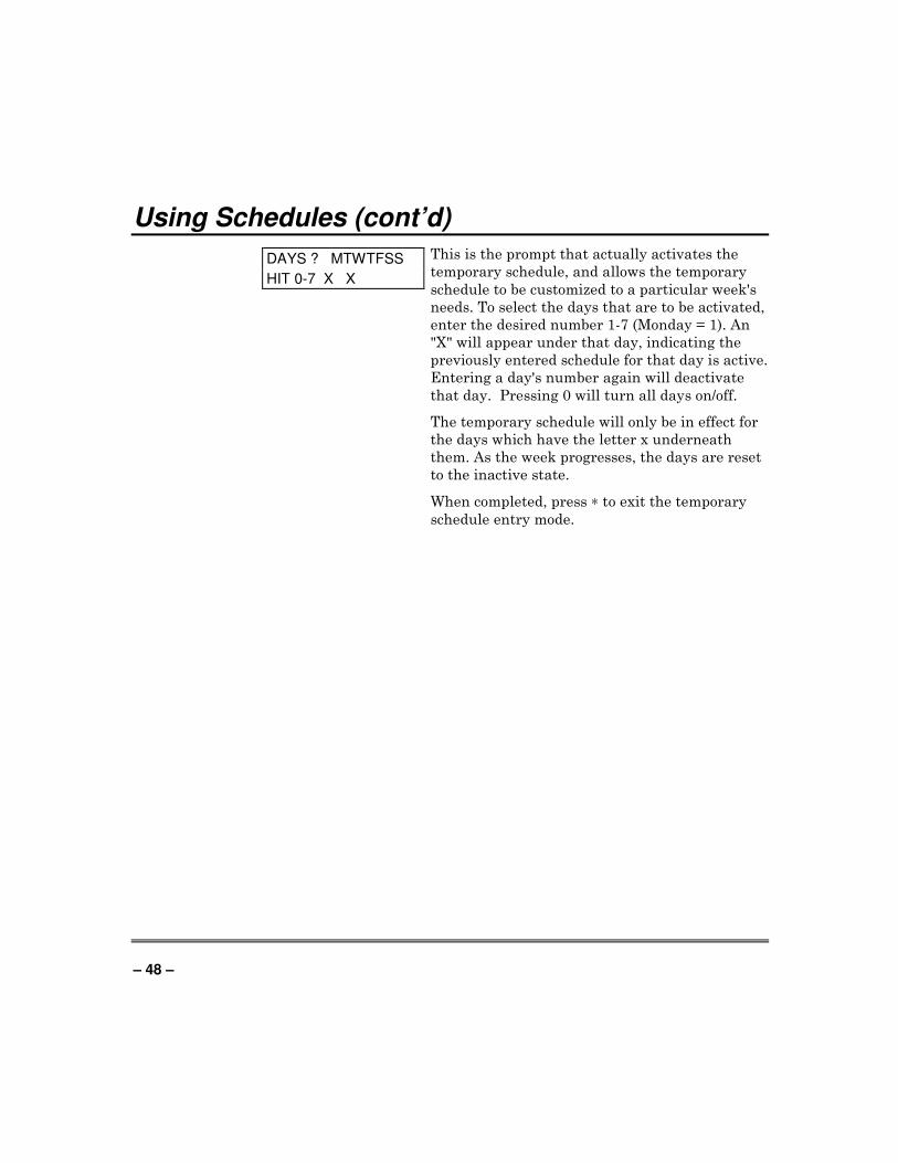
DAYS ? MTWTFSS
HIT 0-7 X X
This is the prompt that actually activates the
temporary schedule, and allows the temporary
schedule to be customized to a particular week's
needs. To select the days that are to be activated,
enter the desired number 1-7 (Monday = 1). An
"X" will appear under that day, indicating the
previously entered schedule for that day is active.
Entering a day's number again will deactivate
that day. Pressing 0 will turn all days on/off.
The temporary schedule will only be in effect for
the days which have the letter x underneath
them. As the week progresses, the days are reset
to the inactive state.
When completed, press ∗ to exit the temporary
schedule entry mode.
– 49 –
Programming Device Timers
General Information
Device timers consist of an ON time and an OFF time, and selected days of
the week in which they are active. There are up to 20 timers that can be used
to control various devices, such as lights or appliances. Your installer will
have programmed the appropriate devices into the system (up to 96 devices
can be programmed).
Each timer controls a single device (designated as an output number) that
you select. For example, timer 1 might be set to turn the porch lights on at
7:00pm and turn them off at 11:00pm. Timer 2 might turn on the air
conditioner Monday-Friday at 4:30pm to cool the premises before you arrive
at 5:00pm, and turn it off at 10:00pm when you are retiring for the night. If
desired, different timers can control the same device. For example, timer 2
could be used Monday-Friday as in the previous example, and timer 3 could
be set to turn the air conditioner on and off at different times Saturday and
Sunday.
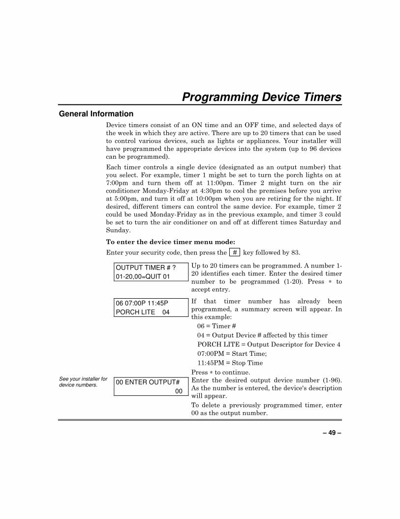
To enter the device timer menu mode:
Enter your security code, then press the # key followed by 83.
OUTPUT TIMER # ?
01-20,00=QUIT 01
Up to 20 timers can be programmed. A number 1-
20 identifies each timer. Enter the desired timer
number to be programmed (1-20). Press ∗ to
accept entry.
06 07:00P 11:45P
PORCH LITE 04
If that timer number has already been
programmed, a summary screen will appear. In
this example:
06 = Timer #
04 = Output Device # affected by this timer
PORCH LITE = Output Descriptor for Device 4
07:00PM = Start Time;
11:45PM = Stop Time
Press ∗ to continue. See your installer for device numbers. 00 ENTER OUTPUT#
00
Enter the desired output device number (1-96).
As the number is entered, the device's description
will appear.
To delete a previously programmed timer, enter
00 as the output number.
– 50 –
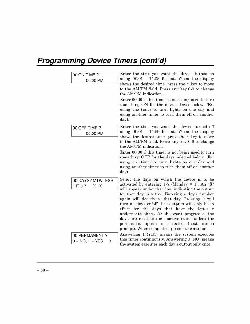
Programming Device Timers (cont’d)
00 ON TIME ?
00:00 PM
Enter the time you want the device turned on
using 00:01 - 11:59 format. When the display
shows the desired time, press the ∗ key to move
to the AM/PM field. Press any key 0-9 to change
the AM/PM indication.
Enter 00:00 if this timer is not being used to turn
something ON for the days selected below. (Ex.
using one timer to turn lights on one day and
using another timer to turn them off on another
day).
00 OFF TIME ?
00:00 PM
Enter the time you want the device turned off
using 00:01 - 11:59 format. When the display
shows the desired time, press the ∗ key to move
to the AM/PM field. Press any key 0-9 to change
the AM/PM indication.
Enter 00:00 if this timer is not being used to turn
something OFF for the days selected below. (Ex.
using one timer to turn lights on one day and
using another timer to turn them off on another
day).
00 DAYS? MTWTFSS
HIT 0-7 X X
Select the days on which the device is to be
activated by entering 1-7 (Monday = 1). An "X"
will appear under that day, indicating the output
for that day is active. Entering a day's number
again will deactivate that day. Pressing 0 will
turn all days on/off. The outputs will only be in
effect for the days that have the letter x
underneath them. As the week progresses, the
days are reset to the inactive state, unless the
permanent option is selected (next screen
prompt). When completed, press ∗ to continue.
00 PERMANENT ?
0 = NO, 1 = YES 0
Answering 1 (YES) means the system executes
this timer continuously. Answering 0 (NO) means
the system executes each day's output only once.

– 51 –
Programming Device Timers (cont’d)
Randomize Output Device Times
Devices in your system may be set for a random schedule, whereby they will
turn on and off at different times each day. This is useful when going on
vacation and you desire the turning on and off of the lights to the give the
appearance of someone being home. Your installer sets these devices for a
random schedule. You can initiate a random schedule by either of the
following methods:
1. Enter your security code and press # followed by 41.
This will randomize, up to 30 minutes, the activation time of all devices,
programmed for randomization, assigned to the partition the sequence is
entered in. Enter the sequence again to turn off the random schedule.
2. Enter your security code and press # followed by 42.
This is the same as the method above, except the randomization occurs
only on devices with activation times within 6 PM and 5 AM. Enter the
same sequence again to turn off the random schedule.
– 52 –
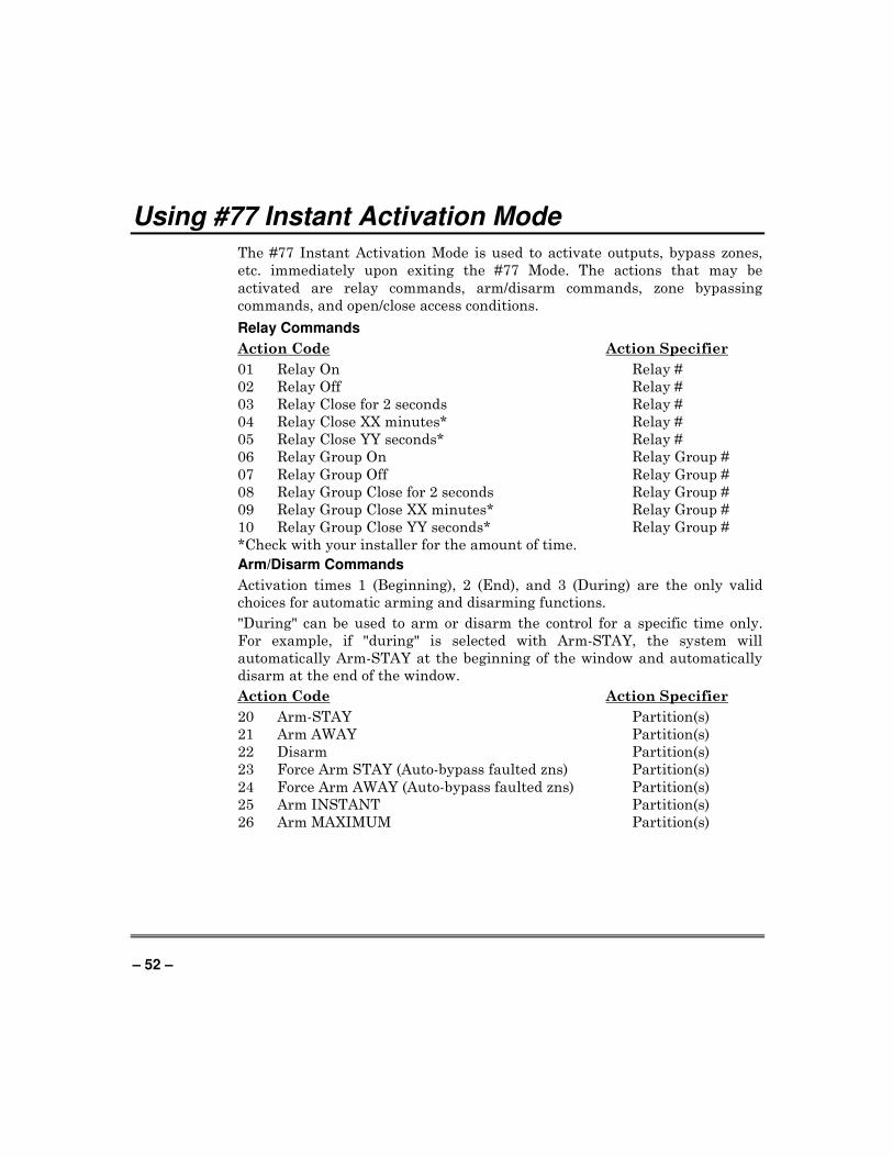
Using #77 Instant Activation Mode
The #77 Instant Activation Mode is used to activate outputs, bypass zones,
etc. immediately upon exiting the #77 Mode. The actions that may be
activated are relay commands, arm/disarm commands, zone bypassing
commands, and open/close access conditions.
Relay Commands
Action Code Action Specifier
01 Relay On Relay #
02 Relay Off Relay #
03 Relay Close for 2 seconds Relay #
04 Relay Close XX minutes* Relay #
05 Relay Close YY seconds* Relay #
06 Relay Group On Relay Group #
07 Relay Group Off Relay Group #
08 Relay Group Close for 2 seconds Relay Group #
09 Relay Group Close XX minutes* Relay Group #
10 Relay Group Close YY seconds* Relay Group #
*Check with your installer for the amount of time.
Arm/Disarm Commands
Activation times 1 (Beginning), 2 (End), and 3 (During) are the only valid
choices for automatic arming and disarming functions.
"During" can be used to arm or disarm the control for a specific time only.
For example, if "during" is selected with Arm-STAY, the system will
automatically Arm-STAY at the beginning of the window and automatically
disarm at the end of the window.
Action Code Action Specifier
20 Arm-STAY Partition(s)
21 Arm AWAY Partition(s)
22 Disarm Partition(s)
23 Force Arm STAY (Auto-bypass faulted zns) Partition(s)
24 Force Arm AWAY (Auto-bypass faulted zns) Partition(s)
25 Arm INSTANT Partition(s)
26 Arm MAXIMUM Partition(s)
– 53 –
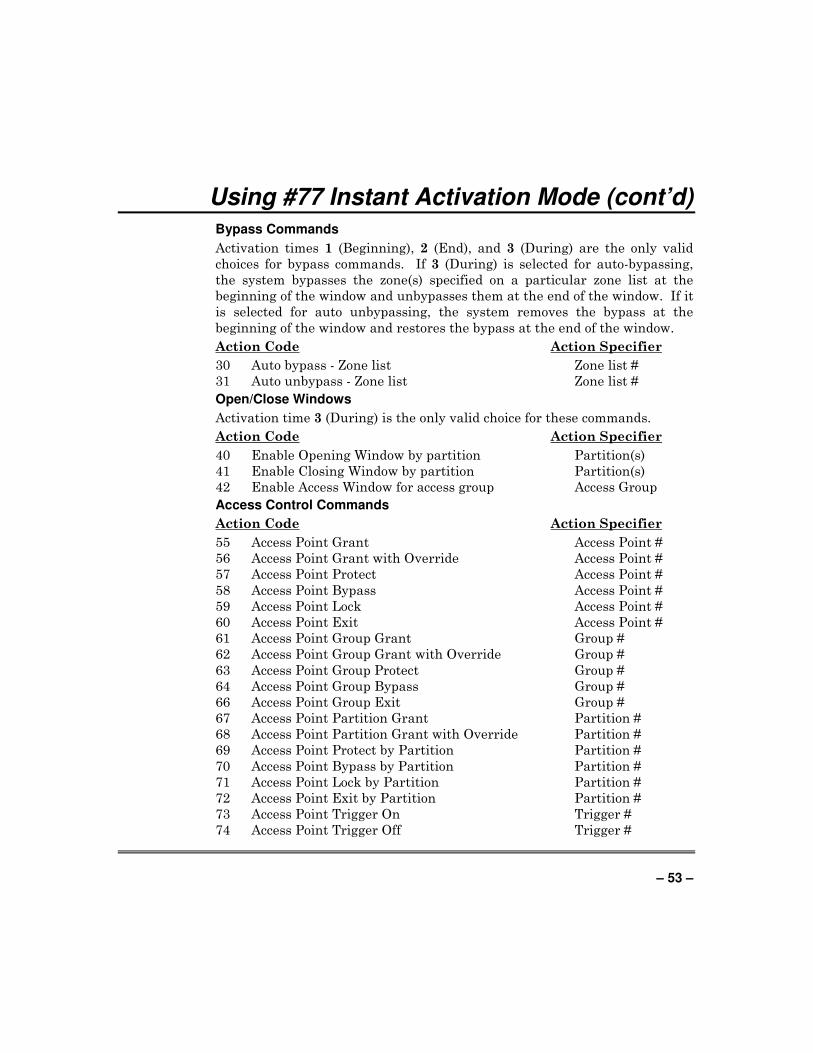
Using #77 Instant Activation Mode (cont’d) Bypass Commands
Activation times 1 (Beginning), 2 (End), and 3 (During) are the only valid
choices for bypass commands. If 3 (During) is selected for auto-bypassing,
the system bypasses the zone(s) specified on a particular zone list at the
beginning of the window and unbypasses them at the end of the window. If it
is selected for auto unbypassing, the system removes the bypass at the
beginning of the window and restores the bypass at the end of the window.
Action Code Action Specifier
30 Auto bypass - Zone list Zone list #
31 Auto unbypass - Zone list Zone list #
Open/Close Windows
Activation time 3 (During) is the only valid choice for these commands.
Action Code Action Specifier
40 Enable Opening Window by partition Partition(s)
41 Enable Closing Window by partition Partition(s)
42 Enable Access Window for access group Access Group
Access Control Commands
Action Code Action Specifier
55 Access Point Grant Access Point #
56 Access Point Grant with Override Access Point #
57 Access Point Protect Access Point #
58 Access Point Bypass Access Point #
59 Access Point Lock Access Point #
60 Access Point Exit Access Point #
61 Access Point Group Grant Group #
62 Access Point Group Grant with Override Group #
63 Access Point Group Protect Group #
64 Access Point Group Bypass Group #
66 Access Point Group Exit Group #
67 Access Point Partition Grant Partition #
68 Access Point Partition Grant with Override Partition #
69 Access Point Protect by Partition Partition #
70 Access Point Bypass by Partition Partition #
71 Access Point Lock by Partition Partition #
72 Access Point Exit by Partition Partition #
73 Access Point Trigger On Trigger #
74 Access Point Trigger Off Trigger #
– 54 –
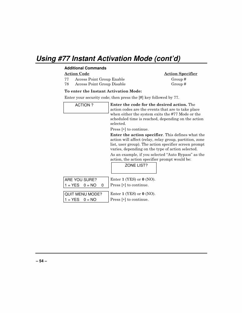
Using #77 Instant Activation Mode (cont’d) Additional Commands
Action Code Action Specifier
77 Access Point Group Enable Group #
78 Access Point Group Disable Group #
To enter the Instant Activation Mode:
Enter your security code; then press the [#] key followed by 77.
ACTION ?
Enter the code for the desired action. The
action codes are the events that are to take place
when either the system exits the #77 Mode or the
scheduled time is reached, depending on the action
selected.
Press [∗] to continue.
Enter the action specifier. This defines what the
action will affect (relay, relay group, partition, zone
list, user group). The action specifier screen prompt
varies, depending on the type of action selected.
As an example, if you selected “Auto Bypass” as the
action, the action specifier prompt would be:
ZONE LIST?
ARE YOU SURE?
1 = YES 0 = NO 0
Enter 1 (YES) or 0 (NO).
Press [∗] to continue.
QUIT MENU MODE?
1 = YES 0 = NO
Enter 1 (YES) or 0 (NO).
Press [∗] to continue.
– 55 –
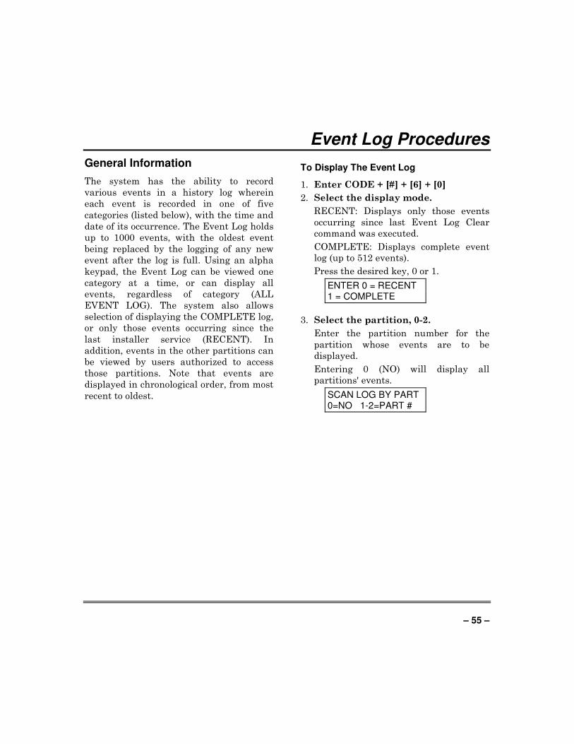
Event Log Procedures
General Information
The system has the ability to record
various events in a history log wherein
each event is recorded in one of five
categories (listed below), with the time and
date of its occurrence. The Event Log holds
up to 1000 events, with the oldest event
being replaced by the logging of any new
event after the log is full. Using an alpha
keypad, the Event Log can be viewed one
category at a time, or can display all
events, regardless of category (ALL
EVENT LOG). The system also allows
selection of displaying the COMPLETE log,
or only those events occurring since the
last installer service (RECENT). In
addition, events in the other partitions can
be viewed by users authorized to access
those partitions. Note that events are
displayed in chronological order, from most
recent to oldest.
To Display The Event Log
1. Enter CODE + [#] + [6] + [0]
2. Select the display mode.
RECENT: Displays only those events
occurring since last Event Log Clear
command was executed.
COMPLETE: Displays complete event
log (up to 512 events).
Press the desired key, 0 or 1.
ENTER 0 = RECENT 1 = COMPLETE
3. Select the partition, 0-2.
Enter the partition number for the
partition whose events are to be
displayed.
Entering 0 (NO) will display all
partitions' events.
SCAN LOG BY PART 0=NO 1-2=PART #
– 56 –
Event Logging Procedures (continued)
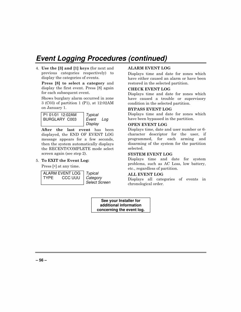
4. Use the [3] and [1] keys (for next and
previous categories respectively) to
display the categories of events.
Press [8] to select a category and
display the first event. Press [8] again
for each subsequent event.
Shows burglary alarm occurred in zone
3 (C03) of partition 1 (P1), at 12:02AM
on January 1.
P1 01/01 12:02AM BURGLARY C003
Typical Event Log Display
After the last event has been
displayed, the END OF EVENT LOG
message appears for a few seconds,
then the system automatically displays
the RECENT/COMPLETE mode select
screen again (see step 2).
5. To EXIT the Event Log:
Press [∗] at any time.
ALARM EVENT LOG TYPE CCC UUU
Typical Category Select Screen
ALARM EVENT LOG
Displays time and date for zones which
have either caused an alarm or have been
restored in the selected partition.
CHECK EVENT LOG
Displays time and date for zones which
have caused a trouble or supervisory
condition in the selected partition.
BYPASS EVENT LOG
Displays time and date for zones which
have been bypassed in the partition.
OPEN EVENT LOG
Displays time, date and user number or 6-
character descriptor for the user, if
programmed, for each arming and
disarming of the system for the partition
selected.
SYSTEM EVENT LOG
Displays time and date for system
problems, such as AC Loss, low battery,
etc., regardless of partition.
ALL EVENT LOG
Displays all categories of events in
chronological order.
See your Installer for additional information
concerning the event log.
– 57 –
Testing the System (To Be Conducted Weekly)
Using the 5 TEST Key
The TEST key puts your system into Burglary Walk Test mode, which allows each
burglary protection point to be checked for proper operation.
1. Disarm the system and close all protected windows, doors, etc. READY should be
displayed. TEST
2. Enter your security code and press the 5 key.
3. The external sounder should sound for 3 seconds and then turn off. If the sounder
does not sound, it may be due to dialer communication activity. Wait a few minutes
and try again. If the sounder still does not sound, CALL FOR SERVICE
IMMEDIATELY.
4. The keypad will sound a single beep every 15 seconds as a reminder that the system
is in Test mode. Each time a protection zone is faulted (opened); the keypad should
beep three times. If the sounder does not sound, CALL FOR SERVICE
IMMEDIATELY.
NOTES:
• No alarm reports will be sent to the central monitoring station while the system is in Test mode.
• The system will automatically exit the Test mode if there is no activity (no doors or windows are opened and closed, no motion detectors are activated, etc.) for 60 minutes. The system will beep the keypad(s) twice every 5 seconds during the last 5 minutes as a warning that it is about to exit the Test mode and return to normal operation.
Testing Your System
1. Open and close each protected door and window in turn and listen for three beeps.
Each faulted protection point should appear on the display.
2. Walk in front of any motion detectors (if used) and listen for three beeps as
movement is detected (wireless motion detectors have a 3-1/2 minute lockout
between trips). Each detector’s should appear on the display when it is activated.
3. Follow the manufacturer's instructions to test all smoke detectors to ensure that all
are functioning properly. Each detector should appear on the display when activated.
4. When all protection points have been checked, there should be no zone identification
numbers displayed. If a problem is experienced with any protection point (no
confirming sounds, no display), CALL FOR SERVICE IMMEDIATELY.
5. Turn off Test mode by entering the security code + the OFF key.
– 58 –
Fire Alarm System
Your fire alarm system (if installed) is on 24 hours a day, providing
continuous protection. In the event of an emergency, the smoke and heat
detectors automatically send signals to your Control, triggering a loud
interrupting sound from the keypad and the optional exterior sounders.
FIRE appears at your keypad and remains on until you silence the alarm.
In Case Of Fire Alarm
1. Should you become aware of a fire emergency before your detectors sense
the problem, go to your nearest keypad and manually initiate an alarm
by pressing the panic key assigned as FIRE emergency (if programmed
by the installer) and hold down for at least 2 seconds.
2. Evacuate all occupants from the premises.
3. If flames and/or smoke are present, leave the premises and notify your
local Fire Department immediately.
4. If no flames or smoke are apparent, investigate the cause of the alarm.
The descriptor of the zone(s) in alarm appears at the keypad.
Silencing a Fire Alarm
1. Silence the keypad by entering your code and pressing the OFF key.
This may or may not also silence the fire bells. A second entry may be
required, depending on system programming. To clear the display, enter
your code and press the OFF key again
2. If the keypad does not indicate a READY condition after the second OFF
sequence, press the READY key to display the zone(s) that are faulted.
Be sure to check that smoke detectors are not responding to smoke or
heat producing objects in their vicinity. Should this be the case,
eliminate the source of heat or smoke.
3. If this does not remedy the problem, there may still be smoke in the
detector. Clear it by fanning the detector for about 30 seconds.
4. You can clear the display by entering your code + the OFF key.
– 59 –
Fire Alarm System (cont’d)
Event Display Lock
If several zones produce an alarm, trouble or supervisory, the system will
display the first zone that produced an event. To display the other zone(s) in
alarm or trouble, press the [∗] key for each zone.
Fire Drill Test (Code + # + 69)
This test causes Notification Appliance Circuits to be activated for the
purpose of conducting a fire drill or a bell test. This can only be activated by
the installer or a master user from Partition 1 keypads as follows:
1. Enter the corresponding security code and press [#} + 69 (make sure the
burglary portion of the system is disarmed). Keypads will display “FIRE
DRILL ACTIVE” while the test is active.
2. The test may be stopped by entering any security code and pressing OFF.
NOTE: The system continues to monitor all 24-hour zones (fire, panic, etc.),
while this test is active, and will end the test when an alarm condition is
detected. This test should be conducted at periodic intervals as determined
by the local authority having jurisdiction.
– 60 –
Trouble Conditions
Typical Trouble Displays
The word CHECK or TRBL on the Keypad's display, accompanied by a rapid
"beeping" at the Keypad, indicates there is a trouble condition in the system.
To silence the beeping sound for trouble conditions, press any key.
• “CHECK” or “TRBL” display accompanied by a display of "CALL
SERVICE" indicates that a problem exists with the system that
eliminates some of the protection. CALL FOR SERVICE
IMMEDIATELY.
• “CHECK” or “TRBL" display accompanied by a display of one or more
zone descriptors indicate that a problem exists with those zone(s). First,
determine if the zone(s) displayed are intact (this may include Fire and
Waterflow type zones) and make them so if they are not. If the problem
has been corrected, key an OFF sequence (Code plus OFF) to clear the
“CHECK” or “TRBL” display. If the display persists, CALL FOR
SERVICE IMMEDIATELY.
• “CHECK” or “TRBL” display accompanied by a display of “6XX,” where
XX = 01-32, indicates a trouble on a supervised relay (corresponding
relay number 01-32).
• “CHECK” or “TRBL” display accompanied by a display of “8XX,” where
XX = 00-30, indicates a trouble on a peripheral device (connected to the
panel’s keypad terminals).
• “CHECK” or “TRBL” display accompanied by a display of “9XX,” where
XX = 00-99, indicates a system trouble exists (dialers, Notification
Appliance Circuits, ground fault, etc.). These zones are as follows:
970: Bell 1 Output 975: Dialer 2
971: Bell 2 Output 988: 2nd RF Receiver – not receiving signals
972: Earth Ground Fault 990: 1st RF Receiver – not receiving signals
973: J2 Trigger Output 997: Polling Loop Short
974: Dialer 1
• “SUPV” display accompanied by a display of one or more zone
descriptors indicates a problem on fire supervisory zone(s). This means
that the operation of the fire alarm system may be compromised. First,
determine if the zone(s) displayed are intact and make them so if they
are not. If the problem has been corrected, key an OFF sequence (Code
plus OFF) to clear the “SUPV” display. If the display persists, CALL
FOR SERVICE IMMEDIATELY.
– 61 –
Trouble Conditions (cont’d)
• A display of "COMM. FAILURE" at the Keypad indicates that a failure
has occurred in the telephone communication portion of your system.
CALL FOR SERVICE IMMEDIATELY.
• A display of "SYSTEM LO BAT", accompanied by a once per minute
"beeping" at the Keypad indicates that a low system battery condition
exists. CALL FOR SERVICE IMMEDIATELY.
• A display of "LO BAT" and a zone descriptor, accompanied by a once per
minute "beeping" at the Keypad indicates that a low battery condition
exists in the wireless transmitter displayed. CALL FOR SERVICE
IMMEDIATELY.
• A display of "MODEM COMM" indicates that the control is on-line with
the central station's remote computer. The control will not operate while
on-line.
• A display of “HSENS” and a zone number indicates a smoke detector
with a high sensitivity level, which may cause false alarms. CALL FOR
SERVICE IMMEDIATELY.
• A display of “LSENS” and a zone number indicates a smoke detector
with a low sensitivity level. Detectors with a low sensitivity might not
detect a smoke condition. CALL FOR SERVICE IMMEDIATELY.
Power Failure
If the message "AC LOSS" is displayed, the Keypad is operating on battery
power only. If only some lights are out on the premises, check circuit
breakers and fuses and reset or replace as necessary. CALL FOR SERVICE
IMMEDIATELY if AC power cannot be restored.
SERVICING INFORMATION
Your local HONEYWELL dealer is the person best qualified to service your
alarm system. Arranging some kind of regular service program with him is
advisable. Your local HONEYWELL dealer is:
Name:
Address:
Phone:
– 62 –
Emergency Evacuation
Establish and regularly practice a plan of escape in the event of fire. The following steps are
recommended by the National Fire Protection Association:
1. Position your detector or your interior and/or exterior sounders so that
they can be heard by all occupants.
2. Determine two means of escape from each room. One path of escape
should lead to the door that permits normal exit from the building. The
other may be a window, should your path be impassable. Station an
escape ladder at such windows if there is a long drop to the ground.
3. Sketch a floor plan of the building. Show windows, doors, stairs and
rooftops that can be used to escape. Indicate escape routes for each room.
Keep these routes free from obstruction and post copies of the escape
routes in every room.
4. Assure that all fire doors are shut while you in the building. This will
prevent deadly smoke from entering while you escape.
5. Try the door. If the door is hot, check your alternate escape route. If the
door is cool, open it cautiously. Be prepared to slam the door if smoke or
heat rushes in.
6. Where smoke is present, crawl on the ground; do not walk upright.
Smoke rises and may overcome you. Clearer air is near the floor.
7. Escape quickly; don't panic.
8. Establish a common meeting place outdoors, away from your house,
where everyone can meet and then take steps to contact the authorities
and account for those missing. Choose someone to assure that nobody
returns to the house — many die going back.
– 63 –
Maintaining Your System
Taking Care of Your System
The components of your security system are designed to be as free of
maintenance as possible. However, there are some things you can do to make
sure that your system is in reliable working condition.
1. Test your system weekly. (See TESTING THE SYSTEM and FIRE
ALARM SYSTEM sections).
2. Test the system after any alarm occurs.
Replacing Batteries in Wireless Sensors
Wireless sensors may not have been used in your security system
Each wireless sensor in your system has a 9-volt or 3-volt battery. The system
detects a low battery in any wireless sensor, including smoke detectors, the
optional personal emergency transmitter, and the optional portable wireless
keypad. (A low battery in a portable wireless keypad is detected as soon as
one of its keys is pressed, and the keypad will display 00.)
Alkaline batteries provide a minimum of 1 year of operation, and in most
units and applications, provide 2–4 years of service. Actual battery life will
depend on the environment in which the sensor is used, the number of signals
that the transmitter in the sensor has had to send, and the specific type of
sensor. Factors such as humidity, high or low temperatures or large swings
in temperature, may all lead to the reduction of actual battery life in an
installation.
If you have a low battery in a wireless sensor, a low battery message
is displayed on the keypad.
In addition, a battery-operated smoke detector with a low battery also emits
a single "chirp" sound once approximately every 20-30 seconds, identifying
itself as the smoke detector with the weak battery. If you do not replace a
smoke detector's low battery, the smoke detector may sound continuously, as
if there were a fire alarm.
NOTE: The low battery message comes on as a warning that battery
replacement in indicated sensor(s) is due within 30 days. In the meantime,
the sensor(s) causing the low battery indication is still fully operational.
IMPORTANT: Use only batteries recommended by your installer as
replacement.
– 64 –
Maintaining Your System (cont’d)
Silencing Low Battery Warning Tones at the Keypad
The keypad’s warning tones can be silenced by performing an OFF sequence
(code plus OFF key), but the Keypad's low battery message display will
remain on as a reminder that you have a low battery condition in one or more
of your sensors. When you replace the weak battery with a fresh one, the
sensor will send a "good battery" signal to the control as soon as the sensor is
activated (opening/closing of door, window, etc.), causing the low battery
display to turn off. If the sensor is not activated, the display will
automatically clear within approximately 1 hour.
Routine Care
• Treat the components of your security system as you would any other
electrical equipment. Do not slam sensor-protected doors or windows.
• Keep dust from accumulating on the keypad and all protective sensors,
particularly on motion sensors and smoke detectors.
• The keypad and sensors should be cleaned carefully with a dry soft cloth.
Do not spray water or any other fluid on the units.
NOTE: It is important that your system is tested periodically to
insure proper protection. This includes testing the fire alarm
portion of your system. See TESTING THE SYSTEM and FIRE
ALARM SYSTEM sections for the testing procedures.
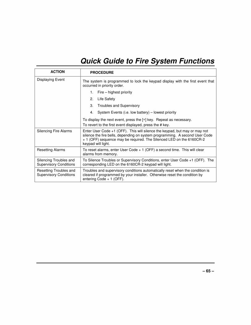
– 65 –
Quick Guide to Fire System Functions
ACTION PROCEDURE
Displaying Event The system is programmed to lock the keypad display with the first event that occurred in priority order.
1. Fire – highest priority
2. Life Safety
3. Troubles and Supervisory
4. System Events (i.e. low battery) – lowest priority
To display the next event, press the [∗] key. Repeat as necessary.
To revert to the first event displayed, press the # key.
Silencing Fire Alarms Enter User Code +1 (OFF). This will silence the keypad, but may or may not silence the fire bells, depending on system programming. A second User Code + 1 (OFF) sequence may be required. The Silenced LED on the 6160CR-2 keypad will light.
Resetting Alarms To reset alarms, enter User Code + 1 (OFF) a second time. This will clear alarms from memory.
Silencing Troubles and Supervisory Conditions
To Silence Troubles or Supervisory Conditions, enter User Code +1 (OFF). The corresponding LED on the 6160CR-2 keypad will light.
Resetting Troubles and Supervisory Conditions
Troubles and supervisory conditions automatically reset when the condition is cleared if programmed by your installer. Otherwise reset the condition by entering Code + 1 (OFF).

– 66 –
Quick Guide to Burglary System Functions FUNCTION PROCEDURE COMMENTS
Check Zones Press [∗]. To view faulted zones when is system not ready
Display All Descriptors
Press and hold [∗] for 5 seconds. Displays all alpha descriptors programmed by installer.
Arm System Enter code. Press arming key desired (AWAY,
STAY, INSTANT, MAXIMUM).
Arms system in mode selected.
NOTE: After pressing the STAY or INSTANT arming key, enter 1, 2 or 3 to arm in the desired STAY or INSTANT mode.
Disarm System Enter code. Press OFF [1]. Disarms system and silences alarms.
Bypass Zones Enter code. Press BYPASS [6]. Enter zone numbers to be
bypassed (use 3-digit entries).
Press [∗] + [∗].
Bypassed zones are unprotected and will not cause an alarm if violated.
Quick Bypass Enter code. Press BYPASS [6]. Press [#].
Bypasses all faulted zones automatically.
Group Bypass Enter code. Press BYPASS [6]. Press [Q]. Enter Group Number
(01-15)
Bypasses all zones assigned to the group.
Chime Mode Enter code. Press CHIME [9]. Keypad will sound if doors or windows are violated while system disarmed.
Test Mode Enter code. Press TEST [5] Activates alarm sounder and allows sensors to be tested.
View Messages Press and hold [0] for at least 5 seconds.
Message from central station will appear.
View User Capabilities
Enter user's code. Press [∗] + [∗]. Displays partitions and authority levels assigned to the user.
GOTO Partition Enter security code. Press [∗]. Enter partition number (1-2). 0 returns to default partition.
Allows a user at one keypad to perform functions in another partition, if that user is authorized to do so.
Self-Help Press and hold any function key for at least 5 seconds.
Will display abbreviated instructions for the key pressed.
Add a User Enter master/manager code. Press CODE [8]. Enter new user's user number. Enter code for that user. Enter authority for that user in this
partition (1-5). Follow prompts, 1=Yes, 0=No.
Master and Manager level users can add users to the system, each with its own code and authority level.
Change a User's Code
Enter master/manager code. Press CODE [8]. Enter user's 2-digit number. Enter new code for that user. Press 0 (No) at prompt.
Master and Manager level users can change their own or other users' codes.
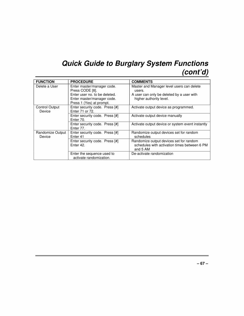
– 67 –
Quick Guide to Burglary System Functions (cont’d)
FUNCTION PROCEDURE COMMENTS
Delete a User Enter master/manager code. Press CODE [8]. Enter user no. to be deleted. Enter master/manager code. Press 1 (Yes) at prompt.
Master and Manager level users can delete users.
A user can only be deleted by a user with higher authority level.
Control Output Device
Enter security code. Press [#] Enter 71 or 72.
Activate output device as programmed.
Enter security code. Press [#] Enter 70.
Activate output device manually
Enter security code. Press [#] Enter 77.
Activate output device or system event instantly
Randomize Output Device
Enter security code. Press [#] Enter 41
Randomize output devices set for random schedules
Enter security code. Press [#] Enter 42.
Randomize output devices set for random schedules with activation times between 6 PM and 5 AM
Enter the sequence used to activate randomization.
De-activate randomization
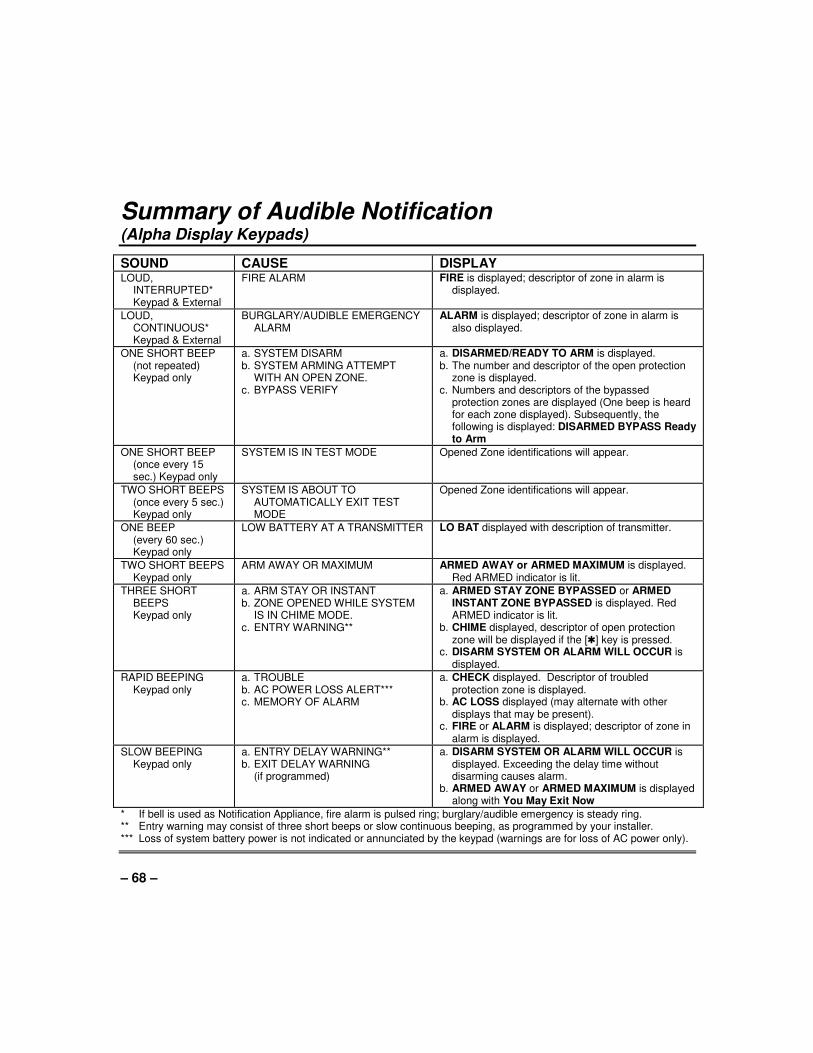
– 68 –
Summary of Audible Notification (Alpha Display Keypads)
SOUND CAUSE DISPLAY LOUD,
INTERRUPTED* Keypad & External
FIRE ALARM FIRE is displayed; descriptor of zone in alarm is displayed.
LOUD, CONTINUOUS*
Keypad & External
BURGLARY/AUDIBLE EMERGENCY ALARM
ALARM is displayed; descriptor of zone in alarm is also displayed.
ONE SHORT BEEP (not repeated)
Keypad only
a. SYSTEM DISARM b. SYSTEM ARMING ATTEMPT
WITH AN OPEN ZONE. c. BYPASS VERIFY
a. DISARMED/READY TO ARM is displayed. b. The number and descriptor of the open protection
zone is displayed. c. Numbers and descriptors of the bypassed
protection zones are displayed (One beep is heard for each zone displayed). Subsequently, the following is displayed: DISARMED BYPASS Ready to Arm
ONE SHORT BEEP (once every 15
sec.) Keypad only
SYSTEM IS IN TEST MODE Opened Zone identifications will appear.
TWO SHORT BEEPS (once every 5 sec.)
Keypad only
SYSTEM IS ABOUT TO AUTOMATICALLY EXIT TEST MODE
Opened Zone identifications will appear.
ONE BEEP (every 60 sec.)
Keypad only
LOW BATTERY AT A TRANSMITTER LO BAT displayed with description of transmitter.
TWO SHORT BEEPS Keypad only
ARM AWAY OR MAXIMUM ARMED AWAY or ARMED MAXIMUM is displayed. Red ARMED indicator is lit.
THREE SHORT BEEPS
Keypad only
a. ARM STAY OR INSTANT b. ZONE OPENED WHILE SYSTEM
IS IN CHIME MODE. c. ENTRY WARNING**
a. ARMED STAY ZONE BYPASSED or ARMED INSTANT ZONE BYPASSED is displayed. Red ARMED indicator is lit.
b. CHIME displayed, descriptor of open protection zone will be displayed if the [Q] key is pressed.
c. DISARM SYSTEM OR ALARM WILL OCCUR is displayed.
RAPID BEEPING Keypad only
a. TROUBLE b. AC POWER LOSS ALERT*** c. MEMORY OF ALARM
a. CHECK displayed. Descriptor of troubled protection zone is displayed.
b. AC LOSS displayed (may alternate with other displays that may be present).
c. FIRE or ALARM is displayed; descriptor of zone in alarm is displayed.
SLOW BEEPING Keypad only
a. ENTRY DELAY WARNING** b. EXIT DELAY WARNING (if programmed)
a. DISARM SYSTEM OR ALARM WILL OCCUR is displayed. Exceeding the delay time without disarming causes alarm.
b. ARMED AWAY or ARMED MAXIMUM is displayed along with You May Exit Now
* If bell is used as Notification Appliance, fire alarm is pulsed ring; burglary/audible emergency is steady ring. ** Entry warning may consist of three short beeps or slow continuous beeping, as programmed by your installer. *** Loss of system battery power is not indicated or annunciated by the keypad (warnings are for loss of AC power only).
– 69 –
FEDERAL COMMUNICATIONS COMMISSION STATEMENTS
The user shall not make any changes or modifications to the equipment unless authorized by the Installation Instructions or User's Manual. Unauthorized changes or modifications could void the user's authority to operate the equipment.
FCC CLASS B STATEMENT
This equipment has been tested to FCC requirements and has been found acceptable for use. The FCC requires the following statement for your information:
This equipment generates and uses radio frequency energy and if not installed and used properly, that is, in strict accordance with the manufacturer's instructions, may cause interference to radio and television reception. It has been type tested and found to comply with the limits for a Class B computing device in accordance with the specifications in Part 15 of FCC Rules, which are designed to provide reasonable protection against such interference in a residential installation. However, there is no guarantee that interference will not occur in a particular installation. If this equipment does cause interference to radio or television reception, which can be determined by turning the equipment off and on, the user is encouraged to try to correct the interference by one or more of the following measures:
• If using an indoor antenna, have a quality outdoor antenna installed.
• Reorient the receiving antenna until interference is reduced or eliminated.
• Move the radio or television receiver away from the receiver/control.
• Move the antenna leads away from any wire runs to the receiver/control.
• Plug the receiver/control into a different outlet so that it and the radio or television receiver are on different branch circuits.
• Consult the dealer or an experienced radio/TV technician for help.
INDUSTRY CANADA CLASS B STATEMENT
This Class B digital apparatus complies with Canadian ICES-003.
Cet appareil numérique de la classe B est conforme à la norme NMB-003 du Canada.
FCC / IC STATEMENT
This device complies with Part 15 of the FCC Rules, and RSS 210 of IC. Operation is subject to the following two conditions: (1) This device may not cause harmful interference (2) This device must accept any interference received, including interference that may cause undesired operation.
Cet appareil est conforme à la partie 15 des règles de la FCC & de RSS 210 des Industries Canada. Son fonctionnement est soumis aux conditions suivantes: (1) Cet appareil ne doit pas causer d' interferences nuisibles. (2) Cet appareil doit accepter toute interference reçue y compris les interferences causant une reception indésirable.
IN THE EVENT OF TELEPHONE OPERATIONAL PROBLEMS In the event of telephone operational problems, disconnect the control by removing the plug from the RJ31X (CA38A in Canada) telephone wall jack. We recommend that your certified installer demonstrate disconnecting the phones on installation of the system. Do not disconnect the phone connection inside the control/communicator. Doing so will result in the loss of your phone lines. If the regular phone works correctly after the control/communicator has been disconnected from the phone lines, the control/communicator has a problem and should be returned for repair. If upon disconnection of the control/communicator, there is still a problem on the line, notify the telephone company that they have a problem and request prompt repair service. The user may not under any circumstances (in or out of warranty) attempt any service or repairs to the system. It must be returned to the factory or an authorized service agency for all repairs.
– 70 –
“FEDERAL COMMUNICATIONS COMMISSION (FCC) Part 68 NOTICE
This equipment complies with Part 68 of the FCC rules. On the front cover of this equipment is a label that contains, among other information, the FCC registration number and ringer equivalence number (REN) for this equipment. If requested, this information must be provided to the telephone company.
This equipment uses the following jacks:
An RJ31X is used to connect this equipment to the telephone network.
The REN is used to determine the quantity of devices which may be connected to the telephone line. Excessive RENs on the telephone line may result in the devices not ringing in response to an incoming call. In most, but not all areas, the sum of the RENs should not exceed five (5.0). To be certain of the number of devices that may be connected to the line, as determined by the total RENs, contact the telephone company to determine the maximum REN for the calling area.
If this equipment causes harm to the telephone network, the telephone company will notify you in advance that temporary discontinuance of service may be required. If advance notice is not practical, the telephone company will notify the customer as soon as possible. Also, you will be advised of your right to file a complaint with the FCC if you believe necessary.
The telephone company may make changes in its facilities, equipment, operations, or procedures that could affect the operation of the equipment. If this happens, the telephone company will provide advance notice in order for you to make the necessary modifications in order to maintain uninterrupted service.
If trouble is experienced with this equipment, please contact the manufacturer for repair and warranty information. If the trouble is causing harm to the telephone network, the telephone company may request you remove the equipment from the network until the problem is resolved.
There are no user serviceable components in this product, and all necessary repairs must be made by the manufacturer. Other repair methods may invalidate the FCC registration on this product.
This equipment cannot be used on telephone company-provided coin service. Connection to Party Line Service is subject to state tariffs.
This equipment is hearing-aid compatible.
When programming or making test calls to an emergency number, briefly explain to the dispatcher the reason for the call. Perform such activities in the off-peak hours; such as early morning or late evening.
– 71 –
CANADIAN DEPARTMENT OF COMMUNICATIONS (DOC) STATEMENT
NOTICE
The Canadian Department of Communications label identifies certified equipment. This certification means that the equipment meets certain telecommunications network protective, operational and safety requirements. The Department does not guarantee the equipment will operate to the user’s satisfaction.
Before installing this equipment, users should ensure that it is permissible to be connected to the facilities of the local telecommunications company. The equipment must also be installed using an acceptable method of connection. In some cases, the company’s inside wiring associated with a single line individual service may be extended by means of certified connector assembly (telephone extension cord). The customer should be aware that compliance with the above conditions may not prevent degradation of service in some situations.
Repairs to certified equipment should be made by an authorized Canadian maintenance facility designated by the supplier. Any repairs or alterations made by the user to this equipment, or equipment malfunctions, may give the telecommunications company cause to request the user to disconnect the equipment.
Users should ensure for their own protection that the electrical ground connections of the power utility, telephone lines and internal metallic water pipe system, if present, are connected together. This precaution may be particularly important in rural areas.
Caution: User should not attempt to make such connections themselves, but should contact the appropriate electric inspection authority, or electrician, as appropriate.
The Load Number (LN) assigned to each terminal device denotes the percentage of the total load to be connected to a telephone loop which is used by the device, to prevent overloading. The termination on a loop may consist of any combination of devices subject only to the requirement that the total of the Load Numbers of all the devices does not exceed 100.
AVIS
L’étiquette du ministère des Communications du Canada identifie le matériel homologué. Cette étiquette certifie que le matériel est conforme à certaines normes de protection, d’exploitation et de sécurité des réseaux de télécommunications. Le ministère n’assure toutefois pas que le matériel fonctionnera à la satisfaction de l’utilisateur.
Avant d’installer ce matériel, l’utilisateur doit s’assurer qu’il est permis de le raccorder aux installations de l’entreprise locale de télécommunications. Le matériel doit également être installé en suivant une méthode acceptée de raccordement. Dans certains cas, les fils intérieurs de l’entreprise utilisés pour un service individuel à la ligne unique peuvent être prolongés au moyen d’un dispositif homologué de raccordement (cordon prolongateur téléphonique interne). L’abonné ne doit pas oublier qu’il est possible que la conformité aux conditions énoncées ci-dessus n’empèchet pas la dégradation du service dans certaines situations. Actuellement, les entreprises de télécommunications ne permettent pas que l’on raccorde leur matériel aux prises d’abonnés, sauf dans les cas precis prévus par les tarifs particuliers de ces entreprises.
Les réparations du matériel homologué doivent être effectuées pas un centre d’entretien canadien autorisé désigné par le fournisseur. La compagnie de télécommunications peut demander à l’utilisateur de débrancher un appareil à la suite de réparations ou de modifications effectuées par l’utilisateur ou à cause de mauvais fonctionnement.
Pour sa propre protection, l’utilisateur doit s’assurer que tous les fils de mise en terre de la source d’énergie électrique, des lignes téléphoniques de réseau de conduites d’eau s’il y en a, soient raccordés ensemble. Cette précaution est particulièrement importante dans les régions rurales.
Avertissement: L’utilisateur ne doit pas tenter de faire ces raccordements lui-même; il doit avoir recours à un service d’inspection des installations électriques, ou à un électricien, selon le cas.
L’indice de charge (IC) assigné à chaque dispositif terminal pour éviter toute surcharge indique le pourcentage de la charge totale qui peut être raccordé à un circuit téléphonique bouclé utilisé par ce dispositif. La terminaison du circuit bouclé peut être constituée de n’importe quelle combinaison de dispositifs, pourvu que la somme des indices de charge de l’ensemble des dispositifs ne dépasse pas 100.
– 72 –
WARNING! THE LIMITATIONS OF THIS ALARM SYSTEM
While this system is an advanced design security system, it does not offer guaranteed protection against burglary or fire or other emergency. Any alarm system, whether commercial or residential, is subject to compromise or failure to warn for a variety of reasons. For example: • Intruders may gain access through unprotected openings or have the technical sophistication to bypass an alarm sensor
or disconnect an alarm warning device. • Intrusion detectors (e.g. passive infrared detectors), smoke detectors, and many other sensing devices will not work
without power. Battery operated devices will not work without batteries, with dead batteries, or if the batteries are not put in properly. Devices powered solely by AC will not work if their AC power supply is cut off for any reason, however briefly.
• Signals sent by wireless transmitters may be blocked or reflected by metal before they reach the alarm receiver. Even if the signal path has been recently checked during a weekly test, blockage can occur if a metal object is moved into the path.
• A user may not be able to reach a panic or emergency button quickly enough. • While smoke detectors have played a key role in reducing residential fire deaths in the United States, they may not
activate or provide early warning for a variety of reasons in as many as 35% of all fires, according to data published by the Federal Emergency Management Agency. Some of the reasons smoke detectors used in conjunction with this System may not work are as follows. Smoke detectors may have been improperly installed and positioned. Smoke detectors may not sense fires that start where smoke cannot reach the detectors, such as in chimneys, in walls, or roofs, or on the other side of closed doors. Smoke detectors also may not sense a fire on another level of a residence or building. A second floor detector, for example, may not sense a first floor or basement fire. Moreover, smoke detectors have sensing limitations. No smoke detector can sense every kind of fire every time. In general, detectors may not always warn about fires caused by carelessness and safety hazards like smoking in bed, violent explosions, escaping gas, improper storage of flammable materials, overloaded electrical circuits, children playing with matches, or arson. Depending upon the nature of the fire and/or the locations of the smoke detectors, the detector, even if it operates as anticipated, may not provide sufficient warning to allow all occupants to escape in time to prevent injury or death.
• Passive Infrared Motion Detectors can only detect intrusion within the designed ranges as diagrammed in their installation manual. Passive Infrared Detectors do not provide volumetric area protection. They do create multiple beams of protection, and intrusion can only be detected in unobstructed areas covered by those beams. They cannot detect motion or intrusion that takes place behind walls, ceilings, floors, closed doors, glass partitions, glass doors, or windows. Mechanical tampering, masking, painting or spraying of any material on the mirrors, windows or any part of the optical system can reduce their detection ability. Passive Infrared Detectors sense changes in temperature; however, as the ambient temperature of protected area approaches the temperature range of 90° to 105°F, the detection performance can decrease.
• Alarm warning devices such as sirens, bells or horns may not alert people or wake up sleepers if they are located on the other side of closed or partly open doors. If warning devices sound on a different level of the residence from the bedrooms, then they are less likely to waken or alert people inside the bedrooms. Even persons who are awake may not hear the warning if the alarm is muffled from a stereo, radio, air conditioner or other appliance, or by passing traffic. Finally, alarm warning devices, however loud, may not warn hearing-impaired people or waken deep sleepers.
• Telephone lines needed to transmit alarm signals from a premises to a central monitoring station may be out of service or temporarily out of service. Telephone lines are also subject to compromise by sophisticated intruders.
• Even if the system responds to the emergency as intended, however, occupants may have insufficient time to protect themselves from the emergency situation. In the case of a monitored alarm system, authorities may not respond appropriately.
• This equipment, like other electrical devices, is subject to component failure. Even though this equipment is designed to last as long as 10 years, the electronic components could fail at any time.
The most common cause of an alarm system not functioning when an intrusion or fire occurs is inadequate maintenance. This alarm system should be tested weekly to make sure all sensors and transmitters are working properly. Installing an alarm system may make one eligible for lower insurance rates, but an alarm system is not a substitute for insurance. Homeowners, property owners and renters should continue to act prudently in protecting themselves and continue to insure their lives and property. We continue to develop new and improved protection devices. Users of alarm systems owe it to themselves and their loved ones to learn about these developments.
– 73 –
Index
#70 command ........................................ 45 AC Loss ................................................. 61 Access Another Partition .................... 23 Access Control Commands ................... 53 Action Code .......................................... 52 Action Specifier ................................... 52 Add a User ............................................ 19 ADD NEW USER ................................... 21 Add User Code ...................................... 18 Ademco Dealer ...................................... 61 Alarm ....................................................... 7 Alkaline batteries ................................... 63 Alpha Keypads....................................... 10 Arm/Disarm Commands ........................ 52 Armed .................................................. 6, 7 ARMED INDICATOR ............................ 14 Audible Emergency ............................... 43 Audible Signals ...................................... 68 Authority Level ....................................... 16 Authority Levels ............................... 17, 18 Auto-STAY Arming ................................ 34 Away .................................................. 6, 23 AWAY .................................................... 40 AWAY mode .......................................... 36 battery life .............................................. 63 Burglary ................................................... 5 Burglary Protection .............................. 6, 7 Bypass Commands ............................... 53 Bypass Zones ........................................ 30 Bypassing ............................................. 30 Call Service ............................................ 60 Change a User's Code ......................... 21 Change User Code ................................ 18 CHECK .................................................. 60 Chime ................................................ 6, 41 Closing Time .......................................... 46 Comm. Failure ....................................... 61 Common Lobby ..................................... 26 Delaying Closing Time ........................ 46 Delete a User ........................................ 22
Delete User Code .................................. 18 Descriptors ............................................. 29 Device Timers ................................... 8, 49 Disarm .................................................... 39 DOC ....................................................... 71 Duress .................................................... 17 Duress Code ......................................... 16 Emergency ............................................... 5 Entry Delay............................................. 15 Entry/Exit .................................................. 6 Event Display Lock ................................ 59 Event Log Procedures ........................... 55 Exit Delay ............................................... 15 Exit User Edit Mode ............................. 18 Fire ..................................................... 5, 43 fire alarm ................................................ 58 Fire Drill Active ....................................... 59 Fire Drill Test .......................................... 59 Fire Protection .......................................... 6 GLOBAL ARM ........................................ 20 Global Arming ........................................ 23 Goto ....................................................... 20 GOTO ..................................................... 23 GOTO Command ..................................... 8 Group Bypass ........................................ 32 HSENS ................................................... 61 Instant ................................................ 6, 23 INSTANT ................................................ 15 INSTANT mode ...................................... 35 Keypad ..................................................... 5 Keypad back lighting .............................. 10 Keypads ................................................. 10 Keyswitch ............................................... 40 LO Bat .................................................... 61 Low Battery ............................................ 63 Low Battery Warning ........................... 64 LSENS ................................................... 61 Manager ................................................. 17 Master .................................................... 17 Master Keypad ................................... 8, 24
– 74 –
Maximum ............................................ 6, 23 MAXIMUM .............................................. 15 MAXIMUM mode .................................... 37 Memory of Alarm .............................. 7, 39 Messages ............................................... 42 Modem Comm ........................................ 61 MULTI-ACCESS ..................................... 20 Not Ready............................................... 28 Off ........................................................... 23 OFF ........................................................ 39 Open Zones ........................................... 28 Open/Close Schedules ........................ 46 Open/Close Windows ............................. 53 Operator A .............................................. 17 Operator B .............................................. 17 Operator C .............................................. 17 OUTPUT TIMER .................................... 49 Panic Keys ............................................ 43 PANIC KEYS.......................................... 14 Partitioned Security System ..................... 5 Partitioned System ................................... 5 Personal Emergency .............................. 43 POWER/READY INDICATOR ............... 14 Quick Arm ............................................... 14 Quick Arming ........................................ 16 Quick Bypass ........................................ 31 Quick Exit ............................................... 38 Quick Guide ................................ 65, 66, 67 Randomize Output Devices .................... 51 Ready ..................................................... 28 READY ................................................... 41 Ready Key .............................................. 28 Relay commands .................................... 52
Relay Menu Mode ................................ 45 Replacing Batteries ............................. 63 RF BUTTON .......................................... 19 Routine Care ........................................ 64 Schedules .......................................... 7, 46 Security Code ........................................ 16 Security Codes ...................................... 16 Sensing Devices ...................................... 6 Silencing A Fire Alarm ........................... 58 Silent Emergency ................................... 43 Smoke Detectors ................................... 57 Stay .................................................... 6, 23 STAY...................................................... 40 STAY mode ........................................... 33 System LO Bat ....................................... 61 System Overview ..................................... 5 Temporary Schedules ...................... 46, 47 Temporary Users ................................... 19 Test Key ................................................. 57 Test mode .............................................. 57 Testing Your System ............................. 57 Time Window ......................................... 46 TRBL ..................................................... 60 Trouble Condition .................................. 60 UNABLE TO ARM LOBBY .................... 26 User Edit Mode ...................................... 18 User Numbers ........................................ 16 User's Instructions ................................... 9 Using #77 Instant Activation Mode ........ 52 Wireless Sensor ..................................... 63 Zone Bypassed ...................................... 33 Zone Descriptors ................................... 29 Zones ...................................................... 6
TWO YEAR LIMITED WARRANTY
Honeywell International Inc., acting through its Security & Communications business (“Seller”), 2 Corporate Center Drive, Melville, New York 11747 warrants its products to be free from defects in materials and workmanship under normal use and service, normal wear and tear excepted, for 24 months from the manufacture date code; provided, however, that in the event the Buyer presents a proper invoice relating to the purchased product and such invoice bears a date later than the manufacture date, then Seller may at its discretion, reflect the warranty period as commencing at invoice date. Except as required by law, this Limited Warranty is only made to Buyer and may not be transferred to any third party. During the applicable warranty period, Seller will repair or replace, at its sole option and as the exclusive remedy hereunder, free of charge, any defective products. Seller shall have no obligation under this Limited Warranty or otherwise if the product: (i) is improperly installed, applied or maintained; (ii) installed outside of stated operating parameters, altered or improperly serviced or repaired by anyone other
than the Seller/Seller’s Authorized Service/Repair Center; (iii) damage is caused by outside natural occurrences, such as lightning, power surges, fire, floods, acts of
nature, or the like; or (iv) defects result from unauthorized modification, misuse, vandalism, alterations of serial numbers, other causes
unrelated to defective materials or workmanship, or failures related to batteries of any type used in connection with the products sold hereunder.
Exceptions to Warranty With Respect to Honeywell Products listed below: Hardwire Contacts and PIRs – Seller warrants parts for hardwire contacts and PIRs in accordance with the terms of the above limited warranty for a period of five (5) years from the manufacture date code. EXCLUSION OF WARRANTIES, LIMITATION OF LIABILITY THERE ARE NO WARRANTIES OR CONDITIONS, EXPRESS OR IMPLIED, OF MERCHANTABILITY, OR FITNESS FOR A PARTICULAR PURPOSE OR OTHERWISE, WHICH EXTEND BEYOND THE DESCRIPTION ON THE FACE HEREOF. TO THE FULLEST EXTENT PERMITTED BY LAW, IN NO CASE SHALL SELLER BE LIABLE TO ANYONE FOR ANY (i) CONSEQUENTIAL, INCIDENTAL, INDIRECT, SPECIAL, OR PUNITIVE DAMAGES ARISING OUT OF OR RELATING IN ANY WAY TO THE PRODUCT AND/OR FOR BREACH OF THIS OR ANY OTHER WARRANTY OR CONDITION, EXPRESS OR IMPLIED, OR UPON ANY OTHER BASIS OF LIABILITY WHATSOEVER, EVEN IF THE LOSS OR DAMAGE IS CAUSED BY SELLER’S OWN NEGLIGENCE OR FAULT AND EVEN IF SELLER HAS BEEN ADVISED OF THE POSSIBILITY OF SUCH LOSSES OR DAMAGES. Any product description (whether in writing or made orally by Seller or Seller’s agents), specifications, samples, models, bulletin, drawings, diagrams, engineering sheets or similar materials used in connection with the Buyer’s order are for the sole purpose of identifying the Seller’s products and shall not be construed as an express warranty or condition. Any suggestions by Seller or Seller’s agents regarding use, applications, or suitability of the products shall not be construed as an express warranty or condition unless confirmed to be such in writing by Seller. Seller does not represent that the products it sells may not be compromised or circumvented; that the products will prevent any personal injury or property loss by burglary, robbery, fire or otherwise, or that the products will in all cases provide adequate warning or protection. Buyer understands that a properly installed and maintained alarm may only reduce the risk of a burglary, robbery or fire without warning, but it is not insurance or a guarantee that such will not occur or will not cause or lead to personal injury or property loss. CONSEQUENTLY, SELLER SHALL HAVE NO LIABILITY FOR ANY PERSONAL INJURY, PROPERTY DAMAGE OR OTHER LOSS BASED ON ANY CLAIM AT ALL INCLUDING A CLAIM THE PRODUCT FAILED TO GIVE WARNING. However, if Seller is held liable whether directly or indirectly for any loss or damage with respect to the products it sells, regardless of cause or origin, its maximum liability shall not in any case exceed the purchase price of the product, which shall be fixed as liquidated damages and not as a penalty, and shall be the complete and exclusive remedy against the Seller. Should your product become defective during the warranty, please contact your installer to facilitate repair or replacement with Seller pursuant to the terms hereof. Seller reserves the right to replace any defective product under warranty with new, refurbished, or remanufactured product.

NOTES

NOTES

NOTES

NOTES

2 Corporate Center Drive, Suite 100P.O. Box 9040, Melville, NY 11747
Copyright © 2012 Honeywell International Inc.
Ê800-11045tŠ 800-11045 2/12 Rev. C