Embed Size (px)
Citation preview
ADEMCO VISTA SERIES
VISTA-21iP / VISTA-21iPSIA Security Systems
Programming Guide
K14488PRV1 7/08 Rev. B
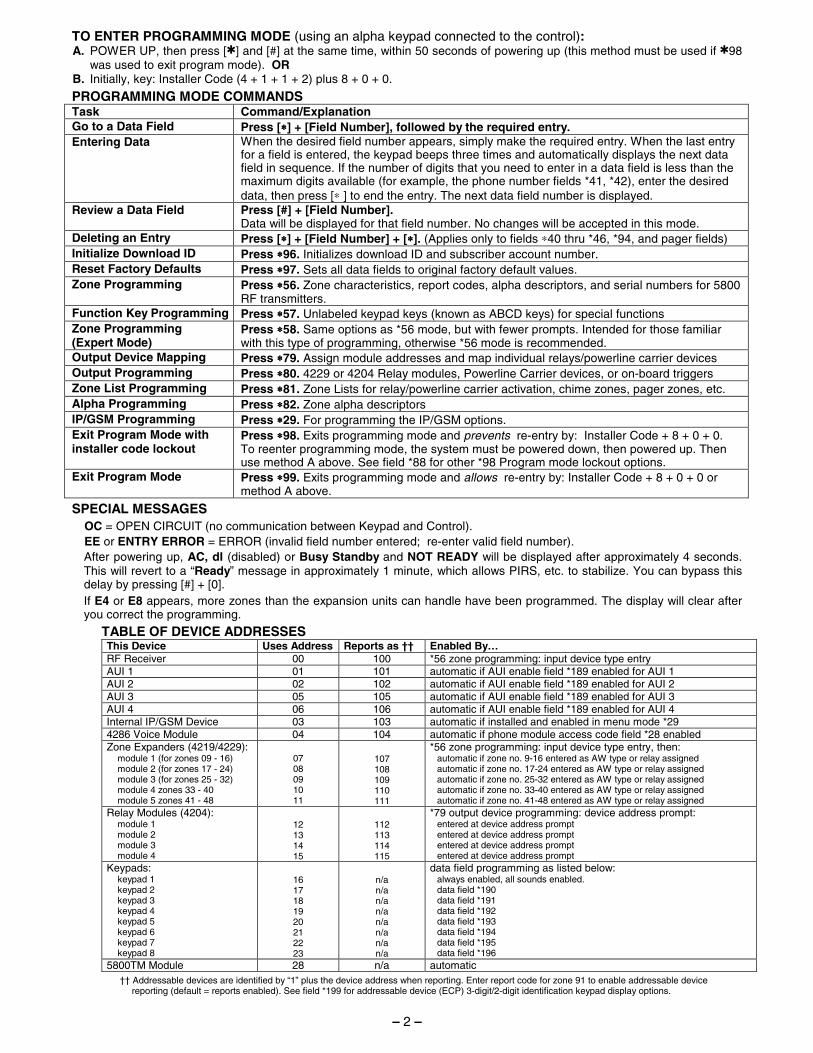
TO ENTER PROGRAMMING MODE (using an alpha keypad connected to the control): A. POWER UP, then press [✱] and [#] at the same time, within 50 seconds of powering up (this method must be used if ✱98
was used to exit program mode). OR B. Initially, key: Installer Code (4 + 1 + 1 + 2) plus 8 + 0 + 0.
PROGRAMMING MODE COMMANDS Task Command/Explanation Go to a Data Field Press [∗∗∗∗] + [Field Number], followed by the required entry. Entering Data When the desired field number appears, simply make the required entry. When the last entry
for a field is entered, the keypad beeps three times and automatically displays the next data field in sequence. If the number of digits that you need to enter in a data field is less than the maximum digits available (for example, the phone number fields *41, *42), enter the desired data, then press [∗ ] to end the entry. The next data field number is displayed.
Review a Data Field Press [#] + [Field Number]. Data will be displayed for that field number. No changes will be accepted in this mode.
Deleting an Entry Press [∗∗∗∗] + [Field Number] + [∗∗∗∗]. (Applies only to fields ∗40 thru *46, *94, and pager fields) Initialize Download ID Press ∗∗∗∗96. Initializes download ID and subscriber account number. Reset Factory Defaults Press ∗∗∗∗97. Sets all data fields to original factory default values. Zone Programming Press ∗∗∗∗56. Zone characteristics, report codes, alpha descriptors, and serial numbers for 5800
RF transmitters. Function Key Programming Press ∗∗∗∗57. Unlabeled keypad keys (known as ABCD keys) for special functions Zone Programming (Expert Mode)
Press ∗∗∗∗58. Same options as *56 mode, but with fewer prompts. Intended for those familiar with this type of programming, otherwise *56 mode is recommended.
Output Device Mapping Press ∗∗∗∗79. Assign module addresses and map individual relays/powerline carrier devices Output Programming Press ∗∗∗∗80. 4229 or 4204 Relay modules, Powerline Carrier devices, or on-board triggers Zone List Programming Press ∗∗∗∗81. Zone Lists for relay/powerline carrier activation, chime zones, pager zones, etc. Alpha Programming Press ∗∗∗∗82. Zone alpha descriptors IP/GSM Programming Press ∗∗∗∗29. For programming the IP/GSM options. Exit Program Mode with installer code lockout
Press ∗∗∗∗98. Exits programming mode and prevents re-entry by: Installer Code + 8 + 0 + 0. To reenter programming mode, the system must be powered down, then powered up. Then use method A above. See field *88 for other *98 Program mode lockout options.
Exit Program Mode Press ∗∗∗∗99. Exits programming mode and allows re-entry by: Installer Code + 8 + 0 + 0 or method A above.
SPECIAL MESSAGES OC = OPEN CIRCUIT (no communication between Keypad and Control). EE or ENTRY ERROR = ERROR (invalid field number entered; re-enter valid field number). After powering up, AC, dI (disabled) or Busy Standby and NOT READY will be displayed after approximately 4 seconds. This will revert to a “Ready” message in approximately 1 minute, which allows PIRS, etc. to stabilize. You can bypass this delay by pressing [#] + [0]. If E4 or E8 appears, more zones than the expansion units can handle have been programmed. The display will clear after you correct the programming.
TABLE OF DEVICE ADDRESSES This Device Uses Address Reports as †† Enabled By… RF Receiver 00 100 *56 zone programming: input device type entry AUI 1 01 101 automatic if AUI enable field *189 enabled for AUI 1 AUI 2 02 102 automatic if AUI enable field *189 enabled for AUI 2 AUI 3 05 105 automatic if AUI enable field *189 enabled for AUI 3 AUI 4 06 106 automatic if AUI enable field *189 enabled for AUI 4 Internal IP/GSM Device 03 103 automatic if installed and enabled in menu mode *29 4286 Voice Module 04 104 automatic if phone module access code field *28 enabled Zone Expanders (4219/4229):
module 1 (for zones 09 - 16) module 2 (for zones 17 - 24) module 3 (for zones 25 - 32) module 4 zones 33 - 40 module 5 zones 41 - 48
07 08 09 10 11
107 108 109 110 111
*56 zone programming: input device type entry, then: automatic if zone no. 9-16 entered as AW type or relay assigned automatic if zone no. 17-24 entered as AW type or relay assigned automatic if zone no. 25-32 entered as AW type or relay assigned automatic if zone no. 33-40 entered as AW type or relay assigned automatic if zone no. 41-48 entered as AW type or relay assigned
Relay Modules (4204): module 1 module 2 module 3 module 4
12 13 14 15
112 113 114 115
*79 output device programming: device address prompt: entered at device address prompt entered at device address prompt entered at device address prompt entered at device address prompt
Keypads: keypad 1 keypad 2 keypad 3 keypad 4 keypad 5 keypad 6 keypad 7 keypad 8
16 17 18 19 20 21 22 23
n/a n/a n/a n/a n/a n/a n/a n/a
data field programming as listed below: always enabled, all sounds enabled. data field *190 data field *191 data field *192 data field *193 data field *194 data field *195 data field *196
5800TM Module 28 n/a automatic
†† Addressable devices are identified by “1” plus the device address when reporting. Enter report code for zone 91 to enable addressable device reporting (default = reports enabled). See field *199 for addressable device (ECP) 3-digit/2-digit identification keypad display options.
– 2 –
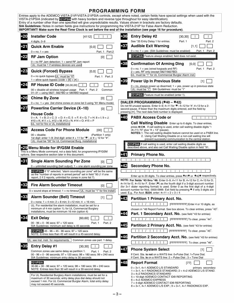
PROGRAMMING FORM Entries apply to the ADEMCO VISTA-21iP/VISTA-21iPSIA controls, except where noted, certain fields have special settings when used with the VISTA-21iPSIA (indicated by V21iPSIA with heavy borders and reverse type throughout for easy identification). Entry of a number other than one specified will give unpredictable results. Values shown in brackets are factory defaults. SIA Guidelines: Notes in certain fields give instructions for programming the VISTA-21iP for False Alarm Reduction. IMPORTANT! Make sure the Real-Time Clock is set before the end of the installation (see page 16 for procedure).
∗∗∗∗20 Installer Code [4112] | | | 4 digits, 0–9
∗∗∗∗21 Quick Arm Enable [0,0]
0 = no; 1 = yes Part. 1 Part.2
∗∗∗∗22 RF Jam Option [0]
0 = no RF Jam detection; 1 = send RF Jam report UL: must be 1 if wireless devices are used
∗∗∗∗23 Quick (Forced) Bypass [0,0]
0 = no quick bypass UL: must be “0” Part. 1 Part. 2 1 = allow quick bypass (code + [6] + [#] )
∗∗∗∗24 RF House ID Code [00,00,00] | | |
00 = disable all wireless keypad usage Part. 1 Part. 2 Common 01–31 = using 5827, 5827BD or 5804BD keypad
∗∗∗∗26 Chime By Zone [0]
0 = no; 1 = yes (list chime zones on zone list 3 using *81 Menu mode)
∗∗∗∗27 Powerline Carrier Device (X–10) [0]
House Code 0 = A; 1 = B; 2 = C; 3 = D; 4 = E; 5 = F; 6 = G; 7 = H; 8 = I; 9 = J;
#10 = K; #11 = L; #12 = M; #13 = N; #14 = O; #15 = P UL: not for fire or UL installations
∗∗∗∗28 Access Code For Phone Module [00] | 00 = disable; (Partition 1 only) 1st digit: enter 1–9; 2nd digit: enter # + 11 for "✱", or # + 12 for "#". UL: must be “00” for UL Commercial Burg. installations
∗∗∗∗29 Menu Mode for IP/GSM Enable This is a Menu Mode command, not a data field, for programming IP/GSM options. See respective section later in this document.
∗∗∗∗31 Single Alarm Sounding Per Zone [0] 0 = unlimited sounding (bell output); 1 = one alarm sounding per zone
V21iPSIA: If “0” selected, “alarm sounding per zone” will be the same as the “number of reports in armed period” set in field *93 (1 if one report, 2 if 2 reports, unlimited for zones in zone list 7).
∗∗∗∗32 Fire Alarm Sounder Timeout [0]
0 = sound stops at timeout; 1 = no timeout UL: must be “1” for fire install.
∗∗∗∗33 Alarm Sounder (Bell) Timeout [1] 0 = none; 1 = 4 min; 2 = 8 min; 3 =12 min; 4 = 16 min;
UL: For residential fire alarm installation, must be set for a minimum of 4 min (option 1); for UL Commercial Burglary installations, must be minimum 16 min (option 4)
∗∗∗∗34 Exit Delay [60,60] | |
00 - 96 = 0 - 96 secs; 97 = 120 secs Part. 1 Part. 2 SIA Guidelines: minimum exit delay is 45 seconds
V21iPSIA: 45 - 96 = 45 - 96 secs; 97 = 120 secs NOTE: Entries less than 45 will result in a 45-second delay.
UL: see inst. instr. for requirements. Common zones use part. 1 delay.
∗∗∗∗35 Entry Delay #1 [30,30] | |
Common zones use same delay as partition 1. Part. 1 Part. 2 00 - 96 = 0 - 96 seconds; 97 = 120 secs; 98 = 180 secs; 99 = 240 secs SIA Guidelines: minimum entry delay is 30 seconds
V21iPSIA: 30-96 = 30 - 96 secs; 97 = 120 secs; 98 = 180 secs; 99 = 240 secs NOTE: Entries less than 30 will result in a 30-second delay.
For UL Residential Burglary Alarm installations, must be set for a maximum of 30 seconds; entry delay plus dial delay should not exceed 1 min. For UL Commercial Burglar Alarm, total entry delay may not exceed 45 seconds.
∗∗∗∗36 Entry Delay #2 [30,30] | |
See *35 Entry Delay 1 for entries. Part. 1 Part. 2 ∗∗∗∗37 Audible Exit Warning [1,1] 0 = no; 1 = yes (SIA Guidelines: must be enabled) Part. 1 Part. 2
V21iPSIA: Feature always enabled; field does not exist.
∗∗∗∗38 Confirmation Of Arming Ding [0,0]
0 = no; 1 = yes (wired keypads and RF) Part. 1 Part. 2 2 = yes, RF only (except 5827/5827BD) UL: must be “1” for UL Commercial Burglar Alarm inst.
∗∗∗∗39 Power Up In Previous State [1] 0 = no, always power up disarmed; 1 = yes, power up in previous state UL: must be “1” SIA Guidelines: must be “1”
V21iPSIA: Feature must be enabled (enter 1).
DIALER PROGRAMMING (✱40 – ✱42) Do not fill unused spaces. Enter 0–9; #+11 for '✱'; #+12 for '#'; #+13 for a 2-second pause. If fewer than the maximum digits entered, exit the field by pressing [✶]. The next data field number is displayed.
∗∗∗∗40 PABX Access Code or | | | | |
Call Waiting Disable Enter up to 6 digits. To clear entries, press ✱40✱. If call waiting is used, enter call waiting disable digits “∗ (#+11) 70” plus “# + 13” (pause). NOTES: 1. The call waiting disable feature cannot be used on a PABX line.
2. Using Call Waiting Disable on a non-call waiting line will prevent successful communication to the central station.
V21iPSIA: If call waiting is used, enter call waiting disable digits as described above, and also set Call Waiting Disable option in field *91.
∗∗∗∗41 Primary Phone No. | | | | | | | | | | | | | | | | | | |
∗∗∗∗42 Secondary Phone No. | | | | | | | | | | | | | | | | | | |
Enter up to 20 digits. To clear entries, press ✱41✱ or ✱42✱ respectively.
NOTE: For fields *43 thru *46: Enter 0–9; #+11 for B; #+12 for C; #+13 for D; #+14 for E; #+15 for F. Enter [✱] as the fourth digit if a 3-digit account number (for 3+1 dialer reporting format) is used. Enter 0 as the first digit of a 4-digit account number for Nos. 0000-0999. Exit field by pressing ✱ if only 3 digits are used. E.g., For Acct. B234, enter: #+11 + 2 + 3 + 4
∗∗∗∗43 Partition 1 Primary Acct. No. | | | / | | | | | [FFFFFFFFFF] Enter 4 or 10 digits, as
chosen in *48 Report Format. See box above. To clear entries, press *43*.
∗∗∗∗44 Part. 1 Secondary Acct. No. (see field *43 for entries)
| | | / | | | | | [FFFFFFFFFF] To clear, press *44*.
∗∗∗∗45 Partition 2 Primary Acct. No. (see field *43 for entries)
| | | / | | | | | [FFFFFFFFFF] To clear, press *45*.
∗∗∗∗46 Partition 2 Secondary Acct. No. (see field *43 for entries)
| | | / | | | | | [FFFFFFFFFF] To clear, press *46*.
∗∗∗∗47 Phone System Select [1]
If Cent. Sta. is not on a WATS line: 0=Pulse Dial; 1=Tone Dial; if Cent. Sta. is on a WATS line: 2 = Pulse Dial ; 3 = Tone Dial
∗∗∗∗48 Report Format [77] 0 = 3+1, 4+1 ADEMCO L/S STANDARD primary secondary 1 = 3+1, 4+1 RADIONICS STANDARD; 2 = 4+2 ADEMCO L/S STAND. 3 = 4+2 RADIONICS STANDARD 5 = 10-digit ADEMCO CONTACT ID® REPORTING 6 = 4+2 ADEMCO EXPRESS 7 = 4-digit ADEMCO CONTACT ID® REPORTING 8 = 3+1, 4+1 ADEMCO L/S EXP.; 9 = 3+1, 4+1 RADIONICS EXP.
– 3 –
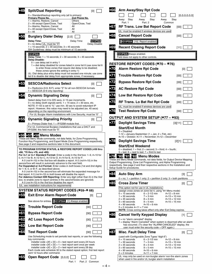
∗∗∗∗49 Split/Dual Reporting [0]
0 = Standard/backup reporting only (all to primary) Primary Phone No. 2nd Phone No. 1 = Alarms, Restore, Cancel Others 2 = All except Open/Close, Test Open/Close, Test 3 = Alarms, Restore, Cancel All 4 = All except Open/Close, Test All 5 = All All
∗∗∗∗50 Burglary Dialer Delay [2,0]
Delay Time: Delay Time V21iPSIA 0 = no delay UL: must be “0” Delay Disable 1 = 15 seconds; 2 = 30 seconds; 3 = 45 seconds
SIA Guidelines: delay must be minimum of 15 seconds
V21iPSIA: Delay Time: 1 = 15 seconds; 2 = 30 seconds; 3 = 45 seconds Delay Disable: 0 = use delay set in entry 1 1 = dial delay disabled for zones listed in zone list 6 (use zone list 6
to enter those zones that require dial delay to be disabled; these zones ignore the setting in entry 1)
UL: Dial delay plus entry delay must not exceed one minute; use zone list 6 to disable dial delay from appropriate zones, if necessary.
∗∗∗∗53 SESCOA/Radionics Select [0] 0 = Radionics (0-9, B-F); enter “0” for all non-SESCOA formats 1 = SESCOA (0-9 only reporting)
∗∗∗∗54 Dynamic Signaling Delay [0]
Select delay from 0 to 225 secs, in 15-sec increments. 0 = no delay (both signals sent); 1 = 15 secs; 2 = 30 secs, etc. NOTE: If ∗55 is set to “0,” use min. 30 sec to avoid redundant IP
report. However, this value may need to be adjusted (ex. 45 secs) depending on the reporting environment.
For UL Burglar Alarm installations with Line Security, must be “0”
∗∗∗∗55 Dynamic Signaling Priority [0]
0 = Primary Dialer first; 1 = IP/GSM module first. For UL Commercial Burglary installations that use a DACT and IP/GSM, this field must be “0”.
∗∗∗∗56, ∗∗∗∗57, ∗∗∗∗58 Menu Modes These are Menu Mode commands, not data fields, for Zone Programming, Function Key Programming, and Expert Mode Zone Programming respectively. See page 2 and respective sections later in this document.
TO PROGRAM SYSTEM STATUS, & RESTORE REPORT CODES (∗∗∗∗59 thru ∗∗∗∗68, *70 thru ∗∗∗∗76, and ∗∗∗∗89): For 3+1 or 4+1 Standard Format: Enter a code in the first box: 1–9, #+10 for 0, #+11 for B, #+12 for C, #+13 for D, #+14 for E, #+15 for F. A 0 (not #+10) in the first box will disable a report. A 0 (not #+10) in the second box will result in automatic advance to the next field. For Expanded or 4+2 Format: Enter codes in both boxes (1st and 2nd digits) for 1–9, 0, or B–F, as described above. A 0 (not #+10) in the second box will eliminate the expanded message for that report. A 0 (not #+10) in both boxes will disable the report. For Ademco Contact ID® Reporting: Enter any digit (other than 0) in the first box, to enable zone to report (entries in the second boxes are ignored). A 0 (not #+10) in the first box disables the report. UL: see installation instructions for requirements
SYSTEM STATUS REPORT CODES (✱59–✱ 68)
∗∗∗∗59 Exit Error Alarm Report Code [0]
See above for entries. V21iPSIA: [1] Always enabled.
∗∗∗∗60 Trouble Report Code [00] |
∗∗∗∗61 Bypass Report Code [00] |
∗∗∗∗62 AC Loss Report Code [00] |
∗∗∗∗63 Low Bat Report Code [00] |
∗∗∗∗64 Test Report Code [00] |
Use Scheduling mode to set periodic test reports, or use the following key commands:
installer code +[#] + [0] + 0 = test report sent every 24 hours installer code +[#] + [0] + 1 = test report sent once per week installer code +[#] + [0] + 2 = test report sent every 28 day Each mode sets schedule 32 to the stated repeat option; first test report
sent 12 hours after command.
∗∗∗∗65 Open Report Code [0,0,0]
Part. 1 Part. 2 Common
∗∗∗∗66 Arm Away/Stay Rpt Code [0,0,0,0,0,0]
Away Stay Away Stay Away Stay Part. 1 Part. 2 Common
∗∗∗∗67 RF Trans. Low Bat Report Code [00] |
UL: must be enabled if wireless devices are used
∗∗∗∗68 Cancel Report Code [00] |
V21iPSIA: [10] Report enabled.
∗∗∗∗69 Recent Closing Report Code [11] |
V21iPSIA:Always enabled. Field does not apply to other controls.
RESTORE REPORT CODES (✱70 – ✱76) ∗∗∗∗70 Alarm Restore Rpt Code [0]
∗∗∗∗71 Trouble Restore Rpt Code [00] |
∗∗∗∗72 Bypass Restore Rpt Code [00] |
∗∗∗∗73 AC Restore Rpt Code [00] |
∗∗∗∗74 Low Bat Restore Rpt Code [00] |
∗∗∗∗75 RF Trans. Lo Bat Rst Rpt Code [00] |
UL: must be enabled if wireless devices are used
∗∗∗∗76 Test Restore Rpt Code [00] |
OUTPUT AND SYSTEM SETUP (✱77 – ✱93)
∗∗∗∗77 Daylight Savings Time [3][11] |
Start/End Month 0 = Disabled 1-12 = January-September (1 = Jan, 2 = Feb, etc) #+10 = October; #+11 = November; #+12 = December
∗∗∗∗78 Daylight Savings Time [2][1] |
Start/End Weekend 0 = disabled; 1 = first; 2 = second; 3 = third; 4 = fourth; 5 = last; 6 = next to last; 7 = third to last
∗∗∗∗79, *80, *81, *82 Menu Modes These are Menu Mode commands, not data fields, for Output Device Mapping, Output Programming, Zone List Programming, and Alpha Programming respectively. See page 2 and their respective sections in the Installation and Setup Guide for procedures.
∗∗∗∗84 Auto Stay Arm [3] 0 = no; 1 = partition 1 only; 2 = partition 2 only; 3 = both partitions
∗∗∗∗85 Cross Zone Timer [0] This option not for use in UL installations. (assign cross zones on zone list 4, using *81 Menu mode) 0 = 15 seconds 6 = 2-1/2 min #+12 = 8 min 1 = 30 seconds 7 = 3 min #+13 = 10 min 2 = 45 seconds 8 = 4 min #+14 = 12 min 3 = 60 seconds 9 = 5 min #+15 = 15 min 4 = 90 seconds #+10 = 6 min 5 = 2 minutes #+11 = 7 min NOTE: Cross zoning takes effect only after Exit Delay expires.
∗∗∗∗86 Cancel Verify Keypad Display [1] 0 = no “alarm canceled” display 1 = display “Alarm Canceled” when system is disarmed after an alarm
has occurred. (To clear the “ALARM CANCELED” display, the user must enter the security code + OFF again.)
∗∗∗∗87 Misc. Fault Delay Time [0] (used with Configurable Zone Types “digit 6”) 0 = 15 seconds 6 = 2-1/2 min #+12 = 8 min 1 = 30 seconds 7 = 3 min #+13 = 10 min 2 = 45 seconds 8 = 4 min #+14 = 12 min 3 = 60 seconds 9 = 5 min #+15 = 15 min 4 = 90 seconds #+10 = 6 min 5 = 2 minutes #+11 = 7 min
UL: may only be used on non-burglar alarm/ non-fire alarm zones when used in fire and/or UL burglar alarm installation
– 4 –
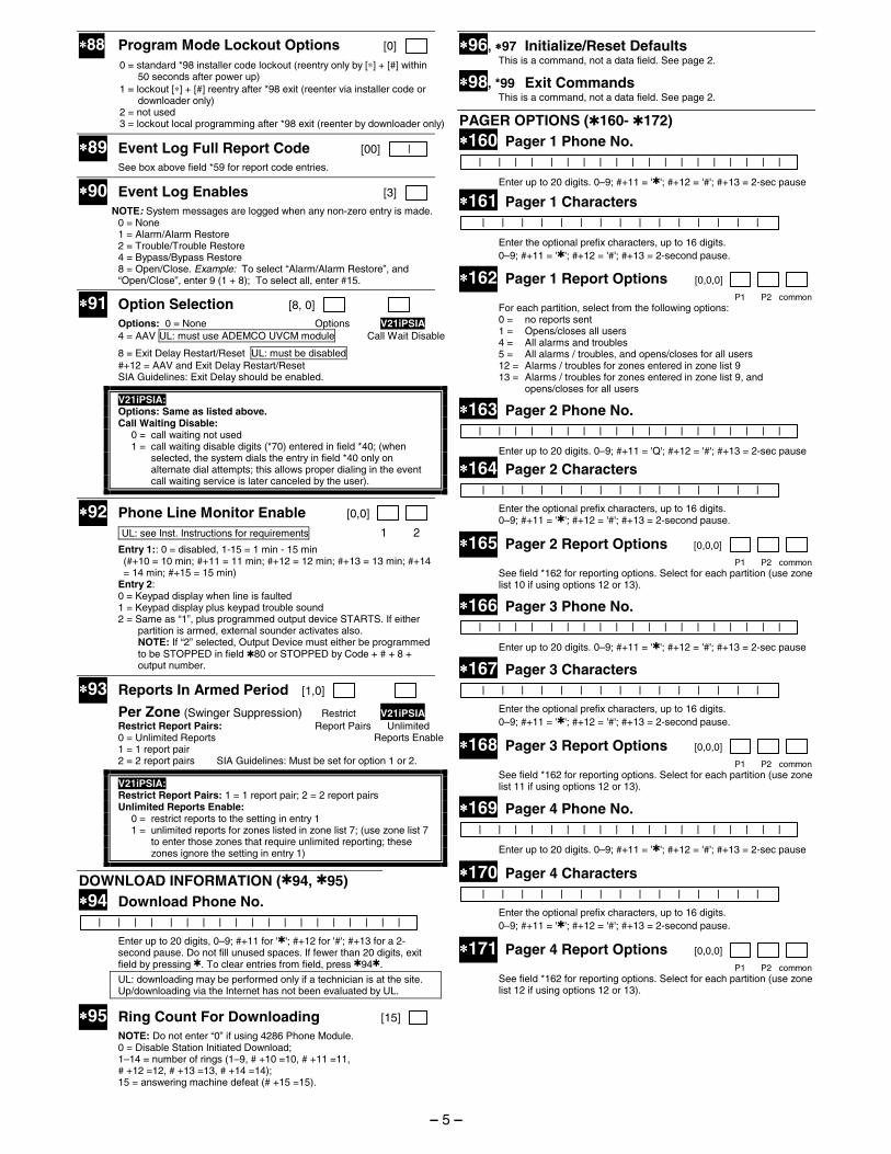
∗∗∗∗88 Program Mode Lockout Options [0] 0 = standard *98 installer code lockout (reentry only by [∗] + [#] within
50 seconds after power up) 1 = lockout [∗] + [#] reentry after *98 exit (reenter via installer code or
downloader only) 2 = not used 3 = lockout local programming after *98 exit (reenter by downloader only)
∗∗∗∗89 Event Log Full Report Code [00] | See box above field *59 for report code entries.
∗∗∗∗90 Event Log Enables [3] NOTE: System messages are logged when any non-zero entry is made. 0 = None 1 = Alarm/Alarm Restore 2 = Trouble/Trouble Restore 4 = Bypass/Bypass Restore 8 = Open/Close. Example: To select “Alarm/Alarm Restore”, and
“Open/Close”, enter 9 (1 + 8); To select all, enter #15.
∗∗∗∗91 Option Selection [8, 0]
Options: 0 = None Options V21iPSIA 4 = AAV UL: must use ADEMCO UVCM module Call Wait Disable
8 = Exit Delay Restart/Reset UL: must be disabled #+12 = AAV and Exit Delay Restart/Reset SIA Guidelines: Exit Delay should be enabled.
V21iPSIA: Options: Same as listed above. Call Waiting Disable: 0 = call waiting not used 1 = call waiting disable digits (*70) entered in field *40; (when
selected, the system dials the entry in field *40 only on alternate dial attempts; this allows proper dialing in the event call waiting service is later canceled by the user).
∗∗∗∗92 Phone Line Monitor Enable [0,0]
UL: see Inst. Instructions for requirements 1 2
Entry 1:: 0 = disabled, 1-15 = 1 min - 15 min (#+10 = 10 min; #+11 = 11 min; #+12 = 12 min; #+13 = 13 min; #+14
= 14 min; #+15 = 15 min) Entry 2: 0 = Keypad display when line is faulted 1 = Keypad display plus keypad trouble sound 2 = Same as “1”, plus programmed output device STARTS. If either
partition is armed, external sounder activates also. NOTE: If “2” selected, Output Device must either be programmed
to be STOPPED in field ✱80 or STOPPED by Code + # + 8 + output number.
∗∗∗∗93 Reports In Armed Period [1,0]
Per Zone (Swinger Suppression) Restrict V21iPSIA Restrict Report Pairs: Report Pairs Unlimited 0 = Unlimited Reports Reports Enable 1 = 1 report pair 2 = 2 report pairs SIA Guidelines: Must be set for option 1 or 2.
V21iPSIA: Restrict Report Pairs: 1 = 1 report pair; 2 = 2 report pairs Unlimited Reports Enable: 0 = restrict reports to the setting in entry 1 1 = unlimited reports for zones listed in zone list 7; (use zone list 7
to enter those zones that require unlimited reporting; these zones ignore the setting in entry 1)
DOWNLOAD INFORMATION (✱94, ✱95) ∗∗∗∗94 Download Phone No. | | | | | | | | | | | | | | | | | | |
Enter up to 20 digits, 0–9; #+11 for '✱'; #+12 for '#'; #+13 for a 2-second pause. Do not fill unused spaces. If fewer than 20 digits, exit field by pressing ✱. To clear entries from field, press ✱94✱.
UL: downloading may be performed only if a technician is at the site. Up/downloading via the Internet has not been evaluated by UL.
∗∗∗∗95 Ring Count For Downloading [15]
NOTE: Do not enter “0” if using 4286 Phone Module. 0 = Disable Station Initiated Download; 1–14 = number of rings (1–9, # +10 =10, # +11 =11, # +12 =12, # +13 =13, # +14 =14); 15 = answering machine defeat (# +15 =15).
∗∗∗∗96, ∗∗∗∗97 Initialize/Reset Defaults This is a command, not a data field. See page 2.
∗∗∗∗98, *99 Exit Commands This is a command, not a data field. See page 2.
PAGER OPTIONS (✱160- ✱172) ∗∗∗∗160 Pager 1 Phone No. | | | | | | | | | | | | | | | | | | |
Enter up to 20 digits. 0–9; #+11 = '✱'; #+12 = '#'; #+13 = 2-sec pause
∗∗∗∗161 Pager 1 Characters
| | | | | | | | | | | | | | |
Enter the optional prefix characters, up to 16 digits. 0–9; #+11 = '✱'; #+12 = '#'; #+13 = 2-second pause.
∗∗∗∗162 Pager 1 Report Options [0,0,0] P1 P2 common For each partition, select from the following options: 0 = no reports sent 1 = Opens/closes all users 4 = All alarms and troubles 5 = All alarms / troubles, and opens/closes for all users 12 = Alarms / troubles for zones entered in zone list 9 13 = Alarms / troubles for zones entered in zone list 9, and
opens/closes for all users
∗∗∗∗163 Pager 2 Phone No. | | | | | | | | | | | | | | | | | | |
Enter up to 20 digits. 0–9; #+11 = 'Q'; #+12 = '#'; #+13 = 2-sec pause
∗∗∗∗164 Pager 2 Characters
| | | | | | | | | | | | | | |
Enter the optional prefix characters, up to 16 digits. 0–9; #+11 = '✱'; #+12 = '#'; #+13 = 2-second pause.
∗∗∗∗165 Pager 2 Report Options [0,0,0] P1 P2 common See field *162 for reporting options. Select for each partition (use zone
list 10 if using options 12 or 13).
∗∗∗∗166 Pager 3 Phone No. | | | | | | | | | | | | | | | | | | |
Enter up to 20 digits. 0–9; #+11 = '✱'; #+12 = '#'; #+13 = 2-sec pause
∗∗∗∗167 Pager 3 Characters
| | | | | | | | | | | | | | |
Enter the optional prefix characters, up to 16 digits. 0–9; #+11 = '✱'; #+12 = '#'; #+13 = 2-second pause.
∗∗∗∗168 Pager 3 Report Options [0,0,0] P1 P2 common See field *162 for reporting options. Select for each partition (use zone
list 11 if using options 12 or 13).
∗∗∗∗169 Pager 4 Phone No. | | | | | | | | | | | | | | | | | | |
Enter up to 20 digits. 0–9; #+11 = '✱'; #+12 = '#'; #+13 = 2-sec pause
∗∗∗∗170 Pager 4 Characters
| | | | | | | | | | | | | | |
Enter the optional prefix characters, up to 16 digits. 0–9; #+11 = '✱'; #+12 = '#'; #+13 = 2-second pause.
∗∗∗∗171 Pager 4 Report Options [0,0,0] P1 P2 common See field *162 for reporting options. Select for each partition (use zone
list 12 if using options 12 or 13).
– 5 –
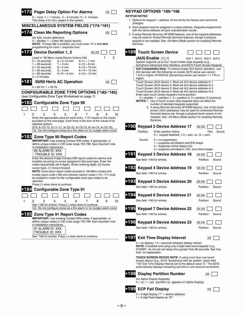
∗∗∗∗172 Pager Delay Option For Alarms [3]
0 = none; 1 = 1 minute; 2 = 2 minutes; 3 = 3 minutes This delay is for ALL pagers in the system.
MISCELLANEOUS SYSTEM FIELDS (*174-*181)
∗∗∗∗174 Clean Me Reporting Options [0] (for ESL smoke detectors) 0 = disable; 1 = Clean Me signal reports; NOTE: If Clean Me is enabled, you must enter “3” in field ✱56
programming for zone 1 response time.
∗∗∗∗177 Device Duration 1, 2 [0] [0]
(used in *80 Menu mode-Device Actions 5/6) 1 2 0 = 15 seconds 6 = 2-1/2 min #+11 = 7 min 1 = 30 seconds 7 = 3 min #+12 = 8 min 2 = 45 seconds 8 = 4 min #+13 = 10 min 3 = 60 seconds 9 = 5 min #+14 = 12 min 4 = 90 seconds #+10 = 6 min #+15 = 15 min 5 = 2 minutes
∗∗∗∗181 50/60 Hertz AC Operation [0]
0 = 60 Hz; 1 = 50 Hz
CONFIGURABLE ZONE TYPE OPTIONS (*182-*185) (see Configurable Zone Type Worksheet on page 7)
∗∗∗∗182 Configurable Zone Type 90
1 2 3 4 5 6 7 8 9 10 Enter the appropriate value for each entry, 1-10, based on the charts provided on the next page. Each entry is the sum of the values of its selected options
(0-9, #+10=10, #+11=11, #+12=12, #+13=13, #+14=14, #+15=15). UL: Do not configure zones as a fire alarm or UL burglar alarm zone.
∗∗∗∗183 Zone Type 90 Report Codes IMPORTANT: Use existing Contact ID® codes, if appropriate, or define unique codes in CID code range 750-789. See important note in installation instructions.
90 ALARM ID: XXX TROUBLE ID: XXX
Enter the desired 3-digit Contact ID® report codes for alarms and troubles occurring on zones assigned to this zone type. Enter the codes sequentially (all 6 digits). When entering digits, [#] moves cursor back, [∗] moves forward. NOTE: Zone alarm report codes (prompt in ∗56 Menu mode) and trouble report code (∗60) and relevant restore codes (∗70, ∗71) must be enabled in order for the configurable zone type codes to be reported. Press [∗] when done to continue.
∗∗∗∗184 Configurable Zone Type 91
1 2 3 4 5 6 7 8 9 10 See ∗182 for entries. Press [∗] when done to continue.
UL: Do not configure zones as a fire alarm or UL burglar alarm zone.
∗∗∗∗185 Zone Type 91 Report Codes IMPORTANT: Use existing Contact ID® codes, if appropriate, or define unique codes in CID code range 750-789. See important note in installation instructions.
91 ALARM ID: XXX TROUBLE ID: XXX
See *183 for entries. Press [∗] when done to continue.
KEYPAD OPTIONS *189-*196 KEYPAD NOTES:
1. Options for keypad 1, address 16 are set by the factory and cannot be changed.
2. Each keypad must be assigned a unique address. Keypads programmed with the same address will give unpredictable results.
3. If using Remote Services (IP/GSM feature), one of the keypad addresses may be used for limited Remote Services features, though a physical keypad is not installed. See ∗29 Menu Mode section for enabling Remote Services.
∗∗∗∗189 Touch Screen Device
(AUI) Enable [1] [1] AUI 1 AUI 2 AUI 3 AUI 4 System supports up to four touch screen style keypads (e.g.,
Symphony Advanced User Interface, and 6270 Touch Screen Keypad). AUI Compatibility Note: To ensure proper AUI device operation, use AUI devices with the following rev levels: 6270 series use version 1.0.9 or higher; 8132/8142 (Symphony) series use version 1.1.175 or higher.
Touch Screen (AUI) device 1: Must set AUI device address to 1 Touch Screen (AUI) device 2: Must set AUI device address to 2 Touch Screen (AUI) device 3: Must set AUI device address to 5 Touch Screen (AUI) device 4: Must set AUI device address to 6 Enter each touch screen keypad’s home partition 0 = disable; 1 = partition 1; 2 = partition 2; 3 = partition 3 (common)
NOTES: 1. Use of touch screen style keypads does not affect the number of standard keypads supported.
2. If using Remote Services (IP/GSM feature), one of the touch screen (AUI) addresses may be used for enhanced Remote Services feature set, though a physical touch screen is not installed. See ∗29 Menu Mode section for enabling Remote Services.
∗∗∗∗190 Keypad 2 Device Address 17 [0] [0]
Partition: Enter partition where: Part. Sound 0 = keypad disabled; 1-3 = part. no. (3 = com)
Sound: 0 = no suppression 1 = suppress arm/disarm and E/E beeps 2 = Suppress chime beeps only 3 = suppress arm/disarm, E/E, and chime beeps
∗∗∗∗191 Keypad 3 Device Address 18 [0] [0]
See field ∗190 for entries. Partition Sound
∗∗∗∗192 Keypad 4 Device Address 19 [0] [0]
See field ∗190 for entries. Partition Sound
∗∗∗∗193 Keypad 5 Device Address 20 [0] [0]
See field ∗190 for entries. Partition Sound
∗∗∗∗194 Keypad 6 Device Address 21 [0] [0] See field ∗190 for entries. Partition Sound
∗∗∗∗195 Keypad 7 Device Address 22 [0] [0]
See field ∗190 for entries. Partition Sound
∗∗∗∗196 Keypad 8 Device Address 23 [0] [0]
See field ∗190 for entries. Partition Sound
∗∗∗∗197 Exit Time Display Interval [0] 0 = no display; 1-5 = seconds between display refresh NOTE: If enabled and using only 2-digit fixed-word keypads (e.g.,
6150RF), do not set exit delay time greater than 96 seconds. See Inst. Instr. for explanation.
TOUCH SCREEN DEVICE NOTE: If using more than one touch screen device (e.g., 6270, Symphony) with the system, leave field *197 Exit Time Display Interval set to the default value “0.” The 6270 automatically displays remaining exit time in one-second increments.
∗∗∗∗198 Display Partition Number [0] (for Alpha Display Keypads) 0 = no; 1 = yes (partition no. appears on Alpha Display)
∗∗∗∗199 ECP Fail Display [0] 0 = 3-digit display (“1” + device address) 1 = 2-digit fixed-display as “91”
– 6 –
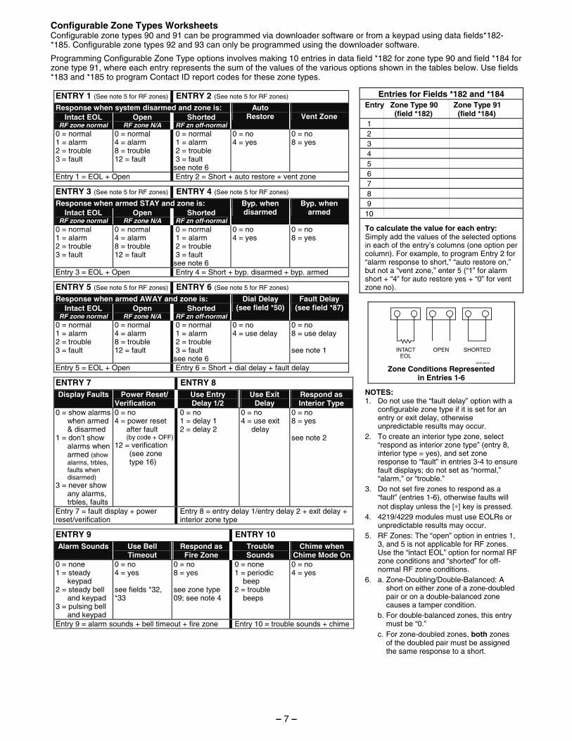
Configurable Zone Types Worksheets Configurable zone types 90 and 91 can be programmed via downloader software or from a keypad using data fields*182-*185. Configurable zone types 92 and 93 can only be programmed using the downloader software.
Programming Configurable Zone Type options involves making 10 entries in data field *182 for zone type 90 and field *184 for zone type 91, where each entry represents the sum of the values of the various options shown in the tables below. Use fields *183 and *185 to program Contact ID report codes for these zone types.
ENTRY 1 (See note 5 for RF zones) ENTRY 2 (See note 5 for RF zones) Response when system disarmed and zone is:
Intact EOL RF zone normal
Open RF zone N/A
Shorted RF zn off-normal
Auto Restore
Vent Zone
0 = normal 1 = alarm 2 = trouble 3 = fault
0 = normal 4 = alarm 8 = trouble 12 = fault
0 = normal 1 = alarm 2 = trouble 3 = fault see note 6
0 = no 4 = yes
0 = no 8 = yes
Entry 1 = EOL + Open Entry 2 = Short + auto restore + vent zone
ENTRY 3 (See note 5 for RF zones) ENTRY 4 (See note 5 for RF zones) Response when armed STAY and zone is:
Intact EOL RF zone normal
Open RF zone N/A
Shorted RF zn off-normal
Byp. when disarmed
Byp. when armed
0 = normal 1 = alarm 2 = trouble 3 = fault
0 = normal 4 = alarm 8 = trouble 12 = fault
0 = normal 1 = alarm 2 = trouble 3 = fault see note 6
0 = no 4 = yes
0 = no 8 = yes
Entry 3 = EOL + Open Entry 4 = Short + byp. disarmed + byp. armed
ENTRY 5 (See note 5 for RF zones) ENTRY 6 (See note 5 for RF zones) Response when armed AWAY and zone is:
Intact EOL RF zone normal
Open RF zone N/A
Shorted RF zn off-normal
Dial Delay (see field *50)
Fault Delay (see field *87)
0 = normal 1 = alarm 2 = trouble 3 = fault
0 = normal 4 = alarm 8 = trouble 12 = fault
0 = normal 1 = alarm 2 = trouble 3 = fault see note 6
0 = no 4 = use delay
0 = no 8 = use delay see note 1
Entry 5 = EOL + Open Entry 6 = Short + dial delay + fault delay
ENTRY 7 ENTRY 8 Display Faults Power Reset/
Verification Use Entry Delay 1/2
Use Exit Delay
Respond as Interior Type
0 = show alarms when armed & disarmed
1 = don’t show alarms when armed (show alarms, trbles, faults when disarmed)
3 = never show any alarms, trbles, faults
0 = no 4 = power reset
after fault (by code + OFF)
12 = verification (see zone
type 16)
0 = no 1 = delay 1 2 = delay 2
0 = no 4 = use exit
delay
0 = no 8 = yes see note 2
Entry 7 = fault display + power reset/verification
Entry 8 = entry delay 1/entry delay 2 + exit delay + interior zone type
ENTRY 9 ENTRY 10 Alarm Sounds Use Bell
Timeout Respond as
Fire Zone Trouble Sounds
Chime when Chime Mode On
0 = none 1 = steady
keypad 2 = steady bell
and keypad 3 = pulsing bell
and keypad
0 = no 4 = yes see fields *32, *33
0 = no 8 = yes see zone type 09; see note 4
0 = none 1 = periodic
beep 2 = trouble
beeps
0 = no 4 = yes
Entry 9 = alarm sounds + bell timeout + fire zone Entry 10 = trouble sounds + chime
Entries for Fields *182 and *184 Entry Zone Type 90 Zone Type 91 (field *182) (field *184) 1 2 3 4 5 6 7 8 9 10
To calculate the value for each entry: Simply add the values of the selected options in each of the entry’s columns (one option per column). For example, to program Entry 2 for “alarm response to short,” “auto restore on,” but not a “vent zone,” enter 5 (“1” for alarm short + “4” for auto restore yes + “0” for vent zone no).
OPEN SHORTEDINTACTEOL
ZONE-003-V0 Zone Conditions Represented
in Entries 1-6
NOTES: 1. Do not use the “fault delay” option with a
configurable zone type if it is set for an entry or exit delay, otherwise unpredictable results may occur.
2. To create an interior type zone, select “respond as interior zone type” (entry 8, interior type = yes), and set zone response to “fault” in entries 3-4 to ensure fault displays; do not set as “normal,” “alarm,” or “trouble.”
3. Do not set fire zones to respond as a “fault” (entries 1-6), otherwise faults will not display unless the [∗] key is pressed.
4. 4219/4229 modules must use EOLRs or unpredictable results may occur.
5. RF Zones: The “open” option in entries 1, 3, and 5 is not applicable for RF zones. Use the “intact EOL” option for normal RF zone conditions and “shorted” for off-normal RF zone conditions.
6. a. Zone-Doubling/Double-Balanced: A short on either zone of a zone-doubled pair or on a double-balanced zone causes a tamper condition.
b. For double-balanced zones, this entry must be “0.”
c. For zone-doubled zones, both zones of the doubled pair must be assigned the same response to a short.
– 7 –
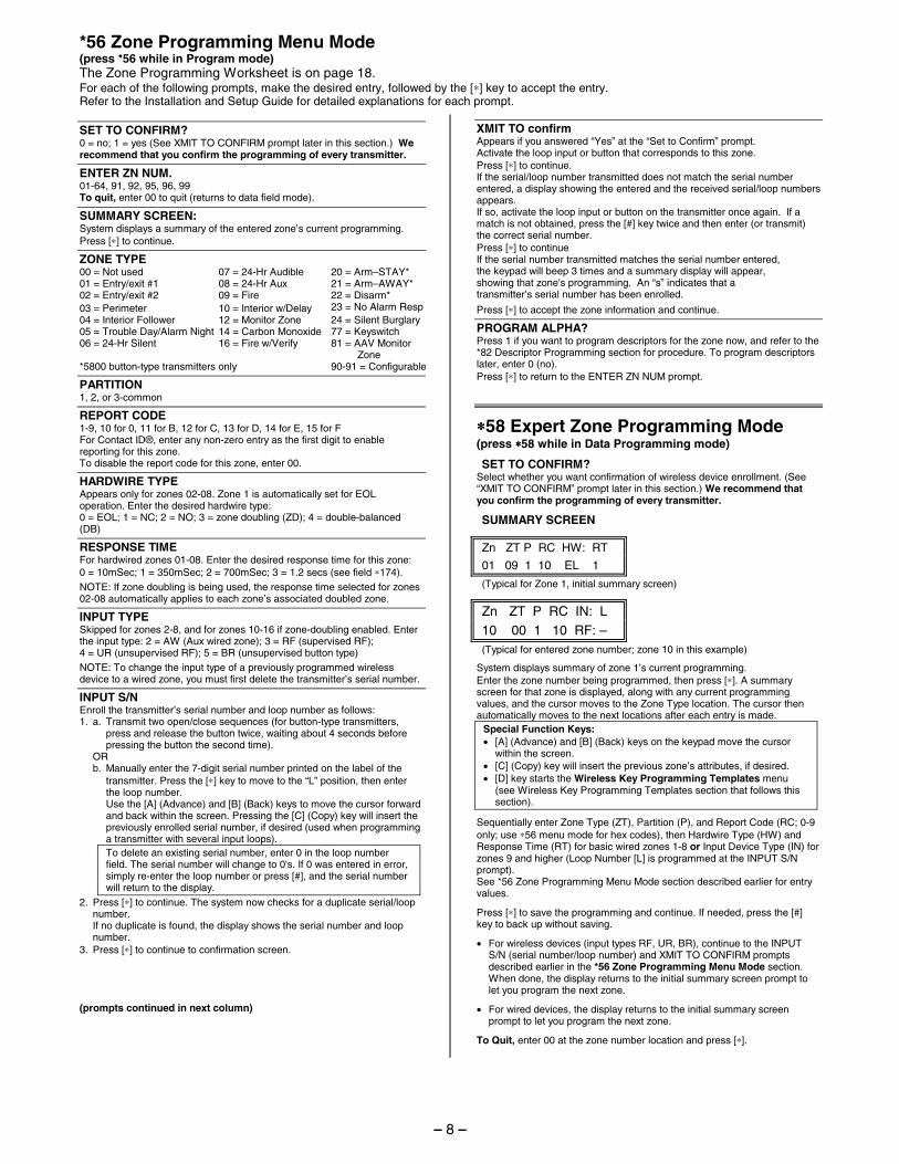
*56 Zone Programming Menu Mode (press *56 while in Program mode) The Zone Programming Worksheet is on page 18. For each of the following prompts, make the desired entry, followed by the [∗] key to accept the entry. Refer to the Installation and Setup Guide for detailed explanations for each prompt.
SET TO CONFIRM? 0 = no; 1 = yes (See XMIT TO CONFIRM prompt later in this section.) We recommend that you confirm the programming of every transmitter.
ENTER ZN NUM. 01-64, 91, 92, 95, 96, 99 To quit, enter 00 to quit (returns to data field mode).
SUMMARY SCREEN: System displays a summary of the entered zone’s current programming. Press [∗] to continue.
ZONE TYPE 00 = Not used 07 = 24-Hr Audible 20 = Arm–STAY* 01 = Entry/exit #1 08 = 24-Hr Aux 21 = Arm–AWAY* 02 = Entry/exit #2 09 = Fire 22 = Disarm* 03 = Perimeter 10 = Interior w/Delay 23 = No Alarm Resp 04 = Interior Follower 12 = Monitor Zone 24 = Silent Burglary 05 = Trouble Day/Alarm Night 14 = Carbon Monoxide 77 = Keyswitch 06 = 24-Hr Silent 16 = Fire w/Verify 81 = AAV Monitor Zone *5800 button-type transmitters only 90-91 = Configurable
PARTITION 1, 2, or 3-common
REPORT CODE 1-9, 10 for 0, 11 for B, 12 for C, 13 for D, 14 for E, 15 for F For Contact ID®, enter any non-zero entry as the first digit to enable reporting for this zone. To disable the report code for this zone, enter 00.
HARDWIRE TYPE Appears only for zones 02-08. Zone 1 is automatically set for EOL operation. Enter the desired hardwire type: 0 = EOL; 1 = NC; 2 = NO; 3 = zone doubling (ZD); 4 = double-balanced (DB)
RESPONSE TIME For hardwired zones 01-08. Enter the desired response time for this zone: 0 = 10mSec; 1 = 350mSec; 2 = 700mSec; 3 = 1.2 secs (see field ∗174). NOTE: If zone doubling is being used, the response time selected for zones 02-08 automatically applies to each zone’s associated doubled zone.
INPUT TYPE Skipped for zones 2-8, and for zones 10-16 if zone-doubling enabled. Enter the input type: 2 = AW (Aux wired zone); 3 = RF (supervised RF); 4 = UR (unsupervised RF); 5 = BR (unsupervised button type) NOTE: To change the input type of a previously programmed wireless device to a wired zone, you must first delete the transmitter’s serial number.
INPUT S/N Enroll the transmitter’s serial number and loop number as follows: 1. a. Transmit two open/close sequences (for button-type transmitters,
press and release the button twice, waiting about 4 seconds before pressing the button the second time).
OR b. Manually enter the 7-digit serial number printed on the label of the
transmitter. Press the [∗] key to move to the “L” position, then enter the loop number.
Use the [A] (Advance) and [B] (Back) keys to move the cursor forward and back within the screen. Pressing the [C] (Copy) key will insert the previously enrolled serial number, if desired (used when programming a transmitter with several input loops). To delete an existing serial number, enter 0 in the loop number field. The serial number will change to 0's. If 0 was entered in error, simply re-enter the loop number or press [#], and the serial number will return to the display.
2. Press [∗] to continue. The system now checks for a duplicate serial/loop number.
If no duplicate is found, the display shows the serial number and loop number.
3. Press [∗] to continue to confirmation screen. (prompts continued in next column)
XMIT TO confirm Appears if you answered “Yes” at the “Set to Confirm” prompt. Activate the loop input or button that corresponds to this zone. Press [∗] to continue. If the serial/loop number transmitted does not match the serial number entered, a display showing the entered and the received serial/loop numbers appears. If so, activate the loop input or button on the transmitter once again. If a match is not obtained, press the [#] key twice and then enter (or transmit) the correct serial number. Press [∗] to continue If the serial number transmitted matches the serial number entered, the keypad will beep 3 times and a summary display will appear, showing that zone's programming. An “s” indicates that a transmitter’s serial number has been enrolled.
Press [∗] to accept the zone information and continue.
PROGRAM ALPHA? Press 1 if you want to program descriptors for the zone now, and refer to the *82 Descriptor Programming section for procedure. To program descriptors later, enter 0 (no). Press [∗] to return to the ENTER ZN NUM prompt.
∗∗∗∗58 Expert Zone Programming Mode (press ∗∗∗∗58 while in Data Programming mode)
SET TO CONFIRM? Select whether you want confirmation of wireless device enrollment. (See “XMIT TO CONFIRM” prompt later in this section.) We recommend that you confirm the programming of every transmitter.
SUMMARY SCREEN
Zn ZT P RC HW: RT
01 09 1 10 EL 1 (Typical for Zone 1, initial summary screen)
Zn ZT P RC IN: L 10 00 1 10 RF: – (Typical for entered zone number; zone 10 in this example)
System displays summary of zone 1’s current programming. Enter the zone number being programmed, then press [∗]. A summary screen for that zone is displayed, along with any current programming values, and the cursor moves to the Zone Type location. The cursor then automatically moves to the next locations after each entry is made.
Special Function Keys: • [A] (Advance) and [B] (Back) keys on the keypad move the cursor
within the screen. • [C] (Copy) key will insert the previous zone’s attributes, if desired. • [D] key starts the Wireless Key Programming Templates menu
(see Wireless Key Programming Templates section that follows this section).
Sequentially enter Zone Type (ZT), Partition (P), and Report Code (RC; 0-9 only; use ∗56 menu mode for hex codes), then Hardwire Type (HW) and Response Time (RT) for basic wired zones 1-8 or Input Device Type (IN) for zones 9 and higher (Loop Number [L] is programmed at the INPUT S/N prompt). See *56 Zone Programming Menu Mode section described earlier for entry values.
Press [∗] to save the programming and continue. If needed, press the [#] key to back up without saving.
• For wireless devices (input types RF, UR, BR), continue to the INPUT S/N (serial number/loop number) and XMIT TO CONFIRM prompts described earlier in the *56 Zone Programming Menu Mode section. When done, the display returns to the initial summary screen prompt to let you program the next zone.
• For wired devices, the display returns to the initial summary screen prompt to let you program the next zone.
To Quit, enter 00 at the zone number location and press [∗].
– 8 –
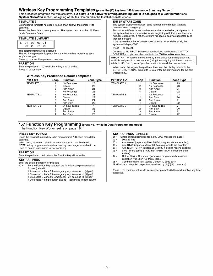
Wireless Key Programming Templates (press the [D] key from *58 Menu mode Summary Screen) This procedure programs the wireless keys, but a key is not active for arming/disarming until it is assigned to a user number (see System Operation section, Assigning Attributes Command in the Installation Instructions).
TEMPLATE ? Enter desired template number 1–6 (see chart below), then press [∗] to continue. To exit the Template screen, press [#]. The system returns to the *58 Menu mode Summary Screen.
TEMPLATE SUMMARY
L 01 02 03 04 T 23 22 21 23
The selected template is displayed. The top line represents loop numbers, the bottom line represents each loop’s zone type. Press [∗] to accept template and continue.
PARTITION Enter the partition (1, 2) in which the key is to be active. Press [∗] to continue.
ENTER START ZONE The system displays the lowest zone number of the highest available consecutive 4-zone group. To start at a different zone number, enter the zone desired, and press [∗]. If the system has four consecutive zones beginning with that zone, the zone number is displayed. If not, the system will again display a suggested zone that can be used. If the required number of consecutive zones is not available at all, the system will display “00”.
Press [∗] to accept.
Continue to the INPUT S/N (serial number/loop number) and XMIT TO CONFIRM prompts described earlier in the *56 Menu Mode section.
IMPORTANT: When confirmed, the key is not active for arming/disarming until it is assigned to a user number (using the assigning attributes command, attribute “4”). See System Operation section in Installation Instructions.
When done, the keypad beeps three times and the display returns to the ENTER START ZONE prompt to let you enter the starting zone for the next wireless key.
Wireless Key Predefined Default Templates For 5804 Loop Function Zone Type For 5804BD Loop Function Zone Type TEMPLATE 1 1 No Response 23 TEMPLATE 4 1 No Response 23 2 Disarm 22 2 No Response 23 3 Arm Away 21 3 Arm Away 21 4 No Response 23 4 Disarm 22 TEMPLATE 2 1 No Response 23 TEMPLATE 5 1 No Response 23 2 Disarm 22 2 Arm Stay 20 3 Arm Away 21 3 Arm Away 21 4 Arm Stay 20 4 Disarm 22 TEMPLATE 3 1 24-hour audible 7 TEMPLATE 6 1 24-hour audible 7 2 Disarm 22 2 Arm Stay 20 3 Arm Away 21 3 Arm Away 21 4 Arm Stay 20 4 Disarm 22
*57 Function Key Programming (press ∗∗∗∗57 while in Data Programming mode) The Function Key Worksheet is on page 19.
PRESS KEY TO PGM Press the desired function key to be programmed, A-D, then press [∗] to continue. When done, press 0 to exit this mode and return to data field mode. NOTE: A key programmed as a function key is no longer available to be used as an end-user macro key or panic key.
PARTITION Enter the partition (1-3) in which this function key will be active.
KEY "A" FUNC Enter the desired function for this key: 00 = For the Function key selected, the functions are pre-defined as
follows (default): If A selected = Zone 95 (emergency key, same as [1] [∗] pair) If B selected = Zone 99 (emergency key, same as [∗] [#] pair) If C selected = Zone 96 (emergency key, same as [3] [#] pair) If D selected = Single-button paging (continued in next column)
KEY "A" FUNC (continued) 01 = Single-button paging (sends a 999-9999 message to pager) 02 = Display time 03 = Arm AWAY (reports as User 00 if closing reports are enabled) 04 = Arm STAY (reports as User 00 if closing reports are enabled) 05 = Arm NIGHT-STAY (reports as User 00 if closing reports enabled) 06 = Step Arming (arms STAY, then NIGHT-STAY if enabled, then
AWAY) 07 = Output Device Command (for device programmed as system
operation type 66 in *80 Menu Mode) 08 = Communication Test (sends Contact ID code 601) 09 -12= Macro Keys 1-4 respectively (defined by [#] [6] [6] command) Press [∗] to continue; returns to key number prompt with the next function key letter displayed.
– 9 –
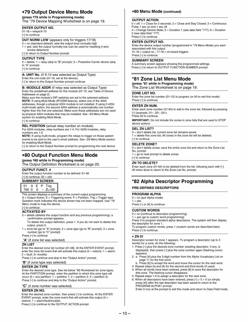
∗∗∗∗79 Output Device Menu Mode (press ∗∗∗∗79 while in Programming mode) The *79 Device Mapping Worksheet is on page 19.
ENTER OUTPUT NO. 01-18 = relays/X-10 [∗] to continue
OUT NORM LOW (appears only for triggers 17/18) 0 = no (standard default); sets the output level normally high 1 = yes; sets the output normally low (can be used for resetting 4-wire
smoke detectors) [∗] to return to Output Number prompt
OUTPUT TYPE 0 = delete; 1 = relay (skip to “B” prompt); 2 = Powerline Carrier device (skip to “A” prompt) [∗] to continue.
A: UNIT No. (if X-10 was selected as Output Type) Enter the unit code (01-16, set at the device). [∗] to return to the Output Number prompt continue
B: MODULE ADDR (if relay was selected as Output Type) Enter the predefined address for this module (07-15; see Table of Device Addresses on page 2). Make sure the module’s DIP switches are set to the selected address. NOTE: If using Multi-Mode (IP/GSM feature), select one of the 4204 addresses, though a physical 4204 module is not installed. If using 2-4204 multi-mode option, the second 4204 address is automatically one number higher than the first one selected. Make sure these addresses are not used by physical 4204 modules that may be installed. See ∗29 Menu Mode section for enabling Multi-Mode. [∗] to continue
REL POSITION (actual relay number on module) For 4204 modules, relay numbers are 1-4. For 4229 modules, relay numbers are 1-2. NOTE: If using multi-mode, program the relays to trigger on those system events to be sent to the user’s email address. See ∗29 Menu Mode section for enabling Multi-Mode. [∗] to return to the Output Number prompt for programming the next device
∗∗∗∗80 Output Function Menu Mode (press ∗∗∗∗80 while in Programming mode) The Output Definition Worksheet is on page 20.
OUTPUT FUNCT. # Enter the output function number to be defined: 01-48 [∗] to continue; 00 = exit
SUMMARY SCREEN
01 A E P Trig ?00 0 0 – ZL=00
This screen displays a summary of the current output programming A = Output Action; E = Triggering event; P = Partition; Trig = Trigger type Question mark indicates the device shown has not been mapped. Use *79 Menu mode to map the device. [∗] to continue
ACTIVATED BY 0 = delete (deletes the output function and any previous programming); a
confirmation prompt appears. To delete this output definition, press 1. If you do not want to delete this output, press 0.
1 = zone list (go to “A” prompt); 2 = zone type (go to “B” prompt); 3 = zone number (go to “C” prompt)
Press [∗] to continue
“A” (if zone list was selected)
ZN LIST Enter the desired zone list number (01-08). At the ENTER EVENT prompt, enter the zone list event that will activate this output (0 = restore; 1 = alarm; 2 = fault; 3= trouble) Press [∗] to continue and skip to the “Output Action” prompt.
“B” (if zone type was selected)
ENTER ZN TYPE Enter the desired zone type. See list below *80 Worksheet for zone types. At the PARTITION prompt, enter the partition in which this zone type will occur (0 = any partition; 1 = partition 1; 2 = partition 2; 3 = partition 3). Press [∗] to continue and skip to the “Output Action” prompt.
“C” (if zone number was selected)
ENTER ZN NO. Enter the desired zone number, then press [∗] to continue. At the ENTER EVENT prompt, enter the zone event that will activate this output (0 = restore; 1 = alarm/fault/trouble). Press [∗] to continue to the OUTPUT ACTION prompt
∗∗∗∗80 Menu Mode (continued) OUTPUT ACTION 0 = off; 1 = Close for 2 seconds; 2 = Close and Stay Closed; 3 = Continuous Pulse 1 sec on and 1 sec off 4 = Change Device State; 5 = Duration 1 (see data field *177); 6 = Duration 2 (see data field *177) Press [∗] to continue.
ENTER OUTPUT NO. Enter the device output number (programmed in *79 Menu Mode) you want associated with this output. 01-16 = output no.; 17-18 = on-board triggers Press [∗] to continue.
SUMMARY SCREEN A summary screen appears showing the programmed settings. Press [∗] to return to OUTPUT FUNCTION NUMBER prompt.
*81 Zone List Menu Mode (press *81 while in Programming mode) The Zone List Worksheet is on page 19.
ZONE LIST NO. Enter the zone list number (01-12) to program (or 00 to exit this mode). Press [∗] to continue.
ENTER ZN NUM. Enter each zone number (01-64) to add to the zone list, followed by pressing [∗] (example, 01∗, 02∗, 03∗). Press 00 to continue.
IMPORTANT: Do not include fire zones in zone lists that are used to STOP device actions.
DEL ZN LIST? 0 = don’t delete list; current zone list remains saved 1 = delete this zone list; All zones in the zone list will be deleted. [∗] to continue
DELETE ZONE? 0 = don’t delete zones; save the entire zone list and return to the Zone List No. prompt 1 = go to next prompt to delete zones [∗] to continue
ZN TO DELETE? Enter each zone (01-64) to be deleted from the list, following each with [∗]. 00 when done to return to the Zone List No. prompt.
*82 Alpha Descriptor Programming
PRE-DEFINED DESCRIPTORS
PROGRAM ALPHA 0 = no (quit Alpha mode) 1 = yes Press [∗] or [#] to continue.
CUSTOM WORDS 0 = no (continue to descriptor programming) 1 = yes (go to custom word programming) Press 0 to program standard alpha descriptors. The system will then display the descriptor for zone 1. To program custom words, press 1 (custom words are described later). Press [∗] to continue.
∗∗∗∗ ZN 01 Descriptor screen for zone 1 appears. To program a descriptor (up to 3 words) for a zone, do the following: 1. Press [∗] plus the desired zone number (existing descriptor, if any, is
displayed), then press [∗] plus the zone number again (flashing cursor appears).
2. a. Press [#] plus the 3-digit number from the Alpha Vocabulary List on page 11 for the first word.
b. Press [6] to accept the word and move the cursor for the next word. 3. Repeat steps 2a and 2b for the second and third words (if used). 4. When all words have been entered, press [8] to save the descriptor for
that zone. The flashing cursor disappears. 5. Repeat steps 1-4 to assign a descriptor for the next zone. 6. When all descriptors have been entered, press [∗] + 0 + 0 (or simply
press [#]) after the last descriptor has been saved to return to the PROGRAM ALPHA? prompt.
Enter 0 (no) at the prompt to exit this mode and return to Data Field mode.
– 10 –
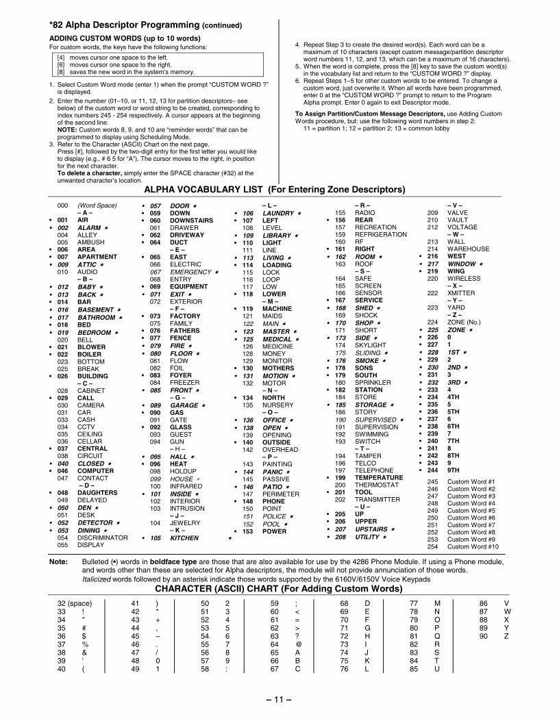
*82 Alpha Descriptor Programming (continued)
ADDING CUSTOM WORDS (up to 10 words) For custom words, the keys have the following functions:
[4] moves cursor one space to the left. [6] moves cursor one space to the right. [8] saves the new word in the system's memory.
1. Select Custom Word mode (enter 1) when the prompt “CUSTOM WORD ?” is displayed.
2. Enter the number (01–10, or 11, 12, 13 for partition descriptors– see below) of the custom word or word string to be created, corresponding to index numbers 245 - 254 respectively. A cursor appears at the beginning of the second line.
NOTE: Custom words 8, 9, and 10 are “reminder words” that can be programmed to display using Scheduling Mode.
3. Refer to the Character (ASCII) Chart on the next page. Press [#], followed by the two-digit entry for the first letter you would like
to display (e.g., # 6 5 for “A”). The cursor moves to the right, in position for the next character.
To delete a character, simply enter the SPACE character (#32) at the unwanted character’s location.
4. Repeat Step 3 to create the desired word(s). Each word can be a
maximum of 10 characters (except custom message/partition descriptor word numbers 11, 12, and 13, which can be a maximum of 16 characters).
5. When the word is complete, press the [8] key to save the custom word(s) in the vocabulary list and return to the “CUSTOM WORD ?” display.
6. Repeat Steps 1–5 for other custom words to be entered. To change a custom word, just overwrite it. When all words have been programmed, enter 0 at the “CUSTOM WORD ?” prompt to return to the Program Alpha prompt. Enter 0 again to exit Descriptor mode.
To Assign Partition/Custom Message Descriptors, use Adding Custom Words procedure, but: use the following word numbers in step 2: 11 = partition 1; 12 = partition 2; 13 = common lobby
ALPHA VOCABULARY LIST (For Entering Zone Descriptors)
000 (Word Space) – A – • 001 AIR • 002 ALARM ∗∗∗∗ 004 ALLEY 005 AMBUSH • 006 AREA • 007 APARTMENT • 009 ATTIC ∗∗∗∗ 010 AUDIO – B – • 012 BABY ∗∗∗∗ • 013 BACK ∗∗∗∗ • 014 BAR • 016 BASEMENT ∗∗∗∗ • 017 BATHROOM ∗∗∗∗ • 018 BED • 019 BEDROOM ∗∗∗∗ 020 BELL • 021 BLOWER • 022 BOILER 023 BOTTOM 025 BREAK • 026 BUILDING – C – 028 CABINET • 029 CALL 030 CAMERA 031 CAR 033 CASH 034 CCTV 035 CEILING 036 CELLAR • 037 CENTRAL 038 CIRCUIT • 040 CLOSED ∗∗∗∗ • 046 COMPUTER 047 CONTACT – D – • 048 DAUGHTERS 049 DELAYED • 050 DEN ∗∗∗∗ 051 DESK • 052 DETECTOR ∗∗∗∗ • 053 DINING ∗∗∗∗ 054 DISCRIMINATOR 055 DISPLAY
• 057 DOOR ∗∗∗∗ • 059 DOWN • 060 DOWNSTAIRS 061 DRAWER • 062 DRIVEWAY • 064 DUCT – E – • 065 EAST 066 ELECTRIC 067 EMERGENCY ∗∗∗∗ 068 ENTRY • 069 EQUIPMENT • 071 EXIT ∗∗∗∗ 072 EXTERIOR – F – • 073 FACTORY 075 FAMILY • 076 FATHERS • 077 FENCE • 079 FIRE ∗∗∗∗ • 080 FLOOR ∗∗∗∗ 081 FLOW 082 FOIL • 083 FOYER 084 FREEZER • 085 FRONT ∗∗∗∗ – G – • 089 GARAGE ∗∗∗∗ • 090 GAS 091 GATE • 092 GLASS 093 GUEST 094 GUN – H – • 095 HALL ∗∗∗∗ • 096 HEAT 098 HOLDUP 099 HOUSE ∗ 100 INFRARED • 101 INSIDE ∗∗∗∗ 102 INTERIOR 103 INTRUSION – J – 104 JEWELRY – K – • 105 KITCHEN ∗∗∗∗
– L – • 106 LAUNDRY ∗∗∗∗ • 107 LEFT 108 LEVEL • 109 LIBRARY ∗∗∗∗ • 110 LIGHT 111 LINE • 113 LIVING ∗∗∗∗ • 114 LOADING 115 LOCK 116 LOOP 117 LOW • 118 LOWER – M – • 119 MACHINE 121 MAIDS 122 MAIN ∗∗∗∗ • 123 MASTER ∗∗∗∗ • 125 MEDICAL ∗∗∗∗ 126 MEDICINE 128 MONEY 129 MONITOR • 130 MOTHERS • 131 MOTION ∗∗∗∗ 132 MOTOR – N – • 134 NORTH 135 NURSERY – O – • 136 OFFICE ∗∗∗∗ • 138 OPEN ∗∗∗∗ 139 OPENING • 140 OUTSIDE 142 OVERHEAD – P – 143 PAINTING • 144 PANIC ∗∗∗∗ 145 PASSIVE • 146 PATIO ∗∗∗∗ 147 PERIMETER • 148 PHONE 150 POINT 151 POLICE ∗∗∗∗ 152 POOL ∗∗∗∗ • 153 POWER
– R – 155 RADIO • 156 REAR 157 RECREATION 159 REFRIGERATION 160 RF • 161 RIGHT • 162 ROOM ∗∗∗∗ 163 ROOF – S – 164 SAFE 165 SCREEN 166 SENSOR • 167 SERVICE • 168 SHED ∗∗∗∗ 169 SHOCK • 170 SHOP ∗∗∗∗ 171 SHORT • 173 SIDE ∗∗∗∗ 174 SKYLIGHT 175 SLIDING ∗∗∗∗ • 176 SMOKE ∗∗∗∗ • 178 SONS • 179 SOUTH 180 SPRINKLER • 182 STATION 184 STORE • 185 STORAGE ∗∗∗∗ 186 STORY 190 SUPERVISED ∗∗∗∗ 191 SUPERVISION 192 SWIMMING 193 SWITCH – T – 194 TAMPER 196 TELCO 197 TELEPHONE • 199 TEMPERATURE 200 THERMOSTAT • 201 TOOL 202 TRANSMITTER – U – • 205 UP • 206 UPPER • 207 UPSTAIRS ∗∗∗∗ • 208 UTILITY ∗∗∗∗
– V – 209 VALVE 210 VAULT 212 VOLTAGE – W – 213 WALL 214 WAREHOUSE • 216 WEST • 217 WINDOW ∗∗∗∗ • 219 WING 220 WIRELESS – X – 222 XMITTER – Y – 223 YARD – Z – 224 ZONE (No.) • 225 ZONE ∗∗∗∗ • 226 0 • 227 1 • 228 1ST ∗∗∗∗ • 229 2 • 230 2ND ∗∗∗∗ • 231 3 • 232 3RD ∗∗∗∗ • 233 4 • 234 4TH • 235 5 • 236 5TH • 237 6 • 238 6TH • 239 7 • 240 7TH • 241 8 • 242 8TH • 243 9 • 244 9TH
245 Custom Word #1 246 Custom Word #2 247 Custom Word #3 248 Custom Word #4 249 Custom Word #5 250 Custom Word #6 251 Custom Word #7 252 Custom Word #8 253 Custom Word #9 254 Custom Word #10
Note: Bulleted (•) words in boldface type are those that are also available for use by the 4286 Phone Module. If using a Phone module, and words other than these are selected for Alpha descriptors, the module will not provide annunciation of those words.
Italicized words followed by an asterisk indicate those words supported by the 6160V/6150V Voice Keypads CHARACTER (ASCII) CHART (For Adding Custom Words)
32 (space) 33 ! 34 " 35 # 36 $ 37 % 38 & 39 ' 40 (
41 ) 42 * 43 + 44 , 45 – 46 . 47 / 48 0 49 1
50 2 51 3 52 4 53 5 54 6 55 7 56 8 57 9 58 :
59 ; 60 < 61 = 62 > 63 ? 64 @ 65 A 66 B 67 C
68 D 69 E 70 F 71 G 72 H 73 I 74 J 75 K 76 L
77 M 78 N 79 O 80 P 81 Q 82 R 83 S 84 T 85 U
86 V 87 W 88 X 89 Y 90 Z
– 11 –
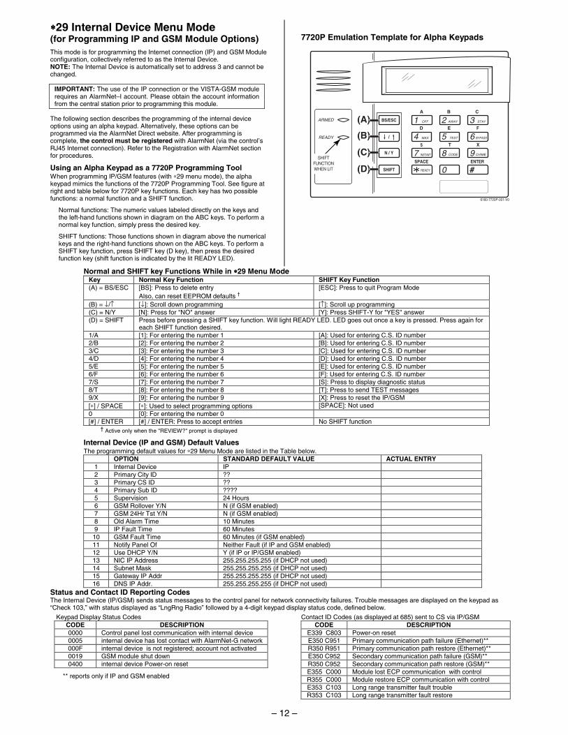
∗∗∗∗29 Internal Device Menu Mode (for Programming IP and GSM Module Options)
This mode is for programming the Internet connection (IP) and GSM Module configuration, collectively referred to as the Internal Device. NOTE: The Internal Device is automatically set to address 3 and cannot be changed.
IMPORTANT: The use of the IP connection or the VISTA-GSM module requires an AlarmNet–I account. Please obtain the account information from the central station prior to programming this module.
The following section describes the programming of the internal device options using an alpha keypad. Alternatively, these options can be programmed via the AlarmNet Direct website. After programming is complete, the control must be registered with AlarmNet (via the control’s RJ45 Internet connection). Refer to the Registration with AlarmNet section for procedures.
Using an Alpha Keypad as a 7720P Programming Tool When programming IP/GSM features (with ∗29 menu mode), the alpha keypad mimics the functions of the 7720P Programming Tool. See figure at right and table below for 7720P key functions. Each key has two possible functions: a normal function and a SHIFT function.
Normal functions: The numeric values labeled directly on the keys and the left-hand functions shown in diagram on the ABC keys. To perform a normal key function, simply press the desired key.
SHIFT functions: Those functions shown in diagram above the numerical keys and the right-hand functions shown on the ABC keys. To perform a SHIFT key function, press SHIFT key (D key), then press the desired function key (shift function is indicated by the lit READY LED).
7720P Emulation Template for Alpha Keypads
1 OFF
4 MAX
7 INSTANT
READY
2 AWAY
5 TEST
8 CODE
0
3 STAY
6 BYPASS
9 CHIME
(B)
A
D
S
ENTER
SHIFT
N / Y
/
BS/ESC
SPACE
B
E
T
C
F
X
#
ARMED
READY
6160-7720P-001-V0
SHIFTFUNCTIONWHEN LIT
(C)
(D)
(A)
Normal and SHIFT key Functions While in ∗∗∗∗29 Menu Mode Key Normal Key Function SHIFT Key Function (A) = BS/ESC [BS]: Press to delete entry [ESC]: Press to quit Program Mode Also, can reset EEPROM defaults †
(B) = ↓/↑ [↓]: Scroll down programming [↑]: Scroll up programming (C) = N/Y [N]: Press for "NO" answer [Y]: Press SHIFT-Y for "YES" answer (D) = SHIFT Press before pressing a SHIFT key function. Will light READY LED. LED goes out once a key is pressed. Press again for
each SHIFT function desired. 1/A [1]: For entering the number 1 [A]: Used for entering C.S. ID number 2/B [2]: For entering the number 2 [B]: Used for entering C.S. ID number 3/C [3]: For entering the number 3 [C]: Used for entering C.S. ID number 4/D [4]: For entering the number 4 [D]: Used for entering C.S. ID number 5/E [5]: For entering the number 5 [E]: Used for entering C.S. ID number 6/F [6]: For entering the number 6 [F]: Used for entering C.S. ID number 7/S [7]: For entering the number 7 [S]: Press to display diagnostic status 8/T [8]: For entering the number 8 [T]: Press to send TEST messages 9/X [9]: For entering the number 9 [X]: Press to reset the IP/GSM [∗] / SPACE [∗]: Used to select programming options [SPACE]: Not used 0 [0]: For entering the number 0 [#] / ENTER [#] / ENTER: Press to accept entries No SHIFT function
† Active only when the "REVIEW?" prompt is displayed
Internal Device (IP and GSM) Default Values The programming default values for ∗29 Menu Mode are listed in the Table below.
OPTION STANDARD DEFAULT VALUE ACTUAL ENTRY 1 Internal Device IP 2 Primary City ID ?? 3 Primary CS ID ?? 4 Primary Sub ID ???? 5 Supervision 24 Hours 6 GSM Rollover Y/N N (if GSM enabled) 7 GSM 24Hr Tst Y/N N (if GSM enabled) 8 Old Alarm Time 10 Minutes 9 IP Fault Time 60 Minutes 10 GSM Fault Time 60 Minutes (if GSM enabled) 11 Notify Panel Of Neither Fault (if IP and GSM enabled) 12 Use DHCP Y/N Y (if IP or IP/GSM enabled) 13 NIC IP Address 255.255.255.255 (if DHCP not used) 14 Subnet Mask 255.255.255.255 (if DHCP not used) 15 Gateway IP Addr 255.255.255.255 (if DHCP not used) 16 DNS IP Addr. 255.255.255.255 (if DHCP not used)
Status and Contact ID Reporting Codes The Internal Device (IP/GSM) sends status messages to the control panel for network connectivity failures. Trouble messages are displayed on the keypad as “Check 103,” with status displayed as “LngRng Radio” followed by a 4-digit keypad display status code, defined below.
Keypad Display Status Codes CODE DESCRIPTION 0000 Control panel lost communication with internal device 0005 internal device has lost contact with AlarmNet-G network 000F internal device is not registered; account not activated 0019 GSM module shut down 0400 internal device Power-on reset
** reports only if IP and GSM enabled
Contact ID Codes (as displayed at 685) sent to CS via IP/GSM CODE DESCRIPTION
E339 C803 Power-on reset E350 C951 Primary communication path failure (Ethernet)** R350 R951 Primary communication path restore (Ethernet)** E350 C952 Secondary communication path failure (GSM)** R350 C952 Secondary communication path restore (GSM)** E355 C000 Module lost ECP communication with control R355 C000 Module restore ECP communication with control E353 C103 Long range transmitter fault trouble R353 C103 Long range transmitter fault restore
– 12 –
Using ∗∗∗∗29 Menu Mode to Program IP/GSM Options Entering ∗∗∗∗29 Program Mode Press ∗29 while in Data Field Programming mode. The following prompts appear.
Enable INT IP/GSM? 0 = No, not using either IP or GSM; 1 = Yes, using IP and/or GSM module [∗] to continue. NOTE: Default = 1 (IP and/or GSM)
IMPORTANT: If using an external communication device, see the VISTA-GSM Module Installation section of the Installation and Setup Guide (Inadequate Signal Strength paragraph) for physical installation of an external communication device. When complete, enter 1 at this prompt and enter 1-Prog at the next prompt. Then program and register the external device using the Installation and Setup Guide included with the external communication device.
Programming/Diagnostics Select 1= Prog (program the IP/GSM options) 2 = Diag (enter diagnostic mode) 0 = Quit; returns to data field programming mode
Internal Device Programming Prompts The keys used to select and enter options now follow 7720P keypad emulation. Refer to the table on the previous page for detailed key functions. The following is a summary:
[∗] = scroll the options of a particular prompt [#] = accept the entry and move to the next prompt [A] = backspace or shift-[A} for escape [B] = scroll to next prompt or shift-[B] scroll to previous prompt [C] = answer No or shift-[C] answer Yes to prompt [D] = shift key
Internal Device Selection Select the type of IP and/or GSM module usage (press [∗] to scroll choices): Disabled (none); IP only; GSM module only; IP & GSM [#] to continue
NOTE IF USING GSM ONLY OPTION: For registration purposes, the internal device must first be set for IP & GSM (and the control must be connected to the Internet via the RJ45 connector). Follow the prompts to program appropriate values and use the default settings for the IP specific prompts. After the control is registered (see Registering the Control with AlarmNet paragraph later in this section), return to this prompt and set for GSM only.
Multi-Mode (email reporting) This feature is available only after authorization for it is set via the web-based programming tool on the AlarmNet Direct website. Multi-mode emulates 4204 Relay Module outputs to send up to four (4204 sourced) or up to eight (2-4204 sourced) reports of system events to the user via email (email address is entered at the AlarmNet Direct website). Use the AlarmNet Direct website to customize event titles, if desired. If enabled, a multi-mode address must be entered in the next prompt. Use *79/*80 Menu modes to program each emulated output to trigger a desired system event that, upon occurrence, will be sent to the user’s email address. Select the desired multi mode option: Disabled = no email reporting of events 4204 Sourced = up to four types of events reported (relay numbers 1-4 report
as events 1-4 respectively) 2-4204 Sourced = up to eight types of events reported (first module’s relay
numbers 1-4 report as events 1-4 respectively; second module’s relay numbers 1-4 report as events 5-8 respectively)
To scroll the choices: [∗] key scrolls forward; [backspace] key scrolls backward [#] to continue NOTES: 1. Multi-mode has not been evaluated by UL. 2. Multi-mode (email notification) is intended as a convenience for the user,
and does not replace Central Station reporting of critical events (alarms, troubles, etc.).
Multi-Mode Address This prompt appears if Multi Mode is enabled. 12-15 =emulated 4204 Relay Module address. If using “2-4204-sourced,” the address of the second module is automatically assigned an address one higher than the first module’s address. NOTE: A 4204 Relay module address is required for multi-mode purposes, but an actual 4204 Relay module is not used.
Primary City ID NOTE: Account information is provided by the central station administrator. 01-99 (decimal) = 2-digit primary city code
Primary CS ID Enter the primary central station's system ID number, 01-FE (HEX)
Primary Sub ID Enter the 4-digit customer account number, 0001-9999 (decimal).
Remote Access This feature is available only after authorization for it is set via the web-based programming tool on the AlarmNet Direct website. Remote Services allow the end user to access their security system from a computer via the remote services website. Most system functions can then be performed. [Y] = use remote services [N] = do not use remote services [#] to continue
Keypad Address (for Remote Access) This prompt appears if remote access is enabled. For enhanced remote access features, choose an AUI address. If no AUI addresses are available (all four AUIs are being used), choose an available standard keypad address (some remote access features will be unavailable). 1, 2, 5, 6 = emulated AUI address 17-23 = emulated standard keypad address NOTE: An AUI or standard keypad address is required for remote access purposes, but an actual AUI device or keypad is not used.
Supervision The supervising station must hear from the IP/GSM at least once during the supervision period. AlarmNet transmits a communications failure alarm to the central station if the supervision message is not received within the period.
This selection sets the supervision timing for one of the following values: if using IP and/or GSM if using IP only (not for GSM usage) • 30 day • US UL Line (6 Min) • 24-hours • US UL Line (90 Sec) • None (no supervision) • CN UL Line Lv1 3 (3 Min) • CN UL Line Lv1 4 (90 Sec) • CN UL Line Lv1 5 (75 Sec) • 1 hour To scroll the choices: [∗] key scrolls forward; [backspace] key scrolls backward [#] to continue
GSM Rollover Y/N Appears only if IP&GSM is selected as Internal Device option. [Y] = all messages (including AlarmNet network supervisory messages) are
sent over the GSM network in the event of an Internet failure [N] = all messages (except AlarmNet network supervisory messages) are sent
automatically over the GSM network in the event of an Internet failure
GSM 24Hr Tst Y/N Appears only if IP&GSM is selected as Internal Device option. [Y] = have a message sent once a day to verify GSM operation. A "secondary
communication path loss" message is generated if the message is not successfully delivered.
[N] = disable 24hr test
Old Alarm Time The old alarm time sets how long an undeliverable alarm is retried for delivery to AlarmNet. If the message is not validated, it is retried until the old alarm time is reached or the message is validated. The choices available are: • 10 Minutes • 4 Hours • 15 Minutes • 8 Hours • 30 Minutes • 12 Hours • 1 Hour • 24 Hours • 2 Hours To scroll the choices: [∗] key scrolls forward; [backspace] key scrolls backward [#] to continue
IP Fault Time Appears only if IP or IP&GSM is selected as Internal Device option. 01-99 = time delay (in minutes) before the control notifies the central station that
there is a loss of contact with the network over the Ethernet (IP) connection.
0 = no delay (valid only If using IP only) Must be two (2) minutes for UL installations.
GSM Flt Time Appears only if GSM or IP&GSM is selected as Internal Device option. 01-99 = time delay (in minutes) before the control notifies the central station
that a loss of contact with AlarmNet network has occurred. 0 = no delay (valid only if using GSM only, Must be two (2) minutes for UL installations.
Notify Panel Of _ Appears only if IP&GSM is selected as Internal Device option. Select from the following choices: • Neither Fault • Both IP and GSM must fail before fault code is sent (status code 4005
displayed); panel receives primary and secondary path failure messages. No message sent if only one or the other path fails.
To scroll the choices: [∗] key scrolls forward; [backspace] key scrolls backward [#] to continue
NOTE: IP failure will always be sent to the central station as Primary Path Failure, and GSM failure will always be sent as Secondary Path Failure.
IP address information prompts The following prompts appear only if IP or IP&GSM is selected as Internal Device. It is recommended to use dynamically allocated IP addresses, but if fixed IP addresses are desired, contact your network administrator for the appropriate information. Note that a valid IP address must be entered in each prompt before the system continues to the next prompt. Entries cannot be left with the default values.
Use DHCP [Y] = have the IP addresses dynamically allocated (recommended), skip to
Review prompt. [N] = use fixed IP addresses; continue with next prompt [#] to continue
– 13 –
NIC IP Address [255.255.255.255] Enter the 4-part IP address for this device, separating each part with a space ([∗] key, displayed as periods). [#] to continue
Subnet Mask [255.255.255.255] Enter the 32-bit address mask used to indicate the portion (bits) of the IP address that is being used for the subnet address, separating each part with a space ([∗] key, displayed as periods). [#] to continue
Gateway IP Addr [255.255.255.255] Enter the 4-part IP address assigned to the Gateway, separating each part with a space ([∗] key, displayed as periods). If unused set to 0.0.0.0. [#] to continue
DNS IP Addr [255.255.255.255] Enter the 4-part IP address assigned to the DNS (Domain Name System) server, separating each part with a space ([∗] key, displayed as periods). If unused set to 0.0.0.0. [#] to continue
Review? (and Exit ∗∗∗∗29 Menu mode or Reset Defaults) You can review the ∗29 Menu mode options to ensure that the correct entries have been made. When satisfied, select [N] to exit ∗29 Menu mode. To review prompts or exit ∗∗∗∗29 Menu mode: [Y] = review prompts and entries, starting with Internal Device. Use the
up/down arrow keys to scroll through the program fields without changing any of the values. If a value requires change, simply type in the correct value. When the last field is displayed, the “REVIEW?” prompt appears.
[N] = Exit *29 menu mode and return to data field programming mode. The prompt briefly displays “DONE” before returning to data field mode prompt “Enter ∗ or #.”
[#] to accept Y or N selection (# alone exits same as N)
To reset ∗∗∗∗29 Menu mode defaults: Press [ESC] at the Review prompt to display the “Set Defaults” prompt. [Y] = reset ∗29 menu mode options to factory values; if selected, all
programmed ∗29 Menu mode options are reset to the factory settings [N] = cancel reset defaults function
Programming IP/GSM Options via AlarmNet Direct Website To program the IP/GSM options via the AlarmNet Direct website (if you are already signed up for this service), go to: https://services.alarmnet.com/AlarmNetDirect/userlogin.aspx If you are not signed up for this service, click on “Dealer Sign-Up. Log in and follow the on-screen prompts. Please have the following information available: 1. Primary City ID (two-digit number) 2. Primary Central Station ID (two-digit hexadecimal number) 3. Primary Subscriber ID (four-digit number) 4. MAC ID and MAC CRC number (located on the outside of box and on label
inside module) or MIN number of the device you are replacing 5. Mode of operation of existing module if replacing a "C" series radio. After programming is complete, you must transfer the data to the module and the module must be registered. Refer to the Registration section for details.
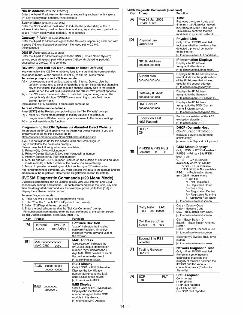
IP/GSM Diagnostic Commands (∗∗∗∗29 Menu Mode) Diagnostic commands can be used to quickly view your Internet and GSM connectivity settings and options. For each command press the [shift] key and then the designated command key. For example, press [shift] then [1/A] to display the software revision screen.
To enter Diagnostic mode: 1. Press ∗29 while in data field programming mode. 2. Enter “1” at the “Enable IP/GSM” prompt then press [∗]. 3. Select “2” (Diag) at the next prompt. 4. Enter the desired command at the “Sel Key Command” prompt. For subsequent commands, enter the next command at the current screen. To exit Diagnostic mode, press ESC (shift-[A]).
Key Prompt Function
[A]
Internal IP/GSM x.x.xx mm/dd/yy
Software Revision "x.x.xx" indicates the installed software Revision. Mm/dd/yy indicates month, day and year of the revision.
[B]
MAC xxxxxxxxxxxx MAC CRC yyyy
MAC Address “xxxxxxxxxxxx” indicates the IP/GSM’s unique identification number. Yyyy indicates the 4 digit MAC CRC needed to enroll the device in dealer direct. [∗] to continue to SCID.
SCID xxxxx xxxxx xxxxx xxxxx
SCID Display Only if GSM or IP/GSM enabled. Displays the identification number assigned to the SIM card (SCID) in this device. [∗] to continue to IMEI.
IMEI xxxxxxxx Xxxxxx x
IMEI Display Only if GSM or IP/GSM enabled. Displays the identification number assigned to the GSM module in this device. [∗] returns to MAC Address.
IP/GSM Diagnostic Commands (continued) Key Prompt Function
[C]
Mon 01 Jan 2006 05:48:39 am
Time Retrieves the current date and time from the AlarmNet network in Greenwich Mean Time (GMT). This display confirms that the module is in sync with network.
[D]
Physical Link Good/Bad
Physical Link Only if IP or IP/GSM enabled. Indicates whether the device has detected a physical connection to the internet. [∗] to continue to NIC IP address.
NIC IP Address xxx.xxx.xxx.xxx
IP Information Displays Displays the IP address assigned to this device. [∗] to continue to subnet mask.
Subnet Mask xxx.xxx.xxx.xxx
Displays the 32-bit address mask used to indicate the portion (bits) of the IP Address that is being used for the subnet address. [∗] to continue to gateway IP.
Gateway IP Addr xxx.xxx.xxx.xxx
Displays the IP Address assigned to the Gateway. [∗] to continue to DNS server IP.
DNS Serv IP xxx.xxx.xxx.xxx
Displays the IP Address assigned to the DNS (Domain Name System) server. [∗] to continue to encryption test.
Encryption Test AES Passed!
Performs a self-test of the AES encryption algorithm. [∗] to continue to DHCP.
DHCP OK
DHCP (Dynamic Host Configuration Protocol) indicates server is performing satisfactorily. [∗] returns to Physical Link prompt.
[E]
PriRSSI GPRS REG -xxxdbm x x
GSM Status Displays Only if GSM or IP/GSM enabled. PriRSSI – Primary Site RSSI level in dbm GPRS – GPRS Service availability where “x” can be: “Y” if GPRS is available “N” if GPRS is Not available REG – Registration status from GSM module where “x” can be: N – Not Registered H – Registered Home S – Searching D – Registration Denied R – Registered Roaming ? – Unknown Reg. State [∗] to continue to next screen.
Cntry Netw LAC xxx xxx xxxxx
Cntry – Country Code Netw – Network Code LAC – Reg. status from GSM. [∗] to continue to next screen.
Cell BaseSt Chan Xxxxx x xxx
Cell – Base Station ID BaseSt – Base Station Antenna Sector Chan – Control Channel in use [∗] to continue to next screen.
Second Site RSSI -xxxdbm
Secondary GSM Site RSSI level in dbm. [∗] to continue to next screen.
[F]
Testing Gateway Redir 1
Network Diagnostic Test Only if IP or IP/GSM enabled. Performs a set of network diagnostics that tests the integrity of the links between the IP/GSM and the various connection points (Redirs) to AlarmNet.
[S]
ECP FLT OK
Status request OK = normal i = IP off line I = IP fault reported g = GSM off line G = GSM fault reported
– 14 –
IP/GSM Diagnostic Commands (continued)
Key Prompt Function
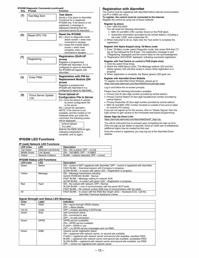
[T]
Test Msg Sent
Test Alarm Sends a Test alarm to AlarmNet. Functional for a registered IP/GSM only. If the device is not registered, a message is displayed indicating that the command cannot be executed.
[X]
Reset CPU Y/N
Reset the IP/GSM. [N] = return to diagnostic mode
(blank screen = enter next command or escape).
[Y] = resets the module (blank screen = when reset complete, enter next command or escape).
[↑↑↑↑]
Registering …
Registration (Shift-UP arrow) Registers a programmed IP/GSM with AlarmNet. If it is configured to report to AlarmNet, the IP/GSM will register with AlarmNet.
[↓↓↓↓]
Enter PIN#
Registration with PIN for Replacement Module (DN arrow) Registers a programmed IP/GSM with AlarmNet if it is configured to report to AlarmNet.
[0]
Force Server Update Y/N
Force Upload of Configuration File to Server[Y] = force the device to upload
its entire configuration file to the server.
[N] = cancel the operation. NOTE: If the internet is not available, and the module is not initialized when you enter this command, the following screen will be displayed:
Cannot Upload Try Later! _
Wait for the RSSI LEDs to light, indicating initialization is complete, and try again.
Registration with AlarmNet The control must be registered with AlarmNet before internet communication (via IP or GSM) can occur. To register, the control must be connected to the Internet. Register the control by using one of these methods:
Register by phone 1. Call 1-800-222-6525 You will need the following information: • MAC ID and MAC CRC number (found on the PCB label). • Subscriber information (provided by the central station), including a
city code, CSID, and a subscriber ID. 2. When instructed to do so, triple-click the Test switch to complete the
registration.
Register with Alpha Keypad using *29 Menu mode 1. Enter *29 Menu mode, select Diagnostic mode, then press Shift then [↑]
key (D key followed by the B key). The registration message is sent (“Registering” displayed) and the control waits for the acknowledgment.
2. “Registration SUCCESS” displayed, indicating successful registration.
Register with Test Switch on control’s PCB (triple-click) 1. Click the switch three times. 2. Watch the GSM Status LEDs: The Message (yellow) LED and the
Status (green) LED will blink slowly in unison while registration is in progress.
3. When registration is complete, the Status (green) LED goes out.
Register with AlarmNet Direct Website To register via AlarmNet Direct Website, please go to: https://services.alarmnet.com/AlarmNetDirect/userlogin.aspx.
Log in and follow the on-screen prompts.
Please have the following information available: • Primary City ID (two-digit number provided by central station) • Primary Central Station ID (two-digit hexadecimal number provided by
central station) • Primary Subscriber ID (four-digit number provided by central station) • MAC ID and MAC CRC number (located on outside of box and on label
on control’s PC board). If you are not signed up for this service, click on “Dealer Signup” from the login screen to gain access to the Honeywell web-based programming.
Dealer Sign-Up Direct Link: https://services.alarmnet.com/AlarmNetDirectP_Sign-Up.
You will be instructed how to proceed upon completing the sign-up form. Only one sign-up per dealer is required. Once an initial user is established, additional logins may be created by that user. Once the control is registered, you may log out of the AlarmNet Direct website.
IP/GSM LED Functions
IP (web) Network LED Functions LED Color LED Description Top Green Ethernet Link/Activity ON – link is active; OFF – no link Middle Green Link Speed ON – 100 MB/S; OFF – 10 MB/S Yellow Network Collision BLINK – collision detected; OFF – normal
IP/GSM Status LED Functions LED Color LED Description Green Status ON – control is NOT registered with AlarmNet; OFF – control is registered with AlarmNet.
FAST BLINK – Download session with Compass in progress. SLOW BLINK – In unison with yellow LED – Registration in progress.
Yellow Message ON – Message transmission pending. QUICK PERIODIC BLINK - Normal FAST BLINK – Message waiting for network ACK. SLOW BLINK – In unison with green LED – Registration in progress.
Red Fault ON – No contact with network; OFF– Normal. SLOW BLINK – Loss of communication with the panel (ECP fault). FAST BLINK – No network contact AND loss of communication with the panel.
All FAST BLINK – In unison with the RSSI Bar Graph LEDs – Hardware Error. Call the AlarmNet Technical Assistance Center.
Signal Strength and Status LED Meanings Color Label Indication Red RSSI ON = signal strength (RSSI) display
OFF = status display Yel (2) mode OFF = module operating in ECPmode Green Web web connection status
ON = connected to web OFF = no web connection
Green GPRS GPRS service availability ON = GPRS service available FLASH = GPRS in use OFF = no GPRS service (messages sent via SMS)
Green GSM network carrier registration status ON = registered with network carrier, no second site available FLASH = registered with network carrier and second site available, excellent RSSI BLINK = registered with network carrier and second site available, acceptable RSSI SLOW BLINK = registered with network carrier and second site available, low RSSI OFF = control not registered with network carrier
– 15 –
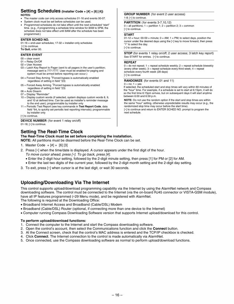
Setting Schedules (Installer Code + [#] + [6] [4]) NOTES: • The master code can only access schedules 01-16 and events 00-07. • System clock must be set before schedules can be used. • Programmed schedules do not take effect until the next scheduled “start”
time. (e.g., if programming a schedule time window for 8AM to 5PM, the schedule does not take effect until 8AM after the schedule has been programmed.)
ENTER SCHED NO. 01-16 = end-user schedules; 17-32 = installer-only schedules [∗] to continue. To Quit, enter 00.
ENTER EVENT 00 = clear event 01 = Relay On/Off 02 = User Access 03 = Latch Key Report to Pager (sent to all pagers in the user’s partition;
message sent is 777-7777. User must be enabled for paging and system must be armed before reporting can occur.)
04 = Forced Stay Arming (Forced bypass is automatically enabled regardless of setting in field *23)
05 = Forced Away Arming (Forced bypass is automatically enabled regardless of setting in field *23)
06 = Auto Disarm 07 = Display “Reminder” 10 = Display custom words (if selected, system displays custom words 8, 9,
and 10 at defined time. Can be used as installer’s reminder message to the end user); programmable by installer only
11 = Periodic Test Report (see key commands in Test Report Code, data field *64, to quickly set periodic test reporting intervals); programmable by installer only
[∗] to continue.
DEVICE NUMBER ( for event 1 relay on/off) 01-18; [∗] to continue.
GROUP NUMBER ( for event 2 user access) 1-8; [∗] to continue.
PARTITION ( for events 3-7,10,12) 0 = all partitions; 1 = partition 1; 2 = partition 2; 3 = common [∗] to continue.
START 01-12 = hour; 00-59 = minute; 0 = AM; 1 = PM; to select days, position the cursor under the desired days using the [∗] key to move forward, then press “1” to select the day. [∗] to continue.
STOP (for events 1 relay on/off; 2 user access; 3 latch key report) See START for entries. [∗] to continue.
REPEAT 0 = do not repeat; 1 = repeat schedule weekly; 2 = repeat schedule biweekly (every other week); 3 = repeat schedule every third week; 4 = repeat schedule every fourth week (28 days) [∗] to continue
RANDOMIZE (for events 01 and 11) 0 = no; 1 = yes If selected, the scheduled start and stop times will vary within 60 minutes of the “hour” time. For example, if a schedule is set to start at 6:15pm, it will do so the first time 6:15pm arrives, but on subsequent days it will start anytime between 6:00 and 6:59 p.m.
NOTE: Do not use the random option if the start and stop times are within the same “hour” setting, otherwise unpredictable results may occur (e.g., the randomized stop time may occur before the start time). [∗] to continue and return to ENTER SCHED NO. prompt to program the next schedule.
Setting The Real-Time Clock The Real-Time Clock must be set before completing the installation. NOTE: All partitions must be disarmed before the Real-Time Clock can be set.
1. Master Code + [#] + [6] [3]
2. Press [∗] when the time/date is displayed. A cursor appears under the first digit of the hour. To move cursor ahead, press [∗]. To go back, press [#]. • Enter the 2-digit hour setting, followed by the 2-digit minute setting, then press [1] for PM or [2] for AM. • Enter the last two digits of the current year, followed by the 2-digit month setting and the 2-digit day setting.
3. To exit, press [∗] when cursor is at the last digit, or wait 30 seconds.
Uploading/Downloading Via The Internet This control supports upload/download programming capability via the Internet by using the AlarmNet network and Compass downloading software. The control must be connected to the Internet (via the on-board RJ45 connector or VISTA-GSM module), have all IP features programmed (∗29 Menu mode), and be registered with AlarmNet. The following is required at the Downloading Office: • Broadband Internet Access and Broadband (Cable/DSL) Modem • Broadband (Cable/DSL) Router (optional, if connecting more than one device to the Internet) • Computer running Compass Downloading Software version that supports Internet upload/download for this control. To perform upload/download functions: 1. Connect the computer to the Internet and start the Compass downloading software. 2. Open the control’s account, then select the Communications function and click the Connect button. 3. At the Connect screen, check that the control’s MAC address is entered and the TCP/IP checkbox is checked. 4. Click Connect. The Internet connection to the control is made automatically via AlarmNet. 5. Once connected, use the Compass downloading software as normal to perform upload/download functions.
– 16 –
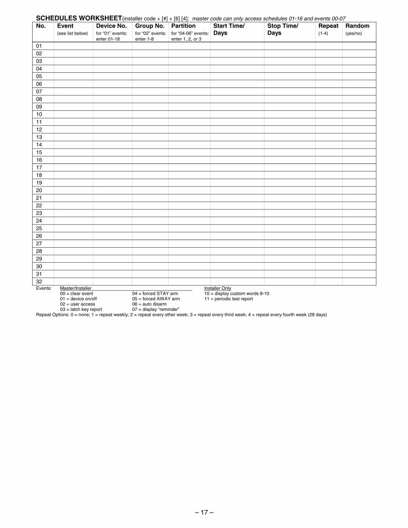
SCHEDULES WORKSHEET(installer code + [#] + [6] [4]; master code can only access schedules 01-16 and events 00-07 No. Event Device No. Group No. Partition Start Time/ Stop Time/ Repeat Random (see list below) for “01” events: for “02” events: for “04-06” events: Days Days (1-4) (yes/no) enter 01-18 enter 1-8 enter 1, 2, or 3
01 02 03 04 05 06 07 08 09 10 11 12 13 14 15 16 17 18 19 20 21 22 23 24 25 26 27 28 29 30 31 32 Events: Master/Installer Installer Only 00 = clear event 04 = forced STAY arm 10 = display custom words 8-10 01 = device on/off 05 = forced AWAY arm 11 = periodic test report 02 = user access 06 = auto disarm 03 = latch key report 07 = display “reminder” Repeat Options: 0 = none; 1 = repeat weekly; 2 = repeat every other week; 3 = repeat every third week; 4 = repeat every fourth week (28 days)
– 17 –
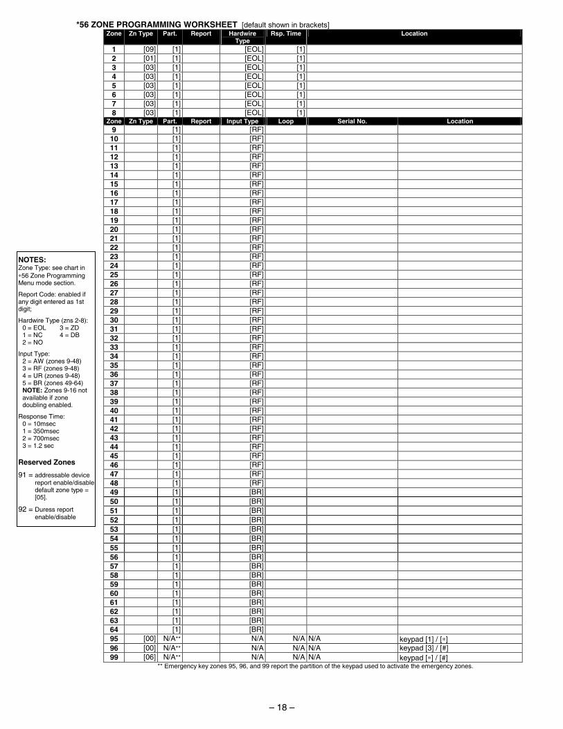
*56 ZONE PROGRAMMING WORKSHEET [default shown in brackets] Zone Zn Type Part. Report Hardwire
Type Rsp. Time Location
1 [09] [1] [EOL] [1] 2 [01] [1] [EOL] [1] 3 [03] [1] [EOL] [1] 4 [03] [1] [EOL] [1] 5 [03] [1] [EOL] [1] 6 [03] [1] [EOL] [1] 7 [03] [1] [EOL] [1] 8 [03] [1] [EOL] [1]
Zone Zn Type Part. Report Input Type Loop Serial No. Location 9 [1] [RF] 10 [1] [RF] 11 [1] [RF] 12 [1] [RF] 13 [1] [RF] 14 [1] [RF] 15 [1] [RF] 16 [1] [RF] 17 [1] [RF] 18 [1] [RF] 19 [1] [RF] 20 [1] [RF] 21 [1] [RF] 22 [1] [RF] 23 [1] [RF] 24 [1] [RF] 25 [1] [RF] 26 [1] [RF] 27 [1] [RF] 28 [1] [RF] 29 [1] [RF] 30 [1] [RF] 31 [1] [RF] 32 [1] [RF] 33 [1] [RF] 34 [1] [RF] 35 [1] [RF] 36 [1] [RF] 37 [1] [RF] 38 [1] [RF] 39 [1] [RF] 40 [1] [RF] 41 [1] [RF] 42 [1] [RF] 43 [1] [RF] 44 [1] [RF] 45 [1] [RF] 46 [1] [RF] 47 [1] [RF] 48 [1] [RF] 49 [1] [BR] 50 [1] [BR] 51 [1] [BR] 52 [1] [BR] 53 [1] [BR] 54 [1] [BR] 55 [1] [BR] 56 [1] [BR] 57 [1] [BR] 58 [1] [BR] 59 [1] [BR] 60 [1] [BR] 61 [1] [BR] 62 [1] [BR] 63 [1] [BR] 64 [1] [BR] 95 [00] N/A** N/A N/A N/A keypad [1] / [∗] 96 [00] N/A** N/A N/A N/A keypad [3] / [#] 99 [06] N/A** N/A N/A N/A keypad [∗] / [#]
** Emergency key zones 95, 96, and 99 report the partition of the keypad used to activate the emergency zones.
NOTES: Zone Type: see chart in ∗56 Zone Programming Menu mode section.
Report Code: enabled if any digit entered as 1st digit;
Hardwire Type (zns 2-8): 0 = EOL 3 = ZD 1 = NC 4 = DB 2 = NO
Input Type: 2 = AW (zones 9-48) 3 = RF (zones 9-48) 4 = UR (zones 9-48) 5 = BR (zones 49-64) NOTE: Zones 9-16 not available if zone doubling enabled.
Response Time: 0 = 10msec 1 = 350msec 2 = 700msec 3 = 1.2 sec
Reserved Zones
91 = addressable device report enable/disable
default zone type = [05].
92 = Duress report enable/disable
– 18 –
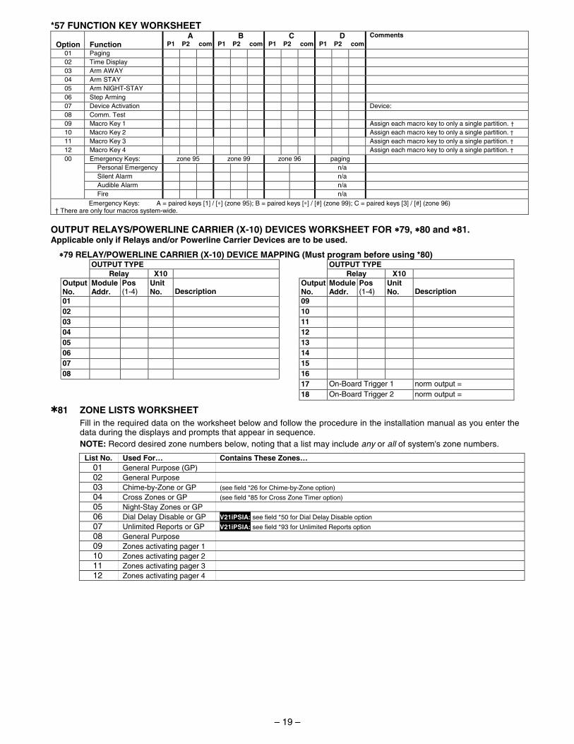
*57 FUNCTION KEY WORKSHEET
Option Function
A P1 P2 com
B P1 P2 com
C P1 P2 com
D P1 P2 com
Comments
01 Paging 02 Time Display 03 Arm AWAY 04 Arm STAY 05 Arm NIGHT-STAY 06 Step Arming 07 Device Activation Device: 08 Comm. Test 09 Macro Key 1 Assign each macro key to only a single partition. † 10 Macro Key 2 Assign each macro key to only a single partition. † 11 Macro Key 3 Assign each macro key to only a single partition. † 12 Macro Key 4 Assign each macro key to only a single partition. † 00 Emergency Keys: zone 95 zone 99 zone 96 paging Personal Emergency n/a Silent Alarm n/a Audible Alarm n/a Fire n/a
Emergency Keys: A = paired keys [1] / [∗] (zone 95); B = paired keys [∗] / [#] (zone 99); C = paired keys [3] / [#] (zone 96) † There are only four macros system-wide.
OUTPUT RELAYS/POWERLINE CARRIER (X-10) DEVICES WORKSHEET FOR ∗∗∗∗79, ∗∗∗∗80 and ∗∗∗∗81. Applicable only if Relays and/or Powerline Carrier Devices are to be used.
∗∗∗∗79 RELAY/POWERLINE CARRIER (X-10) DEVICE MAPPING (Must program before using *80) OUTPUT TYPE OUTPUT TYPE Relay X10 Relay X10 Output No.
Module Addr.
Pos (1-4)
Unit No.
Description
OutputNo.
ModuleAddr.
Pos (1-4)
Unit No.
Description
01 09 02 10 03 11 04 12 05 13 06 14 07 15 08 16 17 On-Board Trigger 1 norm output = 18 On-Board Trigger 2 norm output =
✱81 ZONE LISTS WORKSHEET Fill in the required data on the worksheet below and follow the procedure in the installation manual as you enter the data during the displays and prompts that appear in sequence. NOTE: Record desired zone numbers below, noting that a list may include any or all of system's zone numbers.
List No. Used For… Contains These Zones… 01 General Purpose (GP) 02 General Purpose 03 Chime-by-Zone or GP (see field *26 for Chime-by-Zone option) 04 Cross Zones or GP (see field *85 for Cross Zone Timer option) 05 Night-Stay Zones or GP 06 Dial Delay Disable or GP V21iPSIA: see field *50 for Dial Delay Disable option 07 Unlimited Reports or GP V21iPSIA: see field *93 for Unlimited Reports option 08 General Purpose 09 Zones activating pager 1 10 Zones activating pager 2 11 Zones activating pager 3 12 Zones activating pager 4
– 19 –
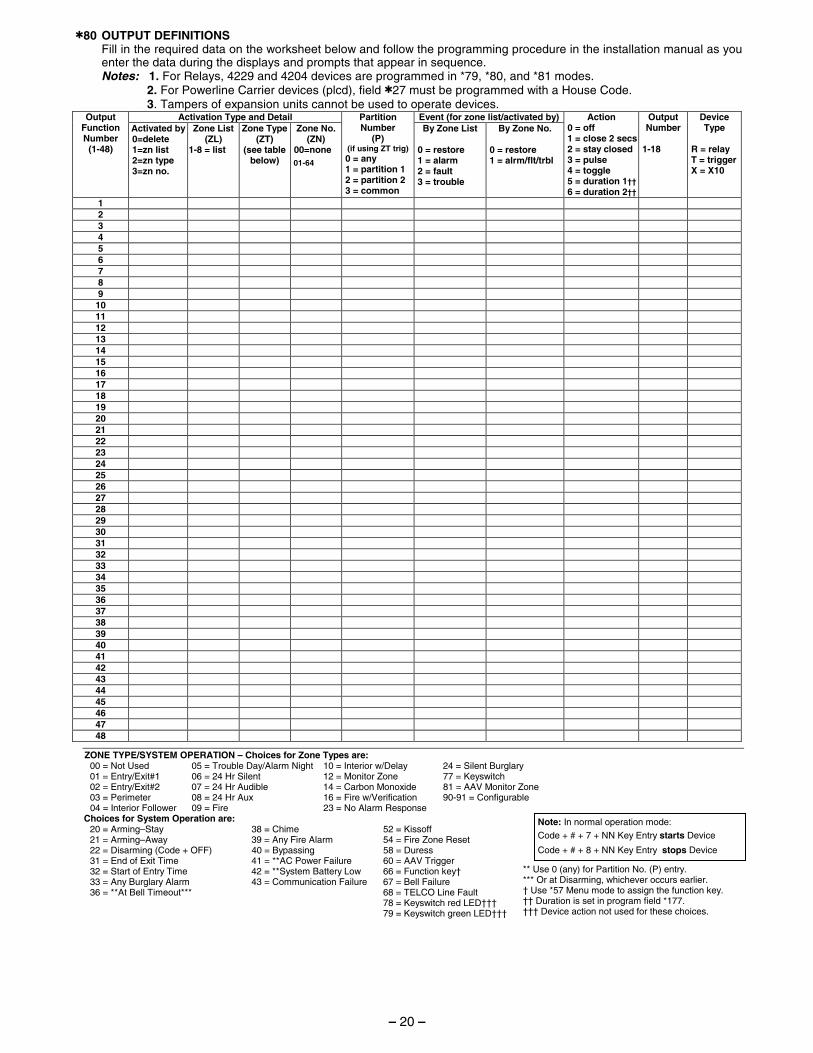
✱80 OUTPUT DEFINITIONS Fill in the required data on the worksheet below and follow the programming procedure in the installation manual as you
enter the data during the displays and prompts that appear in sequence. Notes: 1. For Relays, 4229 and 4204 devices are programmed in *79, *80, and *81 modes. 2. For Powerline Carrier devices (plcd), field ✱27 must be programmed with a House Code. 3. Tampers of expansion units cannot be used to operate devices.
Activation Type and Detail Event (for zone list/activated by)Output Function Number
(1-48)
Activated by 0=delete 1=zn list 2=zn type 3=zn no.
Zone List (ZL)
1-8 = list
Zone Type (ZT)
(see table below)
Zone No. (ZN)
00=none
01-64
Partition Number
(P) (if using ZT trig)
0 = any 1 = partition 1 2 = partition 2 3 = common
By Zone List 0 = restore 1 = alarm 2 = fault 3 = trouble
By Zone No. 0 = restore 1 = alrm/flt/trbl
Action 0 = off 1 = close 2 secs 2 = stay closed 3 = pulse 4 = toggle 5 = duration 1†† 6 = duration 2††
Output Number
1-18
Device Type
R = relay T = trigger X = X10
1 2 3 4 5 6 7 8 9 10 11 12 13 14 15 16 17 18 19 20 21 22 23 24 25 26 27 28 29 30 31 32 33 34 35 36 37 38 39 40 41 42 43 44 45 46 47 48
ZONE TYPE/SYSTEM OPERATION – Choices for Zone Types are: 00 = Not Used 05 = Trouble Day/Alarm Night 10 = Interior w/Delay 24 = Silent Burglary 01 = Entry/Exit#1 06 = 24 Hr Silent 12 = Monitor Zone 77 = Keyswitch 02 = Entry/Exit#2 07 = 24 Hr Audible 14 = Carbon Monoxide 81 = AAV Monitor Zone 03 = Perimeter 08 = 24 Hr Aux 16 = Fire w/Verification 90-91 = Configurable 04 = Interior Follower 09 = Fire 23 = No Alarm Response
Choices for System Operation are: 20 = Arming–Stay 38 = Chime 52 = Kissoff 21 = Arming–Away 39 = Any Fire Alarm 54 = Fire Zone Reset 22 = Disarming (Code + OFF) 40 = Bypassing 58 = Duress 31 = End of Exit Time 41 = **AC Power Failure 60 = AAV Trigger 32 = Start of Entry Time 42 = **System Battery Low 66 = Function key† 33 = Any Burglary Alarm 43 = Communication Failure 67 = Bell Failure 36 = **At Bell Timeout*** 68 = TELCO Line Fault 78 = Keyswitch red LED††† 79 = Keyswitch green LED†††
Note: In normal operation mode:
Code + # + 7 + NN Key Entry starts Device
Code + # + 8 + NN Key Entry stops Device
** Use 0 (any) for Partition No. (P) entry. *** Or at Disarming, whichever occurs earlier. † Use *57 Menu mode to assign the function key. †† Duration is set in program field *177. ††† Device action not used for these choices.
– 20 –
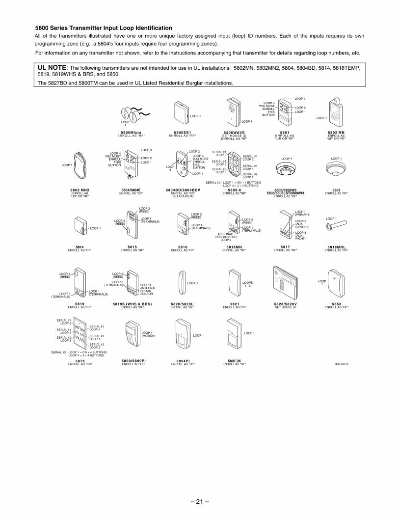
5800 Series Transmitter Input Loop Identification All of the transmitters illustrated have one or more unique factory assigned input (loop) ID numbers. Each of the inputs requires its own
programming zone (e.g., a 5804's four inputs require four programming zones).
For information on any transmitter not shown, refer to the instructions accompanying that transmitter for details regarding loop numbers, etc.
UL NOTE: The following transmitters are not intended for use in UL installations: 5802MN, 5802MN2, 5804, 5804BD, 5814, 5816TEMP, 5819, 5819WHS & BRS, and 5850.
The 5827BD and 5800TM can be used in UL Listed Residential Burglar installations.
LOOP 1
5806/5806W35808/5808LST/5808W3
ENROLL AS "RF"
LOOP 1
5809ENROLL AS "RF"
5818MNLENROLL AS "RF"
LOOP 1
LOOP 1
5814ENROLL AS "RF"
5800-003-V0
LOOP 1(MOTION)
5897-35ENROLL AS "RF"
5890/5890PIENROLL AS "RF"
LOOP 1
5802 MNENROLL AS
"UR" OR "RF"
5805-6ENROLL AS "BR"
5804BD/5804BDVENROLL AS "BR"SET HOUSE ID
LOOP 4YOU MUSTENROLLTHISBUTTONLOOP
3LOOP 1
LOOP 2
•••••
•
••••
•
••••
•
•••
5804/5804EENROLL AS "BR"
5817ENROLL AS "RF"
LOOP 2(AUX.CENTER)
LOOP 1(PRIMARY)
LOOP 3(AUX.RIGHT)
5816ENROLL AS "RF"
LOOP 1(TERMINALS)
LOOP 1(TERMINALS)
LOOP 2(REED)
5816MNENROLL AS "RF"
LOOP 1(TERMINALS)
ALTERNATEPOSITION FOR
LOOP 2
LOOP 2(REED)
LOOP 3(TERMINALS)
5828/5828VSET HOUSE ID
5815ENROLL AS "RF"
5820/5820LENROLL AS "RF"
5819S (WHS & BRS)ENROLL AS "RF"
LOOP 1(INTERNALSHOCKSENSOR
LOOP 2(REED)
5819ENROLL AS "RF"
LOOP 2(REED)
LOOP 3(TERMINALS)
LOOP 1(TERMINALS)
5800WAVESET HOUSE ID
ENROLL AS"RF"
5800MicraENROLL AS "RF"
5800COENROLL AS "RF"
5801ENROLL AS"UR OR"RF"
5800SS1ENROLL AS "RF"
LOOP 3
LOOP 1LOOP 2
LOOP 4YOU MUST
ENROLLTHIS
BUTTON
5894PIENROLL AS "RF"
5802 MN2ENROLL AS
"UR" OR "RF"
LOOP 1
LOOP 1
LOOPS1 - 3
LOOP 1
LOOP 1LOOP 1
LOOP1
LOOP 1
LOOP1
LOOP1
5878ENROLL AS "BR"
5853ENROLL AS "RF"
ARMED
READY
MESSAGE
MIC
43
21
OFF
ON
5821ENROLL AS "RF"
LOOP 4YOU MUST
ENROLLTHIS
BUTTONLOOP 1
LOOP 2
LOOP 3
SERIAL #1LOOP 3
SERIAL #1LOOP 4
SERIAL #2LOOP 3
SERIAL #1LOOP 2
SERIAL #1LOOP 1
SERIAL #2LOOP 2
SERIAL #1LOOP 3
SERIAL #1LOOP 4
SERIAL #2LOOP 3
SERIAL #1LOOP 2
SERIAL #1LOOP 1
SERIAL #2LOOP 2
3
AWAY
STAY
1
2
4
OFF
ON
LOOP 2(REED)
LOOP 2(REED)
SERIAL #2 - LOOP 1 = ON + 4 BUTTONSLOOP 4 = 3 + 4 BUTTONS
SERIAL #2 - LOOP 1 = ON + 4 BUTTONSLOOP 4 = 3 + 4 BUTTONS
– 21 –
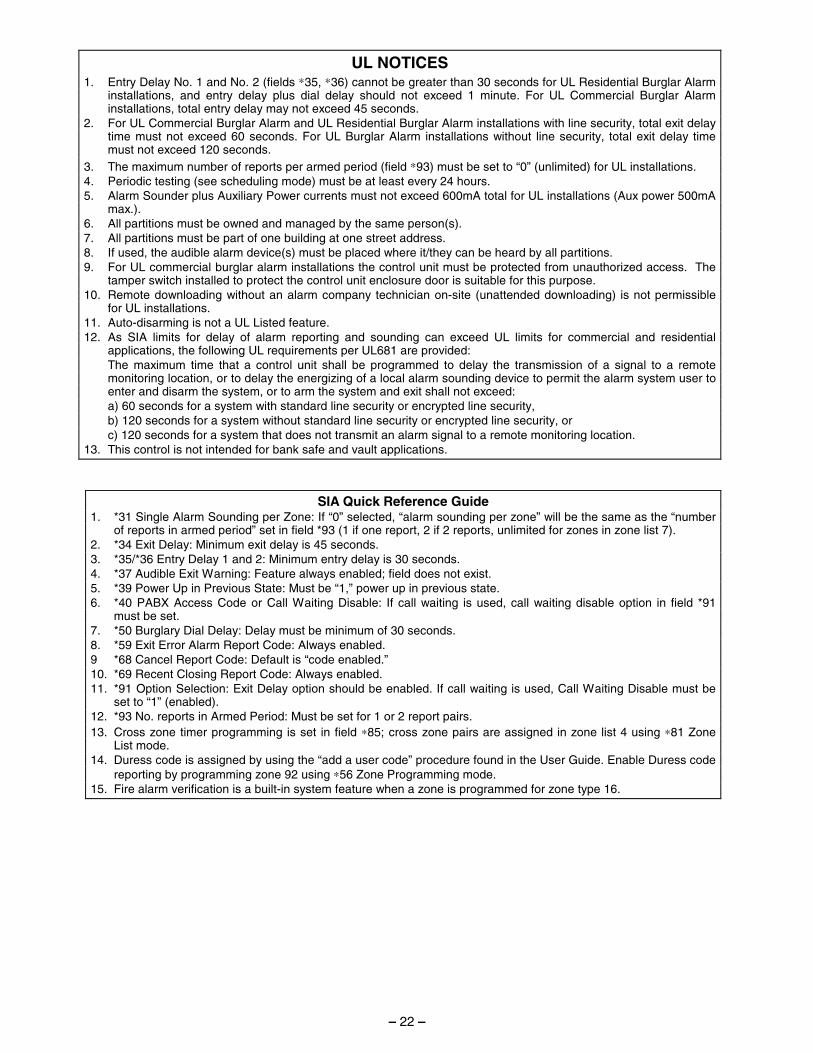
UL NOTICES
1. Entry Delay No. 1 and No. 2 (fields ∗35, ∗36) cannot be greater than 30 seconds for UL Residential Burglar Alarm installations, and entry delay plus dial delay should not exceed 1 minute. For UL Commercial Burglar Alarm installations, total entry delay may not exceed 45 seconds.
2. For UL Commercial Burglar Alarm and UL Residential Burglar Alarm installations with line security, total exit delay time must not exceed 60 seconds. For UL Burglar Alarm installations without line security, total exit delay time must not exceed 120 seconds.
3. The maximum number of reports per armed period (field ∗93) must be set to “0” (unlimited) for UL installations. 4. Periodic testing (see scheduling mode) must be at least every 24 hours. 5. Alarm Sounder plus Auxiliary Power currents must not exceed 600mA total for UL installations (Aux power 500mA
max.). 6. All partitions must be owned and managed by the same person(s). 7. All partitions must be part of one building at one street address. 8. If used, the audible alarm device(s) must be placed where it/they can be heard by all partitions. 9. For UL commercial burglar alarm installations the control unit must be protected from unauthorized access. The
tamper switch installed to protect the control unit enclosure door is suitable for this purpose. 10. Remote downloading without an alarm company technician on-site (unattended downloading) is not permissible
for UL installations. 11. Auto-disarming is not a UL Listed feature. 12. As SIA limits for delay of alarm reporting and sounding can exceed UL limits for commercial and residential
applications, the following UL requirements per UL681 are provided: The maximum time that a control unit shall be programmed to delay the transmission of a signal to a remote
monitoring location, or to delay the energizing of a local alarm sounding device to permit the alarm system user to enter and disarm the system, or to arm the system and exit shall not exceed:
a) 60 seconds for a system with standard line security or encrypted line security, b) 120 seconds for a system without standard line security or encrypted line security, or c) 120 seconds for a system that does not transmit an alarm signal to a remote monitoring location. 13. This control is not intended for bank safe and vault applications.
SIA Quick Reference Guide 1. *31 Single Alarm Sounding per Zone: If “0” selected, “alarm sounding per zone” will be the same as the “number
of reports in armed period” set in field *93 (1 if one report, 2 if 2 reports, unlimited for zones in zone list 7). 2. *34 Exit Delay: Minimum exit delay is 45 seconds. 3. *35/*36 Entry Delay 1 and 2: Minimum entry delay is 30 seconds. 4. *37 Audible Exit Warning: Feature always enabled; field does not exist. 5. *39 Power Up in Previous State: Must be “1,” power up in previous state. 6. *40 PABX Access Code or Call Waiting Disable: If call waiting is used, call waiting disable option in field *91
must be set. 7. *50 Burglary Dial Delay: Delay must be minimum of 30 seconds. 8. *59 Exit Error Alarm Report Code: Always enabled. 9 *68 Cancel Report Code: Default is “code enabled.” 10. *69 Recent Closing Report Code: Always enabled. 11. *91 Option Selection: Exit Delay option should be enabled. If call waiting is used, Call Waiting Disable must be
set to “1” (enabled). 12. *93 No. reports in Armed Period: Must be set for 1 or 2 report pairs. 13. Cross zone timer programming is set in field ∗85; cross zone pairs are assigned in zone list 4 using ∗81 Zone
List mode. 14. Duress code is assigned by using the “add a user code” procedure found in the User Guide. Enable Duress code
reporting by programming zone 92 using ∗56 Zone Programming mode. 15. Fire alarm verification is a built-in system feature when a zone is programmed for zone type 16.
– 22 –

– NOTES –
– 23 –
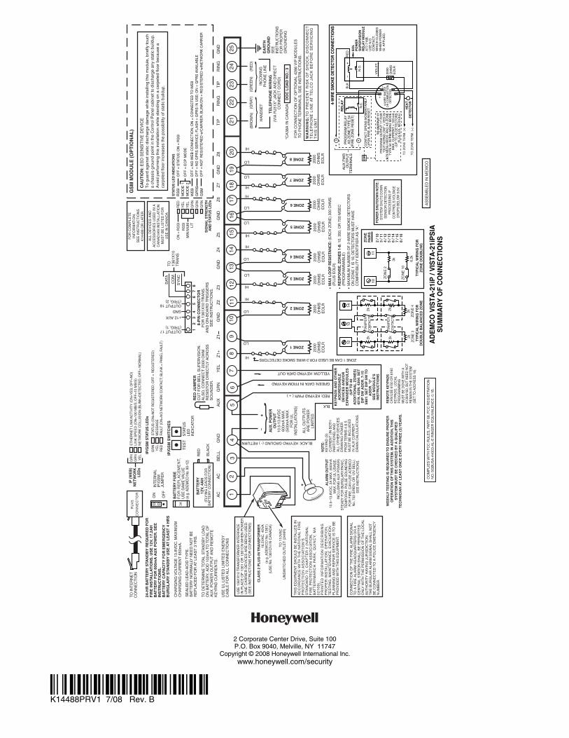
CL
AS
S 2
PL
UG
-IN
TR
AN
SF
OR
ME
R16
.5V
AC
, 40V
A(e
.g. A
DE
MC
O N
o. 1
361)
(US
E N
o. 1
361C
N IN
CA
NA
DA
)
�
+
TH
IS E
QU
IPM
EN
T S
HO
ULD
BE
INS
TALL
ED
IN
AC
CO
RD
AN
CE
WIT
H T
HE
NA
TIO
NA
L F
IRE
PR
OT
EC
TIO
N A
SS
OC
IAT
ION
'S
STA
ND
AR
D 7
2,
CH
AP
TE
R 2
(N
AT
ION
AL
F
IRE
PR
OT
EC
TIO
N A
SS
OC
IAT
ION
,B
AT
TE
RY
MA
RC
H P
AR
K,
QU
INC
Y,
MA
02
16
9).
PR
INT
ED
IN
FO
RM
AT
ION
DE
SC
RIB
ING
PR
OP
ER
IN
STA
LL
AT
ION
, O
PE
RA
TIO
N,
TE
ST
ING
, M
AIN
TE
NA
NC
E,
EV
AC
UAT
ION
PL
AN
NIN
G A
ND
RE
PAIR
SE
RV
ICE
IS
TO
BE
PR
OV
IDE
D W
ITH
TH
IS E
QU
IPM
EN
T.
24-H
R B
AT
TE
RY
STA
ND
BY
RE
QU
IRE
D F
OR
FIR
E IN
STA
LL
AT
ION
S. U
SE
12V
, 17.
2AH
BA
TT
ER
Y F
OR
600
mA
AU
X P
OW
ER
. SE
EIN
ST
RU
CT
ION
S.
BA
TT
ER
Y C
APA
CIT
Y F
OR
EM
ER
GE
NC
YB
UR
GL
AR
Y S
TAN
DB
Y U
SE
AT
LE
AS
T 4
HR
S
US
E U
L LI
ST
ED
LIM
ITE
D E
NE
RG
YC
AB
LE F
OR
ALL
CO
NN
EC
TIO
NS
FO
R C
OM
PLE
TE
INF
OR
MAT
ION
,S
EE
INS
TR
UC
TIO
NS
K14
488
OR
LAT
ER
.
ALA
RM
OU
TPU
T10
.5–1
3.8V
DC
, 2A
MA
X. (
600m
AM
AX
. FO
R U
L U
SA
GE
,IN
CLU
DIN
G A
UX
PO
WE
R)
ST
EA
DY
FO
R B
UR
GLA
RY
/PA
NIC
,T
EM
PO
RA
L P
ULS
E S
OU
ND
ING
FO
R F
IRE
. CA
N U
SE
AD
EM
CO
No.
702
SIR
EN
, OR
12V
BE
LL).
SE
E IN
ST
RU
CT
ION
S.
TO IN
TE
RN
ET
CO
NN
EC
TIO
N
CH
AR
GIN
G V
OLT
AG
E 1
3.8V
DC
. MA
XIM
UM
CH
AR
GIN
G C
UR
RE
NT
650
mA
.
SE
ALE
D L
EA
D-A
CID
TY
PE
.B
ATT
ER
Y N
OR
MA
LLY
NE
ED
NO
T B
ER
EP
LAC
ED
FO
R A
T L
EA
ST
3 Y
RS
.
TO D
ET
ER
MIN
E T
OTA
L S
TAN
DB
Y L
OA
DO
N B
ATT
ER
Y, A
DD
100
mA
TO
TO
TAL
OF
AU
X. P
OW
ER
OU
TP
UT
AN
D R
EM
OT
EK
EY
PAD
CU
RR
EN
TS
.
BA
TT
ER
Y12
V, 4
AH
IP/G
SM
SW
ITC
HE
S
TE
ST
STA
TU
SLE
DIN
DIC
ATO
R
CO
NN
EC
TIO
N O
F T
HE
FIR
E A
LAR
M S
IGN
AL
TO A
FIR
E A
LAR
M H
EA
DQ
UA
RT
ER
S O
R A
CE
NT
RA
L S
TAT
ION
SH
ALL
BE
PE
RM
ITT
ED
ON
LY W
ITH
TH
E P
ER
MIS
SIO
N O
F T
HE
LO
CA
LA
UT
HO
RIT
Y H
AV
ING
JU
RIS
DIC
TIO
N.
TH
E B
UR
GLA
R A
LAR
M S
IGN
AL
SH
ALL
NO
TB
E C
ON
NE
CT
ED
TO
A P
OLI
CE
EM
ER
GE
NC
YN
UM
BE
R.
GN
DZ
5Z
4G
ND
Z3
Z2
GN
DZ
1+Y
EL
GR
NA
UX
AC
AC
BE
LLG
ND
GN
DR
ING
TIP
RIN
GT
IPZ
8G
ND
Z6
Z7
12
37
811
1217
2021
2223
2425 EA
RT
H
GR
OU
ND
SE
E
INS
TR
UC
TIO
NS
FO
R P
RO
PE
RG
RO
UN
DIN
G
TE
LE
PH
ON
E W
IRIN
G(V
IA R
J31X
* JA
CK
AN
D D
IRE
CT
C
ON
NE
CT
CO
RD
)
BLACK: KEYPAD GROUND (- ) RETURN
RED: KEYPAD PWR ( + )
GREEN: DATA IN FROM KEYPAD
YELLOW: KEYPAD DATA OUT
KE
YPA
DS
AN
D O
TH
ER
AD
DR
ES
SA
BL
ED
EV
ICE
S A
ND
/OR
EX
PAN
DE
R M
OD
UL
ES
(UP
TO
40
AD
DIT
ION
AL
ZO
NE
S)
4219
, 422
9, 4
204:
SE
TD
IP S
W A
DD
R. 7
-15
5881
: SE
T D
IP S
W T
OA
DD
R. "
0".
SE
E M
OD
UL
E'S
INS
TR
UC
TIO
NS
(GR
AY)
(GR
EE
N)
(RE
D)
INC
OM
ING
PH
ON
E L
INE
HA
ND
SE
T
ZONE 1
ZONE 2
HI
LO
HI
LO
ZONE 3
ZONE 4
HI
LO
HI
LO
ZONE 5
ZONE 6
HI
LO
HI
LO
ZONE 7
ZONE 8
HI
LO
HI
LO
•
MA
X L
OO
P R
ES
ISTA
NC
E: (
EA
CH
ZO
NE
) 30
0 O
HM
S(P
LUS
EO
LR)
• • R
ES
PO
NS
E, Z
ON
ES
1-8
: 10,
350
, OR
700
MS
EC
(PR
OG
RA
MM
AB
LE)
8-P
IN C
ON
NE
CTO
RF
OR
136
1X10
TR
AN
S.
AN
D O
N-B
OA
RD
TR
IGG
ER
SS
EE
INS
TR
UC
TIO
NS
.
78
(BR
OW
N)
}}
ZONE 1 CAN BE USED FOR 2-WIRE SMOKE DETECTORS
RE
D J
UM
PE
RC
UT
FO
R B
ELL
SU
PE
RV
ISIO
N.
ALS
O, C
ON
NE
CT
200
0 O
HM
RE
SIS
TOR
DIR
EC
TLY
AC
RO
SS
SO
UN
DE
R.
NO
TE:
KE
YPA
D (
S)
CU
RR
EN
T (
IN B
OT
HPA
RT
ITIO
NS
) A
ND
ALL
OT
HE
R D
EV
ICE
SD
RA
WIN
G P
OW
ER
FR
OM
TE
RM
S 4
& 5
MU
ST
BE
INC
LUD
ED
IN A
UX
CU
RR
EN
TD
RA
IN C
ALC
ULA
TIO
NS
.
AU
X. P
OW
ER
OU
TPU
T10
.5-1
3.8V
DC
600m
A M
AX
.(5
00m
A M
AX
.F
OR
UL
INS
TALL
ATIO
NS
)
ALL
OU
TP
UT
SA
RE
PO
WE
RLI
MIT
ED
.
�+}
2000
O
HM
SE
OLR
2000
O
HM
SE
OLR
2000
O
HM
SE
OLR
2000
O
HM
SE
OLR
2000
O
HM
SE
OLR
2000
O
HM
SE
OLR
2000
O
HM
SE
OLR
2000
O
HM
SE
OLR
SY
NC
CO
M
DAT
A
GND
+12 AUX
1819
1615
1413
109
64
12
34
56
OUTPUT 18(TRIG. 2)
OUTPUT 17(TRIG. 1)
MA
XIM
UM
NU
MB
ER
OF
2-W
IRE
SM
OK
E D
ET
EC
TOR
SO
N Z
ON
E 1
IS 1
6; D
ET
EC
TOR
S M
US
T H
AVE
CO
MPA
TIB
ILIT
Y ID
EN
TIF
IER
AS
"A
".
ZON
EPA
IRS
2 / 1
03
/ 11
4 / 1
25
/ 13
6 / 1
47
/ 15
8 / 1
6
AD
EM
CO
VIS
TA-2
1iP
/ V
ISTA
-21i
PS
IAS
UM
MA
RY
OF
CO
NN
EC
TIO
NS
1312
14
1011
6.2k
ZON
E 1
0
3k
ZON
E 2
2k 2k 2kZO
NE
3
2k 2k 2kZO
NE
4
TAM
PE
RC
ON
TAC
TS
TAM
PE
RC
ON
TAC
TS
TYP
ICA
L W
IRIN
G F
OR
ZON
E D
OU
BLI
NG
TYP
ICA
L W
IRIN
G F
OR
DO
UB
LE B
ALA
NC
ED
ZO
NE
RE
MO
TE K
EY
PAD
SC
AN
US
E 6
150
OR
616
0K
EY
PAD
S.
LOC
AL
PR
OG
RA
MM
ING
MU
ST
BE
DO
NE
WIT
H A
6139
/616
0, B
UT
NE
ED
NO
TR
EM
AIN
IN T
HE
SY
STE
M(S
ET
TO A
DD
RE
SS
16)
.
5 BLK
DO
C L
OA
D N
O.:
3
WA
RN
ING
:TO
PR
EV
EN
T R
ISK
OF
SH
OC
K,
DIS
CO
NN
EC
TT
EL
EP
HO
NE
LIN
E A
T T
EL
CO
JA
CK
BE
FO
RE
SE
RV
ICIN
GT
HIS
UN
IT.
FO
R C
ON
NE
CT
ION
OF
OP
TIO
NA
L 42
86 V
IP M
OD
ULE
STO
PH
ON
E T
ER
MIN
ALS
, SE
E IN
ST
RU
CT
ION
S.
CO
MP
LIE
S W
ITH
FC
C R
ULE
S, P
AR
T 6
8. F
CC
RE
GIS
TR
ATIO
NN
O. 5
GB
US
A-4
4003
-AL-
E R
ING
ER
EQ
UIV
ALE
NC
E: 0
.1B
.
ALL
DE
VIC
ES
AN
DA
CC
ES
SO
RIE
S U
SE
D IN
AC
AN
AD
IAN
INS
TALL
ATIO
NM
US
T B
E L
IST
ED
FO
RU
SE
IN C
AN
AD
A
PO
WE
R S
HU
TDO
WN
NO
TE:
SY
STE
M S
HU
TS D
OW
NS
EN
SO
R D
ETE
CTI
ON
PR
OC
ES
SIN
G IF
CO
NTR
OL'
S V
OLT
AGE
DR
OP
S B
ELO
W 9
.6V.
4-W
IRE
SM
OK
E D
ETE
CTO
R C
ON
NE
CTI
ON
S
+
+
2000
OH
MS
EO
LR
HE
AT
DE
TE
CT
OR
RE
D
EO
LP
OW
ER
SU
PE
RV
ISIO
NR
EL
AY
MO
DU
LE
A77
-716
B.
US
E N
.O.
CO
NT
AC
T,
WH
ICH
CLO
SE
SW
HE
N P
OW
ER
IS A
PP
LIE
D.
VIO
LET
AU
X P
WR
OU
TP
UT
TE
RM
INA
LS
5 4_
_
+B
LK
_
TO
ZO
NE
TE
RM
. ( )
TO
ZO
NE
TE
RM
. ( )
RE
LAY
CO
NT
AC
T O
PE
NS
MO
ME
NT
AR
ILY
UP
ON
FIR
E A
LAR
M R
ES
ET
PR
OG
RA
M R
ELA
YA
S Z
ON
E T
YP
E 5
4(F
IRE
ZO
NE
RE
SE
T)
_
+
4-W
IRE
SM
OK
EO
R C
OM
BU
ST
ION
DE
TE
CT
OR
N.C
.N
.O.
TO
OU
TP
UT
17
PR
OG
RA
M O
UT
PU
T 1
7 F
OR
"OU
T N
OR
M L
OW
" =
YE
S IN
7
9 M
EN
U M
OD
E A
ND
AS
ZO
NE
TY
PE
54
IN
80
ME
NU
MO
DE
MA
X. C
UR
RE
NT
= 1
00 m
A(U
P T
O 1
6 D
ET
EC
TO
RS
PLU
S E
OL
MO
DU
LE)
OR
AS
SE
MB
LED
IN M
EX
ICO
WE
EK
LY T
ES
TIN
G IS
RE
QU
IRE
D T
O E
NS
UR
E P
RO
PE
RO
PE
RA
TIO
N O
F T
HIS
SY
ST
EM
. IN
AD
DIT
ION
, TH
ISS
YS
TE
M M
US
T B
E C
HE
CK
ED
BY
A Q
UA
LIF
IED
TE
CH
NIC
IAN
AT
LE
AS
T O
NC
E E
VE
RY
TH
RE
E (
3) Y
EA
RS
.
*CA
38A
IN C
AN
AD
A
BA
TTE
RY
FU
SE
FO
R R
EP
LA
CE
ME
NT,
US
E S
AM
E V
ALU
E(e
.g. A
DE
MC
O N
o. 9
0-12
)
3A
BLA
CK
RE
D
(FLY
ING
LE
AD
S F
OR
BAT
TE
RY
CO
NN
EC
TIO
N)
TO 1361
X10
TR
AN
S
GS
M M
OD
UL
E (
OP
TIO
NA
L)
Z1-
CA
UT
ION
: E
SD
SE
NS
ITIV
E D
EV
ICE
To
guar
d ag
ains
t sta
tic d
isch
arge
dam
age
whi
le in
stal
ling
this
mod
ule,
brie
fly to
uch
a ch
assi
s gr
ound
poi
nt in
the
Con
trol
Pan
el c
abin
et to
dis
char
ge a
ny s
tatic
bui
ldup
.A
void
per
form
ing
this
inst
alla
tion
whi
le s
tand
ing
on a
car
pete
d flo
or b
ecau
se a
carp
eted
floo
r in
crea
ses
the
poss
ibili
ty o
f sta
tic b
uild
up.
RJ4
5C
ON
NE
CT
OR
ET
HE
RN
ET
LIN
K/A
CT
IVIT
Y (
ON
=YE
S; O
FF
=NO
)LI
NK
SP
EE
D (
ON
=100
MB
/S; O
FF
=10
MB
/S)
NE
TW
OR
K C
OLL
ISIO
N (
BLI
NK
=DE
TE
CT
ED
; OF
F=
NO
RM
AL)
GR
NG
RN
YE
L
STA
TU
S (
ON
=NO
T R
EG
IST
ER
ED
; OF
F =
RE
GIS
TE
RE
D)
ME
SS
AG
EFA
ULT
(O
N=N
O N
ET
WO
RK
CO
NTA
CT;
BLI
NK
= P
AN
EL
FAU
LT)
GR
NY
EL
RE
D
IP (W
EB
)N
ETW
OR
KLE
Ds
IP/G
SM
STA
TUS
LE
Ds
RS
SI
MO
DE
1M
OD
E 2
WE
BG
PR
SG
SM
SIG
NA
L S
TRE
NG
THA
ND
STA
TUS
LE
Ds
RE
DY
EL
YE
LG
RN
GR
NG
RN
RS
SI
MIN
IMU
MLI
T
ON
= R
SS
IO
FF
= S
TAT
US
; ON
= R
SS
I
OF
F =
NO
WE
B C
ON
NE
CT
ION
; ON
= C
ON
NE
CT
ED
TO
WE
BO
FF
= N
O G
PR
S S
ER
VIC
E; F
LAS
H =
GP
RS
IN U
SE
; ON
= G
PR
S A
VA
ILA
BLE
OF
F =
NO
T R
EG
IST
ER
ED
w/C
AR
RIE
R; B
LIN
K/O
N =
RE
GIS
TE
RE
D w
/NE
TW
OR
K C
AR
RIE
R
OF
F =
EC
P M
OD
E
STA
TUS
LE
D IN
DIC
ATI
ON
S
TO 1
10V
AC
UN
SW
ITC
HE
D O
UT
LET
(24
HR
)
US
E 1
361X
10 T
RA
NS
FO
RM
ER
INT
ER
FAC
EIN
PLA
CE
OF
136
1 O
R 1
361C
N W
HE
N P
OW
ER
LIN
E C
AR
RIE
R D
EV
ICE
S A
RE
BE
ING
US
ED
.(S
EE
INS
TR
UC
TIO
NS
FO
R C
ON
NE
CT
ION
S)
INT
ER
NA
LIP
/GS
MJU
MP
ER
ON
OF
F
2 Corporate Center Drive, Suite 100 P.O. Box 9040, Melville, NY 11747
Copyright © 2008 Honeywell International Inc. www.honeywell.com/security
ÊK14488PRV14Š K14488PRV1 7/08 Rev. B