Embed Size (px)
Citation preview
VVVVVVVVIIIIIIIISSSSSSSSTTTTTTTTAAAAAAAA--------111111112222222288888888FFFFFFFFBBBBBBBBPPPPPPPP VVVVVVVVIIIIIIIISSSSSSSSTTTTTTTTAAAAAAAA--------222222225555555500000000FFFFFFFFBBBBBBBBPPPPPPPP
Commercial Fire and BurglaryCommercial Fire and BurglaryCommercial Fire and BurglaryCommercial Fire and Burglary Partitioned Security System with SchedulingPartitioned Security System with SchedulingPartitioned Security System with SchedulingPartitioned Security System with Scheduling
Programming Guide
K0376PRV2 7/09 Rev. B
–2–
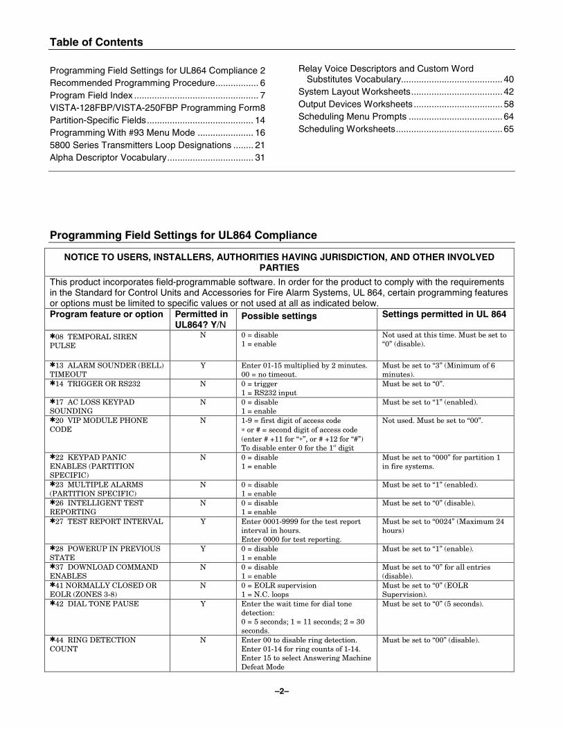
Table of Contents Programming Field Settings for UL864 Compliance 2 Recommended Programming Procedure................. 6 Program Field Index ................................................. 7 VISTA-128FBP/VISTA-250FBP Programming Form8 Partition-Specific Fields.......................................... 14 Programming With #93 Menu Mode ...................... 16 5800 Series Transmitters Loop Designations ........ 21 Alpha Descriptor Vocabulary.................................. 31
Relay Voice Descriptors and Custom Word Substitutes Vocabulary........................................ 40
System Layout Worksheets.................................... 42 Output Devices Worksheets ................................... 58 Scheduling Menu Prompts ..................................... 64 Scheduling Worksheets.......................................... 65
Programming Field Settings for UL864 Compliance
NOTICE TO USERS, INSTALLERS, AUTHORITIES HAVING JURISDICTION, AND OTHER INVOLVED PARTIES
This product incorporates field-programmable software. In order for the product to comply with the requirements in the Standard for Control Units and Accessories for Fire Alarm Systems, UL 864, certain programming features or options must be limited to specific values or not used at all as indicated below. Program feature or option Permitted in
UL864? Y/N Possible settings Settings permitted in UL 864
✱08 TEMPORAL SIREN PULSE
N 0 = disable 1 = enable
Not used at this time. Must be set to “0” (disable).
✱13 ALARM SOUNDER (BELL) TIMEOUT
Y Enter 01-15 multiplied by 2 minutes. 00 = no timeout.
Must be set to “3” (Minimum of 6 minutes).
✱14 TRIGGER OR RS232 N 0 = trigger 1 = RS232 input
Must be set to “0”.
✱17 AC LOSS KEYPAD SOUNDING
N 0 = disable 1 = enable
Must be set to “1” (enabled).
✱20 VIP MODULE PHONE CODE
N 1-9 = first digit of access code ∗ or # = second digit of access code (enter # +11 for “∗”, or # +12 for “#”) To disable enter 0 for the 1st digit
Not used. Must be set to “00”.
✱22 KEYPAD PANIC ENABLES (PARTITION SPECIFIC)
N 0 = disable 1 = enable
Must be set to “000” for partition 1 in fire systems.
✱23 MULTIPLE ALARMS (PARTITION SPECIFIC)
N 0 = disable 1 = enable
Must be set to “1” (enabled).
✱26 INTELLIGENT TEST REPORTING
N 0 = disable 1 = enable
Must be set to “0” (disable).
✱27 TEST REPORT INTERVAL Y Enter 0001-9999 for the test report interval in hours. Enter 0000 for test reporting.
Must be set to “0024” (Maximum 24 hours)
✱28 POWERUP IN PREVIOUS STATE
Y 0 = disable 1 = enable
Must be set to “1” (enable).
✱37 DOWNLOAD COMMAND ENABLES
N 0 = disable 1 = enable
Must be set to “0” for all entries (disable).
✱41 NORMALLY CLOSED OR EOLR (ZONES 3-8)
N 0 = EOLR supervision 1 = N.C. loops
Must be set to “0” (EOLR Supervision).
✱42 DIAL TONE PAUSE Y Enter the wait time for dial tone detection: 0 = 5 seconds; 1 = 11 seconds; 2 = 30 seconds.
Must be set to “0” (5 seconds).
✱44 RING DETECTION COUNT
N Enter 00 to disable ring detection. Enter 01-14 for ring counts of 1-14. Enter 15 to select Answering Machine Defeat Mode
Must be set to “00” (disable).
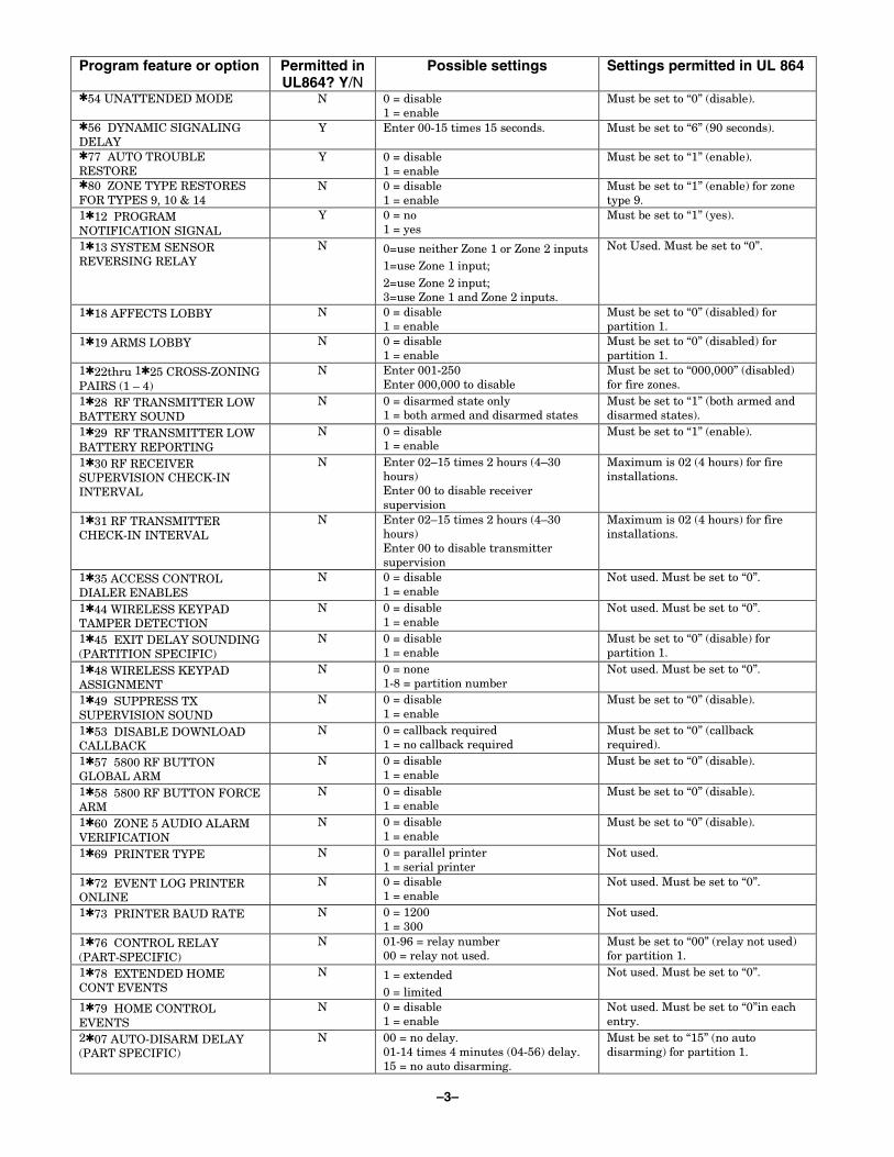
–3–
Program feature or option Permitted in UL864? Y/N
Possible settings Settings permitted in UL 864
✱54 UNATTENDED MODE N 0 = disable 1 = enable
Must be set to “0” (disable).
✱56 DYNAMIC SIGNALING DELAY
Y Enter 00-15 times 15 seconds.
Must be set to “6” (90 seconds).
✱77 AUTO TROUBLE RESTORE
Y 0 = disable 1 = enable
Must be set to “1” (enable).
✱80 ZONE TYPE RESTORES FOR TYPES 9, 10 & 14
N 0 = disable 1 = enable
Must be set to “1” (enable) for zone type 9.
1✱12 PROGRAM NOTIFICATION SIGNAL
Y 0 = no 1 = yes
Must be set to “1” (yes).
1✱13 SYSTEM SENSOR REVERSING RELAY
N 0=use neither Zone 1 or Zone 2 inputs 1=use Zone 1 input; 2=use Zone 2 input; 3=use Zone 1 and Zone 2 inputs.
Not Used. Must be set to “0”.
1✱18 AFFECTS LOBBY N 0 = disable 1 = enable
Must be set to “0” (disabled) for partition 1.
1✱19 ARMS LOBBY N 0 = disable 1 = enable
Must be set to “0” (disabled) for partition 1.
1✱22thru 1✱25 CROSS-ZONING PAIRS (1 – 4)
N Enter 001-250 Enter 000,000 to disable
Must be set to “000,000” (disabled) for fire zones.
1✱28 RF TRANSMITTER LOW BATTERY SOUND
N 0 = disarmed state only 1 = both armed and disarmed states
Must be set to “1” (both armed and disarmed states).
1✱29 RF TRANSMITTER LOW BATTERY REPORTING
N 0 = disable 1 = enable
Must be set to “1” (enable).
1✱30 RF RECEIVER SUPERVISION CHECK-IN INTERVAL
N Enter 02–15 times 2 hours (4–30 hours) Enter 00 to disable receiver supervision
Maximum is 02 (4 hours) for fire installations.
1✱31 RF TRANSMITTER CHECK-IN INTERVAL
N Enter 02–15 times 2 hours (4–30 hours) Enter 00 to disable transmitter supervision
Maximum is 02 (4 hours) for fire installations.
1✱35 ACCESS CONTROL DIALER ENABLES
N 0 = disable 1 = enable
Not used. Must be set to “0”.
1✱44 WIRELESS KEYPAD TAMPER DETECTION
N 0 = disable 1 = enable
Not used. Must be set to “0”.
1✱45 EXIT DELAY SOUNDING (PARTITION SPECIFIC)
N 0 = disable 1 = enable
Must be set to “0” (disable) for partition 1.
1✱48 WIRELESS KEYPAD ASSIGNMENT
N 0 = none 1-8 = partition number
Not used. Must be set to “0”.
1✱49 SUPPRESS TX SUPERVISION SOUND
N 0 = disable 1 = enable
Must be set to “0” (disable).
1✱53 DISABLE DOWNLOAD CALLBACK
N 0 = callback required 1 = no callback required
Must be set to “0” (callback required).
1✱57 5800 RF BUTTON GLOBAL ARM
N 0 = disable 1 = enable
Must be set to “0” (disable).
1✱58 5800 RF BUTTON FORCE ARM
N 0 = disable 1 = enable
Must be set to “0” (disable).
1✱60 ZONE 5 AUDIO ALARM VERIFICATION
N 0 = disable 1 = enable
Must be set to “0” (disable).
1✱69 PRINTER TYPE N 0 = parallel printer 1 = serial printer
Not used.
1✱72 EVENT LOG PRINTER ONLINE
N 0 = disable 1 = enable
Not used. Must be set to “0”.
1✱73 PRINTER BAUD RATE N 0 = 1200 1 = 300
Not used.
1✱76 CONTROL RELAY (PART-SPECIFIC)
N 01-96 = relay number 00 = relay not used.
Must be set to “00” (relay not used) for partition 1.
1✱78 EXTENDED HOME CONT EVENTS
N 1 = extended 0 = limited
Not used. Must be set to “0”.
1✱79 HOME CONTROL EVENTS
N 0 = disable 1 = enable
Not used. Must be set to “0”in each entry.
2✱07 AUTO-DISARM DELAY (PART SPECIFIC)
N 00 = no delay. 01-14 times 4 minutes (04-56) delay. 15 = no auto disarming.
Must be set to “15” (no auto disarming) for partition 1.
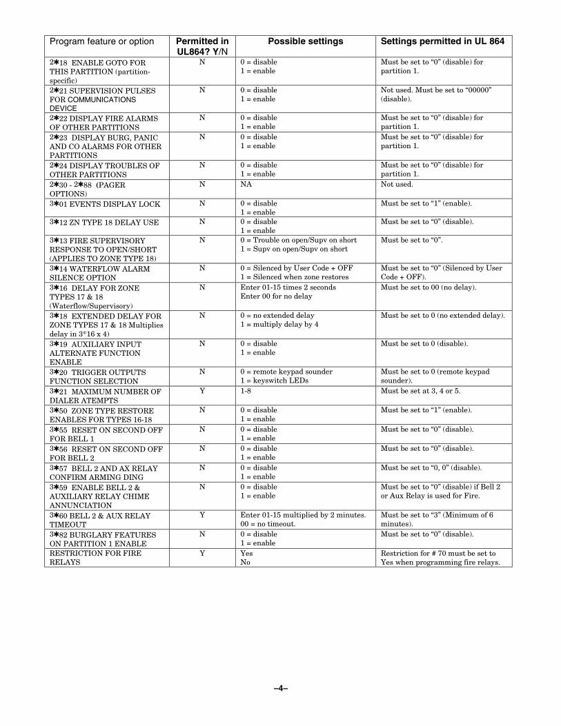
–4–
Program feature or option Permitted in UL864? Y/N
Possible settings Settings permitted in UL 864
2✱18 ENABLE GOTO FOR THIS PARTITION (partition-specific)
N 0 = disable 1 = enable
Must be set to “0” (disable) for partition 1.
2✱21 SUPERVISION PULSES FOR COMMUNICATIONS DEVICE
N 0 = disable 1 = enable
Not used. Must be set to “00000” (disable).
2✱22 DISPLAY FIRE ALARMS OF OTHER PARTITIONS
N 0 = disable 1 = enable
Must be set to “0” (disable) for partition 1.
2✱23 DISPLAY BURG, PANIC AND CO ALARMS FOR OTHER PARTITIONS
N 0 = disable 1 = enable
Must be set to “0” (disable) for partition 1.
2✱24 DISPLAY TROUBLES OF OTHER PARTITIONS
N 0 = disable 1 = enable
Must be set to “0” (disable) for partition 1.
2✱30 - 2✱88 (PAGER OPTIONS)
N NA Not used.
3✱01 EVENTS DISPLAY LOCK N 0 = disable 1 = enable
Must be set to “1” (enable).
3✱12 ZN TYPE 18 DELAY USE N 0 = disable 1 = enable
Must be set to “0” (disable).
3✱13 FIRE SUPERVISORY RESPONSE TO OPEN/SHORT (APPLIES TO ZONE TYPE 18)
N 0 = Trouble on open/Supv on short 1 = Supv on open/Supv on short
Must be set to “0”.
3✱14 WATERFLOW ALARM SILENCE OPTION
N 0 = Silenced by User Code + OFF 1 = Silenced when zone restores
Must be set to “0” (Silenced by User Code + OFF).
3✱16 DELAY FOR ZONE TYPES 17 & 18 (Waterflow/Supervisory)
N Enter 01-15 times 2 seconds Enter 00 for no delay
Must be set to 00 (no delay).
3✱18 EXTENDED DELAY FOR ZONE TYPES 17 & 18 Multiplies delay in 3*16 x 4)
N 0 = no extended delay 1 = multiply delay by 4
Must be set to 0 (no extended delay).
3✱19 AUXILIARY INPUT ALTERNATE FUNCTION ENABLE
N 0 = disable 1 = enable
Must be set to 0 (disable).
3✱20 TRIGGER OUTPUTS FUNCTION SELECTION
N 0 = remote keypad sounder 1 = keyswitch LEDs
Must be set to 0 (remote keypad sounder).
3✱21 MAXIMUM NUMBER OF DIALER ATEMPTS
Y 1-8 Must be set at 3, 4 or 5.
3✱50 ZONE TYPE RESTORE ENABLES FOR TYPES 16-18
N 0 = disable 1 = enable
Must be set to “1” (enable).
3✱55 RESET ON SECOND OFF FOR BELL 1
N 0 = disable 1 = enable
Must be set to “0” (disable).
3✱56 RESET ON SECOND OFF FOR BELL 2
N 0 = disable 1 = enable
Must be set to “0” (disable).
3✱57 BELL 2 AND AX RELAY CONFIRM ARMING DING
N 0 = disable 1 = enable
Must be set to “0, 0” (disable).
3✱59 ENABLE BELL 2 & AUXILIARY RELAY CHIME ANNUNCIATION
N 0 = disable 1 = enable
Must be set to “0” (disable) if Bell 2 or Aux Relay is used for Fire.
3✱60 BELL 2 & AUX RELAY TIMEOUT
Y Enter 01-15 multiplied by 2 minutes. 00 = no timeout.
Must be set to “3” (Minimum of 6 minutes).
3✱82 BURGLARY FEATURES ON PARTITION 1 ENABLE
N 0 = disable 1 = enable
Must be set to “0” (disable).
RESTRICTION FOR FIRE RELAYS
Y Yes No
Restriction for # 70 must be set to Yes when programming fire relays.
–5–
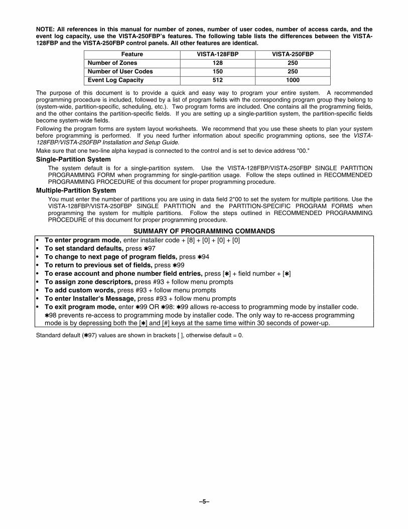
NOTE: All references in this manual for number of zones, number of user codes, number of access cards, and the event log capacity, use the VISTA-250FBP’s features. The following table lists the differences between the VISTA-128FBP and the VISTA-250FBP control panels. All other features are identical.
Feature VISTA-128FBP VISTA-250FBP Number of Zones 128 250 Number of User Codes 150 250 Event Log Capacity 512 1000
The purpose of this document is to provide a quick and easy way to program your entire system. A recommended programming procedure is included, followed by a list of program fields with the corresponding program group they belong to (system-wide, partition-specific, scheduling, etc.). Two program forms are included. One contains all the programming fields, and the other contains the partition-specific fields. If you are setting up a single-partition system, the partition-specific fields become system-wide fields. Following the program forms are system layout worksheets. We recommend that you use these sheets to plan your system before programming is performed. If you need further information about specific programming options, see the VISTA-128FBP/VISTA-250FBP Installation and Setup Guide. Make sure that one two-line alpha keypad is connected to the control and is set to device address "00."
Single-Partition System The system default is for a single-partition system. Use the VISTA-128FBP/VISTA-250FBP SINGLE PARTITION PROGRAMMING FORM when programming for single-partition usage. Follow the steps outlined in RECOMMENDED PROGRAMMING PROCEDURE of this document for proper programming procedure.
Multiple-Partition System You must enter the number of partitions you are using in data field 2*00 to set the system for multiple partitions. Use the VISTA-128FBP/VISTA-250FBP SINGLE PARTITION and the PARTITION-SPECIFIC PROGRAM FORMS when programming the system for multiple partitions. Follow the steps outlined in RECOMMENDED PROGRAMMING PROCEDURE of this document for proper programming procedure.
SUMMARY OF PROGRAMMING COMMANDS • To enter program mode, enter installer code + [8] + [0] + [0] + [0] • To set standard defaults, press ✱97 • To change to next page of program fields, press ✱94 • To return to previous set of fields, press ✱99 • To erase account and phone number field entries, press [✱] + field number + [✱] • To assign zone descriptors, press #93 + follow menu prompts • To add custom words, press #93 + follow menu prompts • To enter Installer's Message, press #93 + follow menu prompts • To exit program mode, enter ✱99 OR ✱98: ✱99 allows re-access to programming mode by installer code. ✱98 prevents re-access to programming mode by installer code. The only way to re-access programming
mode is by depressing both the [✱] and [#] keys at the same time within 30 seconds of power-up.
Standard default (✱97) values are shown in brackets [ ], otherwise default = 0.

–6–
Recommended Programming Procedure
The following is a step-by-step procedure recommended for programming your VISTA-128FBP/VISTA-250FBP system.
1. Set the keypads (and other peripheral devices) to the appropriate addresses.
2. Set factory defaults by pressing ✱97. This will automatically enable keypad addresses 00-01, so be sure at least one keypad is set to one of these addresses.
3. Program system-wide (global) data fields. Using the programming form as a guide, enter program mode and program all system-wide programming fields. These options affect the entire system, regardless of partitions. They include control options, downloader and dialer options, RF options, event logging options, etc. Refer to the Program Field Index for a listing of the program fields and their function. Note that field 2✱00 (number of partitions) must be programmed before continuing.
4. Program partition-specific fields. When the system-wide fields have been programmed, program all partition-specific programming fields by first pressing ✱91 to select a partition (while still in data field program mode). Then enter the first partition-specific field number ✱09. When you are finished, the next partition-specific field is automatically displayed. Partition-specific fields can have different values for each partition. To program the fields for the next partition, press ✱91, enter the desired partition number, then enter field ✱09. Refer to the MECHANICS OF PROGRAMMING section in the VISTA-128FBP/VISTA-250FBP Installation and Setup Guide for detailed instructions.
5. Use #93 Menu Mode for device programming. Refer to Device Programming in this guide to assign keypad ID numbers and default partitions for each keypad, and to selectively suppress certain keypad sounding options. Also use this mode to assign RF receivers, relay modules, and Communicators (7845i-ent).
6. Use #93 Menu Mode for zone programming. Refer to Zone Programming in this guide to program zone response types, assign right loop zones and wireless zones, assign zones to partitions, and to program alarm report codes.
7. Use #93 Menu Mode for programming outputs. Refer to Output Programming in this guide to program desired output operation.
8. Program Communication options. Refer to System Communication section in the VISTA-128FBP/VISTA-250FBP Installation and Setup Guide for detailed instructions. Then use #93 menu mode to program report codes.
9. Use #93 Menu Mode for programming alpha descriptors. Refer to Alpha Programming in this guide to enter zone and partition descriptors and a custom installer's message.
10. Use #80 Mode for programming schedules. Refer to the Scheduling Menu Prompts in the VISTA-128FBP/VISTA-250FBP Installation and Setup Guide to program open/close schedules, temporary and holiday schedules, limitation of access schedules, and time-driven events.
11. Define user access codes. Refer to User Access Codes in the VISTA-128FBP/VISTA-250FBP Installation and Setup Guide to program authority level, O/C reporting option, partition assignments, and wireless key assignments for each user.
12. Exit Programming Mode. Exit programming mode by pressing either ✱98 or ✱99. Additional entries of ✱99 are required if the exit is being done from fields 1✱00 and above.
To prevent re-access to programming mode using the Installer's code, use ✱98. The only way to re-access programming mode is by depressing both the [✱] and [#] keys at the same time within 30 seconds of power-up.
Exiting by using ✱99 always allows reentry into programming mode using the Installer code. Either way of exiting allows access via downloading. Note that if local programming lockout is set via downloading, programming mode cannot be entered at the keypad.
–7–
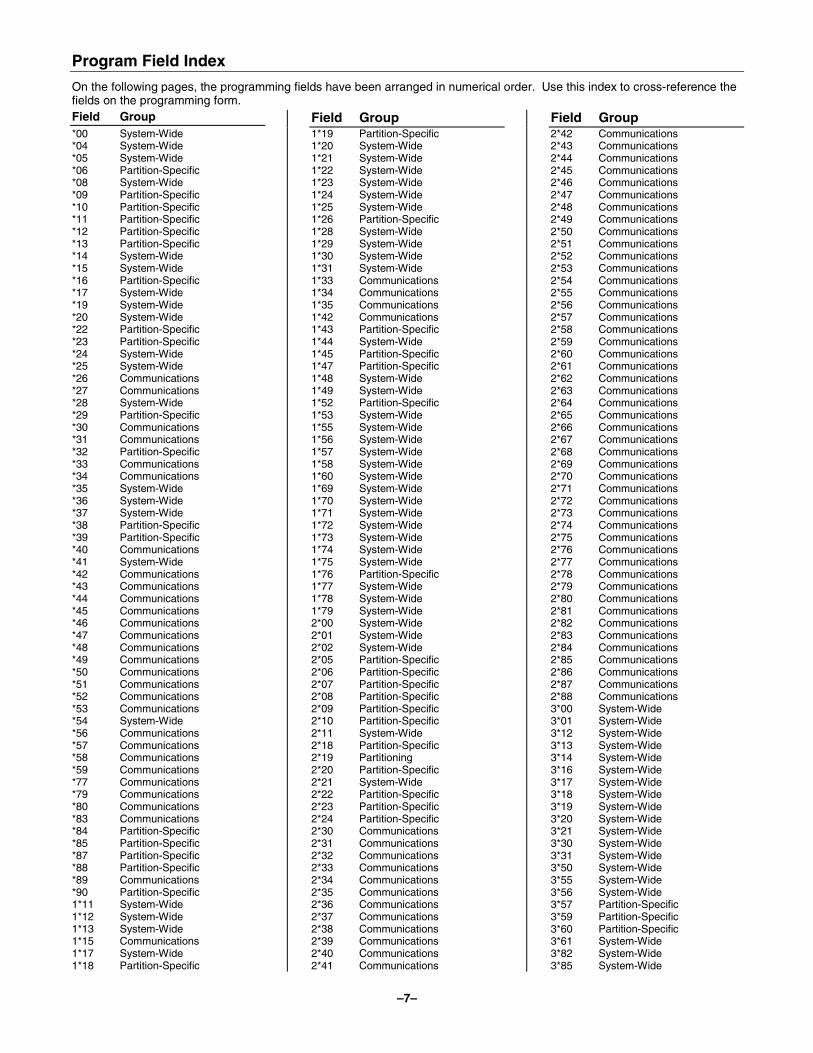
Program Field Index
On the following pages, the programming fields have been arranged in numerical order. Use this index to cross-reference the fields on the programming form. Field Group Field Group Field Group *00 System-Wide *04 System-Wide *05 System-Wide *06 Partition-Specific *08 System-Wide *09 Partition-Specific *10 Partition-Specific *11 Partition-Specific *12 Partition-Specific *13 Partition-Specific *14 System-Wide *15 System-Wide *16 Partition-Specific *17 System-Wide *19 System-Wide *20 System-Wide *22 Partition-Specific *23 Partition-Specific *24 System-Wide *25 System-Wide *26 Communications *27 Communications *28 System-Wide *29 Partition-Specific *30 Communications *31 Communications *32 Partition-Specific *33 Communications *34 Communications *35 System-Wide *36 System-Wide *37 System-Wide *38 Partition-Specific *39 Partition-Specific *40 Communications *41 System-Wide *42 Communications *43 Communications *44 Communications *45 Communications *46 Communications *47 Communications *48 Communications *49 Communications *50 Communications *51 Communications *52 Communications *53 Communications *54 System-Wide *56 Communications *57 Communications *58 Communications *59 Communications *77 Communications *79 Communications *80 Communications *83 Communications *84 Partition-Specific *85 Partition-Specific *87 Partition-Specific *88 Partition-Specific *89 Communications *90 Partition-Specific 1*11 System-Wide 1*12 System-Wide 1*13 System-Wide 1*15 Communications 1*17 System-Wide 1*18 Partition-Specific
1*19 Partition-Specific 1*20 System-Wide 1*21 System-Wide 1*22 System-Wide 1*23 System-Wide 1*24 System-Wide 1*25 System-Wide 1*26 Partition-Specific 1*28 System-Wide 1*29 System-Wide 1*30 System-Wide 1*31 System-Wide 1*33 Communications 1*34 Communications 1*35 Communications 1*42 Communications 1*43 Partition-Specific 1*44 System-Wide 1*45 Partition-Specific 1*47 Partition-Specific 1*48 System-Wide 1*49 System-Wide 1*52 Partition-Specific 1*53 System-Wide 1*55 System-Wide 1*56 System-Wide 1*57 System-Wide 1*58 System-Wide 1*60 System-Wide 1*69 System-Wide 1*70 System-Wide 1*71 System-Wide 1*72 System-Wide 1*73 System-Wide 1*74 System-Wide 1*75 System-Wide 1*76 Partition-Specific 1*77 System-Wide 1*78 System-Wide 1*79 System-Wide 2*00 System-Wide 2*01 System-Wide 2*02 System-Wide 2*05 Partition-Specific 2*06 Partition-Specific 2*07 Partition-Specific 2*08 Partition-Specific 2*09 Partition-Specific 2*10 Partition-Specific 2*11 System-Wide 2*18 Partition-Specific 2*19 Partitioning 2*20 Partition-Specific 2*21 System-Wide 2*22 Partition-Specific 2*23 Partition-Specific 2*24 Partition-Specific 2*30 Communications 2*31 Communications 2*32 Communications 2*33 Communications 2*34 Communications 2*35 Communications 2*36 Communications 2*37 Communications 2*38 Communications 2*39 Communications 2*40 Communications 2*41 Communications
2*42 Communications 2*43 Communications 2*44 Communications 2*45 Communications 2*46 Communications 2*47 Communications 2*48 Communications 2*49 Communications 2*50 Communications 2*51 Communications 2*52 Communications 2*53 Communications 2*54 Communications 2*55 Communications 2*56 Communications 2*57 Communications 2*58 Communications 2*59 Communications 2*60 Communications 2*61 Communications 2*62 Communications 2*63 Communications 2*64 Communications 2*65 Communications 2*66 Communications 2*67 Communications 2*68 Communications 2*69 Communications 2*70 Communications 2*71 Communications 2*72 Communications 2*73 Communications 2*74 Communications 2*75 Communications 2*76 Communications 2*77 Communications 2*78 Communications 2*79 Communications 2*80 Communications 2*81 Communications 2*82 Communications 2*83 Communications 2*84 Communications 2*85 Communications 2*86 Communications 2*87 Communications 2*88 Communications 3*00 System-Wide 3*01 System-Wide 3*12 System-Wide 3*13 System-Wide 3*14 System-Wide 3*16 System-Wide 3*17 System-Wide 3*18 System-Wide 3*19 System-Wide 3*20 System-Wide 3*21 System-Wide 3*30 System-Wide 3*31 System-Wide 3*50 System-Wide 3*55 System-Wide 3*56 System-Wide 3*57 Partition-Specific 3*59 Partition-Specific 3*60 Partition-Specific 3*61 System-Wide 3*82 System-Wide 3*85 System-Wide
– 8 –
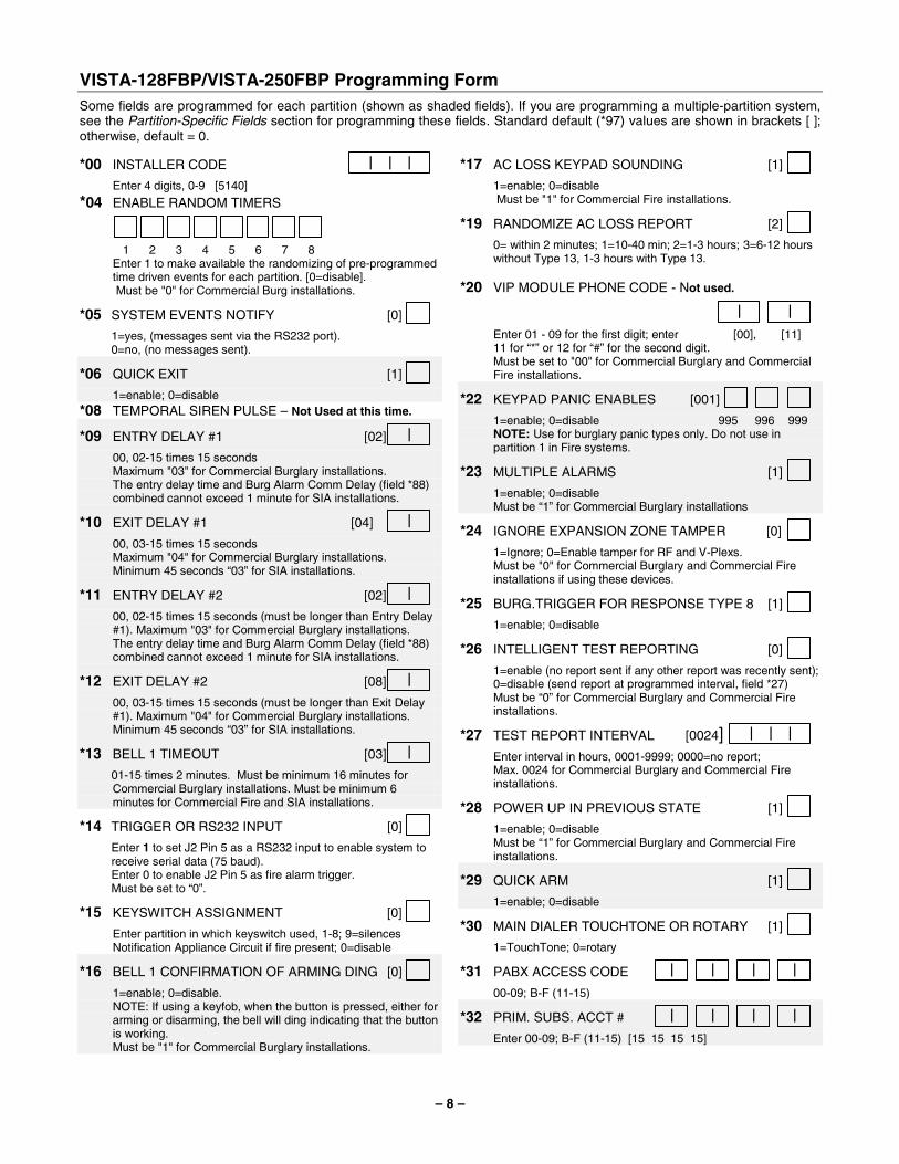
VISTA-128FBP/VISTA-250FBP Programming Form Some fields are programmed for each partition (shown as shaded fields). If you are programming a multiple-partition system, see the Partition-Specific Fields section for programming these fields. Standard default (*97) values are shown in brackets [ ]; otherwise, default = 0.
*00 INSTALLER CODE | | | Enter 4 digits, 0-9 [5140]
*04 ENABLE RANDOM TIMERS
1
2
3
4
5
6
7
8
Enter 1 to make available the randomizing of pre-programmed time driven events for each partition. [0=disable].
Must be "0" for Commercial Burg installations.
*05 SYSTEM EVENTS NOTIFY [0] 1=yes, (messages sent via the RS232 port). 0=no, (no messages sent).
*06 QUICK EXIT [1] 1=enable; 0=disable *08 TEMPORAL SIREN PULSE – Not Used at this time.
*09 ENTRY DELAY #1 [02] | 00, 02-15 times 15 seconds Maximum "03" for Commercial Burglary installations. The entry delay time and Burg Alarm Comm Delay (field *88)
combined cannot exceed 1 minute for SIA installations.
*10 EXIT DELAY #1 [04] | 00, 03-15 times 15 seconds Maximum "04" for Commercial Burglary installations. Minimum 45 seconds “03” for SIA installations.
*11 ENTRY DELAY #2 [02] | 00, 02-15 times 15 seconds (must be longer than Entry Delay
#1). Maximum "03" for Commercial Burglary installations. The entry delay time and Burg Alarm Comm Delay (field *88)
combined cannot exceed 1 minute for SIA installations.
*12 EXIT DELAY #2 [08] | 00, 03-15 times 15 seconds (must be longer than Exit Delay
#1). Maximum "04" for Commercial Burglary installations. Minimum 45 seconds “03” for SIA installations.
*13 BELL 1 TIMEOUT [03] | 01-15 times 2 minutes. Must be minimum 16 minutes for
Commercial Burglary installations. Must be minimum 6 minutes for Commercial Fire and SIA installations.
*14 TRIGGER OR RS232 INPUT [0] Enter 1 to set J2 Pin 5 as a RS232 input to enable system to
receive serial data (75 baud). Enter 0 to enable J2 Pin 5 as fire alarm trigger. Must be set to “0”.
*15 KEYSWITCH ASSIGNMENT [0] Enter partition in which keyswitch used, 1-8; 9=silences
Notification Appliance Circuit if fire present; 0=disable
*16 BELL 1 CONFIRMATION OF ARMING DING [0] 1=enable; 0=disable. NOTE: If using a keyfob, when the button is pressed, either for
arming or disarming, the bell will ding indicating that the button is working.
Must be "1" for Commercial Burglary installations.
*17 AC LOSS KEYPAD SOUNDING [1] 1=enable; 0=disable Must be "1" for Commercial Fire installations.
*19 RANDOMIZE AC LOSS REPORT [2] 0= within 2 minutes; 1=10-40 min; 2=1-3 hours; 3=6-12 hours
without Type 13, 1-3 hours with Type 13. *20 VIP MODULE PHONE CODE - Not used.
| | Enter 01 - 09 for the first digit; enter [00], [11] 11 for “*” or 12 for “#” for the second digit. Must be set to "00" for Commercial Burglary and Commercial
Fire installations.
*22 KEYPAD PANIC ENABLES [001] 1=enable; 0=disable 995 996 999 NOTE: Use for burglary panic types only. Do not use in
partition 1 in Fire systems.
*23 MULTIPLE ALARMS [1] 1=enable; 0=disable Must be “1” for Commercial Burglary installations
*24 IGNORE EXPANSION ZONE TAMPER [0] 1=Ignore; 0=Enable tamper for RF and V-Plexs. Must be "0" for Commercial Burglary and Commercial Fire
installations if using these devices.
*25 BURG.TRIGGER FOR RESPONSE TYPE 8 [1] 1=enable; 0=disable
*26 INTELLIGENT TEST REPORTING [0] 1=enable (no report sent if any other report was recently sent);
0=disable (send report at programmed interval, field *27) Must be “0” for Commercial Burglary and Commercial Fire
installations.
*27 TEST REPORT INTERVAL [0024] | | | Enter interval in hours, 0001-9999; 0000=no report; Max. 0024 for Commercial Burglary and Commercial Fire
installations.
*28 POWER UP IN PREVIOUS STATE [1] 1=enable; 0=disable Must be “1” for Commercial Burglary and Commercial Fire
installations.
*29 QUICK ARM [1] 1=enable; 0=disable
*30 MAIN DIALER TOUCHTONE OR ROTARY [1] 1=TouchTone; 0=rotary
*31 PABX ACCESS CODE | | | | 00-09; B-F (11-15)
*32 PRIM. SUBS. ACCT # | | | | Enter 00-09; B-F (11-15) [15 15 15 15]
– 9 –
*33 PRIMARY PHONE NUMBER
Enter 0-9 for each digit. Enter #11 for *, #12 for #, #13 for 2-second pause *34 SECONDARY PHONE NUMBER
Enter 0-9 for each digit. Enter #11 for *, #12 for #, #13 for 2-second pause *35 DOWNLOAD PHONE NO.
Enter 0-9 for each digit. Enter #11 for *, #12 for #, #13 for 2-second pause *36 DOWNLOAD ID NO.
| | | | | | | |
Enter 00-09; A-F (10-15) [15 15 15 15 15 15 15 15] *37 DOWNLOAD COMMAND ENABLES
Dlr Shtdwn
Sys Shtdwn
0 Not Used
Rmt Byp
Rmt Disarm
Rmt Arm
Upld Pgm
Dwnld Pgm
See field 1*53 for Callback disable option; [1=enable]; 0=disable. For Commercial Burglary and Commercial Fire installations, all entries must be "0."
*38 PREVENT ZONE XXX BYPASS [000] | | 001-250; 000 if all zones can be bypassed
*39 ENABLE OPEN/CLOSE REPORT FOR [1] INSTALLER CODE 1=enable; 0=disable
*40 OPEN/CLOSE REPORT FOR KEYSWITCH [0] 1=enable; 0=disable
*41 NORMALLY CLOSED or EOLR (Zones 3-8) [0] 1=N.C.loops; 0=EOLR supervision. Must be "0" for Commercial Burglary and Commercial Fire
installations.
*42 DIAL TONE PAUSE [0] 0=5 seconds; 1=11 seconds; 2=30 seconds. Must be "0" Commercial Burglary and Commercial Fire
installations.
*43 DIAL TONE DETECTION [1] 1=wait for true dial tone; 0=pause, then dial
*44 RING DETECTION COUNT [00] | 01-14; 15=answering machine; 00=no detection. Must be "00" for Commercial Burglary and Commercial Fire
installations.
*45 PRIMARY FORMAT [1] 0=Low Speed; 1=Contact ID; 2=ADEMCO High Speed; 3= ADEMCO Express
*46 LOW SPEED FORMAT (Primary) [0] 0= ADEMCO Low Speed; 1=Sescoa/Radionics
*47 SECONDARY FORMAT [1] 0=Low Speed; 1=Contact ID; 2= ADEMCO High Speed; 3= ADEMCO Express
*48 LOW SPEED FORMAT (Sec.) [0] 0= ADEMCO Low Speed; 1=Sescoa/Radionics
*49 CHECKSUM VERIFICATION [0] [0] 1=enable; 0=disable Prim Sec
*50 SESCOA/RADIONICS SELECT [0] 1=Sescoa; 0=Radionics
*51 DUAL REPORTING [0] 1=yes; 0=no If used with Spilt Reporting "1" option (1*34),
alarms and alarm restores go to both primary and secondary numbers, while all other reports go to secondary only. If used with Split Reporting "2" option, alarms and alarm restores go to both, open/close and test messages go to secondary only, while all other reports go to primary. If used with Split Reporting “3” option, fire alarms and fire restores signals go to both, all other reports go to secondary only.
*52 STANDARD/EXPANDED REPORT FOR PRIMARY
[0 0 0 0 0 0] Alarm
Rstr
Byp
Trbl
O/C
LoBat
0=standard; 1=expanded; NOTE: Expanded overrides 4+2 format. *53 STANDARD/EXPANDED REPORT FOR SECONDARY
[0 0 0 0 0 0] Alarm
Rstr
Byp
Trbl
O/C
LoBat
0=standard; 1=expanded; NOTE: Expanded overrides 4+2 format.
*54 UNATTENDED MODE [1] 0=disable, 1=enable, if automatic downloads will be allowed Must be "0" for Commercial Fire installations.
*56 DYNAMIC SIGNALING DELAY [03] | Select the delay time (00-15) times 15 seconds before sending
to second destination. NOTE: When Communicator is used as a backup to the dialer,
the Dynamic Signaling Delay (*56) should be set to a minimum of 1 minute.
*57 DYNAMIC SIGNALING PRIORITY [0] 0=Primary dialer; 1=Communicator, as first reporting
destination. *58 COMM CENTRAL STATION #1 CATEGORY ENABLE
[0 0 0 0 0 0] Alarm
Trbl
Byp
O/C
Syst
Test
0=disable, 1=enable for reports for primary subs ID of
communicator. *59 COMM CENTRAL STATION #2 CATEGORY ENABLE
[0 0 0 0 0 0] Alarm
Trbl
Byp
O/C
Syst
Test
0=disable, 1=enable for reports for secondary subs ID of
communicator.
– 10 –
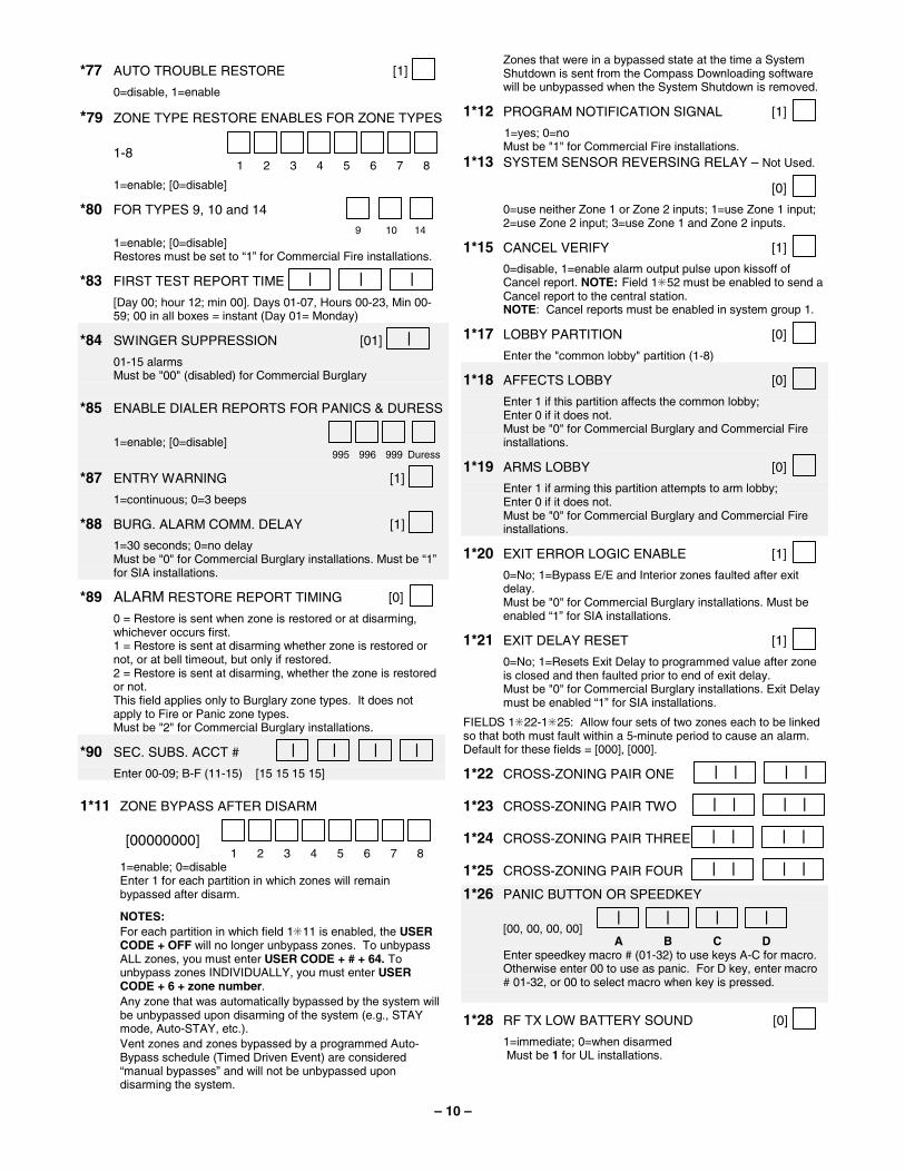
*77 AUTO TROUBLE RESTORE [1] 0=disable, 1=enable
*79 ZONE TYPE RESTORE ENABLES FOR ZONE TYPES
1-8 1
2
3
4
5
6
7
8
1=enable; [0=disable]
*80 FOR TYPES 9, 10 and 14 9 10 14 1=enable; [0=disable] Restores must be set to “1” for Commercial Fire installations.
*83 FIRST TEST REPORT TIME | | | [Day 00; hour 12; min 00]. Days 01-07, Hours 00-23, Min 00-
59; 00 in all boxes = instant (Day 01= Monday)
*84 SWINGER SUPPRESSION [01] | 01-15 alarms Must be "00" (disabled) for Commercial Burglary *85 ENABLE DIALER REPORTS FOR PANICS & DURESS
1=enable; [0=disable] 995
996
999
Duress
*87 ENTRY WARNING [1] 1=continuous; 0=3 beeps
*88 BURG. ALARM COMM. DELAY [1] 1=30 seconds; 0=no delay Must be "0" for Commercial Burglary installations. Must be “1”
for SIA installations.
*89 ALARM RESTORE REPORT TIMING [0] 0 = Restore is sent when zone is restored or at disarming, whichever occurs first. 1 = Restore is sent at disarming whether zone is restored or not, or at bell timeout, but only if restored. 2 = Restore is sent at disarming, whether the zone is restored or not.
This field applies only to Burglary zone types. It does not apply to Fire or Panic zone types.
Must be "2" for Commercial Burglary installations.
*90 SEC. SUBS. ACCT # | | | | Enter 00-09; B-F (11-15) [15 15 15 15] 1*11 ZONE BYPASS AFTER DISARM
[00000000] 1
2
3
4
5
6
7
8
1=enable; 0=disable Enter 1 for each partition in which zones will remain
bypassed after disarm.
NOTES: For each partition in which field 1✳11 is enabled, the USER CODE + OFF will no longer unbypass zones. To unbypass ALL zones, you must enter USER CODE + # + 64. To unbypass zones INDIVIDUALLY, you must enter USER CODE + 6 + zone number. Any zone that was automatically bypassed by the system will be unbypassed upon disarming of the system (e.g., STAY mode, Auto-STAY, etc.). Vent zones and zones bypassed by a programmed Auto-Bypass schedule (Timed Driven Event) are considered “manual bypasses” and will not be unbypassed upon disarming the system.
Zones that were in a bypassed state at the time a System Shutdown is sent from the Compass Downloading software will be unbypassed when the System Shutdown is removed.
1*12 PROGRAM NOTIFICATION SIGNAL [1] 1=yes; 0=no Must be "1" for Commercial Fire installations. 1*13 SYSTEM SENSOR REVERSING RELAY – Not Used.
[0] 0=use neither Zone 1 or Zone 2 inputs; 1=use Zone 1 input; 2=use Zone 2 input; 3=use Zone 1 and Zone 2 inputs.
1*15 CANCEL VERIFY [1] 0=disable, 1=enable alarm output pulse upon kissoff of
Cancel report. NOTE: Field 1✳52 must be enabled to send a Cancel report to the central station.
NOTE: Cancel reports must be enabled in system group 1.
1*17 LOBBY PARTITION [0] Enter the "common lobby" partition (1-8)
1*18 AFFECTS LOBBY [0] Enter 1 if this partition affects the common lobby; Enter 0 if it does not. Must be "0" for Commercial Burglary and Commercial Fire
installations.
1*19 ARMS LOBBY [0] Enter 1 if arming this partition attempts to arm lobby; Enter 0 if it does not. Must be "0" for Commercial Burglary and Commercial Fire
installations.
1*20 EXIT ERROR LOGIC ENABLE [1] 0=No; 1=Bypass E/E and Interior zones faulted after exit
delay. Must be "0" for Commercial Burglary installations. Must be
enabled “1” for SIA installations.
1*21 EXIT DELAY RESET [1] 0=No; 1=Resets Exit Delay to programmed value after zone
is closed and then faulted prior to end of exit delay. Must be "0" for Commercial Burglary installations. Exit Delay
must be enabled “1” for SIA installations.
FIELDS 1✳22-1✳25: Allow four sets of two zones each to be linked so that both must fault within a 5-minute period to cause an alarm. Default for these fields = [000], [000].
1*22 CROSS-ZONING PAIR ONE | | | |
1*23 CROSS-ZONING PAIR TWO | | | |
1*24 CROSS-ZONING PAIR THREE | | | |
1*25 CROSS-ZONING PAIR FOUR | | | | 1*26 PANIC BUTTON OR SPEEDKEY
[00, 00, 00, 00] |
A |
B |
C |
D
Enter speedkey macro # (01-32) to use keys A-C for macro. Otherwise enter 00 to use as panic. For D key, enter macro # 01-32, or 00 to select macro when key is pressed.
1*28 RF TX LOW BATTERY SOUND [0] 1=immediate; 0=when disarmed Must be 1 for UL installations.
– 11 –
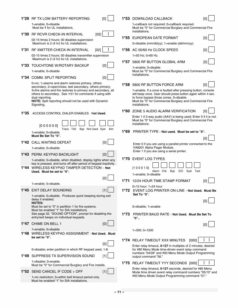
1*29 RF TX LOW BATTERY REPORTING [0] 1=enable; 0=disable Must be 1 for UL installations.
1*30 RF RCVR CHECK-IN INTERVAL [02] | 02-15 times 2 hours; 00 disables supervision Maximum is 2 (4 hr) for UL installations.
1*31 RF XMITTER CHECK-IN INTERVAL [02] | 02-15 times 2 hours; 00 disables transmitter supervision Maximum is 2 (4 hr) for UL installations.
1*33 TOUCHTONE W/ROTARY BACKUP [0] 1=enable; 0=disable
1*34 COMM. SPLIT REPORTING [0] 0=no; 1=alarms and alarm restores primary, others
secondary; 2=open/close, test secondary, others primary; 3=fire alarms and fire restores to primary and secondary, all others to secondary. See ✴51 for comments if using with dual reporting.
NOTE: Split reporting should not be used with Dynamic Signaling.
1*35 ACCESS CONTROL DIALER ENABLES - Not Used.
[0 0 0 0 0 0] Trace
Trbl
Byp
Not Used
Syst
Alm
1=enable; 0=disable Must Be Set To “0”.
1*42 CALL WAITING DEFEAT [0] 1=enable; 0=disable
1*43 PERM. KEYPAD BACKLIGHT [0] 1=enable; 0=disable, when disabled, display lights when any
key is pressed, and turns off after period of keypad inactivity. 1*44 WIRELESS KEYPAD TAMPER DETECTION – Not
Used. Must be set to “0”.
[0] 1=enable; 0=disable.
1*45 EXIT DELAY SOUNDING [1] 1=enable; 0=disable. Produces quick beeping during exit
delay if enabled. NOTES: Must be set to “0” in partition 1 for fire systems. Must be enabled “1” for SIA installations. See page 32, “SOUND OPTION”, prompt for disabling the
entry/exit beeps on individual keypads.
1*47 CHIME ON BELL 1 [0] 1=enable; 0=disable 1*48 WIRELESS KEYPAD ASSIGNMENT - Not Used. Must
be set to “0”.
[0] 0=disable; enter partition in which RF keypad used, 1-8.
1*49 SUPPRESS TX SUPERVISION SOUND [1] 1=disable; 0=enable. Must be "0" for Commercial Burglary and Fire installs.
1*52 SEND CANCEL IF CODE + OFF [1] 1=no restriction; 0=within bell timeout period only. Must be enabled “1” for SIA installations.
1*53 DOWNLOAD CALLBACK [0] 1=callback not required; 0=callback required. Must be "0" for Commercial Burglary and Commercial Fire
installations.
1*55 EUROPEAN DATE FORMAT [0] 0=disable (mm/dd/yy); 1=enable (dd/mm/yy).
1*56 AC 50/60 Hz CLOCK SPEED [0] 1=50 Hz; 0=60 Hz.
1*57 5800 RF BUTTON GLOBAL ARM [0] 1=enable; 0=disable Must be "0" for Commercial Burglary and Commercial Fire
installations.
1*58 5800 RF BUTTON FORCE ARM [0] 1=enable. If a zone is faulted after pressing button, console
will beep once. User should press button again within 4 sec. to force bypass those zones. 0=disable.
Must be "0" for Commercial Burglary and Commercial Fire installations.
1*60 ZONE 5 AUDIO ALARM VERIFICATION [0] Enter 1 if 2-way audio (AAV) is being used; Enter 0 if it is not. Must be "0" for Commercial Burglary and Commercial Fire
installations. 1*69 PRINTER TYPE - Not used. Must be set to “0”.
[0] Enter 0 if you are using a parallel printer connected to the
VA8201 Alpha Pager Module. Enter 1 if you are using a serial printer. 1*70 EVENT LOG TYPES
[1 0 0 0 1 0]
Alarm
Chk
Byp
O/C
Syst
Test
1=enable; 0=disable
1*71 12/24 HOUR TIME STAMP FORMAT [0] 0=12 hour; 1=24 hour 1*72 EVENT LOG PRINTER ON-LINE - Not Used. Must Be
Set To “0”.
[0] 0=disable; 1=enable 1*73 PRINTER BAUD RATE - Not Used. Must Be Set To
“0”..
[0] 1=300; 0=1200
1*74 RELAY TIMEOUT XXX MINUTES [000] | | Enter relay timeout, 0-127 in multiples of 2 minutes, desired
for #80 Menu Mode time-driven event relay command numbers "04/09" and #93 Menu Mode Output Programming output command "56."
1*75 RELAY TIMEOUT YYY SECONDS [000] | | Enter relay timeout, 0-127 seconds, desired for #80 Menu Mode time driven event relay command numbers "05/10" and
#93 Menu Mode Output Programming command "57."
– 12 –
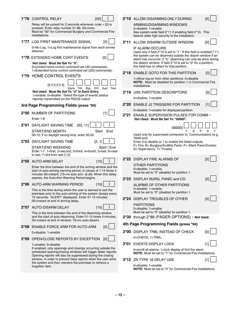
1*76 CONTROL RELAY [00] | Relay will be pulsed for 2 seconds whenever code + [0] is
pressed. Enter relay number 01-96; 00=none. Must be "00" for Commercial Burglary and Commercial Fire
installations.
1*77 LOG FIRST MAINTENANCE SIGNAL [0] 0=No Log; 1=Log first maintenance signal from each smoke
detector.
1*78 EXTENDED HOME CONT EVENTS [0] Not Used. Must Be Set To “0”. 0=Limited home control command set (32 commands). 1=Extended home control command set (255 commands).
1*79 HOME CONTROL EVENTS
[0 0 0 0 0 0]
Alarm
Trbl
Byp
O/C
Syst
Test
Not Used. Must Be Set To “0” In Each Entry. 1=enable; 0=disable. Select the type of events (status
reports) transmitted via the RS232 output.
3rd Page Programming Fields (press *94)
2*00 NUMBER OF PARTITIONS [1] Enter 1-8
2*01 DAYLIGHT SAVING TIME [03, 11] | | START/END MONTH Start End 00-12; if no daylight saving time, enter 00,00
2*02 DAYLIGHT SAVING TIME [2, 1] | START/END WEEKEND Start | End Enter 1-7. 1=first; 2=second; 3=third; 4=fourth; 5=last; 6=next
to last; 7=3rd from last [1,5]
2*05 AUTO-ARM DELAY [15] | Enter the time between the end of the arming window and the
start of auto-arming warning period, in values of 1-14 times 4 minutes 00=instant; [15=no auto arm at all]. When this delay expires, the Auto-Arm Warning Period begins.
2*06 AUTO-ARM WARNING PERIOD [15] | This is the time during which the user is warned to exit the
premises prior to the auto-arming of the system (beeps every 15 seconds; "ALERT" displayed). Enter 01-15 minutes. 00=instant at end of arming delay.
2*07 AUTO-DISARM DELAY [15] | This is the time between the end of the disarming window
and the start of auto-disarming. Enter 01-14 times 4 minutes; 00=instant at end of window; 15=no auto-disarm.
2*08 ENABLE FORCE ARM FOR AUTO-ARM [0] 0=disable; 1=enable
2*09 OPEN/CLOSE REPORTS BY EXCEPTION [0] 1=enable; 0=disable If enabled, only openings and closings occurring outside the
scheduled opening/closing windows will trigger dialer reports. Opening reports will also be suppressed during the closing window, in order to prevent false reports when the user arms the system and then reenters the premises to retrieve a forgotten item.
2*10 ALLOW DISARMING ONLY DURING [0] ARMING/DISARMING WINDOWS 0=disable; 1=enable See system-wide field 2*11 if enabling field 2*10. This
feature adds high security to the installation.
2*11 ALLOW DISARM OUTSIDE WINDOW [0] IF ALARM OCCURS Used only if field 2*10 is set to "1." If this field is enabled ("1")
the system can be disarmed outside the disarm window if an alarm has occurred. If "0," disarming can only be done during the disarm window. If field 2*10 is set to "0" for a partition, this field has no effect for that partition.
2*18 ENABLE GOTO FOR THIS PARTITION [0] 1=Allow log-on from other partitions; 0=disable NOTE: Must be disabled for partition 1 in Commercial Fire
installations.
2*19 USE PARTITION DESCRIPTORS [0] 0=disable; 1=enable
2*20 ENABLE J2 TRIGGERS FOR PARTITION [1] 0=disable; 1=enable for displayed partition
2*21 ENABLE SUPERVISION PULSES FOR COMM - Not Used. Must Be Set To “00000”.
00000] F
B
P
S
T
Used only for supervised connection to Communicators (e.g. 7845i-ent).
Enter 0 to disable or 1 to enable the listed outputs. F= Fire; B= Burglary/Audible Panic; P= Silent Panic/Duress;
S= Supervisory; T= Trouble.
2*22 DISPLAY FIRE ALARMS OF [0] OTHER PARTITIONS 0=disable; 1=enable. Must be set to “0” (disable) for partition 1.
2*23 DISPLAY BURG, PANIC and CO [0] ALARMS OF OTHER PARTITIONS 0=disable; 1=enable. Must be set to “0” (disable) for partition 1.
2*24 DISPLAY TROUBLES OF OTHER [0] PARTITIONS 0=disable; 1=enable Must be set to “0” (disable) for partition 1.
2*30 through 2*88 (PAGER OPTIONS) - Not Used.
4th Page Programming Fields (press *94)
3*00 DISPLAY TRBL INSTEAD OF CHECK [0] 0=CHECK; 1=TRBL
3*01 EVENTS DISPLAY LOCK [1] 0=scroll all alarms; 1=lock display of first fire alarm NOTE: Must be set to “1” for Commercial Fire Installations.
3*12 ZN TYPE 18 DELAY USE [1] 0=disable; 1=enable NOTE: Must be set to “0” for Commercial Fire Installations.
– 13 –
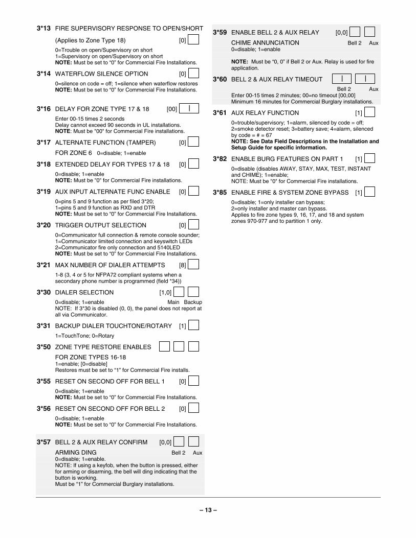
3*13 FIRE SUPERVISORY RESPONSE TO OPEN/SHORT
(Applies to Zone Type 18) [0] 0=Trouble on open/Supervisory on short 1=Supervisory on open/Supervisory on short NOTE: Must be set to “0” for Commercial Fire Installations.
3*14 WATERFLOW SILENCE OPTION [0] 0=silence on code = off; 1=silence when waterflow restores NOTE: Must be set to “0” for Commercial Fire Installations.
3*16 DELAY FOR ZONE TYPE 17 & 18 [00] | Enter 00-15 times 2 seconds Delay cannot exceed 90 seconds in UL installations. NOTE: Must be "00" for Commercial Fire installations.
3*17 ALTERNATE FUNCTION (TAMPER) [0] FOR ZONE 6 0=disable; 1=enable
3*18 EXTENDED DELAY FOR TYPES 17 & 18 [0] 0=disable; 1=enable NOTE: Must be "0" for Commercial Fire installations.
3*19 AUX INPUT ALTERNATE FUNC ENABLE [0] 0=pins 5 and 9 function as per filed 3*20; 1=pins 5 and 9 function as RXD and DTR NOTE: Must be set to “0” for Commercial Fire Installations.
3*20 TRIGGER OUTPUT SELECTION [0] 0=Communicator full connection & remote console sounder; 1=Communicator limited connection and keyswitch LEDs 2=Communicator fire only connection and 5140LED NOTE: Must be set to “0” for Commercial Fire Installations.
3*21 MAX NUMBER OF DIALER ATTEMPTS [8] 1-8 (3, 4 or 5 for NFPA72 compliant systems when a
secondary phone number is programmed (field *34))
3*30 DIALER SELECTION [1,0] 0=disable; 1=enable Main Backup NOTE: If 3*30 is disabled (0, 0), the panel does not report at
all via Communicator.
3*31 BACKUP DIALER TOUCHTONE/ROTARY [1] 1=TouchTone; 0=Rotary
3*50 ZONE TYPE RESTORE ENABLES FOR ZONE TYPES 16-18 1=enable; [0=disable] Restores must be set to “1” for Commercial Fire installs.
3*55 RESET ON SECOND OFF FOR BELL 1 [0] 0=disable; 1=enable NOTE: Must be set to “0” for Commercial Fire Installations.
3*56 RESET ON SECOND OFF FOR BELL 2 [0] 0=disable; 1=enable NOTE: Must be set to “0” for Commercial Fire Installations.
3*57 BELL 2 & AUX RELAY CONFIRM [0,0] ARMING DING Bell 2 Aux 0=disable; 1=enable. NOTE: If using a keyfob, when the button is pressed, either
for arming or disarming, the bell will ding indicating that the button is working.
Must be “1” for Commercial Burglary installations.
3*59 ENABLE BELL 2 & AUX RELAY [0,0] CHIME ANNUNCIATION Bell 2 Aux 0=disable; 1=enable NOTE: Must be “0, 0” if Bell 2 or Aux. Relay is used for fire
application.
3*60 BELL 2 & AUX RELAY TIMEOUT | | Bell 2 Aux Enter 00-15 times 2 minutes; 00=no timeout [00,00] Minimum 16 minutes for Commercial Burglary installations.
3*61 AUX RELAY FUNCTION [1] 0=trouble/supervisory; 1=alarm, silenced by code = off;
2=smoke detector reset; 3=battery save; 4=alarm, silenced by code = # = 67
NOTE: See Data Field Descriptions in the Installation and Setup Guide for specific information.
3*82 ENABLE BURG FEATURES ON PART 1 [1] 0=disable (disables AWAY, STAY, MAX, TEST, INSTANT
and CHIME); 1=enable; NOTE: Must be "0" for Commercial Fire installations.
3*85 ENABLE FIRE & SYSTEM ZONE BYPASS [1] 0=disable; 1=only installer can bypass; 2=only installer and master can bypass. Applies to fire zone types 9, 16, 17, and 18 and system
zones 970-977 and to partition 1 only.
– 14 –
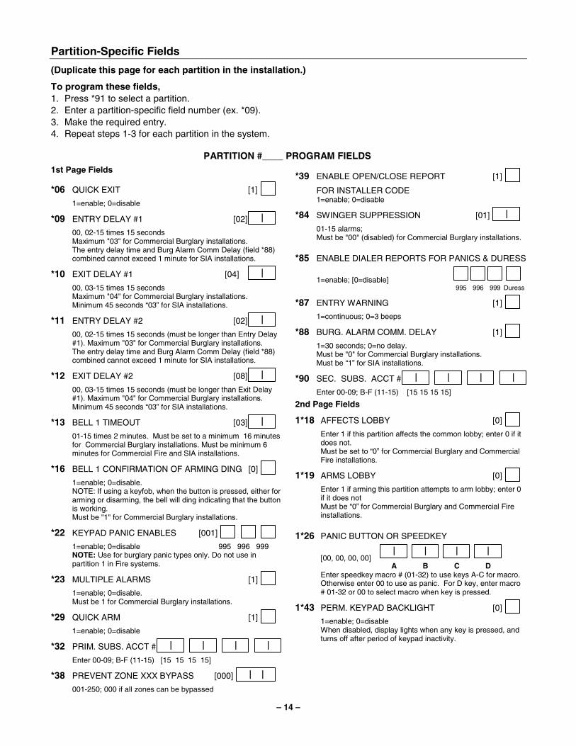
Partition-Specific Fields
(Duplicate this page for each partition in the installation.)
To program these fields, 1. Press *91 to select a partition. 2. Enter a partition-specific field number (ex. *09). 3. Make the required entry. 4. Repeat steps 1-3 for each partition in the system.
PARTITION #____ PROGRAM FIELDS 1st Page Fields
*06 QUICK EXIT [1] 1=enable; 0=disable
*09 ENTRY DELAY #1 [02] | 00, 02-15 times 15 seconds Maximum "03" for Commercial Burglary installations. The entry delay time and Burg Alarm Comm Delay (field *88)
combined cannot exceed 1 minute for SIA installations.
*10 EXIT DELAY #1 [04] | 00, 03-15 times 15 seconds Maximum "04" for Commercial Burglary installations. Minimum 45 seconds “03” for SIA installations.
*11 ENTRY DELAY #2 [02] | 00, 02-15 times 15 seconds (must be longer than Entry Delay
#1). Maximum "03" for Commercial Burglary installations. The entry delay time and Burg Alarm Comm Delay (field *88)
combined cannot exceed 1 minute for SIA installations.
*12 EXIT DELAY #2 [08] | 00, 03-15 times 15 seconds (must be longer than Exit Delay
#1). Maximum "04" for Commercial Burglary installations. Minimum 45 seconds “03” for SIA installations.
*13 BELL 1 TIMEOUT [03] | 01-15 times 2 minutes. Must be set to a minimum 16 minutes
for Commercial Burglary installations. Must be minimum 6 minutes for Commercial Fire and SIA installations.
*16 BELL 1 CONFIRMATION OF ARMING DING [0] 1=enable; 0=disable. NOTE: If using a keyfob, when the button is pressed, either for
arming or disarming, the bell will ding indicating that the button is working.
Must be "1" for Commercial Burglary installations.
*22 KEYPAD PANIC ENABLES [001] 1=enable; 0=disable 995 996 999 NOTE: Use for burglary panic types only. Do not use in
partition 1 in Fire systems.
*23 MULTIPLE ALARMS [1] 1=enable; 0=disable. Must be 1 for Commercial Burglary installations.
*29 QUICK ARM [1] 1=enable; 0=disable
*32 PRIM. SUBS. ACCT # | | | | Enter 00-09; B-F (11-15) [15 15 15 15]
*38 PREVENT ZONE XXX BYPASS [000] | | 001-250; 000 if all zones can be bypassed
*39 ENABLE OPEN/CLOSE REPORT [1] FOR INSTALLER CODE 1=enable; 0=disable
*84 SWINGER SUPPRESSION [01] | 01-15 alarms; Must be "00" (disabled) for Commercial Burglary installations. *85 ENABLE DIALER REPORTS FOR PANICS & DURESS
1=enable; [0=disable] 995
996
999
Duress
*87 ENTRY WARNING [1] 1=continuous; 0=3 beeps
*88 BURG. ALARM COMM. DELAY [1] 1=30 seconds; 0=no delay. Must be "0" for Commercial Burglary installations. Must be “1” for SIA installations.
*90 SEC. SUBS. ACCT # | | | | Enter 00-09; B-F (11-15) [15 15 15 15]
2nd Page Fields
1*18 AFFECTS LOBBY [0] Enter 1 if this partition affects the common lobby; enter 0 if it
does not. Must be set to “0” for Commercial Burglary and Commercial
Fire installations.
1*19 ARMS LOBBY [0] Enter 1 if arming this partition attempts to arm lobby; enter 0
if it does not Must be “0” for Commercial Burglary and Commercial Fire
installations. 1*26 PANIC BUTTON OR SPEEDKEY
[00, 00, 00, 00] |
A |
B |
C |
D
Enter speedkey macro # (01-32) to use keys A-C for macro. Otherwise enter 00 to use as panic. For D key, enter macro # 01-32 or 00 to select macro when key is pressed.
1*43 PERM. KEYPAD BACKLIGHT [0] 1=enable; 0=disable When disabled, display lights when any key is pressed, and
turns off after period of keypad inactivity.
– 15 –
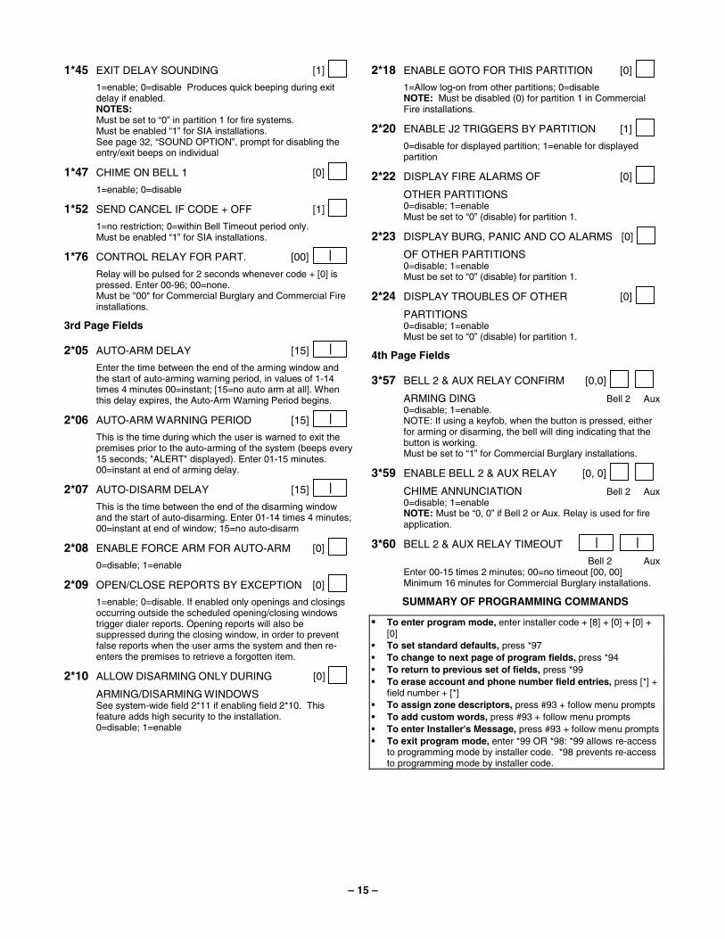
1*45 EXIT DELAY SOUNDING [1] 1=enable; 0=disable Produces quick beeping during exit
delay if enabled. NOTES: Must be set to “0” in partition 1 for fire systems. Must be enabled “1” for SIA installations. See page 32, “SOUND OPTION”, prompt for disabling the
entry/exit beeps on individual
1*47 CHIME ON BELL 1 [0] 1=enable; 0=disable
1*52 SEND CANCEL IF CODE + OFF [1] 1=no restriction; 0=within Bell Timeout period only. Must be enabled “1” for SIA installations.
1*76 CONTROL RELAY FOR PART. [00] |
Relay will be pulsed for 2 seconds whenever code + [0] is pressed. Enter 00-96; 00=none.
Must be "00" for Commercial Burglary and Commercial Fire installations.
3rd Page Fields
2*05 AUTO-ARM DELAY [15] | Enter the time between the end of the arming window and
the start of auto-arming warning period, in values of 1-14 times 4 minutes 00=instant; [15=no auto arm at all]. When this delay expires, the Auto-Arm Warning Period begins.
2*06 AUTO-ARM WARNING PERIOD [15] | This is the time during which the user is warned to exit the
premises prior to the auto-arming of the system (beeps every 15 seconds; "ALERT" displayed). Enter 01-15 minutes. 00=instant at end of arming delay.
2*07 AUTO-DISARM DELAY [15] | This is the time between the end of the disarming window
and the start of auto-disarming. Enter 01-14 times 4 minutes; 00=instant at end of window; 15=no auto-disarm
2*08 ENABLE FORCE ARM FOR AUTO-ARM [0] 0=disable; 1=enable
2*09 OPEN/CLOSE REPORTS BY EXCEPTION [0] 1=enable; 0=disable. If enabled only openings and closings
occurring outside the scheduled opening/closing windows trigger dialer reports. Opening reports will also be suppressed during the closing window, in order to prevent false reports when the user arms the system and then re-enters the premises to retrieve a forgotten item.
2*10 ALLOW DISARMING ONLY DURING [0] ARMING/DISARMING WINDOWS See system-wide field 2*11 if enabling field 2*10. This
feature adds high security to the installation. 0=disable; 1=enable
2*18 ENABLE GOTO FOR THIS PARTITION [0] 1=Allow log-on from other partitions; 0=disable NOTE: Must be disabled (0) for partition 1 in Commercial
Fire installations.
2*20 ENABLE J2 TRIGGERS BY PARTITION [1] 0=disable for displayed partition; 1=enable for displayed
partition
2*22 DISPLAY FIRE ALARMS OF [0] OTHER PARTITIONS 0=disable; 1=enable Must be set to “0” (disable) for partition 1.
2*23 DISPLAY BURG, PANIC AND CO ALARMS [0] OF OTHER PARTITIONS 0=disable; 1=enable Must be set to “0” (disable) for partition 1.
2*24 DISPLAY TROUBLES OF OTHER [0] PARTITIONS 0=disable; 1=enable Must be set to “0” (disable) for partition 1.
4th Page Fields
3*57 BELL 2 & AUX RELAY CONFIRM [0,0] ARMING DING Bell 2 Aux 0=disable; 1=enable. NOTE: If using a keyfob, when the button is pressed, either
for arming or disarming, the bell will ding indicating that the button is working.
Must be set to “1” for Commercial Burglary installations.
3*59 ENABLE BELL 2 & AUX RELAY [0, 0] CHIME ANNUNCIATION Bell 2 Aux 0=disable; 1=enable NOTE: Must be “0, 0” if Bell 2 or Aux. Relay is used for fire
application.
3*60 BELL 2 & AUX RELAY TIMEOUT | | Bell 2 Aux Enter 00-15 times 2 minutes; 00=no timeout [00, 00] Minimum 16 minutes for Commercial Burglary installations.
SUMMARY OF PROGRAMMING COMMANDS
• To enter program mode, enter installer code + [8] + [0] + [0] + [0]
• To set standard defaults, press *97 • To change to next page of program fields, press *94 • To return to previous set of fields, press *99 • To erase account and phone number field entries, press [*] +
field number + [*] • To assign zone descriptors, press #93 + follow menu prompts • To add custom words, press #93 + follow menu prompts • To enter Installer's Message, press #93 + follow menu prompts • To exit program mode, enter *99 OR *98: *99 allows re-access
to programming mode by installer code. *98 prevents re-access to programming mode by installer code.
– 16 –
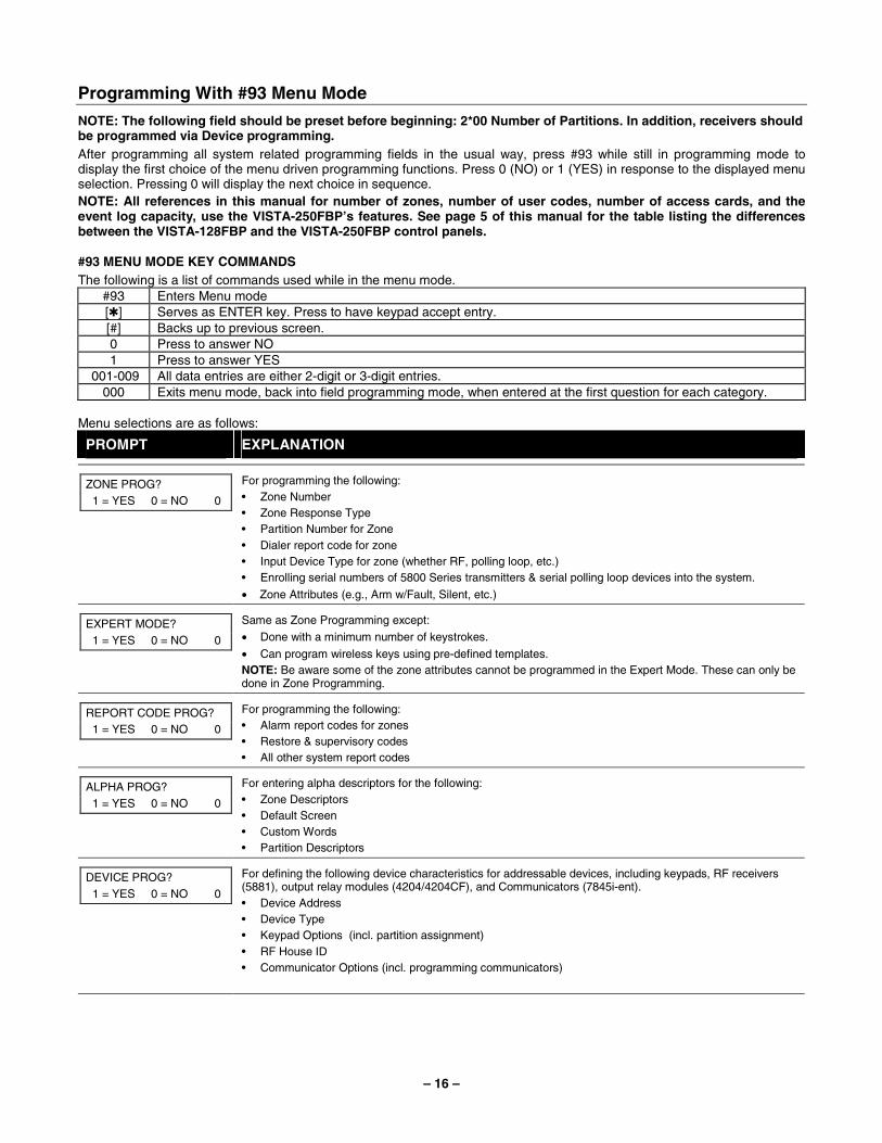
Programming With #93 Menu Mode
NOTE: The following field should be preset before beginning: 2*00 Number of Partitions. In addition, receivers should be programmed via Device programming. After programming all system related programming fields in the usual way, press #93 while still in programming mode to display the first choice of the menu driven programming functions. Press 0 (NO) or 1 (YES) in response to the displayed menu selection. Pressing 0 will display the next choice in sequence. NOTE: All references in this manual for number of zones, number of user codes, number of access cards, and the event log capacity, use the VISTA-250FBP’s features. See page 5 of this manual for the table listing the differences between the VISTA-128FBP and the VISTA-250FBP control panels.
#93 MENU MODE KEY COMMANDS The following is a list of commands used while in the menu mode.
#93 Enters Menu mode [✱] Serves as ENTER key. Press to have keypad accept entry. [#] Backs up to previous screen. 0 Press to answer NO 1 Press to answer YES
001-009 All data entries are either 2-digit or 3-digit entries. 000 Exits menu mode, back into field programming mode, when entered at the first question for each category.
Menu selections are as follows:
PROMPT EXPLANATION
ZONE PROG? 1 = YES 0 = NO 0
For programming the following: • Zone Number • Zone Response Type • Partition Number for Zone • Dialer report code for zone • Input Device Type for zone (whether RF, polling loop, etc.) • Enrolling serial numbers of 5800 Series transmitters & serial polling loop devices into the system.
• Zone Attributes (e.g., Arm w/Fault, Silent, etc.)
EXPERT MODE? 1 = YES 0 = NO 0
Same as Zone Programming except:
• Done with a minimum number of keystrokes.
• Can program wireless keys using pre-defined templates. NOTE: Be aware some of the zone attributes cannot be programmed in the Expert Mode. These can only be done in Zone Programming.
REPORT CODE PROG? 1 = YES 0 = NO 0
For programming the following: • Alarm report codes for zones • Restore & supervisory codes • All other system report codes
ALPHA PROG? 1 = YES 0 = NO 0
For entering alpha descriptors for the following: • Zone Descriptors • Default Screen • Custom Words • Partition Descriptors
DEVICE PROG? 1 = YES 0 = NO 0
For defining the following device characteristics for addressable devices, including keypads, RF receivers (5881), output relay modules (4204/4204CF), and Communicators (7845i-ent). • Device Address • Device Type • Keypad Options (incl. partition assignment) • RF House ID • Communicator Options (incl. programming communicators)
– 17 –
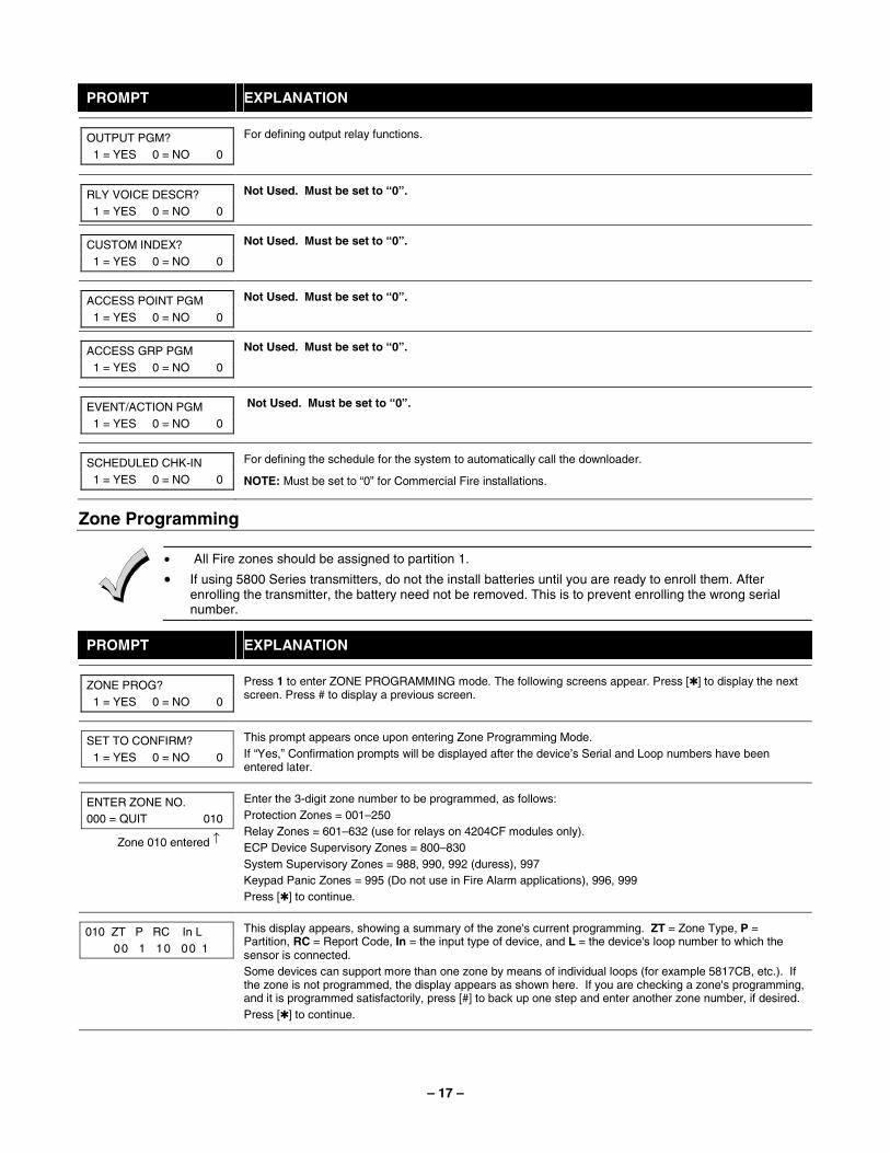
PROMPT EXPLANATION
OUTPUT PGM? 1 = YES 0 = NO 0
For defining output relay functions.
RLY VOICE DESCR? 1 = YES 0 = NO 0
Not Used. Must be set to “0”.
CUSTOM INDEX? 1 = YES 0 = NO 0
Not Used. Must be set to “0”.
ACCESS POINT PGM 1 = YES 0 = NO 0
Not Used. Must be set to “0”.
ACCESS GRP PGM 1 = YES 0 = NO 0
Not Used. Must be set to “0”.
EVENT/ACTION PGM 1 = YES 0 = NO 0
Not Used. Must be set to “0”.
SCHEDULED CHK-IN 1 = YES 0 = NO 0
For defining the schedule for the system to automatically call the downloader.
NOTE: Must be set to “0” for Commercial Fire installations.
Zone Programming
• All Fire zones should be assigned to partition 1.
• If using 5800 Series transmitters, do not the install batteries until you are ready to enroll them. After enrolling the transmitter, the battery need not be removed. This is to prevent enrolling the wrong serial number.
PROMPT EXPLANATION
ZONE PROG? 1 = YES 0 = NO 0
Press 1 to enter ZONE PROGRAMMING mode. The following screens appear. Press [✱] to display the next screen. Press # to display a previous screen.
SET TO CONFIRM? 1 = YES 0 = NO 0
This prompt appears once upon entering Zone Programming Mode. If “Yes,” Confirmation prompts will be displayed after the device’s Serial and Loop numbers have been entered later.
ENTER ZONE NO. 000 = QUIT 010
Zone 010 entered ↑
Enter the 3-digit zone number to be programmed, as follows: Protection Zones = 001–250 Relay Zones = 601–632 (use for relays on 4204CF modules only). ECP Device Supervisory Zones = 800–830 System Supervisory Zones = 988, 990, 992 (duress), 997 Keypad Panic Zones = 995 (Do not use in Fire Alarm applications), 996, 999 Press [✱] to continue.
010 ZT P RC In L 00 1 10 00 1
This display appears, showing a summary of the zone's current programming. ZT = Zone Type, P = Partition, RC = Report Code, In = the input type of device, and L = the device's loop number to which the sensor is connected. Some devices can support more than one zone by means of individual loops (for example 5817CB, etc.). If the zone is not programmed, the display appears as shown here. If you are checking a zone's programming, and it is programmed satisfactorily, press [#] to back up one step and enter another zone number, if desired. Press [✱] to continue.
– 18 –
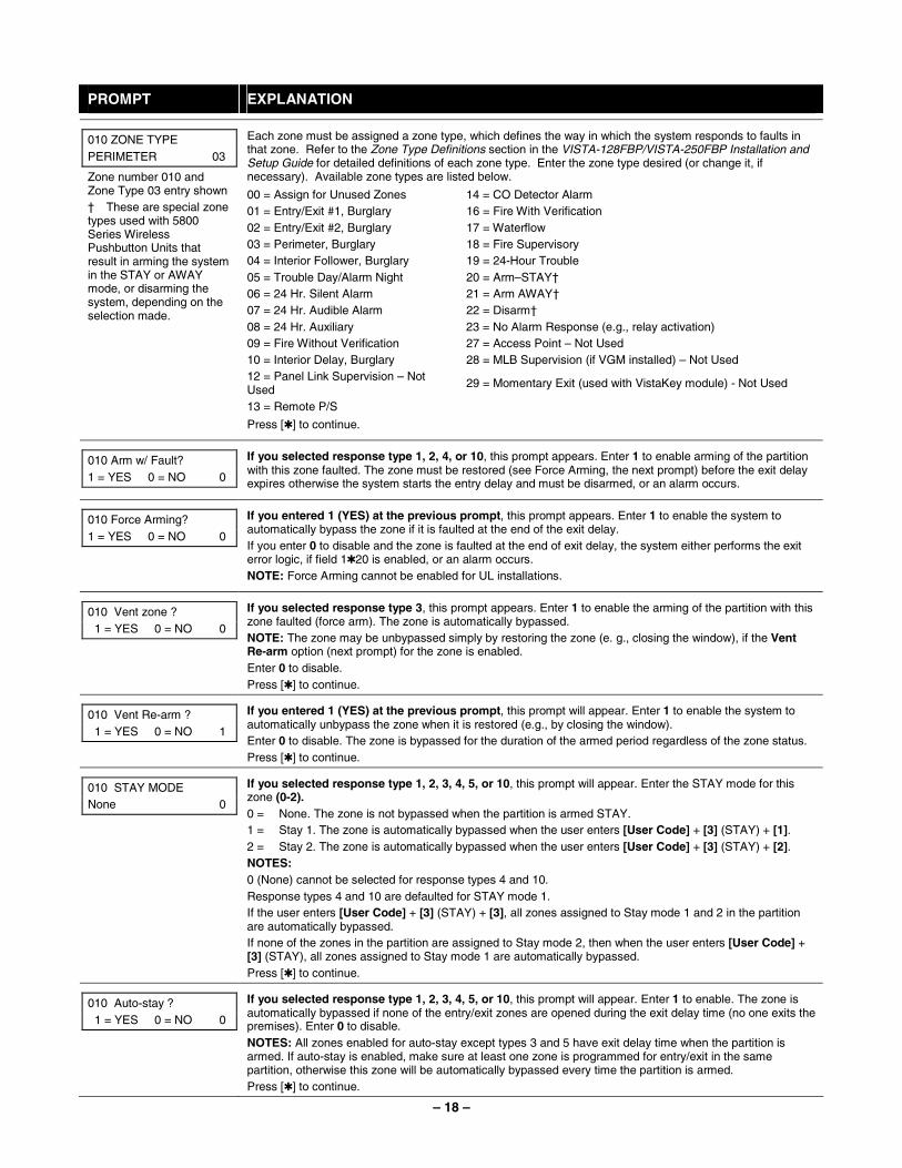
PROMPT EXPLANATION
Each zone must be assigned a zone type, which defines the way in which the system responds to faults in that zone. Refer to the Zone Type Definitions section in the VISTA-128FBP/VISTA-250FBP Installation and Setup Guide for detailed definitions of each zone type. Enter the zone type desired (or change it, if necessary). Available zone types are listed below.
00 = Assign for Unused Zones 14 = CO Detector Alarm 01 = Entry/Exit #1, Burglary 16 = Fire With Verification 02 = Entry/Exit #2, Burglary 17 = Waterflow 03 = Perimeter, Burglary 18 = Fire Supervisory 04 = Interior Follower, Burglary 19 = 24-Hour Trouble 05 = Trouble Day/Alarm Night 20 = Arm–STAY† 06 = 24 Hr. Silent Alarm 21 = Arm AWAY† 07 = 24 Hr. Audible Alarm 22 = Disarm† 08 = 24 Hr. Auxiliary 23 = No Alarm Response (e.g., relay activation) 09 = Fire Without Verification 27 = Access Point – Not Used 10 = Interior Delay, Burglary 28 = MLB Supervision (if VGM installed) – Not Used 12 = Panel Link Supervision – Not Used 29 = Momentary Exit (used with VistaKey module) - Not Used
13 = Remote P/S
010 ZONE TYPE PERIMETER 03
Zone number 010 and Zone Type 03 entry shown † These are special zone types used with 5800 Series Wireless Pushbutton Units that result in arming the system in the STAY or AWAY mode, or disarming the system, depending on the selection made.
Press [✱] to continue.
010 Arm w/ Fault? 1 = YES 0 = NO 0
If you selected response type 1, 2, 4, or 10, this prompt appears. Enter 1 to enable arming of the partition with this zone faulted. The zone must be restored (see Force Arming, the next prompt) before the exit delay expires otherwise the system starts the entry delay and must be disarmed, or an alarm occurs.
010 Force Arming? 1 = YES 0 = NO 0
If you entered 1 (YES) at the previous prompt, this prompt appears. Enter 1 to enable the system to automatically bypass the zone if it is faulted at the end of the exit delay. If you enter 0 to disable and the zone is faulted at the end of exit delay, the system either performs the exit error logic, if field 1✱20 is enabled, or an alarm occurs. NOTE: Force Arming cannot be enabled for UL installations.
010 Vent zone ? 1 = YES 0 = NO 0
If you selected response type 3, this prompt appears. Enter 1 to enable the arming of the partition with this zone faulted (force arm). The zone is automatically bypassed. NOTE: The zone may be unbypassed simply by restoring the zone (e. g., closing the window), if the Vent Re-arm option (next prompt) for the zone is enabled. Enter 0 to disable. Press [✱] to continue.
010 Vent Re-arm ? 1 = YES 0 = NO 1
If you entered 1 (YES) at the previous prompt, this prompt will appear. Enter 1 to enable the system to automatically unbypass the zone when it is restored (e.g., by closing the window). Enter 0 to disable. The zone is bypassed for the duration of the armed period regardless of the zone status. Press [✱] to continue.
010 STAY MODE None 0
If you selected response type 1, 2, 3, 4, 5, or 10, this prompt will appear. Enter the STAY mode for this zone (0-2). 0 = None. The zone is not bypassed when the partition is armed STAY. 1 = Stay 1. The zone is automatically bypassed when the user enters [User Code] + [3] (STAY) + [1]. 2 = Stay 2. The zone is automatically bypassed when the user enters [User Code] + [3] (STAY) + [2]. NOTES: 0 (None) cannot be selected for response types 4 and 10. Response types 4 and 10 are defaulted for STAY mode 1. If the user enters [User Code] + [3] (STAY) + [3], all zones assigned to Stay mode 1 and 2 in the partition are automatically bypassed. If none of the zones in the partition are assigned to Stay mode 2, then when the user enters [User Code] + [3] (STAY), all zones assigned to Stay mode 1 are automatically bypassed. Press [✱] to continue.
010 Auto-stay ? 1 = YES 0 = NO 0
If you selected response type 1, 2, 3, 4, 5, or 10, this prompt will appear. Enter 1 to enable. The zone is automatically bypassed if none of the entry/exit zones are opened during the exit delay time (no one exits the premises). Enter 0 to disable. NOTES: All zones enabled for auto-stay except types 3 and 5 have exit delay time when the partition is armed. If auto-stay is enabled, make sure at least one zone is programmed for entry/exit in the same partition, otherwise this zone will be automatically bypassed every time the partition is armed. Press [✱] to continue.
– 19 –
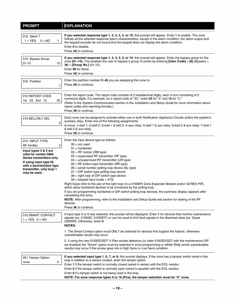
PROMPT EXPLANATION
010 Silent ? 1 = YES 0 = NO 1
If you selected response type 1, 2, 3, 4, 5, or 10, this prompt will appear. Enter 1 to enable. The zone follows all the selected response type’s characteristics, except in the alarm condition, the alarm output and the keypad sounder do not sound and the keypad does not display the alarm condition. Enter 0 to disable. Press [✱] to continue.
010 Bypass Group 01-15 01
If you selected response type 1, 2, 3, 4, 5, or 10, this prompt will appear. Enter the bypass group for the zone (01–15). This enables the user to bypass a group of zones by entering [User Code] + [6] (Bypass) + [✱] + [Group No.] (01-15). Enter 00 for None. Press [✱] to continue.
010 Partition 1
Enter the partition number (1–8) you are assigning this zone to. Press [✱] to continue.
010 REPORT CODE 1st 03 2nd 12 3C
Enter the report code. The report code consists of 2 hexadecimal digits, each in turn consisting of 2 numerical digits. For example, for a report code of "3C," enter 03 for "3" and 12 for "C." (Refer to the System Communication section in the Installation and Setup Guide for more information about report codes and reporting formats.) Press [✱] to continue.
010 BELL/RLY SEL 0
Each zone can be assigned to activate either one or both Notification Appliance Circuits and/or the system’s auxiliary relay. Enter one of the following assignments: 0=none; 1=bell 1; 2=bell 2; 3=bell 1 & bell 2; 4=aux relay; 5=bell 1 & aux relay; 6=bell 2 & aux relay; 7=bell 1 & bell 2 & aux relay. Press [✱] to continue.
010 INPUT TYPE RF Xmitter 3
Input types 4 & 5 are valid for certain 5800 Series transmitters only If using input type 02 with a door/window type transmitter, only loop 1 may be used.
Enter the input device type as follows: 00 = not used 01 = hardwired 02 = RF motion (RM type) 03 = supervised RF transmitter (RF type) 04 = unsupervised RF transmitter (UR type) 05 = RF button-type transmitter (BR type) 06 = serial number polling loop device (SL type) 07 = DIP switch-type polling loop device 08 = right loop of DIP switch type device 09 = keypad input (code + #73)
Right loops refer to the use of the right loop on a 4190WH Zone Expander Module and/or 4278EX PIR, which allow hardwired devices to be monitored by the polling loop. If you are programming hardwired or DIP switch polling loop devices, the summary display appears after completing this entry. NOTE: After programming, refer to the Installation and Setup Guide test section for testing of the RF devices. Press [✱] to continue.
010 SMART CONTACT 1 = YES 0 = NO
If input type 3 or 6 was selected, this prompt will be displayed. Enter 1 for devices that monitor maintenance signals (ex. 5193SD, 5193SDT) or can be used to limit fault signals in the disarmed state (ex. Quest 2260SN). Otherwise, enter 0. NOTES:
1. The Smart Contact option must ONLY be selected for devices that support the feature, otherwise unpredictable results may occur.
2. if using the new 5193SD/SDT V-Plex smoke detectors (or older 5192SD/SDT with the maintenance DIP sw enabled) the "Smart" option must be selected in zone programming or when they enroll unpredictable results may occur if the smoke goes into a High Sens or Low Sens condition.
001 Tamper Option none 0
If you selected input type 1, 6, 7, or 8, this prompt displays. If the zone has a tamper switch wired in the loop in addition to a sensor contact, enter the tamper option. Enter 1 if the tamper switch is normally closed (wired in series) with the EOL resistor. Enter 2 if the tamper switch is normally open (wired in parallel) with the EOL resistor. Enter 0 if a tamper switch is not being used in the loop. NOTE: For zone response types 9 or 16 (Fire), the tamper selection must be “0” none.
– 20 –
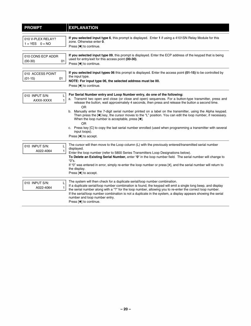
PROMPT EXPLANATION
010 V-PLEX RELAY? 1 = YES 0 = NO
If you selected input type 6, this prompt is displayed. Enter 1 if using a 4101SN Relay Module for this zone. Otherwise enter 0. Press [✱] to continue.
010 CONS ECP ADDR (00-30) 01
If you selected input type 09, this prompt is displayed. Enter the ECP address of the keypad that is being used for entry/exit for this access point (00-30). Press [✱] to continue.
010 ACCESS POINT (01-15) 01
If you selected input types 06 this prompt is displayed. Enter the access point (01-15) to be controlled by the input type. NOTE: For input type 06, the selected address must be 00. Press [✱] to continue.
010 INPUT S/N: L AXXX-XXXX 1
For Serial Number entry and Loop Number entry, do one of the following: a. Transmit two open and close (or close and open) sequences. For a button-type transmitter, press and
release the button, wait approximately 4 seconds, then press and release the button a second time. OR
b. Manually enter the 7-digit serial number printed on a label on the transmitter, using the Alpha keypad. Then press the [✱] key, the cursor moves to the “L” position. You can edit the loop number, if necessary. When the loop number is acceptable, press [✱].
OR c. Press key [C] to copy the last serial number enrolled (used when programming a transmitter with several
input loops). Press [✱] to accept.
010 INPUT S/N: L A022-4064 1
The cursor will then move to the Loop column (L) with the previously entered/transmitted serial number displayed. Enter the loop number (refer to 5800 Series Transmitters Loop Designations below). To Delete an Existing Serial Number, enter “0“ in the loop number field. The serial number will change to “0”s. If “0” was entered in error, simply re-enter the loop number or press [#], and the serial number will return to the display. Press [✱] to accept.
010 INPUT S/N: L A022-4064 1
The system will then check for a duplicate serial/loop number combination. If a duplicate serial/loop number combination is found, the keypad will emit a single long beep, and display the serial number along with a “?” for the loop number, allowing you to re-enter the correct loop number. If the serial/loop number combination is not a duplicate in the system, a display appears showing the serial number and loop number entry. Press [✱] to continue.
– 21 –
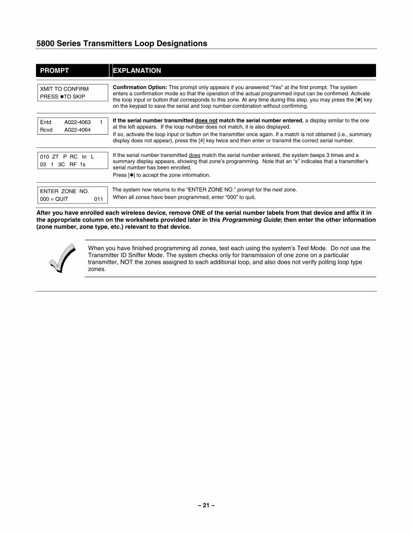
5800 Series Transmitters Loop Designations
PROMPT EXPLANATION
XMIT TO CONFIRM PRESS ✱TO SKIP
Confirmation Option: This prompt only appears if you answered “Yes” at the first prompt. The system enters a confirmation mode so that the operation of the actual programmed input can be confirmed. Activate the loop input or button that corresponds to this zone. At any time during this step, you may press the [✱] key on the keypad to save the serial and loop number combination without confirming.
Entd A022-4063 1 Rcvd A022-4064
If the serial number transmitted does not match the serial number entered, a display similar to the one at the left appears. If the loop number does not match, it is also displayed. If so, activate the loop input or button on the transmitter once again. If a match is not obtained (i.e., summary display does not appear), press the [#] key twice and then enter or transmit the correct serial number.
010 ZT P RC In L 03 1 3C RF 1s
If the serial number transmitted does match the serial number entered, the system beeps 3 times and a summary display appears, showing that zone’s programming. Note that an “s” indicates that a transmitter’s serial number has been enrolled. Press [✱] to accept the zone information.
ENTER ZONE NO. 000 = QUIT 011
The system now returns to the “ENTER ZONE NO.” prompt for the next zone. When all zones have been programmed, enter “000” to quit.
After you have enrolled each wireless device, remove ONE of the serial number labels from that device and affix it in the appropriate column on the worksheets provided later in this Programming Guide; then enter the other information (zone number, zone type, etc.) relevant to that device.
When you have finished programming all zones, test each using the system's Test Mode. Do not use the Transmitter ID Sniffer Mode. The system checks only for transmission of one zone on a particular transmitter, NOT the zones assigned to each additional loop, and also does not verify polling loop type zones.
– 22 –
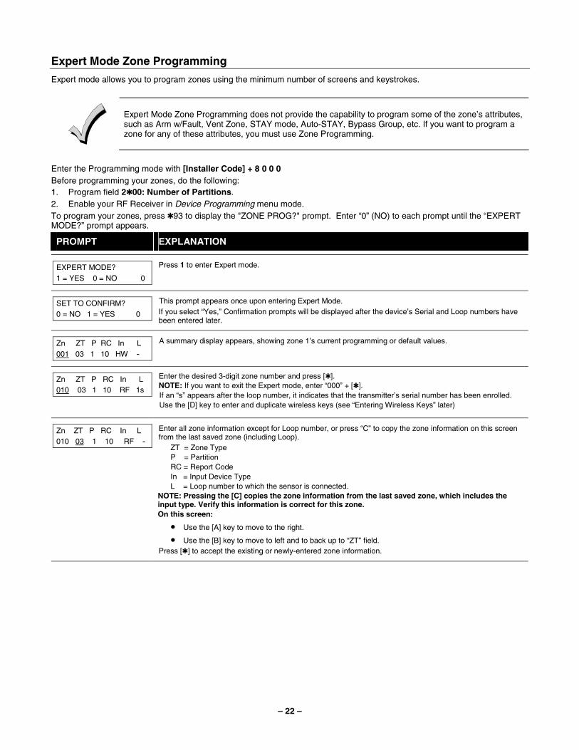
Expert Mode Zone Programming
Expert mode allows you to program zones using the minimum number of screens and keystrokes.
Expert Mode Zone Programming does not provide the capability to program some of the zone’s attributes, such as Arm w/Fault, Vent Zone, STAY mode, Auto-STAY, Bypass Group, etc. If you want to program a zone for any of these attributes, you must use Zone Programming.
Enter the Programming mode with [Installer Code] + 8 0 0 0 Before programming your zones, do the following: 1. Program field 2✱00: Number of Partitions. 2. Enable your RF Receiver in Device Programming menu mode. To program your zones, press ✱93 to display the "ZONE PROG?" prompt. Enter “0” (NO) to each prompt until the “EXPERT MODE?” prompt appears.
PROMPT EXPLANATION
EXPERT MODE? 1 = YES 0 = NO 0
Press 1 to enter Expert mode.
SET TO CONFIRM? 0 = NO 1 = YES 0
This prompt appears once upon entering Expert Mode. If you select “Yes,” Confirmation prompts will be displayed after the device’s Serial and Loop numbers have been entered later.
Zn ZT P RC In L 001 03 1 10 HW -
A summary display appears, showing zone 1’s current programming or default values.
Zn ZT P RC In L 010 03 1 10 RF 1s
Enter the desired 3-digit zone number and press [✱]. NOTE: If you want to exit the Expert mode, enter “000” + [✱]. If an “s” appears after the loop number, it indicates that the transmitter’s serial number has been enrolled. Use the [D] key to enter and duplicate wireless keys (see “Entering Wireless Keys” later)
Zn ZT P RC In L 010 03 1 10 RF -
Enter all zone information except for Loop number, or press “C” to copy the zone information on this screen from the last saved zone (including Loop).
ZT = Zone Type P = Partition RC = Report Code In = Input Device Type L = Loop number to which the sensor is connected.
NOTE: Pressing the [C] copies the zone information from the last saved zone, which includes the input type. Verify this information is correct for this zone. On this screen:
• Use the [A] key to move to the right.
• Use the [B] key to move to left and to back up to “ZT” field. Press [✱] to accept the existing or newly-entered zone information.
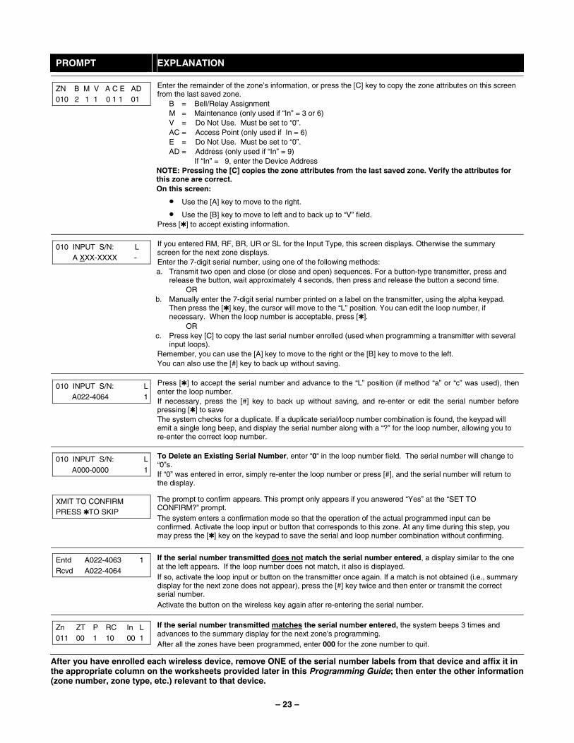
– 23 –
PROMPT EXPLANATION
ZN B M V A C E AD 010 2 1 1 0 1 1 01
Enter the remainder of the zone’s information, or press the [C] key to copy the zone attributes on this screen from the last saved zone.
B = Bell/Relay Assignment M = Maintenance (only used if “In” = 3 or 6) V = Do Not Use. Must be set to “0”. AC = Access Point (only used if In = 6) E = Do Not Use. Must be set to “0”. AD = Address (only used if “In” = 9)
If “In” = 9, enter the Device Address NOTE: Pressing the [C] copies the zone attributes from the last saved zone. Verify the attributes for this zone are correct. On this screen:
• Use the [A] key to move to the right.
• Use the [B] key to move to left and to back up to “V” field. Press [✱] to accept existing information.
010 INPUT S/N: L A XXX-XXXX -
If you entered RM, RF, BR, UR or SL for the Input Type, this screen displays. Otherwise the summary screen for the next zone displays. Enter the 7-digit serial number, using one of the following methods: a. Transmit two open and close (or close and open) sequences. For a button-type transmitter, press and
release the button, wait approximately 4 seconds, then press and release the button a second time. OR
b. Manually enter the 7-digit serial number printed on a label on the transmitter, using the alpha keypad. Then press the [✱] key, the cursor will move to the “L” position. You can edit the loop number, if necessary. When the loop number is acceptable, press [✱].
OR c. Press key [C] to copy the last serial number enrolled (used when programming a transmitter with several
input loops). Remember, you can use the [A] key to move to the right or the [B] key to move to the left. You can also use the [#] key to back up without saving.
010 INPUT S/N: L A022-4064 1
Press [✱] to accept the serial number and advance to the “L” position (if method “a” or “c” was used), then enter the loop number. If necessary, press the [#] key to back up without saving, and re-enter or edit the serial number before pressing [✱] to save The system checks for a duplicate. If a duplicate serial/loop number combination is found, the keypad will emit a single long beep, and display the serial number along with a “?” for the loop number, allowing you to re-enter the correct loop number.
010 INPUT S/N: L A000-0000 1
To Delete an Existing Serial Number, enter “0“ in the loop number field. The serial number will change to “0”s. If “0” was entered in error, simply re-enter the loop number or press [#], and the serial number will return to the display.
XMIT TO CONFIRM PRESS ✱TO SKIP
The prompt to confirm appears. This prompt only appears if you answered “Yes” at the “SET TO CONFIRM?” prompt. The system enters a confirmation mode so that the operation of the actual programmed input can be confirmed. Activate the loop input or button that corresponds to this zone. At any time during this step, you may press the [✱] key on the keypad to save the serial and loop number combination without confirming.
Entd A022-4063 1 Rcvd A022-4064
If the serial number transmitted does not match the serial number entered, a display similar to the one at the left appears. If the loop number does not match, it also is displayed. If so, activate the loop input or button on the transmitter once again. If a match is not obtained (i.e., summary display for the next zone does not appear), press the [#] key twice and then enter or transmit the correct serial number. Activate the button on the wireless key again after re-entering the serial number.
Zn ZT P RC In L 011 00 1 10 00 1
If the serial number transmitted matches the serial number entered, the system beeps 3 times and advances to the summary display for the next zone's programming. After all the zones have been programmed, enter 000 for the zone number to quit.
After you have enrolled each wireless device, remove ONE of the serial number labels from that device and affix it in the appropriate column on the worksheets provided later in this Programming Guide; then enter the other information (zone number, zone type, etc.) relevant to that device.
– 24 –
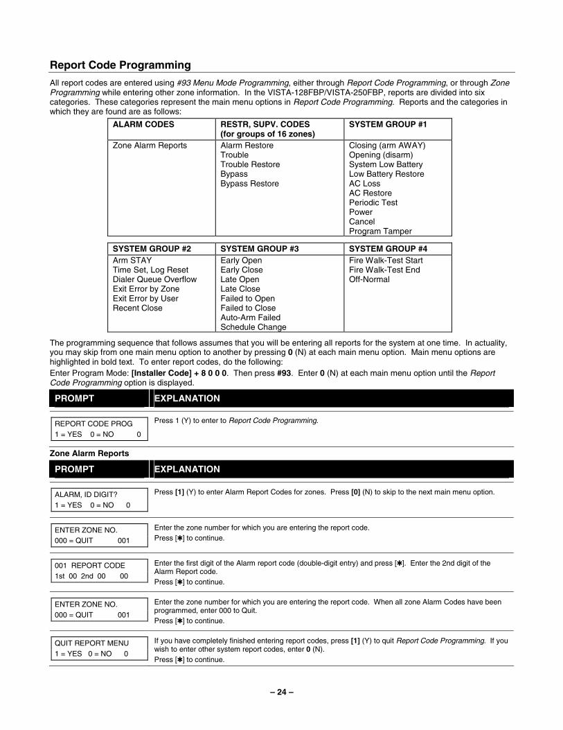
Report Code Programming
All report codes are entered using #93 Menu Mode Programming, either through Report Code Programming, or through Zone Programming while entering other zone information. In the VISTA-128FBP/VISTA-250FBP, reports are divided into six categories. These categories represent the main menu options in Report Code Programming. Reports and the categories in which they are found are as follows:
ALARM CODES RESTR, SUPV. CODES (for groups of 16 zones)
SYSTEM GROUP #1
Zone Alarm Reports Alarm Restore Trouble Trouble Restore Bypass Bypass Restore
Closing (arm AWAY) Opening (disarm) System Low Battery Low Battery Restore AC Loss AC Restore Periodic Test Power Cancel Program Tamper
SYSTEM GROUP #2 SYSTEM GROUP #3 SYSTEM GROUP #4 Arm STAY Time Set, Log Reset Dialer Queue Overflow Exit Error by Zone Exit Error by User Recent Close
Early Open Early Close Late Open Late Close Failed to Open Failed to Close Auto-Arm Failed Schedule Change
Fire Walk-Test Start Fire Walk-Test End Off-Normal
The programming sequence that follows assumes that you will be entering all reports for the system at one time. In actuality, you may skip from one main menu option to another by pressing 0 (N) at each main menu option. Main menu options are highlighted in bold text. To enter report codes, do the following: Enter Program Mode: [Installer Code] + 8 0 0 0. Then press #93. Enter 0 (N) at each main menu option until the Report Code Programming option is displayed.
PROMPT EXPLANATION
REPORT CODE PROG 1 = YES 0 = NO 0
Press 1 (Y) to enter to Report Code Programming.
Zone Alarm Reports
PROMPT EXPLANATION
ALARM, ID DIGIT? 1 = YES 0 = NO 0
Press [1] (Y) to enter Alarm Report Codes for zones. Press [0] (N) to skip to the next main menu option.
ENTER ZONE NO. 000 = QUIT 001
Enter the zone number for which you are entering the report code. Press [✱] to continue.
001 REPORT CODE 1st 00 2nd 00 00
Enter the first digit of the Alarm report code (double-digit entry) and press [✱]. Enter the 2nd digit of the Alarm Report code. Press [✱] to continue.
ENTER ZONE NO. 000 = QUIT 001
Enter the zone number for which you are entering the report code. When all zone Alarm Codes have been programmed, enter 000 to Quit. Press [✱] to continue.
QUIT REPORT MENU 1 = YES 0 = NO 0
If you have completely finished entering report codes, press [1] (Y) to quit Report Code Programming. If you wish to enter other system report codes, enter 0 (N). Press [✱] to continue.

– 25 –
Restore/Supervisory Codes
PROMPT EXPLANATION
RESTR, SUPV. CODE 1 = YES 0 = NO 0
Press [1] (Y) to enter Restore and Supervisory Codes for zones.
ENTER ZN FOR GRP 000 = QUIT 001
Enter one zone for each group of 16 zones (001-016, 017-032, etc.).
ALARM RESTORE GRP 001-016 00
Enter the first digit of the Alarm Restore Report Code for this group of zones (double-digit entry). The second digit (for two-digit reporting formats) is automatically the ID (second) digit of the Alarm Report Code for each zone (if programmed). Press [✱] to continue.
TROUBLE GRP 001-016 00
Enter the first digit of the Trouble Report Code for this group of zones (double-digit entry). The second digit (for two-digit reporting formats) is automatically the ID (second) digit of the Alarm Report Code for each zone (if programmed). Press [✱] to continue.
TROUBLE RESTORE GRP 001-016 00
Enter the first digit of the trouble restore code (single-digit entry) and press [✱]. The second digit (for two-digit reporting formats) is automatically the ID (second) digit of the alarm report code for each zone (if programmed). Press [✱] to continue.
BYPASS GRP 001-016 00
Enter the first digit of the Bypass Report Code (double-digit entry) and press [✱]. The second digit (for two-digit reporting formats) is automatically the ID (second) digit of the Alarm Report Code for each zone (if programmed). Press [✱] to continue.
BYPASS RESTORE GRP 001-016 00
Enter the first digit of the Bypass Restore Report Code (double-digit entry) and press [✱]. The second digit (for two-digit reporting formats) is automatically the ID (second) digit of the Alarm Report Code for each zone (if programmed). Press [✱] to continue.
ENTER ZN FOR GRP 000 = QUIT 017
Enter one zone for each group of 16 zones. When you are finished entering Restore and Supervisory Codes for all zone groups, enter 000. Press [✱] to continue.
QUIT REPORT MENU 1 = YES 0 = NO 0
If you have completely finished entering report codes, press [1] (Y) to quit Report Code Programming. If you wish to enter other system report codes, enter 0 (N). Press [✱] to continue.
System Group #1 Codes
PROMPT EXPLANATION
SYSTEM GROUP #1? 1 = YES 0 = NO 0
To enter System Group #1 codes, press 1 (Y).
CLOSE 1st 00 2nd 00
Enter the first digit of the Closing (Arm-AWAY) report. Press [✱]. Enter the second digit of the report. If the user number is desired as the second digit, enter 01 (not necessary for Contact ID or High Speed formats). Press [✱] to continue.
– 26 –
PROMPT EXPLANATION
Enter the rest of the codes in the same manner. Other report codes in System Group #1 are:
• Opening (Disarm) Also, enable this if you desire Callback Requested reports (the panel answers a phone call from the downloader).
• System Low Battery
• Low Battery Restore
• AC Loss
• AC Restore
• Periodic Test
• Power
• Cancel
• Program Tamper Once you have entered these report codes, the system prompts you with the Quit menu.
QUIT REPORT MENU 1 = YES 0 = NO 0
If you have completely finished entering report codes, press 1 (Y) to quit Report Code Programming. If you wish to enter other system report codes, enter 0 (N). Press [✱] to continue.
System Group #2 Codes
PROMPT EXPLANATION
SYSTEM GROUP #2 ? 1 = YES 0 = NO 0
To enter System Group #2 codes, press [1] (Y).
STAY 1st 00 2nd 00
Enter the first digit of the Arm-STAY report. Press [✱]. Enter the second digit of the report. If the user number is desired as the second digit, enter 01 (not necessary for Contact ID or High Speed formats). Press [✱] to continue.
Enter the rest of the codes in the same manner. Other codes in System Group #2 are:
• Time Set, Log Reset
• Dialer Queue Overflow
• Exit Error by Zone
• Exit Error by User
• Recent Close Once you have entered these report codes, the system prompts you with the Quit menu.
QUIT REPORT MENU 1 = YES 0 = NO 0
If you have completely finished entering report codes, press [1] (Y) to quit Report Code Programming. If you wish to enter other system report codes, enter 0 (N). Press [✱] to continue.
System Group #3 Codes
PROMPT EXPLANATION
SYSTEM GROUP #3 ? 1 = YES 0 = NO 0
To enter System Group #3 codes, press [1] (Y).
EARLY OPEN 1st 00 2nd 00
Enter the first digit of the Early Opening Report Code. Press [✱]. Enter the second digit of the report code. If the user number is desired as the second digit, enter 01 (not necessary for Contact ID or High Speed formats). Press [✱] to continue.
– 27 –
PROMPT EXPLANATION
Enter the rest of the codes in the same manner. Other codes in System Group #3 are:
• Early Close
• Late Open
• Late Close
• Failed to Open
• Failed to Close
• Auto-Arm Failed
• Schedule Change Once you have entered these report codes, the system prompts you with the Quit menu.
QUIT REPORT MENU 1 = YES 0 = NO 0
If you have completely finished entering report codes, press [1] (Y) to quit Report Code Programming. If you wish to enter other system report codes, enter 0 (N) Press [✱] to continue.
System Group #4 Codes
PROMPT EXPLANATION
SYSTEM GROUP #4 ? 1 = YES 0 = NO 0
To enter System Group #4 codes, press [1] (YES).
WALK TEST START 1st 00 2nd 00
Enter the first digit of the Fire Walk Test Start Report Code. Press [✱]. Enter the second digit of the report code. Press [✱] to continue.
Enter the rest of the codes in the same manner. Other codes in System Group #4 are:
• Fire Walk-Test End.
• Off-Normal. Once you have entered these report codes, the system prompts you with the Quit menu.
QUIT MENU MODE? 1 = YES 0 = NO 0
Enter 1 to exit back to normal Programming mode. Enter 0 to stay in Menu mode.
– 28 –
Alpha Descriptors Programming You can program a user-friendly English language description/location for all protection zones, relays, keypad panics, polling loop short, and RF receiver supervision troubles. Each description can be composed of a combination of words (up to 3) that are selected from a vocabulary of 244 words stored in memory, and any word can have an "s" or " 's " added to it. NOTE: Due to the use of 3-digit zone numbers, the first word of the descriptor is limited to 6 characters if you want it to fit on the top line of the display. In addition, up to 60 installer-defined words can be added to those already in memory. Thus, when an alarm or trouble occurs in a zone, an appropriate description for the location of that zone will be displayed at the keypad. A custom installer's message can be programmed for each partition which is displayed when the system is "Ready" (e.g., THE PETERSONS’). 1. To program alpha descriptors, enter Programming mode, then press #93 to display "ZONE PROG?" 2. Press [0] (NO) twice to display "ALPHA PROG?". 3. Press [1] to enter Alpha Programming.
There are 6 submenu selections that will be displayed one at a time. Press [1] to select the mode desired. Press [0] to display the next mode available. The alpha menu selections are:
ZONE DESCRIP? For entering zone descriptors.
DEFAULT SCREEN? For creating custom message; displayed when system is ready.
CUSTOM WORD? For creating custom words for use in descriptors.
PART DESCRIP? For creating 4-character partition names.
EXIT EDIT MODE? Press [1] to exit back to #93 Menu Mode.
4. Refer to the sections that follow for procedures for adding alpha descriptors.
Zone Descriptors 1. Select ZONE DESCRIPTOR mode.
The keypad keys perform the following functions: [3] Scrolls both alphabet and actual words in ascending alphabetical order. [1] Scrolls both alphabet and actual words in descending alphabetical order. [2] Adds or removes an "s" or " 's " to a vocabulary word. [6] Switches between alphabet and actual word list; used to accept entries. [8] Saves the zone description in the system's memory. [#] [#] plus zone number displays the description for that zone.
2. Enter the zone number to which you want to assign a descriptor. For example, key [✱] 001 to begin entering the description for Zone 1, (key [✱] 002 for Zone 2, [✱] 003 for Zone 3, etc.). The following is displayed: ✱ ZN 001 A. Note that the first letter of the alphabet appears after the zone number, and that the zone number is automatically included with the description.
3. Enter the descriptor for that zone. Use one of two methods as follows: (Assume, for example, that the desired description for Zone 1 is BACK DOOR.) a) Press [#] followed by the 3-digit number of the first word from the fixed dictionary shown later in this section (e.g.,
[0][1][3] for BACK). Press [6] in order to accept the word and proceed, or press [8] to store the complete descriptor and exit;
or b) Select the first letter of the desired description (note that "A" is already displayed). Use the [3] key to advance
through the alphabet and the [1] key to go backward. Press [3] key repeatedly until "B" appears (press [1] to go backwards if you happen to pass it), then press [6] to display the first available word beginning with “B”. Press [3] repeatedly to advance through the available words until the word “BACK” is displayed.
To add an "s" or " 's," if you need to, press 2. The first depression adds an "s," the second depression adds an " 's, " the third depression displays no character (to erase the character), the fourth depression adds an "s," etc.
– 29 –
4. Accept the word.
To accept the word, press [6], which switches back to the alphabet list for the next word, or press [8] to store the complete descriptor and then exit.
5. Select the next word. For selection of the next word (DOOR), repeat step 3a (word #057) or 3b, but selecting the word "DOOR.” To accept the word, press [6], which again switches back to alphabet list.
6. Store the descriptor. When all desired words have been entered, press [8] to store the description in memory. To review the zone descriptors, key [#] plus zone number (e.g., #001). To edit zone descriptors, key [✱] plus zone number (e.g., ✱001)
7. Exit Zone Description Mode: enter 000.
Default Screen (Custom Message Display) Normally, when the system is in the disarmed state, the following display is present on the keypad.
****DISARMED**** READY TO ARM
Part or the entire above message can be modified to create a custom installer message for each partition. For example, “****DISARMED****” on the first line or “READY TO ARM” on the second line could be replaced by the installation company name or phone number for service. NOTE: There are only 16 character spaces on each of the two lines. To create a custom display message, proceed as follows: 1. Select Default Screen mode.
The keypad asks for the partition number for this message. Enter the partition number. Press [✱] to accept entry. The following display appears:
****DISARMED**** READY TO ARM
A cursor is present at the extreme left of the first line (over the first "star"). Press [6] to move the cursor to the right and [4] to move the cursor to the left. Press [7] to insert spaces or erase existing characters.
2. Create the message. For example, to replace “READY TO ARM” with the message “SERVICE 424-0177,” proceed as follows: Press [6] to move the cursor to the right, and continue until the cursor is positioned over the first location on the second line. Press [3] to advance through the alphabet to the first desired character (in this case, "S"). Press [1] to go backward, when necessary. When the desired character is reached, press [6]. The cursor then moves to the next position, ready for entry of the next character (in this example, "E"). When the cursor reaches a position over an existing character, press [3] or [1] to advance or back up from that character in the alphabet. Proceed in this manner until all characters in the message have been entered.
3. Save the message. Store the new display message in memory by pressing [8].
4. The system asks for a new partition number. Enter 0 to quit or 1-8 for a new partition number.
Custom Words Up to 60 installer-defined words can be added to the built-in vocabulary. Each of the 60 "words" can actually consist of several words, but bear in mind that a maximum of 10 characters can be used for each word string. 1. Select CUSTOM WORD Mode.
The keys perform the following functions: [3] Advances through alphabet in ascending order. [1] Advances through alphabet in descending order. [6] Selects desired letter; moves the cursor 1 space to the right. [4] Moves the cursor one space to the left. [7] Inserts a space at the cursor location, erasing any character at that location. [8] Saves the new word in the system's memory. [✱] Returns to Description Entry Mode.
2. Enter the custom word number (01-60) you want to create. For example, if you are creating the first word (or word string), enter 01; when creating the second word, enter 02, and so on. A cursor now appears at the beginning of the second line.
– 30 –
3. Type the word using one of two methods as follows: a) Press [#], followed by the 2-digit entry for the first letter you would like to display (e.g., 65 for "A").
When the desired character appears, press [6] to select it. The cursor will then move to the right, in position for the next character. Press [#] plus the 2-digit entry for the next letter of the word.
or b) Press 3 to advance through the list of symbols, numbers, and letters.
Press 1 to move back through the list. When you have reached the desired character, press [6] to select it. The cursor then moves to the right, in position for the next character.
4. Repeat step 3 to create the desired custom word (or words). Press [4] to move the cursor to the left if necessary. Press [7] to enter a blank (or to erase an existing character). Each word or word string cannot exceed 10 characters.
5. Save the word by pressing [8]. This returns you to the “CUSTOM WORD?” display. The custom word (or string of words) is automatically added to the built-in vocabulary at the end of the group of words beginning with the same letter. Custom words are retrieved as word numbers 255 to 314 for words 1 to 60, respectively, when using method 3a to enter alpha descriptors. When using method 3b to enter alpha descriptors, each word appears at the end of the group of words that begin with the same letter as it does.
6. Repeat steps 2 through 6 to create up to a maximum of 60 custom words (or word strings). 7. Exit Custom Word Mode by entering 00 at the “CUSTOM WORD” prompt.
Partition Descriptors 1. Select "Part DESCRIPT." Mode.
The system asks for the partition number desired. Enter the number as a single-key entry 1-8. 2. Follow the same procedure as for custom words.
NOTE: The partition descriptors are limited to 4 characters (e.g., WHSE for warehouse).
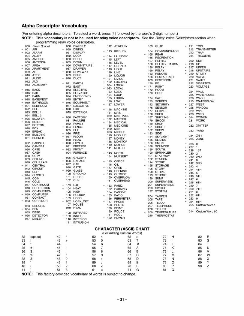
– 31 –
Alpha Descriptor Vocabulary
(For entering alpha descriptors. To select a word, press [#] followed by the word's 3-digit number.) NOTE: This vocabulary is not to be used for relay voice descriptors. See the Relay Voice Descriptors section when
programming relay voice descriptors. 000 (Word Space) • 001 AIR • 002 ALARM 004 ALLEY 005 AMBUSH 006 ANTENNA • 007 AREA • 008 APARTMENT 009 ART • 010 ATTIC 011 AUDIO 012 AUX 013 AUXILIARY
• 015 BACK • 016 BAR 017 BARN • 018 BASEMENT • 019 BATHROOM • 021 BEDROOM 022 BELL 023 BELL 1 024 BELL 2 • 025 BLOWER • 026 BOILER 027 BOTTOM 028 BOX 029 BREAK • 030 BUILDING 031 BURNER
032 CABINET 034 CAMERA 036 CASE 037 CASH 038 CCTV 039 CEILING 040 CELLULAR • 041 CENTRAL 042 CIRCUIT 043 CLIP • 044 CLOSED 045 COIN 046 COLD 047 COATROOM 048 COLLECTION 049 COMBUSTION • 050 COMPUTER 051 CONTACT • 033 CORRIDOR
053 DELAYED • 054 DEN 055 DESK • 056 DETECTOR 057 DIALER 1
058 DIALER 2 • 059 DINING 061 DISPLAY 062 DOCK • 063 DOOR • 065 DOWN • 066 DOWNSTAIRS 067 DRAWER • 068 DRIVEWAY 069 DRUG • 070 DUCT
• 071 EARTH 072 EAST 073 ELECTRIC 035 ELEVATOR 074 EMERGENCY 075 ENTRY • 076 EQUIPMENT 077 EXECUTIVE • 078 EXIT 079 EXTERIOR
• 080 FACTORY 081 FAILURE 082 FAMILY • 084 FENCE 085 FILE • 086 FIRE • 087 FLOOR 088 FLOW • 090 FOYER 091 FREEZER • 092 FRONT 094 FURNACE
095 GALLERY • 096 GARAGE • 097 GAS 098 GATE • 099 GLASS 100 GROUND 101 GUEST 102 GUN
• 103 HALL • 104 HEAT 105 HIGH 106 HOLDUP • 139 HOOD • 052 HORN_CKT 107 HOUSE 060 HVAC
108 INFRARED • 109 INSIDE 110 INTERIOR 111 INTRUSION
112 JEWELRY
• 113 KITCHEN
• 114 LAUNDRY • 115 LEFT 116 LEVEL • 117 LIBRARY • 118 LIGHT 119 LINE 120 LIQUOR • 121 LIVING • 122 LOADING 064 LOBBY • 083 LOCAL 123 LOCK 124 LOOP 125 LORRA 126 LOW • 127 LOWER
• 128 MACHINE 131 MAIN 089 MAN_PULL • 132 MASTER • 134 MEDICAL 135 MEDICINE • 020 MEN 093 MIDDLE 129 MODULE 137 MONEY 138 MONITOR • 140 MOTION 141 MOTOR
• 143 NORTH 144 NURSERY
• 145 OFFICE 146 OIL • 147 OPEN 148 OPENING • 149 OUTSIDE 150 OVERFLOW 151 OVERHEAD
• 153 PANIC 152 PARKING 154 PASSIVE • 155 PATIO 156 PERIMETER • 157 PHONE 158 PHOTO 159 POINT 160 POLICE 161 POOL • 162 POWER
163 QUAD
164 COMMUNICATOR • 165 REAR 166 RECREATION 167 REFRIG 168 REFRIGERATION 130 RELAY 169 RELAY 1 133 REMOTE 136 RESTAURANT 003 RESTROOM 170 RF • 171 RIGHT • 172 ROOM 173 ROOF
174 SAFE 175 SCREEN 142 SECURITY 176 SENSOR • 177 SERVICE • 178 SHED 187 SHIPPING 179 SHOCK • 180 SHOP 181 SHORT 182 SHOW • 183 SIDE 184 SKYLIGHT 185 SLIDING • 186 SMOKE • 188 SOUNDER • 189 SOUTH 190 SPRINKLER 191 STAIRWAY • 192 STATION 194 STORE • 195 STORAGE 196 STORY 198 STRIKE 193 STROBE 199 SUMP 200 SUPERVISED 201 SUPERVISION 203 SWITCH 197 SYSTEM
204 TAMPER 205 TAPE 206 TELCO 207 TELEPHONE 208 TELLER • 209 TEMPERATURE 210 THERMOSTAT
• 211 TOOL 212 TRANSMITTER 213 TRAP 214 TRIGGERS
202 UNIT • 216 UP • 217 UPPER • 218 UPSTAIRS • 219 UTILITY 220 VALVE 221 VAULT 222 VIBRATION 223 VOLTAGE
224 WALL 225 WAREHOUSE 226 WASH 215 WATERFLOW • 227 WEST • 228 WINDOW 229 WINE • 230 WING • 014 WOMEN 231 WORK
232 XMITTER
233 YARD
234 ZN-1 • 235 ZONE
• 236 0 • 237 1 • 238 1ST • 239 2 • 240 2ND • 241 3 • 242 3RD • 243 4 • 244 4TH • 245 5 • 246 5TH • 247 6 • 248 6TH • 249 7 • 250 7TH • 251 8 • 252 8TH • 253 9 • 254 9TH 255 Custom Word 1 to 314 Custom Word 60
CHARACTER (ASCII) CHART (For Adding Custom Words)
32 (space) 33 ! 34 " 35 # 36 $ 37 % 38 & 39 ' 40 ( 41 )
42 * 43 + 44 , 45 - 46 . 47 / 48 0 49 1 50 2 51 3
52 4 53 5 54 6 55 7 56 8 57 9 58 : 59 ; 60 < 61 =
62 > 63 ? 64 @ 65 A 66 B 67 C 68 D 69 E 70 F 71 G
72 H 73 I 74 J 75 K 76 L 77 M 78 N 79 O 80 P 81 Q
82 R 83 S 84 T 85 U 86 V 87 W 88 X 89 Y 90 Z
NOTE: This factory-provided vocabulary of words is subject to change.
– 32 –
Device Programming
This menu is used to program keypads, receivers, and relay modules, etc.
Device Address 00 is always set as an alpha keypad assigned to Partition 1 with no sounder suppression options, and these settings cannot be changed.
From Data Field Programming mode, press #93 to display "ZONE PROG?" Press [0] repeatedly to display "DEVICE PROG?"
PROMPT EXPLANATION
DEVICE PROG? 1=YES 0=NO 0
Press [1] to enter Device Programming.
DEVICE ADDRESS 01-30, 00=QUIT 01
The device address identifies the device to the control. Enter the 2-digit device address number to match the device's physical address setting (01-30). Press [✱] to accept entry.
Select the type of addressable device as follows:
00 = device not used 05 = Do Not Use
01 = alpha keypad (6160/6160CR-2) 06 = communicator 03 = RF receiver (5881) 09 = Do Not Use
04 = output relay module (4204) 10 = Do Not Use
DEVICE TYPE 00
Press [✱] to accept entry.
Alpha Keypad
PROMPT EXPLANATION
01 CONSOLE PART. 1
If you selected device type 01 (alpha keypad), this prompt appears. Enter the addressable device's default partition number (01 to maximum number of partitions programmed for system in field 2*00). This is the primary partition for the device. Enter 9 to make this keypad a "Master" keypad for the system. Press [✱] to accept entry.
01 SOUND OPTION 00
If you entered device type 01 (alpha keypad), this prompt appears. Keypads can be individually programmed to suppress arm/disarm beeps, entry/exit beeps and chime mode beeps. This helps prevent unwanted sounds from disturbing users in other areas of the premises. Enter a number 00-03 for the keypad sounding suppression options desired for the keypad as follows:
00 = no suppression 01 = suppress arm/disarm & entry/exit beeps 02 = suppress chime mode beeps only 03 = suppress arm/disarm, entry/exit and chime mode beeps
Press [✱] to accept entry.
01 KEYPAD GLBL? 0
If you entered device type 01 (alpha keypad), this prompt appears. Each keypad can give users with access to multiple partitions the ability to arm and disarm those partitions from it. To enable this keypad for global arming/disarming, enter 1. To prevent the ability to use this keypad for global arming/disarming, enter 0. Press [✱] to accept entry.
01 AUI ? 1 = YES 0 = NO 0
Do Not Use. Must be set to “0”.
Press [✱] to accept entry.
– 33 –
RF Expander
PROMPT EXPLANATION
01 RF EXPANDER HOUSE ID 00
If you selected device type 03 (RF receiver), this prompt appears. Enter the 2-digit House ID (00-31). Press [✱] to accept entry.
Output Relay Module
PROMPT EXPLANATION
01 SUPERVISED CF? 0
If you selected device type 04 (relay module), this prompt appears. Enter 1 if the unit is a 4204CF. If not, enter 0. If you enter 1, only Relay 1 (Output A) and Relay 3 (Output B) on each module may be programmed for functions. NOTE: For Commercial Fire installations, only one notification appliance module may be used, and only one notification appliance output (A or B) may be used on that module. Press [✱] to accept entry.
Communicator If you selected device type 6, the 6160/6160CR-2 Keypad functions similarly to the 7720P Programming Tool. See Figure 1 for the functions of the keys on the 6160CR-2.
1 OFF
4 MAX
7 INSTANT
READY
2 AWAY
5 TEST
8 CODE
0
3 STAY
6 BYPASS
9 CHIME
#
SILENCED
TROUBLE
ALARM
SUPV
POWER
6160
CR
2-00
1-V0
ARMED
READY
Figure 1: 6160CR-2 Key Functions for Programming the Communicator
Each key has two possible functions: a normal function and a SHIFT function. To perform a normal key function, simply press the desired key. To perform a SHIFT key function, press SHIFT key, then press desired function key. Normal and SHIFT key Functions:
Key Normal Key Function SHIFT Key Function BS/ESC [BS]: Press to delete entry [ESC]: Press to quit Program Mode Also, can reset EEPROM defaults * ↓/↑ [↓]: Scroll down programming [↑]: Scroll up programming N/Y [N]: Press for "NO" answer [Y]: Press SHIFT-Y for "YES" answer SHIFT
Press before pressing a SHIFT key function. Will light READY LED. LED goes out once a key is pressed. Press again for each SHIFT function desired.
1/A [1]: For entering the number 1 [A]: Used for entering C.S. ID number 2/B [2]: For entering the number 2 [B]: Used for entering C.S. ID number 3/C [3]: For entering the number 3 [C]: Used for entering C.S. ID number 4/D [4]: For entering the number 4 [D]: Used for entering C.S. ID number 5/E [5]: For entering the number 5 [E]: Used for entering C.S. ID number 6/F [6]: For entering the number 6 [F]: Used for C.S. ID & FAST Mode 7/S [7]: For entering the number 7 [S]: Press to display diagnostic status 8/T [8]: For entering the number 8 [T]: Press to send TEST messages 9/X [9]: For entering the number 9 [X]: Press to reset the 7845i-ent */SPACE [*]: Not used with 7845i-ent [SPACE]: Not used with 7845i-ent 0 [0]: For entering the number 0 No SHIFT function #/ENTER [#/ENTER]: Press to accept entries No SHIFT function
* Active only when the "REVIEW?" prompt is displayed.
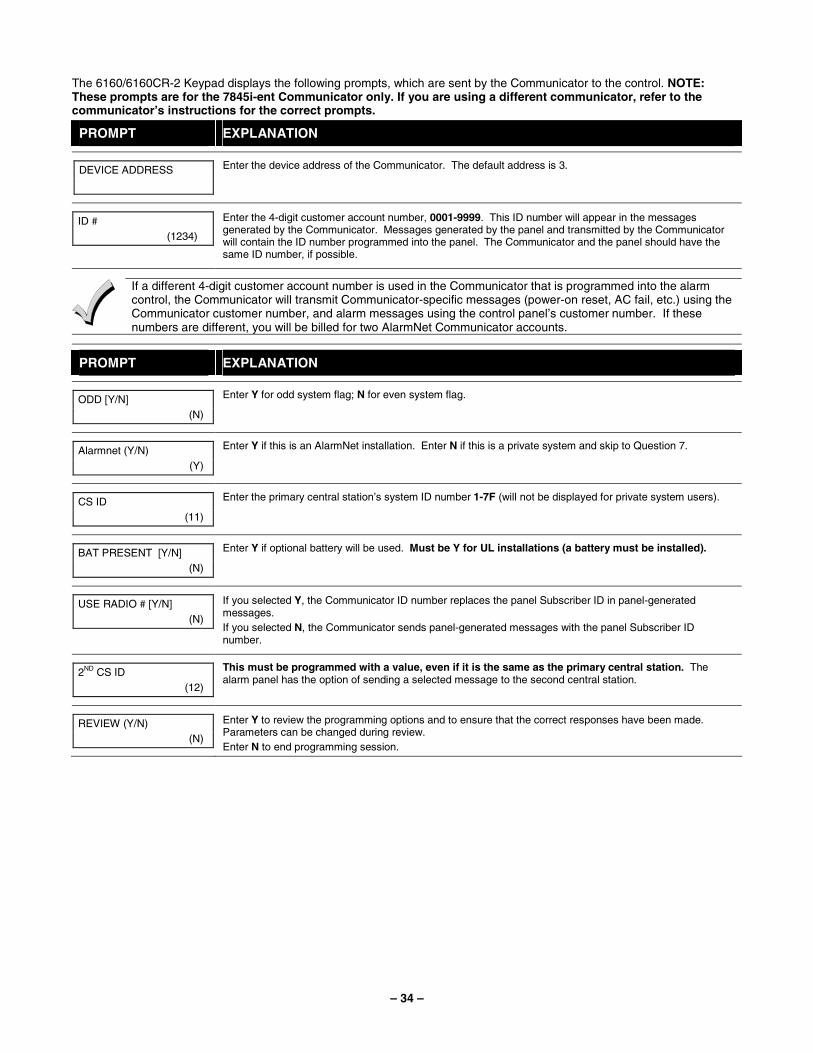
– 34 –
The 6160/6160CR-2 Keypad displays the following prompts, which are sent by the Communicator to the control. NOTE: These prompts are for the 7845i-ent Communicator only. If you are using a different communicator, refer to the communicator’s instructions for the correct prompts.
PROMPT EXPLANATION
DEVICE ADDRESS
Enter the device address of the Communicator. The default address is 3.
ID # (1234)
Enter the 4-digit customer account number, 0001-9999. This ID number will appear in the messages generated by the Communicator. Messages generated by the panel and transmitted by the Communicator will contain the ID number programmed into the panel. The Communicator and the panel should have the same ID number, if possible.
If a different 4-digit customer account number is used in the Communicator that is programmed into the alarm control, the Communicator will transmit Communicator-specific messages (power-on reset, AC fail, etc.) using the Communicator customer number, and alarm messages using the control panel’s customer number. If these numbers are different, you will be billed for two AlarmNet Communicator accounts.
PROMPT EXPLANATION
ODD [Y/N] (N)
Enter Y for odd system flag; N for even system flag.
Alarmnet (Y/N) (Y)
Enter Y if this is an AlarmNet installation. Enter N if this is a private system and skip to Question 7.
CS ID (11)
Enter the primary central station’s system ID number 1-7F (will not be displayed for private system users).
BAT PRESENT [Y/N] (N)
Enter Y if optional battery will be used. Must be Y for UL installations (a battery must be installed).
USE RADIO # [Y/N] (N)
If you selected Y, the Communicator ID number replaces the panel Subscriber ID in panel-generated messages. If you selected N, the Communicator sends panel-generated messages with the panel Subscriber ID number.
2ND CS ID (12)
This must be programmed with a value, even if it is the same as the primary central station. The alarm panel has the option of sending a selected message to the second central station.
REVIEW (Y/N) (N)
Enter Y to review the programming options and to ensure that the correct responses have been made. Parameters can be changed during review. Enter N to end programming session.
– 35 –
Output Programming
The system supports up to 96 outputs. Outputs can be used to perform many different functions and actions. Each output must be programmed to begin one of four types of ACTIONS at a designated START event, and end that ACTION at a designated STOP event. The options used to start and stop these devices are described below, followed by the actual screen prompts and available entries. NOTE: If you are using outputs on the polling loop (e.g., 4101SN) no more than 20 of the polling loop outputs may be programmed for the same START or STOP condition. Also, if you are using ZONE # for the START of a polling loop output and want that output to stop when the same zone restores, the STOP programming MUST BE BLANK. The letter(s) in parentheses after each function described below, such as (A) after ACTION, are those that appear in the various summary displays of programmed data during programming. ACTION (A) The "ACTION" of the device is how the device will respond when it is activated by the "START"
programming. You may want the device to activate momentarily, to pulse on and off continuously, or to remain activated until some other event occurs to stop it. There are five different action choices:
• ACTIVATE for 2 SECONDS and then reset. If selected, it is not necessary to program a stop parameter.
• ACTIVATE and REMAIN ACTIVATED until stopped by some other event. • PULSE ON and OFF until stopped by some other event. • NO RESPONSE when the device is not used. • TOGGLE on and off alternately with each activation of event. Do not program a stop parameter as
this may cause unpredictable results. START (STT) The "START" programming determines when and under what conditions the device is activated. The
following START options are available: 1) EVENT (EV) is the condition (alarm, fault, trouble) that must occur to a zone or group of zones (zone
list) in order to activate the device. These conditions apply only when a zone list is used. The different choices for "EVENT" are listed below and in “Programming Relays” later in this section. • ALARM Action begins upon any alarm in an assigned zone in the zone list. • FAULT Action begins upon any opening of an assigned zone in the zone list. • TROUBLE Action begins upon any trouble condition in an assigned zone in the zone list. • NOT USED Action is not dependent upon one of the above events. ZONE LIST (ZL) is a group of zones to which the “EVENT” applies in order to activate a particular device. Note that there are a total of 15 zone lists that can be programmed; when the selected EVENT (alarm, fault or trouble) occurs in any zone in the selected “Start” ZONE LIST (01-15), activation of the selected device will START.
2) ZONE # A specific zone going into alarm, fault, trouble, or restore (Event programming) can be used to start the relay action. Enter the 3-digit zone number (000-250).
3) ZONE TYPE/SYSTEM OPERATION (ZT). If all zones to be used to start the device have the same response type, and there are no other zones of this type that are not to activate this device, then “ZONE TYPE” may be used instead of a "ZONE LIST" and "EVENT” to activate the device. If a system operation, such as “DISARMING” or “ANY FIRE ALARM,” is to activate the device, enter the appropriate choice under the “ZONE TYPE” option. The “ZONE TYPE/SYSTEM OPERATION” option functions independently of the “EVENT/ZONE LIST” combination. If a specific "ZONE TYPE" is chosen, any zone of that response type going into alarm, trouble, or fault will cause the device to activate as selected in "ACTION.” If the same “ZONE TYPE” is also chosen for the STOP programming, any zone of that type that restores will de-activate the device. If a "SYSTEM OPERATION" is chosen, that operation will cause the device to activate as selected in "ACTION.” The different choices for "ZONE TYPE" and "SYSTEM OPERATION" are listed in “Programming Relays” later in this section, and on the Programming Form.
4) PARTITION NO. (P). The device's "Start" ZONE TYPE/SYSTEM OPERATION may be limited to an occurrence on one partition (1-8), or any partition (0).
STOP (STP): The "STOP" programming determines when and under what conditions the device is de-activated. The following options are available: 1). RESTORE ZONE LIST (ZL). If a "ZONE LIST" is used as the “Stop” event, the device de-activates
when all the zones in that list restore from a previous fault, trouble, or alarm condition. This occurs regardless of what is programmed to "START" the device; therefore, a "RESTORE ZONE LIST" is normally only used when a "ZONE LIST" is used to start the device.
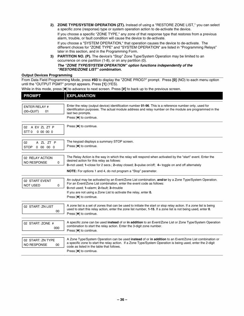
– 36 –
2). ZONE TYPE/SYSTEM OPERATION (ZT). Instead of using a "RESTORE ZONE LIST," you can select a specific zone (response) type or system operation action to de-activate the device. If you choose a specific "ZONE TYPE," any zone of that response type that restores from a previous alarm, trouble, or fault condition will cause the device to de-activate. If you choose a "SYSTEM OPERATION," that operation causes the device to de-activate. The different choices for "ZONE TYPE" and "SYSTEM OPERATION" are listed in “Programming Relays” later in this section, and in the Programming Form.
3) PARTITION NO. (P). The device's "Stop" Zone Type/System Operation may be limited to an occurrence on one partition (1-8), or on any partition (0). The “ZONE TYPE/SYSTEM OPERATION” option functions independently of the “RESTORE/ZONE LIST” combination.
Output Devices Programming From Data Field Programming Mode, press #93 to display the "ZONE PROG?" prompt. Press [0] (NO) to each menu option until the "OUTPUT PGM?" prompt appears. Press [1] (YES). While in this mode, press [✱] to advance to next screen. Press [#] to back up to the previous screen.
PROMPT EXPLANATION
ENTER RELAY # (00=QUIT) 01
Enter the relay (output device) identification number 01-96. This is a reference number only, used for identification purposes. The actual module address and relay number on the module are programmed in the last two prompts. Press [✱] to continue.
02 A EV ZL ZT P STT 0 0 00 00 0
Press [✱] to continue.
02 A ZL ZT P STOP 0 00 00 0
The keypad displays a summary STOP screen. Press [✱] to continue.
02 RELAY ACTION NO RESPONSE 0
The Relay Action is the way in which the relay will respond when activated by the "start" event. Enter the desired action for this relay as follows: 0=not used; 1=close for 2 secs.; 2=stay closed; 3=pulse on/off; 4= toggle on and off alternately
NOTE: For options 1 and 4, do not program a “Stop” parameter.
02 START EVENT NOT USED 0
An output may be activated by an Event/Zone List combination, and/or by a Zone Type/System Operation. For an Event/Zone List combination, enter the event code as follows: 0=not used; 1=alarm; 2=fault; 3=trouble If you are not using a Zone List to activate the relay, enter 0. Press [✱] to continue.
02 START: ZN LIST 00
A zone list is a set of zones that can be used to initiate the start or stop relay action. If a zone list is being used to start this relay action, enter the zone list number, 1-15. If a zone list is not being used, enter 0. Press [✱] to continue.
02 START: ZONE # 000
A specific zone can be used instead of or in addition to an Event/Zone List or Zone Type/System Operation combination to start the relay action. Enter the 3-digit zone number. Press [✱] to continue.
02 START: ZN TYPE NO RESPONSE 00
A Zone Type/System Operation can be used instead of or in addition to an Event/Zone List combination or a specific zone to start the relay action. If a Zone Type/System Operation is being used, enter the 2-digit code as listed in the table that follows. Press [✱] to continue.
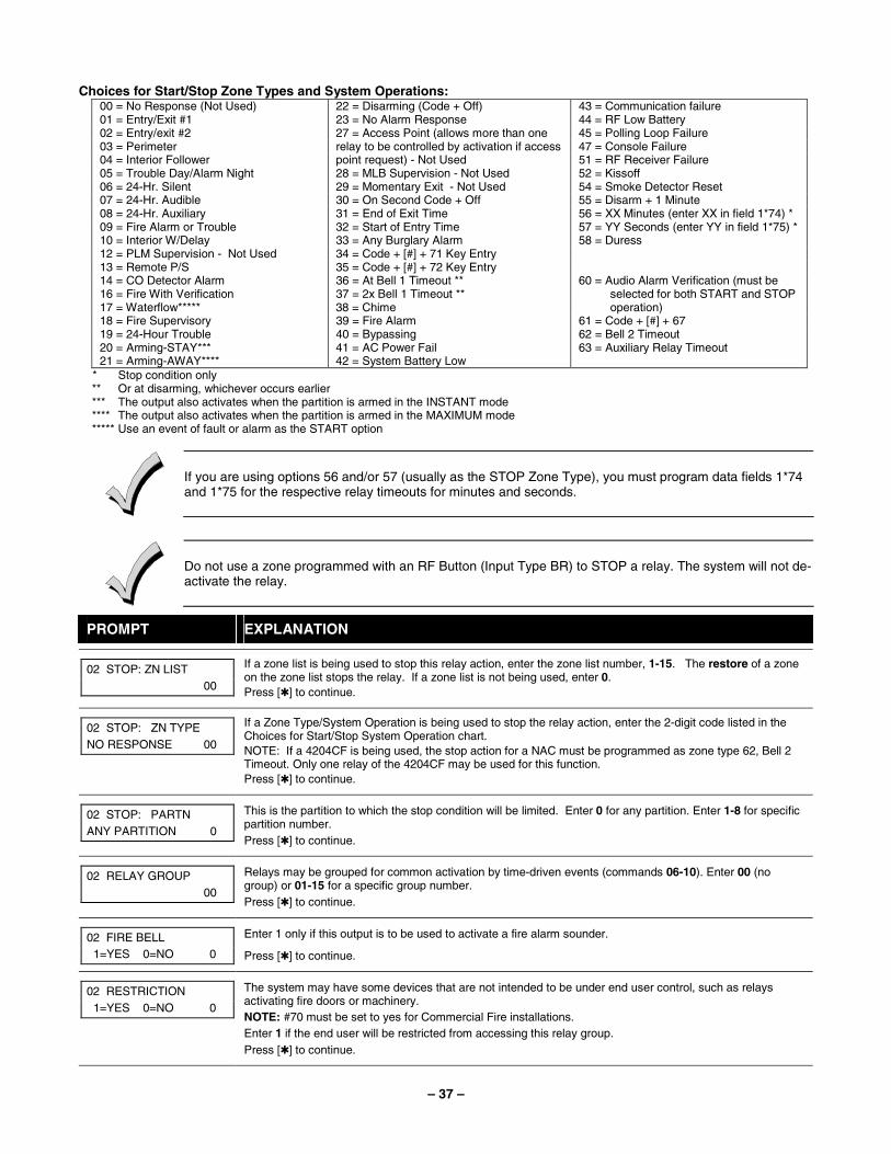
– 37 –
Choices for Start/Stop Zone Types and System Operations: 00 = No Response (Not Used) 22 = Disarming (Code + Off) 43 = Communication failure 01 = Entry/Exit #1 23 = No Alarm Response 44 = RF Low Battery 02 = Entry/exit #2 45 = Polling Loop Failure 03 = Perimeter 47 = Console Failure 04 = Interior Follower
27 = Access Point (allows more than one relay to be controlled by activation if access point request) - Not Used 51 = RF Receiver Failure
05 = Trouble Day/Alarm Night 28 = MLB Supervision - Not Used 52 = Kissoff 06 = 24-Hr. Silent 29 = Momentary Exit - Not Used 54 = Smoke Detector Reset 07 = 24-Hr. Audible 30 = On Second Code + Off 55 = Disarm + 1 Minute 08 = 24-Hr. Auxiliary 31 = End of Exit Time 56 = XX Minutes (enter XX in field 1*74) * 09 = Fire Alarm or Trouble 32 = Start of Entry Time 57 = YY Seconds (enter YY in field 1*75) * 10 = Interior W/Delay 33 = Any Burglary Alarm 58 = Duress 12 = PLM Supervision - Not Used 34 = Code + [#] + 71 Key Entry 13 = Remote P/S 35 = Code + [#] + 72 Key Entry 14 = CO Detector Alarm 36 = At Bell 1 Timeout ** 16 = Fire With Verification 37 = 2x Bell 1 Timeout ** 17 = Waterflow***** 38 = Chime
60 = Audio Alarm Verification (must be selected for both START and STOP operation)
18 = Fire Supervisory 39 = Fire Alarm 61 = Code + [#] + 67 19 = 24-Hour Trouble 40 = Bypassing 62 = Bell 2 Timeout 20 = Arming-STAY*** 41 = AC Power Fail 63 = Auxiliary Relay Timeout 21 = Arming-AWAY**** 42 = System Battery Low
* Stop condition only ** Or at disarming, whichever occurs earlier *** The output also activates when the partition is armed in the INSTANT mode **** The output also activates when the partition is armed in the MAXIMUM mode ***** Use an event of fault or alarm as the START option
If you are using options 56 and/or 57 (usually as the STOP Zone Type), you must program data fields 1*74 and 1*75 for the respective relay timeouts for minutes and seconds.
Do not use a zone programmed with an RF Button (Input Type BR) to STOP a relay. The system will not de-activate the relay.
PROMPT EXPLANATION
02 STOP: ZN LIST 00
If a zone list is being used to stop this relay action, enter the zone list number, 1-15. The restore of a zone on the zone list stops the relay. If a zone list is not being used, enter 0. Press [✱] to continue.
02 STOP: ZN TYPE NO RESPONSE 00
If a Zone Type/System Operation is being used to stop the relay action, enter the 2-digit code listed in the Choices for Start/Stop System Operation chart. NOTE: If a 4204CF is being used, the stop action for a NAC must be programmed as zone type 62, Bell 2 Timeout. Only one relay of the 4204CF may be used for this function. Press [✱] to continue.
02 STOP: PARTN ANY PARTITION 0
This is the partition to which the stop condition will be limited. Enter 0 for any partition. Enter 1-8 for specific partition number. Press [✱] to continue.
02 RELAY GROUP 00
Relays may be grouped for common activation by time-driven events (commands 06-10). Enter 00 (no group) or 01-15 for a specific group number. Press [✱] to continue.
02 FIRE BELL 1=YES 0=NO 0
Enter 1 only if this output is to be used to activate a fire alarm sounder.
Press [✱] to continue.
02 RESTRICTION 1=YES 0=NO 0
The system may have some devices that are not intended to be under end user control, such as relays activating fire doors or machinery. NOTE: #70 must be set to yes for Commercial Fire installations. Enter 1 if the end user will be restricted from accessing this relay group. Press [✱] to continue.
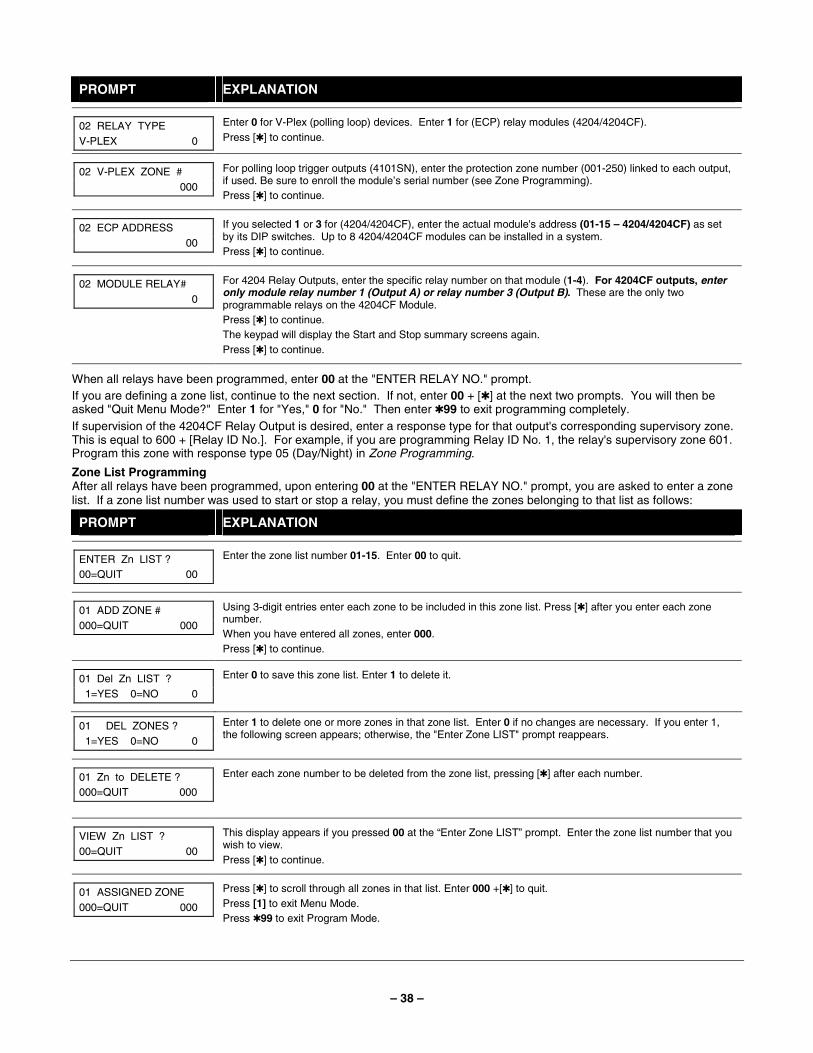
– 38 –
PROMPT EXPLANATION
02 RELAY TYPE V-PLEX 0
Enter 0 for V-Plex (polling loop) devices. Enter 1 for (ECP) relay modules (4204/4204CF). Press [✱] to continue.
02 V-PLEX ZONE # 000
For polling loop trigger outputs (4101SN), enter the protection zone number (001-250) linked to each output, if used. Be sure to enroll the module’s serial number (see Zone Programming). Press [✱] to continue.
02 ECP ADDRESS 00
If you selected 1 or 3 for (4204/4204CF), enter the actual module's address (01-15 – 4204/4204CF) as set by its DIP switches. Up to 8 4204/4204CF modules can be installed in a system. Press [✱] to continue.
02 MODULE RELAY# 0
For 4204 Relay Outputs, enter the specific relay number on that module (1-4). For 4204CF outputs, enter only module relay number 1 (Output A) or relay number 3 (Output B). These are the only two programmable relays on the 4204CF Module. Press [✱] to continue. The keypad will display the Start and Stop summary screens again. Press [✱] to continue.
When all relays have been programmed, enter 00 at the "ENTER RELAY NO." prompt. If you are defining a zone list, continue to the next section. If not, enter 00 + [✱] at the next two prompts. You will then be asked "Quit Menu Mode?" Enter 1 for "Yes," 0 for "No." Then enter ✱99 to exit programming completely. If supervision of the 4204CF Relay Output is desired, enter a response type for that output's corresponding supervisory zone. This is equal to 600 + [Relay ID No.]. For example, if you are programming Relay ID No. 1, the relay's supervisory zone 601. Program this zone with response type 05 (Day/Night) in Zone Programming.
Zone List Programming After all relays have been programmed, upon entering 00 at the "ENTER RELAY NO." prompt, you are asked to enter a zone list. If a zone list number was used to start or stop a relay, you must define the zones belonging to that list as follows:
PROMPT EXPLANATION
ENTER Zn LIST ? 00=QUIT 00
Enter the zone list number 01-15. Enter 00 to quit.
01 ADD ZONE # 000=QUIT 000
Using 3-digit entries enter each zone to be included in this zone list. Press [✱] after you enter each zone number. When you have entered all zones, enter 000. Press [✱] to continue.
01 Del Zn LIST ? 1=YES 0=NO 0
Enter 0 to save this zone list. Enter 1 to delete it.
01 DEL ZONES ? 1=YES 0=NO 0
Enter 1 to delete one or more zones in that zone list. Enter 0 if no changes are necessary. If you enter 1, the following screen appears; otherwise, the "Enter Zone LIST" prompt reappears.
01 Zn to DELETE ? 000=QUIT 000
Enter each zone number to be deleted from the zone list, pressing [✱] after each number.
VIEW Zn LIST ? 00=QUIT 00
This display appears if you pressed 00 at the “Enter Zone LIST” prompt. Enter the zone list number that you wish to view. Press [✱] to continue.
01 ASSIGNED ZONE 000=QUIT 000
Press [✱] to scroll through all zones in that list. Enter 000 +[✱] to quit. Press [1] to exit Menu Mode. Press ✱99 to exit Program Mode.
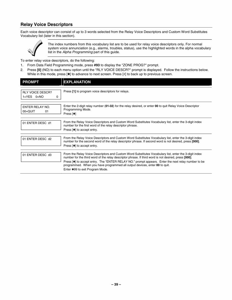
– 39 –
Relay Voice Descriptors
Each voice descriptor can consist of up to 3 words selected from the Relay Voice Descriptors and Custom Word Substitutes Vocabulary list (later in this section).
The index numbers from this vocabulary list are to be used for relay voice descriptors only. For normal system voice annunciation (e.g., alarms, troubles, status), use the highlighted words in the alpha vocabulary list in the Alpha Programming part of this guide.
To enter relay voice descriptors, do the following: 1. From Data Field Programming mode, press #93 to display the "ZONE PROG?" prompt. 2. Press [0] (NO) to each menu option until the "RLY VOICE DESCR?" prompt is displayed. Follow the instructions below.
While in this mode, press [✱] to advance to next screen. Press [#] to back up to previous screen.
PROMPT EXPLANATION
RLY VOICE DESCR? 1=YES 0=NO 0
Press [1] to program voice descriptors for relays.
ENTER RELAY NO. 00=QUIT 01
Enter the 2-digit relay number (01-32) for the relay desired, or enter 00 to quit Relay Voice Descriptor Programming Mode. Press [✱]
01 ENTER DESC d1
From the Relay Voice Descriptors and Custom Word Substitutes Vocabulary list, enter the 3-digit index number for the first word of the relay descriptor phrase. Press [✱] to accept entry.
01 ENTER DESC d2
From the Relay Voice Descriptors and Custom Word Substitutes Vocabulary list, enter the 3-digit index number for the second word of the relay descriptor phrase. If second word is not desired, press [000]. Press [✱] to accept entry.
01 ENTER DESC d3
From the Relay Voice Descriptors and Custom Word Substitutes Vocabulary list, enter the 3-digit index number for the third word of the relay descriptor phrase. If third word is not desired, press [000]. Press [✱] to accept entry. The “ENTER RELAY NO.” prompt appears. Enter the next relay number to be programmed. When you have programmed all output devices, enter 00 to quit. Enter ✱99 to exit Program Mode.
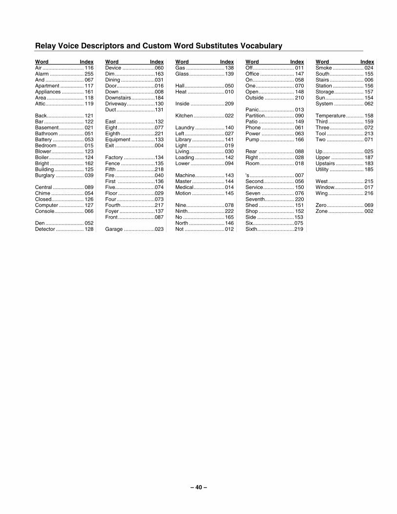
– 40 –
Relay Voice Descriptors and Custom Word Substitutes Vocabulary
Word Index Air ............................ 116 Alarm ....................... 255 And .......................... 067 Apartment ................ 117 Appliances ............... 161 Area ......................... 118 Attic.......................... 119 Back......................... 121 Bar ........................... 122 Basement................. 021 Bathroom ................. 051 Battery ..................... 053 Bedroom .................. 015 Blower...................... 123 Boiler........................ 124 Bright ....................... 162 Building .................... 125 Burglary ................... 039 Central ..................... 089 Chime ...................... 054 Closed...................... 126 Computer ................. 127 Console.................... 066 Den .......................... 052 Detector ................... 128
Word Index Device ......................060 Dim...........................163 Dining .......................031 Door..........................016 Down ........................008 Downstairs................184 Driveway...................130 Duct ..........................131 East ..........................132 Eight .........................077 Eighth .......................221 Equipment ................133 Exit ...........................004 Factory .....................134 Fence .......................135 Fifth ..........................218 Fire ...........................040 First .........................136 Five...........................074 Floor .........................029 Four ..........................073 Fourth .......................217 Foyer ........................137 Front .........................087 Garage .....................023
Word Index Gas ..........................138 Glass........................139 Hall...........................050 Heat .........................010 Inside .......................209 Kitchen .....................022 Laundry ....................140 Left ...........................027 Library ......................141 Light .........................019 Living........................030 Loading ....................142 Lower .......................094 Machine....................143 Master ......................144 Medical.....................014 Motion ......................145 Nine..........................078 Ninth.........................222 No ............................165 North ........................146 Not ...........................012
Word Index Off............................ 011 Office ....................... 147 On............................ 058 One.......................... 070 Open........................ 148 Outside .................... 210 Panic........................ 013 Partition.................... 090 Patio ........................ 149 Phone ...................... 061 Power ...................... 063 Pump ....................... 166 Rear ........................ 088 Right ........................ 028 Room ....................... 018 's .............................. 007 Second..................... 056 Service..................... 150 Seven ...................... 076 Seventh.................... 220 Shed ........................ 151 Shop ........................ 152 Side .........................153 Six............................075 Sixth.........................219
Word Index Smoke ..................... 024 South....................... 155 Stairs ....................... 006 Station ..................... 156 Storage.................... 157 Sun.......................... 154 System .................... 062 Temperature ............ 158 Third ........................ 159 Three....................... 072 Tool ......................... 213 Two ......................... 071 Up............................ 025 Upper ...................... 187 Upstairs ................... 183 Utility ....................... 185 West ........................ 215 Window.................... 017 Wing ........................ 216 Zero......................... 069 Zone ........................ 002
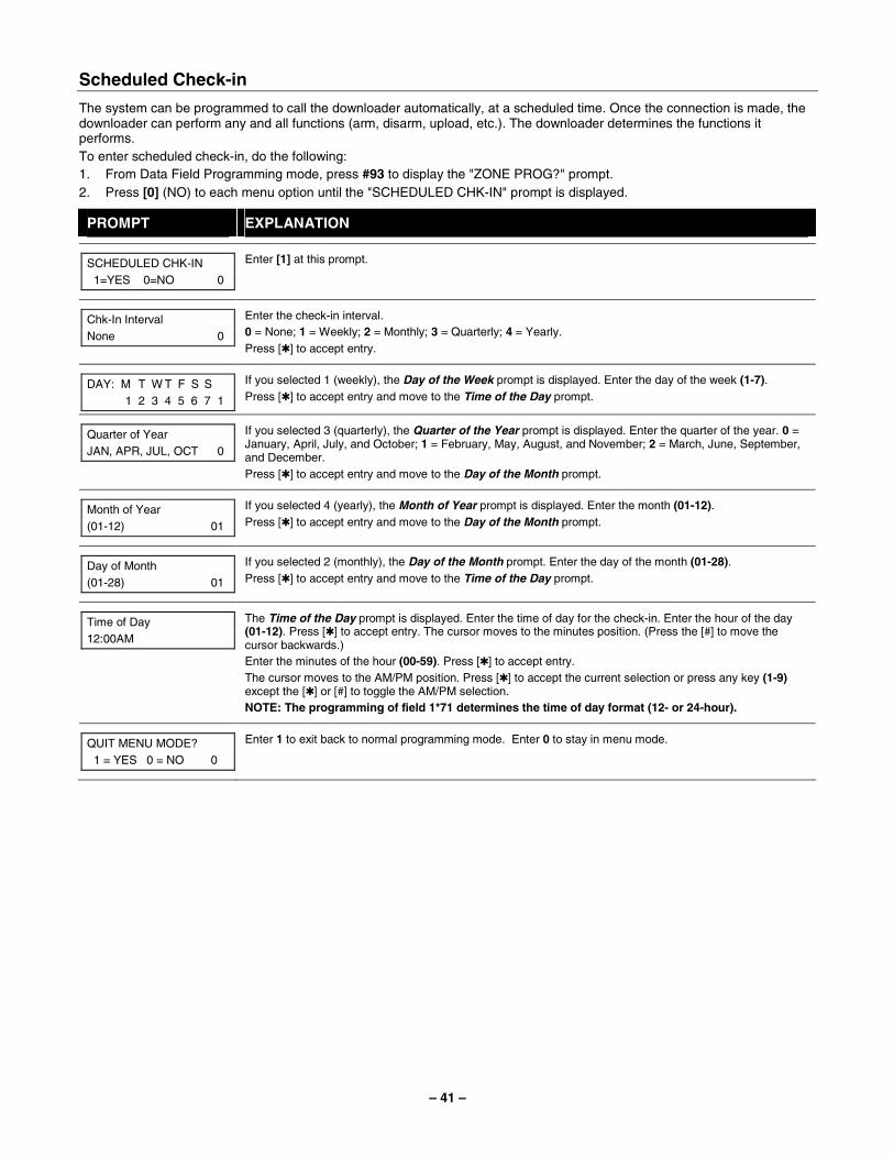
– 41 –
Scheduled Check-in
The system can be programmed to call the downloader automatically, at a scheduled time. Once the connection is made, the downloader can perform any and all functions (arm, disarm, upload, etc.). The downloader determines the functions it performs. To enter scheduled check-in, do the following: 1. From Data Field Programming mode, press #93 to display the "ZONE PROG?" prompt. 2. Press [0] (NO) to each menu option until the "SCHEDULED CHK-IN" prompt is displayed.
PROMPT EXPLANATION
SCHEDULED CHK-IN 1=YES 0=NO 0
Enter [1] at this prompt.
Chk-In Interval None 0
Enter the check-in interval. 0 = None; 1 = Weekly; 2 = Monthly; 3 = Quarterly; 4 = Yearly. Press [✱] to accept entry.
DAY: M T W T F S S 1 2 3 4 5 6 7 1
If you selected 1 (weekly), the Day of the Week prompt is displayed. Enter the day of the week (1-7). Press [✱] to accept entry and move to the Time of the Day prompt.
Quarter of Year JAN, APR, JUL, OCT 0
If you selected 3 (quarterly), the Quarter of the Year prompt is displayed. Enter the quarter of the year. 0 = January, April, July, and October; 1 = February, May, August, and November; 2 = March, June, September, and December. Press [✱] to accept entry and move to the Day of the Month prompt.
Month of Year (01-12) 01
If you selected 4 (yearly), the Month of Year prompt is displayed. Enter the month (01-12). Press [✱] to accept entry and move to the Day of the Month prompt.
Day of Month (01-28) 01
If you selected 2 (monthly), the Day of the Month prompt. Enter the day of the month (01-28). Press [✱] to accept entry and move to the Time of the Day prompt.
Time of Day 12:00AM
The Time of the Day prompt is displayed. Enter the time of day for the check-in. Enter the hour of the day (01-12). Press [✱] to accept entry. The cursor moves to the minutes position. (Press the [#] to move the cursor backwards.) Enter the minutes of the hour (00-59). Press [✱] to accept entry. The cursor moves to the AM/PM position. Press [✱] to accept the current selection or press any key (1-9) except the [✱] or [#] to toggle the AM/PM selection. NOTE: The programming of field 1*71 determines the time of day format (12- or 24-hour).
QUIT MENU MODE? 1 = YES 0 = NO 0
Enter 1 to exit back to normal programming mode. Enter 0 to stay in menu mode.
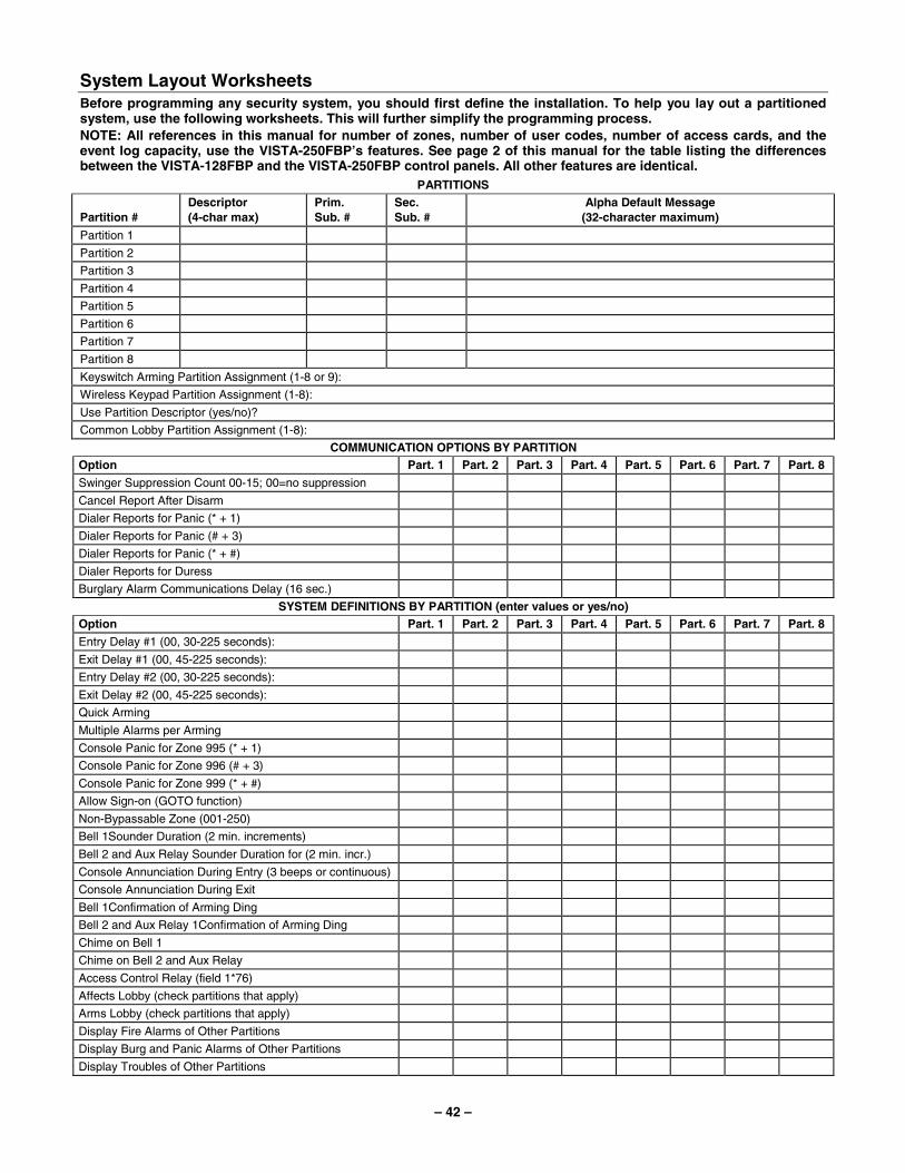
– 42 –
System Layout Worksheets Before programming any security system, you should first define the installation. To help you lay out a partitioned system, use the following worksheets. This will further simplify the programming process. NOTE: All references in this manual for number of zones, number of user codes, number of access cards, and the event log capacity, use the VISTA-250FBP’s features. See page 2 of this manual for the table listing the differences between the VISTA-128FBP and the VISTA-250FBP control panels. All other features are identical.
PARTITIONS Partition #
Descriptor (4-char max)
Prim. Sub. #
Sec. Sub. #
Alpha Default Message (32-character maximum)
Partition 1
Partition 2
Partition 3
Partition 4
Partition 5
Partition 6
Partition 7
Partition 8
Keyswitch Arming Partition Assignment (1-8 or 9):
Wireless Keypad Partition Assignment (1-8):
Use Partition Descriptor (yes/no)?
Common Lobby Partition Assignment (1-8):
COMMUNICATION OPTIONS BY PARTITION Option Part. 1 Part. 2 Part. 3 Part. 4 Part. 5 Part. 6 Part. 7 Part. 8
Swinger Suppression Count 00-15; 00=no suppression
Cancel Report After Disarm
Dialer Reports for Panic (* + 1)
Dialer Reports for Panic (# + 3)
Dialer Reports for Panic (* + #)
Dialer Reports for Duress
Burglary Alarm Communications Delay (16 sec.)
SYSTEM DEFINITIONS BY PARTITION (enter values or yes/no) Option Part. 1 Part. 2 Part. 3 Part. 4 Part. 5 Part. 6 Part. 7 Part. 8
Entry Delay #1 (00, 30-225 seconds):
Exit Delay #1 (00, 45-225 seconds):
Entry Delay #2 (00, 30-225 seconds):
Exit Delay #2 (00, 45-225 seconds):
Quick Arming
Multiple Alarms per Arming
Console Panic for Zone 995 (* + 1)
Console Panic for Zone 996 (# + 3)
Console Panic for Zone 999 (* + #)
Allow Sign-on (GOTO function)
Non-Bypassable Zone (001-250)
Bell 1Sounder Duration (2 min. increments)
Bell 2 and Aux Relay Sounder Duration for (2 min. incr.)
Console Annunciation During Entry (3 beeps or continuous)
Console Annunciation During Exit
Bell 1Confirmation of Arming Ding
Bell 2 and Aux Relay 1Confirmation of Arming Ding
Chime on Bell 1
Chime on Bell 2 and Aux Relay
Access Control Relay (field 1*76)
Affects Lobby (check partitions that apply)
Arms Lobby (check partitions that apply)
Display Fire Alarms of Other Partitions
Display Burg and Panic Alarms of Other Partitions
Display Troubles of Other Partitions
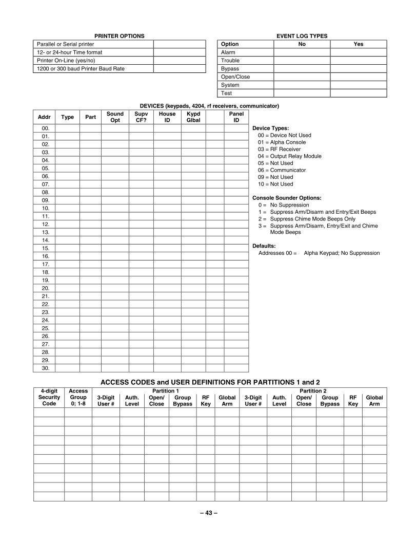
– 43 –
PRINTER OPTIONS
Parallel or Serial printer
12- or 24-hour Time format
Printer On-Line (yes/no)
1200 or 300 baud Printer Baud Rate
EVENT LOG TYPES
Option No Yes
Alarm
Trouble
Bypass
Open/Close
System
Test
DEVICES (keypads, 4204, rf receivers, communicator)
Addr Type Part Sound Opt
Supv CF?
House ID
Kypd Glbal Panel
ID
00.
01.
02.
03.
04.
05.
06.
07.
08.
09.
10.
11.
12.
13.
14.
15.
16.
17.
18.
19.
20.
21.
22.
23.
24.
25.
26.
27.
28.
29.
30.
Device Types: 00 = Device Not Used 01 = Alpha Console 03 = RF Receiver 04 = Output Relay Module 05 = Not Used 06 = Communicator 09 = Not Used 10 = Not Used
Console Sounder Options:
0 = No Suppression 1 = Suppress Arm/Disarm and Entry/Exit Beeps 2 = Suppress Chime Mode Beeps Only 3 = Suppress Arm/Disarm, Entry/Exit and Chime
Mode Beeps Defaults:
Addresses 00 = Alpha Keypad; No Suppression
ACCESS CODES and USER DEFINITIONS FOR PARTITIONS 1 and 2 Partition 1 Partition 2 4-digit
Security Code
Access Group 0; 1-8
3-Digit User #
Auth. Level
Open/ Close
Group Bypass
RF Key
Global Arm
3-Digit User #
Auth. Level
Open/Close
Group Bypass
RF Key
Global Arm
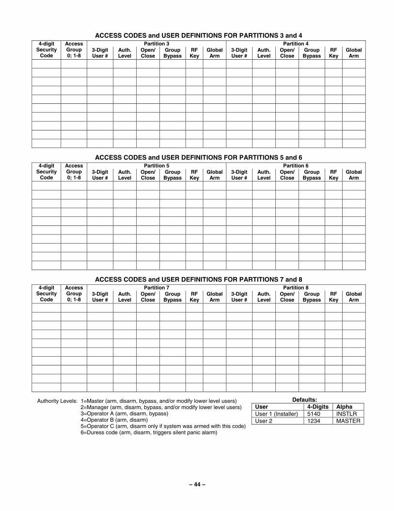
– 44 –
ACCESS CODES and USER DEFINITIONS FOR PARTITIONS 3 and 4 Partition 3 Partition 4 4-digit
Security Code
Access Group 0; 1-8
3-Digit User #
Auth. Level
Open/ Close
Group Bypass
RF Key
Global Arm
3-Digit User #
Auth. Level
Open/Close
Group Bypass
RF Key
Global Arm
ACCESS CODES and USER DEFINITIONS FOR PARTITIONS 5 and 6 Partition 5 Partition 6 4-digit
Security Code
Access Group 0; 1-8
3-Digit User #
Auth. Level
Open/ Close
Group Bypass
RF Key
Global Arm
3-Digit User #
Auth. Level
Open/Close
Group Bypass
RF Key
Global Arm
ACCESS CODES and USER DEFINITIONS FOR PARTITIONS 7 and 8 Partition 7 Partition 8 4-digit
Security Code
Access Group 0; 1-8
3-Digit User #
Auth. Level
Open/ Close
Group Bypass
RF Key
Global Arm
3-Digit User #
Auth. Level
Open/Close
Group Bypass
RF Key
Global Arm
Authority Levels: 1=Master (arm, disarm, bypass, and/or modify lower level users) 2=Manager (arm, disarm, bypass, and/or modify lower level users) 3=Operator A (arm, disarm, bypass) 4=Operator B (arm, disarm) 5=Operator C (arm, disarm only if system was armed with this code) 6=Duress code (arm, disarm, triggers silent panic alarm)
Defaults: User 4-Digits Alpha User 1 (Installer) 5140 INSTLR User 2 1234 MASTER
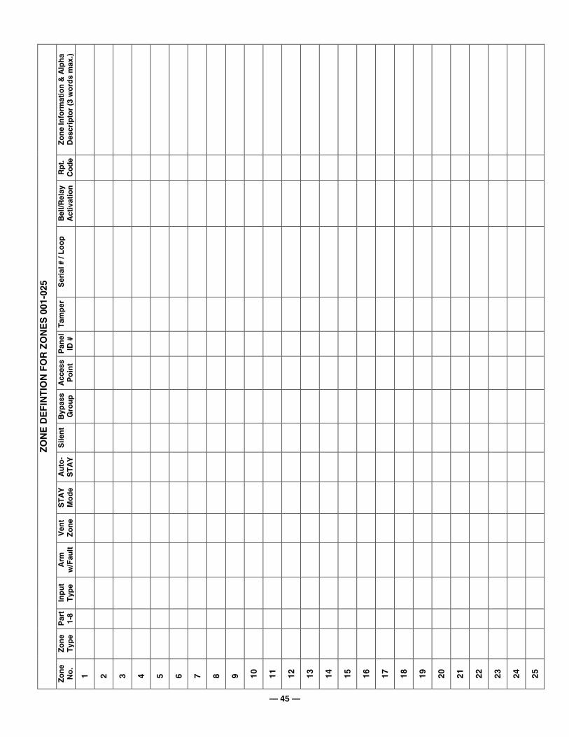
— 45 —
Zo
ne
Info
rmat
ion
& A
lph
a D
escr
ipto
r (3
wo
rds
max
.)
Rp
t.
Co
de
Bel
l/Rel
ay
Act
ivat
ion
Ser
ial #
/ L
oo
p
Tam
per
Pan
el
ID #
Acc
ess
Po
int
Byp
ass
Gro
up
Sile
nt
Au
to-
ST
AY
ST
AY
M
od
e
Ven
t Z
on
e
Arm
w
/Fau
lt
Inp
ut
Typ
e
Par
t 1-
8
Zo
ne
Typ
e
ZO
NE
DE
FIN
TIO
N F
OR
ZO
NE
S 0
01-0
25
Zo
ne
No
.
1
2
3
4
5
6
7
8
9
10
11
12
13
14
15
16
17
18
19
20
21
22
23
24
25

— 46 —
Zo
ne
Info
rmat
ion
& A
lph
a D
escr
ipto
r (3
wo
rds
max
.)
Rp
t.
Co
de
Bel
l/Rel
ay
Act
ivat
ion
Ser
ial #
/ L
oo
p
Tam
per
Pan
el
ID #
Acc
ess
Po
int
Byp
ass
Gro
up
Sile
nt
Au
to-
ST
AY
ST
AY
M
od
e
Ven
t Z
on
e
Arm
w
/Fau
lt
Inp
ut
Typ
e
Par
t 1-
8
Zo
ne
Typ
e
ZO
NE
DE
FIN
TIO
N F
OR
ZO
NE
S 0
26-0
50
Zo
ne
No
.
26
27
28
29
30
31
32
33
34
35
36
37
38
39
40
41
42
43
44
45
46
47
48
49
50

— 47 —
Zo
ne
Info
rmat
ion
& A
lph
a D
escr
ipto
r (3
wo
rds
max
.)
Rp
t.
Co
de
Bel
l/Rel
ay
Act
ivat
ion
Ser
ial #
/ L
oo
p
Tam
per
Pan
el
ID #
Acc
ess
Po
int
Byp
ass
Gro
up
Sile
nt
Au
to-
ST
AY
ST
AY
M
od
e
Ven
t Z
on
e
Arm
w
/Fau
lt
Inp
ut
Typ
e
Par
t 1-
8
Zo
ne
Typ
e
ZO
NE
DE
FIN
TIO
N F
OR
ZO
NE
S 0
51-0
75
Zo
ne
No
.
51
52
53
54
55
56
57
58
59
60
61
62
63
64
65
66
67
68
69
70
71
72
73
74
75
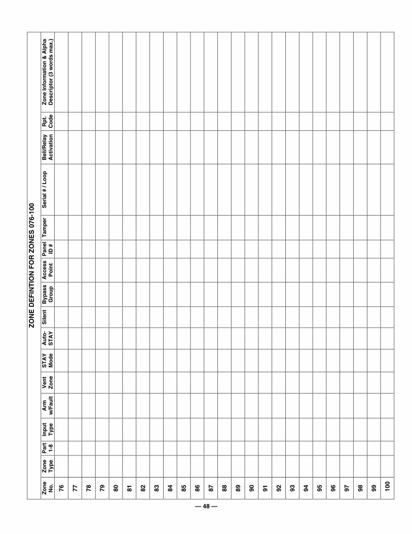
— 48 —
Zo
ne
Info
rmat
ion
& A
lph
a D
escr
ipto
r (3
wo
rds
max
.)
Rp
t.
Co
de
Bel
l/Rel
ay
Act
ivat
ion
Ser
ial #
/ L
oo
p
Tam
per
Pan
el
ID #
Acc
ess
Po
int
Byp
ass
Gro
up
Sile
nt
Au
to-
ST
AY
ST
AY
M
od
e
Ven
t Z
on
e
Arm
w
/Fau
lt
Inp
ut
Typ
e
Par
t 1-
8
Zo
ne
Typ
e
ZO
NE
DE
FIN
TIO
N F
OR
ZO
NE
S 0
76-1
00
Zo
ne
No
.
76
77
78
79
80
81
82
83
84
85
86
87
88
89
90
91
92
93
94
95
96
97
98
99
100
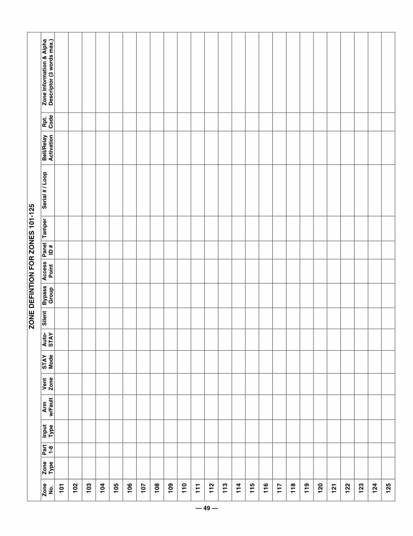
— 49 —
Zo
ne
Info
rmat
ion
& A
lph
a D
escr
ipto
r (3
wo
rds
max
.)
Rp
t.
Co
de
Bel
l/Rel
ay
Act
ivat
ion
Ser
ial #
/ L
oo
p
Tam
per
Pan
el
ID #
Acc
ess
Po
int
Byp
ass
Gro
up
Sile
nt
Au
to-
ST
AY
ST
AY
M
od
e
Ven
t Z
on
e
Arm
w
/Fau
lt
Inp
ut
Typ
e
Par
t 1-
8
Zo
ne
Typ
e
ZO
NE
DE
FIN
TIO
N F
OR
ZO
NE
S 1
01-1
25
Zo
ne
No
.
101
102
103
104
105
106
107
108
109
110
111
112
113
114
115
116
117
118
119
120
121
122
123
124
125

— 50 —
Zo
ne
Info
rmat
ion
& A
lph
a D
escr
ipto
r (3
wo
rds
max
.)
Rp
t.
Co
de
Bel
l/Rel
ay
Act
ivat
ion
Ser
ial #
/ L
oo
p
Tam
per
Pan
el
ID #
Acc
ess
Po
int
Byp
ass
Gro
up
Sile
nt
Au
to-
ST
AY
ST
AY
M
od
e
Ven
t Z
on
e
Arm
w
/Fau
lt
Inp
ut
Typ
e
Par
t 1-
8
Zo
ne
Typ
e
ZO
NE
DE
FIN
TIO
N F
OR
ZO
NE
S 1
26-1
50
Zo
ne
No
.
126
127
128
129
130
131
132
133
134
135
136
137
138
139
140
141
142
143
144
145
146
147
148
149
150

— 51 —
Zo
ne
Info
rmat
ion
& A
lph
a D
escr
ipto
r (3
wo
rds
max
.)
Rp
t.
Co
de
Bel
l/Rel
ay
Act
ivat
ion
Ser
ial #
/ L
oo
p
Tam
per
Pan
el
ID #
Acc
ess
Po
int
Byp
ass
Gro
up
Sile
nt
Au
to-
ST
AY
ST
AY
M
od
e
Ven
t Z
on
e
Arm
w
/Fau
lt
Inp
ut
Typ
e
Par
t 1-
8
Zo
ne
Typ
e
ZO
NE
DE
FIN
TIO
N F
OR
ZO
NE
S 1
51-1
75
Zo
ne
No
.
151
152
153
154
155
156
157
158
159
160
161
162
163
164
165
166
167
168
169
170
171
172
173
174
175

— 52 —
Zo
ne
Info
rmat
ion
& A
lph
a D
escr
ipto
r (3
wo
rds
max
.)
Rp
t.
Co
de
Bel
l/Rel
ay
Act
ivat
ion
Ser
ial #
/ L
oo
p
Tam
per
Pan
el
ID #
Acc
ess
Po
int
Byp
ass
Gro
up
Sile
nt
Au
to-
ST
AY
ST
AY
M
od
e
Ven
t Z
on
e
Arm
w
/Fau
lt
Inp
ut
Typ
e
Par
t 1-
8
Zo
ne
Typ
e
ZO
NE
DE
FIN
TIO
N F
OR
ZO
NE
S 1
76-2
00
Zo
ne
No
.
176
177
178
179
180
181
182
183
184
185
186
187
188
189
190
191
192
193
194
195
196
197
198
199
200

— 53 —
Zo
ne
Info
rmat
ion
& A
lph
a D
escr
ipto
r (3
wo
rds
max
.)
Rp
t.
Co
de
Bel
l/Rel
ay
Act
ivat
ion
Ser
ial #
/ L
oo
p
Tam
per
Pan
el
ID #
Acc
ess
Po
int
Byp
ass
Gro
up
Sile
nt
Au
to-
ST
AY
ST
AY
M
od
e
Ven
t Z
on
e
Arm
w
/Fau
lt
Inp
ut
Typ
e
Par
t 1-
8
Zo
ne
Typ
e
ZO
NE
DE
FIN
TIO
N F
OR
ZO
NE
S 2
01-2
25
Zo
ne
No
.
201
202
203
204
205
206
207
208
209
210
211
212
213
214
215
216
217
218
219
220
221
222
223
224
225
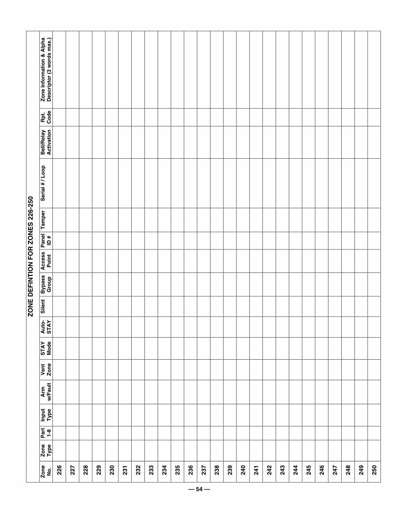
— 54 —
Zo
ne
Info
rmat
ion
& A
lph
a D
escr
ipto
r (3
wo
rds
max
.)
Rp
t.
Co
de
Bel
l/Rel
ay
Act
ivat
ion
Ser
ial #
/ L
oo
p
Tam
per
Pan
el
ID #
Acc
ess
Po
int
Byp
ass
Gro
up
Sile
nt
Au
to-
ST
AY
ST
AY
M
od
e
Ven
t Z
on
e
Arm
w
/Fau
lt
Inp
ut
Typ
e
Par
t 1-
8
Zo
ne
Typ
e
ZO
NE
DE
FIN
TIO
N F
OR
ZO
NE
S 2
26-2
50
Zo
ne
No
.
226
227
228
229
230
231
232
233
234
235
236
237
238
239
240
241
242
243
244
245
246
247
248
249
250
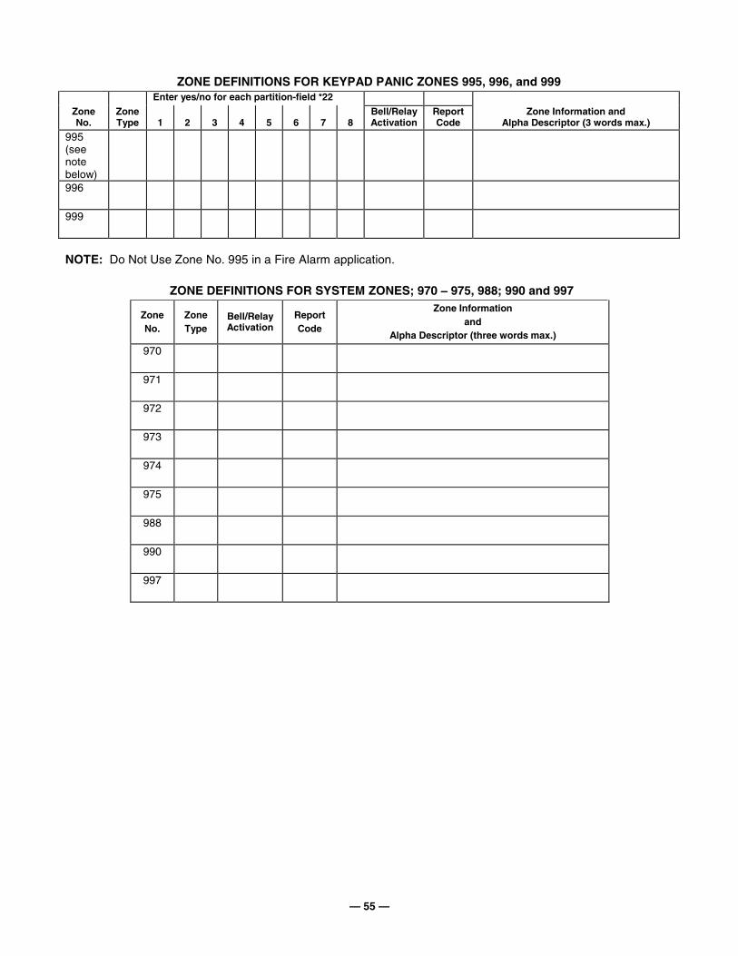
— 55 —
ZONE DEFINITIONS FOR KEYPAD PANIC ZONES 995, 996, and 999 Enter yes/no for each partition-field *22
Zone No.
Zone Type
1
2
3
4
5
6
7
8
Bell/Relay Activation
Report Code
Zone Information and Alpha Descriptor (3 words max.)
995 (see note below)
996
999
NOTE: Do Not Use Zone No. 995 in a Fire Alarm application.
ZONE DEFINITIONS FOR SYSTEM ZONES; 970 −−−− 975, 988; 990 and 997
Zone No.
Zone Type
Bell/Relay Activation
Report Code
Zone Information and
Alpha Descriptor (three words max.) 970
971
972
973
974
975
988
990
997
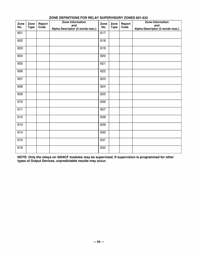
— 56 —
ZONE DEFINITIONS FOR RELAY SUPERVISORY ZONES 601-632
Zone No.
Zone Type
Report Code
Zone Information and
Alpha Descriptor (3 words max.)
Zone No.
Zone Type
Report Code
Zone Information and
Alpha Descriptor (3 words max.) 601
617
602
618
603
619
604
620
605
621
606
622
607
623
608
624
609
625
610
626
611
627
612
628
613
629
614
630
615
631
616
632
NOTE: Only the relays on 4204CF modules may be supervised. If supervision is programmed for other types of Output Devices, unpredictable results may occur.
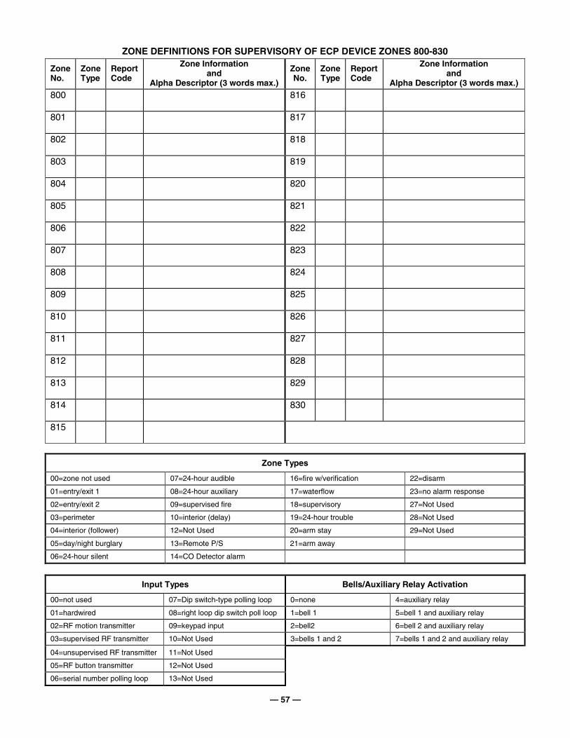
— 57 —
ZONE DEFINITIONS FOR SUPERVISORY OF ECP DEVICE ZONES 800-830
Zone No.
Zone Type
Report Code
Zone Information and
Alpha Descriptor (3 words max.)
Zone No.
Zone Type
Report Code
Zone Information and
Alpha Descriptor (3 words max.) 800
816
801
817
802
818
803
819
804
820
805
821
806
822
807
823
808
824
809
825
810
826
811
827
812
828
813
829
814
830
815
Zone Types
00=zone not used 07=24-hour audible 16=fire w/verification 22=disarm
01=entry/exit 1 08=24-hour auxiliary 17=waterflow 23=no alarm response
02=entry/exit 2 09=supervised fire 18=supervisory 27=Not Used
03=perimeter 10=interior (delay) 19=24-hour trouble 28=Not Used
04=interior (follower) 12=Not Used 20=arm stay 29=Not Used
05=day/night burglary 13=Remote P/S 21=arm away
06=24-hour silent 14=CO Detector alarm
Input Types Bells/Auxiliary Relay Activation
00=not used 07=Dip switch-type polling loop 0=none 4=auxiliary relay
01=hardwired 08=right loop dip switch poll loop 1=bell 1 5=bell 1 and auxiliary relay
02=RF motion transmitter 09=keypad input 2=bell2 6=bell 2 and auxiliary relay
03=supervised RF transmitter 10=Not Used 3=bells 1 and 2 7=bells 1 and 2 and auxiliary relay
04=unsupervised RF transmitter 11=Not Used
05=RF button transmitter 12=Not Used
06=serial number polling loop 13=Not Used
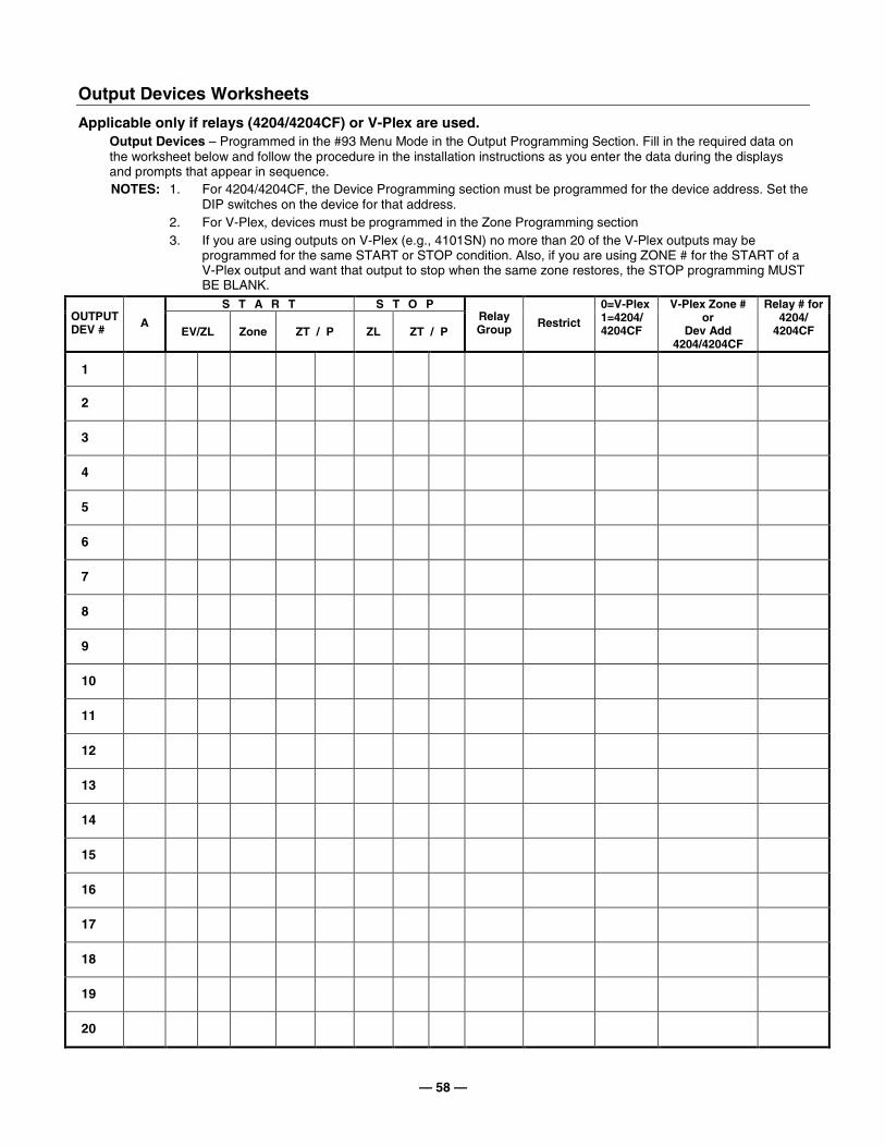
— 58 —
Output Devices Worksheets
Applicable only if relays (4204/4204CF) or V-Plex are used. Output Devices – Programmed in the #93 Menu Mode in the Output Programming Section. Fill in the required data on
the worksheet below and follow the procedure in the installation instructions as you enter the data during the displays and prompts that appear in sequence. NOTES: 1. For 4204/4204CF, the Device Programming section must be programmed for the device address. Set the
DIP switches on the device for that address. 2. For V-Plex, devices must be programmed in the Zone Programming section 3. If you are using outputs on V-Plex (e.g., 4101SN) no more than 20 of the V-Plex outputs may be
programmed for the same START or STOP condition. Also, if you are using ZONE # for the START of a V-Plex output and want that output to stop when the same zone restores, the STOP programming MUST BE BLANK.
S T A R T S T O P OUTPUT DEV #
A EV/ZL Zone ZT / P ZL ZT / P
Relay Group Restrict
0=V-Plex 1=4204/ 4204CF
V-Plex Zone # or
Dev Add 4204/4204CF
Relay # for 4204/
4204CF
1
2
3
4
5
6
7
8
9
10
11
12
13
14
15
16
17
18
19
20

— 59 —
OUTPUT DEVICES WORKSHEET (cont’d)
S T A R T S T O P OUTPUT DEV # A
EV/ZL Zone ZT / P ZL ZT / P Relay Group Restrict
0=V-Plex 1=4204/ 4204CF
V-Plex Zone # or
Dev Add 4204/4204CF
Relay # for 4204/
4204CF
21
22
23
24
25
26
27
28
29
30
31
32
33
34
35
36
37
38
39
40
41
42
43
44
45
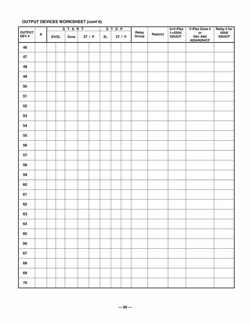
— 60 —
OUTPUT DEVICES WORKSHEET (cont’d)
S T A R T S T O P OUTPUT DEV # A
EV/ZL Zone ZT / P ZL ZT / P Relay Group Restrict
0=V-Plex 1=4204/ 4204CF
V-Plex Zone # or
Dev Add 4204/4204CF
Relay # for 4204/
4204CF
46
47
48
49
50
51
52
53
54
55
56
57
58
59
60
61
62
63
64
65
66
67
68
69
70
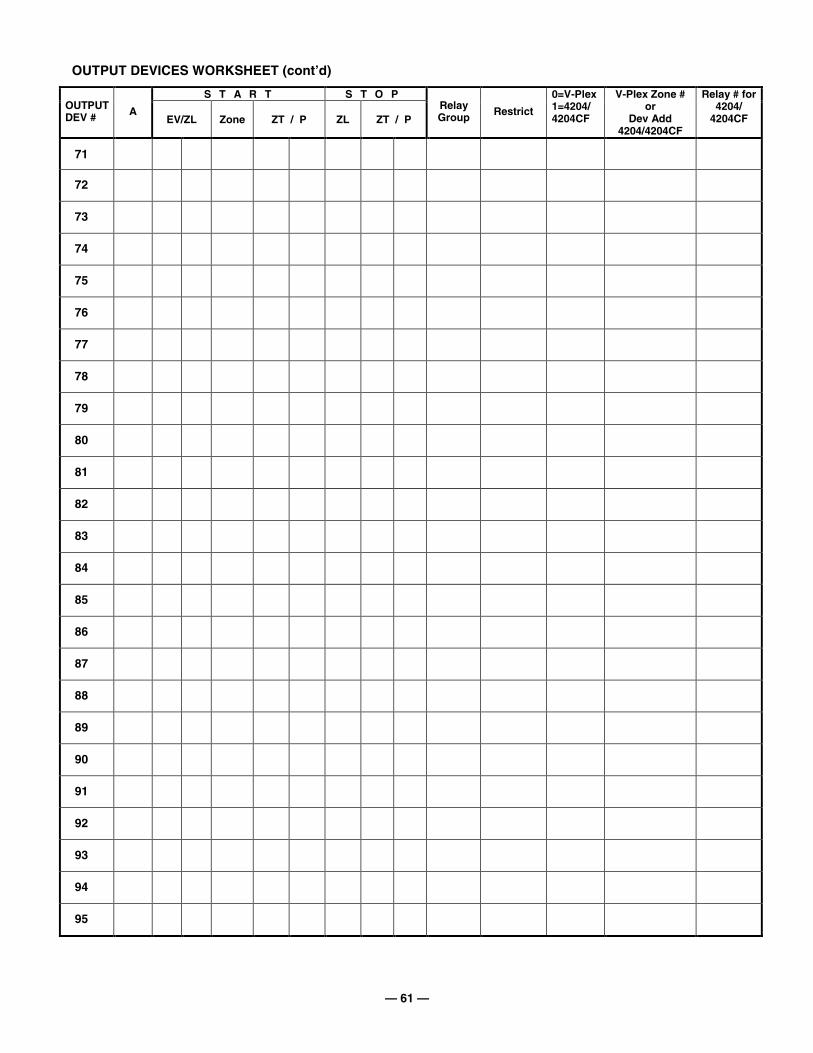
— 61 —
OUTPUT DEVICES WORKSHEET (cont’d)
S T A R T S T O P OUTPUT DEV # A
EV/ZL Zone ZT / P ZL ZT / P Relay Group Restrict
0=V-Plex 1=4204/ 4204CF
V-Plex Zone # or
Dev Add 4204/4204CF
Relay # for 4204/
4204CF
71
72
73
74
75
76
77
78
79
80
81
82
83
84
85
86
87
88
89
90
91
92
93
94
95
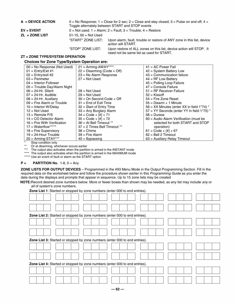
— 62 —
A = DEVICE ACTION 0 = No Response; 1 = Close for 2 sec; 2 = Close and stay closed; 3 = Pulse on and off; 4 = Toggle alternately between START and STOP events
EV = EVENT 0 = Not used; 1 = Alarm; 2 = Fault; 3 = Trouble; 4 = Restore ZL = ZONE LIST 01-15, 00 = Not Used
"START" ZONE LIST: Upon alarm, fault, trouble or restore of ANY zone in this list, device action will START.
"STOP" ZONE LIST: Upon restore of ALL zones on this list, device action will STOP. It need not be same list as used for START.
ZT = ZONE TYPE/SYSTEM OPERATION
Choices for Zone Type/System Operation are: 00 = No Response (Not Used) 21 = Arming-AWAY**** 41 = AC Power Fail 01 = Entry/Exit #1 22 = Disarming (Code + Off) 42 = System Battery Low 02 = Entry/exit #2 23 = No Alarm Response 43 = Communication failure 03 = Perimeter 44 = RF Low Battery 04 = Interior Follower 45 = Polling Loop Failure 05 = Trouble Day/Alarm Night
27 = Not Used
47 = Console Failure 06 = 24-Hr. Silent 28 = Not Used 51 = RF Receiver Failure 07 = 24-Hr. Audible 29 = Not Used 52 = Kissoff 08 = 24-Hr. Auxiliary 30 = On Second Code + Off 54 = Fire Zone Reset 09 = Fire Alarm or Trouble 31 = End of Exit Time 55 = Disarm + 1 Minute 10 = Interior W/Delay 32 = Start of Entry Time 56 = XX Minutes (enter XX in field 1*74) * 12 = Not Used 33 = Any Burglary Alarm 57 = YY Seconds (enter YY in field 1*75) * 13 = Remote P/S 34 = Code + [#] + 71 58 = Duress 14 = CO Detector Alarm 35 = Code + [#] + 72 16 = Fire With Verification 36 = At Bell Timeout ** 17 = Waterflow***** 37 = 2 Times Bell Timeout **
60 = Audio Alarm Verification (must be selected for both START and STOP operation)
18 = Fire Supervisory 38 = Chime 61 = Code + [#] + 67 19 = 24-Hour Trouble 39 = Fire Alarm 62 = Bell 2 Timeout 20 = Arming-STAY*** 40 = Bypassing 63 = Auxiliary Relay Timeout
* Stop condition only ** Or at disarming, whichever occurs earlier *** The output also activates when the partition is armed in the INSTANT mode **** The output also activates when the partition is armed in the MAXIMUM mode ***** Use an event of fault or alarm as the START option
P = PARTITION No. 1-8, 0 = Any
ZONE LISTS FOR OUTPUT DEVICES – Programmed in the #93 Menu Mode in the Output Programming Section. Fill in the required data on the worksheet below and follow the procedure shown earlier in this Programming Guide as you enter the data during the displays and prompts that appear in sequence. Up to 15 zone lists may be created NOTE: Record desired zone numbers below. More or fewer boxes than shown may be needed, as any list may include any or
all of system's zone numbers. Zone List 1: Started or stopped by zone numbers (enter 000 to end entries).
Zone List 2: Started or stopped by zone numbers (enter 000 to end entries).
Zone List 3: Started or stopped by zone numbers (enter 000 to end entries).
Zone List 4: Started or stopped by zone numbers (enter 000 to end entries).
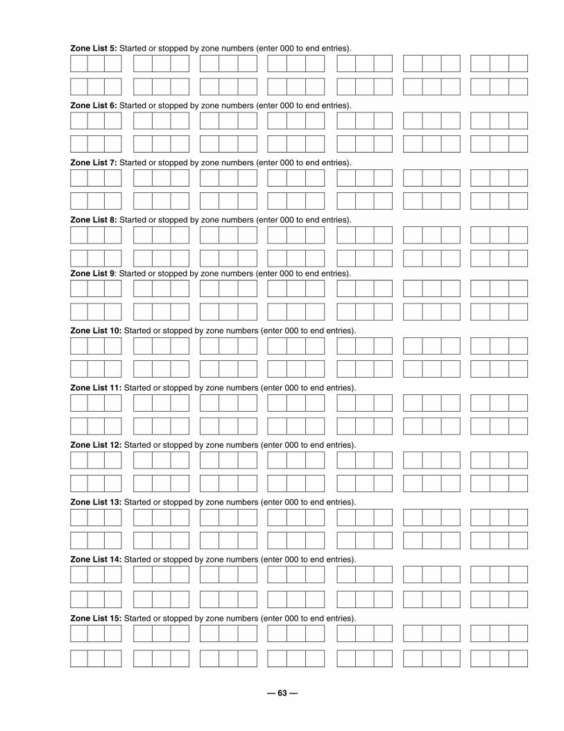
— 63 —
Zone List 5: Started or stopped by zone numbers (enter 000 to end entries).
Zone List 6: Started or stopped by zone numbers (enter 000 to end entries).
Zone List 7: Started or stopped by zone numbers (enter 000 to end entries).
Zone List 8: Started or stopped by zone numbers (enter 000 to end entries).
Zone List 9: Started or stopped by zone numbers (enter 000 to end entries).
Zone List 10: Started or stopped by zone numbers (enter 000 to end entries).
Zone List 11: Started or stopped by zone numbers (enter 000 to end entries).
Zone List 12: Started or stopped by zone numbers (enter 000 to end entries).
Zone List 13: Started or stopped by zone numbers (enter 000 to end entries).
Zone List 14: Started or stopped by zone numbers (enter 000 to end entries).
Zone List 15: Started or stopped by zone numbers (enter 000 to end entries).
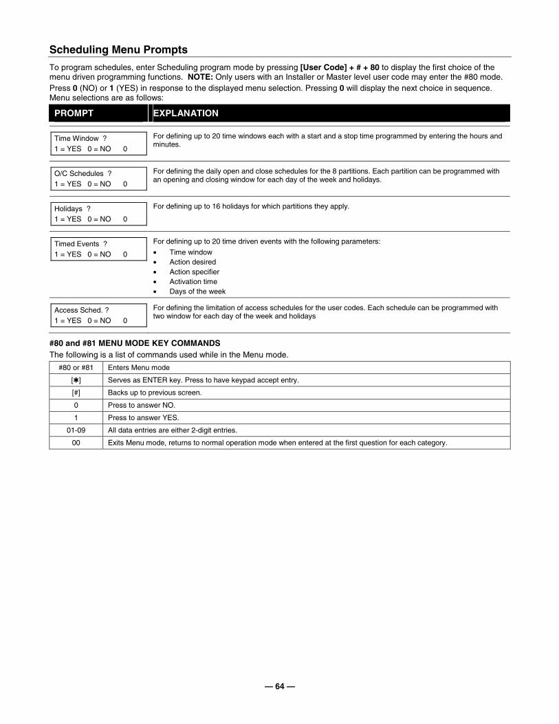
— 64 —
Scheduling Menu Prompts
To program schedules, enter Scheduling program mode by pressing [User Code] + # + 80 to display the first choice of the menu driven programming functions. NOTE: Only users with an Installer or Master level user code may enter the #80 mode. Press 0 (NO) or 1 (YES) in response to the displayed menu selection. Pressing 0 will display the next choice in sequence. Menu selections are as follows:
PROMPT EXPLANATION
Time Window ? 1 = YES 0 = NO 0
For defining up to 20 time windows each with a start and a stop time programmed by entering the hours and minutes.
O/C Schedules ? 1 = YES 0 = NO 0
For defining the daily open and close schedules for the 8 partitions. Each partition can be programmed with an opening and closing window for each day of the week and holidays.
Holidays ? 1 = YES 0 = NO 0
For defining up to 16 holidays for which partitions they apply.
Timed Events ? 1 = YES 0 = NO 0
For defining up to 20 time driven events with the following parameters:
• Time window • Action desired • Action specifier • Activation time • Days of the week
Access Sched. ? 1 = YES 0 = NO 0
For defining the limitation of access schedules for the user codes. Each schedule can be programmed with two window for each day of the week and holidays
#80 and #81 MENU MODE KEY COMMANDS The following is a list of commands used while in the Menu mode.
#80 or #81 Enters Menu mode
[✱] Serves as ENTER key. Press to have keypad accept entry.
[#] Backs up to previous screen.
0 Press to answer NO.
1 Press to answer YES.
01-09 All data entries are either 2-digit entries.
00 Exits Menu mode, returns to normal operation mode when entered at the first question for each category.
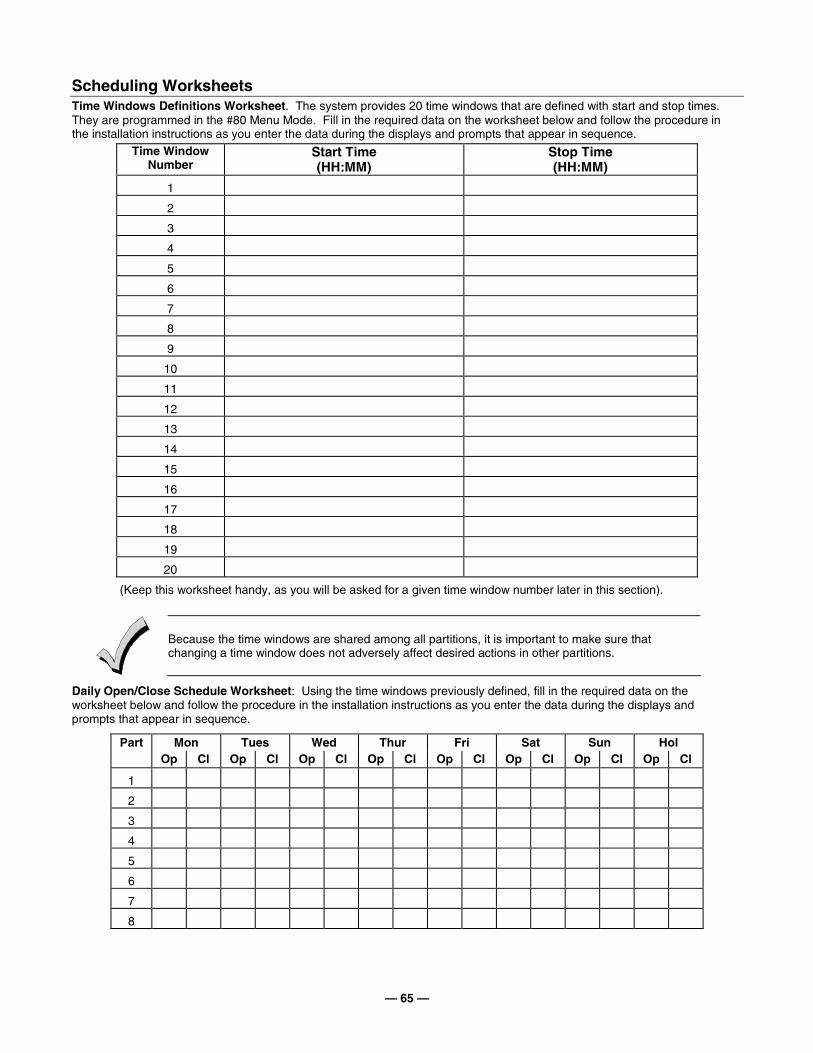
— 65 —
Scheduling Worksheets Time Windows Definitions Worksheet. The system provides 20 time windows that are defined with start and stop times. They are programmed in the #80 Menu Mode. Fill in the required data on the worksheet below and follow the procedure in the installation instructions as you enter the data during the displays and prompts that appear in sequence.
Time Window Number
Start Time (HH:MM)
Stop Time (HH:MM)
1
2
3
4
5
6
7
8
9
10
11
12
13
14
15
16
17
18
19
20
(Keep this worksheet handy, as you will be asked for a given time window number later in this section).
Because the time windows are shared among all partitions, it is important to make sure that changing a time window does not adversely affect desired actions in other partitions.
Daily Open/Close Schedule Worksheet: Using the time windows previously defined, fill in the required data on the worksheet below and follow the procedure in the installation instructions as you enter the data during the displays and prompts that appear in sequence.
Part Mon Tues Wed Thur Fri Sat Sun Hol Op Cl Op Cl Op Cl Op Cl Op Cl Op Cl Op Cl Op Cl
1
2
3
4
5
6
7
8
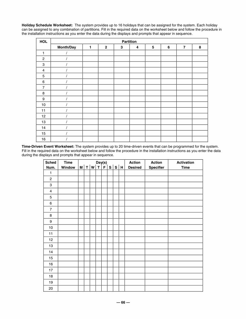
— 66 —
Holiday Schedule Worksheet: The system provides up to 16 holidays that can be assigned for the system. Each holiday can be assigned to any combination of partitions. Fill in the required data on the worksheet below and follow the procedure in the installation instructions as you enter the data during the displays and prompts that appear in sequence.
HOL Partition
Month/Day 1 2 3 4 5 6 7 8
1 / 2 / 3 / 4 / 5 / 6 / 7 / 8 / 9 /
10 / 11 / 12 / 13 / 14 / 15 / 16 /
Time-Driven Event Worksheet: The system provides up to 20 time-driven events that can be programmed for the system. Fill in the required data on the worksheet below and follow the procedure in the installation instructions as you enter the data during the displays and prompts that appear in sequence.
Sched Time Day(s) Action Action Activation Num. Window M T W T F S S H Desired Specifier Time
1
2
3
4
5
6
7
8
9
10
11
12
13
14
15
16
17
18
19
20
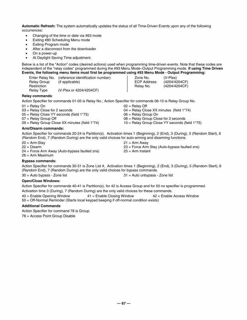
— 67 —
Automatic Refresh: The system automatically updates the status of all Time-Driven Events upon any of the following occurrences:
• Changing of the time or date via #63 mode • Exiting #80 Scheduling Menu mode • Exiting Program mode • After a disconnect from the downloader • On a power-up • At Daylight Saving Time adjustment.
Below is a list of the "Action" codes (desired actions) used when programming time-driven events. Note that these codes are independent of the "relay codes" programmed during the #93 Menu Mode–Output Programming mode. If using Time Driven Events, the following menu items must first be programmed using #93 Menu Mode - Output Programming:
Enter Relay No. (reference identification number) Relay Group (if applicable) Restriction Relay Type (V-Plex or 4204/4204CF)
Zone No. (V-Plex) ECP Address (4204/4204CF) Relay No. (4204/4204CF)
Relay commands: Action Specifier for commands 01-05 is Relay No.; Action Specifier for commands 06-10 is Relay Group No. 01 = Relay On 02 = Relay Off 03 = Relay Close for 2 seconds 04 = Relay Close XX minutes (field 1*74) 05 = Relay Close YY seconds (field 1*75) 06 = Relay Group On 07 = Relay Group Off 08 = Relay Group Close for 2 seconds 09 = Relay Group Close XX minutes (field 1*74) 10 = Relay Group Close YY seconds (field 1*75)
Arm/Disarm commands: Action Specifier for commands 20-24 is Partition(s). Activation times 1 (Beginning), 2 (End), 3 (During), 5 (Random Start), 6 (Random End), 7 (Random During) are the only valid choices for auto-arming and disarming functions. 20 = Arm-Stay 21 = Arm Away 22 = Disarm 23 = Force Arm Stay (Auto-bypass faulted zns) 24 = Force Arm Away (Auto-bypass faulted zns) 25 = Arm Instant 26 = Arm Maximum
Bypass commands: Action Specifier for commands 30-31 is Zone List #, Activation times 1 (Beginning), 2 (End), 3 (During), 5 (Random Start), 6 (Random End), 7 (Random During) are the only valid choices for bypass commands. 30 = Auto bypass - Zone list 31 = Auto unbypass - Zone list
Open/Close Windows: Action Specifier for commands 40-41 is Partition(s), for 42 is Access Group and for 50 no specifier is programmed. Activation time 3 (During), 7 (Random During) are the only valid choices for these commands. 40 = Enable Opening Window 41 = Enable Closing Window 42 = Enable Access Window 50 = Off-Normal Reminder (Starts local keypad beeping if off-normal condition exists)
Additional Commands Action Specifier for command 78 is Group. 78 = Access Point Group Disable
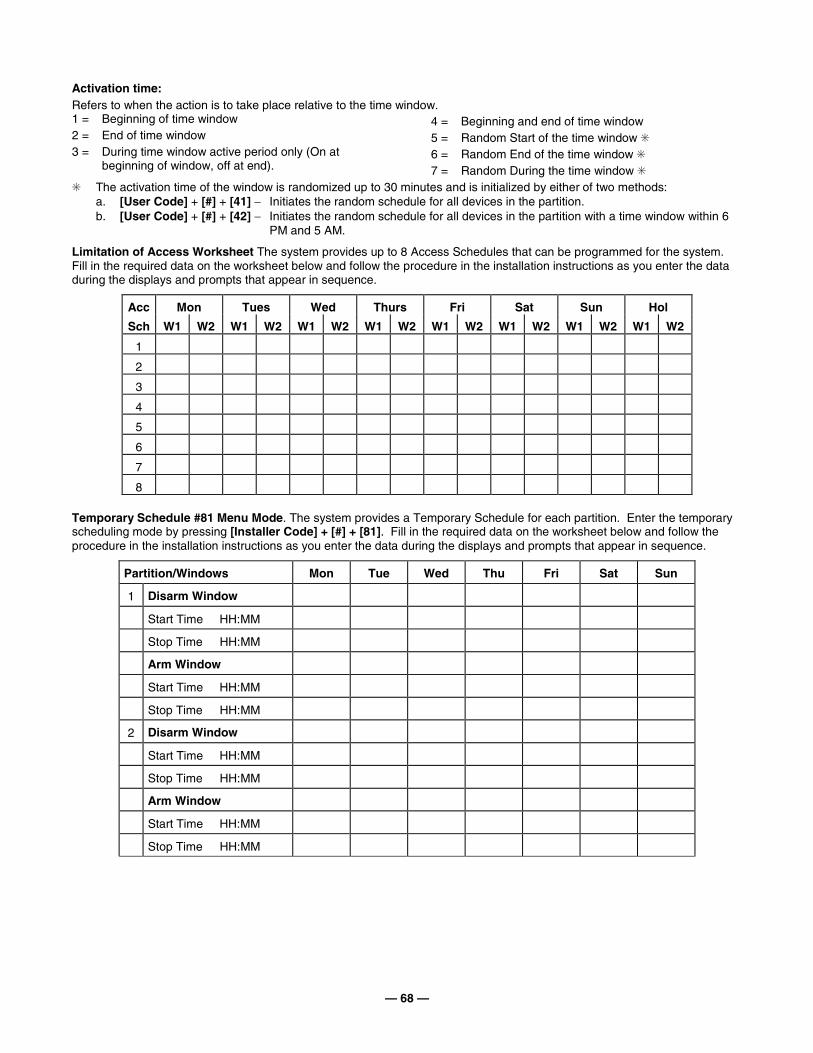
— 68 —
Activation time: Refers to when the action is to take place relative to the time window. 1 = Beginning of time window 2 = End of time window 3 = During time window active period only (On at
beginning of window, off at end).
4 = Beginning and end of time window 5 = Random Start of the time window ✳ 6 = Random End of the time window ✳ 7 = Random During the time window ✳
✳ The activation time of the window is randomized up to 30 minutes and is initialized by either of two methods: a. [User Code] + [#] + [41] − Initiates the random schedule for all devices in the partition. b. [User Code] + [#] + [42] − Initiates the random schedule for all devices in the partition with a time window within 6
PM and 5 AM.
Limitation of Access Worksheet The system provides up to 8 Access Schedules that can be programmed for the system. Fill in the required data on the worksheet below and follow the procedure in the installation instructions as you enter the data during the displays and prompts that appear in sequence.
Acc Mon Tues Wed Thurs Fri Sat Sun Hol
Sch W1 W2 W1 W2 W1 W2 W1 W2 W1 W2 W1 W2 W1 W2 W1 W2
1
2
3
4
5
6
7
8
Temporary Schedule #81 Menu Mode. The system provides a Temporary Schedule for each partition. Enter the temporary scheduling mode by pressing [Installer Code] + [#] + [81]. Fill in the required data on the worksheet below and follow the procedure in the installation instructions as you enter the data during the displays and prompts that appear in sequence.
Partition/Windows Mon Tue Wed Thu Fri Sat Sun
1 Disarm Window
Start Time HH:MM
Stop Time HH:MM
Arm Window
Start Time HH:MM
Stop Time HH:MM
2 Disarm Window
Start Time HH:MM
Stop Time HH:MM
Arm Window
Start Time HH:MM
Stop Time HH:MM
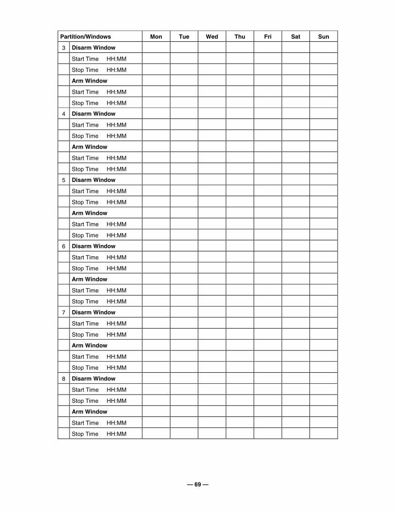
— 69 —
Partition/Windows Mon Tue Wed Thu Fri Sat Sun
3 Disarm Window
Start Time HH:MM
Stop Time HH:MM
Arm Window
Start Time HH:MM
Stop Time HH:MM
4 Disarm Window
Start Time HH:MM
Stop Time HH:MM
Arm Window
Start Time HH:MM
Stop Time HH:MM
5 Disarm Window
Start Time HH:MM
Stop Time HH:MM
Arm Window
Start Time HH:MM
Stop Time HH:MM
6 Disarm Window
Start Time HH:MM
Stop Time HH:MM
Arm Window
Start Time HH:MM
Stop Time HH:MM
7 Disarm Window
Start Time HH:MM
Stop Time HH:MM
Arm Window
Start Time HH:MM
Stop Time HH:MM
8 Disarm Window
Start Time HH:MM
Stop Time HH:MM
Arm Window
Start Time HH:MM
Stop Time HH:MM

— 70 —
NOTES
— 71 —
V25
0FB
P-S
OC
-V5
VIS
TA-1
28F
BP
/ V
ISTA
-250
FB
PS
UM
MA
RY
OF
CO
NN
EC
TIO
NS
TR
AN
SF
OR
ME
RW
/EN
CL
OS
UR
EA
DE
MC
O N
o.14
51(s
uppl
ied)
INP
UT
: 120
VA
C,
60H
Z,
1.0
A m
ax. C
onne
ct to
a
dedi
cate
d ci
rcui
t.
See
inst
ruct
ions
for
prop
er e
arth
gro
und
conn
ectio
ns
12
34
56
78
910
30
PROGRAMMABLEAS KEYSWITCH LOOP
PROGRAMMABLEAS TAMPER LOOP
2-WIRE GLASS BREAKDETECTOR LOOP
2k (
note
6)
+
Data in
Data out+
BA
CK
-UP
LIN
E S
EIZ
ELE
D (
GR
EE
N)
Con
nect
to m
ain
PC
Bhe
ader
J3
usin
g rib
bon
cabl
e (s
uppl
ied)
BA
CK
-UP
TLM
ON
HO
OK
VO
LTA
GE
TH
RE
SH
OLD
(B
LUE
)IN
TA
CT
: 25V
CU
T: 1
3V
OP
TIO
NA
L 5
140D
LM
BA
CK
-UP
DIA
LE
R M
OD
UL
E
MA
IN P
CB
SH
IEL
D
BA
CK
-UP
PH
ON
E J
AC
KS
EE
TE
LCO
JA
CK
SH
OC
K
WA
RN
ING
B
ELO
W
J2
Mak
e co
nnec
tions
usi
ng 4
142T
R c
able
VO
LT
AG
E
TR
IGG
ER
S(n
ot s
uper
vise
d)
J3
1
2 3
4
5
6
7
8
9J4
Mak
e co
nnec
tions
usi
ng
4142
TR
cab
le (
supp
lied)
KE
YP
AD
PO
RT
#2
BE
LL 1
W1
(WH
ITE
)
BE
LL 2
W4
(WH
ITE
)
BLK
+
R
ED
OP
TIO
NA
L R
EM
OV
AB
LE
TE
RM
INA
L B
LO
CK
KIT
: A
DE
MC
O N
O. 4
142B
LK
BELL
HO
RN
BELL
HO
RN
N.C
.
N.O
.
N.C
.
N.O
.
TO
OT
HE
R D
EV
ICE
S
2k
2k
2k
2k
ZO
NE
4
2k
AC
WIR
ING
IS
SU
PE
RV
ISE
DB
ELL
1B
ELL
2+
+
ALA
RM
PO
LAR
ITY
SH
OW
N
N.O.
POLE
N.C. SPARE AUX POWR #1
AU
XIL
IAR
Y P
OW
ER
#1
1.0A
MA
X (
ST
AN
DB
Y)
1.7A
MA
X (
ALA
RM
) (S
ee N
ote
1.)
Max
. Im
peda
nce:
0.6
Ohm
sS
peci
al A
pplic
atio
n C
ircui
t.
Fire
& B
urgl
ary
Dev
ices
on
the
EC
P B
usm
ust b
e is
olat
ed u
sing
an
EC
P Is
olat
or.
Ref
er to
Inst
ruct
ions
for
spec
ific
exam
ples
.
EC
P B
us: M
ax. L
ine
Impe
danc
e: 5
0 O
hms
Spe
cial
App
licat
ion
Circ
uit.
Con
nect
to 1
2V, 1
2AH
min
/34.
4AH
max
lead
aci
d ba
tterie
s us
ing
cabl
es s
uppl
ied.
S
ee in
stru
ctio
ns fo
r re
quire
d ca
paci
ty.
Flo
at c
harg
ing
volta
ge: 1
3.7V
DC
. Bat
tery
norm
ally
nee
d no
t be
repl
aced
for
at le
ast 3
yrs
.
J4 K
EY
PA
D P
OR
T #
2S
ee in
str.
reg
ardi
ng p
ort #
2 us
e1.
GR
OU
ND
(to
key
pad
blac
k w
ire)
4. D
AT
A IN
2 (
to k
eypa
d gr
een
wire
)5.
AU
X P
WR
#2
(to
keyp
ad r
ed w
ire)
R
atin
g: 1
0 -
14 V
DC
,
400
mA
max
. See
not
e 1
7. D
AT
A O
UT
2 (
to k
eypa
d ye
llow
wire
)W
6(B
LUE
)
INT
ER
FA
CE
TO
514
0DL
M
MA
IN D
IALE
R O
N H
OO
KV
OLT
AG
E T
HR
ES
HO
LD
INT
AC
T:2
5VC
UT
: 13V
BA
CK
-UP
DIA
LER
EA
RT
H
GR
OU
ND
SC
RE
W
(wire
to m
ain
PC
Bte
rmin
al #
30)
J2 V
OL
TA
GE
TR
IGG
ER
SS
ee in
stru
ctio
ns fo
r tr
igge
r us
e an
d pr
ogra
mm
ing
(de
faul
t fun
ctio
ns s
how
n)1.
OU
T 4
(S
ILE
NT
PA
NIC
/DU
RE
SS
)2.
OU
T 7
(T
RO
UB
LE)
3. O
UT
3 (
BU
RG
LAR
Y/A
UD
IBLE
PA
NIC
)4.
OU
T 6
(S
UP
ER
VIS
OR
Y)
5. O
UT
2 (
FIR
E)
6. O
UT
5 (
RE
MO
TE
KE
YP
AD
SO
UN
DE
R)
7. O
UT
1 (
OP
EN
/CLO
SE
)8.
GR
OU
ND
9. IN
1 (
N.O
. LO
OP
)R
AT
ING
S: O
UT
1, 5
, 7:
LO
W: 2
K T
O G
RO
UN
D
H
IGH
: 10
- 14
VD
C, 2
0mA
MA
XO
TH
ER
OU
TS
: LO
W: 1
K T
O G
RO
UN
D
HIG
H: 1
0 -
14V
DC
TH
RU
5K
Atta
ch 5
140D
LM m
odul
e to
mai
n P
CB
shi
eld
usin
g 4
stan
doffs
(su
pplie
d)
1
2 3
4
5
6
7
8
9
BA
TT
ER
Y T
AB
S
PIN
S 2
, 3, 6
, 8 &
9 N
OT
US
ED
RJ3
1X
MA
IN
PH
ON
E J
AC
K
BE
LL
OU
TP
UT
SA
UX
. RE
LA
Y
INP
UT
OU
TP
UT
CO
NN
EC
TIO
N O
F T
HE
FIR
E A
LAR
MS
IGN
AL
TO
A F
IRE
ALA
RM
HE
AD
-Q
UA
RT
ER
S O
R A
CE
NT
RA
L S
TA
TIO
NS
HA
LL B
E P
ER
MIT
TE
D O
NLY
WIT
HT
HE
AP
PR
OV
AL
OF
TH
E L
OC
AL
AU
TH
OR
ITY
HA
VIN
G J
UR
ISD
ICT
ION
.T
HE
BU
RG
LAR
Y A
LAR
M S
IGN
AL
SH
ALL
NO
T B
E C
ON
NE
CT
ED
TO
A
PO
LIC
E E
ME
RG
EN
CY
NU
MB
ER
.
PO
LL
ING
L
OO
P
TO
PR
EV
EN
TR
ISK
OF
E
LEC
TR
ICA
LS
HO
CK
,D
ISC
ON
NE
CT
TE
LCO
JAC
K B
EF
OR
ES
ER
VIC
ING
TH
IS P
AN
ELC
onne
ct
RJ3
1X u
sing
ca
ble
supp
lied.
S
uper
visi
on is
pr
ogra
mm
able
OU
TP
UT
: 18V
AC
7
2VA
BL
BL
BLA
CK
WH
RJ3
1X
(co
nnec
t usi
ng s
uppl
ied
cabl
e)S
uper
visi
on is
pro
gram
mab
le
EA
RT
H G
RO
UN
D
• R
atin
gs fo
r zo
nes
1,2:
-
2mA
max
for
all s
mok
e de
t.
(up
to 1
6 de
tect
ors
of th
e ty
pe
spe
cifie
d in
the
inst
ruct
ions
can
b
e us
ed)
-
UL
com
patib
ility
ID: A
TR
NS
FM
R
TE
ST
BU
RG
LA
RY
SY
ST
EM
WE
EK
LY
The
514
0DLM
Dia
ler
Com
plie
s w
ith F
CC
Rul
es, P
art 6
8F
CC
Reg
. No.
: AC
398U
-686
28-M
O-N
Rin
ger
Equ
ival
ence
: 0.7
B
5193
SDSM
OKE
4208SNF
2829
4208U
The
Mai
n D
iale
r C
ompl
ies
with
FC
C R
ules
, Par
t 68
FC
C R
eg. N
o.: A
C3-
US
A-6
8192
-AL-
ER
inge
r E
quiv
alen
ce: 0
.7B
FO
R D
RY
, IN
DO
OR
US
E O
NL
Y
The
impe
danc
e at
whi
ch a
gro
und
faul
t is
annu
ncia
ted
is 1
,000
ohm
s
Spe
cial
App
licat
ion
Circ
uit
Con
nect
Onl
y F
ire K
eypa
ds to
AU
X P
WR
# 2
.
Eac
h ou
tput
is C
lass
B a
nd m
ay b
e se
lect
ed fo
r S
tyle
Ysu
perv
isio
n or
no
supe
rvis
ion.
(S
ee m
ain
PC
B ju
mpe
rsW
1, W
4 an
d #9
3 M
enu
Mod
e.)
FIR
E C
KT
S:
Use
onl
y de
vice
s lis
ted
as S
peci
al A
pplic
atio
nN
AC
Dev
ices
in In
stal
latio
n an
d S
etup
Gui
de. S
uper
vise
usin
g 2k
EO
LR. U
se p
olar
ized
sou
ndin
g de
vice
s an
dba
ckup
bat
terie
s.
BU
RG
CK
TS
: Sup
ervi
sion
not
req
'd. E
OLR
s no
t req
'd.
May
use
non
pol
ariz
ed d
evic
es.
1.7A
max
. S
ee n
ote
1, s
ee in
stru
ctio
ns fo
r co
mpa
tible
dev
ices
.
ALL
CIR
CU
ITS
AR
E P
OW
ER
LIM
ITE
D E
XC
EP
T T
HE
OU
TP
UT
OF
TH
E 1
451
TR
AN
SF
OR
ME
R A
ND
BA
CK
UP
BA
TT
ER
IES
.
ALL
PO
WE
R-L
IMIT
ED
WIR
ING
MU
ST
BE
SE
PA
RA
TE
D F
RO
M N
ON
-PO
WE
R L
IMIT
ED
AN
D H
IGH
VO
LTA
GE
WIR
ING
BY
1/4
INC
H(6
.4 m
m)
For
com
mer
cial
fire
, bel
l tim
eout
mus
t be
a m
inim
um o
f6
min
utes
.
•A
ll zo
nes
are
Cla
ss B
and
pro
vide
Sty
le B
sup
ervi
sion
• Z
one
resi
stan
ce (
excl
udin
g E
OLR
):
- Z
ones
1, 2
, 8: 1
00 o
hms
max
-
Oth
er z
ones
: 300
ohm
s m
ax•
Zon
e re
spon
se: 3
50 -
500
mS
(al
l zon
es)
Thi
s eq
uipm
ent s
houl
d be
inst
alle
d in
acc
orda
nce
with
the
Nat
iona
l Fire
Pro
tect
ion
Ass
ocia
tion'
s S
tand
ard
72(N
atio
nal
Fire
Pro
tect
ion
Ass
oc.,
Bat
tery
mar
ch P
ark,
Qui
ncy,
MA
. 021
69).
Prin
ted
info
rmat
ion
desc
ribin
gpr
oper
inst
alla
tion,
ope
ratio
n, te
stin
g, m
aint
enan
ce a
nd r
epai
r se
rvic
e is
to b
e pr
ovid
ed w
ith th
is e
quip
men
t.
WA
RN
ING
:T
YP
ES
OF
FIR
E S
IGN
AL
LIN
G S
ER
VIC
E:
Man
ual f
ire a
larm
, aut
omat
ic fi
re a
larm
, spr
inkl
er s
uper
viso
ry a
nd w
ater
flow
ala
rm, D
AC
T, R
adio
Fre
quen
cy (
RF
) an
d M
ultip
lex.
UL
List
ed lo
cal c
ontr
ol (
non-
code
d). U
L Li
sted
cen
tral
sta
tion
and
rem
ote
stat
ion
prot
ecte
d pr
emis
es u
nit w
hen
used
with
5140
DLM
bac
k-up
dia
ler
mod
ule.
Inst
alla
tion
limits
und
er ju
risdi
ctio
n of
loca
l aut
horit
y.
2k
2-WIRE SMOKEDETECTOR LOOP
N.C
.
N.O
.
SMO
KE
2-WIRE SMOKEDETECTOR LOOP
N.C
.
N.O
.
+
SMO
KE
1819
17
ZO
NE
1Z
ON
E 2
1511
1213
1416
KE
YP
AD
PO
RT
#1
RE
MO
TE K
EY
PA
DS
:61
60, 6
160C
R-2
,S
EE
NO
TE
2
Red
Blk
Grn
Yel
N.C
.
N.O
.
N.C
.
N.O
.
N.C
.
N.O
.
N.C
.
N.O
.
2k
2k
2122
2023
24
ZO
NE
3
2527
2726
GLASS
BREAK
ZO
NE
7Z
ON
E 8
ZO
NE
5Z
ON
E 6
FO
R IN
ST
RU
CT
ION
SS
EE
K03
76V
2,D
AT
ED
7/0
9A
ND
QU
ICK
RE
FE
RE
NC
EK
0376
QR
DA
TE
D 7
/09
WA
RN
ING
:
• D
o no
t mix
fire
and
bur
g. s
enso
rs o
n on
e lo
op.
N.C
. con
tact
s fo
r bu
rg. u
sage
onl
y.
ZO
NE
1-8
NO
TE
S
Pol
ling
Loop
: Cla
ss B
, Sty
le 3
.P
ollin
g Lo
op R
atin
gs:
(s
uper
vise
d) 1
28m
A m
ax. S
ee n
ote
1.
8-11
VD
C
20 O
hms
Max
. Im
peda
nce
See
inst
ruct
ions
for
com
patib
le d
evic
es a
ndfo
r m
ax w
ire r
un le
ngth
. Fire
and
Bur
glar
yde
vice
s on
the
polli
ng lo
op m
ust b
e is
olat
edby
use
of a
429
7 or
VS
I mod
ule.
Ref
er to
inst
ruct
ions
for
spec
ific
exam
ples
.
- M
axim
um fi
re lo
op c
apac
itanc
e
is 1
00 u
f.
Sm
oke
Det
ecto
rC
ontr
ol U
nit D
elay
, Sec
onds
Circ
uit (
zone
)
Mod
elD
elay
, Sec
onds
TH
E D
ELA
Y T
IME
MA
RK
ED
ON
TH
E IN
ST
ALL
ED
DE
TE
CT
OR
(S)
IS T
O B
E U
SE
D.
8 S
econ
ds8
Sec
onds
8 S
econ
dsZ
one
2A
ux R
elay
Zon
e 1
BE
LL
CIR
CU
IT S
UP
ER
VIS
ION
JU
MP
ER
SD
O N
OT
CU
T
NO
TE
: J2
Vol
tage
trig
gers
can
onl
y be
use
d w
ith th
e41
46 k
eysw
itch
for
fire
appl
icat
ions
. Trig
ger
Wiri
ng m
ust b
eru
n in
con
duit
with
in 2
0ft o
f the
Con
trol
Pan
el.
2k(N
OT
E 5
)
No
mor
e th
an o
ne (
1) w
ire p
er te
rmin
al m
aybe
con
nect
ed.
The
com
bine
d st
andb
y cu
rren
t dra
wn
from
aux
pwr
#1, a
ux p
wr
#2 a
nd p
ollin
g lo
op c
anno
tex
ceed
1.0
A.T
he c
ombi
ned
alar
m c
urre
ntdr
awn
from
aux
pw
r #1
, aux
pw
r #2
, pol
ling
loop
, bel
l 1 a
nd b
ell 2
can
not e
xcee
d 2.
3A.
NO
TE
S
1.
Use
onl
y 14
-22
AW
G w
ire.
4.
See
inst
ruct
ions
on
setti
ng a
ddre
sses
& fo
rm
ax #
of k
eypa
ds a
nd w
ire r
un le
ngth
rest
rictio
ns.
3.2.
Max
imum
Loo
p Im
peda
nce
is 1
.17
ohm
s.5.
2k E
OLR
is A
dem
co M
odel
EO
L20.
6.Thi
s un
it in
clud
es a
Fire
Ala
rm V
erifi
catio
n fe
atur
e th
at w
ill r
esul
t in
a de
lay
ofth
e S
yste
m A
larm
Sig
nal f
rom
the
indi
cate
d F
ire A
larm
circ
uits
. The
tota
l del
ay(C
ontr
ol U
nit p
lus
Sm
oke
Det
ecto
rs)
shal
l not
exc
eed
30 s
econ
ds. N
o ot
her
Sm
oke
Det
ecto
r sh
all b
e co
nnec
ted
to th
ese
circ
uits
unl
ess
appr
oved
by
the
loca
l aut
horit
y ha
ving
juris
dict
ion.
CO
MM
ER
CIA
L F
IRE
AN
D B
UR
GL
AR
AL
AR
M P
RO
TE
CT
ED
PR
EM
ISE
S C
ON
TR
OL
UN
IT
• V
olta
ge r
atin
g, a
ll zo
nes
- 12
VD
C.
AU
X R
ELA
Y (
FO
RM
C)
prog
ram
mab
le r
espo
nse
(not
sup
ervi
sed)
Con
tact
Rat
ing:
28V
AC
/VD
C, 2
.8A
resi
stiv
e lo
ads

ÊK0376PRV26ŠÊK0376PRV26ŠÊK0376PRV26ŠÊK0376PRV26Š K0376PRV2 7/09 Rev. B
2 Corporate Center Drive, Suite 100P.O. Box 9040, Melville, NY 11747
Copyright © 2009 Honeywell International Inc.
www.honeywell.com/security