Embed Size (px)
Citation preview
VISS Basic TragkonstruktionVerarbeitung und Montage
Construction porteuse VISS BasicUsinage et montage
VISS Basic supporting structureProcessing and assembly
Struttura portante VISS BasicLavorazione e montaggio
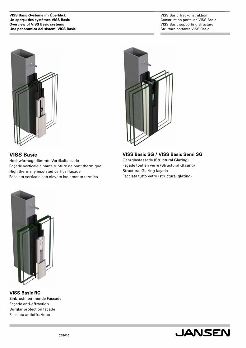
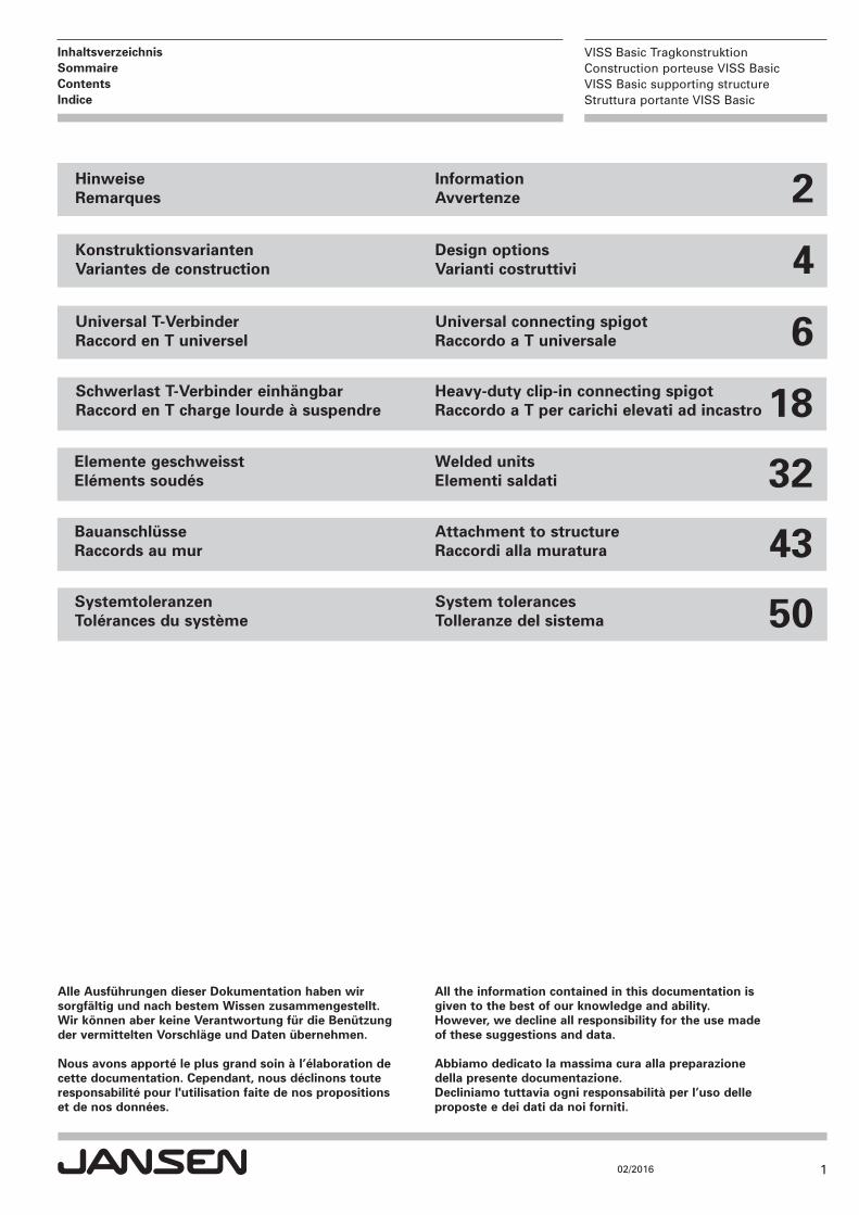
VISS Basic SG / VISS Basic Semi SGGanzglasfassade (Structural Glazing)Façade tout en verre (Structural Glazing)Structural Glazing façade Facciata tutto vetro (structural glazing)
VISS BasicHochwärmegedämmte VertikalfassadeFaçade verticale à haute rupture de pont thermiqueHigh thermally insulated vertical façade Facciata verticale con elevato isolamento termico
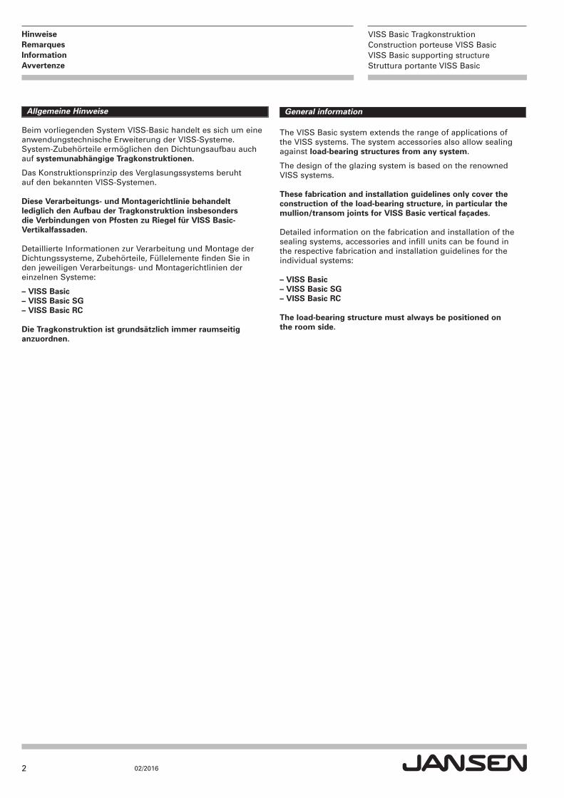
VISS Basic RCEinbruchhemmende FassadeFaçade anti-effractionBurglar protection façadeFacciata antieffrazione
VISS Basic TragkonstruktionConstruction porteuse VISS BasicVISS Basic supporting structureStruttura portante VISS Basic
02/2016
VISS Basic-Systeme im ÜberblickUn aperçu des systèmes VISS BasicOverview of VISS Basic systemsUna panoramica dei sistemi VISS Basic
1
VISS Basic TragkonstruktionConstruction porteuse VISS BasicVISS Basic supporting structureStruttura portante VISS Basic
02/2016
InhaltsverzeichnisSommaireContentsIndice
All the information contained in this documentation is given to the best of our knowledge and ability.However, we decline all responsibility for the use made of these suggestions and data.
Abbiamo dedicato la massima cura alla preparazione della presente documentazione.Decliniamo tuttavia ogni responsabilità per l’uso delle proposte e dei dati da noi forniti.
Alle Ausführungen dieser Dokumentation haben wir sorgfältig und nach bestem Wissen zusammengestellt.Wir können aber keine Verantwortung für die Benützung der vermittelten Vorschläge und Daten übernehmen.
Nous avons apporté le plus grand soin à l’élaboration de cette documentation. Cependant, nous déclinons touteresponsabilité pour l'utilisation faite de nos propositions et de nos données.
KonstruktionsvariantenVariantes de construction 4Design options
Varianti costruttivi
HinweiseRemarques 2Information
Avvertenze
18
Universal T-VerbinderRaccord en T universel
Universal connecting spigot Raccordo a T universale 6
Schwerlast T-Verbinder einhängbarRaccord en T charge lourde à suspendre
Heavy-duty clip-in connecting spigotRaccordo a T per carichi elevati ad incastro
Elemente geschweisstEléments soudés
Welded units Elementi saldati 32
Bauanschlüsse Raccords au mur
Attachment to structure Raccordi alla muratura 43
SystemtoleranzenTolérances du système
System tolerancesTolleranze del sistema 50
2
VISS Basic TragkonstruktionConstruction porteuse VISS BasicVISS Basic supporting structureStruttura portante VISS Basic
02/2016
Hinweise RemarquesInformationAvvertenze
Allgemeine Hinweise
Beim vorliegenden System VISS-Basic handelt es sich um eineanwendungstechnische Erweiterung der VISS-Systeme. System-Zubehörteile ermöglichen den Dichtungsaufbau auchauf systemunabhängige Tragkonstruktionen.
Das Konstruktionsprinzip des Verglasungssystems beruht auf den bekannten VISS-Systemen.
Diese Verarbeitungs- und Montagerichtlinie behandelt lediglich den Aufbau der Tragkonstruktion insbesonders die Verbindungen von Pfosten zu Riegel für VISS Basic-Vertikalfassaden.
Detaillierte Informationen zur Verarbeitung und Montage derDichtungssysteme, Zubehörteile, Füllelemente finden Sie in den jeweiligen Verarbeitungs- und Montagerichtlinien der einzelnen Systeme:
– VISS Basic– VISS Basic SG– VISS Basic RC
Die Tragkonstruktion ist grund sätz lich immer raumseitig anzuordnen.
General information
The VISS Basic system extends the range of applications ofthe VISS systems. The system accessories also allow sealingagainst load-bearing structures from any system.
The design of the glazing system is based on the renownedVISS systems.
These fabrication and installation guidelines only cover theconstruction of the load-bearing structure, in particular themullion/transom joints for VISS Basic vertical façades.
Detailed information on the fabrication and installation of thesealing systems, accessories and infill units can be found inthe respective fabrication and installation guidelines for theindividual systems:
– VISS Basic– VISS Basic SG– VISS Basic RC
The load-bearing structure must always be positioned on the room side.
3
VISS Basic TragkonstruktionConstruction porteuse VISS BasicVISS Basic supporting structureStruttura portante VISS Basic
02/2016
Hinweise RemarquesInformationAvvertenze
Remarques générales
Le système VISS-Basic que nous vous proposons est une extension des applications des systèmes VISS. Les accessoires du système permettent également l'étanchéification sur les constructions porteuses indépendantes d'un système.
Le principe de construction du système de vitrage repose sur les systèmes VISS connus.
Cette directive d'usinage et de montage traite uniquement du montage de la construction porteuse, en particulier des assemblages de montants et de traverses pour les façades verticales VISS Basic.
Des informations détaillées sur l'usinage et le montage des systèmes d'étanchéité, des accessoires et des éléments de remplissage sont données dans les directives d'usinage et de montage des différents systèmes:
– VISS Basic– VISS Basic SG– VISS Basic RC
La construction porteuse est toujours disposée côté intérieur.
Avvertenze generali
Il presente sistema VISS Basic costituisce un ampliamento tecnico ed applicativo dei sistemi VISS. Grazie agli accessori è possibile montare le guarnizioni anche su strutture portanti indipendenti dal sistema.
Il principio costruttivo di questo sistema di vetratura si basa sui noti sistemi VISS.
Le presenti istruzioni per la lavorazione e il montaggio si limitano a spiegare la disposizione della struttura portante, in particolare i collegamenti tra i montanti e i traversi per le facciate verticali VISS Basic.
Per informazioni dettagliate sulla lavorazione e il montaggio dei sistemi di guarnizioni, degli accessori e degli elementi di riempimento si consiglia di consultare il manuale di istruzioni per la lavorazione e il montaggio del sistema in uso:
– VISS Basic– VISS Basic SG– VISS Basic RC
Costruzione portante applicata sul lato interno.
4
VISS Basic TragkonstruktionConstruction porteuse VISS BasicVISS Basic supporting structureStruttura portante VISS Basic
02/2016
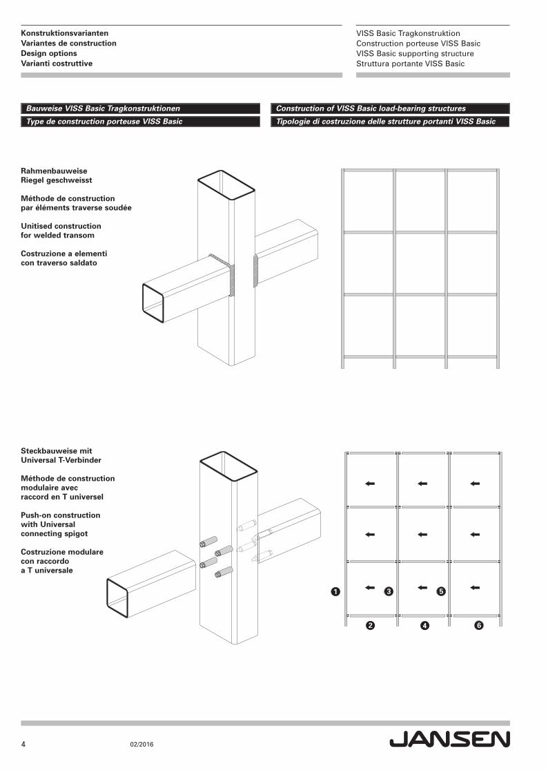
Konstruktionsvarianten Variantes de constructionDesign options Varianti costruttive
Rahmenbauweise Riegel geschweisst
Méthode de construction par éléments traverse soudée
Unitised construction for welded transom
Costruzione a elementi con traverso saldato
Steckbauweise mit Universal T-Verbinder
Méthode de construction modulaire avec raccord en T universel
Push-on construction with Universal connecting spigot
Costruzione modulare con raccordo a T universale
Construction of VISS Basic load-bearing structuresBauweise VISS Basic Tragkonstruktionen
Tipologie di costruzione delle strutture portanti VISS BasicType de construction porteuse VISS Basic
5
VISS Basic TragkonstruktionConstruction porteuse VISS BasicVISS Basic supporting structureStruttura portante VISS Basic
02/2016
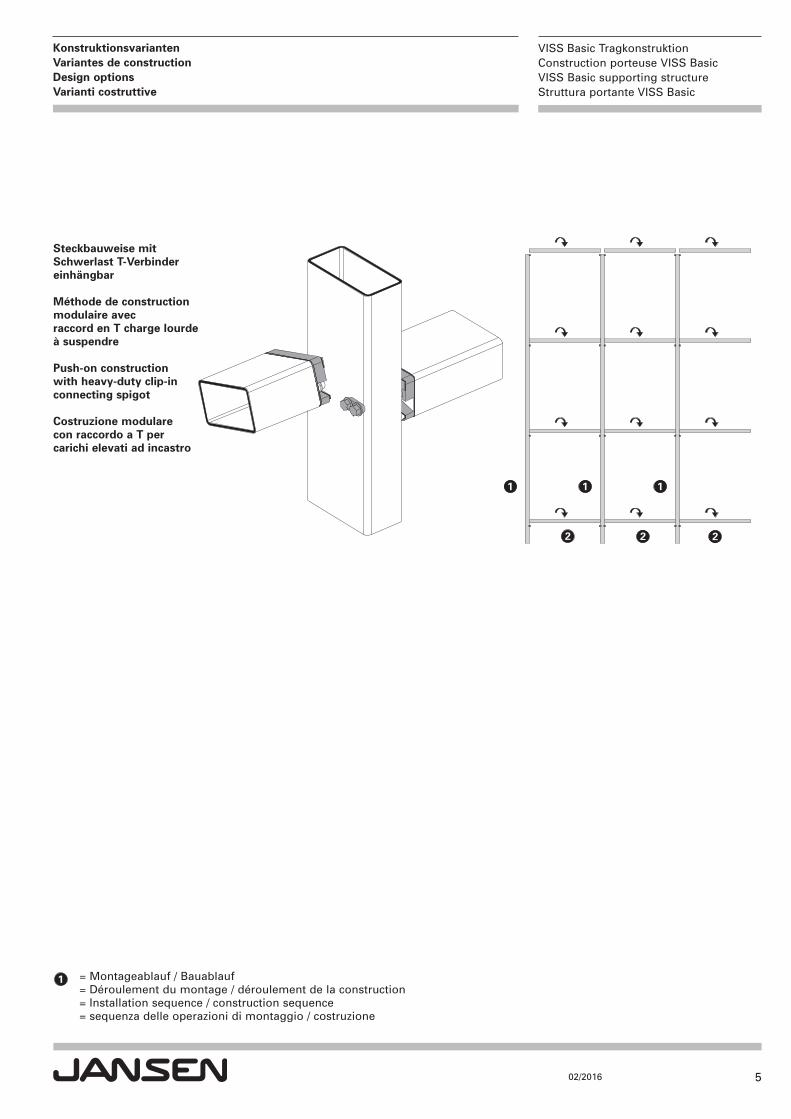
Konstruktionsvarianten Variantes de constructionDesign options Varianti costruttive
Steckbauweise mit Schwerlast T-Verbinder einhängbar
Méthode de construction modulaire avec raccord en T charge lourde à suspendre
Push-on construction with heavy-duty clip-in connecting spigot
Costruzione modulare con raccordo a T per carichi elevati ad incastro
= Montageablauf / Bauablauf= Déroulement du montage / déroulement de la construction= Installation sequence / construction sequence= sequenza delle operazioni di montaggio / costruzione

6
VISS Basic TragkonstruktionConstruction porteuse VISS BasicVISS Basic supporting structureStruttura portante VISS Basic
02/2016
Universal T-Verbinder Raccord en T universelUniversal connecting spigot Raccordo a T universale
VISS Basic SG / VISS Basic Semi SGVISS Basic
VISS Basic RC
Der Universal T-Verbinder ist bei folgenden VISS Basic Systemen einsetzbar:
The universal connecting spigot can be used in the following VISS Basic systems:
Le raccord en T universel est utilisable sur les systèmes VISS Basic suivants:
Il raccordo a T universale può essere utilizzato con i seguenti sistemi VISS Basic:
7
VISS Basic TragkonstruktionConstruction porteuse VISS BasicVISS Basic supporting structureStruttura portante VISS Basic
02/2016
Universal T-Verbinder Raccord en T universelUniversal connecting spigot Raccordo a T universale
Ablaufschritte: Tragkonstruktion mit Universal T-Verbinder
Seite
1. Konstruktionen 8
2. Verarbeitungshilfen 10
3. Füllelementgewichte / Tragfähigkeit 11
4. Verarbeitung 13
5. Oberflächenbehandlung 14
6. Bohrbild für CNC-Programmierung 16
Étapes du déroulement: Construction porteuse avec raccord en T universel
Page
1. Constructions 8
2. Outils d'usinage 10
3. Poids de remplissage / charge admissible 11
4. Usinage 13
5. Traitement de surface 14
6. Schéma de perçage pour programmation CNC 16
Process steps: Load-bearing structure with universal connecting spigot
Page
1. Constructions 8
2. Assembly tools 10
3. Infill unit weights/load-bearing capacity 11
4. Processing 13
5. Surface treatment 14
6. Drilling pattern for CNC programming 16
Sequenza delle operazioni: Costruzione portante con raccordo a T universale
Pagina
1. Tipologie di costruzione 8
2. Attrezzatura per il montaggio 10
3. Pesi degli elementi di riempimento / capacità portante 11
4. Lavorazione 13
5. Trattamento superficiale 14
6. Piano di foratura per la programmazione CNC 16
Einsatzbereich:Tragkonstruktion raumseitig angeordnet. Nur für Innenbereiche trocken, ohne Feuchtigkeitsbelastung.
Domaine d'utilisation:Construction porteuse disposée côté intérieur. Uniquement pour utilisation en intérieur à sec, sans humidité.
Area of application:Load-bearing structure arranged on the room side. For internal use in dry areas only, with no moisture.
Campo di impiego:Costruzione portante applicata sul lato interno. Solo per ambienti asciutti, senza umidità.
8
VISS Basic TragkonstruktionConstruction porteuse VISS BasicVISS Basic supporting structureStruttura portante VISS Basic
02/2016
Universal T-Verbinder Raccord en T universelUniversal connecting spigot Raccordo a T universale
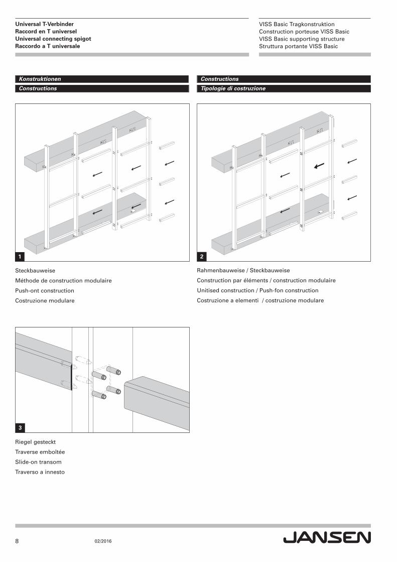
ConstructionsKonstruktionen
Tipologie di costruzioneConstructions
Steckbauweise
Méthode de construction modulaire
Push-ont construction
Costruzione modulare
Rahmenbauweise / Steckbauweise
Construction par éléments / construction modulaire
Unitised construction / Push-fon construction
Costruzione a elementi / costruzione modulare
Riegel gesteckt
Traverse emboîtée
Slide-on transom
Traverso a innesto
1 2
3
9
VISS Basic TragkonstruktionConstruction porteuse VISS BasicVISS Basic supporting structureStruttura portante VISS Basic
02/2016
Universal T-Verbinder Raccord en T universelUniversal connecting spigot Raccordo a T universale
�Ri ≤ 5 mm
�Ra ≤ tR
t R
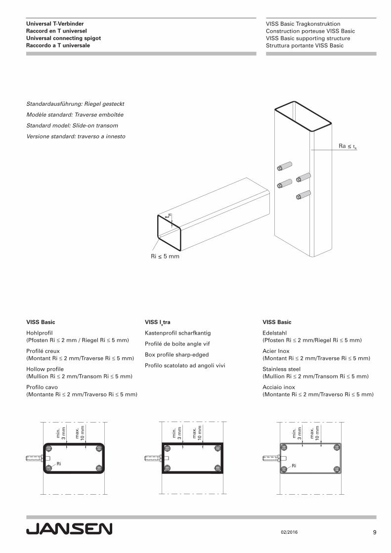
Standardausführung: Riegel gesteckt
Modèle standard: Traverse emboîtée
Standard model: Slide-on transom
Versione standard: traverso a innesto
max
.10
mm
min
.3
mm
Ri
min
.3
mm
max
.10
mm
min
.3
mm
max
.10
mm
Ri
VISS Basic
Edelstahl(Pfosten Ri ≤ 2 mm/Riegel Ri ≤ 5 mm)
Acier Inox(Montant Ri ≤ 2 mm/Traverse Ri ≤ 5 mm)
Stainless steel(Mullion Ri ≤ 2 mm/Transom Ri ≤ 5 mm)
Acciaio inox(Montante Ri ≤ 2 mm/Traverso Ri ≤ 5 mm)
VISS Ixtra
Kastenprofil scharfkantig
Profilé de boîte angle vif
Box profile sharp-edged
Profilo scatolato ad angoli vivi
VISS Basic
Hohlprofil(Pfosten Ri ≤ 2 mm / Riegel Ri ≤ 5 mm)
Profilé creux(Montant Ri ≤ 2 mm/Traverse Ri ≤ 5 mm)
Hollow profile(Mullion Ri ≤ 2 mm/Transom Ri ≤ 5 mm)
Profilo cavo (Montante Ri ≤ 2 mm/Traverso Ri ≤ 5 mm)
10
VISS Basic TragkonstruktionConstruction porteuse VISS BasicVISS Basic supporting structureStruttura portante VISS Basic
02/2016
Universal T-Verbinder Raccord en T universelUniversal connecting spigot Raccordo a T universale
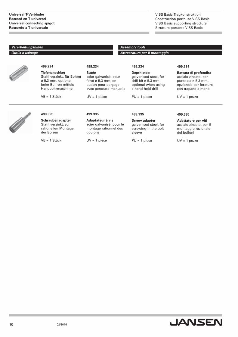
499.395
SchraubenadapterStahl verzinkt, zur rationellen Montage der Bolzen
VE = 1 Stück
499.395
Adaptateur à visacier galvanisé, pour le montage rationnel desgoujons
UV = 1 pièce
499.395
Screw adaptergalvanised steel, for screwing-in the bolt sleeve
PU = 1 piece
499.234
TiefenanschlagStahl verzinkt, für Bohrer ø 5,3 mm, optional beim Bohren mittelsHandbohrmaschine
VE = 1 Stück
499.234
Butéeacier galvanisé, pour foret ø 5,3 mm, en option pour perçage avec perceuse manuelle
UV = 1 pièce
499.234
Depth stopgalvanised steel, for drill bit ø 5.3 mm, optional when using a hand-held drill
PU = 1 piece
Assembly tools Verarbeitungshilfen
Attrezzatura per il montaggio Outils d’usinage
499.395
Adattatore per vitiacciaio zincato, per ilmontaggio razionale dei bulloni
UV = 1 pezzo
499.234
Battuta di profonditàacciaio zincato, per punte da ø 5,3 mm,opzionale per foraturacon trapano a mano
UV = 1 pezzo
11
VISS Basic TragkonstruktionConstruction porteuse VISS BasicVISS Basic supporting structureStruttura portante VISS Basic
02/2016
Universal T-Verbinder Raccord en T universelUniversal connecting spigot Raccordo a T universale
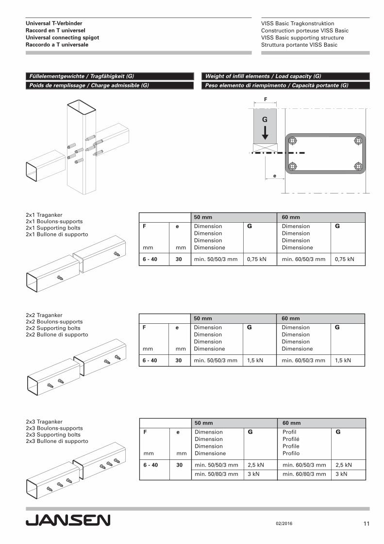
2x1 Traganker2x1 Boulons-supports2x1 Supporting bolts2x1 Bullone di supporto
2x2 Traganker2x2 Boulons-supports2x2 Supporting bolts2x2 Bullone di supporto
2x3 Traganker2x3 Boulons-supports2x3 Supporting bolts2x3 Bullone di supporto
Weight of infill elements / Load capacity (G)Füllelementgewichte / Tragfähigkeit (G)
Peso elemento di riempimento / Capacità portante (G)Poids de remplissage / Charge admissible (G)
50 mm 60 mm
F e Dimension G Dimension G Dimension Dimension Dimension Dimension
mm mm Dimensione Dimensione
6 - 40 30 min. 50/50/3 mm 0,75 kN min. 60/50/3 mm 0,75 kN
50 mm 60 mm
F e Dimension G Dimension G Dimension Dimension Dimension Dimension
mm mm Dimensione Dimensione
6 - 40 30 min. 50/50/3 mm 1,5 kN min. 60/50/3 mm 1,5 kN
50 mm 60 mm
F e Dimension G Profil G Dimension Profilé Dimension Profile
mm mm Dimensione Profilo
6 - 40 30 min. 50/50/3 mm 2,5 kN min. 60/50/3 mm 2,5 kN
min. 50/80/3 mm 3 kN min. 60/80/3 mm 3 kN
G
e
F
12
VISS Basic TragkonstruktionConstruction porteuse VISS BasicVISS Basic supporting structureStruttura portante VISS Basic
02/2016
Universal T-Verbinder Raccord en T universelUniversal connecting spigot Raccordo a T universale
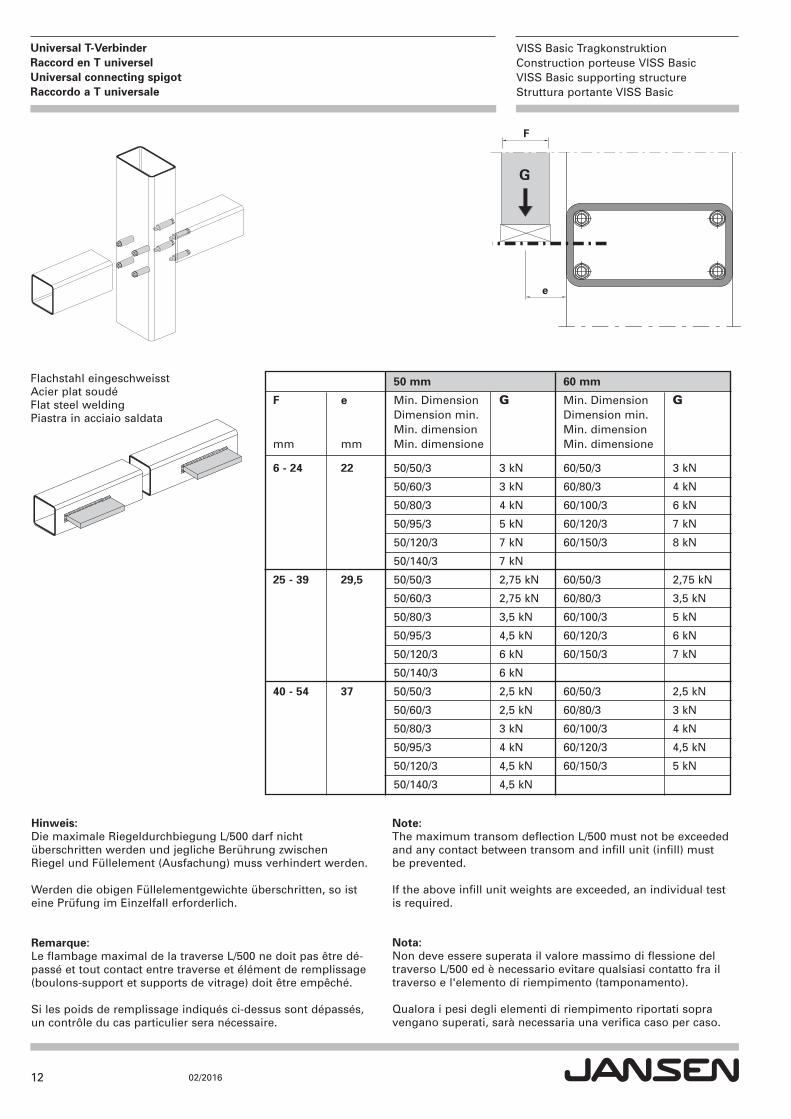
Flachstahl eingeschweisstAcier plat soudéFlat steel weldingPiastra in acciaio saldata
G
e
F
50 mm 60 mm
F e Min. Dimension G Min. Dimension G Dimension min. Dimension min. Min. dimension Min. dimension mm mm Min. dimensione Min. dimensione
6 - 24 22 50/50/3 3 kN 60/50/3 3 kN
50/60/3 3 kN 60/80/3 4 kN
50/80/3 4 kN 60/100/3 6 kN
50/95/3 5 kN 60/120/3 7 kN
50/120/3 7 kN 60/150/3 8 kN
50/140/3 7 kN
25 - 39 29,5 50/50/3 2,75 kN 60/50/3 2,75 kN
50/60/3 2,75 kN 60/80/3 3,5 kN
50/80/3 3,5 kN 60/100/3 5 kN
50/95/3 4,5 kN 60/120/3 6 kN
50/120/3 6 kN 60/150/3 7 kN
50/140/3 6 kN
40 - 54 37 50/50/3 2,5 kN 60/50/3 2,5 kN
50/60/3 2,5 kN 60/80/3 3 kN
50/80/3 3 kN 60/100/3 4 kN
50/95/3 4 kN 60/120/3 4,5 kN
50/120/3 4,5 kN 60/150/3 5 kN
50/140/3 4,5 kN
Hinweis:Die maximale Riegeldurchbiegung L/500 darf nicht überschritten werden und jegliche Berührung zwischen Riegel und Füllelement (Ausfachung) muss verhindert werden.
Werden die obigen Füllelementgewichte überschritten, so isteine Prüfung im Einzelfall erforderlich.
Remarque:Le flambage maximal de la traverse L/500 ne doit pas être dé-passé et tout contact entre traverse et élément de remplissage(boulons-support et supports de vitrage) doit être empêché.
Si les poids de remplissage indiqués ci-dessus sont dépassés,un contrôle du cas particulier sera nécessaire.
Note:The maximum transom deflection L/500 must not be exceededand any contact between transom and infill unit (infill) mustbe prevented.
If the above infill unit weights are exceeded, an individual testis required.
Nota:Non deve essere superata il valore massimo di flessione deltraverso L/500 ed è necessario evitare qualsiasi contatto fra iltraverso e l'elemento di riempimento (tamponamento).
Qualora i pesi degli elementi di riempimento riportati sopravengano superati, sarà necessaria una verifica caso per caso.
13
VISS Basic TragkonstruktionConstruction porteuse VISS BasicVISS Basic supporting structureStruttura portante VISS Basic
02/2016
Universal T-Verbinder Raccord en T universelUniversal connecting spigot Raccordo a T universale
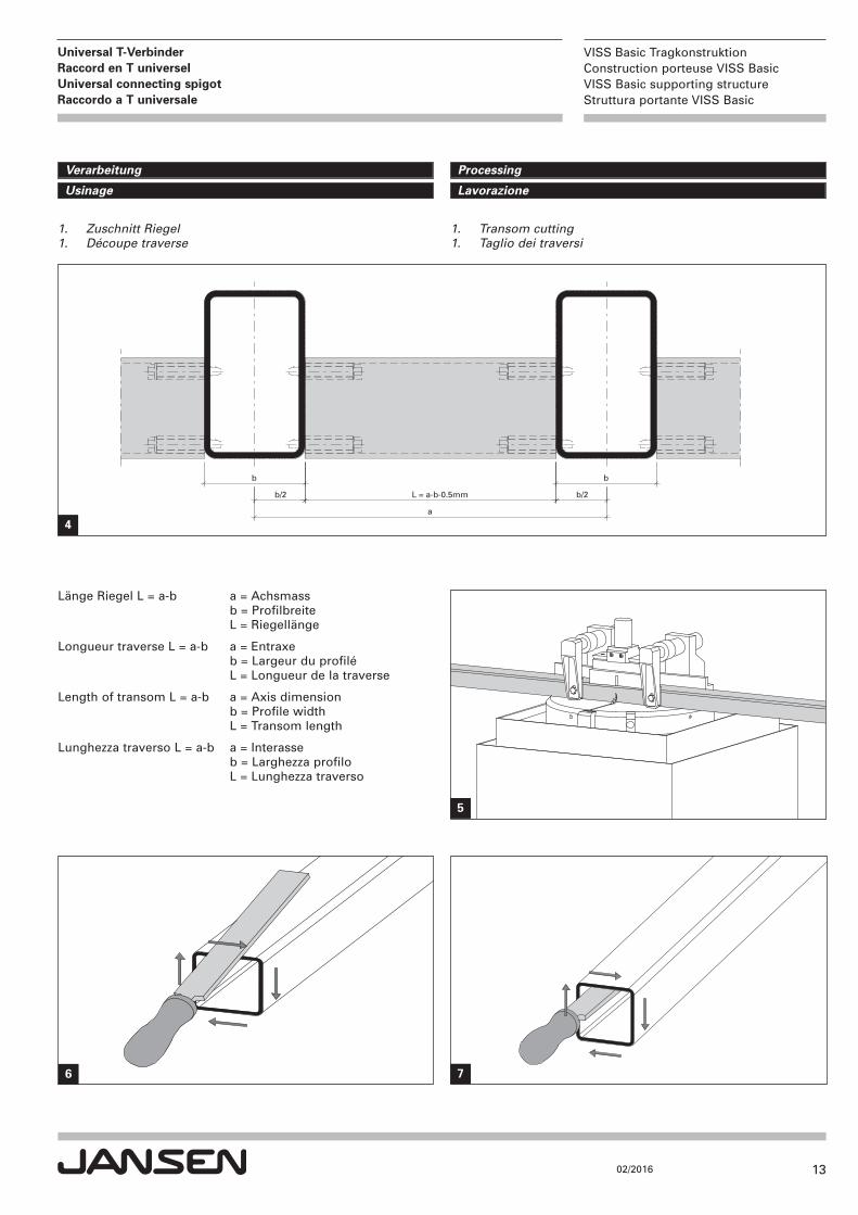
b b
b/2b/2
a
L = a-b-0.5mm
Länge Riegel L = a-b a = Achsmass b = Profilbreite L = Riegellänge
Longueur traverse L = a-b a = Entraxe b = Largeur du profilé L = Longueur de la traverse
Length of transom L = a-b a = Axis dimension b = Profile width L = Transom length
Lunghezza traverso L = a-b a = Interasse b = Larghezza profilo L = Lunghezza traverso
1. Transom cutting 1. Taglio dei traversi
1. Zuschnitt Riegel 1. Découpe traverse
4
76
5
ProcessingVerarbeitung
LavorazioneUsinage
14
VISS Basic TragkonstruktionConstruction porteuse VISS BasicVISS Basic supporting structureStruttura portante VISS Basic
02/2016
Universal T-Verbinder Raccord en T universelUniversal connecting spigot Raccordo a T universale
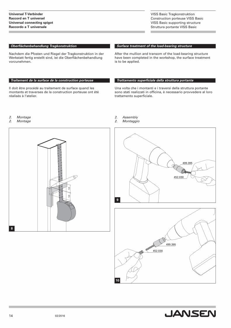
Oberflächenbehandlung Tragkonstruktion
Nachdem die Pfosten und Riegel der Tragkonstruktion in der Werkstatt fertig erstellt sind, ist die Oberflächenbehandlung vorzunehmen.
Surface treatment of the load-bearing structure
After the mullion and transom of the load-bearing structure have been completed in the workshop, the surface treatment is to be applied.
Traitement de la surface de la construction porteuse
Il doit être procédé au traitement de surface quand les montants et traverses de la construction porteuse ont été réalisés à l'atelier.
Trattamento superficiale della struttura portante
Una volta che i montanti e i traversi della struttura portante sono stati realizzati in officina, è necessario provvedere al loro trattamento superficiale.
2. Assembly 2. Montaggio
2. Montage 2. Montage
452.030
499.395
499.395
452.030
9
1/2
1/2
8
10
15
VISS Basic TragkonstruktionConstruction porteuse VISS BasicVISS Basic supporting structureStruttura portante VISS Basic
02/2016
Universal T-Verbinder Raccord en T universelUniversal connecting spigot Raccordo a T universale
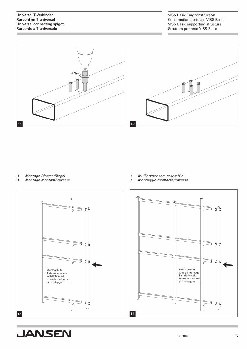
4 Nm
11 12
MontagehilfeAide au montageInstallation aidUtensile ausiliario di montaggio
MontagehilfeAide au montageInstallation aidUtensile ausiliario di montaggio
3. Mullion/transom assembly 3. Montaggio montante/traverso
3. Montage Pfosten/Riegel 3. Montage montant/traverse
13 14
16
VISS Basic TragkonstruktionConstruction porteuse VISS BasicVISS Basic supporting structureStruttura portante VISS Basic
02/2016
Universal T-Verbinder Raccord en T universelUniversal connecting spigot Raccordo a T universale
b/2
-t-5
.2b
/2-t
-5.2
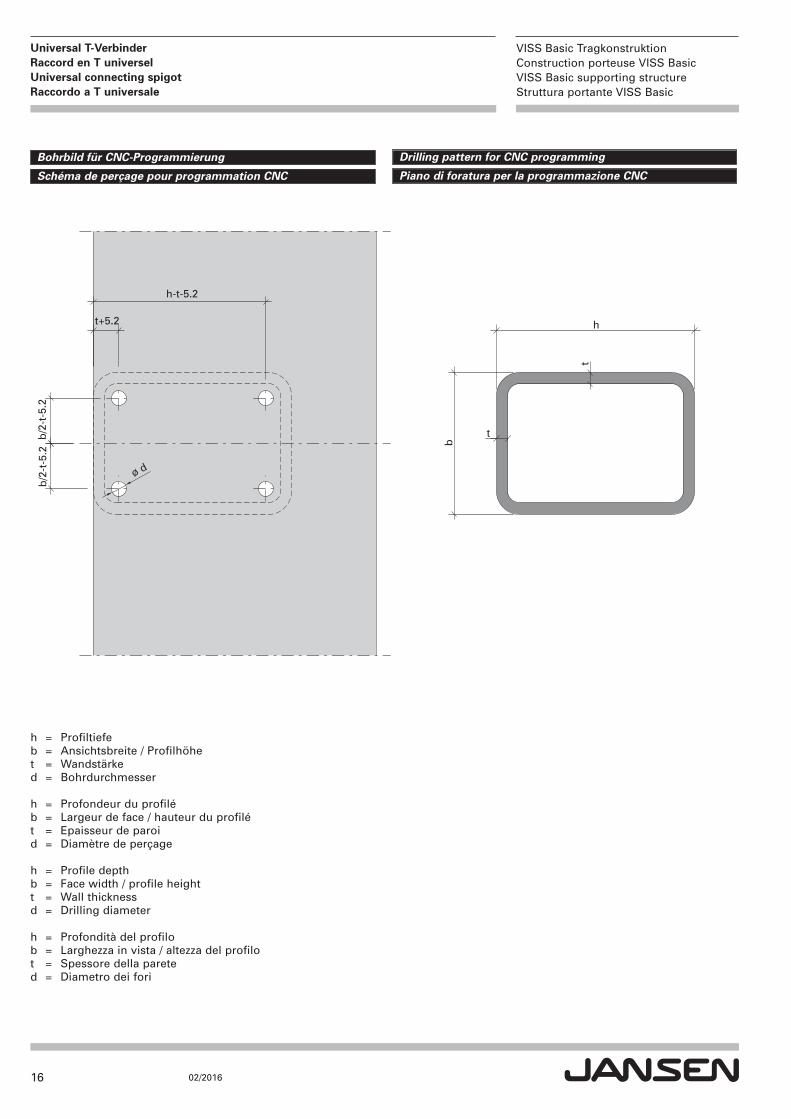
t+5.2
h-t-5.2
b
t
t
h
ø d
Drilling pattern for CNC programmingBohrbild für CNC-Programmierung
Piano di foratura per la programmazione CNCSchéma de perçage pour programmation CNC
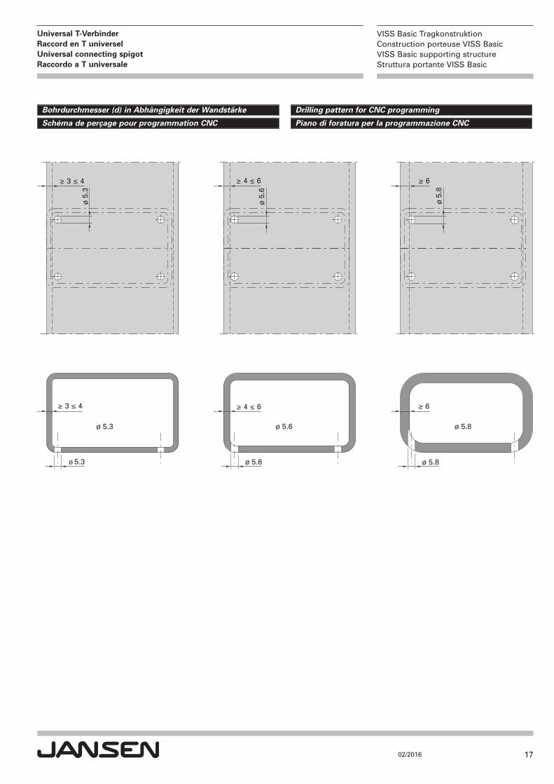
h = Profiltiefeb = Ansichtsbreite / Profilhöhet = Wandstärked = Bohrdurchmesser
h = Profondeur du profiléb = Largeur de face / hauteur du profilét = Epaisseur de paroid = Diamètre de perçage
h = Profile depthb = Face width / profile heightt = Wall thicknessd = Drilling diameter
h = Profondità del profilob = Larghezza in vista / altezza del profilot = Spessore della pareted = Diametro dei fori
17
VISS Basic TragkonstruktionConstruction porteuse VISS BasicVISS Basic supporting structureStruttura portante VISS Basic
02/2016
Universal T-Verbinder Raccord en T universelUniversal connecting spigot Raccordo a T universale
Drilling pattern for CNC programmingBohrdurchmesser (d) in Abhängigkeit der Wandstärke
Piano di foratura per la programmazione CNCSchéma de perçage pour programmation CNC
ø 5.3 ø 5.6 ø 5.8
≥ 3 ≤ 4
≥ 3 ≤ 4
≥ 4 ≤ 6
≥ 4 ≤ 6
≥ 6
≥ 6
ø 5
.3
ø 5
.6
ø 5
.8
ø 5.3 ø 5.6 ø 5.8
18
VISS Basic TragkonstruktionConstruction porteuse VISS BasicVISS Basic supporting structureStruttura portante VISS Basic
02/2016
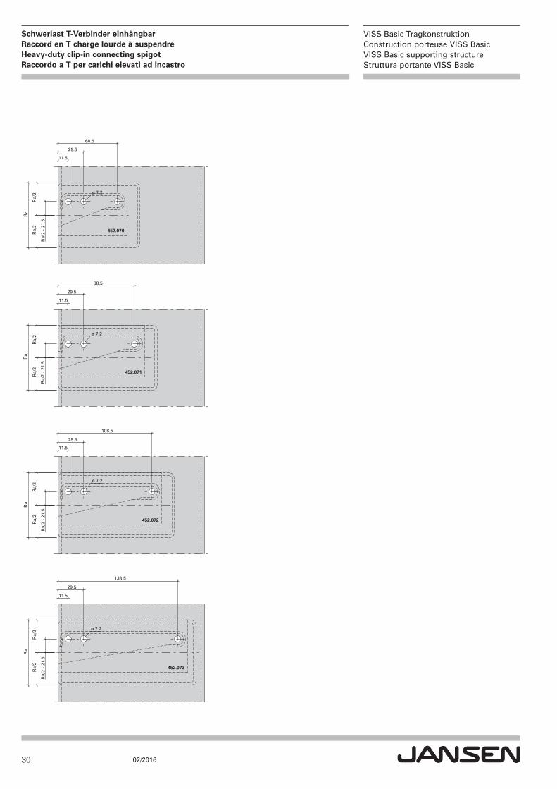
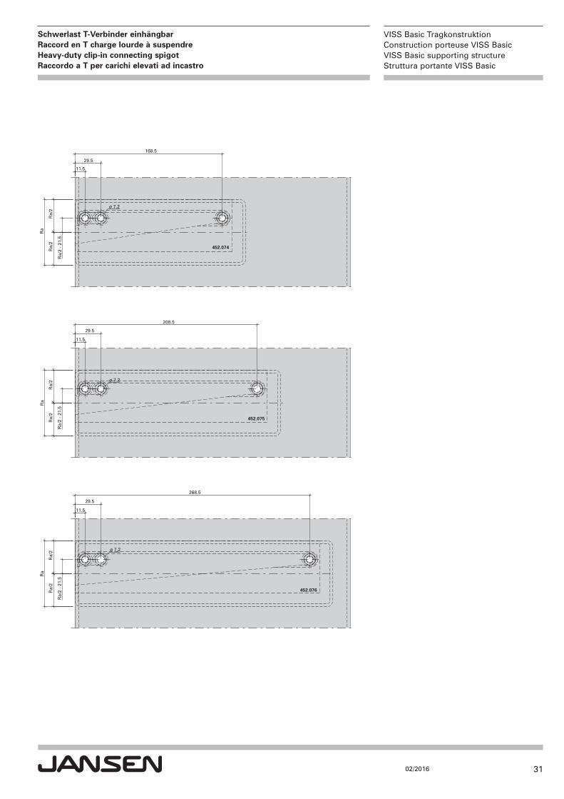
Schwerlast T-Verbinder einhängbarRaccord en T charge lourde à suspendreHeavy-duty clip-in connecting spigot Raccordo a T per carichi elevati ad incastro
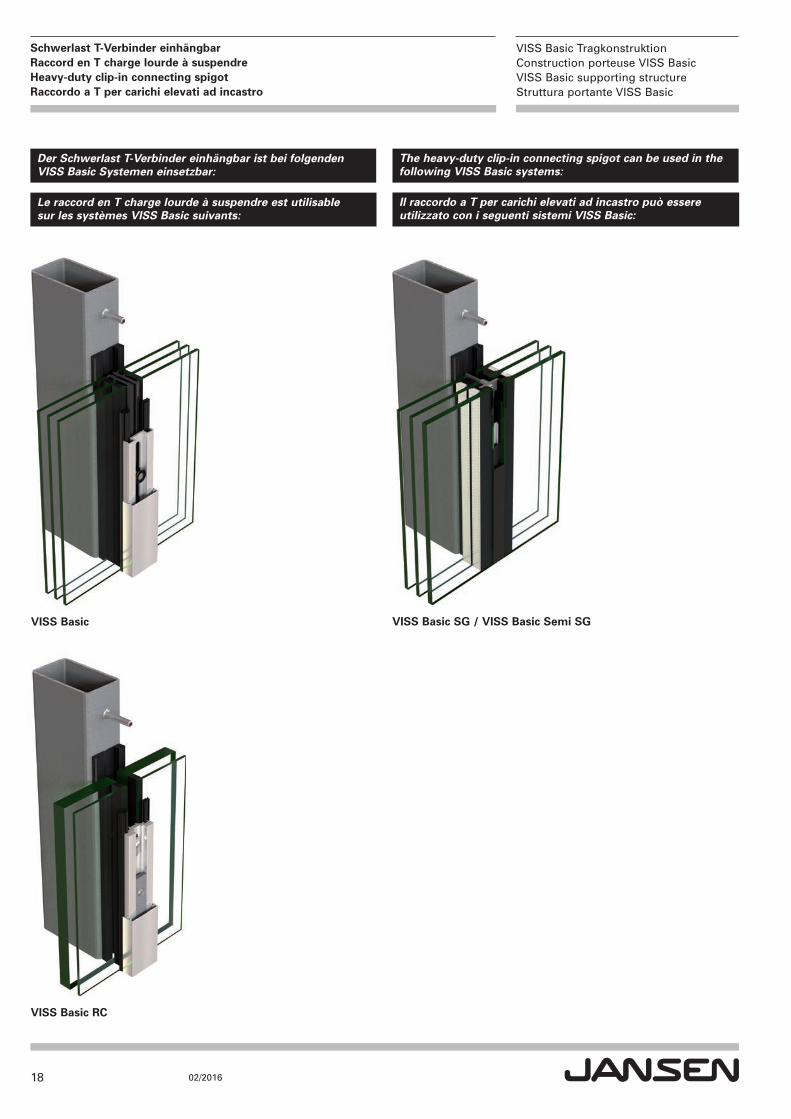
Der Schwerlast T-Verbinder einhängbar ist bei folgenden VISS Basic Systemen einsetzbar:
The heavy-duty clip-in connecting spigot can be used in the following VISS Basic systems:
Le raccord en T charge lourde à suspendre est utilisablesur les systèmes VISS Basic suivants:
Il raccordo a T per carichi elevati ad incastro può essere utilizzato con i seguenti sistemi VISS Basic:
VISS Basic SG / VISS Basic Semi SGVISS Basic
VISS Basic RC
19
VISS Basic TragkonstruktionConstruction porteuse VISS BasicVISS Basic supporting structureStruttura portante VISS Basic
02/2016
Schwerlast T-Verbinder einhängbarRaccord en T charge lourde à suspendreHeavy-duty clip-in connecting spigot Raccordo a T per carichi elevati ad incastro
Ablaufschritte: Tragkonstruktion mit Schwerlast T-Verbinder einhängbar
Seite
1. Konstruktionen 20
2. Verarbeitungshilfen 21
3. Füllelementgewichte / Tragfähigkeit 22
4. Verarbeitung 24
5. Oberflächenbehandlung 26
6. Bohrbild für CNC-Programmierung 29
Étapes du déroulement: Construction porteuse avec raccord en T charge lourde à suspendre
Page
1. Constructions 20
2. Outils d'usinage 21
3. Poids de remplissage / charge admissible 22
4. Usinage 24
5. Traitement de surface 26
6. Schéma de perçage pour programmation CNC 29
Process steps: Load-bearing structure with heavy-duty clip-in connecting spigot
Page
1. Constructions 20
2. Assembly tools 21
3. Infill unit weights/load-bearing capacity 22
4. Processing 24
5. Surface treatment 26
6. Drilling pattern for CNC programming 29
Sequenza delle operazioni: Struttura portante con raccordo a T per carichi elevati ad incastro
Pagina
1. Tipologie di costruzione 20
2. Attrezzatura per il montaggio 21
3. Pesi degli elementi di riempimento / capacità portante 22
4. Lavorazione 24
5. Trattamento superficiale 26
6. Piano di foratura per la programmazione CNC 29
Einsatzbereich:Tragkonstruktion raumseitig angeordnet. Nur für Innenbereiche trocken, ohne Feuchtigkeitsbelastung.
Domaine d'utilisation:Construction porteuse disposée côté intérieur. Uniquement pour utilisation en intérieur à sec, sans humidité.
Area of application:Load-bearing structure arranged on the room side. For internal use in dry areas only, with no moisture.
Campo di impiego:Costruzione portante applicata sul lato interno. Solo per ambienti asciutti, senza umidità.
20
VISS Basic TragkonstruktionConstruction porteuse VISS BasicVISS Basic supporting structureStruttura portante VISS Basic
02/2016
Schwerlast T-Verbinder einhängbarRaccord en T charge lourde à suspendreHeavy-duty clip-in connecting spigot Raccordo a T per carichi elevati ad incastro
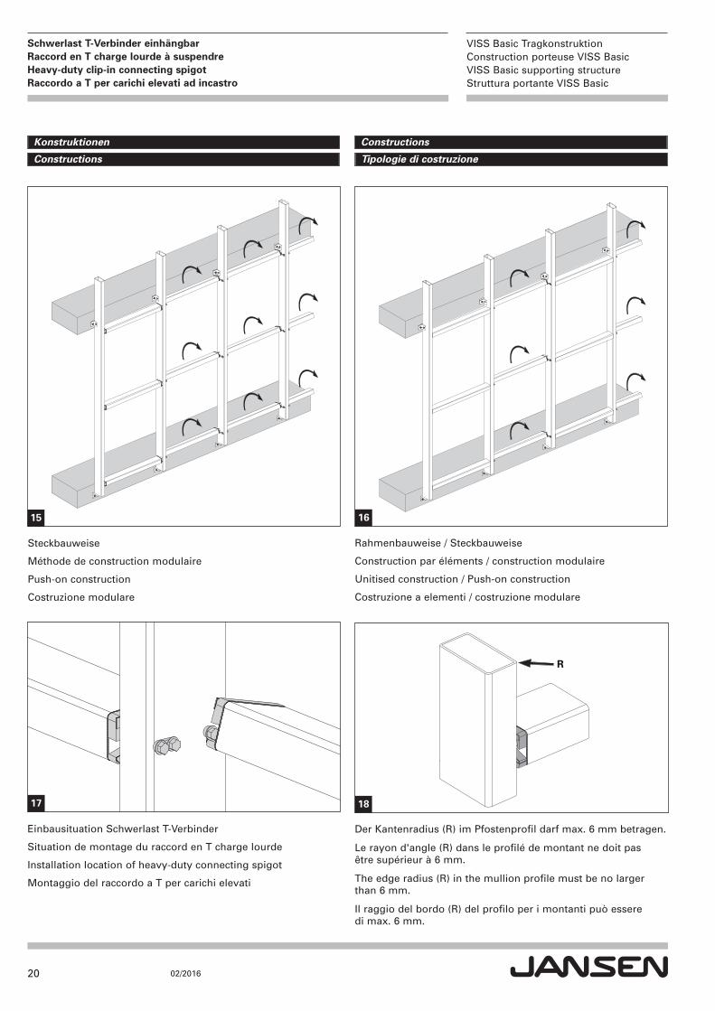
Steckbauweise
Méthode de construction modulaire
Push-on construction
Costruzione modulare
Einbausituation Schwerlast T-Verbinder
Situation de montage du raccord en T charge lourde
Installation location of heavy-duty connecting spigot
Montaggio del raccordo a T per carichi elevati
ConstructionsKonstruktionen
Tipologie di costruzioneConstructions
15
Rahmenbauweise / Steckbauweise
Construction par éléments / construction modulaire
Unitised construction / Push-on construction
Costruzione a elementi / costruzione modulare
16
17
R
18
Der Kantenradius (R) im Pfostenprofil darf max. 6 mm betragen.
Le rayon d'angle (R) dans le profilé de montant ne doit pas être supérieur à 6 mm.
The edge radius (R) in the mullion profile must be no largerthan 6 mm.
Il raggio del bordo (R) del profilo per i montanti può essere di max. 6 mm.
21
VISS Basic TragkonstruktionConstruction porteuse VISS BasicVISS Basic supporting structureStruttura portante VISS Basic
02/2016
Schwerlast T-Verbinder einhängbarRaccord en T charge lourde à suspendreHeavy-duty clip-in connecting spigot Raccordo a T per carichi elevati ad incastro
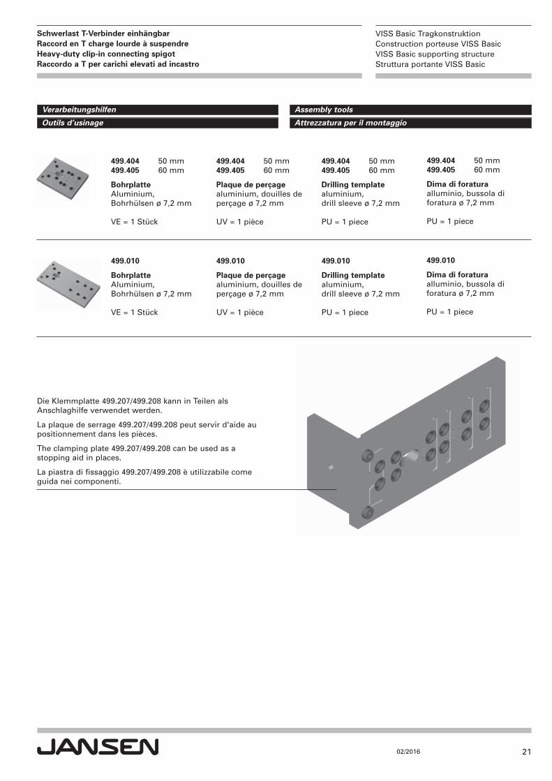
499.404 50 mm499.405 60 mm
BohrplatteAluminium, Bohrhülsen ø 7,2 mm
VE = 1 Stück
499.404 50 mm499.405 60 mm
Plaque de perçagealuminium, douilles deperçage ø 7,2 mm
UV = 1 pièce
499.404 50 mm499.405 60 mm
Drilling templatealuminium, drill sleeve ø 7,2 mm
PU = 1 piece
Assembly tools Verarbeitungshilfen
Attrezzatura per il montaggio Outils d’usinage
499.404 50 mm499.405 60 mm
Dima di foraturaalluminio, bussola diforatura ø 7,2 mm
PU = 1 piece
499.010
BohrplatteAluminium, Bohrhülsen ø 7,2 mm
VE = 1 Stück
499.010
Plaque de perçagealuminium, douilles deperçage ø 7,2 mm
UV = 1 pièce
499.010
Drilling templatealuminium, drill sleeve ø 7,2 mm
PU = 1 piece
499.010
Dima di foraturaalluminio, bussola diforatura ø 7,2 mm
PU = 1 piece
Die Klemmplatte 499.207/499.208 kann in Teilen alsAnschlaghilfe verwendet werden.
La plaque de serrage 499.207/499.208 peut servir d'aide au positionnement dans les pièces.
The clamping plate 499.207/499.208 can be used as a stopping aid in places.
La piastra di fissaggio 499.207/499.208 è utilizzabile come guida nei componenti.
22
VISS Basic TragkonstruktionConstruction porteuse VISS BasicVISS Basic supporting structureStruttura portante VISS Basic
02/2016
Schwerlast T-Verbinder einhängbarRaccord en T charge lourde à suspendreHeavy-duty clip-in connecting spigot Raccordo a T per carichi elevati ad incastro
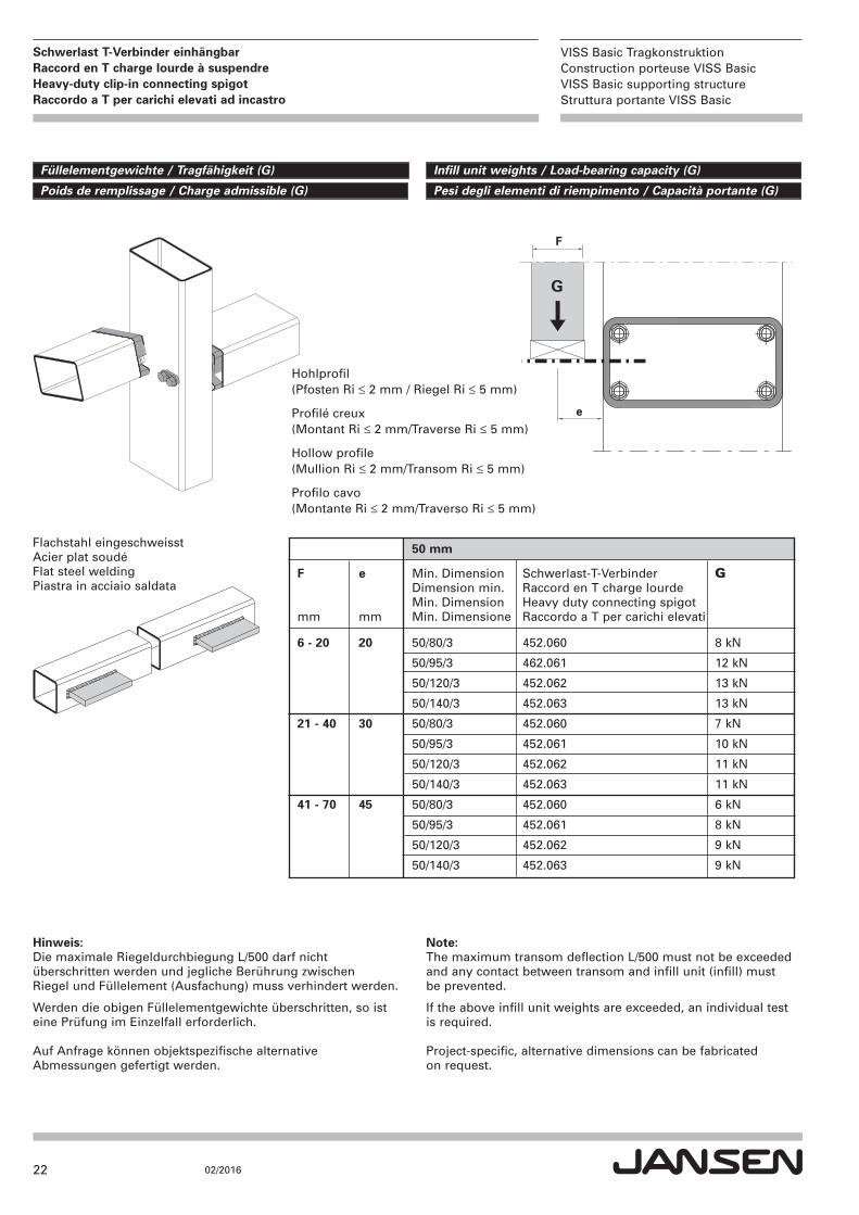
50 mm
F e Min. Dimension Schwerlast-T-Verbinder G Dimension min. Raccord en T charge lourde Min. Dimension Heavy duty connecting spigot
mm mm Min. Dimensione Raccordo a T per carichi elevati
6 - 20 20 50/80/3 452.060 8 kN
50/95/3 462.061 12 kN
50/120/3 452.062 13 kN
50/140/3 452.063 13 kN
21 - 40 30 50/80/3 452.060 7 kN
50/95/3 452.061 10 kN
50/120/3 452.062 11 kN
50/140/3 452.063 11 kN
41 - 70 45 50/80/3 452.060 6 kN
50/95/3 452.061 8 kN
50/120/3 452.062 9 kN
50/140/3 452.063 9 kN
G
e
F
Flachstahl eingeschweisstAcier plat soudéFlat steel weldingPiastra in acciaio saldata
Infill unit weights / Load-bearing capacity (G)Füllelementgewichte / Tragfähigkeit (G)
Pesi degli elementi di riempimento / Capacità portante (G)Poids de remplissage / Charge admissible (G)
Hinweis:Die maximale Riegeldurchbiegung L/500 darf nicht überschritten werden und jegliche Berührung zwischen Riegel und Füllelement (Ausfachung) muss verhindert werden.
Werden die obigen Füllelementgewichte überschritten, so isteine Prüfung im Einzelfall erforderlich.
Auf Anfrage können objektspezifische alternativeAbmessungen gefertigt werden.
Note:The maximum transom deflection L/500 must not be exceededand any contact between transom and infill unit (infill) mustbe prevented.
If the above infill unit weights are exceeded, an individual testis required.
Project-specific, alternative dimensions can be fabricated on request.
Hohlprofil(Pfosten Ri ≤ 2 mm / Riegel Ri ≤ 5 mm)
Profilé creux(Montant Ri ≤ 2 mm/Traverse Ri ≤ 5 mm)
Hollow profile(Mullion Ri ≤ 2 mm/Transom Ri ≤ 5 mm)
Profilo cavo (Montante Ri ≤ 2 mm/Traverso Ri ≤ 5 mm)
23
VISS Basic TragkonstruktionConstruction porteuse VISS BasicVISS Basic supporting structureStruttura portante VISS Basic
02/2016
Schwerlast T-Verbinder einhängbarRaccord en T charge lourde à suspendreHeavy-duty clip-in connecting spigot Raccordo a T per carichi elevati ad incastro
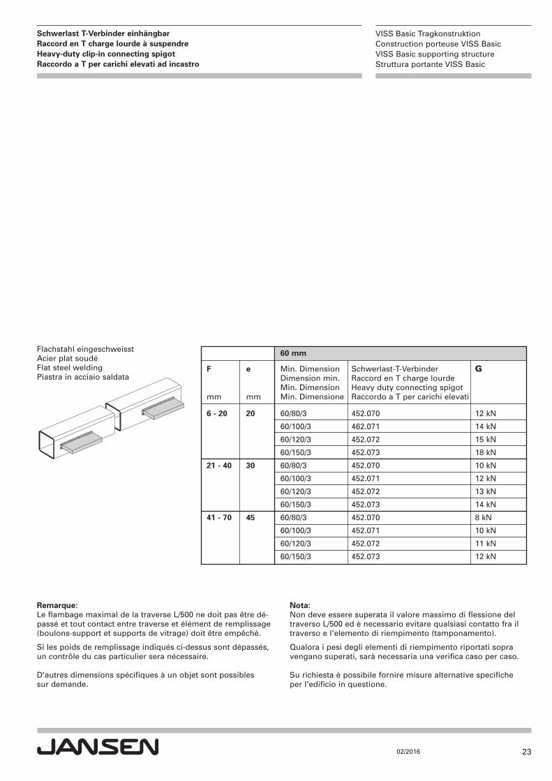
60 mm
F e Min. Dimension Schwerlast-T-Verbinder G Dimension min. Raccord en T charge lourde Min. Dimension Heavy duty connecting spigot
mm mm Min. Dimensione Raccordo a T per carichi elevati
6 - 20 20 60/80/3 452.070 12 kN
60/100/3 462.071 14 kN
60/120/3 452.072 15 kN
60/150/3 452.073 18 kN
21 - 40 30 60/80/3 452.070 10 kN
60/100/3 452.071 12 kN
60/120/3 452.072 13 kN
60/150/3 452.073 14 kN
41 - 70 45 60/80/3 452.070 8 kN
60/100/3 452.071 10 kN
60/120/3 452.072 11 kN
60/150/3 452.073 12 kN
Flachstahl eingeschweisstAcier plat soudéFlat steel weldingPiastra in acciaio saldata
Remarque:Le flambage maximal de la traverse L/500 ne doit pas être dé-passé et tout contact entre traverse et élément de remplissage(boulons-support et supports de vitrage) doit être empêché.
Si les poids de remplissage indiqués ci-dessus sont dépassés,un contrôle du cas particulier sera nécessaire.
D'autres dimensions spécifiques à un objet sont possibles sur demande.
Nota:Non deve essere superata il valore massimo di flessione deltraverso L/500 ed è necessario evitare qualsiasi contatto fra iltraverso e l'elemento di riempimento (tamponamento).
Qualora i pesi degli elementi di riempimento riportati sopravengano superati, sarà necessaria una verifica caso per caso.
Su richiesta è possibile fornire misure alternative specificheper l'edificio in questione.
24
VISS Basic TragkonstruktionConstruction porteuse VISS BasicVISS Basic supporting structureStruttura portante VISS Basic
02/2016
Schwerlast T-Verbinder einhängbarRaccord en T charge lourde à suspendreHeavy-duty clip-in connecting spigot Raccordo a T per carichi elevati ad incastro
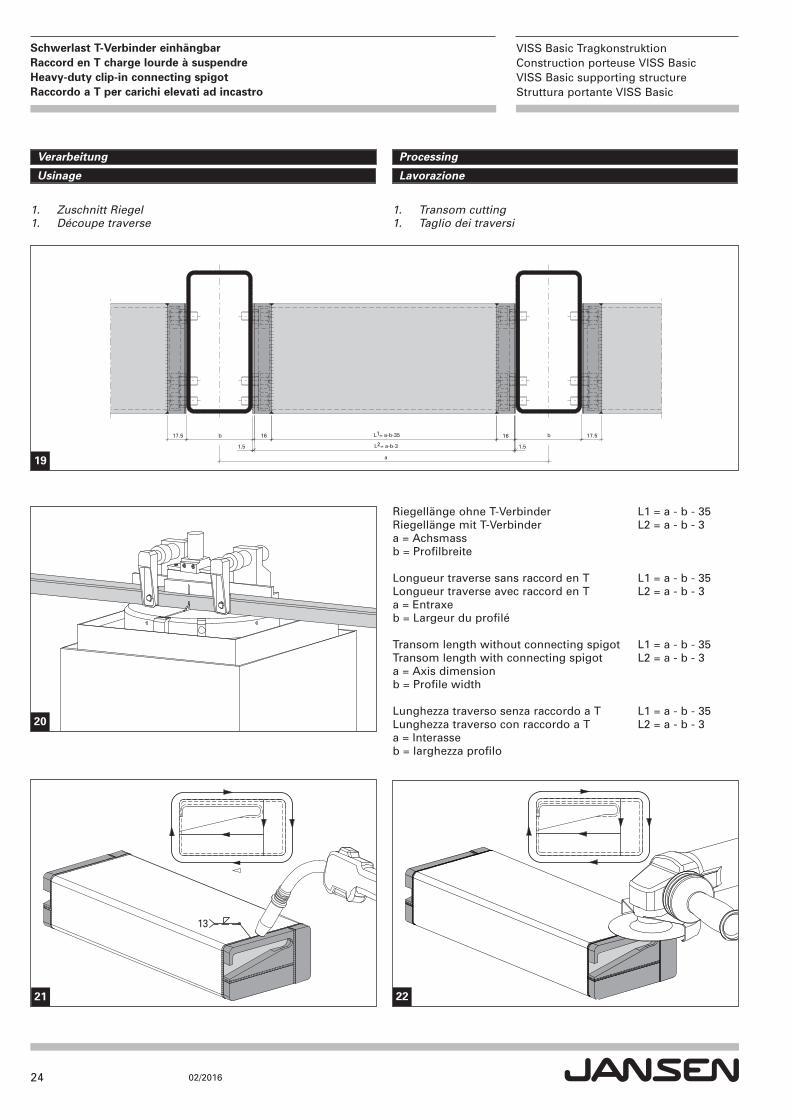
17.5 b 17.5L1 = a-b-35
a
b
1.5
16 16
1.5L2 = a-b-3
Riegellänge ohne T-Verbinder L1 = a - b - 35Riegellänge mit T-Verbinder L2 = a - b - 3a = Achsmassb = Profilbreite
Longueur traverse sans raccord en T L1 = a - b - 35Longueur traverse avec raccord en T L2 = a - b - 3a = Entraxeb = Largeur du profilé
Transom length without connecting spigot L1 = a - b - 35Transom length with connecting spigot L2 = a - b - 3a = Axis dimensionb = Profile width
Lunghezza traverso senza raccordo a T L1 = a - b - 35Lunghezza traverso con raccordo a T L2 = a - b - 3a = Interasseb = larghezza profilo
1. Transom cutting 1. Taglio dei traversi
1. Zuschnitt Riegel 1. Découpe traverse
13
19
20
21 22
ProcessingVerarbeitung
LavorazioneUsinage
25
VISS Basic TragkonstruktionConstruction porteuse VISS BasicVISS Basic supporting structureStruttura portante VISS Basic
02/2016
Schwerlast T-Verbinder einhängbarRaccord en T charge lourde à suspendreHeavy-duty clip-in connecting spigot Raccordo a T per carichi elevati ad incastro
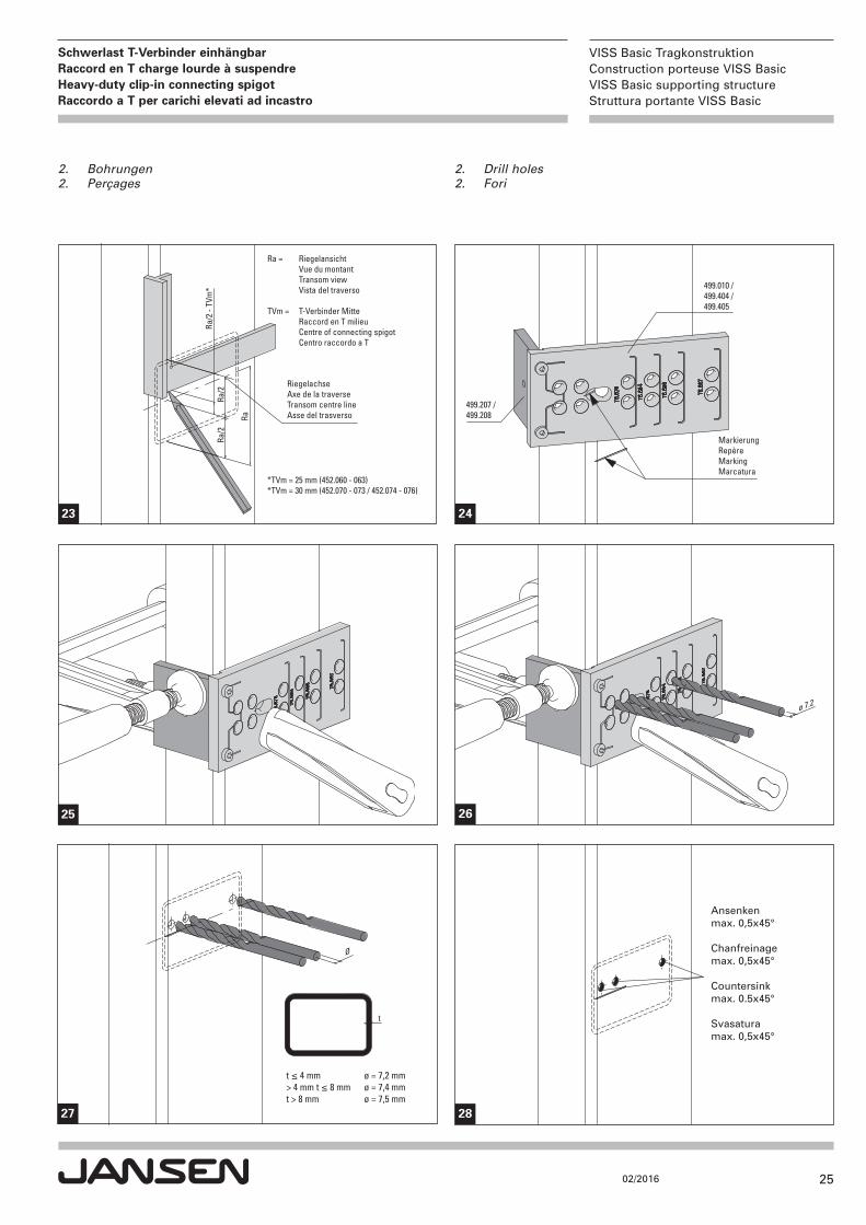
2. Drill holes2. Fori
2. Bohrungen2. Perçages
Ra
Ra/2
- TV
m*
Ra/2
Ra/2
*TVm = 25 mm (452.060 - 063)*TVm = 30 mm (452.070 - 073 / 452.074 - 076)
Ra = Riegelansicht Vue du montant Transom view Vista del traverso
TVm = T-Verbinder Mitte Raccord en T milieu Centre of connecting spigot Centro raccordo a T
RiegelachseAxe de la traverseTransom centre lineAsse del trasverso
499.010 / 499.404 / 499.405
499.207 / 499.208
MarkierungRepèreMarkingMarcatura
23 24
25
ø 7.2
Ø
t
t ≤ 4 mm ø = 7,2 mm> 4 mm t ≤ 8 mm ø = 7,4 mmt > 8 mm ø = 7,5 mm
Ansenken max. 0,5x45°
Chanfreinage max. 0,5x45°
Countersink max. 0.5x45°
Svasatura max. 0,5x45°
26
27 28
26
VISS Basic TragkonstruktionConstruction porteuse VISS BasicVISS Basic supporting structureStruttura portante VISS Basic
02/2016
Schwerlast T-Verbinder einhängbarRaccord en T charge lourde à suspendreHeavy-duty clip-in connecting spigot Raccordo a T per carichi elevati ad incastro
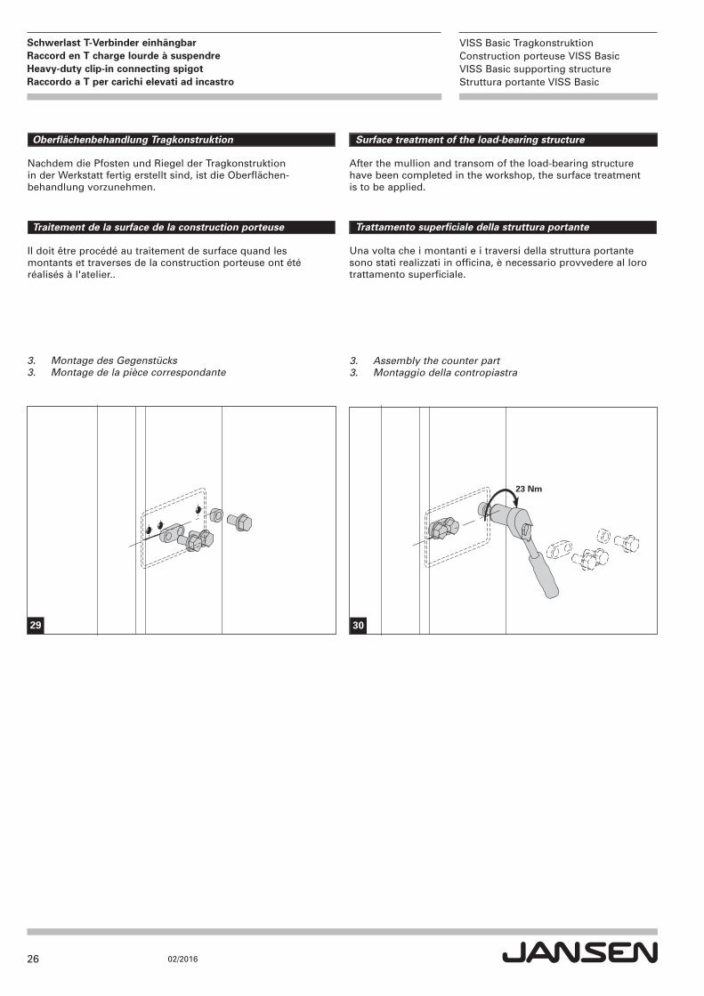
3. Assembly the counter part3. Montaggio della contropiastra
3. Montage des Gegenstücks3. Montage de la pièce correspondante
23 Nm
Oberflächenbehandlung Tragkonstruktion
Nachdem die Pfosten und Riegel der Tragkonstruktion in der Werkstatt fertig erstellt sind, ist die Oberflächen-behandlung vorzunehmen.
Surface treatment of the load-bearing structure
After the mullion and transom of the load-bearing structure have been completed in the workshop, the surface treatment is to be applied.
Traitement de la surface de la construction porteuse
Il doit être procédé au traitement de surface quand les montants et traverses de la construction porteuse ont été réalisés à l'atelier..
Trattamento superficiale della struttura portante
Una volta che i montanti e i traversi della struttura portante sono stati realizzati in officina, è necessario provvedere al loro trattamento superficiale.
29 30
27
VISS Basic TragkonstruktionConstruction porteuse VISS BasicVISS Basic supporting structureStruttura portante VISS Basic
02/2016
Schwerlast T-Verbinder einhängbarRaccord en T charge lourde à suspendreHeavy-duty clip-in connecting spigot Raccordo a T per carichi elevati ad incastro
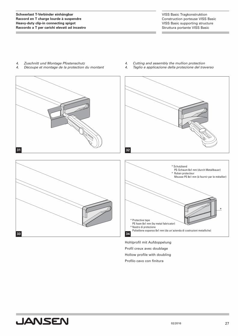
4. Cutting and assembly the mullion protection4. Taglio e applicazione della protezione del traverso
4. Zuschnitt und Montage Pfostenschutz4. Découpe et montage de la protection du montant
31
33
*
* Schutzband PE-Schaum 8x1 mm (durch Metallbauer)* Ruban protecteur Mousse PE 8x1 mm (à fournir par le métallier)
* Protective tape PE foam 8x1 mm (by metal fabricator)* Nastro di protezione Polietilene espanso 8x1 mm (da un'azienda di costruzioni metalliche)
34
32
Hohlprofil mit Aufdoppelung
Profil creux avec doublage
Hollow profile with doubling
Profilo cavo con finitura
28
VISS Basic TragkonstruktionConstruction porteuse VISS BasicVISS Basic supporting structureStruttura portante VISS Basic
02/2016
Schwerlast T-Verbinder einhängbarRaccord en T charge lourde à suspendreHeavy-duty clip-in connecting spigot Raccordo a T per carichi elevati ad incastro
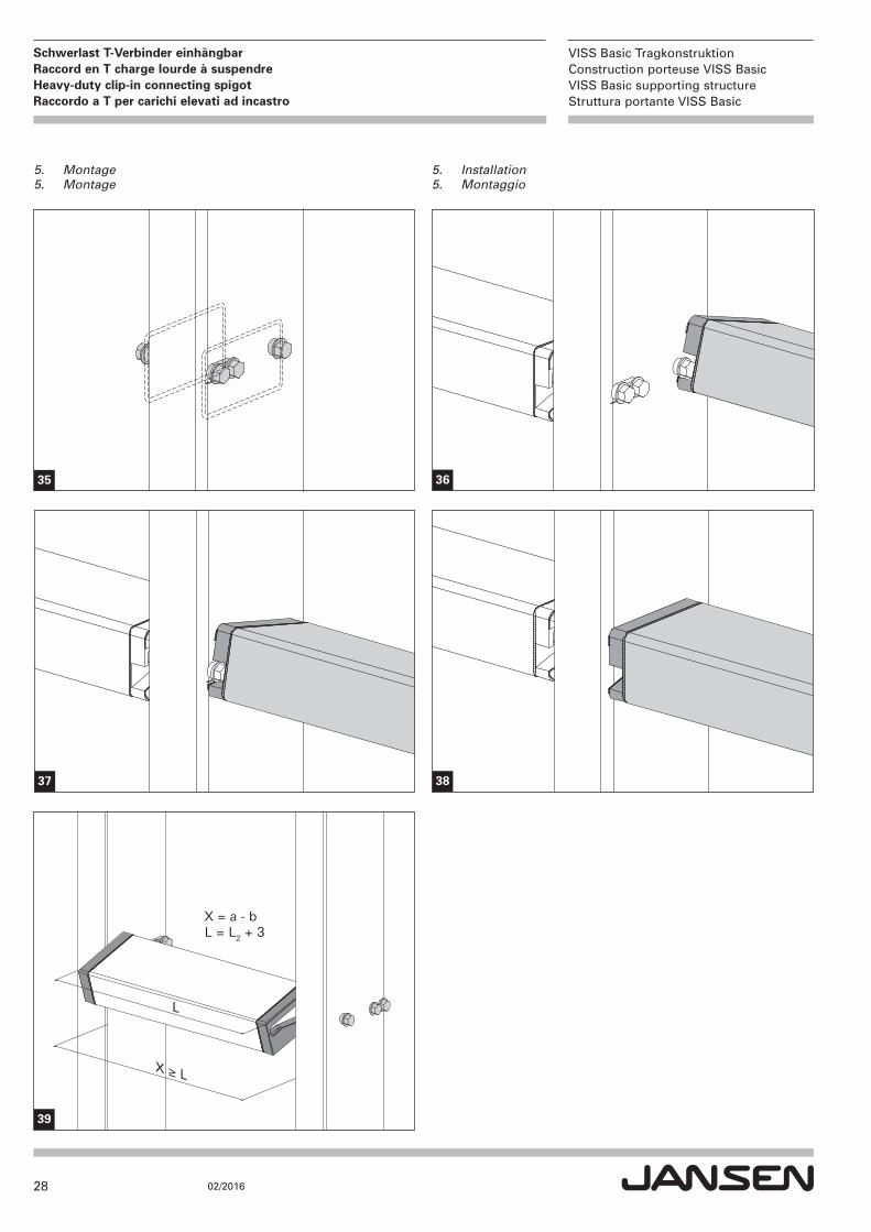
5. Installation5. Montaggio
5. Montage 5. Montage
35 36
37
L
X ≥ L
X = a - bL = L2 + 3
39
38

29
VISS Basic TragkonstruktionConstruction porteuse VISS BasicVISS Basic supporting structureStruttura portante VISS Basic
02/2016
Schwerlast T-Verbinder einhängbarRaccord en T charge lourde à suspendreHeavy-duty clip-in connecting spigot Raccordo a T per carichi elevati ad incastro
452.060
452.061
452.062
452.063
ø 7.2
ø 7.2
ø 7.2
ø 7.2
11.5
29.5
68.5
11.5
29.5
83.5
11.5
29.5
108.5
11.5
29.5
128.5
Ra
Ra/
2 -
16.5
Ra/
2R
a/2
Ra
Ra/
2 -
16.5
Ra/
2R
a/2
Ra
Ra/
2 -
16.5
Ra/
2R
a/2
Ra
Ra/
2 -
16.5
Ra/
2R
a/2
Drilling pattern for CNC programmingBohrbild für CNC-Programmierung
Piano di foratura per la programmazione CNCSchéma de perçage pour programmation CNC
30
VISS Basic TragkonstruktionConstruction porteuse VISS BasicVISS Basic supporting structureStruttura portante VISS Basic
02/2016
Schwerlast T-Verbinder einhängbarRaccord en T charge lourde à suspendreHeavy-duty clip-in connecting spigot Raccordo a T per carichi elevati ad incastro
452.070
452.071
452.072
452.073
ø 7.2
ø 7.2
ø 7.2
ø 7.2
11.5
29.5
68.5
11.5
29.5
88.5
11.5
29.5
108.5
11.5
29.5
138.5
Ra
Ra/
2 -
21.5
Ra/
2R
a/2
Ra
Ra/
2 -
21.5
Ra/
2R
a/2
Ra
Ra/
2 -
21.5
Ra/
2R
a/2
Ra
Ra/
2 -
21.5
Ra/
2R
a/2
31
VISS Basic TragkonstruktionConstruction porteuse VISS BasicVISS Basic supporting structureStruttura portante VISS Basic
02/2016
Schwerlast T-Verbinder einhängbarRaccord en T charge lourde à suspendreHeavy-duty clip-in connecting spigot Raccordo a T per carichi elevati ad incastro
452.074
452.075
452.076
ø 7.2
ø 7.2
ø 7.2
11.5
29.5
168.5
11.5
29.5
208.5
11.5
29.5
268.5
Ra
Ra/
2 -
21.5
Ra/
2R
a/2
Ra
Ra/
2 -
21.5
Ra/
2R
a/2
Ra
Ra/
2 -
21.5
Ra/
2R
a/2
32
VISS Basic TragkonstruktionConstruction porteuse VISS BasicVISS Basic supporting structureStruttura portante VISS Basic
02/2016
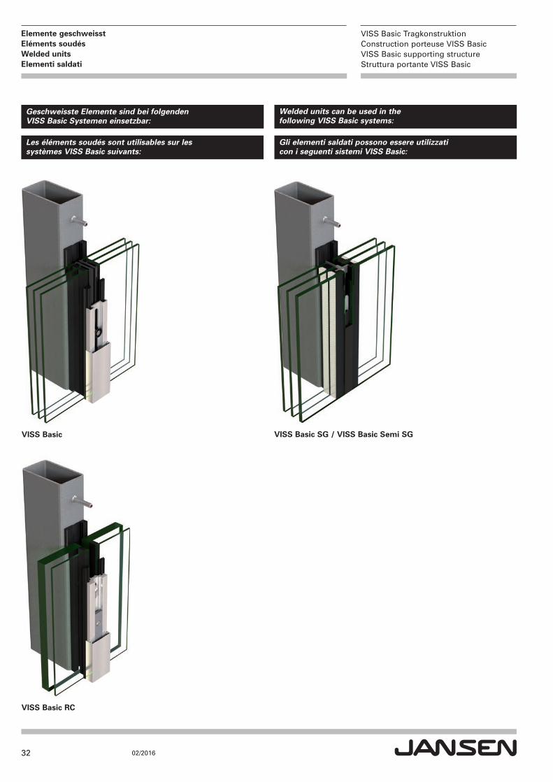
Elemente geschweisstEléments soudésWelded units Elementi saldati
Geschweisste Elemente sind bei folgenden VISS Basic Systemen einsetzbar:
Welded units can be used in the following VISS Basic systems:
Les éléments soudés sont utilisables sur les systèmes VISS Basic suivants:
Gli elementi saldati possono essere utilizzati con i seguenti sistemi VISS Basic:
VISS Basic SG / VISS Basic Semi SGVISS Basic
VISS Basic RC
33
VISS Basic TragkonstruktionConstruction porteuse VISS BasicVISS Basic supporting structureStruttura portante VISS Basic
02/2016
Elemente geschweisstEléments soudésWelded units Elementi saldati
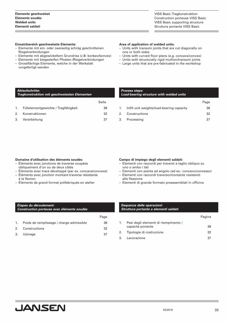
Ablaufschritte: Tragkonstruktion mit geschweissten Elementen
Seite
1. Füllelementgewichte / Tragfähigkeit 36
2. Konstruktionen 32
3. Verarbeitung 37
Étapes du déroulement: Construction porteuse avec éléments soudés
Page
1. Poids de remplissage / charge admissible 36
2. Constructions 32
3. Usinage 37
Process steps: Load-bearing structure with welded units
Page
1. Infill unit weights/load-bearing capacity 36
2. Constructions 32
3. Processing 37
Sequenza delle operazioni: Struttura portante a elementi saldati
Pagina
1. Pesi degli elementi di riempimento / capacità portante 36
2. Tipologie di costruzione 32
3. Lavorazione 37
Einsatzbereich geschweisste Elemente:– Elemente mit ein- oder zweiseitig schräg geschnittenen Riegelverbindungen
– Elemente mit abgewickeltem Grundriss (z.B: konkav/konvex)– Elemente mit biegesteifen Pfosten-/Riegelverbindungen– Grossflächige Elemente, welche in der Werkstatt vorgefertigt werden
Domaine d'utilisation des éléments soudés:– Éléments avec jonctions de traverse coupées obliquement d'un ou de deux côtés
– Éléments avec tracé développé (par ex. concave/convexe)– Éléments avec jonction montant-traverse résistante à la flexion
– Éléments de grand format préfabriqués en atelier
Area of application of welded units:– Units with transom joints that are cut diagonally on one or both sides
– Units with curved floor plans (e.g. concave/convex)– Units with structurally rigid mullion/transom joints– Large units that are pre-fabricated in the workshop
Campo di impiego degli elementi saldati:– Elementi con raccordi per traversi a taglio obliquo su uno o ambo i lati
– Elementi con pianta ad angolo (ad es.: concavo/convesso)– Elementi con raccordi traverso/montante resistenti alla flessione
– Elementi di grande formato preassemblati in officina
34
VISS Basic TragkonstruktionConstruction porteuse VISS BasicVISS Basic supporting structureStruttura portante VISS Basic
02/2016
Elemente geschweisstEléments soudésWelded units Elementi saldati
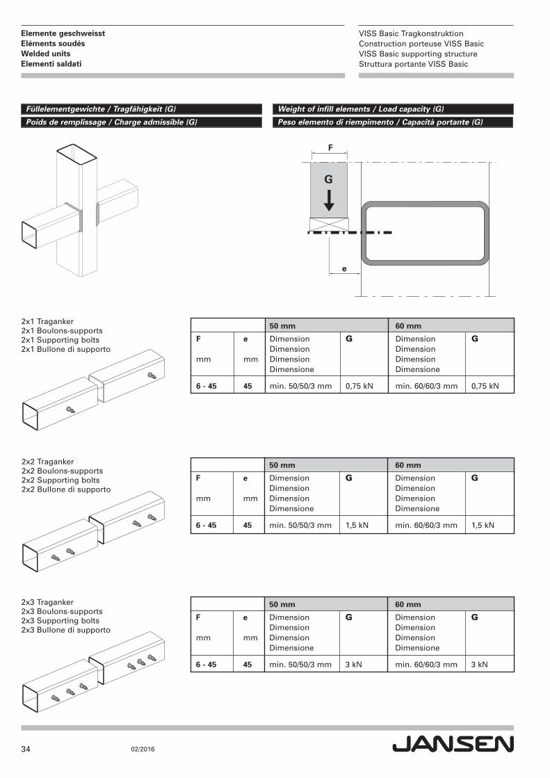
2x1 Traganker2x1 Boulons-supports2x1 Supporting bolts2x1 Bullone di supporto
2x2 Traganker2x2 Boulons-supports2x2 Supporting bolts2x2 Bullone di supporto
2x3 Traganker2x3 Boulons-supports2x3 Supporting bolts2x3 Bullone di supporto
Weight of infill elements / Load capacity (G)Füllelementgewichte / Tragfähigkeit (G)
Peso elemento di riempimento / Capacità portante (G)Poids de remplissage / Charge admissible (G)
G
e
F
50 mm 60 mm
F e Dimension G Dimension G Dimension Dimension
mm mm Dimension Dimension Dimensione Dimensione
6 - 45 45 min. 50/50/3 mm 0,75 kN min. 60/60/3 mm 0,75 kN
50 mm 60 mm
F e Dimension G Dimension G Dimension Dimension
mm mm Dimension Dimension Dimensione Dimensione
6 - 45 45 min. 50/50/3 mm 1,5 kN min. 60/60/3 mm 1,5 kN
50 mm 60 mm
F e Dimension G Dimension G Dimension Dimension
mm mm Dimension Dimension Dimensione Dimensione
6 - 45 45 min. 50/50/3 mm 3 kN min. 60/60/3 mm 3 kN
35
VISS Basic TragkonstruktionConstruction porteuse VISS BasicVISS Basic supporting structureStruttura portante VISS Basic
02/2016
Elemente geschweisstEléments soudésWelded units Elementi saldati
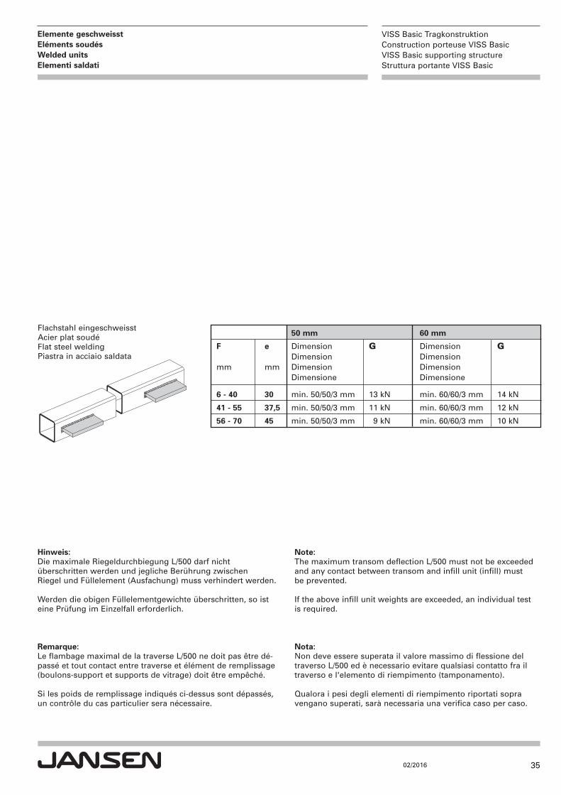
Flachstahl eingeschweisstAcier plat soudéFlat steel weldingPiastra in acciaio saldata
50 mm 60 mm
F e Dimension G Dimension G Dimension Dimension
mm mm Dimension Dimension Dimensione Dimensione
6 - 40 30 min. 50/50/3 mm 13 kN min. 60/60/3 mm 14 kN
41 - 55 37,5 min. 50/50/3 mm 11 kN min. 60/60/3 mm 12 kN
56 - 70 45 min. 50/50/3 mm 9 kN min. 60/60/3 mm 10 kN
Hinweis:Die maximale Riegeldurchbiegung L/500 darf nicht überschritten werden und jegliche Berührung zwischen Riegel und Füllelement (Ausfachung) muss verhindert werden.
Werden die obigen Füllelementgewichte überschritten, so isteine Prüfung im Einzelfall erforderlich.
Remarque:Le flambage maximal de la traverse L/500 ne doit pas être dé-passé et tout contact entre traverse et élément de remplissage(boulons-support et supports de vitrage) doit être empêché.
Si les poids de remplissage indiqués ci-dessus sont dépassés,un contrôle du cas particulier sera nécessaire.
Note:The maximum transom deflection L/500 must not be exceededand any contact between transom and infill unit (infill) mustbe prevented.
If the above infill unit weights are exceeded, an individual testis required.
Nota:Non deve essere superata il valore massimo di flessione deltraverso L/500 ed è necessario evitare qualsiasi contatto fra iltraverso e l'elemento di riempimento (tamponamento).
Qualora i pesi degli elementi di riempimento riportati sopravengano superati, sarà necessaria una verifica caso per caso.
36
VISS Basic TragkonstruktionConstruction porteuse VISS BasicVISS Basic supporting structureStruttura portante VISS Basic
02/2016
Elemente geschweisstEléments soudésWelded units Elementi saldati
ConstructionsKonstruktionen
Tipologie di costruzioneConstructions
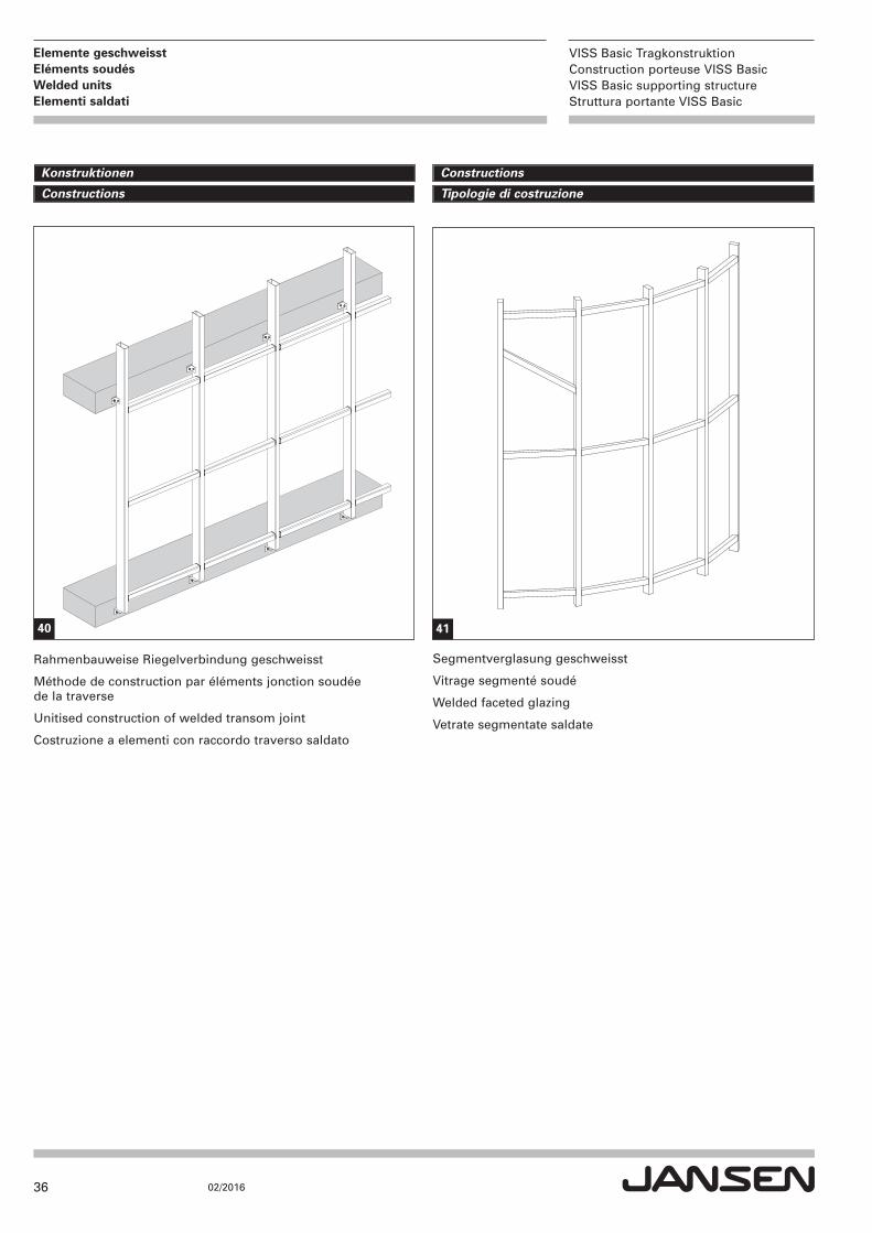
Rahmenbauweise Riegelverbindung geschweisst
Méthode de construction par éléments jonction soudée de la traverse
Unitised construction of welded transom joint
Costruzione a elementi con raccordo traverso saldato
Segmentverglasung geschweisst
Vitrage segmenté soudé
Welded faceted glazing
Vetrate segmentate saldate
40 41
37
VISS Basic TragkonstruktionConstruction porteuse VISS BasicVISS Basic supporting structureStruttura portante VISS Basic
02/2016
Elemente geschweisstEléments soudésWelded units Elementi saldati
ProcessingVerarbeitung
LavorazioneUsinage
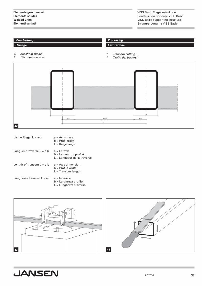
b b
b/2b/2
a
L = a-b
Länge Riegel L = a-b a = Achsmass b = Profilbreite L = Riegellänge
Longueur traverse L = a-b a = Entraxe b = Largeur du profilé L = Longueur de la traverse
Length of transom L = a-b a = Axis dimension b = Profile width L = Transom length
Lunghezza traverso L = a-b a = Interasse b = Larghezza profilo L = Lunghezza traverso
42
43 44
1. Transom cutting1. Taglio dei traversi
1. Zuschnitt Riegel 1. Découpe traverse
38
VISS Basic TragkonstruktionConstruction porteuse VISS BasicVISS Basic supporting structureStruttura portante VISS Basic
02/2016
Elemente geschweisstEléments soudésWelded units Elementi saldati
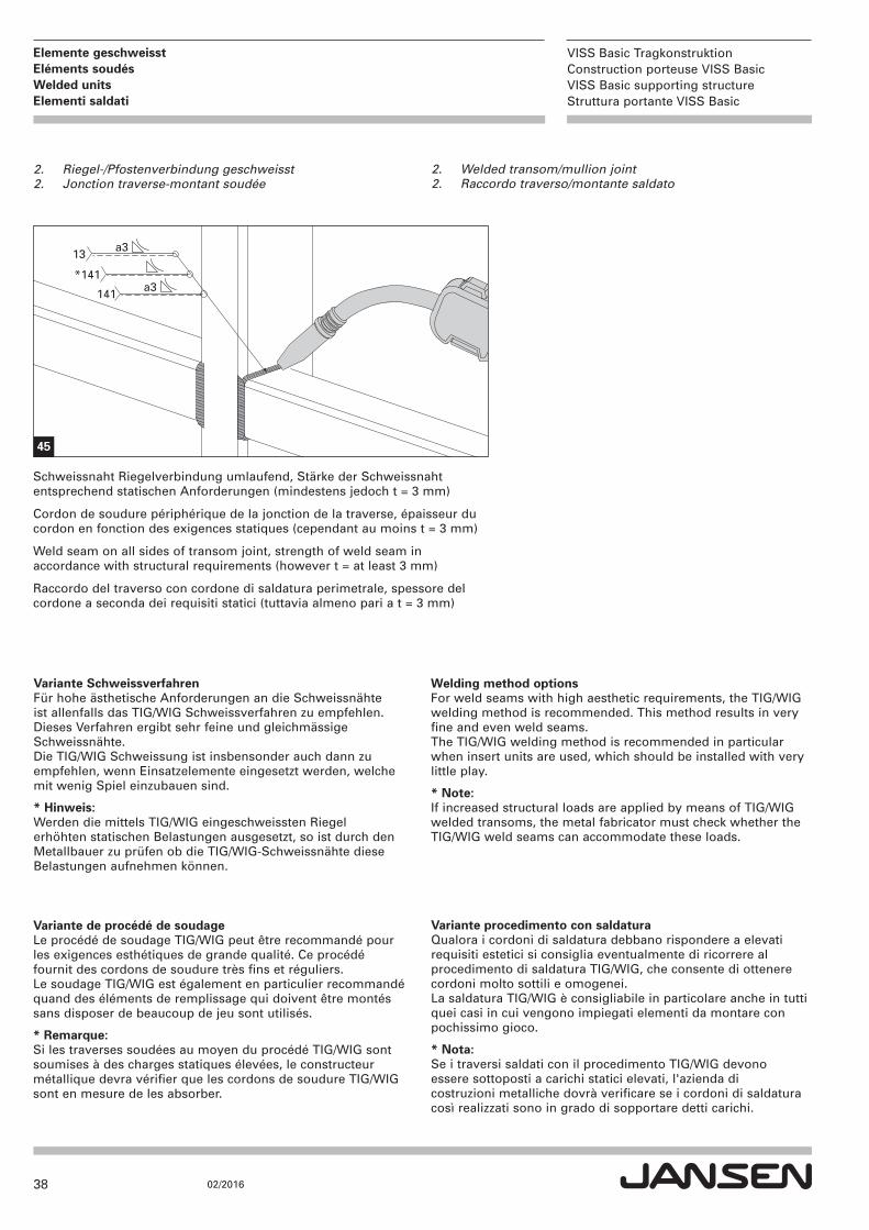
2. Welded transom/mullion joint2. Raccordo traverso/montante saldato
2. Riegel-/Pfostenverbindung geschweisst 2. Jonction traverse-montant soudée
a313
*141a3141
45
Variante SchweissverfahrenFür hohe ästhetische Anforderungen an die Schweissnähte ist allenfalls das TIG/WIG Schweissverfahren zu empfehlen.Dieses Verfahren ergibt sehr feine und gleichmässigeSchweissnähte.Die TIG/WIG Schweissung ist insbensonder auch dann zu empfehlen, wenn Einsatzelemente eingesetzt werden, welchemit wenig Spiel einzubauen sind.
* Hinweis:Werden die mittels TIG/WIG eingeschweissten Riegel erhöhten statischen Belastungen ausgesetzt, so ist durch den Metallbauer zu prüfen ob die TIG/WIG-Schweissnähte diese Belastungen aufnehmen können.
Variante de procédé de soudageLe procédé de soudage TIG/WIG peut être recommandé pourles exigences esthétiques de grande qualité. Ce procédé fournit des cordons de soudure très fins et réguliers.Le soudage TIG/WIG est également en particulier recommandéquand des éléments de remplissage qui doivent être montéssans disposer de beaucoup de jeu sont utilisés.
* Remarque:Si les traverses soudées au moyen du procédé TIG/WIG sont soumises à des charges statiques élevées, le constructeur métallique devra vérifier que les cordons de soudure TIG/WIG sont en mesure de les absorber.
Welding method optionsFor weld seams with high aesthetic requirements, the TIG/WIGwelding method is recommended. This method results in veryfine and even weld seams.The TIG/WIG welding method is recommended in particularwhen insert units are used, which should be installed with verylittle play.
* Note:If increased structural loads are applied by means of TIG/WIG welded transoms, the metal fabricator must check whether the TIG/WIG weld seams can accommodate these loads.
Variante procedimento con saldaturaQualora i cordoni di saldatura debbano rispondere a elevatirequisiti estetici si consiglia eventualmente di ricorrere al procedimento di saldatura TIG/WIG, che consente di ottenerecordoni molto sottili e omogenei.La saldatura TIG/WIG è consigliabile in particolare anche in tuttiquei casi in cui vengono impiegati elementi da montare conpochissimo gioco.
* Nota:Se i traversi saldati con il procedimento TIG/WIG devono essere sottoposti a carichi statici elevati, l'azienda di costruzioni metalliche dovrà verificare se i cordoni di saldatura così realizzati sono in grado di sopportare detti carichi.
Schweissnaht Riegelverbindung umlaufend, Stärke der Schweissnaht entsprechend statischen Anforderungen (mindestens jedoch t = 3 mm)
Cordon de soudure périphérique de la jonction de la traverse, épaisseur ducordon en fonction des exigences statiques (cependant au moins t = 3 mm)
Weld seam on all sides of transom joint, strength of weld seam in accordance with structural requirements (however t = at least 3 mm)
Raccordo del traverso con cordone di saldatura perimetrale, spessore delcordone a seconda dei requisiti statici (tuttavia almeno pari a t = 3 mm)
39
VISS Basic TragkonstruktionConstruction porteuse VISS BasicVISS Basic supporting structureStruttura portante VISS Basic
02/2016
Elemente geschweisstEléments soudésWelded units Elementi saldati
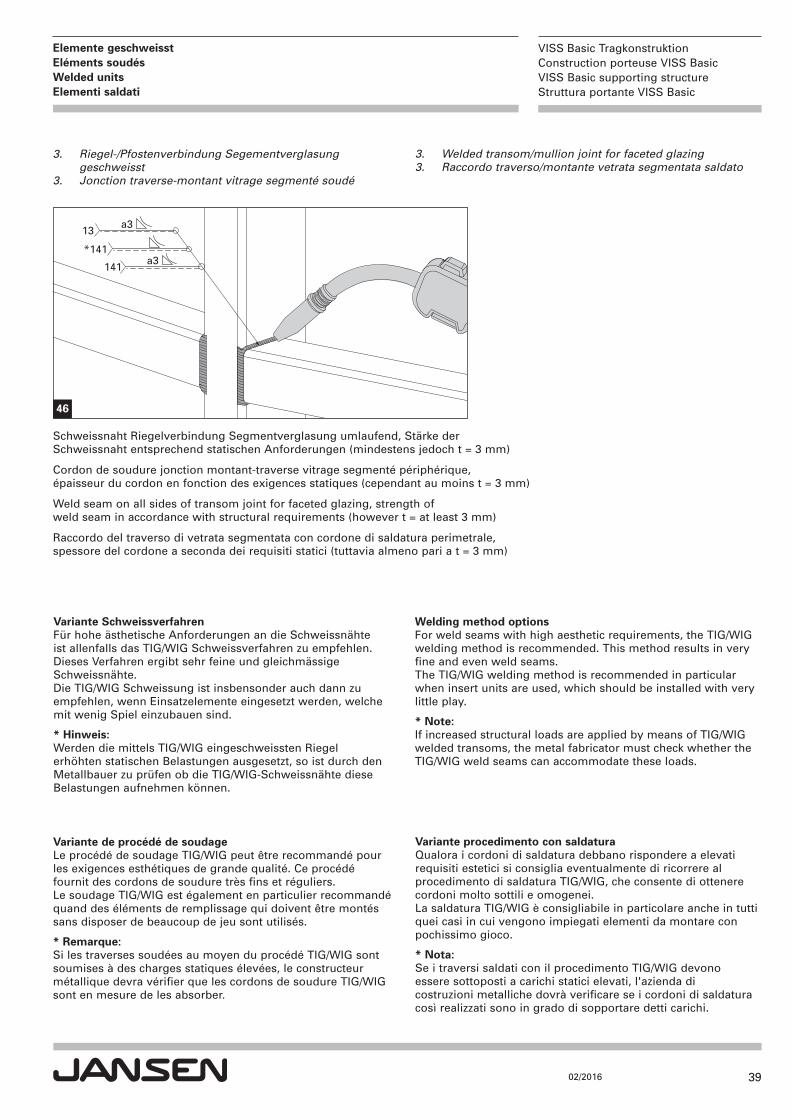
3. Welded transom/mullion joint for faceted glazing3. Raccordo traverso/montante vetrata segmentata saldato
3. Riegel-/Pfostenverbindung Segementverglasunggeschweisst
3. Jonction traverse-montant vitrage segmenté soudé
a313
*141a3141
46
Variante SchweissverfahrenFür hohe ästhetische Anforderungen an die Schweissnähte ist allenfalls das TIG/WIG Schweissverfahren zu empfehlen.Dieses Verfahren ergibt sehr feine und gleichmässigeSchweissnähte.Die TIG/WIG Schweissung ist insbensonder auch dann zu empfehlen, wenn Einsatzelemente eingesetzt werden, welchemit wenig Spiel einzubauen sind.
* Hinweis:Werden die mittels TIG/WIG eingeschweissten Riegel erhöhten statischen Belastungen ausgesetzt, so ist durch den Metallbauer zu prüfen ob die TIG/WIG-Schweissnähte diese Belastungen aufnehmen können.
Variante de procédé de soudageLe procédé de soudage TIG/WIG peut être recommandé pourles exigences esthétiques de grande qualité. Ce procédé fournit des cordons de soudure très fins et réguliers.Le soudage TIG/WIG est également en particulier recommandéquand des éléments de remplissage qui doivent être montéssans disposer de beaucoup de jeu sont utilisés.
* Remarque:Si les traverses soudées au moyen du procédé TIG/WIG sont soumises à des charges statiques élevées, le constructeur métallique devra vérifier que les cordons de soudure TIG/WIG sont en mesure de les absorber.
Welding method optionsFor weld seams with high aesthetic requirements, the TIG/WIGwelding method is recommended. This method results in veryfine and even weld seams.The TIG/WIG welding method is recommended in particularwhen insert units are used, which should be installed with verylittle play.
* Note:If increased structural loads are applied by means of TIG/WIG welded transoms, the metal fabricator must check whether the TIG/WIG weld seams can accommodate these loads.
Variante procedimento con saldaturaQualora i cordoni di saldatura debbano rispondere a elevatirequisiti estetici si consiglia eventualmente di ricorrere al procedimento di saldatura TIG/WIG, che consente di ottenerecordoni molto sottili e omogenei.La saldatura TIG/WIG è consigliabile in particolare anche in tuttiquei casi in cui vengono impiegati elementi da montare conpochissimo gioco.
* Nota:Se i traversi saldati con il procedimento TIG/WIG devono essere sottoposti a carichi statici elevati, l'azienda di costruzioni metalliche dovrà verificare se i cordoni di saldatura così realizzati sono in grado di sopportare detti carichi.
Schweissnaht Riegelverbindung Segmentverglasung umlaufend, Stärke der Schweissnaht entsprechend statischen Anforderungen (mindestens jedoch t = 3 mm)
Cordon de soudure jonction montant-traverse vitrage segmenté périphérique, épaisseur du cordon en fonction des exigences statiques (cependant au moins t = 3 mm)
Weld seam on all sides of transom joint for faceted glazing, strength of weld seam in accordance with structural requirements (however t = at least 3 mm)
Raccordo del traverso di vetrata segmentata con cordone di saldatura perimetrale, spessore del cordone a seconda dei requisiti statici (tuttavia almeno pari a t = 3 mm)
40
VISS Basic TragkonstruktionConstruction porteuse VISS BasicVISS Basic supporting structureStruttura portante VISS Basic
02/2016
Elemente geschweisstEléments soudésWelded units Elementi saldati
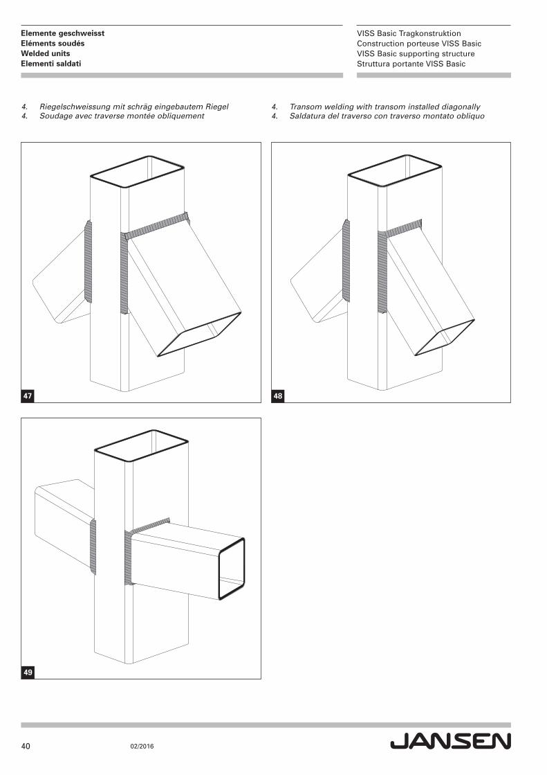
4. Transom welding with transom installed diagonally4. Saldatura del traverso con traverso montato obliquo
4. Riegelschweissung mit schräg eingebautem Riegel4. Soudage avec traverse montée obliquement
47
49
48
41
VISS Basic TragkonstruktionConstruction porteuse VISS BasicVISS Basic supporting structureStruttura portante VISS Basic
02/2016
Elemente geschweisstEléments soudésWelded units Elementi saldati
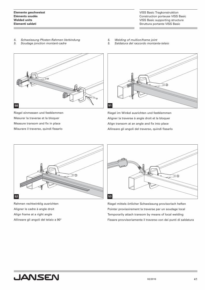
5. Welding of mullion/frame joint5. Saldatura del raccordo montante-telaio
5. Schweissung Pfosten-Rahmen-Verbindung5. Soudage jonction montant-cadre
Riegel einmessen und festklemmen
Mesurer la traverse et la bloquer
Measure transom and fix in place
Misurare il traverso, quindi fissarlo
Riegel im Winkel ausrichten und festklemmen
Aligner la traverse à angle droit et la bloquer
Align transom at an angle and fix into place
Allineare gli angoli del traverso, quindi fissarlo
Rahmen rechtwinklig ausrichten
Aligner le cadre à angle droit
Align frame at a right angle
Allineare gli angoli del telaio a 90°
Riegel mittels örtlicher Schweissung provisorisch heften
Pointer provisoirement la traverse par un soudage local
Temporarily attach transom by means of local welding
Fissare provvisoriamente il traverso con dei punti di saldatura
50 51
52 53
42
VISS Basic TragkonstruktionConstruction porteuse VISS BasicVISS Basic supporting structureStruttura portante VISS Basic
02/2016
Elemente geschweisstEléments soudésWelded units Elementi saldati
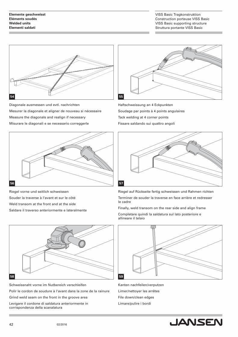
Haftschweissung an 4 Eckpunkten
Soudage par points à 4 points angulaires
Tack welding at 4 corner points
Fissare saldando sui quattro angoli
Diagonale ausmessen und evtl. nachrichten
Mesurer la diagonale et aligner de nouveau si nécessaire
Measure the diagonals and realign if necessary
Misurare le diagonali e se necessario correggerle
Riegel vorne und seitlich schweissen
Souder la traverse à l'avant et sur le côté
Weld transom at the front and at the side
Saldare il traverso anteriormente e lateralmente
Schweissnaht vorne im Nutbereich verschleifen
Polir le cordon de soudure à l'avant dans la zone de la rainure
Grind weld seam on the front in the groove area
Levigare il cordone di saldatura anteriormente in corrispondenza della scanalatura
Kanten nachfeilen/verputzen
Limer/nettoyer les arrêtes
File down/clean edges
Limare/pulire i bordi
Riegel auf Rückseite fertig schweissen und Rahmen richten
Terminer de souder la traverse en face arrière et redresser le cadre
Finally, weld transom on the rear side and align frame
Completare quindi la saldatura sul lato posteriore e allineare il telaio
54 55
56
58 59
57
43
VISS Basic TragkonstruktionConstruction porteuse VISS BasicVISS Basic supporting structureStruttura portante VISS Basic
02/2016
Bauanschlüsse Raccords au murAttachment to structure Raccordi alla muratura
Ausführungsbeispiele
Seite
1. Ausführungsbeispiele Fussplatten 44
2. Ausführungsbeispiele Kopfplatten/stirnseitige Befestigungen 45
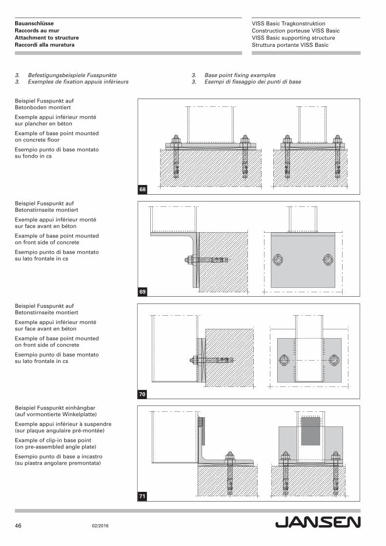
3. Befestigungsbeispiele Fusspunkte 46
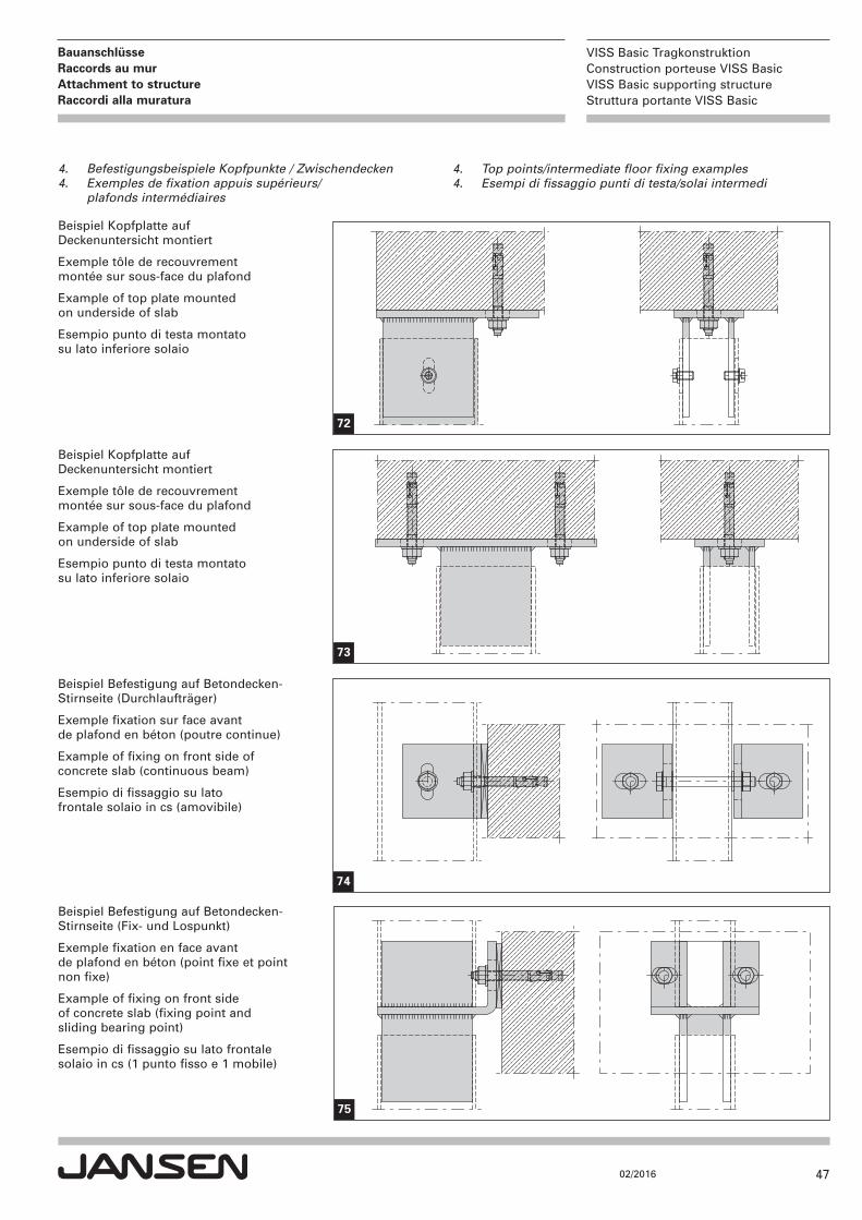
4. Befestigungsbeispiele Kopfpunkte/Zwischendecken 47
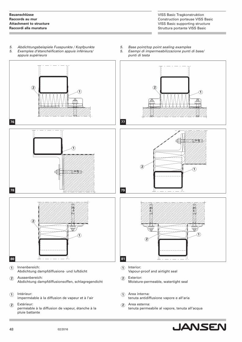
5. Abdichtungsbeispiele Fusspunkte/Kopfpunkte 48
6. Abdichtung Tragkonstruktion 49
Exemples d'exécution
Page
1. Exemples d'exécution semelles 44
2. Exemples d'exécution tôles de recouvrement/fixations en face avant 45
3. Exemples de fixation des appuis inférieurs 46
4. Exemples de fixation appuis supérieurs/plafonds intermédiaires 47
5. Exemples d'étanchéification appuis inférieurs/appuis supérieurs 48
6. Étanchéification de la construction porteuse 49
Design examples
Page
1. Base plate design examples 44
2. Top plate/front end fixing design examples 45
3. Base point fixing examples 46
4. Top point/intermediate floor fixing examples 47
5. Base point/top point sealing examples 48
6. Sealing of load-bearing structure 49
Esempi di realizzazione
Pagina
1. Esempi di realizzazione delle piastre di base 44
2. Esempi di realizzazione delle piastre di testa/fissaggi frontali 45
3. Esempi di fissaggio dei punti di base 46
4. Esempi di fissaggio punti di testa/solai intermedi 47
5. Esempi di impermeabilizzazione punti di base/punti di testa 48
6. Impermeabilizzazione struttura portante 49
44
VISS Basic TragkonstruktionConstruction porteuse VISS BasicVISS Basic supporting structureStruttura portante VISS Basic
02/2016
Bauanschlüsse Raccords au murAttachment to structure Raccordi alla muratura
1. Base plate design examples1. Esempi di realizzazione delle piastre di base
1. Ausführungsbeispiele Fussplatten1. Exemples d'exécution semelles
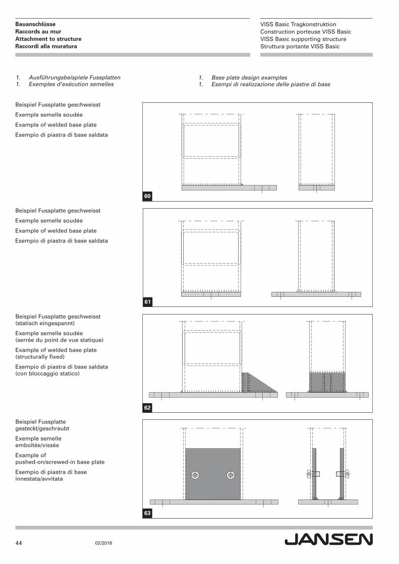
Beispiel Fussplatte geschweisst
Exemple semelle soudée
Example of welded base plate
Esempio di piastra di base saldata
Beispiel Fussplatte geschweisst
Exemple semelle soudée
Example of welded base plate
Esempio di piastra di base saldata
Beispiel Fussplatte geschweisst (statisch eingespannt)
Exemple semelle soudée (serrée du point de vue statique)
Example of welded base plate (structurally fixed)
Esempio di piastra di base saldata (con bloccaggio statico)
Beispiel Fussplatte gesteckt/geschraubt
Exemple semelle emboîtée/vissée
Example of pushed-on/screwed-in base plate
Esempio di piastra di base innestata/avvitata
60
61
62
63
45
VISS Basic TragkonstruktionConstruction porteuse VISS BasicVISS Basic supporting structureStruttura portante VISS Basic
02/2016
Bauanschlüsse Raccords au murAttachment to structure Raccordi alla muratura
2. Top plate examples2. Esempi di realizzazione delle piastre di testa
2. Ausführungsbeispiele Kopfplatten 2. Exemples tôles de recouvrement
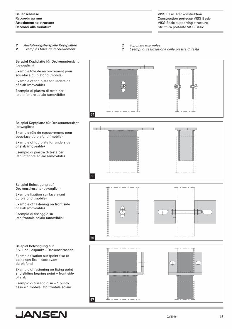
Beispiel Kopfplatte für Deckenuntersicht(beweglich)
Exemple tôle de recouvrement pour sous-face du plafond (mobile)
Example of top plate for underside of slab (moveable)
Esempio di piastra di testa per lato inferiore solaio (amovibile)
Beispiel Kopfplatte für Deckenuntersicht(beweglich)
Exemple tôle de recouvrement pour sous-face du plafond (mobile)
Example of top plate for underside of slab (moveable)
Esempio di piastra di testa per lato inferiore solaio (amovibile)
Beispiel Befestigung auf Deckenstirnseite (beweglich)
Exemple fixation sur face avant du plafond (mobile)
Example of fastening on front side of slab (moveable)
Esempio di fissaggio su lato frontale solaio (amovibile)
Beispiel Befestigung auf Fix- und Lospunkt – Deckenstirnseite
Exemple fixation sur (point fixe et point non fixe – face avant du plafond
Example of fastening on fixing point and sliding bearing point – front side of slab
Esempio di fissaggio su – 1 punto fisso e 1 mobile lato frontale solaio
64
65
66
67
46
VISS Basic TragkonstruktionConstruction porteuse VISS BasicVISS Basic supporting structureStruttura portante VISS Basic
02/2016
Bauanschlüsse Raccords au murAttachment to structure Raccordi alla muratura
3. Base point fixing examples3. Esempi di fissaggio dei punti di base
3. Befestigungsbeispiele Fusspunkte3. Exemples de fixation appuis inférieurs
Beispiel Fusspunkt auf Betonboden montiert
Exemple appui inférieur monté sur plancher en béton
Example of base point mounted on concrete floor
Esempio punto di base montato su fondo in cs
Beispiel Fusspunkt auf Betonstirnseite montiert
Exemple appui inférieur monté sur face avant en béton
Example of base point mounted on front side of concrete
Esempio punto di base montato su lato frontale in cs
Beispiel Fusspunkt auf Betonstirnseite montiert
Exemple appui inférieur monté sur face avant en béton
Example of base point mounted on front side of concrete
Esempio punto di base montato su lato frontale in cs
Beispiel Fusspunkt einhängbar(auf vormontierte Winkelplatte)
Exemple appui inférieur à suspendre (sur plaque angulaire pré-montée)
Example of clip-in base point (on pre-assembled angle plate)
Esempio punto di base a incastro (su piastra angolare premontata)
68
69
70
71
47
VISS Basic TragkonstruktionConstruction porteuse VISS BasicVISS Basic supporting structureStruttura portante VISS Basic
02/2016
Bauanschlüsse Raccords au murAttachment to structure Raccordi alla muratura
4. Top points/intermediate floor fixing examples4. Esempi di fissaggio punti di testa/solai intermedi
4. Befestigungsbeispiele Kopfpunkte / Zwischendecken4. Exemples de fixation appuis supérieurs/ plafonds intermédiaires
Beispiel Kopfplatte auf Deckenuntersicht montiert
Exemple tôle de recouvrement montée sur sous-face du plafond
Example of top plate mounted on underside of slab
Esempio punto di testa montato su lato inferiore solaio
Beispiel Kopfplatte auf Deckenuntersicht montiert
Exemple tôle de recouvrement montée sur sous-face du plafond
Example of top plate mounted on underside of slab
Esempio punto di testa montato su lato inferiore solaio
Beispiel Befestigung auf Betondecken-Stirnseite (Durchlaufträger)
Exemple fixation sur face avant de plafond en béton (poutre continue)
Example of fixing on front side of concrete slab (continuous beam)
Esempio di fissaggio su lato frontale solaio in cs (amovibile)
Beispiel Befestigung auf Betondecken-Stirnseite (Fix- und Lospunkt)
Exemple fixation en face avant de plafond en béton (point fixe et point non fixe)
Example of fixing on front side of concrete slab (fixing point and sliding bearing point)
Esempio di fissaggio su lato frontale solaio in cs (1 punto fisso e 1 mobile)
72
73
74
75
48
VISS Basic TragkonstruktionConstruction porteuse VISS BasicVISS Basic supporting structureStruttura portante VISS Basic
02/2016
Bauanschlüsse Raccords au murAttachment to structure Raccordi alla muratura
5. Base point/top point sealing examples5. Esempi di impermeabilizzazione punti di base/ punti di testa
5. Abdichtungsbeispiele Fusspunkte / Kopfpunkte5. Exemples d'étanchéification appuis inférieurs/ appuis supérieurs
21
21
1
1
76 77
78
Innenbereich: Abdichtung dampfdiffusions- und luftdicht
Aussenbereich: Abdichtung dampfdiffusionsoffen, schlagregendicht
Intérieur: imperméable à la diffusion de vapeur et à l'air
Extérieur: perméable à la diffusion de vapeur, étanche à la pluie battante
1
2
21
21
79
80 81
2
1
2
1 Interior: Vapour-proof and airtight seal
Exterior: Moisture-permeable, watertight seal
Area interna: tenuta antidiffusione vapore e all'aria
Area esterna: tenuta permeabile al vapore, tenuta all'acqua
2
1
2
49
VISS Basic TragkonstruktionConstruction porteuse VISS BasicVISS Basic supporting structureStruttura portante VISS Basic
02/2016
Bauanschlüsse Raccords au murAttachment to structure Raccordi alla muratura
6. Abdichtung Tragkonstruktion
Nach der Montage der VISS Basic-Tragkonstruktion am Bausollte der Einbau der Glaselemente grundsätzlich möglichstrasch erfolgen. Ist dies aus verschiedenen Gründen nicht möglich, so sollte die Tragkonstruktion bei schlechter Witterung mittels Planen abgedeckt werden. Dies gilt besonders bei exponierten, der Witterung ausgesetzten, Fassadenkonstruktionen.Vor der Montage der Innendichtungen resp. vor dem Glas-einbau prüfen, ob sich allenfalls Wasser im Riegelhohlraumbefindet. Falls ja, Wasser/Feuchtigkeit ausblasen resp. trocknen (Abb. 01/02).
6. Étanchéification de la construction porteuse
Les éléments de vitrage devraient toujours être montés rapidement après l'installation de la construction porteuse VISS Basic. Si cela est impossible pour différentes raisons, la construction porteuse devrait être recouverte de bâches en cas de mauvais temps. Cela est en particulier le cas pour les constructions de façade soumises aux intempéries.Contrôler avant de monter les joints intérieurs et le vitrage si de l'eau se trouve dans la cavité de la traverse. Si cela est le cas, éliminer l'eau/l'humidité par soufflage et sécher (Fig. 01/02).
6. Sealing of load-bearing structure
After installation of the VISS Basic load-bearing structure on site, the glass units must always be installed as quickly as possible. If this is not possible for various reasons, the load-bearing structure must be covered by tarpaulin in case of bad weather. This applies in particular to façade constructions that are exposed to the weather.Before installation of the internal gaskets or before installing the glass, check whether there is water in the transom hollow space. If so, blow out or dry the water/moisture (Fig. 01/02).
6. Impermeabilizzazione struttura portante
Dopo il montaggio della struttura portante VISS Basic alla muratura dovrebbe seguire, il più presto possibile, quello degli elementi in vetro. Se questo non dovesse essere possibile, per svariati motivi, si dovrà provvedere, in caso di maltempo, a coprire la struttura portante con dei teli. Quanto detto vale in particolare per facciate esposte ai fenomeni atmosferici.Prima di montare le guarnizioni interne o i vetri, verificare l'eventuale presenza di acqua nelle cavità del traverso. In caso affermativo soffiare via l'acqua/l'umidità o asciugarla (fig. 01/02).
50
VISS Basic TragkonstruktionConstruction porteuse VISS BasicVISS Basic supporting structureStruttura portante VISS Basic
02/2016
Systemtoleranzen Tolérances du systèmeSystem tolerances Tolleranze del sistema
max
. 1 m
m
82
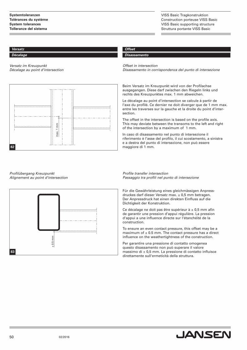
OffsetVersatz
DisassamentoDécalage
Beim Versatz im Kreuzpunkt wird von der Profilachse ausgegangen. Diese darf zwischen den Riegeln links undrechts des Kreuzpunktes max. 1 mm abweichen.
Le décalage au point d'intersection se calcule à partir de l'axe du profilé. Ce dernier ne doit diverger que de 1 mm max.entre les traverses sur la gauche et la droite du point d'inter-section.
The offset in the intersection is based on the profile axis. This may deviate between the transoms to the left and right of the intersection by a maximum of 1 mm.
In caso di disassamento nel punto di intersezione il riferimento è l'asse del profilo, il cui scostamento, a sinistra e a destra del punto di intersezione, non può essere maggiore di 1 mm.
± 0.
5 m
m
83
Profile transfer intersectionPassaggio tra profili nel punto di intersezione
Profilübergang KreuzpunktAlignement au point d'intersection
Offset in intersectionDisassamento in corrispondenza del punto di intersezione
Versatz im KreuzpunktDécalage au point d'intersection
Für die Gewährleistung eines gleichmässigen Anpress-druckes darf dieser Versatz max. ± 0,5 mm betragen. Der Anpressdruck hat einen direkten Einfluss auf dieDichtigkeit der Konstruktion.
Ce décalage ne doit pas être supérieur à ± 0,5 mm afin de garantir une pression d'appui régulière. La pression d'appui a une influence directe sur l'étanchéité de la construction.
To ensure an even contact pressure, this offset may be a maximum of ± 0.5 mm. The contact pressure has a directinfluence on the weathertightness of the construction.
Per garantire una pressione di contatto omogenea questo disassamento non può superare il valore massimo di ± 0,5 mm. La pressione di contatto influisce direttamente sull'ermeticità della struttura.

51
VISS Basic TragkonstruktionConstruction porteuse VISS BasicVISS Basic supporting structureStruttura portante VISS Basic
02/2016
Systemtoleranzen Tolérances du systèmeSystem tolerances Tolleranze del sistema
L
2 m
m/m
84
= =
85
± 1 mm ± 0.5 mm
h ≤
80
h >
80
86
Geradheit der Profile: Die Abweichung bei der Geradheit der Profile darf max. 2 mmpro Meter betragen.
Rectitude des profilés: La divergence de rectitude des profilés ne doit pas être supérieure à 2 mm par mètre.
Straightness of the profiles: The deviation in the straightness of the profiles must be nomore than 2 mm per metre.
Rettilineità dei profili: Lo scostamento dalla rettilineità dei profili può essere di max. 2 mm al metro.
Planheit der Ebene: Grundsätzlich müssen die Profile in der Ebene plan sein umeinen gleichmässigen Anpressdruck zu erhalten. Ist dies nichtder Fall, entstehen zwangsläufig Spannungen in den Glas-scheiben, die je nach Grösse bis zum Glasbruch führen können.
Planéité de la surface: La surface des profilés doit toujours être plane pour qu'unepression de serrage homogène puisse être obtenue. Si celan'est pas le cas, des tensions apparaissent inévitablement dansles vitres qui, selon leur intensité, peuvent finir par les rompre.
Flatness of the plane: As a basic principle, the profiles must be flat in the plane inorder to receive a uniform contact pressure. If this is not thecase, stresses will inevitably occur in the glass panes which,depending on their size, may even lead to the glass breaking.
Planarità del piano: In linea di principio i profili devono essere planari rispetto alpiano perché la pressione di contatto sia omogenea. In casocontrario si creano inevitabilmente tensioni nelle lastre di vetroche variano in funzione delle loro dimensioni e possono causarne la rottura.
Verdrehung der Profile: Die Verdrehung der Profile ist massgebend für die Gewähr-leistung eines gleichmässigen Anpressdruckes und folglich fürdie Dichtigkeit des Systems.
Torsion des profilés: La torsion des profilés est déterminante pour garantir une pression de serrage homogène et donc l'étanchéité du système.
Torsion of the profiles: The torsion of the profiles is decisive for ensuring a uniformcontact pressure and thus ultimately the weathertightness ofthe system.
Torsione dei profili: La torsione dei profili è determinante per garantire una pres-sione di contatto omogenea e di conseguenza l'ermeticità delsistema.
52
VISS Basic TragkonstruktionConstruction porteuse VISS BasicVISS Basic supporting structureStruttura portante VISS Basic
02/2016
VISS Basic TragkonstruktionConstruction porteuse VISS BasicVISS Basic supporting structureStruttura portante VISS Basic
02/2016
Jansen AG
Steel Systems
Industriestrasse 34
9463 Oberriet
Schweiz
jansen.com
59
8 8
21
I
Ste
el S
yst
em
s I
0
2.2
01
6 I
Ä
nd
eru
nge
n v
orb
ehal
ten