Embed Size (px)
Citation preview
605 Industrial WayDixon, CA 95620800-776-6690
11888 West Linne RoadTracy, CA 95376800-776-6690
1201 Golden State BlvdSelma, CA 93662559-896-0753
Offered by:
Visit Us OnlineFor more information about Basalite paving stones, retaining walls, accessories,
patterns or installation instructions, visit us online at basalite.com.
BA000 000 GSL 6/08/12
CALIFORNIA • COLORADO • IDAHO • NEVADA • OREGON • WASHINGTON • BRITISH COLUMBIA
www.basalite.com
MEMBER
©2012 Basalite® Concrete Products, LLC. All trademarks ® are registered trademarks. Stonewall®® II is a registered trademark of WestBlock Systems and a licensed product ofWestBlock Development, LLC. Stonewall®® II is protected under U.S. Patent D652.153, D652.154, D652.155, D652.531. Additional Patents pending in the U.S. and Canada.
The U.S. Green Building Council Member logo is a trademark owned by the U.S. Green Building Council and is used by permission.

Starting Your Project 04
Features & Benefits 05
Retaining Wall Basics 06
Installation Instructions 07
Geogrid Installation 09
Parapets 10
Terraced Walls 10
Retaining Walls Panels 11
90-Degree Corners 11
Curves 11
Freestanding Walls 12
Columns 12
Fire Pits 13
Planters/Fountains 13
Stairways 14
Sitting Areas 14
Thank you for purchasing the StoneWall® II Retaining Wall System.
This manual will help make your wall installation an easy experience.
If you have any additional questions, contact the landscape sales
professional at your local Basalite distributor,
or visit our website www.basalite.com.
StoneWall® II is a multipurpose block system for use in retaining soil
and constructing hardscape structures - freestanding and bench walls,
columns, sitting areas, fire pits, BBQ's, planters, fountains, and more.
When used in earth retention, StoneWall® II can be built as a gravity
structure up to 3 feet tall. For taller and/or more rigorous applications,
StoneWall® II should be combined with geogrid soil reinforcement,
and the walls must be designed by a qualified professional engineer.
If you desire additional information about planning and building
your project, contact the landscape sales professional at your local
Basalite distributor, or visit our website www.basalite.com
This manual includes StoneWall® II product information,
layout ideas, estimating and installation guidelines.
This manual provides general design and construction methods.
Your site conditions may vary, and the actual design should always be
performed by a qualified professional engineer and
checked by the local building department.
Installation contractors should always refer to the construction
drawings provided by a qualified professional engineer.
Contents | 2
Starting Your Project | 43 | Starting Your Project
Advance planning, preparation and layout
are important to the success of your Retaining Wall project.
The following list will help to better attain your project goals.
� Review all plans and diagrams to confirm the location of propertylines, wall locations, wall length and wall height.
� Understand the soils; refer to the soils report and engineering to verifythat the soils used for construction are the same soils required by theengineer designing the wall. Black-Peat Moss or Organics cannot beused as a backfill.
� Confirm the location of all underground utilities. You may callUnderground Service Alert North at 811 or 1-800-227-2600.
� Verify that all necessary and proper building permits are obtained.
� Check all materials delivered to the job site, verifying proper blocktype, color and that the geosynthetic (geogrid) is from the correctmanufacturer and the correct strength.
� Be sure to use the correct tools for the job.
Always wear proper protective equipment and use all tools asprescribed by the manufacturer.
� Hammer - Rubber Mallet
� 4-Foot Level
� Torpedo Level
� Shovel
� Vibratory Plate Compactor
� Hand Tamper
� String-Line
� Broom
� Tape Measure
� Caulking Gun
� Layout/Survey Stakes
� Ear Plugs
� Dust Mask
� Protective Boots
� Gloves
� Glasses/Goggles
Optional Tools:
� Electric Circular Saw andMasonry Blade
� Respirator

Retaining Wall Basics | 6
Style: B (Rectangle)Weight: 34 lbs
6”
8”
10.5”
Style: C (Rectangle)Weight: 50 lbs
6”
12”
10.5”
6”
8/7”
10.5”
6”
6/4”
10.5”
Style: E (Transition)Weight: 32 lbs
Style: G (Transition)Weight: 49 lbs
6”
12/11”
10.5”
Style: H (Trapezoid)Weight: 64 lbs
6”
16/14”
10.5”
Style: CapWeight: 24 lbs
3”
12”
13.5”
8”
Style: F (Trapezoid)Weight: 21 lbs
5 | Features & Benefits
Segmental Retaining Walls are classified as: Conventional or Gravity, Soil Reinforced.
Style: AnchorTM Base BlockWeight: 47 lbsUnits/Pallet: 48
4”
11”15-3/4”
StoneWall® II is a system of concrete units used to create elegant, naturally beautiful, and durable walls and
hardscape features reminiscent of handcrafted stone. StoneWall® II provides a large variety of design and
build options, allowing one to create a backyard retreat that will be the envy of the neighborhood.
Palletized with 33 square face feet per pallet, StoneWall® II is designed to create conventional, terraced, reinforced
retaining walls, parapets, freestanding, bench, and seat walls, columns, firepits, BBQ's, planters, fountains, and more.
Contact a landscape sales professional at your local Basalite distributor to calculate the number of
pallets and caps you will need for your project, or visit our website www.basalite.com
6” Crushed StoneLeveling Pad
12” Drainage Fill
StoneWall II
Drainage Swale(optional)
Compacted Fill Soils,6” max Lift Thickness.
Low Permeable Fill
Drain Pipe
Geogrid Reinforcing
3” Cap Unit
3WAPConnector
Plugs
Drainage Swale(optional)
Low Permeable Fill
6” Crushed StoneLeveling Pad
3WAPConnector
Plugs
StoneWall II
3” Cap Unit
12” Drainage Fill
Drain Pipe
Compacted Fill Soils,6” max Lift Thickness.
Conventional or Gravity Walls
A Conventional or Gravity Wall does not require soil reinforcement;
rather, it relies on the mass weight of the block, batter, setback and
proper soils to resist the earth’s applied pressures. The primary
advantages of a Gravity Wall is that the wall structure is narrow,
providing for minimal excavation requirements.
The maximum height of a Gravity Wall is unique to the block
system. Typical design heights are 2.5 to 3.0 times the depth of the
units being used.
Soil Reinforced Walls
A Soil Reinforced, or Mechanically Stabilized Embankment (MSE),
wall is a durable and cost-effective method of constructing taller
walls. Soil Reinforced Walls are typically utilized on “Fill” sites and
require increased work area behind the wall, soils capable of
proper utilization with reinforcement, and a design by a qualified
professional engineer.
A Soil Reinforced Wall stabilizes the block face with the soil
mass behind the block by integrating layers of geosynthetic
reinforcement. The layers connect to the block face and extend
horizontally into the soil. The large stabilized soil mass is referred
to as the reinforced zone. The greater the reinforced soil mass,
the larger or taller the soil embankment that can be retained or
held back.

Installation Instructions | 87 | Installation Instructions
6. Wall DrainageAfter stacking the base course, place a 4 inch (or larger) perforateddrainpipe directly behind the wall. Outlet the pipe at each end of the walland connect it to a storm drain pipe, so that it drains to a collection areaaway from the wall. On long walls, assure that the drainpipe outletsthrough the face of the wall every 50 feet and at both ends of the wall.(see figure E)
7. Stacking the Wall and Compacting SoilOnce the base course, the 3WAP’s, and the drainage pipe have beeninstalled, place a clean and angular aggregate Unit fill (3/4 inch crushedaggregate) between the blocks core holes and also 12 inches behind them.Place native soil as backfill behind the aggregate unit fill, and compactthe soil in 6-inch lifts. When constructing and compacting the wall, assurethat heavy equipment remains at least 3 feet away from the back of thewall. After the soil backfill is compacted, sweep all debris from the top ofthe blocks and place the 3WAP’s into the center cores of the block. Placethe next course of block onto the course below and over the 3WAP’s.Maintain a running bond pattern; avoid placing blocks in a “stack bond”pattern which will create a structurally weak wall. Pull each block forwardto engage the 3WAP’s to ensure proper setback, and confirm the blocks arelevel side to side and front to back. Repeat these construction steps up tothe top of the wall. (see figure F)
GEOGRID REINFORCEMENT: If utilizing geogrid reinforcement with theStonewall® II blocks, follow the specifications and installation steps asoutlined by your engineer.
8. Capping the WallAlways cap a wall by starting from the lowest point. Sweep all debris fromthe top course of the StoneWall® II units. Lay out all the caps onto the wallprior to gluing them to the blocks. Place the caps either vertically alignedwith the face of the wall, or with a slight 1” - 2” overhang to create ashadow effect. Confirming the block are properly dry, place a bead ofsilicone concrete construction adhesive onto the top course of block, atthe front and back of the block and along the entire length of the wall.Place the caps onto the adhesive and into the desired position.(see figure G)
9. Final GradeIt is important to minimize the infiltration of water into the Backfill soillocated behind the wall, especially when Geogrid reinforcement isutilized. The final lift should consist of a minimum of 6 inches of a lowpermeability soil. Slope the soil away from the wall face and reinforcedzone, directing it to the back of the reinforced fill zone and sloping to thesides of the wall.
10. Finishing the ProjectSweep the top of the caps and clean up the construction area of debris.Notify the project superintendent or homeowner that the project isready for final inspection.
1. Lay Out The WallVerify placement of the wall with the homeowner or projectsuperintendent. When necessary, utilize a qualified surveyor.
2. ExcavationExcavate a trench for the leveling pad to the lines and grades shown onthe approved plans. Assure trench is at least 12 inches wider than the depthof the block and 6 inches deeper than the height of the block. Should thegrade along the wall change elevation, step the trench up in equal blockheight increments so as to match the change of grade. Always start at thelowest point and work upwards. (see figure A)
3. Leveling PadPlace a 3/4 minus crushed aggregate into the excavated trench; assureaggregate depth is at least 6 inches, and extends to the front and back ofthe block by a minimum of 6 inches. After placing the aggregate into theexcavated trench, level the material and compact to 95% standard proctor.(see figure B)
4. Base CourseThe base or first course is buried and is the most important course in the wall.Place a level string line along the length of a wall and to the back topedge of the desired location of the blocks. Assure that the string is level andat the desired height of the first course of blocks. Begin stacking the blocksat the lowest point in the wall, work upwards by placing the NEW BaseBlock or StoneWall® II blocks side by side and in full contact with theleveling pad. As the blocks are stacked, use a Torpedo level to assure thatthe blocks are level front to back and side to side. Utilize a 4-foot level toassure that a group of blocks are level side to side. If the wall is located onan incline, step the footing and the blocks in increments equal to the heightof the block, assuring the blocks remain level. (see figure C)
5. Placing the 3-Way Alignment Plug (3WAP)After stacking each course of StoneWall® II, place a 3WAP into the centercore of every block, assure the “Top” label on the Plug points up and thatthe flange of the Plug rests within the recess that surrounds the center coreof the blocks. Wall batter is established by the orientation of the Plug withinthe center core. (see figure D)
NOTE: The small trapezoid unit only receives a 3WAP on top. If the unit isin a critical part of the wall, then use construction adhesive to secure theunit to the course above and below.
A
Successful installation begins with proper site evaluation and planning. Site soil, groundwater, horizontal andvertical layout, structural design, wall loadings, observation, testing and construction assurance are all vital to building a quality wall.
If your wall is taller than four feet, has a steep slope at the top or in front, and/or will support heavy foot traffic or vehicle loads,consult an engineer BEFORE installation as a part of project planning.
B C
D
SET BACK (1”/12” OF WALL HEIGHT):Place the upper Plug body toward the
back of the block.
VERTICAL:Center the upper Plug.
REVEAL (1/2”):Place the upper Plug body toward thefront face of the block. Use reveal only
OCCASIONALLY to highlight.
E
F
G
Parapets & Terraced Walls | 109 | Geogrid Reinforcement Installation
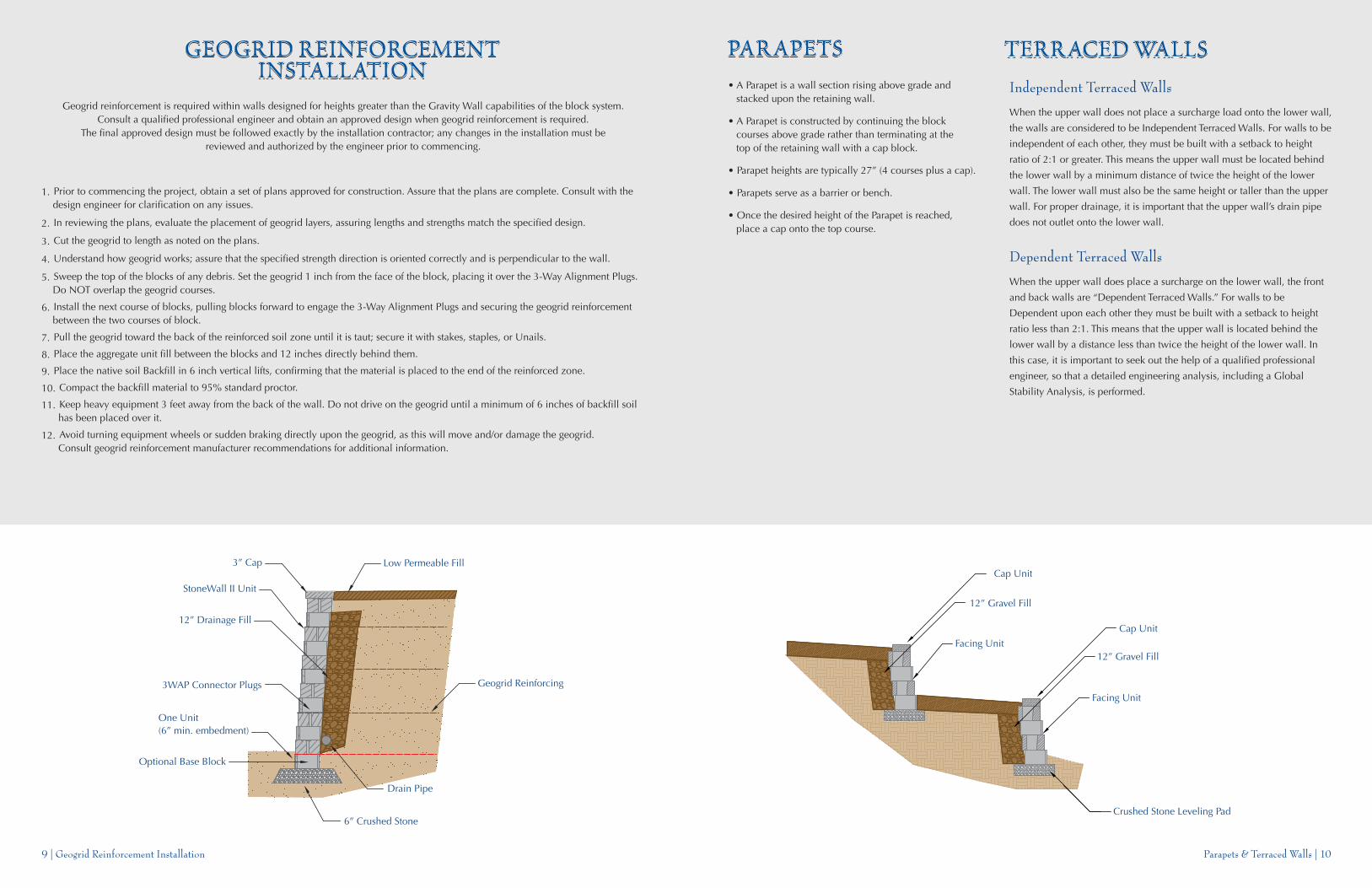
• A Parapet is a wall section rising above grade andstacked upon the retaining wall.
• A Parapet is constructed by continuing the blockcourses above grade rather than terminating at thetop of the retaining wall with a cap block.
• Parapet heights are typically 27” (4 courses plus a cap).
• Parapets serve as a barrier or bench.
• Once the desired height of the Parapet is reached,place a cap onto the top course.
Geogrid reinforcement is required within walls designed for heights greater than the Gravity Wall capabilities of the block system.Consult a qualified professional engineer and obtain an approved design when geogrid reinforcement is required.
The final approved design must be followed exactly by the installation contractor; any changes in the installation must bereviewed and authorized by the engineer prior to commencing.
Independent Terraced Walls
When the upper wall does not place a surcharge load onto the lower wall,
the walls are considered to be Independent Terraced Walls. For walls to be
independent of each other, they must be built with a setback to height
ratio of 2:1 or greater. This means the upper wall must be located behind
the lower wall by a minimum distance of twice the height of the lower
wall. The lower wall must also be the same height or taller than the upper
wall. For proper drainage, it is important that the upper wall’s drain pipe
does not outlet onto the lower wall.
Dependent Terraced Walls
When the upper wall does place a surcharge on the lower wall, the front
and back walls are “Dependent Terraced Walls.” For walls to be
Dependent upon each other they must be built with a setback to height
ratio less than 2:1. This means that the upper wall is located behind the
lower wall by a distance less than twice the height of the lower wall. In
this case, it is important to seek out the help of a qualified professional
engineer, so that a detailed engineering analysis, including a Global
Stability Analysis, is performed.
1. Prior to commencing the project, obtain a set of plans approved for construction. Assure that the plans are complete. Consult with thedesign engineer for clarification on any issues.
2. In reviewing the plans, evaluate the placement of geogrid layers, assuring lengths and strengths match the specified design.
3. Cut the geogrid to length as noted on the plans.
4. Understand how geogrid works; assure that the specified strength direction is oriented correctly and is perpendicular to the wall.
5. Sweep the top of the blocks of any debris. Set the geogrid 1 inch from the face of the block, placing it over the 3-Way Alignment Plugs.Do NOT overlap the geogrid courses.
6. Install the next course of blocks, pulling blocks forward to engage the 3-Way Alignment Plugs and securing the geogrid reinforcementbetween the two courses of block.
7. Pull the geogrid toward the back of the reinforced soil zone until it is taut; secure it with stakes, staples, or Unails.
8. Place the aggregate unit fill between the blocks and 12 inches directly behind them.
9. Place the native soil Backfill in 6 inch vertical lifts, confirming that the material is placed to the end of the reinforced zone.
10. Compact the backfill material to 95% standard proctor.
11. Keep heavy equipment 3 feet away from the back of the wall. Do not drive on the geogrid until a minimum of 6 inches of backfill soilhas been placed over it.
12. Avoid turning equipment wheels or sudden braking directly upon the geogrid, as this will move and/or damage the geogrid.Consult geogrid reinforcement manufacturer recommendations for additional information.
6” Crushed Stone
3” Cap
12” Drainage Fill
StoneWall II Unit
Drain Pipe
Geogrid Reinforcing
Low Permeable Fill
One Unit(6” min. embedment)
3WAP Connector Plugs
Optional Base Block
Facing Unit
Cap Unit
Facing Unit
Crushed Stone Leveling Pad
Cap Unit
12” Gravel Fill
12” Gravel Fill
Column Kit
15 Rec 6 Rec
6 Rec 15 Rec
21 in
6 Rec 15 Rec
15 Rec 6 Rec
21 in
21in
21in
Column Kit
B
C
G
E
E
F
F
H
H
G
Column Kit
B
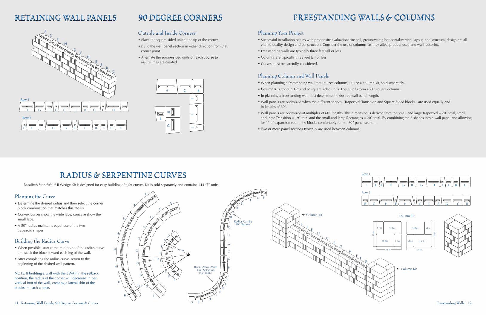
Row 1
C E F H G B G H F E B C
Row 2
B G H HF F E EC CG B
Freestanding Walls | 1211 | Retaining Wall Panels, 90 Degree Corners & Curves
B
C
G
E
E
F
F
H
H
CB
Row 1
CE FH G BG HF EC
Row 2
C EF H G BHF E CB
Outside and Inside Corners:• Place the square-sided unit at the tip of the corner.
• Build the wall panel section in either direction from thatcorner point.
• Alternate the square-sided units on each course toassure lines are created.
BGH
HF
E
B
E
G
Planning the Curve• Determine the desired radius and then select the corner
block combination that matches this radius.
• Convex curves show the wide face, concave show thesmall face.
• A 50” radius maintains equal use of the twotrapezoid shapes.
Building the Radius Curve• When possible, start at the mid-point of the radius curve
and stack the block toward each leg of the wall.
• After completing the radius curve, return to thebeginning of the desired wall pattern.
NOTE: If building a wall with the 3WAP in the setbackposition, the radius of the corner will decrease 1” pervertical foot of the wall, creating a lateral shift of theblocks on each course.
Planning Your Project• Successful installation begins with proper site evaluation: site soil, groundwater, horizontal/vertical layout, and structural design are all
vital to quality design and construction. Consider the use of columns, as they affect product used and wall footprint.
• Freestanding walls are typically three feet tall or less.
• Columns are typically three feet tall or less.
• Curves must be carefully considered.
Planning Column and Wall Panels• When planning a freestanding wall that utilizes columns, utilize a column kit, sold separately.
• Column Kits contain 15” and 6” square sided units. These units form a 21” square column.
• In planning a freestanding wall, first determine the desired wall panel length.
• Wall panels are optimized when the different shapes - Trapezoid, Transition and Square Sided blocks - are used equally andin lengths of 60’.
• Wall panels are optimized at multiples of 60” lengths. This dimension is derived from the small and large Trapezoid = 20” total, smalland large Transition = 19” total and the small and large Rectangles = 20” total. By combining the 3 shapes into a wall panel and allowingfor 1” of expansion room, the blocks comfortably form a 60” panel section.
• Two or more panel sections typically are used between columns.
73 in
51 in
27 in
H
H G
G
G
G
G
G
G
G
G
G
H
H
H
H
H
H
FF
F
F
F
F
F
F
FF
Radius Varies WithUnit Selection
(55” min.)
Radius Can Be90° Or Less
G B FH
F
F
F
E
E
E
H
G
C
G
H
G
C
E
B
B
B
C
CH
Basalite’s StoneWall® II Wedge Kit is designed for easy building of tight curves. Kit is sold separately and contains 144 “F” units.

Stairways & Sitting Areas | 1413 | Fire Pits & Planters/Fountains
Row 1
BRow 2
Column KitColumn Kit
FH
FG
GC
BC
EH
E
BF
HF
GG
CB
CE
HE
BFHF G G CBC EHE
GGB BH HE ECCFF
EC
FH
GB
GH
E
C
FB B
GH
F FG
CB
CE
H
Row 1
C E F H G B G H F E B C
Row 2
B G H HF F E EC CG B
Column Kit
Column Kit
BC
GE
CE
F
FH
HG
GFGFGFG
GGGF
FFF
GGGGGG
GGG
FFFFFF
C
E
H
G
B
G
F
B
CC
B
B
E
E
H
H
F
F
G
B
B
B
CC
B
B
BB
C
C
B
B
BG
G
G
FH
F
F
H
H
E
B
B
E
E
C
C
CB
15”
Ø35”
61”
Fire Pit Kits are sold separately. Available as a 15” tall kit (two courses plus cap) or a 21” tall kit (three courses plus cap).