Embed Size (px)
Citation preview
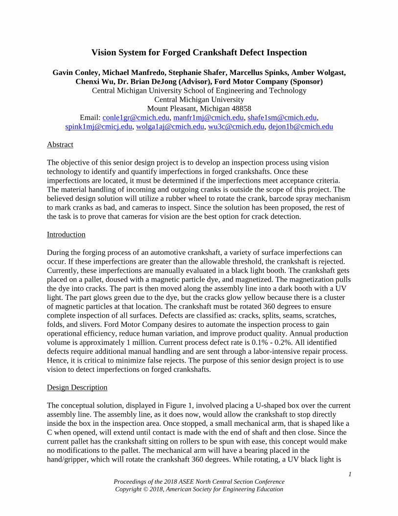
1
Proceedings of the 2018 ASEE North Central Section Conference
Copyright © 2018, American Society for Engineering Education
Vision System for Forged Crankshaft Defect Inspection
Gavin Conley, Michael Manfredo, Stephanie Shafer, Marcellus Spinks, Amber Wolgast,
Chenxi Wu, Dr. Brian DeJong (Advisor), Ford Motor Company (Sponsor)
Central Michigan University School of Engineering and Technology
Central Michigan University
Mount Pleasant, Michigan 48858
Email: [email protected], [email protected], [email protected],
[email protected], [email protected], [email protected], [email protected]
Abstract
The objective of this senior design project is to develop an inspection process using vision
technology to identify and quantify imperfections in forged crankshafts. Once these
imperfections are located, it must be determined if the imperfections meet acceptance criteria.
The material handling of incoming and outgoing cranks is outside the scope of this project. The
believed design solution will utilize a rubber wheel to rotate the crank, barcode spray mechanism
to mark cranks as bad, and cameras to inspect. Since the solution has been proposed, the rest of
the task is to prove that cameras for vision are the best option for crack detection.
Introduction
During the forging process of an automotive crankshaft, a variety of surface imperfections can
occur. If these imperfections are greater than the allowable threshold, the crankshaft is rejected.
Currently, these imperfections are manually evaluated in a black light booth. The crankshaft gets
placed on a pallet, doused with a magnetic particle dye, and magnetized. The magnetization pulls
the dye into cracks. The part is then moved along the assembly line into a dark booth with a UV
light. The part glows green due to the dye, but the cracks glow yellow because there is a cluster
of magnetic particles at that location. The crankshaft must be rotated 360 degrees to ensure
complete inspection of all surfaces. Defects are classified as: cracks, splits, seams, scratches,
folds, and slivers. Ford Motor Company desires to automate the inspection process to gain
operational efficiency, reduce human variation, and improve product quality. Annual production
volume is approximately 1 million. Current process defect rate is 0.1% - 0.2%. All identified
defects require additional manual handling and are sent through a labor-intensive repair process.
Hence, it is critical to minimize false rejects. The purpose of this senior design project is to use
vision to detect imperfections on forged crankshafts.
Design Description
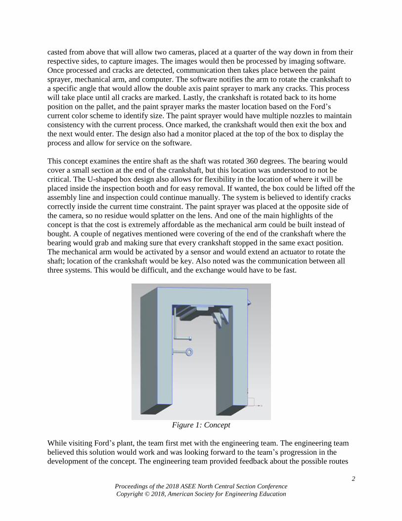
The conceptual solution, displayed in Figure 1, involved placing a U-shaped box over the current
assembly line. The assembly line, as it does now, would allow the crankshaft to stop directly
inside the box in the inspection area. Once stopped, a small mechanical arm, that is shaped like a
C when opened, will extend until contact is made with the end of shaft and then close. Since the
current pallet has the crankshaft sitting on rollers to be spun with ease, this concept would make
no modifications to the pallet. The mechanical arm will have a bearing placed in the
hand/gripper, which will rotate the crankshaft 360 degrees. While rotating, a UV black light is
2
Proceedings of the 2018 ASEE North Central Section Conference
Copyright © 2018, American Society for Engineering Education
casted from above that will allow two cameras, placed at a quarter of the way down in from their
respective sides, to capture images. The images would then be processed by imaging software.
Once processed and cracks are detected, communication then takes place between the paint
sprayer, mechanical arm, and computer. The software notifies the arm to rotate the crankshaft to
a specific angle that would allow the double axis paint sprayer to mark any cracks. This process
will take place until all cracks are marked. Lastly, the crankshaft is rotated back to its home
position on the pallet, and the paint sprayer marks the master location based on the Ford’s
current color scheme to identify size. The paint sprayer would have multiple nozzles to maintain
consistency with the current process. Once marked, the crankshaft would then exit the box and
the next would enter. The design also had a monitor placed at the top of the box to display the
process and allow for service on the software.
This concept examines the entire shaft as the shaft was rotated 360 degrees. The bearing would
cover a small section at the end of the crankshaft, but this location was understood to not be
critical. The U-shaped box design also allows for flexibility in the location of where it will be
placed inside the inspection booth and for easy removal. If wanted, the box could be lifted off the
assembly line and inspection could continue manually. The system is believed to identify cracks
correctly inside the current time constraint. The paint sprayer was placed at the opposite side of
the camera, so no residue would splatter on the lens. And one of the main highlights of the
concept is that the cost is extremely affordable as the mechanical arm could be built instead of
bought. A couple of negatives mentioned were covering of the end of the crankshaft where the
bearing would grab and making sure that every crankshaft stopped in the same exact position.
The mechanical arm would be activated by a sensor and would extend an actuator to rotate the
shaft; location of the crankshaft would be key. Also noted was the communication between all
three systems. This would be difficult, and the exchange would have to be fast.
Figure 1: Concept
While visiting Ford’s plant, the team first met with the engineering team. The engineering team
believed this solution would work and was looking forward to the team’s progression in the
development of the concept. The engineering team provided feedback about the possible routes

3
Proceedings of the 2018 ASEE North Central Section Conference
Copyright © 2018, American Society for Engineering Education
of marking and rotation, which the team would consider for the final design. Next, the team also
met with the Plant Manager of two plants; one plant would be affected by this project, and the
other plant that housed the engineering team. The plant manager was impressed with the
progress and provided feedback to the team. The plant manager also suggested his preference, a
collaborative robot, but assured this concept would also be viable.
Overall, there were several key customer inputs that slightly changed the concept. First, was to
use a rubber wheel attached to a servomechanism to rotate the crankshaft in place of the robotic
gripper. Second, a barcode would be sprayed on each defective part linking the image defects to
the specific area of the crank through software. The barcode would be used in place of a complex
robotic marking system. Figure 2 shows the final CAD model of the concept.
Figure 2: Final CAD Model
Manufacturing
Figure 2 above shows the geometric design of the model. The dimensions of the model were
based on measurements of the existing assembly line and pallet provided by Ford. The legs of
the design were made high enough to cover the span from the floor to the bottom of the UV light,
roughly 55 and ½ inches. The legs of the box were constructed at a height of 65 inches to
account for the 55 and ½ inches from the ground, the UV light height, and the hooks attached to
hang the UV light. The length of the pallet was 20 inches; therefore, the length of the structure
had to be greater than 20 inches. The structure length was set at 30 inches for two reasons. One,
the pallet length was 20 inches giving a reasonable amount of 5 inches left over on each side.

4
Proceedings of the 2018 ASEE North Central Section Conference
Copyright © 2018, American Society for Engineering Education
Secondly, the UV light currently used was actually two connected UV lights. Each UV light
spanned around 14 inches, so the length of the structure was set at 30 inches to compensate for
the two UV lights length together. The UV light was placed in the middle of the structure with
about 1 inch left on each end. The width of the structure was 27 inches. The current assembly
line at the plant is 23 inches wide. The structure was made just greater than this width to fit over
the assembly line, but close enough so the rub wheel could reach with ease. The width may have
to be modified based on possible structures and obstacles in the way near the bottom of the
assembly line.
From there, the monitor on the side was placed at about 4.5 feet with the keyboard around 3.3
feet. These dimensions can easily be changed if needed. The UV light was positioned halfway
between the widths of the structure at the top. The UV light is hung from hooks that clamp on to
provided clips from the UV light assembly kit. Cameras were mounted about 4.8 feet from the
ground to cover all areas of the crankshaft. If changed, the bar mounting the cameras would be in
roughly the same place; however, instead of brackets directly mounted to the bar, a possible
camera mount would be used to allow the camera to be positioned at different angles. This
mount is similar to how cameras are used in the entertainment business. The rub wheel and servo
mechanism were placed 3 inches in from the front of the structure and about 12 inches into the
middle of the structure. A plate was made so that the rub wheel could be directly dropped by a
pneumatic cylinder actuator and touch the exact cylinder location on the shaft. This placement
will have to be tested once the structure is assembled. The spray gun was placed 6 inches from
the back of the assembly, so the barcode could be distributed on the end of the shaft. The spray
gun range is not entirely known and will require testing, so the internal distance into the structure
was an estimate as of now. This concludes the reasoning behind all dimensions of the assembly
in Figure 2.
Project Scope
In the beginning of the project, Ford’s expectation was for the team to design a production ready
integrated camera system that could detect and mark defects in a crankshaft. The requirements of
this design included; must inspect and mark crankshaft (if defective) within 12 seconds, fit
within the current assembly line, and pay off in 2 years. Over the past several months, the team
has made many trips down to both plants to discuss the best possible way to reach these goals.
There have been many meetings with camera companies, Cognex and Keyence, as well as
integrative camera companies to determine multiple aspects of the design. This includes camera
location, type of camera, rotation of the crankshaft, and marking system. Through research and
knowledge gained from these meetings, the group was able to decide on a concept. Not only was
it the most feasible, but it also matched the customer needs. Unfortunately, as the project made
progress, it seemed more and more unlikely that the final product by May would be production
ready. Meeting with Ford again, it was discussed that it was of best interest to narrow the scope
of the project. The customer, for now, wants the focus to be solely on the vision rather than an
integrative system. With this scope, the team would neglect rotation, marking, and integration
into their current plant. This change affected all previous information; however, the team wanted
to keep all information for following groups who deal with this project. The new goal is to now
have proof of concept of vision.
5
Proceedings of the 2018 ASEE North Central Section Conference
Copyright © 2018, American Society for Engineering Education
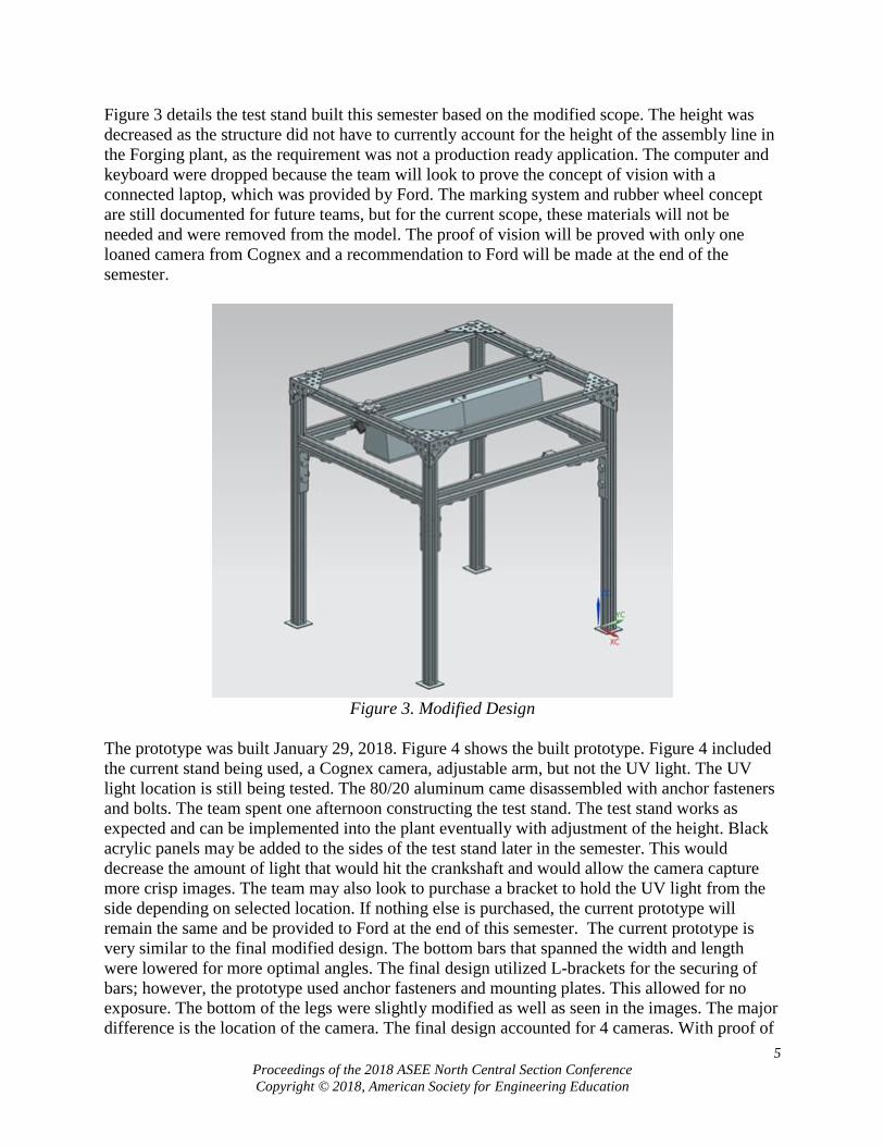
Figure 3 details the test stand built this semester based on the modified scope. The height was
decreased as the structure did not have to currently account for the height of the assembly line in
the Forging plant, as the requirement was not a production ready application. The computer and
keyboard were dropped because the team will look to prove the concept of vision with a
connected laptop, which was provided by Ford. The marking system and rubber wheel concept
are still documented for future teams, but for the current scope, these materials will not be
needed and were removed from the model. The proof of vision will be proved with only one
loaned camera from Cognex and a recommendation to Ford will be made at the end of the
semester.
Figure 3. Modified Design
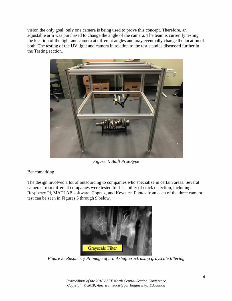
The prototype was built January 29, 2018. Figure 4 shows the built prototype. Figure 4 included
the current stand being used, a Cognex camera, adjustable arm, but not the UV light. The UV
light location is still being tested. The 80/20 aluminum came disassembled with anchor fasteners
and bolts. The team spent one afternoon constructing the test stand. The test stand works as
expected and can be implemented into the plant eventually with adjustment of the height. Black
acrylic panels may be added to the sides of the test stand later in the semester. This would
decrease the amount of light that would hit the crankshaft and would allow the camera capture
more crisp images. The team may also look to purchase a bracket to hold the UV light from the
side depending on selected location. If nothing else is purchased, the current prototype will
remain the same and be provided to Ford at the end of this semester. The current prototype is
very similar to the final modified design. The bottom bars that spanned the width and length
were lowered for more optimal angles. The final design utilized L-brackets for the securing of
bars; however, the prototype used anchor fasteners and mounting plates. This allowed for no
exposure. The bottom of the legs were slightly modified as well as seen in the images. The major
difference is the location of the camera. The final design accounted for 4 cameras. With proof of
6
Proceedings of the 2018 ASEE North Central Section Conference
Copyright © 2018, American Society for Engineering Education
vision the only goal, only one camera is being used to prove this concept. Therefore, an
adjustable arm was purchased to change the angle of the camera. The team is currently testing
the location of the light and camera at different angles and may eventually change the location of
both. The testing of the UV light and camera in relation to the test stand is discussed further in
the Testing section.
Figure 4. Built Prototype
Benchmarking
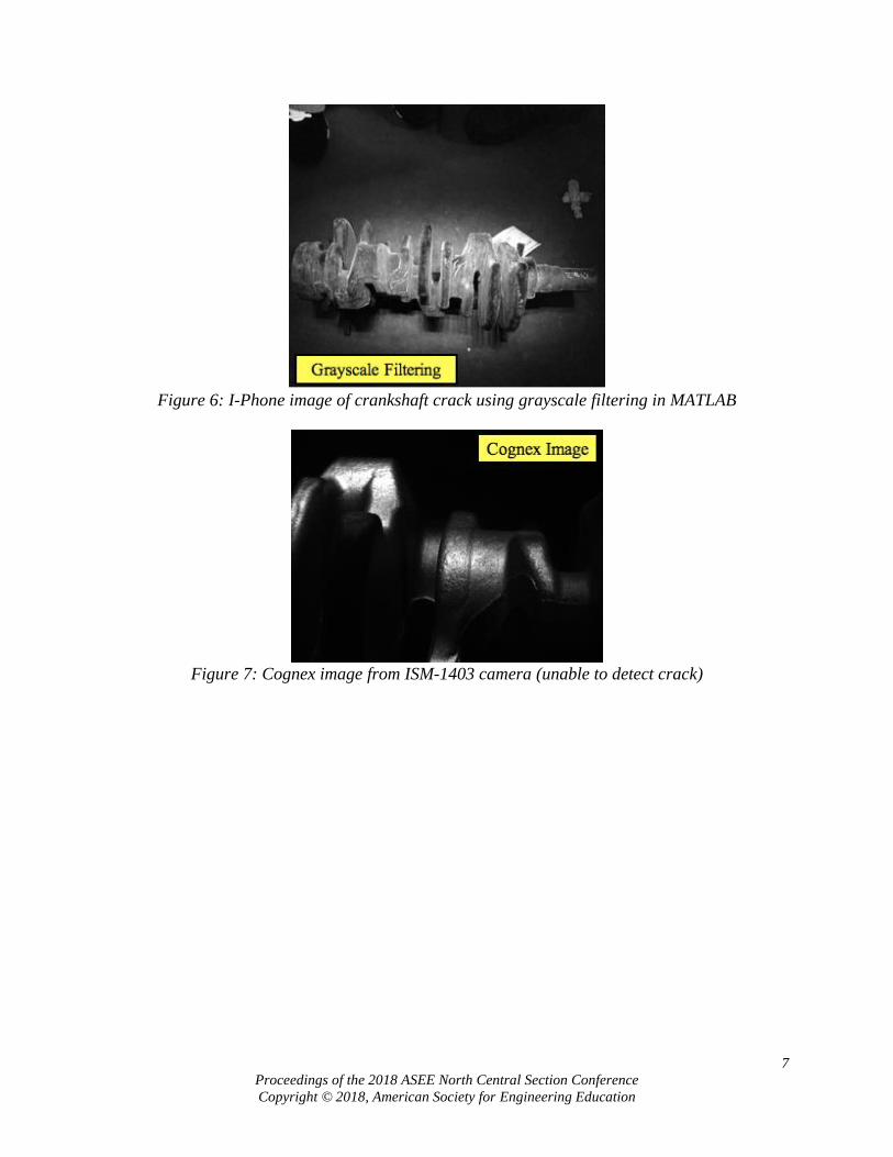
The design involved a lot of outsourcing to companies who specialize in certain areas. Several
cameras from different companies were tested for feasibility of crack detection, including:
Raspberry Pi, MATLAB software, Cognex, and Keyence. Photos from each of the three camera
test can be seen in Figures 5 through 9 below.
Figure 5: Raspberry Pi image of crankshaft crack using grayscale filtering
7
Proceedings of the 2018 ASEE North Central Section Conference
Copyright © 2018, American Society for Engineering Education
Figure 6: I-Phone image of crankshaft crack using grayscale filtering in MATLAB
Figure 7: Cognex image from ISM-1403 camera (unable to detect crack)
8
Proceedings of the 2018 ASEE North Central Section Conference
Copyright © 2018, American Society for Engineering Education
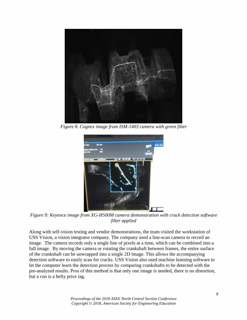
Figure 8. Cognex image from ISM-1403 camera with green filter
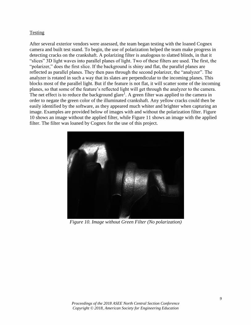
Figure 9: Keyence image from XG-H500M camera demonstration with crack detection software
filter applied
Along with self-vision testing and vendor demonstrations, the team visited the workstation of
USS Vision, a vision integrator company. The company used a line-scan camera to record an
image. The camera records only a single line of pixels at a time, which can be combined into a
full image. By moving the camera or rotating the crankshaft between frames, the entire surface
of the crankshaft can be unwrapped into a single 2D image. This allows the accompanying
detection software to easily scan for cracks. USS Vision also used machine learning software to
let the computer learn the detection process by comparing crankshafts to be detected with the
pre-analyzed results. Pros of this method is that only one image is needed, there is no distortion,
but a con is a hefty price tag.
9
Proceedings of the 2018 ASEE North Central Section Conference
Copyright © 2018, American Society for Engineering Education
Testing
After several exterior vendors were assessed, the team began testing with the loaned Cognex
camera and built test stand. To begin, the use of polarization helped the team make progress in
detecting cracks on the crankshaft. A polarizing filter is analogous to slatted blinds, in that it
“slices” 3D light waves into parallel planes of light. Two of these filters are used. The first, the
“polarizer,” does the first slice. If the background is shiny and flat, the parallel planes are
reflected as parallel planes. They then pass through the second polarizer, the “analyzer”. The
analyzer is rotated in such a way that its slates are perpendicular to the incoming planes. This
blocks most of the parallel light. But if the feature is not flat, it will scatter some of the incoming
planes, so that some of the feature’s reflected light will get through the analyzer to the camera.
The net effect is to reduce the background glare1. A green filter was applied to the camera in
order to negate the green color of the illuminated crankshaft. Any yellow cracks could then be
easily identified by the software, as they appeared much whiter and brighter when capturing an
image. Examples are provided below of images with and without the polarization filter. Figure
10 shows an image without the applied filter, while Figure 11 shows an image with the applied
filter. The filter was loaned by Cognex for the use of this project.
Figure 10. Image without Green Filter (No polarization)
10
Proceedings of the 2018 ASEE North Central Section Conference
Copyright © 2018, American Society for Engineering Education
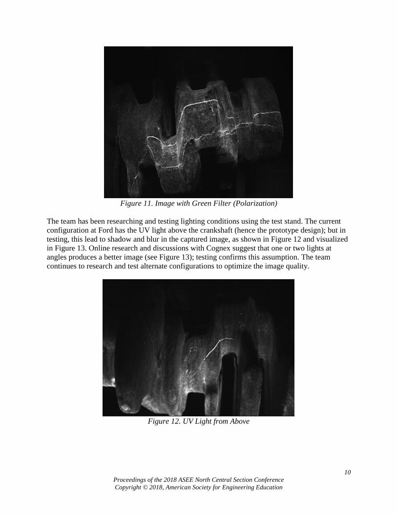
Figure 11. Image with Green Filter (Polarization)
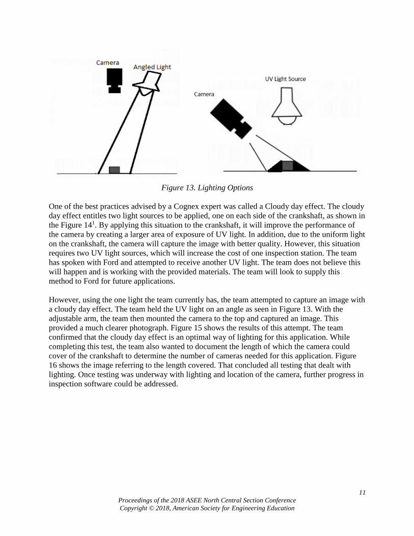
The team has been researching and testing lighting conditions using the test stand. The current
configuration at Ford has the UV light above the crankshaft (hence the prototype design); but in
testing, this lead to shadow and blur in the captured image, as shown in Figure 12 and visualized
in Figure 13. Online research and discussions with Cognex suggest that one or two lights at
angles produces a better image (see Figure 13); testing confirms this assumption. The team
continues to research and test alternate configurations to optimize the image quality.
Figure 12. UV Light from Above
11
Proceedings of the 2018 ASEE North Central Section Conference
Copyright © 2018, American Society for Engineering Education
Figure 13. Lighting Options
One of the best practices advised by a Cognex expert was called a Cloudy day effect. The cloudy
day effect entitles two light sources to be applied, one on each side of the crankshaft, as shown in
the Figure 141. By applying this situation to the crankshaft, it will improve the performance of
the camera by creating a larger area of exposure of UV light. In addition, due to the uniform light
on the crankshaft, the camera will capture the image with better quality. However, this situation
requires two UV light sources, which will increase the cost of one inspection station. The team
has spoken with Ford and attempted to receive another UV light. The team does not believe this
will happen and is working with the provided materials. The team will look to supply this
method to Ford for future applications.
However, using the one light the team currently has, the team attempted to capture an image with
a cloudy day effect. The team held the UV light on an angle as seen in Figure 13. With the
adjustable arm, the team then mounted the camera to the top and captured an image. This
provided a much clearer photograph. Figure 15 shows the results of this attempt. The team
confirmed that the cloudy day effect is an optimal way of lighting for this application. While
completing this test, the team also wanted to document the length of which the camera could
cover of the crankshaft to determine the number of cameras needed for this application. Figure
16 shows the image referring to the length covered. That concluded all testing that dealt with
lighting. Once testing was underway with lighting and location of the camera, further progress in
inspection software could be addressed.

12
Proceedings of the 2018 ASEE North Central Section Conference
Copyright © 2018, American Society for Engineering Education
Figure 14. Cloudy Day Lighting Scheme
Figure 15. One-half Cloudy Day Effect

13
Proceedings of the 2018 ASEE North Central Section Conference
Copyright © 2018, American Society for Engineering Education
Figure 16. Optimal Length of Crankshaft Covered
Software Progress
During benchmarking, Keyence had the most promising software to detect cracks in a forged
crankshaft at the initial demonstration. With that thought, the team still pursued other exterior
camera vendors to keep options open. Cognex was able to provide the team with a filter and
more of an in-depth demo of the software. Not only did Cognex show the ability to see a crack
with a green filter, Cognex also showed the team a user-friendly software and interface.
The current progress of the team is shown below. A Cognex monochrome area camera was
pursued for testing because it was loaned to the team for education purposes as opposed to
purchasing a camera from another vendor. The Cognex software used is In-Sight Explorer 5.5
and offers the ability to detect cracks through various tools. The two methods that provide the
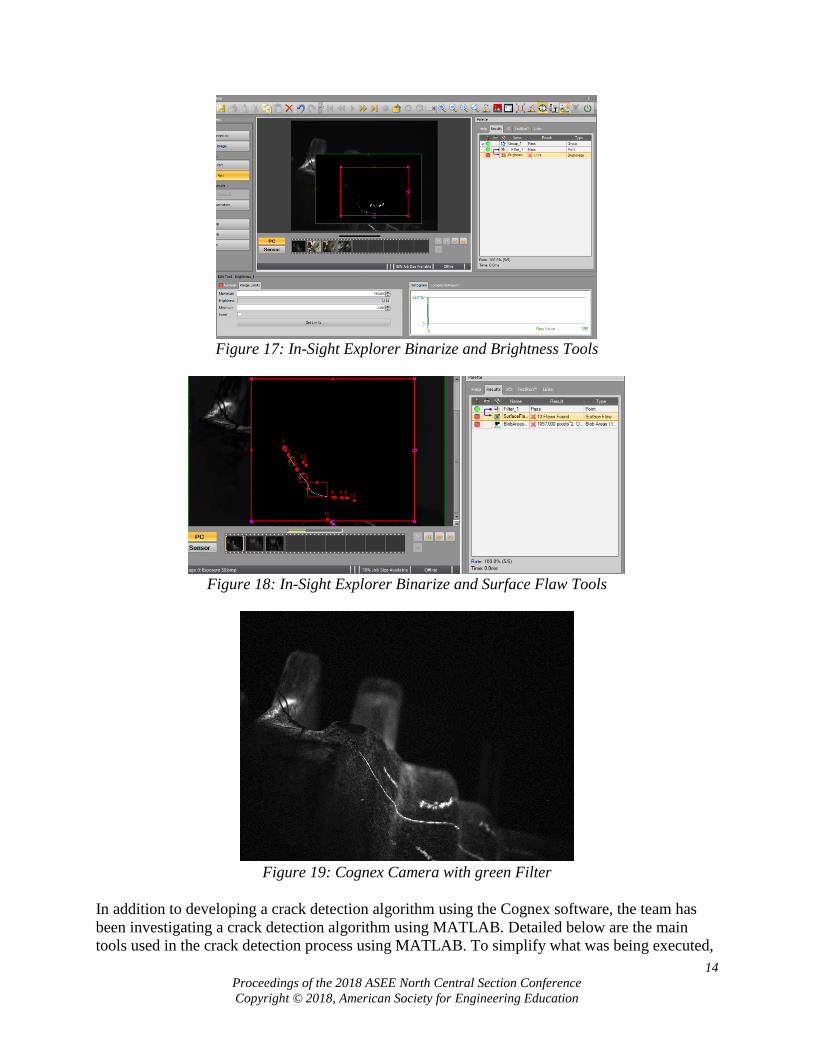
best results are shown. Figure 17 shows an image applied with a binarize filter. This filter works
by converting all pixels below a set threshold to black (0) and above the threshold to white (255).
A brightness tool was then ran and provided that the image contained a crack. The brightness
tool averages out the brightness of the pixels in the window and can be set with minimums and
maximums. If the average brightness was 0, meaning all black, there would be no crack present
and the part would pass. If the average brightness was anything higher than 0, meaning some
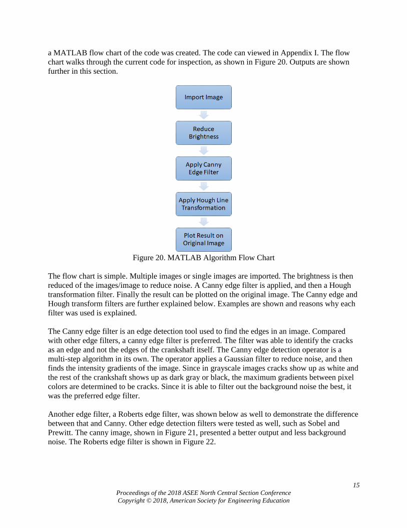
white present, then there must be a crack or flaw present and the part would fail. Figure 18 shows
the results of a second tool. Again, a binarize filter was used on a captured image, then a tool
called surface defects was used to find the crack and output that 13 flaws were present. The
surface defect tool works by finding a white pixel, and then grouping it as a flaw if the pixel next
to it has a maximum contrast of ±20 and so on. The number of flaws can be set to say which
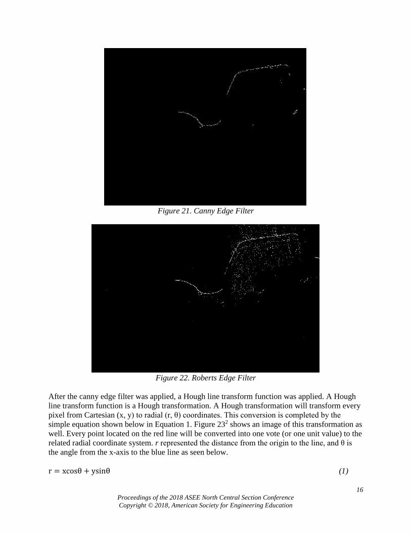
amount of flaws triggers a crack, 13 triggered a crack in Figure 18. And lastly, the original
captured image from the Cognex camera was included in Figure 19. The team is currently
looking to use several tools to find cracks contained in one job. Then, depending on how many
tools pass/fail the crankshaft, the job will determine if a crack is present.
14
Proceedings of the 2018 ASEE North Central Section Conference
Copyright © 2018, American Society for Engineering Education
Figure 17: In-Sight Explorer Binarize and Brightness Tools
Figure 18: In-Sight Explorer Binarize and Surface Flaw Tools
Figure 19: Cognex Camera with green Filter
In addition to developing a crack detection algorithm using the Cognex software, the team has
been investigating a crack detection algorithm using MATLAB. Detailed below are the main
tools used in the crack detection process using MATLAB. To simplify what was being executed,
15
Proceedings of the 2018 ASEE North Central Section Conference
Copyright © 2018, American Society for Engineering Education
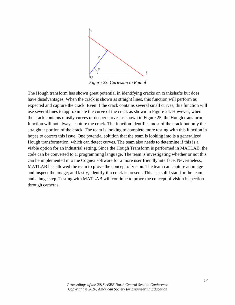
a MATLAB flow chart of the code was created. The code can viewed in Appendix I. The flow
chart walks through the current code for inspection, as shown in Figure 20. Outputs are shown
further in this section.
Figure 20. MATLAB Algorithm Flow Chart
The flow chart is simple. Multiple images or single images are imported. The brightness is then
reduced of the images/image to reduce noise. A Canny edge filter is applied, and then a Hough
transformation filter. Finally the result can be plotted on the original image. The Canny edge and
Hough transform filters are further explained below. Examples are shown and reasons why each
filter was used is explained.
The Canny edge filter is an edge detection tool used to find the edges in an image. Compared
with other edge filters, a canny edge filter is preferred. The filter was able to identify the cracks
as an edge and not the edges of the crankshaft itself. The Canny edge detection operator is a
multi-step algorithm in its own. The operator applies a Gaussian filter to reduce noise, and then
finds the intensity gradients of the image. Since in grayscale images cracks show up as white and
the rest of the crankshaft shows up as dark gray or black, the maximum gradients between pixel
colors are determined to be cracks. Since it is able to filter out the background noise the best, it
was the preferred edge filter.
Another edge filter, a Roberts edge filter, was shown below as well to demonstrate the difference
between that and Canny. Other edge detection filters were tested as well, such as Sobel and
Prewitt. The canny image, shown in Figure 21, presented a better output and less background
noise. The Roberts edge filter is shown in Figure 22.
16
Proceedings of the 2018 ASEE North Central Section Conference
Copyright © 2018, American Society for Engineering Education
Figure 21. Canny Edge Filter
Figure 22. Roberts Edge Filter
After the canny edge filter was applied, a Hough line transform function was applied. A Hough
line transform function is a Hough transformation. A Hough transformation will transform every
pixel from Cartesian (x, y) to radial (r, θ) coordinates. This conversion is completed by the
simple equation shown below in Equation 1. Figure 232 shows an image of this transformation as
well. Every point located on the red line will be converted into one vote (or one unit value) to the
related radial coordinate system. r represented the distance from the origin to the line, and θ is
the angle from the x-axis to the blue line as seen below.
r = xcosθ + ysinθ (1)
17
Proceedings of the 2018 ASEE North Central Section Conference
Copyright © 2018, American Society for Engineering Education
Figure 23. Cartesian to Radial
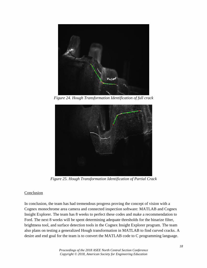
The Hough transform has shown great potential in identifying cracks on crankshafts but does
have disadvantages. When the crack is shown as straight lines, this function will perform as
expected and capture the crack. Even if the crack contains several small curves, this function will
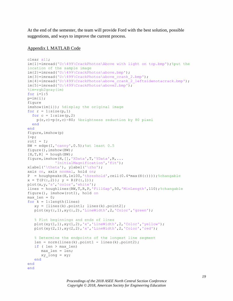
use several lines to approximate the curve of the crack as shown in Figure 24. However, when
the crack contains mostly curves or deeper curves as shown in Figure 25, the Hough transform
function will not always capture the crack. The function identifies most of the crack but only the
straighter portion of the crack. The team is looking to complete more testing with this function in
hopes to correct this issue. One potential solution that the team is looking into is a generalized
Hough transformation, which can detect curves. The team also needs to determine if this is a
viable option for an industrial setting. Since the Hough Transform is performed in MATLAB, the
code can be converted to C programming language. The team is investigating whether or not this
can be implemented into the Cognex software for a more user friendly interface. Nevertheless,
MATLAB has allowed the team to prove the concept of vision. The team can capture an image
and inspect the image; and lastly, identify if a crack is present. This is a solid start for the team
and a huge step. Testing with MATLAB will continue to prove the concept of vision inspection
through cameras.
18
Proceedings of the 2018 ASEE North Central Section Conference
Copyright © 2018, American Society for Engineering Education
Figure 24. Hough Transformation Identification of full crack
Figure 25. Hough Transformation Identification of Partial Crack
Conclusion
In conclusion, the team has had tremendous progress proving the concept of vision with a
Cognex monochrome area camera and connected inspection software: MATLAB and Cognex
Insight Explorer. The team has 8 weeks to perfect these codes and make a recommendation to
Ford. The next 8 weeks will be spent determining adequate thresholds for the binarize filter,
brightness tool, and surface detection tools in the Cognex Insight Explorer program. The team
also plans on testing a generalized Hough transformation in MATLAB to find curved cracks. A
desire and end goal for the team is to convert the MATLAB code to C programming language.
19
Proceedings of the 2018 ASEE North Central Section Conference
Copyright © 2018, American Society for Engineering Education
At the end of the semester, the team will provide Ford with the best solution, possible
suggestions, and ways to improve the current process.
Appendix I. MATLAB Code
clear all; im{1}=imread('U:\499\CrackPhotos\Above with light on top.bmp');%put the
location of the sample image im{2}=imread('U:\499\CrackPhotos\above.bmp'); im{3}=imread('U:\499\CrackPhotos\above_crank_2.bmp'); im{4}=imread('U:\499\CrackPhotos\above_crank_2_leftsidenotacrack.bmp'); im{5}=imread('U:\499\CrackPhotos\above2.bmp'); %im=rgb2gray(im) for i=1:5 p=im{i}; figure imshow(im{i}); %display the original image for r = 1:size(p,1) for c = 1:size(p,2) p(r,c)=p(r,c)-80; %brightness reduction by 80 pixel end end figure,imshow(p) I=p; rotI = I; BW = edge(I,'canny',0.5);%at least 0.5 figure(),imshow(BW); [H,T,R] = hough(BW); figure,imshow(H,[],'XData',T,'YData',R,... 'InitialMagnification','fit'); xlabel('\theta'), ylabel('\rho'); axis on, axis normal, hold on; P = houghpeaks(H,1e100,'threshold',ceil(0.4*max(H(:))));%changable x = T(P(:,2)); y = R(P(:,1)); plot(x,y,'s','color','white'); lines = houghlines(BW,T,R,P,'FillGap',50,'MinLength',110);%changable figure(), imshow(rotI), hold on max_len = 0; for k = 1:length(lines) xy = [lines(k).point1; lines(k).point2]; plot(xy(:,1),xy(:,2),'LineWidth',2,'Color','green');
% Plot beginnings and ends of lines plot(xy(1,1),xy(1,2),'x','LineWidth',2,'Color','yellow'); plot(xy(2,1),xy(2,2),'x','LineWidth',2,'Color','red');
% Determine the endpoints of the longest line segment len = norm(lines(k).point1 - lines(k).point2); if ( len > max_len) max_len = len; xy_long = xy; end end end
20
Proceedings of the 2018 ASEE North Central Section Conference
Copyright © 2018, American Society for Engineering Education
Acknowledgements
This project was made possible with the help of Ford Motor Company and Cognex. The authors
would like to thank Ford Motor Company for providing insight, expertise, assistance, and
funding for this project. We are also grateful to Cognex for providing a camera and training on
how to use it.
Bibliography
1. Cognex Corp. (2018). In-Sight EasyBuilder Standard [Powerpoint]. Retrieved from
https://support.cognex.com/en/downloads/detail/3555/1033
2. “BW.” Hough Transform - MATLAB Hough,
www.mathworks.com/help/images/ref/hough.html?s_tid=gn_loc_drop.