Embed Size (px)
Citation preview
V I S H Ay I n T E R T E C H n O l O G y, I n C .
RESiSTORS 101
w w w . v i s h a y . c o m
InS
TR
UC
TIO
nA
l G
UID
ER
ES
IST
OR
S
V I S H Ay DA l E
V I S H Ay T H I n F I l M
V I S H Ay E l E C T R O - F I l M S ( E F I )
V I S H Ay T E C H n O
V I S H Ay A n G S T R O H M
V•II²•R
I•R
V²/R
V²/P
P/I²
√P/R
P/IV/I
P/V
P I
V R√P•R
V/R
Watts Amps
Volts Ohms
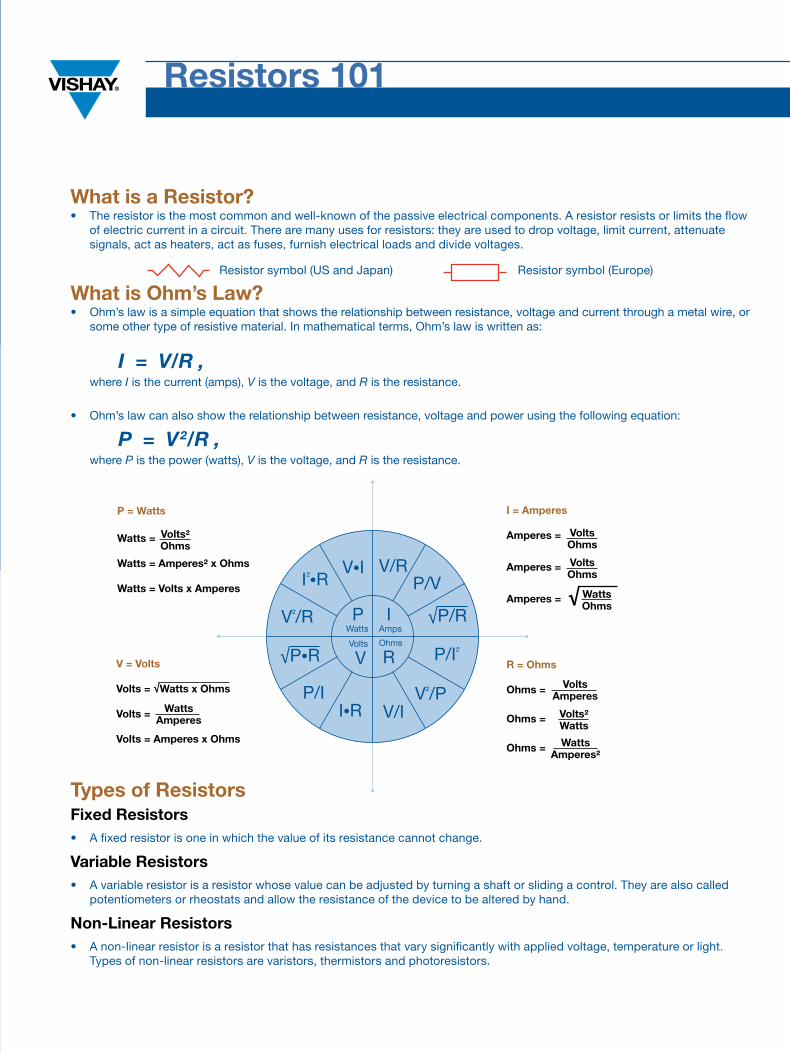
What is Ohm’s Law?• Ohm’s law is a simple equation that shows the relationship between resistance, voltage and current through a metal wire, or
some other type of resistive material. In mathematical terms, Ohm’s law is written as:
I = V/R , where I is the current (amps), V is the voltage, and R is the resistance.
• Ohm’s law can also show the relationship between resistance, voltage and power using the following equation:
P = V2/R , where P is the power (watts), V is the voltage, and R is the resistance.
Types of ResistorsFixed Resistors• A fixed resistor is one in which the value of its resistance cannot change.
variable Resistors• A variable resistor is a resistor whose value can be adjusted by turning a shaft or sliding a control. They are also called
potentiometers or rheostats and allow the resistance of the device to be altered by hand.
Non-Linear Resistors• A non-linear resistor is a resistor that has resistances that vary significantly with applied voltage, temperature or light.
Types of non-linear resistors are varistors, thermistors and photoresistors.
Amperes =
Amperes =
Amperes = √
InS
TR
UC
TIO
nA
l G
UID
ER
ES
IST
OR
S
Resistors 101
What is a Resistor?• The resistor is the most common and well-known of the passive electrical components. A resistor resists or limits the flow
of electric current in a circuit. There are many uses for resistors: they are used to drop voltage, limit current, attenuate signals, act as heaters, act as fuses, furnish electrical loads and divide voltages.
Resistor symbol (US and japan) Resistor symbol (Europe)
P = Watts i = Amperes
v = volts R = Ohms
Watts =
Watts = Amperes² x Ohms
Watts = volts x Amperes
volts = √Watts x Ohms
volts =
volts = Amperes x Ohms
Ohms =
Ohms =
Ohms =
volts²Ohms
WattsAmperes
voltsOhms
voltsOhms
WattsOhms
voltsAmperes
volts²Watts
WattsAmperes²
Resistors 101
Common Resistor TerminologyCritical Resistance value• The maximum nominal resistance value at which the rated power can be loaded without exceeding the maximum working voltage. The rated voltage is equal to the maximum working voltage in the critical resistance value.
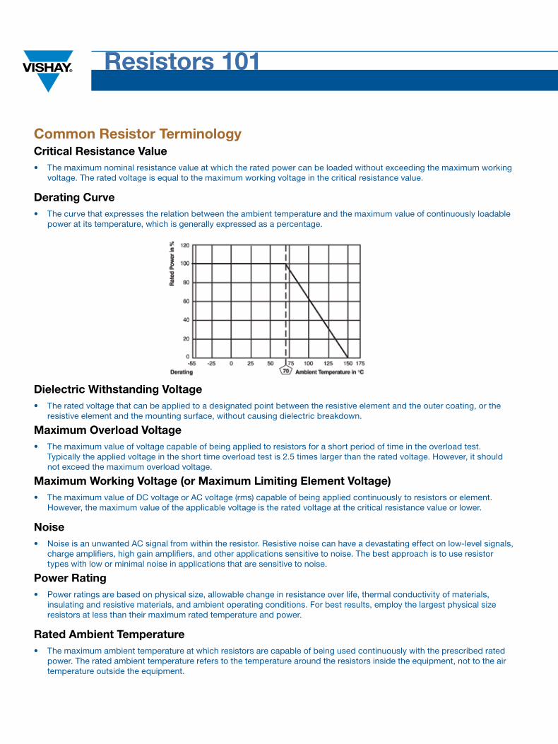
Derating Curve• The curve that expresses the relation between the ambient temperature and the maximum value of continuously loadable power at its temperature, which is generally expressed as a percentage.
Dielectric Withstanding voltage• The rated voltage that can be applied to a designated point between the resistive element and the outer coating, or the
resistive element and the mounting surface, without causing dielectric breakdown.
Maximum Overload voltage• The maximum value of voltage capable of being applied to resistors for a short period of time in the overload test.
Typically the applied voltage in the short time overload test is 2.5 times larger than the rated voltage. However, it should not exceed the maximum overload voltage.
Maximum Working voltage (or Maximum Limiting Element voltage) • The maximum value of DC voltage or AC voltage (rms) capable of being applied continuously to resistors or element. However, the maximum value of the applicable voltage is the rated voltage at the critical resistance value or lower.
Noise• noise is an unwanted AC signal from within the resistor. Resistive noise can have a devastating effect on low-level signals,
charge amplifiers, high gain amplifiers, and other applications sensitive to noise. The best approach is to use resistor types with low or minimal noise in applications that are sensitive to noise.
Power Rating• Power ratings are based on physical size, allowable change in resistance over life, thermal conductivity of materials, insulating and resistive materials, and ambient operating conditions. For best results, employ the largest physical size resistors at less than their maximum rated temperature and power.
Rated Ambient Temperature• The maximum ambient temperature at which resistors are capable of being used continuously with the prescribed rated
power. The rated ambient temperature refers to the temperature around the resistors inside the equipment, not to the air temperature outside the equipment.
TRiM
hE
RE
Common Resistor TerminologyRated Power• The maximum amount of power that can be continuously loaded to a resistor at a rated ambient temperature. network and array products have both rated power per package as well as per element.
Rated voltage• The maximum value of DC voltage or AC voltage (rms) capable of being applied continuously to resistors at the rated ambient temperature.
Reliability• Reliability is the probability that a resistor (or any other device) will perform its desired function. There are two ways of defining reliability. One is Mean Time Between Failures (MTBF) and the other is Failure Rate per 1,000 hours of operation. Both of these means of evaluating reliability must be determined with a specific group of tests and a definition of what is the end of life for a device, such as a maximum change in resistance or a catastrophic failure (short or open). Various statistical studies are used to arrive at these failure rates and large samples are tested at the maximum rated temperature with rated load for up to 10,000 hours (24 hours per day for approximately 13 months). Reliability is generally higher at lower power levels.
Resistor Tolerance• Resistor tolerance is expressed as the deviation from nominal value in percent and is measured at 25 ˚C only with no appreciable power applied. A resistor’s value will also change with applied voltage (VCR) and temperature (TCR). For networks, absolute resistor tolerance refers to the overall tolerance of the network. Ratio tolerance refers to the relationship of each resistor to the others in the package.
Stability• Stability is the change in resistance with time at a specific load, humidity level, stress, or ambient temperature. When these stresses are minimized, the better the stability.
Temperature Coefficient of Resistance (TCR also known as RTC)• TCR is expressed as the change in resistance in ppm (0.0001 %) with each degree Celsius of change in temperature. TCR is typically referenced at +25 ˚C and changes as the temperature increases (or decreases). A resistor with a TCR of 100 ppm/°C will change 0.1 % over a 10 °C change and 1 % over a 100 °C change. In the context of a resistor network, the TCR value is called the absolute TCR in that it defines the TCR of a specific resistor element. The term TCR
tracking refers to the difference in TCR between each specific resistor in a network.
Temperature Rating• Temperature rating is the maximum allowable temperature at which the resistor may be used. It is generally defined with two temperatures. For example, a resistor may be rated at full load up to +70 °C derated to no load at +125 °C. This means that with certain allowable changes in resistance over the life of the resistor, it may be operated at +70 °C at rated power. It also may be operated with temperatures in excess of +70 °C if the load is reduced, but in no case should the temperature exceed the design temperature of +125 ˚C with a combination of ambient temperature and self-heating due to the applied load.
voltage Coefficient of Resistance (vCR)• The voltage coefficient is the change in resistance with applied voltage. This is entirely different and in addition to the
effects of self-heating when power is applied. A resistor with a VCR of 100 ppm/V will change 0.1 % over a 10 V change and 1 % over a 100 V change. In the context of a resistor network, this VCR value is called the absolute VCR in that it defines the VCR of a specific resistor element. The term VCR tracking refers to the difference in VCR between each specific resistor in a network.
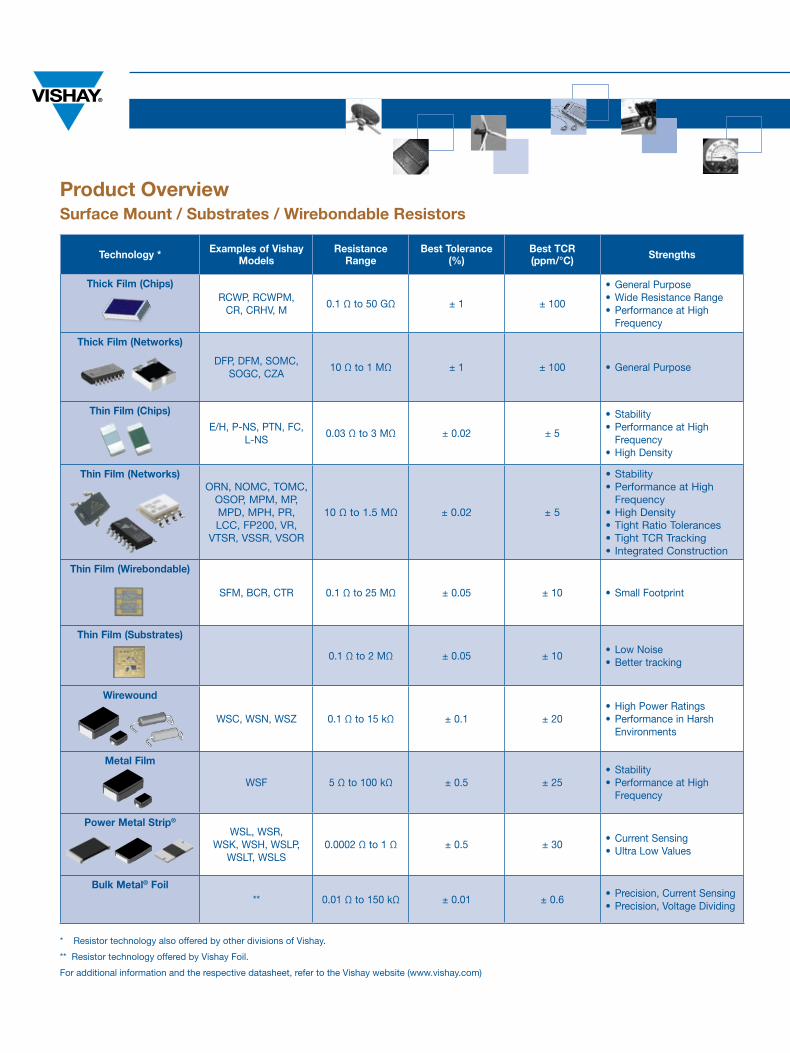
Product OverviewSurface Mount / Substrates / Wirebondable Resistors
Technology * Examples of vishay Models
Resistance Range
Best Tolerance(%)
Best TCR(ppm/°C) Strengths
Thick Film (Chips)RCWP, RCWPM,
CR, CRHV, M0.1 Ω to 50 GΩ ± 1 ± 100
• General Purpose• Wide Resistance Range• Performance at High
Frequency
Thick Film (Networks)
DFP, DFM, SOMC, SOGC, CZA
10 Ω to 1 MΩ ± 1 ± 100 • General Purpose
Thin Film (Chips)
E/H, P-nS, PTn, FC, l-nS
0.03 Ω to 3 MΩ ± 0.02 ± 5
• Stability• Performance at High
Frequency • High Density
Thin Film (Networks)ORn, nOMC, TOMC,
OSOP, MPM, MP, MPD, MPH, PR, lCC, FP200, VR,
VTSR, VSSR, VSOR
10 Ω to 1.5 MΩ ± 0.02 ± 5
• Stability• Performance at High
Frequency • High Density• Tight Ratio Tolerances• Tight TCR Tracking• Integrated Construction
Thin Film (Wirebondable)
SFM, BCR, CTR 0.1 Ω to 25 MΩ ± 0.05 ± 10 • Small Footprint
Thin Film (Substrates)
0.1 Ω to 2 MΩ ± 0.05 ± 10• low noise• Better tracking
Wirewound
WSC, WSn, WSZ 0.1 Ω to 15 kΩ ± 0.1 ± 20• High Power Ratings• Performance in Harsh
Environments
Metal Film
WSF 5 Ω to 100 kΩ ± 0.5 ± 25• Stability• Performance at High
Frequency
Power Metal Strip®
WSl, WSR,WSK, WSH, WSlP,
WSlT, WSlS0.0002 Ω to 1 Ω ± 0.5 ± 30
• Current Sensing• Ultra low Values
Bulk Metal® Foil** 0.01 Ω to 150 kΩ ± 0.01 ± 0.6
• Precision, Current Sensing• Precision, Voltage Dividing
* Resistor technology also offered by other divisions of Vishay.
** Resistor technology offered by Vishay Foil.
For additional information and the respective datasheet, refer to the Vishay website (www.vishay.com)
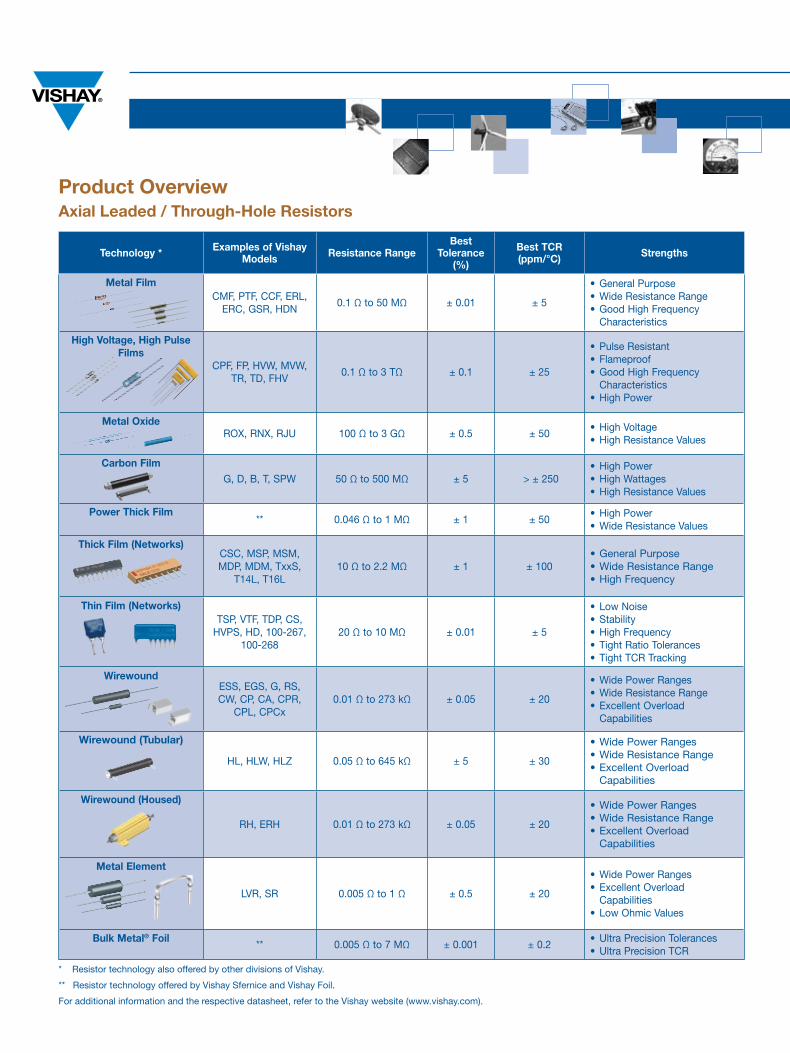
Product OverviewAxial Leaded / Through-hole Resistors
Technology * Examples of vishay Models Resistance Range
Best Tolerance
(%)
Best TCR(ppm/°C) Strengths
Metal FilmCMF, PTF, CCF, ERl,
ERC, GSR, HDn0.1 Ω to 50 MΩ ± 0.01 ± 5
• General Purpose• Wide Resistance Range• Good High Frequency
Characteristics
high voltage, high Pulse Films
CPF, FP, HVW, MVW, TR, TD, FHV
0.1 Ω to 3 TΩ ± 0.1 ± 25
• Pulse Resistant• Flameproof• Good High Frequency
Characteristics• High Power
Metal OxideROx, Rnx, RjU 100 Ω to 3 GΩ ± 0.5 ± 50
• High Voltage• High Resistance Values
Carbon FilmG, D, B, T, SPW 50 Ω to 500 MΩ ± 5 > ± 250
• High Power• High Wattages• High Resistance Values
Power Thick Film** 0.046 Ω to 1 MΩ ± 1 ± 50
• High Power• Wide Resistance Values
Thick Film (Networks)CSC, MSP, MSM, MDP, MDM, TxxS,
T14l, T16l10 Ω to 2.2 MΩ ± 1 ± 100
• General Purpose• Wide Resistance Range• High Frequency
Thin Film (Networks)TSP, VTF, TDP, CS,
HVPS, HD, 100-267, 100-268
20 Ω to 10 MΩ ± 0.01 ± 5
• low noise• Stability• High Frequency• Tight Ratio Tolerances• Tight TCR Tracking
WirewoundESS, EGS, G, RS, CW, CP, CA, CPR,
CPl, CPCx0.01 Ω to 273 kΩ ± 0.05 ± 20
• Wide Power Ranges• Wide Resistance Range• Excellent Overload
Capabilities
Wirewound (Tubular)
Hl, HlW, HlZ 0.05 Ω to 645 kΩ ± 5 ± 30
• Wide Power Ranges• Wide Resistance Range• Excellent Overload
Capabilities
Wirewound (housed)
RH, ERH 0.01 Ω to 273 kΩ ± 0.05 ± 20
• Wide Power Ranges• Wide Resistance Range• Excellent Overload
Capabilities
Metal Element
lVR, SR 0.005 Ω to 1 Ω ± 0.5 ± 20
• Wide Power Ranges• Excellent Overload
Capabilities• low Ohmic Values
Bulk Metal® Foil** 0.005 Ω to 7 MΩ ± 0.001 ± 0.2
• Ultra Precision Tolerances• Ultra Precision TCR
* Resistor technology also offered by other divisions of Vishay.
** Resistor technology offered by Vishay Sfernice and Vishay Foil.
For additional information and the respective datasheet, refer to the Vishay website (www.vishay.com).
TRiM
hE
RE
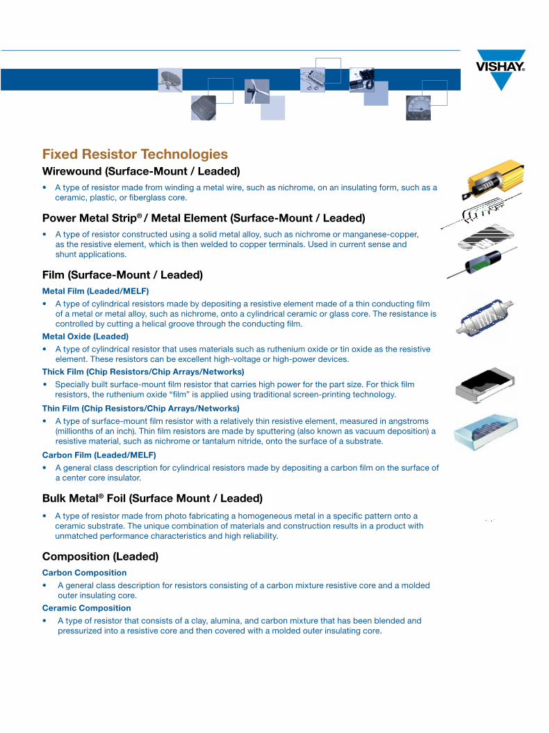
Fixed Resistor TechnologiesWirewound (Surface-Mount / Leaded)• A type of resistor made from winding a metal wire, such as nichrome, on an insulating form, such as a
ceramic, plastic, or fiberglass core.
Power Metal Strip® / Metal Element (Surface-Mount / Leaded)• A type of resistor constructed using a solid metal alloy, such as nichrome or manganese-copper,
as the resistive element, which is then welded to copper terminals. Used in current sense and shunt applications.
Film (Surface-Mount / Leaded)Metal Film (Leaded/MELF)
• A type of cylindrical resistors made by depositing a resistive element made of a thin conducting film of a metal or metal alloy, such as nichrome, onto a cylindrical ceramic or glass core. The resistance is controlled by cutting a helical groove through the conducting film.
Metal Oxide (Leaded)
• A type of cylindrical resistor that uses materials such as ruthenium oxide or tin oxide as the resistive element. These resistors can be excellent high-voltage or high-power devices.
Thick Film (Chip Resistors/Chip Arrays/Networks)
• Specially built surface-mount film resistor that carries high power for the part size. For thick film resistors, the ruthenium oxide “film” is applied using traditional screen-printing technology.
Thin Film (Chip Resistors/Chip Arrays/Networks)
• A type of surface-mount film resistor with a relatively thin resistive element, measured in angstroms (millionths of an inch). Thin film resistors are made by sputtering (also known as vacuum deposition) a resistive material, such as nichrome or tantalum nitride, onto the surface of a substrate.
Carbon Film (Leaded/MELF)
• A general class description for cylindrical resistors made by depositing a carbon film on the surface of a center core insulator.
Bulk Metal® Foil (Surface Mount / Leaded)
• A type of resistor made from photo fabricating a homogeneous metal in a specific pattern onto a ceramic substrate. The unique combination of materials and construction results in a product with unmatched performance characteristics and high reliability.
Composition (Leaded)Carbon Composition
• A general class description for resistors consisting of a carbon mixture resistive core and a molded outer insulating core.
Ceramic Composition
• A type of resistor that consists of a clay, alumina, and carbon mixture that has been blended and pressurized into a resistive core and then covered with a molded outer insulating core.
One of the World’s Largest
of Discrete Semiconductors and Passive ComponentsManufacturers
w w w . v i s h a y . c o m
SEMiCONDuCTORS: Rectifiers • High-Power Diodes and Thyristors • Small-Signal Diodes • Zener and Suppressor Diodes • FETs • RF Transistors • Optoelectronics • ICs • Modules and Assemblies
PASSivE COMPONENTS:Resistive Products • Magnetics • Capacitors • Strain Gage Transducers and Stress Analysis Systems
VMN-SG2113-0712
WO
Rl
DW
IDE
SA
lE
S C
On
TAC
TS ThE AMERiCAS
uNiTED STATESVISHAy AMERICAS OnE GREEnWICH PlACE SHElTOn, CT 06484 UnITED STATES PH: +1-402-563-6866 FAx: +1-402-563-6296
ASiA
SiNgAPOREVISHAy InTERTECHnOlOGy ASIA PTE lTD.25 TAMPInES STREET 92 KEPPEl BUIlDInG #02-00 SInGAPORE 528877 PH: +65-6788-6668 FAx: +65-6788-0988
P.R. ChiNAVISHAy TRADInG (SHAnGHAI) CO., lTD.15D, SUn TOnG InFOPORT PlAZA55 HUAI HAI WEST ROADSHAnGHAI 200030 P.R. CHInAPH: +86-21-5258 5000FAx: +86-21-5258 7979
jAPANVISHAy jAPAn CO., lTD.MG IKEnOHATA BlDG. 4F 1-2-18, IKEnOHATA TAITO-KU TOKyO 110-0008 jAPAn PH: +81-3-5832-6210 FAx: +81-3-5832-6260
EuROPE
gERMANyVISHAy ElECTROnIC GMBHGEHEIMRAT-ROSEnTHAl-STR. 100 95100 SElB GERMAny PH: +49-9287-71-0 FAx: +49-9287-70435 FRANCEVISHAy S.A.199, BlVD DE lA MADElEInE 06003 nICE, CEDEx 1 FRAnCE PH: +33-4-9337-2920 FAx: +33-4-9337-2997 uNiTED kiNgDOMVISHAy lTD.PAllIOn InDUSTRIAl ESTATE SUnDERlAnD SR4 6SU UnITED KInGDOM PH: +44-191-514-4155 FAx: +44-191-567-8262


![Topic 5 Revision [142 marks]...A. The power dissipated is greatest in resistor X. B. The power dissipated is greatest in resistor Y. C. The power dissipated is greatest in resistor](https://img.pdfslide.us/doc/110x75/612424069d30ae5643133d79/topic-5-revision-142-marks-a-the-power-dissipated-is-greatest-in-resistor.jpg)