Embed Size (px)
Citation preview

ENGLISH VERSION
©1997-2002 Access Music GmbH, Germany.
This manual, as well as the software and hard-ware described in it, is furnished under licenceand may be used or copied only in accordancewith the terms of such licence. The content ofthis manual is furnished for informational useonly, is subject to change without notice, andshould not be construed as a commitment byAccess Music GmbH. Access Music GmbH as-sumes no responsibility of liability of any errorsor inaccuracies that may appear in this book.
Except as permitted by such licence, no partsof this publication may be reproduced, stored ina retrieval system, or transmitted, in any form orby any means, electronic, mechanical, record-ing, or otherwise, without the prior written per-mission of Access Music GmbH.
VIRUS is a trademark of Access Music GmbH.All other trademarks contained herein are theproperty of their respective owners. All featuresand specifications subject to change withoutnotice.
Written by Christoph Kemper, Uwe G. Hönig,Wiland Samolak and Marc Schlaile.
Translation by Thomas Green and HowardScarr.
http://[email protected]

4
CHAPTER 2
Content
Content
IMPORTANT SAFETY REMARKS .............................. 8
PROLOGUE
INTRODUCTION
THE VIRUS ........................................................... 16The Amplifier Envelope ........................................ 18The First Filter...................................................... 20Filter Modulation .................................................. 21The Saturation Stage ........................................... 23The Second Filter ................................................. 23Filter Routing ....................................................... 25The First Oscillator ............................................... 27The Second Oscillator .......................................... 28The Mixer Section ................................................ 30The LFOs ............................................................. 30Soft Knob 1/2....................................................... 33Volume and panorama ......................................... 33Velocity ................................................................ 34Unison Mode........................................................ 34The Effects........................................................... 35The Arpeggiator ................................................... 37SoundDiver Virus ................................................. 37More to Come ...................................................... 38
CONCEPT AND OPERATION
Operating Modes ................................................. 40OPERATION.......................................................... 43All About The Memory.......................................... 46Random Patch Generator ..................................... 47Modmatrix And Soft Knobs................................... 49
Master Clock And Midi-Clock................................50The Effects Section...............................................51Audio Inputs ......................................................... 51Audio Routing.......................................................53Sound Categories .................................................53Additional Functions .............................................54
THE PARAMETERS
OSC SECTION (ENCODER) .....................................58Oscillator 1 ........................................................... 58Oscillator 2 ........................................................... 58Oscillator 3 ........................................................... 59Sub Oscillator .......................................................60OSC SEKTION (MENU)...........................................61Oscillator 1 ........................................................... 61Oscillator 2 ........................................................... 61Oscillator 3 ........................................................... 63Oscillators ............................................................ 64Ringmodulator......................................................64Noise.................................................................... 65FILTER SECTION (ENCODER) .................................66FILTER SECTION/MENU.........................................67Filter 1.................................................................. 67Filter 2.................................................................. 68Filters................................................................... 68ENVELOPE SECTION (ENCODER) ...........................72Filter Envelope......................................................72Amplifier Envelope................................................72LFO SECTION (ENCODER) .....................................74LFO 1 ................................................................... 74LFO 2 ................................................................... 75LFO 3 ................................................................... 75LFO SECTION (MENU) ...........................................77LFO 1 ................................................................... 77LFO 2 ................................................................... 78LFO 3 ................................................................... 80EFX SECTION (ENCODER)......................................82Reverb ................................................................. 82Delay.................................................................... 84Chorus ................................................................. 85

ACCESS VIRUS RACK XL OS5
5
PDF VERSION - RESTRICTIONS APPLY
Input .................................................................... 85Analog Boost........................................................ 87EFX SECTION/MENU............................................. 88Delay/Reverb ....................................................... 88Distortion ............................................................. 91Phaser ................................................................. 92Chorus ................................................................. 93Equalizer.............................................................. 94Vocoder ............................................................... 94EDIT SECTION/ENCODER...................................... 98EDIT SECTION/MENU............................................ 99Clock Tempo........................................................ 99Common.............................................................. 99Unison ............................................................... 102Punch ................................................................ 103Assign/Mod Matrix ............................................. 103Velocity .............................................................. 106
ARPEGGIATOR&CTRL SECTION (ENCODER) ....... 108
ARPG&CTRL SECTION (MENU) ............................ 110Arpeggiator ........................................................ 110Categories ......................................................... 111Second Output/Surround.................................... 111
THE MULTI MODE PARAMETERS
MULTIMODE PARAMETERS ................................ 114
THE GLOBAL PARAMETERS
GLOBAL PARAMETERS/ SYSTEM SECTION ......... 120Random Patch Generator ................................... 120Input (Global) ..................................................... 120MIDI................................................................... 122System .............................................................. 125
THE VOCODER
Vocoder ............................................................. 130
The parameters of the Virus vocoder ..................131Notes about the vocoder.....................................132
THE VIRUS AND SEQUENCERS
Parameter Control via MIDI .................................136Organizational Information..................................136Handling MIDI Parameter Control ........................137Notes on Adaptive Parameter Smoothing ............138Problems Related to Parameter Control ..............139Dump - The Sound in the Song...........................140
TIPS, TRICKS& WORDS OF WISDOM
TIPS AND TRICKS ...............................................144All abouts Inputs.................................................145About Effects ......................................................145Oscillators .......................................................... 146Filters................................................................. 147Saturation for Added Grit and Dirt .......................147LFOs .................................................................. 148Volume Control ...................................................150Assign and the Soft Knobs ..................................150Arpeggiator ........................................................151How to modulate the Vocoder parameters ..........151MIDI ................................................................... 152The Operating System (OS).................................153
APPENDIX
SYSTEM EXCLUSIVE DATA .................................158
System Exclusive Implementation.......................158Parameter Descriptions ......................................162Multi Dump Table ...............................................174Classes .............................................................. 177Mod Matrix Sources ..........................................179Mod Matrix Destinations .....................................180Soft Knob Destinations ......................................181
6
CHAPTER 2
Content
MIDI Implementation Chart................................. 182FCC Information (U.S.A)...................................... 184FCC Information (CANADA) ................................. 184Other Standards (Rest of World) ......................... 185Declaration of Conformity................................... 186Warranty............................................................ 187Many thanks to .................................................. 187
INDEX
INDEX ................................................................ 190

ACCESS VIRUS RACK XL OS5
7
PDF VERSION - RESTRICTIONS APPLY
8
CHAPTER 3
Important Safety Remarks
PLEASE READ AND HEED THE FOLLOWINGSAFETY GUIDELINES!
A few fundamental rules on handling electricaldevices follow.
Please read all notes carefully before you powerthe device up.
SET-UP
�
Operate and store the device in enclosedrooms only.
�
Never expose the device to a damp environ-ment.
�
Never operate or store the device in extreme-ly dusty or dirty environments.
�
Assure that air can circulate freely on all sidesof the device, especially when you mount it to arack.
�
Don’t set the device in the immediate vicinityof heat sources such as radiators.
�
Don’t expose the device to direct sunlight.
�
Don’t expose the device to strong vibrationsand mechanical shocks.
CONNECTIONS
�
Be sure to use exclusively the included mainspower supply adapter.
�
Plug the device only into mains sockets thatare properly grounded in compliance with statu-tory regulations.
�
Never modify the included power cord. If itsplug does not fit the sockets you have available,take it to a qualified electrician.
�
Always pull the power plug out of the mainssocket when you won’t be using the device forprolonged periods.
�
Never touch the mains plug with wet hands.
�
Always pull the actual plug, never the cord,when you’re unplugging the device.
OPERATION
�
Don’t set beverages or any other receptaclecontaining liquids on the device.
�
Make sure the device is placed on a solidbase. Set it on a stable tabletop or mount it to arack.
�
Make sure that no foreign objects fall into orsomehow end up inside the device’s housing.In the event that this should occur, switch thedevice off and pull the power plug. Then get intouch with an authorized dealer.
ACCESS VIRUS RACK XL OS5
9
PDF VERSION - RESTRICTIONS APPLY
�
Used on its own and in conjunction withamps, loudspeakers or headphones, this deviceis able to generate levels that can lead to irre-versible hearing damage. For this reason, al-ways operate it at a reasonable volume level.
MEMORY BATTERY CHANGE
The Virus stores its sound programs in a bat-tery-buffered RAM. This battery (general typedesignation: CR2032) should be replaced everythree to four years. The housing has to beopened to change the battery, so take the de-vice to a qualified service technician. Do yourpart in protecting our environment and take it toa shop that disposes of batteries properly.
Before you have the battery changed, save theentire memory content of the RAM by loading itto a sequencer via "Total Dump". Be advisedthat RAM content is lost when the battery isswapped. [“Midi Dump TX” on page 122]
CARE
�
Do not open the device, it is not equippedwith any user-serviceable parts. Repair andmaintenance may only be carried out by quali-fied specialists.
�
Use only a dry, soft cloth or brush to clean thedevice.
�
Do not use alcohol, solvents or similar chemi-cals. These can damage the surface of thehousing.
FITNESS FOR PURPOSE
This device is designed exclusively to generatelow-frequency audio signals for sound engi-neering-related purposes.
Any other use is not permitted and automatical-ly invalidates the warranty extended by AccessMusic Electronics GmbH.

10
CHAPTER 3

Prologue

12
CHAPTER 4
Prologue
Dear Virus Owner,
Congratulations on your choice, the new Virus.You have purchased a cutting-edge synthesizerthat comes fully loaded with several revolution-ary features. Here are just a few of the high-lights:
The Virus delivers the sound characteristics andtone of traditional analog synthesizers - for in-stance the Prophet 5 or Memorymoog to namejust two popular examples of the species - in apreviously unparalleled level of quality and han-dling ease. We’re not kidding, the Virus actualdelivers the authentic response of an analogsynth via a digital signal processor, although thesound shaping and voicing options out-performthose of it historical predecessors by a consid-erable margin.
The Virus comes with 1024 slots for storingSINGLE sounds. These are organized in fourbanks. The first two banks (A and B) are locatedin the RAM, so you can overwrite them withnew sounds. The other two banks are ”hard-wired”, i.e. they’re programmed into the FLASHROM.
The Virus rack XL offers a maximum of 32 voic-es. In Multi Mode, these are allocated dynami-cally to 16 simultaneously available sounds.
You have up to three audio oscillators plus onesuboscillator, a noise generator, a ring modula-tor, two Multi Mode filters, two envelopes, astereo VCA, three LFOs and a saturation stage(SATURATOR) for cascade filtering, tube anddistortion effects.
The Virus offers a veritable number of effects.You have a powerful Chorus/Flanger section atyour disposal, as well as the Analog Boost - acontrollable bass emphasis, with each effectavailable separately for every sound. Further-more there is a 6-stage Phaser, and a patchDistortion. You also get a global reverb/delay
unit that lets you create high-quality reverb ef-fects and rhythmic delay taps. Delay time canbe synced up to MIDI clock.
With the benefit of two external audio inputs,the Virus may also serve as an FX device andsignal processor that you can use creatively tocome up with all kinds of effects. External sig-nals can be processed with filter, gate and lo-fieffects, routed to the Virus effects section andserve as a modulation source for frequency andring modulation.
Beyond that, you can use internal or externalsignals as sources for the Virus’ on-board voco-der serve. The vocoder works with up to 32 fil-ter bands and offers diverse manipulation andmodulation options.
You'll find parallel external audio inputs on thefront and back panel. You can determine the in-put sensitivity via a gain selector switch. You'realso free to activate a special Phono EQ thatenables you to connect a record player via asuitable cord.
The up to three main oscillators produce 66waveshapes, three of which are dynamicallymixable so that spectral effects are possiblewithin the confines of a single oscillator. In con-ventional synthesizers, this type of effect re-quires several oscillators. Synchronization,frequency modulation and ring modulation be-tween the audio oscillators delivers additionalcomplex spectral effects that you can use for allkinds of sound shaping purposes.
The filters can be switched in series or in paral-lel within the voices via several options. Whenyou switch the filters in series, the saturationstage is embedded between the filters. Conse-quently, an overdriven filter resonance can bere-filtered within the same voice! A maximum ofsix filter poles (36 dB slope!) enables radicaltonal manipulations.

ACCESS VIRUS RACK XL OS5
13
PDF VERSION - RESTRICTIONS APPLY
The LFOs feature 6 continuous variable wave-shapes each, including a triangle with variablesymmetry and infinitely variable aperiodic oscil-lations for random variation of the controlledparameters. The LFOs are capable of poly-phonic as well as monophonic oscillation. Inother words, if several voices are active, theLFOs can run independently or in sync. Anumber of keyboard trigger options enable youstart LFO waveshapes with variable phaselengths at the beginning of a note and/or to cy-cle once only, like an envelope.
Next to the numerous ”hard-wired” or fixedmodulation configurations, you can assign sixmodulation sources to up to nine different mod-ulation destinations via the Modulation Matrix.For your modulation sources, you have LFOs,velocity, the pitch bender, aftertouch, the mod-ulation wheel, numerous MIDI controllers andother sources to chose from. For your modula-tion destinations, you can select any sound pa-rameter of the Virus that is conducive to beingremote controlled.
Up to 16 arpeggiators are available in MULTImode. These give you countless options forcreating arpeggios, which can also be syncedup to MIDI clock.
Sounds and effects are patched out via four au-dio outputs which of course can also be used toroute two stereo signals out.
The Virus rack XL comes with a powerful soft-ware editor for PC and Macintosh. It lets youedit and manage sounds on a large-scale userinterface. You can access every sound parame-ter of the Virus rack XL directly via mouse click.When you edit a parameter, the Virus will renderthe changes immediately in real time. Accord-ingly, every parameter change that you makeusing the encoder knobs (those knobs withoutleft and right control range limits) on the Virus
rack XL appears immediately on the screen. In-cidentally, this editor is based on Emagic's pop-ular SoundDiver.
In all modesty, we are especially proud of a fea-ture we developed called Adaptive ParameterSmoothing. For the first time in the history ofsynthesizers equipped with memories, you canmanipulate a knob or control feature without anaudible step or increment. In other words, thesound does not change abruptly but SEAM-LESSLY. No more zipper noises! The Virus re-sponds just as smoothly as analog synthesizersdid prior to the introduction of digital soundstorage.
And users of contemporary software sequenc-ers will appreciate the fact that the Virus sendsall sound shaping commands immediately inthe form of MIDI Controller or Poly Pressure da-ta (and of course accepts all of the correspond-ing Controller and SysEx messages). Thisfeature lets you dynamically control the Virusand all its functions via computer.
Although far from complete, the features listedabove give you some indication that you nowown an exceptionally versatile, high-quality mu-sical instrument that will give you plenty of joyfor years to come. We certainly hope you canfully exploit the enormous potential of this fineinstrument.
Have fun and enjoy!Your Virus Development Team

14
CHAPTER 4
Prologue

Introduction

16
CHAPTER 5
Introduction
The Virus
This section provides deliberate, step-by-stepguidelines on operating and handling the Virusfor those of you who are new to the world ofsynthesizers and MIDI. The following covers ba-sics such as how to connect the Virus to an ACpower supply, your MIDI system and your audiosystem. Then we will guide you through a seriesof experiments designed to demonstrate thedifferent functional groups, their control fea-tures and the tasks they execute.
After you have finished reading this section, youwill be able to handle virtually all of the soundgenerating and sound shaping functions of theVirus. All of these are described in context.Even the majority of less significant functions,accessible via menus, are discussed here. Youwill find a detailed, comprehensive descriptionof all functions of your new synthesizer in thesection following this introduction.
Please keep in mind that within confines of thisintroduction, we are unable to impart all of theknowledge and skills in acoustics, sound syn-thesis and MIDI control you might desire orneed to acquire. If you are keen to learn moreabout these subjects, you should consider be-coming a regular reader of one or several of theleading trade publications in your country. Yourlocal musical instruments dealer or more expe-rienced musicians will be able to recommendthe best magazines to you. And of course thereis a wide range of books available on thesesubjects.
If you decide to read this section, we recom-mend you read it in its entirety from the start -rather than begin with a subsection that is ofparticular interest to you. A fitting metaphor forthe basics discussed in this section might be ahouse where each bit of information in a sub-
section is a brick that builds on a precedingbrick and interlocks with those next to it. Youwant your knowledge base to be a sound struc-ture so you won’t run into problems when youfind one of the “bricks” is missing.
CABLE CONNECTIONS
Before you connect the Virus to an AC outletand the rest of your equipment, ensure that allof the devices are switched OFF. If your Virusdoes not have a build-in keyboard, then con-nect the MIDI OUT of the desired MIDI send de-vice (keyboard, computer, hardware sequencer,etc.) with the MIDI IN of the Virus.
Connect the audio outputs of the Virus with thesignal inputs of your audio system. In order toreceive a signal, as a minimum you must con-nect the output OUT 1 R/MONO. However, werecommend you also connect the output OUT 1L so you are able to enjoy the stereo sounds ofthe Virus.
Once you have established the desired cableconnections, make sure the main volume con-trols of all the connected devices are dialed tothe lowest possible setting. Switch the deviceson in the following sequence: the MIDI send de-vice (computer, master keyboard, etc.) first,then the sound generators (Virus and the othersignal sources), followed by the mixing consoleand finally the amplifier.
POWER UP THE VIRUS RACK XL
Power up the Virus rack XL by pressing thePOWER button. To shut the device down, pressand hold this button for approx. two seconds.
Now while you are sending notes on MIDIChannel 1 of the Virus, turn the master volumesof the connected devices up in the same order

ACCESS VIRUS RACK XL OS5
17
PDF VERSION - RESTRICTIONS APPLY
that you switched the devices on. Be sure tokeep on eye on the signal level indicators ofyour mixing console.
LISTENING TO THE FACTORY SOUNDS
The program memory of the Virus was loadedwith sound programs (SINGLE PROGRAMs)and sound combinations (MULTI PROGRAMs)before it left the factory. To hear the SINGLEPROGRAMs (and gain an initial impression ofthe possibilities your new instrument has to of-fer in terms of sounds), first make sure yourMIDI source is sending on MIDI Channel 1.
Press the SINGLE button. A number, a letter,number and name appear in the display. Theseindicate the the MIDI Channel, the current Pro-gram Bank (A to H) as well as the number andname of the current sound program.
Now if you play notes you should be able tohear this sound and a quarter note (the rounddot at the end of the note staff is solid black)should appear in the display every time youpress a key and release a key. If you do not heara sound but you see a half note (blank notehead) check to see if you are sending on thewrong MIDI Channel.
Press the VALUE button to call up the 128 sin-gle programs of Bank A in sequence. (The VAL-UE encoder is inactive in this operating mode.)In order to hear the sound programs in banks Bto H, simply use the PARAMETER/BANK but-tons to step from one program bank to another.
You’ll find that some sound programs are la-beled with the abbreviations ”INP” or ”VOC”.These use the external audio input as a signalsource for the filter section (INP) or vocoder(VOC). This means that you won’t hear anythinguntil you route an audio signal into the externalaudio inputs.
LISTENING TO THE MULTI PRO-GRAMS
The Virus not only has the capability of playingSINGLE PROGAMs, but also combinationsconsisting of more than one sound simultane-ously (MIDI Multi Mode). To call up the MULTIPROGRAMs, press the MULTI button and se-lect these combination programs via the VALUEbutton. The Virus features “only” 128 MULTIPROGRAMs, so you don’t have to switch backand forth between banks they way you just didwhile activating single programs.
The majority of available MULTI PROGRAMscontain sound combinations that are controlledvia a single MIDI channel. In these MULTI PRO-GRAMs, the sounds involved are allocatedside-by-side (split) or on top of one another(layered) on the keyboard. In other MULTI PRO-GRAMs, the sounds are divided up over severalMIDI channels to make it easier to work with asequencer. If you activate a MULTI PROGRAMand hear a single sound only, then you can con-trol this MULTI PROGRAM via several channels.
18
CHAPTER 5
Introduction
SOUND CATEGORIES
To help you find the type of SINGLE sound youare looking for more quickly, the Virus operatingsystem lets you define so-called „categories“and save this information together with each ofyour SINGLE sounds.
Each SINGLE sound can „belong“ to two cate-gories at the same time. Of course the catego-ries of all the presets in Banks C to H are fixed,but for sounds in the RAM Banks (A and B) theycan be defined and saved together with theprogram.
To search for sounds in a specific category (inSINGLE or MULTI-SINGLE mode):
Press and hold the SINGLE button. This causesthe currently selected category to appear in thedisplay, and it can be changed by stepping upor down with the Parameter buttons. Havingfound the category you want, do not release theSINGLE button and scroll through the soundsusing the Value buttons. Release the SINGLEbutton when you have found what you are loo-king for. SINGLE sounds which do not belongto the currently selected category are simplyskipped over.
YOUR FIRST SOUND PROGRAM
If you have never created or changed a soundon a synthesizer, we now have the pleasure ofintroducing you to this fascinating process.
Press the button
SINGLE
and select the singleprogram “A127 - START -” by using the
VALUE
buttons. Press any key on the connected key-board. You should hear a sound that, for lack ofbetter description, is a bit harsh or biting, butabove all completely static. It should start im-mediately after you press a key and sustain in-definitely for as long as you hold the key down.As soon as you release the key, the sound
should end abruptly. This sound is not designedto be especially pleasant; it is intended to be asneutral as possible to give you a basis fromwhich you can begin creating or shaping yourown sound.
�
THE AMPLIFIER ENVELOPE
Long-term exposure to this sound will definitelygrate on your nerves, so let’s get started withchanging it into a signal you might enjoy hea-ring, beginning with the volume characteristics.
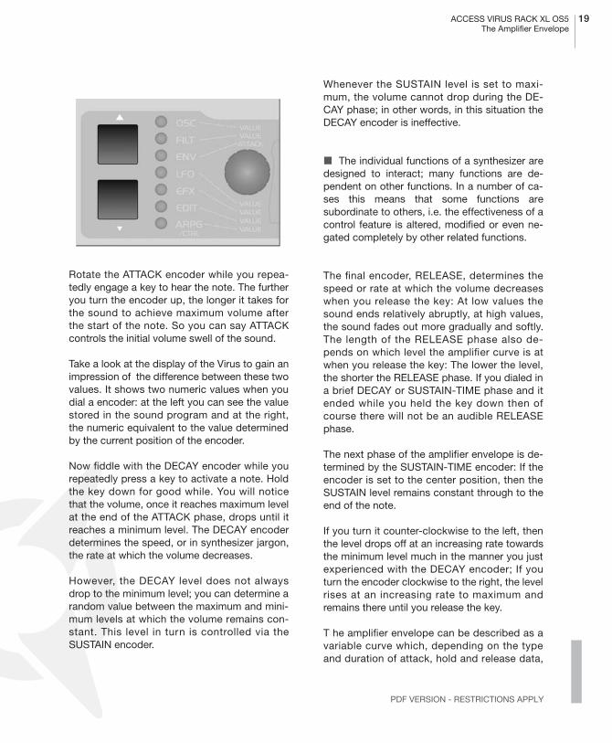
Locate the two vertically arrayed buttons nextto the seven LEDs. Use these UP and DOWNbuttons to select from among the seven para-meter groups and/or sections. The appropriateLED lights up to indicate that the given sectionhas been selected. Select the ENV section. Thelabels on the five encoder knobs for this sectionread ATTACK, DECAY, SUSTAIN, SUS TIME andRELEASE.
These controls will help you to dial in volumecharacteristics called an amplifier envelope andput an end to the nerve-racking drone that mayremind you of one of those cheesy organs thatyou hear in ‘60s B-movie sound tracks.
The section labeled ENV addresses the enve-lope. On a synthesizer, an envelope is used tomodulate sound over time. The Virus has twoenvelopes, one for volume (AMP ENV) and onefor the filters (FILT ENV), which we will learn mo-re about later. The five encoder knobs serve toshape either the amplifier envelope or the filterenvelope. Make sure that you can see AMPENV in the display, and not FILT ENV. If this isnot the case, use the PARAMETER buttons toset the section to the amplifier envelope.
ACCESS VIRUS RACK XL OS5
19
The Amplifier Envelope
PDF VERSION - RESTRICTIONS APPLY
Rotate the ATTACK encoder while you repea-tedly engage a key to hear the note. The furtheryou turn the encoder up, the longer it takes forthe sound to achieve maximum volume afterthe start of the note. So you can say ATTACKcontrols the initial volume swell of the sound.
Take a look at the display of the Virus to gain animpression of the difference between these twovalues. It shows two numeric values when youdial a encoder: at the left you can see the valuestored in the sound program and at the right,the numeric equivalent to the value determinedby the current position of the encoder.
Now fiddle with the DECAY encoder while yourepeatedly press a key to activate a note. Holdthe key down for good while. You will noticethat the volume, once it reaches maximum levelat the end of the ATTACK phase, drops until itreaches a minimum level. The DECAY encoderdetermines the speed, or in synthesizer jargon,the rate at which the volume decreases.
However, the DECAY level does not alwaysdrop to the minimum level; you can determine arandom value between the maximum and mini-mum levels at which the volume remains con-stant. This level in turn is controlled via theSUSTAIN encoder.
Whenever the SUSTAIN level is set to maxi-mum, the volume cannot drop during the DE-CAY phase; in other words, in this situation theDECAY encoder is ineffective.
�
The individual functions of a synthesizer aredesigned to interact; many functions are de-pendent on other functions. In a number of ca-ses this means that some functions aresubordinate to others, i.e. the effectiveness of acontrol feature is altered, modified or even ne-gated completely by other related functions.
The final encoder, RELEASE, determines thespeed or rate at which the volume decreaseswhen you release the key: At low values thesound ends relatively abruptly, at high values,the sound fades out more gradually and softly.The length of the RELEASE phase also de-pends on which level the amplifier curve is atwhen you release the key: The lower the level,the shorter the RELEASE phase. If you dialed ina brief DECAY or SUSTAIN-TIME phase and itended while you held the key down then ofcourse there will not be an audible RELEASEphase.
The next phase of the amplifier envelope is de-termined by the SUSTAIN-TIME encoder: If theencoder is set to the center position, then theSUSTAIN level remains constant through to theend of the note.
If you turn it counter-clockwise to the left, thenthe level drops off at an increasing rate towardsthe minimum level much in the manner you justexperienced with the DECAY encoder; If youturn the encoder clockwise to the right, the levelrises at an increasing rate to maximum andremains there until you release the key.
T he amplifier envelope can be described as avariable curve which, depending on the typeand duration of attack, hold and release data,
20
CHAPTER 5
Introduction
automatically influences an imaginary volumeencoder (turns it up or down). At the beginningof the note, ATTACK controls the rise or rate ofincrease to the maximum level. Once the maxi-mum level is achieved, DECAY determines thefall or rate of decrease to the SUSTAIN value,which is infinitely variable between the mini-mum and maximum levels. The amplifier enve-lope may remain at this value until the end ofthe note, fall towards the minimum level as de-termined by the variable TIME value, or even ri-se again towards the maximum level. After theend of the note, RELEASE controls the fall or
rate of decrease to the minimum level. Conse-quently, the control encoders labeled ATTACK,DECAY, TIME and RELEASE control a speed orrate, where as SUSTAIN actually controls a le-vel.
�
THE FIRST FILTER
Now we will take a look at a component of asynthesizer that is generally regarded as themost important functional unit as it enables dra-stic sound shaping measures: the filter - or inthe case of the Virus, the two filters.
But first we will concentrate on just one of thetwo filters.
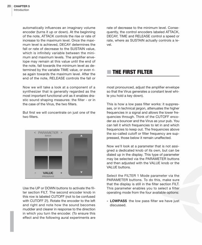
Use the UP or DOWN buttons to activate the fil-ter section FILT. The second encoder knob inthis row is labeled CUTOFF (not to be confusedwith CUTOFF 2!). Rotate the encoder to the leftand right and note how the sound becomesmuddier and clearer in response to the directionin which you turn the encoder. (To ensure thiseffect and the following aural experiments are
most pronounced, adjust the amplifier envelopeso that the Virus generates a constant level whi-le you hold a key down).
This is how a low pass filter works: it suppres-ses, or in technical jargon, attenuates the higherfrequencies in a signal and allows the lower fre-quencies through. Think of the CUTOFF enco-der as a bouncer and the Virus as your pub. Youcan tell it which frequencies to let in and whichfrequencies to keep out. The frequencies abovethe so-called cutoff or filter frequency are sup-pressed, those below it remain unaffected.
Now we'll look at a parameter that is not assi-gned a dedicated knob of its own, but can bedialed up in the display. This type of parametermay be selected via the PARAMETER buttonsand then adjusted with the VALUE knob or theVALUE buttons.
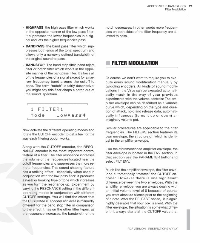
Select the FILTER 1 Mode parameter via thePARAMETER buttons. To do this, make surethat the display is still in the filter section FILT.This parameter enables you to select a filteroperating mode from the four available options:
- LOWPASS
the low pass filter we have justdiscussed.
ACCESS VIRUS RACK XL OS5
21
Filter Modulation
PDF VERSION - RESTRICTIONS APPLY
- HIGHPASS
the high pass filter which worksin the opposite manner of the low pass filter:It suppresses the lower frequencies in a sig-nal and lets the higher frequencies pass.
- BANDPASS
the band pass filter which sup-presses both ends of the tonal spectrum andallows only a narrowly defined bandwidth ofthe original sound to pass.
- BANDSTOP
The band stop filter, band rejectfilter or notch filter which works in the oppo-site manner of the bandpass filter. It allows allof the frequencies of a signal except for a nar-row frequency band around the cutoff topass. The term “notch” is fairly descriptive;you might say this filter chops a notch out ofthe sound spectrum.
01111111111111111112
1 FILTER1 Mode Lowpass≤61111111111111111154
Now activate the different operating modes androtate the CUTOFF encoder to get a feel for theway each filtering option works.
Along with the CUTOFF encoder, the RESO-NANCE encoder is the most important controlfeature of a filter. The filter resonance increasesthe volume of the frequencies located near thecutoff frequencies and suppresses the more re-mote frequencies. This sound shaping featurehas a striking effect - especially when used inconjunction with the low pass filter: it producesa nasal or honking type of tone which increasesas you turn the resonance up. Experiment byvarying the RESONANCE setting in the differentoperating modes in conjunction with differentCUTOFF settings. You will find the effect thatthe RESONANCE encoder achieves is markedlydifferent for the band stop filter in comparisonto the effect it has on the other filter types: asthe resonance increases, the bandwidth of the
notch decreases; in other words more frequen-cies on both sides of the filter frequency are al-lowed to pass.
�
FILTER MODULATION
Of course we don’t want to require you to exe-cute every sound modification manually bytwiddling encoders. All kinds of sound modifi-cations in the Virus can be executed automati-ca l ly much in the way of your prev iousexperiments with the volume controls: The am-plifier envelope can be described as a variablecurve which, depending on the type and dura-tion of attack, hold and release data, automati-cal ly influences (turns i t up or down) animaginary volume pot.
Similar procedures are applicable to the filterfrequencies. The FILTERS section features itsown envelope, the structure of which is identi-cal to the amplifier envelope.
Like the aforementioned amplifier envelope, thefilter envelope is located in the ENV section. Inthat section use the PARAMETER buttons toselect FILT ENV.
Much like the amplifier envelope, the filter enve-lope automatically “rotates” the CUTOFF en-coder. However there is one s ignificantdifference between the two envelopes. With theamplifier envelope, you are always dealing withan initial volume level of 0 because of courseyou want absolute silence prior to the beginningof a note. After the RELEASE phase, it is againhighly desirable that your box is silent. With thefilter envelope, the situation is somewhat differ-ent: It always starts at the CUTOFF value that

22
CHAPTER 5
Introduction
you determined manually. And it is definitelynot always desirable that the filter frequency isbrought to the maximum level.
Consequently, you need a tool that limits the ef-fective range of the fi lter. This is why weequipped the Virus with a control labeled ENVAMOUNT (short for Envelope Amount). This en-coder is positoned in the Filter section. Whenthe encoder is turned counter-clockwise to thefar left, the filter has no effect on the cutoff fre-quency; the further you turn the encoder to theright, the greater the effect the filter envelopehas on the filter frequency. The maximum levelof the envelope may lie outside the audiblerange when the filter has already been partiallyopened via the CUTOFF encoder or was manip-ulated via other control options. In extreme cas-es where the filter is already completely open,the filter frequency cannot be increased regard-less of how high you set the ENV AMOUNT.
Go ahead and spend some experimenting withdifferent ENV AMOUNT, CUTOFF and RESO-NANCE settings for the diverse filter operatingmodes. Also try varying the settings for the am-plifier envelope. You will find that with just thesefew parameters you are able to come up with avast amount of sound settings. If you areamong the many musicians who are associativelisteners, you might say many of the settingsproduce sounds reminiscent of stringed-instru-ments; some sound picked, p lucked orsnapped, others sound bowed.
For your next experiment set the amplifier enve-lope so that you hear a constant level when youpress and hold a note. Now deactivate the filterenvelope by setting the ENV AMOUNT to 0. SetFilter-1Filter-1 to low pass mode and decreasethe filter frequency until you just barely hear amuddy signal when you play notes in the mid-range.
Now play a few higher and lower notes. You willfind that the lower notes have a greater over-tone content, whereas the higher notes soundmuddier and their volume decreases until thenotes are completely inaudible. You might al-ready suspect what this is all about: As thenotes are transposed ever lower, more portionsof the signal fall below the cutoff frequency,whereas with the notes that are transposed ev-er higher, more portions of the signal rise abovethe cutoff frequency and subsequently are sup-pressed until the root note and the last audibleportion of the signal is silenced.
To avoid this effect - or if desirable, to amplify it- you have the option of influencing the cutofffrequency via the pitch of the note, i.e. the notenumber. The degree of influence is determinedby the KEY FOLLOW parameter. You'll find thisparameter in the filter section using the PA-RAMETER buttons just like you did in FILTER 1mode earlier on.
Please note that KEY FOLLOW is a so-calledbipolar parameter: Its control range is not limit-ed to the positive end of the spectrum (0 to amaximum of 127). Bipolar controls effect nega-tive values as well, in this case from the nega-tive maximum of -64 through 0 an on to thepositive maximum of +63. Consequently, if thisvalue is set to the center position (0) the pitch ofthe notes corresponding to the keys on yourkeyboard has no effect on the cutoff frequency.If on the other hand you turn the KEY FOLLOWparameter clockwise towards the positive con-trol range, you will find that the filter opens upincreasingly as the pitch increases with highernotes. At lower notes, the filter closes downagain. If you turn the encoder counter-clock-wise towards the negative control range, theKEY FOLLOW effect is reversed. With the Virus,you will encounter this feature - intensity controlvia a bipolar parameter - again in conjunctionwith other modulation sources and targets.

ACCESS VIRUS RACK XL OS5
23
The Saturation Stage
PDF VERSION - RESTRICTIONS APPLY
Now experiment as much as you like with differ-ent KEY FOLLOW settings and tune the set-tings via the CUTOFF encoder. And rememberto bring all of the other parameters you haveencountered thus far into play.
�
THE SATURATION STAGE
In the signal chain of the Virus, Filter-1 is fol-lowed by a saturation stage. It enables you toadd overtones to the filtered signal via distor-tion. Locate the parameter SATURATION in theFILTERS section.
01111111111111111112
1 SATURATION Curve Off≤ 61111111111111111154
The display will read ”SATURATION CURVEOFF”, which means exactly what it says. Withthe VALUE buttons or the VALUE encoder, youcan now select from a number of saturation/dis-tortion curves.
At this point we would like to mention the OSCVOL parameter, which is next to the SATURA-TION parameter. The portion of the controlrange from the far left to the center position (0)determines the volume of the filter section’s in-put signal. The portion of the control range lo-cated to the right of the center position doesnot achieve any increase in volume; it simplyintensifies the degree of saturation or distortion.This effect is only achieved when you have acti-vated a saturation curve.
Feel free to experiment with the diverse satura-tion curves and be sure to vary the OSC VOLsettings. Note how the different CUTOFF andRESONANCE settings influence the saturationcurve.
� THE SECOND FILTER
You probably noticed that by a adding a bit ofsaturation to the signal you can come up with apretty heavy, aggressive sound - especially witha low filter frequency level and high resonance.You’re probably thinking these types of soundscould do with some more filtering. We had thesame idea, which is one of the reasons why weequipped the Virus with another filter per voice.
The technical design of this second filter isidentical to the first, so we won’t discuss it inas much detail as we did the first filter. Howev-er, there are few differences in how you handlethe second filter:
A Only two parameters of the Virus are allocat-ed exclusively to Filter-2: CUTOFF 2 and FILT 2MODE.
A The RESONANCE, ENV AMOUNT and KEYFOLLOW parameters can be allocated to eitherof the two filters or both simultaneously. Usethe FILTER SELECT menu in the FILTERS sec-tion to select the desired operating mode. Forinstance, if you choose FILT2, then the valuesyou set with RESONANCE, ENV AMOUNT andKEY FOLLOW apply exclusively to Filter-2. Thecorresponding parameters of Filter 1 remain un-affected. On the other hand, if you chooseFILT1+2, the values that you dial in apply by thesame measure to Filters 1 and 2.

24 CHAPTER 5Introduction
In the sound program we are using for our ex-periments, both filters are selected, so that alladjustments to the given parameters affectboth filters. However, you have yet to actuallyhear the effect of Filter-2 on the signal becauseit is mixed out of the audible signal path of theVirus.
Before we get started with our next experiment,deactivate SATURATION, set the ENV AMOUNTof the filter envelope to zero and set CUTOFF 2to the center position so that Filter-2 always hasthe same cutoff frequency as Filter-1 (we’ll ex-plain CUTOFF 2 a bit later). Set CUTOFF to amedium or middle value and turn the RESO-NANCE encoder counter-clockwise to the farleft to achieve a relatively muddy sound.
Now locate the FILTER BALANCE parameter inthe FILT menu and rotate it from the left to theright. You will note the sound becomes muddieras you turn the encoder towards the center po-sition and that the sound is somewhat brighterat the far right of the control range then at thefar left.
The reason for this effect is that when you turnthe FILTER BALANCE to the far left, only Filter-1 is audible. When you rotate the parameter tothe right, Filter-2 is blended in so that it followsFilter-1 in the signal chain. When you turn theFILTER BALANCE clockwise, Filter-1 is blendedout of the signal chain until at the far right posi-tion only Filter-2 is active and audible.
Each filter in the Virus normally features 2 poles.However in the FILTER ROUTING operatingmode SER 6, Filter-1 operates with 4 poles, sothe signal patched through Filter-1 (FILTERBALANCE to the far left) is trimmed more dras-tically than when it is routed through Filter-2(FILTER BALANCE to the far right). When youset the FILTER BALANCE to the center position(12 o’clock) - as we mentioned before - the twofilters are routed in series, which means they re-spond as if they were a single filter with 6 poles
and consequently a great deal of slope. This iswhy the input signal is trimmed substantiallywhen you set the parameter to this position.
Experiment with the diverse FILTER BALANCEvalues to get a feel for the different degrees ofslope. Rotate the CUTOFF encoder or activatethe filter envelope (for both filters!) to hear thefilters in action.
The CUTOFF 2 parameter is a special feature: Itcontrols the cutoff frequency of the second fil-ter, but is subordinate to the CUTOFF encoderlocated above it. In other words, at the centerposition (12 o’clock) the manually selected fre-quency of Filter-2 is identical to that of Filter-1.When you rotate the encoder to the left the cut-off frequency level of Filter-2 is increased rela-tively to Filter-1, when you turn to encoder tothe right the cutoff frequency level is decreasedrelatively. Now when you adjust the CUTOFF,you adjust the cutoff frequency of both filters bythe same measure! This feature lets you deter-mine a difference in values in the filter frequen-cies (called an offset) via the CUTOFF2 encoderwhich remains constant whenever you adjustthe CUTOFF encoder.
Yet another experiment in which you can comeup with new filtering characteristics that aretypical of the Virus:
Set FILTER BALANCE to the center position(12 o’clock) and CUTOFF 2 to the maximumlevel. The FILTER ROUTING operating modemust remain SER 6. Set CUTOFF and RESO-NANCE to a middle value and select a clearlyaudible SATURATION curve.
Now you can filter this complex signal pro-duced by a combination of the saturation stageand the Filter-1 yet again. Rotate the CUTOFF 2encoder slowly towards the center position (12o’clock). You can hear how Filter-2 graduallymodifies the distorted signal. You can set aRESONANCE value for Filter-2 if you choose

ACCESS VIRUS RACK XL OS5 25Filter Routing
PDF VERSION - RESTRICTIONS APPLY
FILT 2 in the FILTERS SELECT menu and rotatethe RESONANCE encoder to the desired posi-tion. Set the CUTOFF 2 encoder to a position tothe right of the center position. This configura-tion can be described as a complex non-linearfilter set up where the cutoff frequency is con-trolled via the CUTOFF encoder. You can dial ina wide range of sound-shaping option via CUT-OFF 2. Also try modifying the resonances ofboth filters as well as the SATURATION curve tocome up with different filtering characteristics.
Now experiment with the diverse filter modesand listen closely to the effect of the parame-ters RESONANCE, ENV AMOUNT and KEYFOLLOW in conjunction with FILTERS SELECT.Please also keep in mind that the chances ofchoking a sound off are substantially greaterwhen you are using both filters: For instance, ifthe first filter is used as a low pass with a lowcutoff frequency and the second as a high passwith a high cutoff frequency, the Virus will notgenerate an audible signal when you set FIL-TER BALANCE to the center position (12o’clock).
� FILTER ROUTING
The final parameter we’ll discuss for the timebeing is FILTER ROUTING. This feature offersseveral filter routing options which allow you tooperate the filters in series, i.e. patch one afterthe other in the signal chain, or in parallel, whichmeans side by side in the signal chain:
- SER-4 The filters are switched in series; withtwo poles each (12dB/Okt.), both filters havethe same slope for a total of four filter poles(24dB/Okt.).
- SER-6 The filters are switched in series; Fil-ter-1 has four poles (24dB/Okt.), Filter-2 hastwo poles (12dB/Okt.) so the overall slope isequivalent to six poles (36dB/Okt.).
- PAR-4 The filters are switched in parallel andfeature two poles each (12dB/Okt.).
- SPLIT The filters are switched in parallel andfeature two poles each (12dB/Okt.). Additional-ly, they receive independent input signals (moreon this later). Each of the two oscillators routesits signal into one of the two filters whose sig-nals can be spread in the panorama via a pa-rameter called UNISON Pan Spread.
� Regardless of which FILTER ROUTING op-tion you chose, the SATURATION stage is al-ways post-Filter-1, i.e. after Filter in the signalchain.

26 CHAPTER 5Introduction
Her is the filter routings capabilities of the Virus.

ACCESS VIRUS RACK XL OS5 27The First Oscillator
PDF VERSION - RESTRICTIONS APPLY
� THE FIRST OSCILLATOR
To this point, we have turned our attention ex-clusively to sound-shaping functions and havealways started with the same basic material: aso-called sawtooth wave. This waveshape isespecially well-suited as a neutral starting pointas it contains all of the so-called natural scale ofovertones, which give the filter plenty of qualitymaterial to work with.
The filters, with the exception of a notch filter orband stop (BS), trim the far reaches of the tonalspectrum, so for instance a signal sounds mud-dier after it has been routed through a low passfilter. You can well imagine that this type ofsound modification is substantial but insuf-ficient for shaping more subtle differences in to-ne. For instance the tone of a trumpet differssignificantly from that of a saxophone eventhough no one would seriously claim that eitherof the instruments has a muddier tone than theother.
What you need is a sound-shaping option forthe portion of a signal that a filter allows topass. And of course you also need a tool for de-termining the pitch of a signal. In synthesizers,both of these tasks are executed by oscillators.They oscillate at a variable pitch that can bemodulated and they also generate different wa-veshapes which give the filters a wider varietyof material to work with.
The Virus is equipped with two main oscillatorsand a so-called suboscillator. We will first take alook at Oscillator 1, which is the oscillator youhave already heard in action during your experi-ments thus far.
Dial in the same basic sound that you startedwith at the very beginning (A127 - START -). Tothis end, first press the SINGLE button in order
to return to Play mode from the selected para-meter section. In Play mode, you can switchsounds via the VALUE buttons.
Now modify the amplifier envelope so you areworking with a less grating sound, but holdback on any other filter or saturation modificati-ons so you can hear the purest oscillator signalpossible.
Locate the section labeled “1”, it is bordered offin a separate area at the far left of the sectionlabeled OSCILLATORS. No check out the twoencoders labeled SHAPE and WAVE SEL/PW.These enable you determine the waveshapeand consequently the tonal spectrum of Oscilla-tor 1.
In the sound program, SHAPE is preset to thecenter position. The display shows “Saw” forthe sawtooth waveform.
Press and hold a key and slowly turn the enco-der clockwise. You should be able to hear howthe tone becomes increasingly more hollow-so-unding. You might say this effect thins thesound out, but in any case, the entire tonalspectrum is affected by an equal measure,which is an audio result filters are unable toachieve.
The waveshape that is audible when you turnthe SHAPE encoder to the far right is a so-cal-led pulse wave. It is unique because the durati-on of the negative pulse is equal to the durationof the positive pulse: It has a so-called pulsewidth of 50%. The tone of a pulse wave is diffe-rent to that of a sawtooth wave because it doesnot contain all overtones in the natural overtonescale, only the odd-numbered tones, i.e. thefirst (the root note that determines the pitch),third, fifth, and so forth. By turning the SHAPE
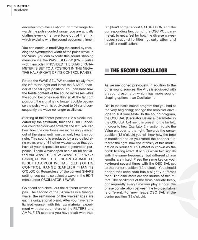
28 CHAPTER 5Introduction
encoder from the sawtooth control range to-wards the pulse control range, you are actuallydialing every other overtone out of the mix,which explains why the sound becomes thinner.
You can continue modifying the sound by redu-cing the symmetrical width of the pulse wave. Inthe Virus, you can execute this sound-shapingmeasure via the WAVE SEL/PW (PW = pulsewidth) encoder, PROVIDED THE SHAPE PARA-METER IS SET TO A POSITION IN THE NEGA-TIVE HALF (RIGHT) OF ITS CONTROL RANGE.
Rotate the WAVE SEL/PW encoder slowly fromthe left to the right and leave the SHAPE enco-der at the far right position. You can hear howthe treble content of the sound increases whilethe sound becomes ever thinner. At the far rightposition, the signal is no longer audible becau-se the pulse width is equivalent to 0% and con-sequently the wave no longer oscillates.
Starting at the center position (12 o’clock) indi-cated by the sawtooth, turn the SHAPE enco-der counter-clockwise towards the left. You canhear how the overtones are increasingly mixedout of the signal until you can only hear the rootnote. This sound is produced by a so-called si-ne wave, one of 64 other waveshapes that youhave at your disposal for sound generation pur-poses. These waveshapes can also be activa-ted via WAVE SEL/PW (WAVE SEL: WaveSelect), PROVIDED THE SHAPE PARAMETERIS SET TO A POSITIVE HALF (LEFT) OF ITSCONTROL RANGE (EARLIER THAN 12O’CLOCK). Regardless of the current SHAPEsetting, you can also select a wave in the EDITmenu under OSCILLATOR 1 WAVE.
Go ahead and check out the different wavesha-pes. The second of the 64 waves is a trianglewave, the remainder of the waveshapes areeach a unique tonal blend. After you have fami-liarized yourself with this raw material, experi-ment with the parameters of the FILTERS andAMPLIFIER sections you have dealt with thus
far (don’t forget about SATURATION and thecorresponding function of the OSC VOL para-meter), to get a feel for how the diverse waves-hapes respond to filtering, saturation andamplifier modifications.
� THE SECOND OSCILLATOR
As we mentioned previously, in addition to theother sound sources, the Virus is equipped witha second oscillator which has more sound-shaping options than Oscillator 1.
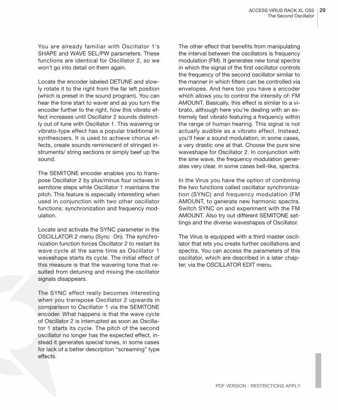
Dial in the basic sound program that you had atthe very beginning; change the amplifier enve-lope to suit your taste. In the sound program,the OSC BAL (Oscillator Balance) parameter inthe OSCILLATOR menu is preset to the far left.In order to hear Oscillator 2 in action, rotate theValue encoder to the right. Towards the centerposition (12 o’clock) you will hear how the toneis modified and as you rotate the encoder fur-ther to the right, how the intensity of this modifi-cation is reduced. This effect is known as thecomb filtering effect. It occurs when two signalswith the same frequency but different phaselengths are mixed. Press the same key on yourkeyboard several times with the OSC BAL setto the center position (12 o’clock). You shouldnotice that each note has a slightly differenttone. The oscillators are the source of this ef-fect. The oscillators of the Virus oscillate freely,consequently every time you play a note, thephase constellation between the two oscillatorsis different. For now, leave OSC BAL at thecenter position (12 o’clock).
ACCESS VIRUS RACK XL OS5 29The Second Oscillator
PDF VERSION - RESTRICTIONS APPLY
You are already familiar with Oscillator 1’sSHAPE and WAVE SEL/PW parameters. Thesefunctions are identical for Oscillator 2, so wewon’t go into detail on them again.
Locate the encoder labeled DETUNE and slow-ly rotate it to the right from the far left position(which is preset in the sound program). You canhear the tone start to waver and as you turn theencoder further to the right, how this vibrato ef-fect increases until Oscillator 2 sounds distinct-ly out of tune with Oscillator 1. This wavering orvibrato-type effect has a popular traditional insynthesizers. It is used to achieve chorus ef-fects, create sounds reminiscent of stringed in-struments/ string sections or simply beef up thesound.
The SEMITONE encoder enables you to trans-pose Oscillator 2 by plus/minus four octaves insemitone steps while Oscillator 1 maintains thepitch. This feature is especially interesting whenused in conjunction with two other oscillatorfunctions: synchronization and frequency mod-ulation.
Locate and activate the SYNC parameter in theOSCILLATOR 2 menu (Sync On). The synchro-nization function forces Oscillator 2 to restart itswave cycle at the same time as Oscillator 1waveshape starts its cycle. The initial effect ofthis measure is that the wavering tone that re-sulted from detuning and mixing the oscillatorsignals disappears.
The SYNC effect really becomes interestingwhen you transpose Oscillator 2 upwards incomparison to Oscillator 1 via the SEMITONEencoder. What happens is that the wave cycleof Oscillator 2 is interrupted as soon as Oscilla-tor 1 starts its cycle. The pitch of the secondoscillator no longer has the expected effect, in-stead it generates special tones, in some casesfor lack of a better description “screaming” typeeffects.
The other effect that benefits from manipulatingthe interval between the oscillators is frequencymodulation (FM). It generates new tonal spectrain which the signal of the first oscillator controlsthe frequency of the second oscillator similar tothe manner in which filters can be controlled viaenvelopes. And here too you have a encoderwhich allows you to control the intensity of: FMAMOUNT. Basically, this effect is similar to a vi-brato, although here you’re dealing with an ex-tremely fast vibrato featuring a frequency withinthe range of human hearing. This signal is notactually audible as a vibrato effect. Instead,you’ll hear a sound modulation, in some cases,a very drastic one at that. Choose the pure sinewaveshape for Oscillator 2. In conjunction withthe sine wave, the frequency modulation gener-ates very clear, in some cases bell-like, spectra.
In the Virus you have the option of combiningthe two functions called oscillator synchroniza-tion (SYNC) and frequency modulation (FMAMOUNT, to generate new harmonic spectra.Switch SYNC on and experiment with the FMAMOUNT. Also try out different SEMITONE set-tings and the diverse waveshapes of Oscillator.
The Virus is equipped with a third master oscil-lator that lets you create further oscillations andspectra. You can access the parameters of thisoscillator, which are described in a later chap-ter, via the OSCILLATOR EDIT menu.

30 CHAPTER 5Introduction
� THE MIXER SECTION
You have already come across two parametersof the MIXER section: OSC BAL determines themix ratio between Oscillators 1 and 2; in the lefthalf of its control range, OSC VOL determinesthe master volume of the oscillator mix. In theright half of the control range from the centerposition to the far right, OSC VOL increases thesaturation intensity when a SATURATION curvehas been activated.
Now we’ll take a closer look at the SUB OSCparameter: It controls the volume of the thirdoscillator, the so-called SubOscillator, which al-ways operates an octave below Oscillator 1.
The SubOscillator is mixed to the Oscillator 1and 2 master mix signal as determined by theOSC BAL parameter. The master volume of thecomposite mix is controlled by the OSC VOLparameter. The only other parameter availablefor the SubOscillator is accessible via the OS-CILLATOR EDIT menu where you have the op-tion of selecting a triangle or pulse waveshape(SUB OSCILLATOR WAVE SQUARE/TRIAN-GLE).
Another voice-internal signal source of the Virusis the Noise Generator (NOISE Volume). Pleasekeep in mind that the level of the Noise Genera-tor is not subject to the master volume control-led by the OSC VOL parameter. In other words,it is audible even when OSC VOL is set to zero.
The VIRUS’ ring modulator is a new soundsource. The output of the two oscillators is mul-tiplied to create interesting sounds with rich en-
harmonic overtones. These overtones are highlydependent on the frequency coherence of bothoscillators and it’s waveforms. The frequencycoherence can be changed, for instance usethe OSC2 SEMITONE parameter. To blend inthe ring modulator use EDIT: RINGMODULA-TOR VOLUME (in OSCILLATOR EDIT Menu). Ifthe RINGMODULATOR VOLUME is zero, thering modulator is switched off. OSC VOL doesnot affect the ring modulator level (or indeed thenoise volume). Therefore the original oscillatorsignal can be leveled independently of the ringmodulator. Be sure to check out what the ringmodulator does when you select a sine wavefor Oscillator 1 and 2.
Now we can go on and solve the mysteries ofthe signal flow as determined by the FILTERROUTING operating mode SPLIT: Here Oscilla-tor 1 and the SubOscillator are routed to Filter-1, whereas Oscillator 2 and the Noise Generatorare routed to Filter-2. Although the soundsources are split into two signal paths, you canstill control the volume levels of the different el-ements as well as OSC VOL in the usual man-ner.
� THE LFOS
When you first started this series of experi-ments with sounds, we promised that many ofthe functions the Virus can be “programmed”so that they are executed automatically. Youhave already learned how to control the volume
and cutoff frequencies of both filters as well asthe pitch and intensity of the frequency modula-tion of Oscillator 2 via “preprogrammed” enve-lopes. These options are great, but you havealready encountered a number of functions
ACCESS VIRUS RACK XL OS5 31The LFOs
PDF VERSION - RESTRICTIONS APPLY
where it would be a helpful if you could alsoprogram them to be executed automatically.And of course envelopes are great modulationsources, but you have to play a note every timeyou want to initiate an envelope. During yourexperiments you probably came across a func-tion or two you would like to be able to controlperiodically - independently of notes. Somefeatures that come to mind are traditional tech-niques such as vibrato (periodic pitch control)and tremolo (periodic volume control). Anotheroption you might like to have at your disposal israndom parameter control.
In the Virus, both of these tasks are executedby a so-called LFO (low frequency oscillator)that oscillates at frequencies below the audiblerange. An LFO is similar to the oscillators youhave encountered thus far, but it oscillates sig-nificantly slower so that its output signal is toolow for human hearing. So what good are they ifyou can’t hear them? LFOs are used in muchthe same manner as envelopes, with the majordifference that the are repeated indefinitely.
LFO 1Start with the usual basic sound configurationor chose a modified sound to suit your taste.Locate the RATE encoder in the LFO 1 sectionof the control panel. The VIRUS is equippedwith an LED that indicates the speed of the LFOas well as its waveshape. Turn the RATE encod-er and check out how the flash of the LED indi-cates the change of pace as you rotate theencoder.
Currently you are unable to hear the effect ofthe LFO as its modulation intensity is set to 0 inthe sound program. In order to change this set-ting, you must access the five parameterscalled LFO AMOUNT button which works withthe modulation destinations Oscil lator1 ,Oscillator2, PulseWidth1+2, Resonance1+2 undFilterGain:
THE MODULATION TARGETS
- OSCILLATOR1 refers to the frequency ofoscillator 1
- OSCILLATOR2 refers to the frequency ofoscillator 2
- PULSEWIDTH1+2 means that the pulsewidths of both oscillators are controlled inunison
- RESONANCE1+2 refers to the resonancesof both filters. Please keep in mind that al-though each set of these parameters is as-signed a common modulation intensity, youcan still dial in different sound-shaping set-tings manually. In other words, the audible re-sult of a joint modulation varies according tothe values you have determined for the otherparameters.
- FILTERGAIN This term refers to the inputlevel of the first filter (and of course the sub-sequent saturation level) - although WITH-OUT THE LEVEL COMPENSATIONCONTROLLED VIA OSC VOL. Here you canactually modulate a parameter that is notmanually accessible. The effect of a FiltGainmodulation is a periodic change in the satura-tion level which is linked to a correspondingtremolo (periodic change in volume). If thesignal is not saturated in any manner, then theonly audible result is a tremolo effect.
Modulate the five parameters separately and incombinations with different intensities. Try toanticipate the sound you will come up withwhen you modulate the first oscillator, the sec-ond oscillator or both oscillators at once andsee if the results match your expectations. Ifyou can fairly reliably predict the outcome ofyour sound-shaping efforts, you should have ahandle on the information discussed thus farand can use your knowledge to create specificsounds you have in mind.
32 CHAPTER 5Introduction
During the course of your experiments, it is en-tirely possible that you have generated modula-tions that have no effect whatsoever on thesound, for instance if you modulate the fre-quency of Oscillator 2 although it is dialed outof the oscillator mix. When you run into thistype of problem, check out the signal routing, ifany configurations conflict with each other andmemorize the situation, problem and solution. Ifyou make a habit out of this, you won’t panicwhen you run into similar situations; insteadyou’ll keep your cool, analyze the unexpectedsound and fix the mix.
You are currently using a triangle as the LFOwaveshape. You shouldn’t have any problemassociating the periodic up and down fluctua-tion of the target parameter with this wave-shape. Now activate the other avai lablewaveshapes for LFO 1 and try to picture the re-spective waveshape and associate it with theresults of the modulation.
The third waveshape is a descending sawtoothwave. You can convert it into to an ascendingsawtooth by simply dialing in the requisite neg-ative modulation intensities (AMOUNT).
- S&H (Sample and Hold) is a structured ran-dom modulation. Here random modulationvalues are generated. The value is held untilthe next beat impulse, then it abruptly jumpsto a new random value.
- S&G (Sample and Glide) is a continual ran-dom modulation. Here the random valuesglide seamlessly into one another, the rate ofwhich is determined by random modulation ofthe RATE value.
The following 62 waveshapes are identical tothe oscillator section’s digital waves. These canbe used to create interesting rhythmic effects.
Continued your experiments with different LFOwaveshapes. Note that after a while you nolonger consciously hear minimal modulation in-tensities - depending on the waveshape andmodulation target (e.g. S&G +1 on OSC 1 or 2).However they do pep up the sound of lend it acertain vitality. The key to many great soundsare these types of minimal modulations.
You may have gathered that the LFOs of the Vi-rus are polyphonic:If several notes are played simultaneously,these are controlled by dedicated LFOs, eachwith a slightly varied rate. This effect livens upthe sound of chords, especially when they aresustained. To enhance this effect, activate theLFO-1 KEY FOLLOW.
This function enables you to control the rate ofthe LFOs via the pitch, or more accurately, viathe MIDI note number, so that higher notes ge-nerate faster LFO rates. As result, when youpress and hold several notes you will hear allkinds of substantially different periodic fluctua-tions.
Finally, the LFOs can also be used as additionalenvelopes. The control feature for this effect isthe ENV MODE button. When you press thisbutton, two things occur: For one, the LFO nolonger initiates its cycles periodically, but onlyonce at and in sync with the start of a note, andfor the other, the active range of the LFO isswitched from bipolar (in both directions fromthe zero position) to unipolar (from zero in onedirection only). Please note that this applies tothe modulation target but not the modulation in-tensity. Here you can still determine a value inthe entire bipolar range.
This effect is especially prominent when used inconjunction with the sawtooth wave, which en-ables a fade-out type of effect (when you dial ina positive AMOUNT value) or a volume-swelltype of effect (negative AMOUNT) for the availa-ble modulation targets. Using the LFO Contour
ACCESS VIRUS RACK XL OS5 33Soft Knob 1/2
PDF VERSION - RESTRICTIONS APPLY
encoder in the LFO section, you can have the”ramp” rise or fall exponentially. If you choose atriangle for your waveshape, the device willgenerate an ascending phase (attack) and a de-scending phase (decay). LFO Contour also letsyou determine the temporal relationship be-tween attack and decay; in other words, theirrespective rates.. Dial in the desired speed viathe RATE encoder.
You can also use S&H and S&G in ENV MODEto come up with some attractive results: S&Hgenerates a single random value at the start ofa note (in this case, the RATE encoder has noeffect); S&G works in the same manner al-though in this case the RATE value is crucial. Itdetermines the amount of time it takes to glidefrom the previous to the new random value.
LFO 2The design of the second LFO is essentially thesame as the first, so we’ll spare you the repeti-tion of details SHAPE 1 and 2 are available as ajoint modulation target; the filter frequenciesand the Panorama position can be manipulatedindividually. You may also freely select a param-eter for your modulation destination.
� SOFT KNOB 1/2
These are the two freely assignable controls.The destination of these controls can be de-fined within the Edit menu (SOFT KNOB 1/2MODE). There are two parameters, one globaland one local i.e. applying only to the currentSINGLE program (which will override the globaldefinition if defined). SOFT KNOB 2 doubles asa value control, and therefore only works as a
SOFT KNOB when the Virus is in Play mode i.e.no Edit menu is selected. For each SOFTKNOB, you can choose a short description froma list in the menu, and this will be saved as partof the SINGLE program. In Play mode, this willappear in the display – to remind you of whateach SOFT KNOB does when you are playingyour Virus.
� VOLUME AND PANORAMA
You probably noticed that the many of thesound shaping options available in the Virus oc-casionally influence the volume level. For in-stance, an unfiltered sawtooth is naturallylouder than a highly filtered sawtooth becausewhenever you blend a part of the frequencyspectrum out of the mix, you are automaticallyreducing the overall volume of the signal. This iswhy the Virus is equipped with a programmablevolume parameter for each SINGLE PRO-GRAM. It enables you to balance out the vol-ume levels of your sound programs.
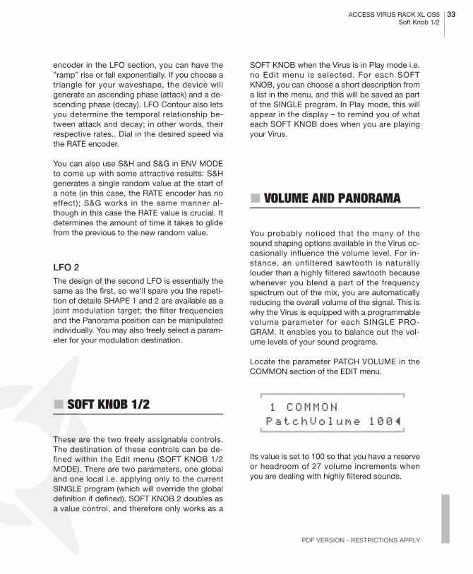
Locate the parameter PATCH VOLUME in theCOMMON section of the EDIT menu.
01111111111111111112
1 COMMON PatchVolume 100≤ 61111111111111111154
Its value is set to 100 so that you have a reserveor headroom of 27 volume increments whenyou are dealing with highly filtered sounds.

34 CHAPTER 5Introduction
You have already dealt with the Panorama posi-tion as a modulation target of LFO 2. Here youcan not only modulate it, but also determinesettings manually. For this purpose, use the pa-rameter PANORAMA which is also located inthe COMMON section of the EDIT menu. Likemany other parameters, Panorama is a startingpoint for modulations. For instance you canmodulate the Panorama position via LFO 2even if you have already set the Panorama tothe far left position. In this case of course youwill only hear the Panorama position shift to theright.
� VELOCITY
Velocity is one of the preferred modulationsources of keyboard players: A light key attackgenerates a low velocity value for the givennote, a heavy touch generates a high velocityvalue. In the Virus you have ten modulation tar-gets available for Velocity. Locate the VELOCI-TY section in the EDIT menu.
01111111111111111112
1 VELOCITY Osc1Shape +0≤61111111111111111154
There you will find the modulation intensitiesfor:
which you can manipulate independently of oneanother in the familiar bipolar control range.
A light key attack generates a low velocity valuefor the given note, a heavy touch generates ahigh velocity value.
� UNISON MODE
When we talked about the oscillators, we men-tioned that by subtly detuning signals, you canbeef up sounds and achieve string-like sounds.The Virus is equipped with features that allowyou to take this type of tonal manipulation astep further. On of these is the so-called UNI-SON MODE. It enables you to initiate two ormore voices for each note played, which in turnlets you detune many oscillators. UNISONMODE also offers the option of spreading thevoices generated by one note in the stereo pan-orama and shifting the phases of their LFOs sothat all types of periodic effects can be used toproduce an even more exciting signal.
OSC 1 SHAPE
OSC 2 SHAPE
PULSE WIDTH
FM AMOUNT
FILT 1 ENV AMT
FILT 2 ENV AMT
RESONANCE 1
RESONANCE 2
VOLUME
PANORAMA
ACCESS VIRUS RACK XL OS5 35The Effects
PDF VERSION - RESTRICTIONS APPLY
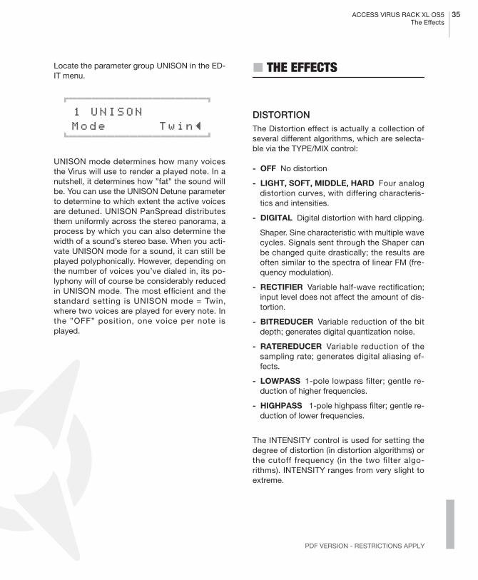
Locate the parameter group UNISON in the ED-IT menu.
01111111111111111112
1 UNISON Mode Twin≤ 61111111111111111154
UNISON mode determines how many voicesthe Virus will use to render a played note. In anutshell, it determines how ”fat” the sound willbe. You can use the UNISON Detune parameterto determine to which extent the active voicesare detuned. UNISON PanSpread distributesthem uniformly across the stereo panorama, aprocess by which you can also determine thewidth of a sound’s stereo base. When you acti-vate UNISON mode for a sound, it can still beplayed polyphonically. However, depending onthe number of voices you’ve dialed in, its po-lyphony will of course be considerably reducedin UNISON mode. The most efficient and thestandard setting is UNISON mode = Twin,where two voices are played for every note. Inthe ”OFF” position, one voice per note isplayed.
� THE EFFECTS
DISTORTIONThe Distortion effect is actually a collection ofseveral different algorithms, which are selecta-ble via the TYPE/MIX control:
- OFF No distortion
- LIGHT, SOFT, MIDDLE, HARD Four analogdistortion curves, with differing characteris-tics and intensities.
- DIGITAL Digital distortion with hard clipping.
Shaper. Sine characteristic with multiple wavecycles. Signals sent through the Shaper canbe changed quite drastically; the results areoften similar to the spectra of linear FM (fre-quency modulation).
- RECTIFIER Variable half-wave rectification;input level does not affect the amount of dis-tortion.
- BITREDUCER Variable reduction of the bitdepth; generates digital quantization noise.
- RATEREDUCER Variable reduction of thesampling rate; generates digital aliasing ef-fects.
- LOWPASS 1-pole lowpass filter; gentle re-duction of higher frequencies.
- HIGHPASS 1-pole highpass filter; gentle re-duction of lower frequencies.
The INTENSITY control is used for setting thedegree of distortion (in distortion algorithms) orthe cutoff frequency (in the two filter algo-rithms). INTENSITY ranges from very slight toextreme.
36 CHAPTER 5Introduction
PHASERThe Phaser effect produces resonant (or evencutting) emphasis on certain frequencies withinthe signal. The frequencies of these resonancesare shifted around the frequency spectrum,causing a distinctive movement in the sound.Tastefully applied, this effect is particularly goodfor pad sounds and for authentic traditionalelectric piano sounds.
The pure Phaser signal is the result of a fre-quency-dependent phase shift together with aslight pitch modulation from the phaser‘s ownLFO. Typical phaser sounds only appear whenthe processed signal is mixed with the dry sig-nal, usually at the same level. The TYPE/MIXcontrol is used to set this balance.
The INTENSITY control changes the level offeedback in the phased signal. Higher feedbacklevels cause higher resonant peaks in the sig-nal. The FEEDBACK parameter is bipolar, be-cause positive and negative feedback havedifferent characteristics.
More phaser parameters can be found in theEDIT menu: RATE and DEPTH control thespeed and intensity of modulation from thephaser‘s own LFO. The other three parametersaffect the general sound of the phaser: FRE-QUENCY determines the average frequency ofresonant peaks, STAGES is the number of reso-nant peaks and SPREAD is the distance be-tween resonant peaks within the frequencyspectrum.
THE CHORUS/FLANGER EFFECTAnother function that delivers great effectsbased on pitch fluctuation is the so-called cho-rus effect. Chorus actually consists of a briefdelay (generally up to approx. 50 ms) which isvaried periodically. By modulating the delay, thedelayed signal is slightly detuned to the input
signal (the so-called Doppler effect). This incon-sistency in pitch between the original and ef-fects signal is the source of the chorus effect.Feedback in the delay line enhances this effect.The left signal side is automatically modulatedin a different manner than the right, so a choruseffect is great for converting mono signals intostereo signals.
If the delay is less than approx. 10 milliseconds,than the effect is called flanging or a flanger ef-fect rather than chorus. In this case feedback iseven more significant because it generates res-onances that can be modulated and is thus yetanother source of radical sound effects. If youdetermine high feedback values, you can clear-ly hear how the two sides of the signal are mod-ulated differently - in reverse phase - by theLFO.
Locate the parameter group CHORUS in theEFFECTS menu.
01111111111111111112
1 CHORUS Dir/Eff OFF≤ 61111111111111111154
CHORUS DIR/EFF determines the balance be-tween the original signal and the processed sig-nal. The parameters RATE and SHAPE controlanother LFO that was installed specifically forthe chorus LFO. DELAY is used to set the delaytime, DEPTH determines the modulation inten-sity, and FEEDBACK controls the feedback lev-el. When you want to generate a flanger effect,the FEEDBACK parameter’s negative controlrange lets you dial in softer characteristics forthe flanger. Please keep in mind that the Chorussection in the Virus is fully stereophonic: Stereopositions as well as panorama modulations andstereo spread values that you have dialed inelsewhere remain intact in the effects signal.

ACCESS VIRUS RACK XL OS5 37The ArpeggiatorSoundDiver Virus
PDF VERSION - RESTRICTIONS APPLY
DELAY/REVERBThe DELAY/REVERB section is responsible fortwo different effects. The SEND control deter-mines the relative amount of effect signal:
The DELAY effect delays the input signal, and isusually used for echoes. The nominal delay timeset by the DELAY/REV-TIME control can bemodulated so that stereo phasing effects canappear. The delay time can be synchronized tothe clock so that echoes will be „in time“ andwill automatically adjust to any tempo changes.There are also several fixed-pattern delay algo-rithms, many of which delay the left and rightsides differently i.e. using different note values.Interesting rhythmic patterns can be created byincreading feedback level (via the FEEDBACK/DAMPING control).
REVERB simulates the effect of the boundariesin real spaces such as living rooms or cathe-drals. There are several parameters here whichgo beyond pure simulation of real spaces. Thepredelay parameter normally found in reverbunits is handled by the DELAY section de-scribed above – DELAY is in front of REVERB inthe signal path. REVERB can be synchronizedto the clock so you can seamlessly integrate theeffect into the rhythmic context of your music.The DELAY/REV TIME control determines thedecay time, and FEEDBACK/DAMPING sets theamount of high frequency damping.
01111111111111111112
1 DELAY EffectSend 0≤ 61111111111111111154
� THE ARPEGGIATOR
The ARP section located inconspicuously be-low the main volume control is the Virus ar-peggiator. This section only has an ON/OFFbutton and an EDIT button (which opens the ar-peggiator menu).
Arpeggiators break chords into individual notes,which are (usually) played back in succession.However, the Virus arpeggiator offers numerousplayback options including rhythmic repetitionof the unchanged chord. It is a very intuitive aidfor creating original rhythms, melodic sequenc-es, bass lines and much more. Simply switchon the Arpeggiator and try it out! The arpeggia-tor parameters are explained in the Parameterschapter.
� SOUNDDIVER VIRUS
Every Virus which leaves the factory includes acustom version of the software Emagic Sound-Diver. This is a powerful tool for managingsounds and controlling all Virus parametersfrom the computer (Mac or PC). Even if you pre-fer to control your Virus with its own knobs andbuttons most of the time, SoundDiver still hasquite a few useful functions and features whichcomplement the Virus user interface very well.
Take for instance SoundDiver’s Memory Man-ager. This can display the entire memory con-tents of the Virus clearly arranged on a singlepage, and has many comfortable functions tohelp you manage all your Single and Multi pro-grams. For instance SoundDiver lets you dragand drop sounds from one place to another, or

38 CHAPTER 5Introduction
rename them etc. etc. These are the kinds ofjobs which are handled much more comfortablyon a computer screen than in the (naturallysmaller) Virus menus.
SoundDiver’s library functions let you build upsound libraries of any size for the Virus, andstore these on your computer’s hard disk. Youcan sort some or all the sounds in a library ac-cording to several criteria, you can search forsounds, audition them and send several librarysounds at the same time to the Virus (via dragand drop) etc. etc. It is even possible to connectseveral Virii to SoundDiver and feed them withsounds from a single, central library. Selectivelyswapping sounds between two Virii could hard-ly be more comfortable.
Double-clicking on a sound in SoundDiver’sMemory Manager loads the sound into an edit-able graphic display of all parameters and val-ues. Although there is nothing in this editor youcannot do on the Virus itself, the attractive on-screen graphics give you an instant and com-plete overview of all parameters and their val-ues, so this is a practical alternative to the Virususer interface – especially when your unit is notvery accessible (e.g. when built into a 19” rack).
SoundDiver communicates via MIDI with the Vi-rus and requires two-way connections i.e. boththe MIDI INs and OUTs must be connected be-tween the Virus and the computer running thesoftware. SoundDiver has an integrated Helpsystem, which includes extensive informationabout the program itself as well as about the Vi-rus parameters.
For further information about the full version ofSoundDiver, as well as any questions you mayhave about the program, please contact Emag-ic (www.emagic.de).
� MORE TO COME
We have come to the end of these detailed in-structions for novices. We hope we were able tohelp you become a bit more familiar with yournew synthesizer and gain some confidence inhow to handle it. As we mentioned earlier, this isjust an introduction and does not cover all thefunctions and features of the Virus, only the ba-sic components and how they affect the soundof the Virus. You should now be able to come toterms with the in-depth look at the Virus in thefollowing section.

Concept and Operation

40 CHAPTER 6Concept and Operation
� OPERATING MODES
In the Virus you can select from two basic oper-at ing modes, SINGLE MODE and MULTIMODE.
In SINGLE MODE, the Virus is able to generatea single sound program only. All 32 voices, alleffects and all control features (with the excep-tion of the MULTI button) function in conjunc-tion with this one sound program. You mightsay a SINGLE program is a combination of allfunctions and effects that determine the soundof the Virus. In other words: A SINGLE programis a ”sound” of the Virus, that can be stored andrecalled.
The Virus provides access to 1024 SINGLEsounds. Next to the 256 RAM sounds (Bank Aand Bank B), you have six banks available witha total of 768 factory sounds. These banks, C toH, are stored in the FLASH ROM and can not beoverwritten via STORE.
The MIDI receive channel in SINGLE MODE isthe Global Channel. You can change the GlobalChannel in the CTRL menu.
In MULTI MODE, the Virus can combine up tosixteen (SINGLE) sound programs, amongwhich the maximum available number of 32voices are allocated dynamically. All simultane-ously available sounds can be manipulated inreal-time; for this purpose the control panel en-ables you to switch among the sixteen so-called PARTS.
In MULTI MODE, the actual sound parametersare augmented with other functions that dealwith how the involved SINGLE programs arestructured or organized. These include the vol-ume levels of the single programs, their MIDIchannels, output assignments, etc.
THE MULTI-SINGLE MODEWhile being in MULTI Mode, you’re unable tochange the SINGLE programs directly, whichwould admittedly be a handy option whenyou’re working with a sequencer. This is whythe Virus features MULTI SINGLE mode, which,strictly speaking, is more an alternative view ofMULTI mode rather than a further mode in itsown right.
Activate MULTI SINGLE mode by pressing theMULTI and SINGLE buttons simultaneously.The name of the selected MULTI program willdisappear and instead you’ll see the name ofthe SINGLE program for the selected PART.Now you can page or scroll through the 16PARTs using the PART buttons and select aSINGLE program for every channel. You canprocess the currently selected PART or, moreaccurately, edit its sound, using the control fea-tures. The menus let you access the usual SIN-GLE parameters. You’ll always see the numberof the selected PART on the upper left in thedisplay. The PART buttons don’t actuallychange sounds, they simply set the user inter-face of the Virus to the desired PART. Irrespec-tive of the given setting, all PARTs can becontrolled simultaneously via MIDI. Conse-quently, MULTI SINGLE mode, which makes

ACCESS VIRUS RACK XL OS5 41Operating Modes
PDF VERSION - RESTRICTIONS APPLY
handling so much easier, is the ideal choicewhen you’re working with a connected se-quencer.
Please bear in mind that MULTI SINGLE modeis really just another view of the normal MULTImode. MULTI SINGLE mode doesn’t offer aunique data type for storing sounds, it alwaysworks with the MULTI program currently select-ed in normal MULTI mode. All of the normalMULTI mode parameters (keyboard zones, etc.)remain intact and in force even though youcan’t view or vary them in MULTI SINGLEmode. You can set the device to normal MULTImode at any time by pressing the MULTI but-ton. To return to the MULTI SINGLE mode view,simply press the MULTI and SINGLE buttons si-multaneously.
When you’re working with a sequencer, startwith a MULTI program that features neutral set-tings for its ”administrative” parameters, for ex-ample, the MULTI program M0 Sequencer. Herethe PART numbers are identical to the MIDIchannels of the PARTs. Now when you work inMULTI SINGLE mode, the Virus responds as if itwere in SINGLE mode, except that you have 16sounds available simultaneously on 16 MIDIchannels. Use the PART buttons to select thesesounds.
You only need to exit MULTI SINGLE modewhen you want to store the MULTI program, forexample, to save the current global delay/re-verb setting. In MULTI mode, these settings arenot stored along with SINGLE sounds.
In addition, you can activate another completeMULTI program in MULTI mode only.
The MULTI mode parameters feature a dedicat-ed menu called the Multi Edit menu. Access itby pressing the Multi button while the device isin MULTI mode. The LED located over the MUL-TI button will light up to indicate that the MultiEdit menu is active. Press the MULTI buttonagain to return to normal Play mode. If the de-vice is in MULTI-SINGLE mode, press the MUL-TI and SINGLE buttons simultaneously toaccess the Multi Edit menu. It suffices to presseither the MULTI or SINGLE button to return tonormal Play mode from MULTI-SINGLE mode.
42 CHAPTER 6Concept and Operation
THE EDIT BUFFERSWhenever you play or edit a SINGLE program,its current data is stored in an edit buffer. This isan individual memory slot for SINGLE programsthat has nothing to do with the memory slots inthe sound banks. When you activate a newSINGLE, its data is copied to the edit buffer.There you can edit it as you see fit while theoriginal remains unchanged in the bank. Whenyou activate STORE (more on this in a bit), thecontent of the edit buffer is copied back to theoriginal slot in the bank (or, if you so desire, toanother memory slot).
In MULTI mode, you have one MULTI edit bufferand 16 SINGLE edit buffers for the PARTs atyour disposal. When you activate another aMULTI program, its data is copied from theMULTI bank to the MULTI edit buffer. The MUL-TI program in turn contains address informationfor the SINGLEs involved, in other words, thebank and program numbers. These addressesare also copied from the SINGLE banks into the16 SINGLE edit buffers for the PARTs.
When you store a MULTI program, only the ad-dresses of the SINGLE programs’ original slotsare saved, but not, however, the sound data inthe 16 SINGLE edit buffers. These must bestored separately in the SINGLE programbanks.
This type of edit buffer is used in most synthe-sizers; its advantages are many:
� It lets you edit copies of sounds without sac-rificing the original sounds.
� Edit buffers can be stored in a sequencer andsent from it to the Virus independently of thesounds stored in the device. [“Dump - TheSound in the Song” on page 140]
� In MULTI-Mode (or MULTI-SINGLE-Mode) thesame SINGLE-program can be recalled and ed-ited on different parts. In this case all involvedEDIT-buffers contain variations of the sameoriginal sound.

ACCESS VIRUS RACK XL OS5 43Operating Modes
PDF VERSION - RESTRICTIONS APPLY
Operation
PARAMETER SELECTION AND DATA ENTRYThe parameters of the Virus rack XL are control-led via the five encoder knobs. The functions ofthis row of knobs may be assigned to seven pa-rameter groups that are indicated visually bythe seven LEDs located to the left of the encod-ers.
Here's a brief explanation of the parametergroups:
Select parameter groups by means of the twovertically arrayed UP and DOWN buttons locat-ed next to the seven LEDs. The function of theknobs corresponds to the respective label onthe selected parameter group and/or row.
The left knob is labeled "VALUE"; this is a spe-cial feature that requires some explanation:
This knob is not labeled on the panel with a pa-rameter name that indicates its purpose. In-stead, the name of the parameter and itsfunction is shown in the display. Apart from theenvelope section, each of the parameter groupsfeatures these peripheral parameters that aregrouped in menus. These are ancillary parame-ters that complement the directly accessibleparameters. They may be selected via the PA-RAMETER buttons and controlled via the afore-mentioned VALUE knob or the two VALUEbuttons.
In order to return to the current Play mode(MULTI, SINGLE or MULTI-SINGLE), press theMULTI or SINGLE button. Then you can switchprograms as usual via the VALUE buttons; theVALUE knob is now disabled.
OSC The oscillator section
FILT The filter section
ENV The envelope section
LFO The LFO section
EFX The effect section
EDIT Here you'll find various peripheralsound parameters
ARP The Arpeggiator section
CTL Organizational parameters
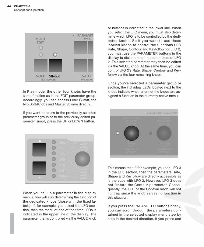
44 CHAPTER 6Concept and Operation
In Play mode, the other four knobs have thesame function as in the EDIT parameter group.Accordingly, you can access Filter Cutoff, thetwo Soft-Knobs and Master Volume directly.
If you want to return to the previously selectedparameter group or to the previously edited pa-rameter, simply press the UP or DOWN button.
When you call up a parameter in the displaymenus, you will also determining the function ofthe dedicated knobs (those with the fixed la-bels). If, for example, you select the LFO sec-tion, then the menu of one of the three LFOs isindicated in the upper line of the display. Theparameter that is controlled via the VALUE knob
or buttons is indicated in the lower line. Whenyou select the LFO menu, you must also deter-mine which LFO is to be controlled by the dedi-cated knobs. So if you want to use theselabeled knobs to control the functions LFORate, Shape, Contour and Keyfollow for LFO 2,you must use the PARAMETER buttons in thedisplay to dial in one of the parameters of LFO2. This selected parameter may then be editedvia the VALUE knob. At the same time, you cancontrol LFO 2's Rate, Shape, Contour and Key-follow via the four remaining knobs.
Once you've selected a parameter group orsection, the individual LEDs located next to theknobs indicate whether or not the knobs are as-signed a function in the currently active menu.
This means that if, for example, you edit LFO 3in the LFO section, then the parameters Rate,Shape and Keyfollow are directly accessible asis the case with LFO 2. However, LFO 3 doesnot feature the Contour parameter. Conse-quently, the LED of the Contour knob will notlight up since the knob serves no function inthis situation.
If you press the PARAMETER buttons briefly,you can scroll through the parameters con-tained in the selected display menu step bystep in the desired direction. If you press and
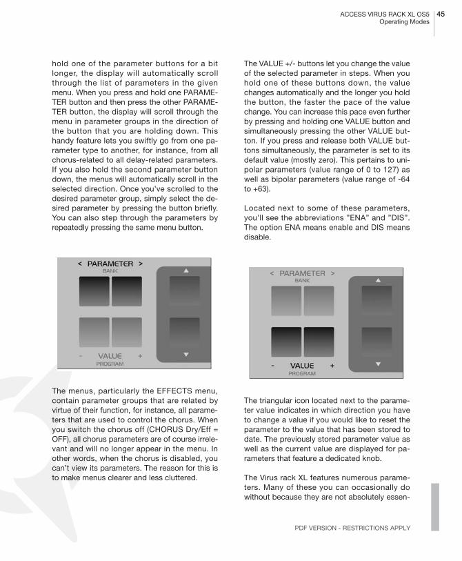
ACCESS VIRUS RACK XL OS5 45Operating Modes
PDF VERSION - RESTRICTIONS APPLY
hold one of the parameter buttons for a bitlonger, the display will automatically scrollthrough the list of parameters in the givenmenu. When you press and hold one PARAME-TER button and then press the other PARAME-TER button, the display will scroll through themenu in parameter groups in the direction ofthe button that you are holding down. Thishandy feature lets you swiftly go from one pa-rameter type to another, for instance, from allchorus-related to all delay-related parameters.If you also hold the second parameter buttondown, the menus will automatically scroll in theselected direction. Once you’ve scrolled to thedesired parameter group, simply select the de-sired parameter by pressing the button briefly.You can also step through the parameters byrepeatedly pressing the same menu button.
The menus, particularly the EFFECTS menu,contain parameter groups that are related byvirtue of their function, for instance, all parame-ters that are used to control the chorus. Whenyou switch the chorus off (CHORUS Dry/Eff =OFF), all chorus parameters are of course irrele-vant and will no longer appear in the menu. Inother words, when the chorus is disabled, youcan’t view its parameters. The reason for this isto make menus clearer and less cluttered.
The VALUE +/- buttons let you change the valueof the selected parameter in steps. When youhold one of these buttons down, the valuechanges automatically and the longer you holdthe button, the faster the pace of the valuechange. You can increase this pace even furtherby pressing and holding one VALUE button andsimultaneously pressing the other VALUE but-ton. If you press and release both VALUE but-tons simultaneously, the parameter is set to itsdefault value (mostly zero). This pertains to uni-polar parameters (value range of 0 to 127) aswell as bipolar parameters (value range of -64to +63).
Located next to some of these parameters,you’ll see the abbreviations ”ENA” and ”DIS”.The option ENA means enable and DIS meansdisable.
The triangular icon located next to the parame-ter value indicates in which direction you haveto change a value if you would like to reset theparameter to the value that has been stored todate. The previously stored parameter value aswell as the current value are displayed for pa-rameters that feature a dedicated knob.
The Virus rack XL features numerous parame-ters. Many of these you can occasionally dowithout because they are not absolutely essen-

46 CHAPTER 6Concept and Operation
tial to basic sound programming, and they dotend to make the device a little more challeng-ing to handle. EXPERT mode can solve thisproblem. It lets hide and show rarely used pa-rameters in the display menus. You'll find thedisplay for EXPERT mode in the ARP/CTRLmenu; it is the last parameter in the list. In thechapter "The Parameters", those parametersthat belong to EXPERT mode are labeled [XP].
The MULTI mode parameters feature a dedicat-ed menu called the Multi Edit menu. Access itby pressing the Multi button while the device isin MULTI mode. The LED located over the MUL-TI button will light up to indicate that the MultiEdit menu is active. Press the MULTI buttonagain to return to normal Play mode. If the de-vice is in MULTI-SINGLE mode, press the MUL-TI and SINGLE buttons simultaneously toaccess the Multi Edit menu. It suffices to presseither the MULTI or SINGLE button to return tonormal Play mode from MULTI-SINGLE mode.
DISPLAY OF VALUESWhen a menu is active, different display optionsare available for parameters with a dedicatedknob. These can be selected under the menuitem KNOB DISPLAY in the CTRL menu:
- OFF Knob movements are not displayed; thecurrent contents of the display remain intactwhen you turn a knob.
- ON The lower row of the display is beingoverwritten by the parameter's value.
- SHORT When you turn a knob, the currentcontents of the lower display line are brieflyoverwritten by data representing the changein parameter value; once the action is com-pleted, the original contents reappear in thelower display line.
- LONG Same as SHORT, except that - youguessed it - the display shows the knob datafor a longer period of time.
- ON The contents of the display are overwrit-ten when you turn a knob; the original menudoes not reappear in the display.
01111111111111111112
1 SYSTEM KnobDispl Short≤ 61111111111111111154
� ALL ABOUT THE MEMORY
STOREThe mode structure of SINGLE, MULTI andMULTI SINGLE MODE is mirrored in the STOREfunctions: In SINGLE MODE, STORE saves thecurrent SINGLE PROGRAM; in MULTI MODE,STORE saves the current MULTI PROGRAM;and in MULTI SINGLE MODE, the SINGLEPROGRAM of the current PART is stored.
The STORE process is always the same regard-less of the operating mode: Press STORE. Youthen gain access to the STORE menu. Thereyou can use the PARAMETER buttons to moveamong the individual letters in the lower nameentry line and the number of the destined mem-ory location as well as the bank number in theupper line. Use the VALUE button to make en-tries. The term in the upper display line indi-cates the name of the memory location whichyou will overwrite when you store the program.

ACCESS VIRUS RACK XL OS5 47Random Patch Generator
PDF VERSION - RESTRICTIONS APPLY
Once all of the entries correspond to the datayou have in mind, press STORE again to con-clude the process and return to the previouslyactive operating mode of the Virus. If for what-ever reason you change your mind and want tocancel the operation, simply press SINGLE orMULTI to return to the previous operating modewithout storing the program.
� To belabor the point, when you store aMULTI program, only the content of the MULTIedit buffer is saved, not however the sound pro-grams in the PARTs. These must be stored indi-vidually in MULTI SINGLE mode.
If you want to store the SINGLE programs in thePARTs to their original slots in the SINGLEbanks all at the same time, simply press STOREand 1 C126 - Init
01111111111111111112
1 C126 - Init [STORE] TO...61111111111111111154
COMPAREWhen you press STORE and then UP or DOWN,you will activate Compare mode. After you haveprogrammed or edited a SINGLE sound, Com-pare mode lets you hear the unedited soundthat was originally stored in this memory slot.Press UP or DOWN repeatedly to switch backand forth between the Compare sound and theedited sound so that you can - surprise, sur-prise – compare the two sounds. Use the PA-RAMETER/BANK buttons and the VALUEbuttons to step through the bank and programnumbers of the Compare sound. This lets yousearch for a new memory slot for the editedsound and, at the same time, hear the soundthat you will overwrite. The edited sound is notmodified or overwritten during this process.Press STORE to do just that to the edited sound– store it. Press MULTI or SINGLE to quit theSTORE process and/or exit Compare mode.
01111111111111111112
1 C126 -Init - compare 61111111111111111154
� RANDOM PATCH GENERATOR
RANDOM PATCHESThe RANDOM PATCH GENERATOR can beused to generate a new sound automatically ora modify an existing sound at random. The PARDEPTH and AMOUNT parameters let you deter-mine how radically the sound is changed. De-pending on the values that you set here, theRANDOM PATCH GENERATOR will do anything

48 CHAPTER 6Concept and Operation
from modifying sound parameters subtly tomorphing one sound into an entirely differentsound.
The RANDOM PATCH GENERATOR is activatedwhen you presses the button STORE while thedisplay is showing one of the two RANDOM pa-rameters. The results of the computation arestored in the Edit buffer and can be heard im-mediately. You can also press STORE severaltimes in order to create successive sound chan-ges. If you want store a sound permanently thatthe RANDOM PATCH GENERATOR has crea-ted, simply save it to a SINGLE memory slot inthe usual manner. For this purpose, press theSINGLE button to activate PLAY mode (SINGLEmode or MULTI-SINGLE mode) so that theSTORE button’s original function is restored.
If you want to restart the process with the origi-nal sound settings, simply return to PLAY modeback and select the desired sound again.
PAR DEPTHThis parameter determines the number ofsound parameters that are influenced by theRANDOM PATCH GENERATOR. If you enter alow value for PAR DEPTH, just a few parame-ters will be modified. Beyond that, the mannerin which the few parameters are edited assuresthat the sound is manipulated “organically”.This simply means that it isn’t bent radically sothat, for example, the given sound can still beplayed “tonally”.
As you increase the values for PAR DEPTH, oth-er parameters that have a greater impact on thetimbre of the sound are changed. At higher val-ues, the RANDOM PATCH GENERATOR tendsto generate noise-like sounds or special effects.
01111111111111111112
1 RANDOM [STORE] ParaDepth 0≤61111111111111111154
AMOUNTThis parameter determines the intensity of theRANDOM PATCH GENERATOR’s effect on thesound parameters. At lower values, soundchanges are fairly subtle, but you can intensifythe effect by repeatedly pressing the STOREbutton. Higher values introduce fundamentalchanges to the sound.
01111111111111111112
1 RANDOM [STORE] Amount 0≤61111111111111111154
� Be aware that RANDOM PAR DEPTH andRANDOM AMOUNT are not actual sound para-meters. They merely set the parameters for theRANDOM PATCH GENERATOR and only takeeffect when the RANDOM PATCH GENERATORis activated. Not until then will the sound bechanged.

ACCESS VIRUS RACK XL OS5 49Modmatrix And Soft Knobs
PDF VERSION - RESTRICTIONS APPLY
� MODMATRIX AND SOFT KNOBS
CREATING MODULATIONS VIA ASSIGNAs a rule, it is of course desirable to be able tocreate modulation routing configurations on asynthesizer. In other words, you want to enjoythe freedom to combine different modulationsources and destinations as you see fit. Some-times you may come up with ideas for standardmodulations that the ”hard-wired” factory mod-ulation routing options simply can’t satisfy. Thisis why we opted to equip the Virus with a versa-tile Modulation Matrix – you’re sure to find it awelcome addition. On the Virus, you can createmodulation routing configurations freely as yousee fit using ASSIGN options. They are locatedin the EDIT menu, where they appear under thename of – you guessed it – ASSIGN).
The three ASSIGN options let you control up tosix modulation destinations via up to threemodulation sources. Simply go to ASSIGN, se-lect one of the modulation sources (SOURCE)and one or several modulation destinations(DESTINATION). Each of these configurationsfeatures a parameter that determines modula-tion intensity (AMOUNT). ASSIGN 1 can controlone modulation destination, ASSIGN 2 cancontrol two and ASSIGN 3 can control threemodulation destinations, each with independ-ent AMOUNTs.
These ASSIGN options serve several purposes:for one, they let you assign an external MIDIcontroller, for example, the keyboard’s modula-tion wheel, to the desired parameter. You canalso chose to use the sound generator’s internalmodulators, such as LFOs and envelopes, asmodulation sources. The control range of thesource may be limited via the AMOUNT values
or inverted so that the modulation occurs strict-ly within the desired value range for the targetparameter. For your target parameters, you canchose from among virtually all sound parame-ters that feature an infinitely variable controlrange – ergo, you have more than 100 modula-tion destinations at your disposal! Since thesources and destinations may be selected inde-pendently, you may even modulate a single pa-rameter by using up to three modulationsources simultaneously. For this purpose, thecontrol signals of the modulation sources areadded up or overlapped. Conversely, you canalso modulate up to six parameters with justone controller, which gives you all kinds of so-phisticated sound morphing options. For thispurpose, select the same source for all threeASSIGN options so that it modulates all sixpossible destinations. This lets you radically re-shape sounds and even transform or morphthem into entirely different sounds.
01111111111111111112
1 ASSIGN Source OFF≤ 61111111111111111154
� You’ll find a list of available sources andDESTINATIONS in the appendix. [“Appendix”on page 157]
SOFT KNOBSThe Virus is equipped with two knobs that, rath-er than being dedicated to predefined tasks,may be assigned to different parameters byyou, the user. This option is quite handy, for itlets you control directly the many menu param-eters that do not feature a dedicated knob.

50 CHAPTER 6Concept and Operation
These Soft-Knobs operate in three differentmodes:
- GLOBAL The knob controls the parameterthat you have set to Global in the Soft Knobmenu regardless of what the other settingsand the selected SINGLE program may be.
- SINGLE The knob controls the parameterthat you have set to Single in the Soft Knobmenu. The setting for this parameter is storedin the SINGLE program and called up when-ever you select this program. If, however, youhave not selected a parameter for this pro-gram (Soft Knob Single = OFF), the setting forSoft Knob Global is automatically enabled.
The setting for the actual Soft Knob mode isglobal. Under normal circumstances, youshould set Soft Knob mode to ”Single” becausethis is the most versatile mode. When you se-lect a SINGLE sound whose Soft Knob mode isset to ”Single”, this setting is of course ena-bled. If not, Global Soft Knob mode is enabled.
01111111111111111112
1 Soft Knob 1 Mode Single≤ 61111111111111111154
� MASTER CLOCK AND MIDI-CLOCK
The Virus is equipped with a global clock gener-ator that lets you sync the LFOs, arpeggiatorsand delay up to a common song tempo andrhythm. The clock generator works either inter-nally with a freely variable speed or it can, inturn, by synced up to the MIDI clock of an ex-ternal sequencer. This synchronization occursautomatically when the device receives a MIDIclock signal via its MIDI In. You can vary thespeed of the clock generator within a range of63 to 190 BPM (beats per minute) via CLOCKTEMPO. When the device is synchronized viaMIDI clock, the clock generator automaticallyaccepts the speed dictated by the connectedsequencer; the internal tempo setting is in thiscase meaningless and thus disabled. The indi-vidual sections of the Virus are synced up to theclock generator at rhythmic intervals such as 1/16, 1/4 and so forth. These values may be as-signed individually for every section. (AR-PEGGIATOR CLOCK, CLOCK LFO 1, CLOCKLFO 2, CLOCK LFO 3, DELAY CLOCK, see therespective sections).
In SINGLE MODE, CLOCK TEMPO pertains tothe current SINGLE PROGRAM and is storedalong with it. In MULTI MODE, the CLOCKTEMPO settings for the involved SINGLE PRO-GRAMs are ignored. Instead, all involved SIN-GLE PROGRAMs are controlled via the sameclock generator. Its CLOCK TEMPO is saved inthe MULTI PROGRAM (as are the settings forthe global delay effect).
This feature lets you control the LFOs and ar-peggiators of several MULTI PARTS in a com-mon rhythmic context.
� A “c” symbol will appear in the display
ACCESS VIRUS RACK XL OS5 51The Effects Section
PDF VERSION - RESTRICTIONS APPLY
� When the Virus is receiving MIDI Clock data.If you’re sure you do NOT want the device to besynchronized automatically to MIDI clock, setMIDI CLOCK RX to Off (in the CTRL menu).) Toavoid confusion, please keep in mind that MIDIClock is not the same thing as MIDI Time Code.The latter doesn’t deal with tempo at all but withtime-related information structured in hours,minutes, seconds, etc. which is of no benefit toyou in this context.
� THE EFFECTS SECTION
For every SINGLE program and every PART,you can access two stereo effects individually.You’ll find these effects – analog boost andchorus – in the aptly named EFFECTS menu.
The vocoder and the delay/reverb section areeach available just once, but you can addressthem individually via the PARTs’ Effect Send pa-rameter. In the signal path, all effects are con-nected in series in accordance with theirsequence in the Effects menu.
Each SINGLE program contains its own set-tings for the delay/reverb section. In MULTImode, the sound programs involved share thesame delay/reverb section. For this reason, theparameter values are determined by the set-tings of the currently active MULTI program.[“The Multi Mode Parameters” on page 113].
� AUDIO INPUTS
You can also opt to use external audio signalsin place of the on-board oscillators for thesound programs or MULTI PARTs. The Virus isequipped with two inputs for external signals.You can route these to its sound generatingcomponents (the filters, the saturation stage aswell as the volume and panorama stage) orpatch them directly to the effects section of theVirus. External audio signals may also be usedas carrier or modulator signals for the vocoder.Any PART that you use to process an externalaudio signal in MULTI mode can, like every oth-er PART, be routed freely to one or two of thefour audio outputs.
The Virus rack XL is equipped with two audioinputs on the back panel. Additionally the leftinput is accessible on the front panel. When youplug a cord into the front input, the rear left in-put is disabled.
As a rule, when you’re processing external au-dio signals, you need to distinguish betweenthe following two operating modes:
- DYNAMIC To make external signals audiblein this operating mode, the volume envelopemust be triggered via a note. This option, forexample, lets you create typical gater effects.INPUT Dynamic mode is also polyphonic. Ifyou set the KEYFOLLOW value for the filtersto 100%, the resonant frequencies of the fil-ters and oscillators can be played in a tem-pered manner via the INPUT signal. This letsyou play entire chords as well as arpeggiatorlines using the filters. The noise generator isalso active in INPUT mode.
- STATIC In Input Static mode, the externalaudio signals are audible via the output with-out having to trigger a note. Bear in mind thatthe oscillators as well as all functions thathave to do with trigger and pitch are disabled

52 CHAPTER 6Concept and Operation
(envelopes, LFO Env mode, Keyfollow...) InINPUT Static mode. When you set the deviceto this mode, one voice of the Virus is activat-ed automatically. If you select a stereo source(L+R) for INPUT Select, two voices are acti-vated much like in UNISON mode: Twin. Inthis case, you can also use the UNISON PanSpread parameter to determine the basicwidth of the panorama and UNISON LFOPhase to shift the LFO phase position be-tween the voices.
- TOEFFECTS An alternative to INPUT Staticmode, here the audio signal is routed directlyto the effects section of the SINGLE programor PART. This mode doesn’t use the voices ofthe Virus, which means that its polyphonicperformance remains fully intact and availa-ble. The filter section is unavailable in thismode.
01111111111111111112
1 INPUT Mode Dynamic≤ 61111111111111111154
OSC VOLUME / INPUTWhen one of the two INPUT modes is activated,the OSC VOL parameter rather than the oscilla-tors controls the level of the INPUT signal infront of the Filter section and of course also thegain of the SATURATION stage. In INPUT Dy-namic mode, the level increases quite rapidlywhen you play several voices polyphonically.The reason for this is that – in contrast to whenyou’re dealing with several oscillator signals –the voices are correlated because they are re-ceiving an identical input signal. In the eventthat the Virus generates distortion when you’redealing with this type of signal routing set-up,be sure to back off the input level a tad via theOSC VOL knob.
INPUT GLOBAL SETTINGSIn the Input menu, you'll find a gain switch (IN-PUT Gain) that increases the input signal by 20decibels before it is sent to the digital analogconverter. This means that with the propercords you can connect a microphone, an elec-tric guitar or a record player directly to the Virusrack XL. However, to attain the best possiblesound quality, it is advisable to patch the signalinto an appropriate signal processor such as amicrophone preamplifier, a mixer, or a guitarpreamp before you route it into the input of theVirus. Please turn down the Master Volumeknob before you turn input gain up. Be awarethat boosting the signal by 20 decibels increas-es the level tenfold!
Additionally the Virus is equipped with an ampli-fier stage (INPUT Boost), that can boost the sig-nal level of the two inputs continuously by up to36 dB. The signal is boosted in the digital sec-tion of the Virus, so the noise level of the ana-log-digital converters increases automatically.Consequently you should dial in the cleanest,loudest possible signals at the external soundgenerator, or use the INPUT Gain switch.
Since record players have a characteristic fre-quency response, we equipped the Virus rackXL with a suitable Phono equalizer. It may beactivated via the "INPUT Phono" parameter.
INPUT LEVEL INDICATOR Alternatively, the RATE LEDs of LFO 1 and 2can also serve as level indicators for the left andright external audio inputs. The Virus automati-cally switches to this level indicator mode whenthe selected SINGLE program accesses the ex-ternal audio inputs. The LEDs will flash rapidlyto indicate that the inputs are being overloaded.You should dial in the proper level on the devicethat is sending the analog signals. The reasonfor that you want to feed the highest possible

ACCESS VIRUS RACK XL OS5 53Audio Routing
PDF VERSION - RESTRICTIONS APPLY
clean signal level to the analog-to-digital con-verters of the Virus so that they will deliver thebest possible performance. [“LED MODE” onpage 128]
� AUDIO ROUTING
THE AUDIO OUTPUTS In MULTI mode, you can choose a mono orstereo audio output in the OUTPUT Selectmenu independently for every PART.
In contrast to the majority of other effects, thedelay/reverb section is not available individuallyfor each PART. Instead, it processes the signalsof the PARTs collectively. You can, however,control the intensity of the effect individually foreach PART using the respective Effect Send pa-rameter. Consequently, the delay/reverb sectionhas just one signal output, which cannot be dis-tributed to the outputs of the individual PARTs.
This is why, for example, the delay effect of aPART that is routed to the pair of outputs la-beled OUT 2 will still be audible on OUT 1. Thiscan be desirable yet may also lead to confu-sion. To encourage the former and prevent thelatter, set the Effect Send parameter of thePART to zero when you’re using individual out-puts.
In MULTI mode, the delay/reverb section fea-ture its own OUTPUT Select that is independentof the PARTs.
� SOUND CATEGORIES
The Virus gives you the option of classing thestored SINGLE sounds in categories. With thebenefit of these categories, you’ll be able to finda desired sound much faster.
You have the following categories at your dis-posal:
Off, Lead, Bass, Pad, Decay, Plug, Acid, Clas-sic, Arpeggiator, Effects, Drums, Percussion, In-put, Vocoder, Favourite ...
Every SINGLE sound can be assigned to up totwo categories by means of the parametersCATEGORY 1 and CATEGORY 2. For example,you could assign the attributes "Bass" and "Ac-id" or "Lead" and "Favorite 1" to a given sound.These categories may be changed at any timeand can be stored along with the sound. Thefactory sounds are assigned default categories.
Once you’ve assigned categories, you cansearch for the sounds within a specific categoryin SINGLE mode and MULTI-SINGLE mode:
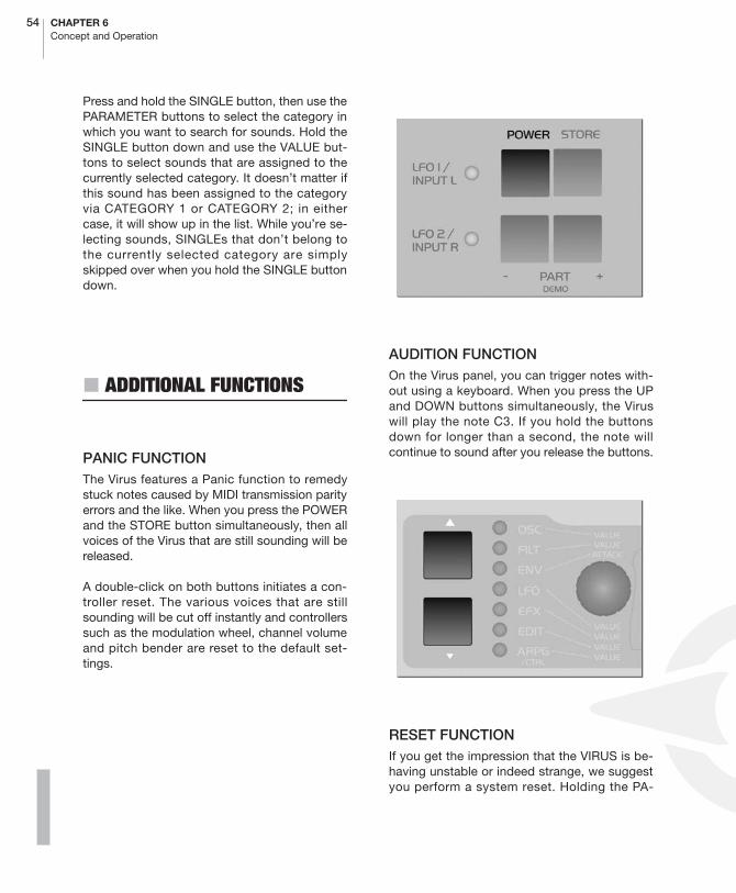
54 CHAPTER 6Concept and Operation
Press and hold the SINGLE button, then use thePARAMETER buttons to select the category inwhich you want to search for sounds. Hold theSINGLE button down and use the VALUE but-tons to select sounds that are assigned to thecurrently selected category. It doesn’t matter ifthis sound has been assigned to the categoryvia CATEGORY 1 or CATEGORY 2; in eithercase, it will show up in the list. While you’re se-lecting sounds, SINGLEs that don’t belong tothe currently selected category are simplyskipped over when you hold the SINGLE buttondown.
� ADDITIONAL FUNCTIONS
PANIC FUNCTIONThe Virus features a Panic function to remedystuck notes caused by MIDI transmission parityerrors and the like. When you press the POWERand the STORE button simultaneously, then allvoices of the Virus that are still sounding will bereleased.
A double-click on both buttons initiates a con-troller reset. The various voices that are stillsounding will be cut off instantly and controllerssuch as the modulation wheel, channel volumeand pitch bender are reset to the default set-tings.
AUDITION FUNCTION On the Virus panel, you can trigger notes with-out using a keyboard. When you press the UPand DOWN buttons simultaneously, the Viruswill play the note C3. If you hold the buttonsdown for longer than a second, the note willcontinue to sound after you release the buttons.
RESET FUNCTIONIf you get the impression that the VIRUS is be-having unstable or indeed strange, we suggestyou perform a system reset. Holding the PA-
ACCESS VIRUS RACK XL OS5 55Additional Functions
PDF VERSION - RESTRICTIONS APPLY
RAMETER LEFT button while switching the VI-RUS on, performs a system reset. No data willbe lost during this procedure, although someglobal system settings as ”Global Channel” willbe reset.

56 CHAPTER 6Concept and Operation

The Parameters
58 CHAPTER 7The Parameters
OSC Section (Encoder)
� OSCILLATOR 1
The following section lists all parameters in theVirus, each with a brief definition or explanation.
The function of the Encoders depends on theselected section and the currently active dis-play menu. If the given Encoder does not havean assignment, the corresponding LED on thefront panel will extinguish. If no menu is activat-ed (none of the seven section LEDs is illuminat-ed) the Encoder assignments are determined bythe Edit section.
SHAPEThis control feature lets you determine thewaveshape for the WAVE section (one of 64variable spectral waveshapes). The waveshapeis infinitely variable from sawtooth through topulse waves. Wave or pulse width selection isexecuted via the SHAPE and WAVE SEL/PWcontrol features (see appropriate section): IfSHAPE has a value less than the value of the“center position”, then WAVE SEL/PW deter-mines the waveshape; if the SHAPE value ishigher than that of the center position, thenWAVE SEL/PW determines the pulse width.
WAVE SEL/PWhas two functions, depending on the SHAPE(see appropriate section) value:
� When SHAPE has a value lower than that ofthe “center position”, then WAVE SEL/PW letsyou select from the 64 spectral waveshapesavailable in the ROM of the Virus. Waveshape 1is a sine wave; No. 2 a triangle, the remainder ofthe waves feature different combinations of fre-quencies.
� When the SHAPE value is higher than that ofthe “center position”, then WAVE SEL/PW de-termines the pulse width: At the far left positionthe pulse width is 50%, at the far right it is 0%,which means the wave no longer oscillates.
SEMITONEDetermines the interval between the second os-cillator and the first oscillator: Control range +/-48 semitones, assigned in semitone steps.
� OSCILLATOR 2
SHAPESame as OSCILLATOR 1; see paragraph above.
WAVE SEL/PWSame as OSCILLATOR 1; see paragraph above.

ACCESS VIRUS RACK XL OS5 59Oscillator 3
PDF VERSION - RESTRICTIONS APPLY
SEMITONESame as OSCILLATOR 1; see paragraph above.
DETUNEDetunes the second oscillator relatively to thefirst. With this parameter, you can dial in every-thing from slight deviations in pitch to majorfluctuations between the two oscillators.
� OSCILLATOR 3
OSCILLATOR-3 SEMITONE Transposes Oscillator 3 in semitone steps. Con-trol range: +/-4 octaves. (Not available if OS-CILLATOR 3 MODE = “OFF” or “SLAVE”.)
01111111111111111112
1 OSCILLATOR 3 Semitones +0≤ 61111111111111111154
OSCILLATOR-3 DETUNEDetunes the third oscillator relatively to the first.With this parameter, you can dial in everythingfrom slight deviations in pitch to major fluctua-tions relatively to the other oscillators.
01111111111111111112
1 OSCILLATOR 3 Detune +0≤ 61111111111111111154

60 CHAPTER 7The Parameters
� SUB OSCILLATOR
VOLUMEDetermines the volume level of the SubOscilla-tor.
01111111111111111112
1 SUBOSCILLATOR Volume 30≤61111111111111111154
SHAPESwitches the waveshape of the SubOscillatorbetween SQUARE and TRIANGLE.
01111111111111111112
1 SUBOSCILLATOR Shape Square≤61111111111111111154
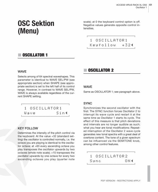
ACCESS VIRUS RACK XL OS5 61Oscillator 1
PDF VERSION - RESTRICTIONS APPLY
OSC Sektion (Menu)
� OSCILLATOR 1
WAVE
Selects among of 64 spectral waveshapes. Thisparameter is identical to WAVE SEL/PW (seeappropriate section) when SHAPE (see appro-priate section) is set to the left half of its controlrange. However, in contrast to WAVE SEL/PW,WAVE is always available regardless of the cur-rent SHAPE setting.
01111111111111111112
1 OSCILLATOR1 Wave Sin≤61111111111111111154
KEY FOLLOWDetermines the intensity of the pitch control viathe keyboard: At the value +32 (standard set-ting) the oscillator is controlled normally, i.e. theoctave you are playing is identical to the oscilla-tor octave; at +63 every ascending octave youplay transposes the oscillator upwards by twooctaves (whole note scale); +15 transposes theoscillator upwards by one octave for every twoascending octaves you play (quarter note
scale); at 0 the keyboard control option is off.Negative values generate opposite control in-tensities.
01111111111111111112
1 OSCILLATOR1 Keyfollow +32≤61111111111111111154
� OSCILLATOR 2
WAVE
Same as OSCILLATOR 1; see paragraph above.
SYNCSynchronizes the second oscillator with thefirst: The SYNC function forces Oscillator 2 tointerrupt its wave cycle and restart it at thesame time as Oscillator 1 starts its cycle. Theeffect of this measure is that pitch deviationsand intervals are no longer audible as such;what you hear are tonal modifications: Repeat-ed interruption of the Oscillator 2 wave cyclegenerates new tonal spectra with a great deal ofovertone content. The tone of a given spectrumcan be influenced via the SEMITONE knob,among other control features.
01111111111111111112
1 OSCILLATOR2 Sync ON≤61111111111111111154
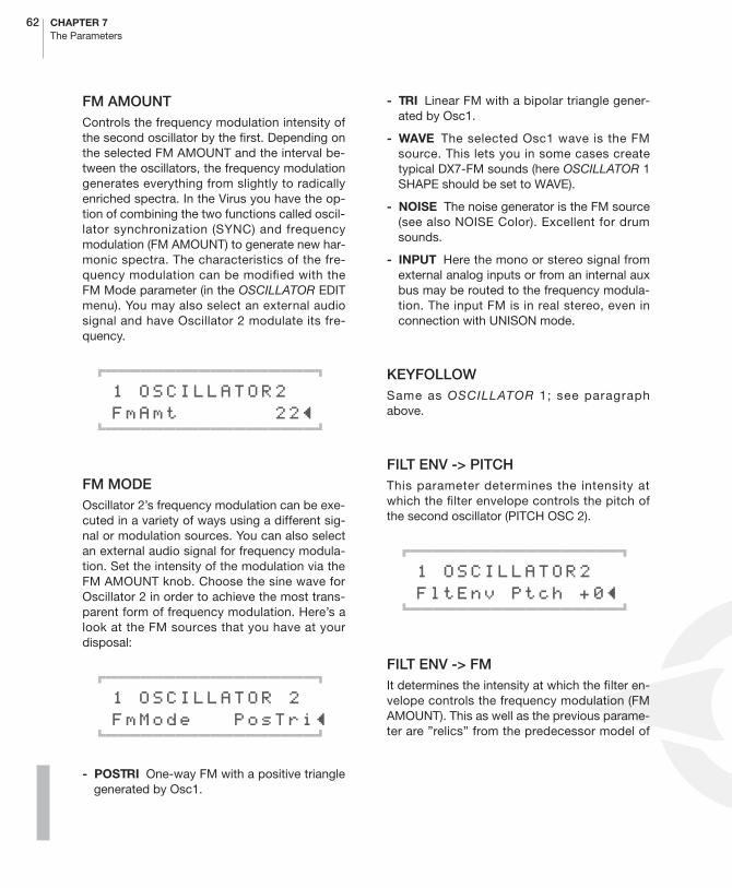
62 CHAPTER 7The Parameters
FM AMOUNTControls the frequency modulation intensity ofthe second oscillator by the first. Depending onthe selected FM AMOUNT and the interval be-tween the oscillators, the frequency modulationgenerates everything from slightly to radicallyenriched spectra. In the Virus you have the op-tion of combining the two functions called oscil-lator synchronization (SYNC) and frequencymodulation (FM AMOUNT) to generate new har-monic spectra. The characteristics of the fre-quency modulation can be modified with theFM Mode parameter (in the OSCILLATOR EDITmenu). You may also select an external audiosignal and have Oscillator 2 modulate its fre-quency.
01111111111111111112
1 OSCILLATOR2 FmAmt 22≤61111111111111111154
FM MODEOscillator 2’s frequency modulation can be exe-cuted in a variety of ways using a different sig-nal or modulation sources. You can also selectan external audio signal for frequency modula-tion. Set the intensity of the modulation via theFM AMOUNT knob. Choose the sine wave forOscillator 2 in order to achieve the most trans-parent form of frequency modulation. Here’s alook at the FM sources that you have at yourdisposal:
01111111111111111112
1 OSCILLATOR 2 FmMode PosTri≤61111111111111111154
- POSTRI One-way FM with a positive trianglegenerated by Osc1.
- TRI Linear FM with a bipolar triangle gener-ated by Osc1.
- WAVE The selected Osc1 wave is the FMsource. This lets you in some cases createtypical DX7-FM sounds (here OSCILLATOR 1SHAPE should be set to WAVE).
- NOISE The noise generator is the FM source(see also NOISE Color). Excellent for drumsounds.
- INPUT Here the mono or stereo signal fromexternal analog inputs or from an internal auxbus may be routed to the frequency modula-tion. The input FM is in real stereo, even inconnection with UNISON mode.
KEYFOLLOWSame as OSCILLATOR 1; see paragraphabove.
FILT ENV -> PITCHThis parameter determines the intensity atwhich the filter envelope controls the pitch ofthe second oscillator (PITCH OSC 2).
01111111111111111112
1 OSCILLATOR2 FltEnv~Ptch +0≤61111111111111111154
FILT ENV -> FMIt determines the intensity at which the filter en-velope controls the frequency modulation (FMAMOUNT). This as well as the previous parame-ter are ”relics” from the predecessor model of
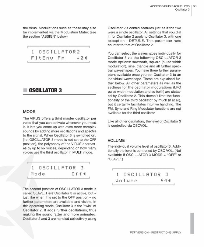
ACCESS VIRUS RACK XL OS5 63Oscillator 3
PDF VERSION - RESTRICTIONS APPLY
the Virus. Modulations such as these may alsobe implemented via the Modulation Matrix (seethe section ”ASSIGN” below).
01111111111111111112
1 OSCILLATOR2 FltEnv~Fm +0≤61111111111111111154
� OSCILLATOR 3
MODE
The VIRUS offers a third master oscillator pervoice that you can activate whenever you needit. It lets you come up with even more complexsounds by adding more oscillations and spectrato the signal. When Oscillator 3 is switched on,(i.e. OSCILLATOR 3 mode is not set to the OFFposition), the polyphony of the VIRUS decreas-es by up to six voices, depending on how manyvoices use the third oscillator in MULTI mode.
01111111111111111112
1 OSCILLATOR 3 Mode Off≤ 61111111111111111154
The second position of OSCILLATOR 3 mode iscalled SLAVE. Here Oscillator 3 is active, but –just like when it is set to the OFF position – nofurther parameters are available and visible. Inthis operating mode, Oscillator 3 is the ”twin” ofOscillator 2. It adds further oscillations, thusmaking the sound fatter and more animated.Oscillator 2 and 3 are handled collectively using
Oscillator 2’s control features just as if the twowere a single oscillator. All settings that you dialin for Oscillator 2 apply to Oscillator 3, with oneexception – DETUNE. This parameter runscounter to that of Oscillator 2.
You can select the waveshapes individually forOscillator 3 via the following OSCILLATOR 3mode options: sawtooth, square (pulse widthmodulation), sine, triangle and all further spec-tral waveshapes. You have three further param-eters available once you set Oscillator 3 to anindividual waveshape. These are explained fur-ther below. All other parameters as well as thesettings for the oscillator modulations (LFOpulse width modulation and so forth) are dictat-ed by Oscillator 2. This doesn’t limit the func-tionality of the third oscillator by much (if at all),but it certainly facilitates intuitive handling. TheFM, Sync and Ring Modulator functions are notavailable for the third oscillator.
Like all other oscillators, the level of Oscillator 3is controlled via OSCVOL.
VOLUMEThe individual volume level of oscillator 3. Addi-tionally the level is controlled by OSC VOL. (Notavailable if OSCILLATOR 3 MODE = “OFF” or“SLAVE”.)
01111111111111111112
1 OSCILLATOR 3 Volume 64≤ 61111111111111111154

64 CHAPTER 7The Parameters
� OSCILLATORS
OSC BALDetermines the balance between the Oscillators1 and 2 volume level.
01111111111111111112
1 OSCILLATORS Balance 64≤61111111111111111154
VOLUMEThis knob has two functions:
� In the left half of its control range up to thecenter position (MIDI value 64), OSC VOL deter-mines the master volume of the three oscillatorsprior to the filter section input. The Noise Gen-erator and the Ringmodulator are not affectedby the master volume knob OSC VOL. Their lev-el is controlled separately in the OSCILLATOREDIT menu (see appropriate section).
� In the right half of the control range from thecenter position to the far right, OSC VOL in-creases the saturation intensity (Gain) for the in-put of the SATURATION stage (see appropriatesection); however this adjustment is compen-sated post-SATURATION stage so that whenyou adjust the gain you are not actually increas-ing the volume, only manipulating the tonalspectrum in terms of saturation. The intensity ofthe remaining DSP effects available in the SAT-URATION Stage is controlled via the OSC VOLknob.
PHASE INITThis feature lets you select the oscillator phaseposition at the start of a note. At a value of 0, alloscillators oscillate freely much like in a tradi-tional analog synthesizer. At values of 1 andhigher, Oscillator 1 starts the note with a phaseangle of 0, whereas the phase position of thesecond oscillator is shifted increasingly at as-cending values. The Phase position of oscillator3 is shifted to the opposite direction. With thisparameter, the attack phase of every note isidentical, which is a handy feature for program-ming drums and percussive sounds. In con-junction with Oscillator 3 and PHASE INIT, youcan create prominent overtones that are initiat-ed at the beginning of a note.
01111111111111111112
1 OSCILLATORS PhaseInit Off≤61111111111111111154
� RINGMODULATOR
VOLUMEThe ring modulator multiplies the output of bothoscillator 1 and 2 to create interesting soundswith rich enharmonic overtones. These over-tones are highly dependent on the frequencycoherence of both oscillators and it’s wave-forms. The frequency coherence can bechanged, for instance use the OSC2 SEMI-TONE parameter. If the RINGMODULATORVOLUME is zero, the ring modulator is switchedoff. OSC VOL does NOT affect the ring modula-

ACCESS VIRUS RACK XL OS5 65Noise
PDF VERSION - RESTRICTIONS APPLY
tor level. Therefore the original oscillator signalcan be levelled independently of the ring modu-lator.
01111111111111111112
1 RINGMODULATOR Volume 0≤61111111111111111154
� NOISE
NOISE VOLUME
The volume of the noise generator. As with thering modulator, the volume is idependent off theOSC VOL parameter.
COLORDetermines the sound of the Noise. Positive va-lues emphasis on high frequencies, negativevalues on the bass frequencies.
01111111111111111112
1 NOISE Color +0≤61111111111111111154
- MIDDLE Neutral (white noise, all frequen-cies are emphasised equally).
- NEGATIVE Lowpass (pink noise, dark andemphasised on bass frequencies).
- POSITIVE Highpass (bright and thin noise,emphasised on high frequencies).

66 CHAPTER 7The Parameters
Filter Section (Encoder)
CUTOFF
Determines the cutoff frequency of Filter-1 and2 (with exceptions; see CUTOFF 2).
CUTOFF 2 (OFFSET)Controls the cutoff frequency of Filter-2. Nor-mally, CUTOFF 2 does not operate absolutely,but relatively to CUTOFF: The cutoff frequencyof the second filter is subordinate to the CUT-OFF value you determined for the first filter.However you can use the CUTOFF 2 knob todial in a relative +/- deviation in frequencies, i.e.a higher or lower frequency (OFFSET). Whenyou set CUTOFF 2 to the center position, bothfilters have the same CUTOFF frequency. InFILTER EDIT Menu, you can access CUTOFF
LINK ON/OFF to sever the link between CUT-OFF and CUTOFF 2. In this case the two knobsCUTOFF and CUTOFF 2 are independent cutoffcontrols for Filters 1 and 2, respectively.
RESONANCEControls the resonance (also called filter feed-back or Q factor). Depending on the FILT SE-LECT setting, RESONANCE affects the firstfilter, the second filter or both filters.
ENV AMOUNTDetermines the modulation intensity of the cut-off frequency filter envelope. Depending on theFILT SELECT setting, ENV AMOUNT affects thefirst filter, the second filter or both filters. In con-trast to virtually all other modulation intensityparameters in the Virus, ENV AMOUNT is a uni-polar parameter. The polarity of the modulationcan be changed individually for each filter viathe ENV POLARITY function in the FILTER EDITmenu.
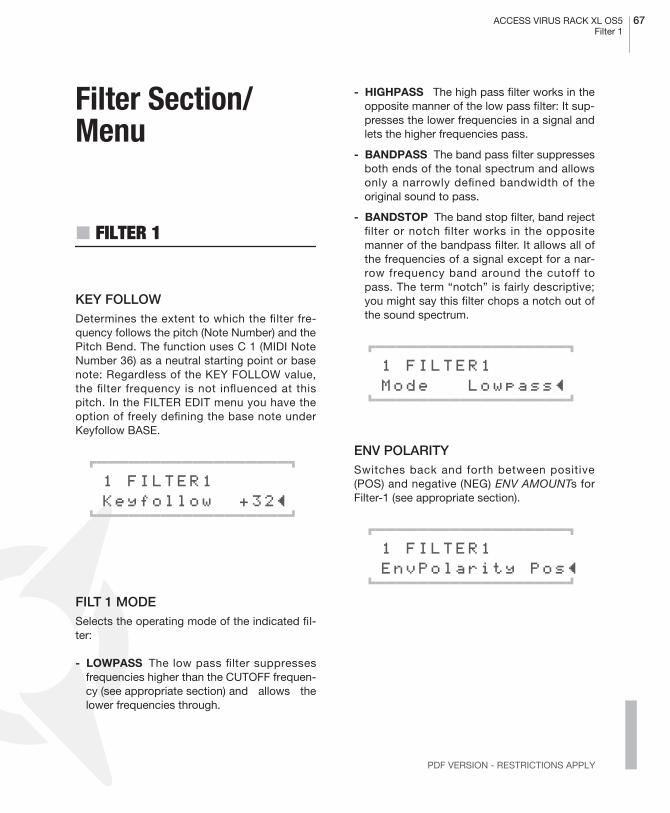
ACCESS VIRUS RACK XL OS5 67Filter 1
PDF VERSION - RESTRICTIONS APPLY
Filter Section/Menu
� FILTER 1
KEY FOLLOWDetermines the extent to which the filter fre-quency follows the pitch (Note Number) and thePitch Bend. The function uses C 1 (MIDI NoteNumber 36) as a neutral starting point or basenote: Regardless of the KEY FOLLOW value,the filter frequency is not influenced at thispitch. In the FILTER EDIT menu you have theoption of freely defining the base note underKeyfollow BASE.
01111111111111111112
1 FILTER1 Keyfollow +32≤61111111111111111154
FILT 1 MODESelects the operating mode of the indicated fil-ter:
- LOWPASS The low pass filter suppressesfrequencies higher than the CUTOFF frequen-cy (see appropriate section) and allows thelower frequencies through.
- HIGHPASS The high pass filter works in theopposite manner of the low pass filter: It sup-presses the lower frequencies in a signal andlets the higher frequencies pass.
- BANDPASS The band pass filter suppressesboth ends of the tonal spectrum and allowsonly a narrowly defined bandwidth of theoriginal sound to pass.
- BANDSTOP The band stop filter, band rejectfilter or notch filter works in the oppositemanner of the bandpass filter. It allows all ofthe frequencies of a signal except for a nar-row frequency band around the cutoff topass. The term “notch” is fairly descriptive;you might say this filter chops a notch out ofthe sound spectrum.
01111111111111111112
1 FILTER1 Mode Lowpass≤61111111111111111154
ENV POLARITYSwitches back and forth between positive(POS) and negative (NEG) ENV AMOUNTs forFilter-1 (see appropriate section).
01111111111111111112
1 FILTER1 EnvPolarity Pos≤61111111111111111154
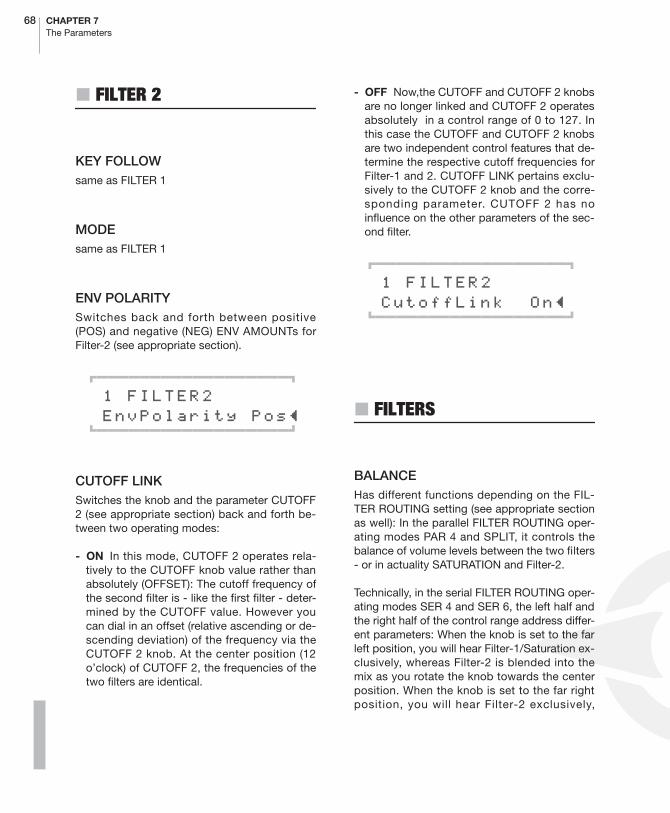
68 CHAPTER 7The Parameters
� FILTER 2
KEY FOLLOWsame as FILTER 1
MODEsame as FILTER 1
ENV POLARITYSwitches back and forth between positive(POS) and negative (NEG) ENV AMOUNTs forFilter-2 (see appropriate section).
01111111111111111112
1 FILTER2 EnvPolarity Pos≤61111111111111111154
CUTOFF LINKSwitches the knob and the parameter CUTOFF2 (see appropriate section) back and forth be-tween two operating modes:
- ON In this mode, CUTOFF 2 operates rela-tively to the CUTOFF knob value rather thanabsolutely (OFFSET): The cutoff frequency ofthe second filter is - like the first filter - deter-mined by the CUTOFF value. However youcan dial in an offset (relative ascending or de-scending deviation) of the frequency via theCUTOFF 2 knob. At the center position (12o’clock) of CUTOFF 2, the frequencies of thetwo filters are identical.
- OFF Now,the CUTOFF and CUTOFF 2 knobsare no longer linked and CUTOFF 2 operatesabsolutely in a control range of 0 to 127. Inthis case the CUTOFF and CUTOFF 2 knobsare two independent control features that de-termine the respective cutoff frequencies forFilter-1 and 2. CUTOFF LINK pertains exclu-sively to the CUTOFF 2 knob and the corre-sponding parameter. CUTOFF 2 has noinfluence on the other parameters of the sec-ond filter.
01111111111111111112
1 FILTER2 CutoffLink On≤61111111111111111154
� FILTERS
BALANCEHas different functions depending on the FIL-TER ROUTING setting (see appropriate sectionas well): In the parallel FILTER ROUTING oper-ating modes PAR 4 and SPLIT, it controls thebalance of volume levels between the two filters- or in actuality SATURATION and Filter-2.
Technically, in the serial FILTER ROUTING oper-ating modes SER 4 and SER 6, the left half andthe right half of the control range address differ-ent parameters: When the knob is set to the farleft position, you will hear Filter-1/Saturation ex-clusively, whereas Filter-2 is blended into themix as you rotate the knob towards the centerposition. When the knob is set to the far rightposition, you will hear Filter-2 exclusively,

ACCESS VIRUS RACK XL OS5 69Filters
PDF VERSION - RESTRICTIONS APPLY
whereas Filter-1/Saturation is blended into themix as you rotate the knob towards the centerposition.
Consequently, you must set FILTER BALANCEto the center position if you want both filters inseries (in equal amounts) in the signal path.
01111111111111111112
1 FILTERS Balance +10≤61111111111111111154
ROUTINGThis feature offers four filter routing optionswhich allow you to operate the filters in seriesor in parallel:
- SER-4 The filters are switched in series; withtwo poles each (12dB), both filters have thesame slope for a total of four filter poles(24dB).
- SER-6 The filters are switched in series; Fil-ter-1 has four poles (24dB), Filter-2 has twopoles (12dB) so the overall slope is equivalentto six poles (36dB).
- PAR-4 The filters are switched in parallel andfeature two poles each (12dB).
- SPLIT The filters are switched in parallel andfeature two poles each (12dB). Additionally,they receive independent input signal s (moreon this later). The stereo position of the sig-nals can also be manipulated via the parame-te r TWIN MODE PAN SPREAD (seeappropriate section) in the EDIT menu.
01111111111111111112
1 FILTERS Routing SPLIT≤61111111111111111154
SELECTThis control feature is used to allocate the twoknobs RESONANCE and ENV AMOUNT to thefirst filter, second filter or both filters. The cur-rently active assignments are indicated by theintegrated LEDs. To control both filters simulta-neously via the knobs, you must first press bothbuttons simultaneously. SELECT pertains to thecorresponding knob located on the Virus only,but not to the sound parameters it controls.These parameters exist separately in both fil-ters regardless of the SELECT setting. This iswhy for instance you should control the reso-nances of the respective filters via different MIDIControllers. In actuality SELECT only deter-mines if the knob in question sends its value tothe first filter, second filter or both filters.
01111111111111111112
1 FILTERS Select Filt1≤61111111111111111154
KEYFOLLOW BASEThis feature determines the base note for the fil-ter KEYFOLLOW: When you press the key se-lected here, the filter frequency you determinedmanually has priority - i.e. it is not influenced inany manner - regardless of the KEY FOLLOWsetting (see appropriate section) for the filters.As the interval between the KEYFOLLOW BASEvalue and the keys increases as you move uptowards the higher end of the keyboard, the in-fluence of KEY FOLLOW increases accordingly.KEYFOLLOW BASE affects both filters simulta-neously.
01111111111111111112
1 FILTERS KeyflwBase C1≤61111111111111111154
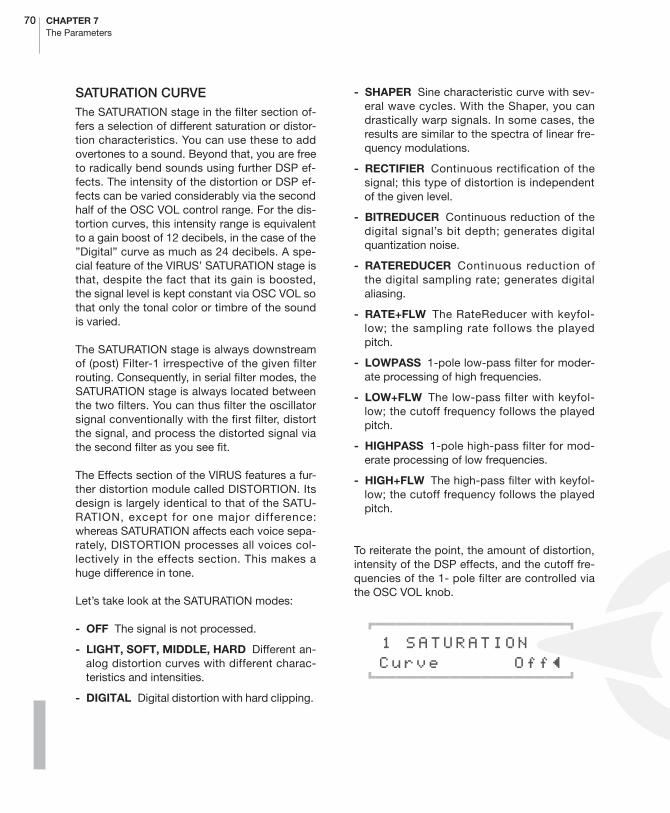
70 CHAPTER 7The Parameters
SATURATION CURVEThe SATURATION stage in the filter section of-fers a selection of different saturation or distor-tion characteristics. You can use these to addovertones to a sound. Beyond that, you are freeto radically bend sounds using further DSP ef-fects. The intensity of the distortion or DSP ef-fects can be varied considerably via the secondhalf of the OSC VOL control range. For the dis-tortion curves, this intensity range is equivalentto a gain boost of 12 decibels, in the case of the”Digital” curve as much as 24 decibels. A spe-cial feature of the VIRUS’ SATURATION stage isthat, despite the fact that its gain is boosted,the signal level is kept constant via OSC VOL sothat only the tonal color or timbre of the soundis varied.
The SATURATION stage is always downstreamof (post) Filter-1 irrespective of the given filterrouting. Consequently, in serial filter modes, theSATURATION stage is always located betweenthe two filters. You can thus filter the oscillatorsignal conventionally with the first filter, distortthe signal, and process the distorted signal viathe second filter as you see fit.
The Effects section of the VIRUS features a fur-ther distortion module called DISTORTION. Itsdesign is largely identical to that of the SATU-RATION, except for one major difference:whereas SATURATION affects each voice sepa-rately, DISTORTION processes all voices col-lectively in the effects section. This makes ahuge difference in tone.
Let’s take look at the SATURATION modes:
- OFF The signal is not processed.
- LIGHT, SOFT, MIDDLE, HARD Different an-alog distortion curves with different charac-teristics and intensities.
- DIGITAL Digital distortion with hard clipping.
- SHAPER Sine characteristic curve with sev-eral wave cycles. With the Shaper, you candrastically warp signals. In some cases, theresults are similar to the spectra of linear fre-quency modulations.
- RECTIFIER Continuous rectification of thesignal; this type of distortion is independentof the given level.
- BITREDUCER Continuous reduction of thedigital signal’s bit depth; generates digitalquantization noise.
- RATEREDUCER Continuous reduction ofthe digital sampling rate; generates digitalaliasing.
- RATE+FLW The RateReducer with keyfol-low; the sampling rate follows the playedpitch.
- LOWPASS 1-pole low-pass filter for moder-ate processing of high frequencies.
- LOW+FLW The low-pass filter with keyfol-low; the cutoff frequency follows the playedpitch.
- HIGHPASS 1-pole high-pass filter for mod-erate processing of low frequencies.
- HIGH+FLW The high-pass filter with keyfol-low; the cutoff frequency follows the playedpitch.
To reiterate the point, the amount of distortion,intensity of the DSP effects, and the cutoff fre-quencies of the 1- pole filter are controlled viathe OSC VOL knob.
01111111111111111112
1 SATURATION Curve Off≤ 61111111111111111154
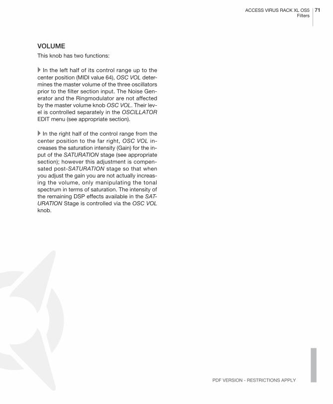
ACCESS VIRUS RACK XL OS5 71Filters
PDF VERSION - RESTRICTIONS APPLY
VOLUMEThis knob has two functions:
� In the left half of its control range up to thecenter position (MIDI value 64), OSC VOL deter-mines the master volume of the three oscillatorsprior to the filter section input. The Noise Gen-erator and the Ringmodulator are not affectedby the master volume knob OSC VOL. Their lev-el is controlled separately in the OSCILLATOREDIT menu (see appropriate section).
� In the right half of the control range from thecenter position to the far right, OSC VOL in-creases the saturation intensity (Gain) for the in-put of the SATURATION stage (see appropriatesection); however this adjustment is compen-sated post-SATURATION stage so that whenyou adjust the gain you are not actually increas-ing the volume, only manipulating the tonalspectrum in terms of saturation. The intensity ofthe remaining DSP effects available in the SAT-URATION Stage is controlled via the OSC VOLknob.
72 CHAPTER 7The Parameters
Envelope Section (Encoder)
� FILTER ENVELOPE
ATTACKDetermines the amount of time it takes for thefilter envelope to rise to its maximum level. Thehigher the ATTACK value, the longer it takes forthe envelope to rise to maximum volume afterthe start of a note.
DECAYDetermines the amount of time it takes for thefilter envelope to fade out. The higher the DE-CAY value, the longer it takes for the envelopeto fall from its peak level to the SUSTAIN value.
SUSTAINDetermines a variable level for the filter enve-lope at which it remains after the end of the DE-CAY phase (see appropriate section). Theduration of the SUSTAIN phase depends on theTIME value (see appropriate section).
TIMESets the bipolar time parameter for the filter en-velope. It determines the envelope’s responseonce it reaches the SUSTAIN phase (see appro-priate section): If the knob is set to the center
position (12 o’clock) indicated by the mathe-matical infinity symbol, then the SUSTAIN levelremains constant through to the end of thenote; if you turn it counter-clockwise to the left(towards FALL), then the level drops off at an in-creasing rate towards the minimum level; If youturn the knob clockwise to the right (towardsRISE), the level rises at an increasing rate tomaximum.
RELEASE
Determines the speed or rate at which the vol-ume of the filter envelope decreases after theend of a note. The higher the DECAY value, thelonger it takes for the envelope to fall from itscurrent level to the minimum level, when the keyis released.
� AMPLIFIER ENVELOPE
ATTACKDetermines the amount of time it takes for theamplifier envelope to rise to its maximum level.The higher the ATTACK value, the longer ittakes for the envelope to rise to maximum vol-ume after the start of a note.
DECAYDetermines the amount of time it takes for theamplifier envelope to fade out. The higher theDECAY value, the longer it takes for the enve-lope to fall from its peak level to the SUSTAINvalue.

ACCESS VIRUS RACK XL OS5 73Amplifier Envelope
PDF VERSION - RESTRICTIONS APPLY
SUSTAINSets a variable level value for the amplifier en-velope at which it remains after the end of theDECAY phase (see appropriate section). Theduration of the SUSTAIN phase depends on theTIME value (see appropriate section).
TIMESets the bipolar time parameter for the amplifierenvelope. It determines the envelope’s re-sponse once it reaches the SUSTAIN level (seeappropriate section): If the knob is set to thecenter position (12 o’clock) indicated by themathematical infinity symbol, then the SUSTAINlevel remains constant through to the end of the
note; if you turn it counter-clockwise to the left(towards FALL), then the level drops off at an in-creasing rate towards the minimum level; If youturn the knob clockwise to the right (towardsRISE), the level rises at an increasing rate tomaximum.
RELEASEDetermines the speed or rate at which the vol-ume of the amplifier envelope decreases afterthe end of a note. The higher the RELEASE val-ue, the longer it takes for the envelope to fallfrom its current level to the minimum level,when the key is released.

74 CHAPTER 7The Parameters
LFO Section (Encoder)
� LFO 1
RATEDetermines the speed or rate of the LFO. In pol-yphonic sounds, the manually selected RATEvalue deviates slightly from voice to voice to liv-en up the sound of the LFOs, which also oscil-late polyphonically. When the LFO is synced upto the master clock, the desired note value isselected via the RATE knob.
If LFO clock is set to anything but OFF, the rateknob will choose the clock.
SHAPEDetermines the waveshape of the LFO. You canselect from a sine, triangle, sawtooth, pulsewave, a stepped random modulation (S&H;short for Sample & Hold) or a smooth randommodulation (S&G; short for Sample & Glide). Al-ternatively choose from a selection of 64 staticwaveforms (WAVE 1-64)
CONTOURBy LFO Contour you can now bend or ”morph”(almost) all the LFO waveforms. A brief surveyof the LFO Contour options for the differentLFO modes follows:
01111111111111111112
1 LFO 1 Contour +0≤61111111111111111154
- SINE Contour morphs from sine to a trianglewave (Contour to the left) or to a square wave(Contour to the right).
- TRIANGLE Contour morphs from a triangleto a declining (Contour to the left) or ascend-ing sawtooth (Contour to the right).
- SAWTOOTH Contour morphs from a lineardeclining sawtooth or decay to any exponen-tially declining decay(Contour to the left) or toa square (Contour to the right).
- SQUARE Contour modulates the pulsewidth of the square wave.
KEY FOLLOWControls the intensity of the KEY FOLLOWfunction - i.e. the rate at which the LFO followsthe pitch of a played note. At a value of 0, KEYFOLLOW is deactivated. At a value of 127, therate doubles with each octave.
01111111111111111112
1 LFO1 Keyfollow Off≤61111111111111111154
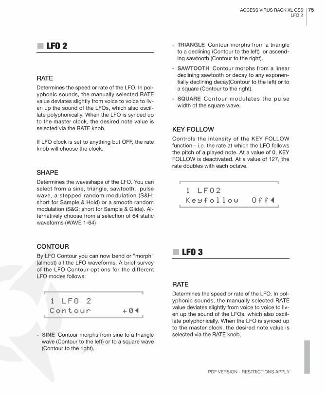
ACCESS VIRUS RACK XL OS5 75LFO 2
PDF VERSION - RESTRICTIONS APPLY
� LFO 2
RATEDetermines the speed or rate of the LFO. In pol-yphonic sounds, the manually selected RATEvalue deviates slightly from voice to voice to liv-en up the sound of the LFOs, which also oscil-late polyphonically. When the LFO is synced upto the master clock, the desired note value isselected via the RATE knob.
If LFO clock is set to anything but OFF, the rateknob will choose the clock.
SHAPEDetermines the waveshape of the LFO. You canselect from a sine, triangle, sawtooth, pulsewave, a stepped random modulation (S&H;short for Sample & Hold) or a smooth randommodulation (S&G; short for Sample & Glide). Al-ternatively choose from a selection of 64 staticwaveforms (WAVE 1-64)
CONTOURBy LFO Contour you can now bend or ”morph”(almost) all the LFO waveforms. A brief surveyof the LFO Contour options for the differentLFO modes follows:
01111111111111111112
1 LFO 2 Contour +0≤61111111111111111154
- SINE Contour morphs from sine to a trianglewave (Contour to the left) or to a square wave(Contour to the right).
- TRIANGLE Contour morphs from a triangleto a declining (Contour to the left) or ascend-ing sawtooth (Contour to the right).
- SAWTOOTH Contour morphs from a lineardeclining sawtooth or decay to any exponen-tially declining decay(Contour to the left) or toa square (Contour to the right).
- SQUARE Contour modulates the pulsewidth of the square wave.
KEY FOLLOWControls the intensity of the KEY FOLLOWfunction - i.e. the rate at which the LFO followsthe pitch of a played note. At a value of 0, KEYFOLLOW is deactivated. At a value of 127, therate doubles with each octave.
01111111111111111112
1 LFO2 Keyfollow Off≤61111111111111111154
� LFO 3
RATEDetermines the speed or rate of the LFO. In pol-yphonic sounds, the manually selected RATEvalue deviates slightly from voice to voice to liv-en up the sound of the LFOs, which also oscil-late polyphonically. When the LFO is synced upto the master clock, the desired note value isselected via the RATE knob.
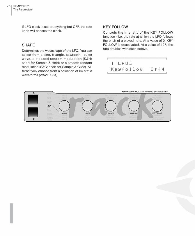
76 CHAPTER 7The Parameters
If LFO clock is set to anything but OFF, the rateknob will choose the clock.
SHAPEDetermines the waveshape of the LFO. You canselect from a sine, triangle, sawtooth, pulsewave, a stepped random modulation (S&H;short for Sample & Hold) or a smooth randommodulation (S&G; short for Sample & Glide). Al-ternatively choose from a selection of 64 staticwaveforms (WAVE 1-64)
KEY FOLLOWControls the intensity of the KEY FOLLOWfunction - i.e. the rate at which the LFO followsthe pitch of a played note. At a value of 0, KEYFOLLOW is deactivated. At a value of 127, therate doubles with each octave.
01111111111111111112
1 LFO3 Keyfollow Off≤61111111111111111154
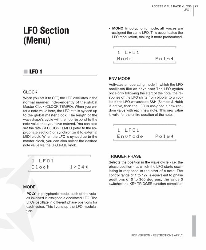
ACCESS VIRUS RACK XL OS5 77LFO 1
PDF VERSION - RESTRICTIONS APPLY
LFO Section (Menu)
� LFO 1
CLOCKWhen you set it to OFF, the LFO oscillates in thenormal manner, independently of the globalMaster Clock (CLOCK TEMPO). When you en-ter a note value here, the LFO rate is synced upto the global master clock. The length of thewaveshape’s cycle will then correspond to thenote value that you have entered. You can alsoset the rate via CLOCK TEMPO (refer to the ap-propriate section) or synchronize it to externalMIDI clock. When the LFO is synced up to themaster clock, you can also select the desirednote value via the LFO RATE knob.
01111111111111111112
1 LFO1 Clock 1/24≤61111111111111111154
MODE
- POLY In polyphonic mode, each of the voic-es involved is assigned a dedicated LFO. TheLFOs oscillate in different phase positions foreach voice. This livens up the LFO modula-tion.
- MONO In polyphonic mode, all voices areassigned the same LFO. This accentuates theLFO modulation, making it more pronounced.
01111111111111111112
1 LFO1 Mode Poly≤61111111111111111154
ENV MODEActivates an operating mode in which the LFOoscillates like an envelope: The LFO cyclesonce only following the start of the note; the re-sponse of the LFO shifts from bipolar to unipo-lar. If the LFO waveshape S&H (Sample & Hold)is active, then the LFO is assigned a new ran-dom value with each new note. This new valueis valid for the entire duration of the note.
01111111111111111112
1 LFO1 EnvMode Poly≤61111111111111111154
TRIGGER PHASESelects the position in the wave cycle - i.e. thephase position - at which the LFO starts oscil-lating in response to the start of a note. Thecontrol range of 1 to 127 is equivalent to phasepositions of 0 to 360 degrees; the value 0switches the KEY TRIGGER function complete-
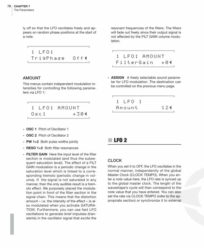
78 CHAPTER 7The Parameters
ly off so that the LFO oscillates freely and ap-pears on random phase positions at the start ofa note.
01111111111111111112
1 LFO1 TrigPhase Off≤61111111111111111154
AMOUNT This menus contain independent modulation in-tensities for controlling the following parame-ters via LFO 1:
01111111111111111112
1 LFO1 AMOUNT Osc1 +30≤61111111111111111154
- OSC 1 Pitch of Oscillator 1
- OSC 2 Pitch of Oscillator 2
- PW 1+2 Both pulse widths jointly
- RESO 1+2 Both filter resonances
- FILTER GAIN Here the input level of the filtersection is modulated (and thus the subse-quent saturation level). The effect of a FILTGAIN modulation is a periodic change in thesaturation level which is linked to a corre-sponding tremolo (periodic change in vol-ume). If the signal is not saturated in anymanner, then the only audible result is a trem-olo effect. We purposely placed the modula-tion point in front of the filter section in thesignal chain. This means that the distortionamount – i.e. the intensity of the effect – is al-so modulated when you activate SATURA-TION. Furthermore, you can use fast LFOoscillations to generate brief impulses (tran-sients) in the oscillator signal that excite the
resonant frequencies of the filters. The filterswill fade out freely since their output signal isnot affected by the FILT GAIN volume modu-lation.
01111111111111111112
1 LFO1 AMOUNT FilterGain +0≤61111111111111111154
- ASSIGN A freely selectable sound parame-ter for LFO modulation. The destination canbe controlled on the previous menu page.
01111111111111111112
1 LFO 1 Amount 12≤61111111111111111154
� LFO 2
CLOCKWhen you set it to OFF, the LFO oscillates in thenormal manner, independently of the globalMaster Clock (CLOCK TEMPO). When you en-ter a note value here, the LFO rate is synced upto the global master clock. The length of thewaveshape’s cycle will then correspond to thenote value that you have entered. You can alsoset the rate via CLOCK TEMPO (refer to the ap-propriate section) or synchronize it to external

ACCESS VIRUS RACK XL OS5 79LFO 2
PDF VERSION - RESTRICTIONS APPLY
MIDI clock. When the LFO is synced up to themaster clock, you can also select the desirednote value via the LFO RATE knob.
01111111111111111112
1 LFO2 Clock 1/24≤61111111111111111154
MODE
- POLY In polyphonic mode, each of the voic-es involved is assigned a dedicated LFO. TheLFOs oscillate in different phase positions foreach voice. This livens up the LFO modula-tion.
- MONO In polyphonic mode, all voices areassigned the same LFO. This accentuates theLFO modulation, making it more pronounced.
01111111111111111112
1 LFO2 Mode Poly≤61111111111111111154
ENV MODEActivates an operating mode in which the LFOoscillates like an envelope: The LFO cyclesonce only following the start of the note; the re-sponse of the LFO shifts from bipolar to unipo-lar. If the LFO waveshape S&H (Sample & Hold)is active, then the LFO is assigned a new ran-dom value with each new note. This new valueis valid for the entire duration of the note.
01111111111111111112
1 LFO2 EnvMode Poly≤61111111111111111154
TRIGGER PHASESelects the position in the wave cycle - i.e. thephase position - at which the LFO starts oscil-lating in response to the start of a note. Thecontrol range of 1 to 127 is equivalent to phasepositions of 0 to 360 degrees; the value 0switches the KEY TRIGGER function complete-ly off so that the LFO oscillates freely and ap-pears on random phase positions at the start ofa note.
01111111111111111112
1 LFO2 TrigPhase Off≤61111111111111111154
AMOUNT
This menus contain independent modulationintensities for controlling the following param-eters via LFO 2:
01111111111111111112
1 LFO2 AMOUNT Shape 1+2 +0≤61111111111111111154
- SHAPE 1+2 The SHAPE parameters of bothoscillators jointly
- FILTER 1 The frequency of the first filter
- FILTER 2 The frequency of the second filter
- PAN Panorama position
- FM AMOUNT FM Amount. An additionalmodulation destination of LFO-2. The intensi-ty of the frequency modulation of Oscillator 2is modulated.

80 CHAPTER 7The Parameters
- ASSIGN A freely selectable sound parame-ter for LFO modulation. The destination canbe controlled on the previous menu page.
01111111111111111112
1 LFO 1 Amount 12≤61111111111111111154
� LFO 3
CLOCKWhen you set it to OFF, the LFO oscillates in thenormal manner, independently of the globalMaster Clock (CLOCK TEMPO). When you en-ter a note value here, the LFO rate is synced upto the global master clock. The length of thewaveshape’s cycle will then correspond to thenote value that you have entered. You can alsoset the rate via CLOCK TEMPO (refer to the ap-propriate section) or synchronize it to externalMIDI clock. When the LFO is synced up to themaster clock, you can also select the desirednote value via the LFO RATE knob.
01111111111111111112
1 LFO3 Clock 1/24≤61111111111111111154
MODE
- POLY In polyphonic mode, each of the voic-es involved is assigned a dedicated LFO. TheLFOs oscillate in different phase positions foreach voice. This livens up the LFO modula-tion.
- MONO In polyphonic mode, all voices areassigned the same LFO. This accentuates theLFO modulation, making it more pronounced.
01111111111111111112
1 LFO3 Mode Poly≤61111111111111111154
ENV MODEActivates an operating mode in which the LFOoscillates like an envelope: The LFO cyclesonce only following the start of the note; the re-sponse of the LFO shifts from bipolar to unipo-lar. If the LFO waveshape S&H (Sample & Hold)is active, then the LFO is assigned a new ran-dom value with each new note. This new valueis valid for the entire duration of the note.
01111111111111111112
1 LFO3 EnvMode Poly≤61111111111111111154
DESTINATIONDetermines the modulation destination of theLFO. You can select from:
- OSC 1 The pitch of Oscillator 1
- OSC 1+2 The pitch of both oscillators
- OSC 2 The pitch of Oscillator 2
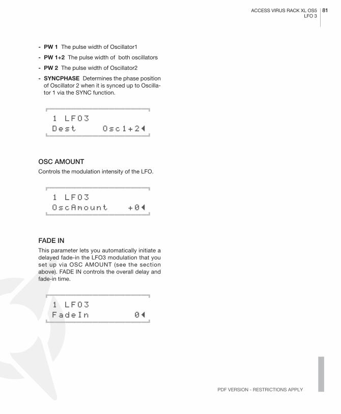
ACCESS VIRUS RACK XL OS5 81LFO 3
PDF VERSION - RESTRICTIONS APPLY
- PW 1 The pulse width of Oscillator1
- PW 1+2 The pulse width of both oscillators
- PW 2 The pulse width of Oscillator2
- SYNCPHASE Determines the phase positionof Oscillator 2 when it is synced up to Oscilla-tor 1 via the SYNC function.
01111111111111111112
1 LFO3 Dest Osc1+2≤61111111111111111154
OSC AMOUNTControls the modulation intensity of the LFO.
01111111111111111112
1 LFO3 OscAmount +0≤61111111111111111154
FADE INThis parameter lets you automatically initiate adelayed fade-in the LFO3 modulation that youset up via OSC AMOUNT (see the sectionabove). FADE IN controls the overall delay andfade-in time.
01111111111111111112
1 LFO3 FadeIn 0≤61111111111111111154

82 CHAPTER 7The Parameters
EFX Section (Encoder)
The Effects menu contains the parameters ofthe effects section and audio inputs (INPUT).The following effects are available individuallyper PART and in stereo:
The vocoder and the delay/reverb section areeach available just once, but they can be ad-dressed individually by the PARTs. In the sig-nal path, all effects are connected in series inaccordance with sequence in the Effectsmenu.
� REVERB
The following parameters are only availablewhen you’re working with REVERB algorithms.
REVERB DECAY TIMEThis parameter determines the decay time forthe given room.
In a real room, the sound bounces off severalwalls and covers a considerable distance be-fore it reaches your ear. The longer the soundtravels and the more often it is reflected, thesofter it will become. You could say that this ef-fect is comparable to a pool or billiards ball thattravels a greater distance, bouncing of severalcushioned edges along the way. This frictiondepletes energy and causes the pool ball toslow down. The sound’s loss of energy is con-trolled via DECAY TIME. When you dial in theminimum value, the decay time is extremelyshort so you’ll hear just the early reflections. Atthe peak value, no energy is lost so the decaytime is infinite, which is of course physically im-possible in the real world.
01111111111111111112
1 REVERB DecayTime 16≤61111111111111111154
REVERB DAMPINGThis parameter controls high-frequency attenu-ation of the room’s fading reflections.
In a real room, walls don’t reflect high frequen-cies as well as they do lower frequencies, an ef-fect that can be likened to natural low-passfiltering of the sound. The longer the soundtravels, the more often it bounces off walls andthe more intense this filtering effect. For thisreason, the amount of high-end damping de-pends on the amount of time that the signalcarries - the signal thrown back by the room be-comes muddier as time goes by. This effect isstronger with walls that have soft surfaces(wood, wallpaper) than it is with walls that have
RINGMODULATOR
DISTORTION
ANALOG BOOST
PHASER
CHORUS
EQUALIZER

ACCESS VIRUS RACK XL OS5 83Reverb
PDF VERSION - RESTRICTIONS APPLY
hard surfaces (glass, tiles). Consequently, high-end damping has a significant influence thevibe and warmth of the room sound.
01111111111111111112
1 REVERB Damping 12≤61111111111111111154
REVERB PREDELAYThis parameter controls the pre-delay time ofthe given room simulation.In a real room, sound travels quite a distanceand is reflected at least once before it reachesyour ear. This means that a certain amount oftime elapses before you hear the earliest reflec-tions of the room signal. The bigger the room,the longer it takes for the reflected signal toreach your ear. This effect is emulated in a roomsimulation be means of a parameter called pre-delay. Irrespective of the values set for the otherREVERB parameters, the amount of pre-delayhas a decisive impact on our perception of thesize of a room.
When you set a high pre-delay value - say somehundred milliseconds - you’re actually creatingan “unnaturally” large room. The room simula-tion will sound washed out or much like a dif-fuse echo. Pre-delay has a formative effect onroom simulation, particularly since - like withthe pure DELAY algorithms - you can use it tomatch the reverb effect to the rhythmic context.And like the DELAY parameters, pre-delay is in-finitely variable, it is suitable for generatingfeedback, and it can be synced up to the globalclock generator.
REVERB PREDELAY controls the absolute pre-delay time in milliseconds (ms). The peak valuedepends on the room size (REVERB TYPE, seeabove) that you have selected because theroom simulation and pre-delay share the same
memory. Pre-delay time is infinitely variable.Changing the delay time bends the pitch of thereverb signal. REVERB PREDELAY will not ap-pear in the display when the pre-delay amountis determined via REVERB CLOCK (see below).
01111111111111111112
1 REVERB PreDelay 500.0≤61111111111111111154
REVERB FEEDBACKAvailable exclusively for the Rev+Feedb1 andRev+Feedb2 algorithms, this parameter con-trols the amount of pre-delay feedback. Herethe room signal is repeated at intervals that aredetermined by the pre-delay time. Note that thesignal level fades gradually. REVERB COLORalso has an influence on feedback. The intensityof the filtering effect generated by the low-passor high-pass filter increases with every repeti-tion. Feedback is subtle when the decay time ofthe room (REVERB DECAY TIME) is long. Theeffect will become more prominent when youset a short decay time and a long pre-delaytime.
01111111111111111112
1 REVERB Feedback 50≤61111111111111111154
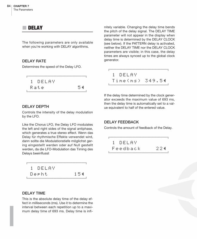
84 CHAPTER 7The Parameters
� DELAY
The following parameters are only availablewhen you’re working with DELAY algorithms.
DELAY RATEDetermines the speed of the Delay LFO.
01111111111111111112
1 DELAY Rate 5≤61111111111111111154
DELAY DEPTHControls the intensity of the delay modulationby the LFO.
Like the Chorus LFO, the Delay LFO modulatesthe left and right sides of the signal antiphase,which generates a true stereo effect. Wenn dasDelay für rhythmische Effekte verwendet wird,dann sollte die Modulationstiefe möglichst ger-ing eingestellt werden oder auf Null gestelltwerden, da die LFO-Modulation das Timing desDelays beeinflusst
01111111111111111112
1 DELAY Depht 15≤61111111111111111154
DELAY TIMEThis is the absolute delay time of the delay ef-fect in milliseconds (ms). Use it to determine theinterval between each repetition up to a maxi-mum delay time of 693 ms. Delay time is infi-
nitely variable. Changing the delay time bendsthe pitch of the delay signal. The DELAY TIMEparameter will not appear in the display whendelay time is determined by the DELAY CLOCK(see below). If the PATTERN delay is activated,neither the DELAY TIME nor the DELAY CLOCKparameters are visible; in this case, the delaytimes are always synced up to the global clockgenerator.
01111111111111111112
1 DELAY Time(ms) 349.5≤61111111111111111154
If the delay time determined by the clock gener-ator exceeds the maximum value of 693 ms,then the delay time is automatically set to a val-ue equivalent to half of the entered value.
DELAY FEEDBACKControls the amount of feedback of the Delay.
01111111111111111112
1 DELAY Feedback 22≤61111111111111111154
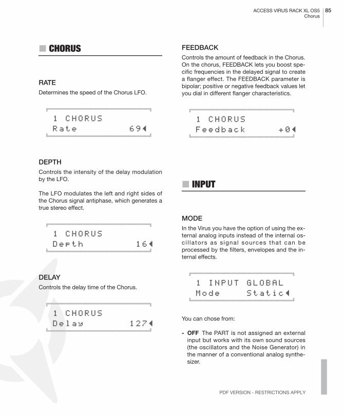
ACCESS VIRUS RACK XL OS5 85Chorus
PDF VERSION - RESTRICTIONS APPLY
� CHORUS
RATEDetermines the speed of the Chorus LFO.
01111111111111111112
1 CHORUS Rate 69≤61111111111111111154
DEPTHControls the intensity of the delay modulationby the LFO.
The LFO modulates the left and right sides ofthe Chorus signal antiphase, which generates atrue stereo effect.
01111111111111111112
1 CHORUS Depth 16≤61111111111111111154
DELAYControls the delay time of the Chorus.
01111111111111111112
1 CHORUS Delay 127≤61111111111111111154
FEEDBACKControls the amount of feedback in the Chorus.On the chorus, FEEDBACK lets you boost spe-cific frequencies in the delayed signal to createa flanger effect. The FEEDBACK parameter isbipolar; positive or negative feedback values letyou dial in different flanger characteristics.
01111111111111111112
1 CHORUS Feedback +0≤61111111111111111154
� INPUT
MODEIn the Virus you have the option of using the ex-ternal analog inputs instead of the internal os-c i l la tors as s igna l sources that can beprocessed by the filters, envelopes and the in-ternal effects.
01111111111111111112
1 INPUT GLOBAL Mode Static≤61111111111111111154
You can chose from:
- OFF The PART is not assigned an externalinput but works with its own sound sources(the oscillators and the Noise Generator) inthe manner of a conventional analog synthe-sizer.

86 CHAPTER 7The Parameters
- DYNAMIC Instead of the internal soundsources, an external signal source is routed tothe filter section. The envelopes remainfunctional so you have to play notes in orderto hear the external signal source. For in-stance in this mode you can manipulate thevolume to “chop up” the input signal muchthe way a gate does. If you turn FILTER KEYFOLLOW up, the input signal is filtered by adifferent filter frequency depending on thekey you press. The sound program can stillbe played polyphonically and you can alloca-te several different filter frequencies and inde-pendent envelopes simultaneously (!) to theinput signal via the keyboard.
- STATIC Instead of the internal sound sourc-es, an external signal source is routed to thefilter section. In contrast to DYNAMIC mode,in STATIC mode one or two voices (depend-ing on the INPUT SELECT setting, see appro-priate section) of the Virus are activatedautomatically without you actually playingnotes on this PART. The filters and the ampli-fier are switched permanently open, the enve-lopes are deactivated and incoming notes areignored. Consequently you can use the filtersand the amplifier as an effects section for theinput signal.
INPUT SELECTSelects the external signal source for the INPUTMODEs.
The signal source that you select here is usedalso for the vocoder.
01111111111111111112
1 INPUT Select In L+R≤61111111111111111154
If the selected signal source is a stereo source -i.e. IN L+R, - then the sound program is auto-matically switched internally to UNISON-MODE= Twin, regardless of the UNISON MODE pa-rameter setting so that the input signal is proc-essed in stereo. In this case, the UNISONparameters PAN SPREAD and LFO PHASE (seeappropriate section) are active
Several PARTs can simultaneously access theexternal input via INPUT SELECT.
Input Meaning
- IN L The left channel of the ex-ternal dual audio input.
- IN L+R Both channels of the ex-ternal dual audio input(stereo).
- IN R The right channel of theexternal dual audio input.
- AUX 1 L The left channel of internalAux 1.
- AUX 1 L+R Both channels of internalAux 1 (stereo).
- AUX 1 R The right channel of inter-nal Aux 1.
- AUX 2 L The left channel of internalAux 2.
- AUX 2 L+R Both channels of internalAux 2 (stereo).
- AUX 2 R The right channel of inter-nal Aux 2.
Input Meaning

ACCESS VIRUS RACK XL OS5 87Analog Boost
PDF VERSION - RESTRICTIONS APPLY
� ANALOG BOOST
This effect produces the typical bass punch onanalog synthesizers, and with the correspond-ing TUNE setting you can emphasis the punchin the mid frequencies or even lower the treblefrequencies. In its mild form ANALOG BOOST issuitable for almost all sounds, collaborates wellwith the distortion section, and if necessary canbe set to extreme values.
INTENSITY
Controls the amount of ANALOG BOOST.
01111111111111111112
1 ANALOG BOOST Intensity 17≤61111111111111111154
TUNEControls the frequency range of ANALOGBOOST.
01111111111111111112
1 ANALOG BOOST Tune 32≤61111111111111111154
88 CHAPTER 7The Parameters
EFX Section/Menu
� DELAY/REVERB
As its name would indicate, the DELAY/RE-VERB section generates two different effects:
The DELAY effect does just that to the input sig-nal – delay it to create echoes. Much like a cho-rus, you can modulate the delay time to createoscillations and phase shifting in the stereopanorama. Delay time can also be locked intosync with the global clock generator. As a re-sult, the rhythm of the repetitions can bematched up to the given song tempo. Beyondthat, the device offers diverse delay pattern al-gorithms where the left and right signals are de-layed so that echoes are repeated in differentbeats. By varying FEEDBACK values, you cancome up with interesting rhythmic patterns.
The REVERB effect, on the other hand, simu-lates the reflections that occur in “natural”rooms. This particular effect features severalparameters that let you come up with effectsthat go beyond simple room simulation. For ex-ample, you can use the DELAY unit describedabove to dial in the desired pre-delay for roomsimulations. The DELAY effect is located priorto the room simulation in the signal path. Delaytime and feedback are infinitely variable andmay be synced up to the global clock genera-tor. This means that you can create REVERB ef-fects that are a perfect match for the rhythmiccontext.
In PARAMETER mode, you can select variousDELAY and REVERB algorithms. Some of theREVERB algorithms work with parameters thatthe DELAY algorithms do not use and vice ver-sa, so we’ll look at these special parameters ina separate section.
In SINGLE MODE, all Delay or Reverb settingsapply to the SINGLE PROGRAM in the conven-tional manner and are stored along with theprogram.
However in MULTI MODE, all 16 PARTs accessthe same Delay or Reverb effect. In this case,the only dedicated parameter you have availa-ble for each part is EFFECT SEND; all other pa-rameters apply to the same Delay/Reverb unitand affect all PARTs.
Consequently, if you set the Virus to MULTIMODE or MULTI SINGLE MODE, all settingsyou dial in for the Delay or Reverb (includingEFFECT SEND) affect the MULTI PROGRAMand are stored along with it. If the Virus is inMULTI MODE or MULTI SINGLE MODE and youactivate a new SINGLE, the Delay/Reverb pa-rameters of the SINGLE are ignored and the De-lay/Reverb parameters of the current MULTIPROGRAM are activate.
As a rule, in MULTI MODE all SINGLE settingspertaining to the Delay/Reverb are ignored,with the exception of EFFECT SEND.
EFFECT SENDThe level at which the given sound is patched tothe DELAY or REVERB effect is adjusted here.
EFFECT SEND is identical to a post-fader effectbus on a mixing console. When you move thecontrol toward the end of its control range, thedry signal is faded out and only the wet DELAY/REVERB signal is audible.
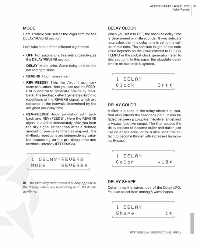
ACCESS VIRUS RACK XL OS5 89Delay/Reverb
PDF VERSION - RESTRICTIONS APPLY
MODEHere’s where you select the algorithm for theDELAY/REVERB section.
Let’s take a tour of the different algorithms:
- OFF Not surprisingly, this setting deactivatesthe DELAY/REVERB section.
- DELAY Mono echo. Same delay time on theleft and right sides.
- REVERB Room simulation.
- REV+FEEDB1 This the Virus' trademarkroom simulation. Here you can use the FEED-BACK control to generate pre-delay feed-back. The feedback effect generates rhythmicrepetitions of the REVERB signal, which arerepeated at the intervals determined by theassigned pre-delay time.
- REV+FEEDB2 Room simulation with feed-back and REV+FEEDB1. Here the REVERBsignal is audible immediately after you hearthe dry signal rather than after a definedamount of pre-delay time has elapsed. Therhythmic repetitions are independently varia-ble depending on the pre-delay time andfeedback intensity (FEEDBACK).
01111111111111111112
1 DELAY/REVERB MODE REVERB≤61111111111111111154
� The following parameters will only appear inthe display when you’re working with DELAY al-gorithms.
DELAY CLOCKWhen you set it to OFF, the absolute delay timeis determined in milliseconds. If you select anote value, then the delay time is set to the val-ue of this note. The absolute length of this notevalue depends on the value entered to CLOCKTEMPO in the global clock generator (refer tothis section). In this case, the absolute delaytime in milliseconds is ignored.
01111111111111111112
1 DELAY Clock Off≤61111111111111111154
DELAY COLORA filter is placed in the delay effect's output,that also effects the feedback path. It can befaded between a Lowpass (negative range) anda Hipass (positive range). The filter causes thedelay repeats to become duller and duller, justlike on a tape echo, or for a nice unnatural ef-fect, to become thinner with increased harmon-ics (Hipass).
01111111111111111112
1 DELAY Color +10≤61111111111111111154
DELAY SHAPEDetermines the waveshape of the Delay LFO.You can select from among 6 waveshapes.
01111111111111111112
1 DELAY Shape 1≤61111111111111111154
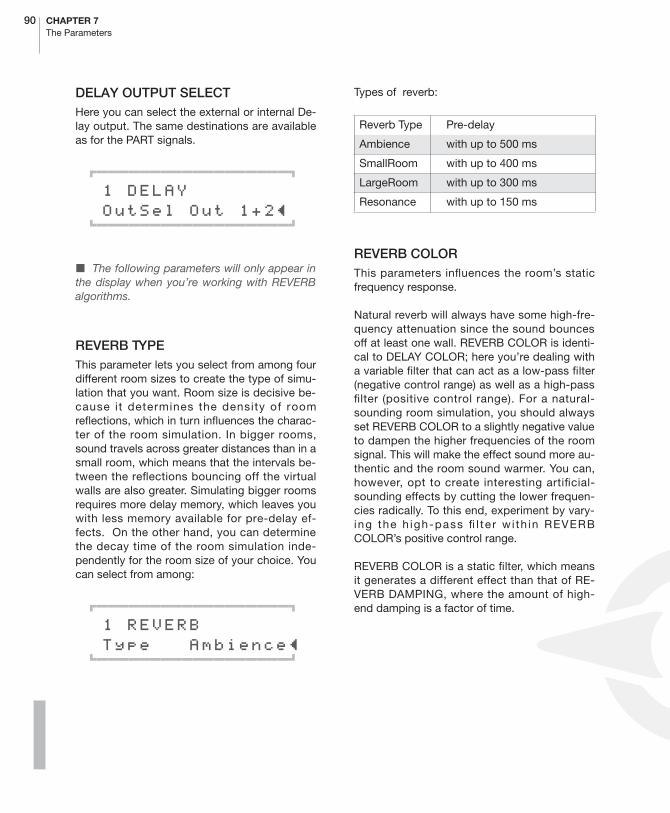
90 CHAPTER 7The Parameters
DELAY OUTPUT SELECTHere you can select the external or internal De-lay output. The same destinations are availableas for the PART signals.
01111111111111111112
1 DELAY OutSel Out 1+2≤61111111111111111154
� The following parameters will only appear inthe display when you’re working with REVERBalgorithms.
REVERB TYPEThis parameter lets you select from among fourdifferent room sizes to create the type of simu-lation that you want. Room size is decisive be-cause it determines the density of roomreflections, which in turn influences the charac-ter of the room simulation. In bigger rooms,sound travels across greater distances than in asmall room, which means that the intervals be-tween the reflections bouncing off the virtualwalls are also greater. Simulating bigger roomsrequires more delay memory, which leaves youwith less memory available for pre-delay ef-fects. On the other hand, you can determinethe decay time of the room simulation inde-pendently for the room size of your choice. Youcan select from among:
01111111111111111112
1 REVERB Type Ambience≤61111111111111111154
Types of reverb:
REVERB COLORThis parameters influences the room’s staticfrequency response.
Natural reverb will always have some high-fre-quency attenuation since the sound bouncesoff at least one wall. REVERB COLOR is identi-cal to DELAY COLOR; here you’re dealing witha variable filter that can act as a low-pass filter(negative control range) as well as a high-passfilter (positive control range). For a natural-sounding room simulation, you should alwaysset REVERB COLOR to a slightly negative valueto dampen the higher frequencies of the roomsignal. This will make the effect sound more au-thentic and the room sound warmer. You can,however, opt to create interesting artificial-sounding effects by cutting the lower frequen-cies radically. To this end, experiment by vary-ing the h igh-pass fi l ter wi th in REVERBCOLOR’s positive control range.
REVERB COLOR is a static filter, which meansit generates a different effect than that of RE-VERB DAMPING, where the amount of high-end damping is a factor of time.
Reverb Type Pre-delay
Ambience with up to 500 ms
SmallRoom with up to 400 ms
LargeRoom with up to 300 ms
Resonance with up to 150 ms
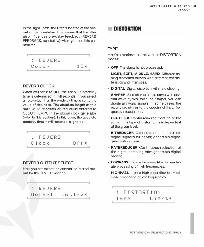
ACCESS VIRUS RACK XL OS5 91Distortion
PDF VERSION - RESTRICTIONS APPLY
In the signal path. the filter is located at the out-put of the pre-delay. This means that the filteralso influences pre-delay feedback (REVERBFEEDBACK, see below) when you use this pa-rameter.
01111111111111111112
1 REVERB Color -10≤61111111111111111154
REVERB CLOCKWhen you set it to OFF, the absolute predelaytime is determined in milliseconds. If you selecta note value, then the predelay time is set to thevalue of this note. The absolute length of thisnote value depends on the value entered toCLOCK TEMPO in the global clock generator(refer to this section). In this case, the absolutepredelay time in milliseconds is ignored.
01111111111111111112
1 REVERB Clock Off≤61111111111111111154
REVERB OUTPUT SELECTHere you can select the external or internal out-put for the REVERB section.
01111111111111111112
1 REVERB OutSel Out1+2≤61111111111111111154
� DISTORTION
TYPEHere’s a rundown on the various DISTORTIONmodes:
- OFF The signal is not processed.
- LIGHT, SOFT, MIDDLE, HARD Different an-alog distortion curves with different charac-teristics and intensities.
- DIGITAL Digital distortion with hard clipping.
- SHAPER Sine characteristic curve with sev-eral wave cycles. With the Shaper, you candrastically warp signals. In some cases, theresults are similar to the spectra of linear fre-quency modulations.
- RECTIFIER Continuous rectification of thesignal; this type of distortion is independentof the given level.
- BITREDUCER Continuous reduction of thedigital signal’s bit depth; generates digitalquantization noise.
- RATEREDUCER Continuous reduction ofthe digital sampling rate; generates digitalaliasing.
- LOWPASS 1-pole low-pass filter for moder-ate processing of high frequencies.
- HIGHPASS 1-pole high-pass filter for mod-erate processing of low frequencies.
01111111111111111112
1 DISTORTION Type Light≤61111111111111111154

92 CHAPTER 7The Parameters
INTENSITYFor the distortion curves, this intensity range isequivalent to a gain boost of 12 decibels, in thecase of the ”Digital” curve as much as 24 deci-bels. A special feature of the VIRUS’ SATURA-TION stage is that, despite the fact that its gainis boosted, the signal level is kept constant sothat only the tonal color or timbre of the soundis varied.
The Effects section of the VIRUS features a fur-ther distortion module called SATURATION. Itsdesign is identical to that of the DISTORTIONmodule discussed here, except for one majordifference: whereas SATURATION affects eachvoice separately, DISTORTION processes allvoices collectively in the effects section. Thismakes a huge difference in tone.
� PHASER
DIR/EFFControls the balance of volume levels betweenthe direct signal and the Phaser signal: At a val-ue of 0, only the direct signal is audible, at a val-ue of 127, only the Phaser output signal isaudible. The values between these two ex-tremes determine the mix of the two signals.
The pure phaser signal is generated by frequen-cy-dependent phase shifting (PHASER Fre-quency) and pitch modulation of the phaser’sown LFOs (PHASER Rate and Depth). Not untilthe direct or dry signal (PHASER Dir/Eff) ismixed to the wet effects signal is the typicalphaser effect generated.
DEPTHControls the intensity of the Phaser frequencymodulation by the LFO.
01111111111111111112
1 PHASER Depth 112≤ 61111111111111111154
FREQUENCYThe characteristic corner frequency of thephaser’s all-pass filter. The frequencies of theleft and right sides are shifted every so slightlyto create a real stereo effect.
01111111111111111112
1 PHASER Frequency 48≤ 61111111111111111154
RATEDetermines the speed of the Phaser LFO.
01111111111111111112
1 PHASER Rate 36≤ 61111111111111111154
FEEDBACKControls the amount of feedback in the Phaser.On the phaser, FEEDBACK lets you boost spe-cific frequencies in the phase-shifted signal.

ACCESS VIRUS RACK XL OS5 93Chorus
PDF VERSION - RESTRICTIONS APPLY
The FEEDBACK parameter is bipolar; positiveor negative feedback values let you dial in dif-ferent phaser characteristics.
01111111111111111112
1 PHASER Feedback +0≤ 61111111111111111154
STAGESUse STAGES (1-6) to select the number ofphaser stages or filter poles. This determinesdirectly the number of filter notches and peaksin the phaser signal.
01111111111111111112
1 PHASER Stages 4≤ 61111111111111111154
SPREADUse SPREAD to increase or decrease the dis-tance between the notches and peaks in thefrequency spectrum. In other words, here youcan adjust bandwidth of the phaser effect.
01111111111111111112
1 PHASER Spread 127≤ 61111111111111111154
� CHORUS
DIR/EFFControls the balance of volume levels betweenthe direct signal and the Chorus signal: At a val-ue of 0, only the direct signal is audible, at a val-ue of 127, only the Chorus output signal isaudible. The values between these two ex-tremes determine the mix of the two signals.
The pure chorus signal is created by a delay(CHORUS delay) and a pitch modulation of thechorus’ on-board LFOs (CHORUS Rate andDepth). Not until the direct or dry signal (CHO-RUS Dir/Eff) is mixed to the wet signal is thetypical chorus effect generated.
01111111111111111112
1 CHORUS Dir/Efx 20≤61111111111111111154
SHAPEDetermines the waveshape of the chorus LFO.You can select from among 6 waveshapes.
01111111111111111112
1 CHORUS Shape Triangle≤61111111111111111154
94 CHAPTER 7The Parameters
� EQUALIZER
The equalizer is used for boosting or cuttingbass and/or treble in the signal, as well as forfine adjustment of a definable frequency range(“Mid”). The low and high controls are realizedas single pole shelf filters, whereas the “mid-range” is handled by a two-pole parametricbandpass filter. The equalizer is available seper-ately for each of the 16 sounds in Multi mode.
LOW-EQ GAINLow shelf cut or boost.
LOW-EQ FREQUENCYLow shelf cutoff frequency.
MID-EQ GAINMidrange cut or boost.
MID-EQ FREQUENCYCenter frequency of the midrange bandpass fil-ter. Please note that this can actually be set an-ywhere between 20 Hz and 24 kHz, i.e. it is notnecessarily restricted to what is usually consid-ered “midrange”.
MID-EQ Q-FACTORMidrange bandwidth around the center fre-quency. Lowering the Q-factor increases band-width, so cut or boost will apply to a widerrange of frequencies. Increasing the Q-factornarrows the bandwidth i.e. cut or boost is ap-plied to a narrower range of frequencies. Set-
ting a very high Q-factor (e.g.15) makes thisbandwidth very narrow, allowing for highly se-lective and precise equalization.
HIGH-EQ GAINHigh shelf cut or boost
HIGH-EQ FREQUENCYHigh shelf cutoff frequency.
� VOCODER
VOCODER MODEhere you can enable the vocoder and choosethe signal source for the carrier bank at thesame time:
- OSC This mode uses the whole oscillatorsection of the VIRUS, including the noisegenerator as the carrier signal. The oscillatorscan be played polyphonic which enables theamplifier envelope to work as usual. The dif-ference is in the filter section. The oscillatorsignal does not pass the filter section, as thissection is being used to control the vocoder.It is possible to feed the vocoder with a singlesound which uses the whole filter section.Just use the aux-sends in the multimode tofeed the vocoder’s input with a single soundcreated within another multipart. Use this cer-tain auxiliary send signal as the carrier signalwithin the vocoder.

ACCESS VIRUS RACK XL OS5 95Vocoder
PDF VERSION - RESTRICTIONS APPLY
- OSC-HOLD This sett ing is ident ica l to”OSC” although the hold-mode (which also isavailable at COMMON/KeyMode) is activat-ed.
- NOISE White noise is used as the carrier.The oscillator section is disabled.
- IN (L / In L+R / In R / Aux L ...) The analog in-puts or the aux-sends are the carrier signal. Ifa stereo source, like L+R, is chosen, the leftand right signal is mixed to create a monosignal.
INPUT SELECTWhile INPUT Select regularly assigns the inputsource for INPUT Mode, the modulator bank in-put is assigned here, when the vocoder is acti-vated. Again, stereo sources like L+R are mixedto a monophonic signal.
VOCODER BAND QUANTITYIt is possible to control the number of filterbands here between 1 and 32. This parameterchanges the sonic complexity of the sound, byusing more or less filter bands. Less filter bandsresult in a typical vocoder sound. More filterbands increase the quality of the signal’s repro-duction (e.g. how easily you can ”understand” avocoded voice). The VIRUS’ polyphony mightvary depending on the number of active filterbands.
CENTER FREQUENCYDEFAULT: 64 (MIDDLE)
The central frequency of the bandpass filters inthe modulator- and carrier bank. Using a high Q(filter quality parameter, which is controlled us-ing KEYFOLLOW) you can adjust the centralfrequency of the spectrum you edit.
FREQUENCY SPREADDEFAULT: +63 (RIGHT)
The spread of the filter bands used by the mod-ulator and carrier bank. This parameter can ad-just both banks together or separately. Themode depends on the setting of the filter selectbuttons. FILT1 is assigned to the carrier, FILT2controls the modulator. With maximum KEY-FOLLOW (+63) the filters cover the whole fre-quency spectrum. Reducing the KEYFOLLOWresults in narrower spread, whereby just a partof the frequency spectrum is covered. CUTOFF1+2 define the centre frequency. Linking FILT1and FILT2 results in identical frequencies for themodulator and the carrier. If only the spread ofthe carrier bank is being reduced, the analysedspectrum is being rendered on a part of the car-rier signal. If you reduce the spread of the mod-ulator bank (FILT2), just a part of the modulatorsignal is analysed but applied on the whole car-rier signal. This leads to an increased spread ofthe spectrum. If one of the two KEYFOLLOWparameters has a negative amount, the modu-lator spectrum is applied on the carrier spec-trum in a mirror symmetrical way. This causes avery interesting change in the bands. The mod-ulator’s treble frequencies control the carrier’sbass frequencies and vice versa, for instance ahuman voice still has the sound of the humanvoice but it would be virtually impossible to un-derstand anything. We want to encourage youto experiment with mirror symmetrical soundsusing this function. It is definitely worth a try!
MODULATOR FREQUENCY OFFSETDEFAULT: 0 (MIDDLE)
A linear shift of the modulator bank’s central fre-quencies against the carrier bank, results inpitch-shifting and ”mickey mouse” effects.CUTOFF2 creates an offset of the modulator tothe carrier bank.
96 CHAPTER 7The Parameters
Q-FACTORDEFAULT: 0 (LEFT)
The resonance parameter controls the quality ofthe filter bands (like an equalizer’s q-factor). De-pending on the filter select setting, the banksare adjusted together or independently. FILT1 isassigned to the carrier, FILT2 controls the mod-ulator. A low quality factor of the carrier bankleads to a fairly neutral reproduction of the car-rier signal. A higher quality creates a higher res-onance in the filter bands, which therefore makethe overall sounds more artificial. The effect isless effective on the modulator bank. Here, thefilter quality controls the ”gab” in between theindividual filters. Depending on the modulatorsignal, if you soften or tighten the ”gab,” itcould lead to interesting changes, although inmost cases this will result in a rather subliminalchange.
VOCODER ATTACK
DEFAULT: 0 (LEFT)
The attack time of the envelope follower. Thisparameter controls how fast the carrier bandsreact on a change of the modulator signal’s fre-quency energy. Higher values result in a ”flab-by”, lazy, even delayed response from thevocoder.
VOCODER RELEASE
DEFAULT: 0 (LEFT)
The release time of the envelope follower. Thisparameter controls how fast the carrier bandsreflect if a certain frequency disappears fromthe spectrum of the modulator signal. Here,higher values result in a kind of sustain in thecarrier bands. High attack and release times
lead to less speech recognition, although it ispossible to create a really nice sounding syn-thesizer pads with.
VOCODER SOURCE BALANCE
DEFAULT: 0 (MIDDLE)
FILTER BALANCE creates a mixture of the voc-oder signal and the modulator-respectively car-rier signal. Turning FILTER BALANCE to the leftadds a certain amount of the carrier signal tothe vocoder signal. A turn to the right adds themodulator signal.
� Turning the FILTER BALANCE hard left orright can be used to monitor the vocoder’s inputsignals only.
ACCESS VIRUS RACK XL OS5 97Vocoder
PDF VERSION - RESTRICTIONS APPLY
VOCODER SPECTRAL BALANCE
DEFAULT: 64 (MIDDLE)
Spectral balance between the higher and lowerfrequencies of the vocoder signal. This parame-ter works similar to a simple equalizer, which ise.g. capable to increase the quality of speech.The Spectral Balance highly influences theoverall character of the vocoder.
Several vocoder related parameters can bemodulated by LFO-1 and LFO-2
- LFO 1 RESO 1+2 modulates the bandpassfilter quality of the modulator/carrier bank.
- LFO 2 FILT 1 modulates the bandpass filterfrequency of the carrier bank.
- LFO 2 FILT 2 modulates the bandpass filterfrequency of the modulator bank.
See [“The Vocoder” on page 129]
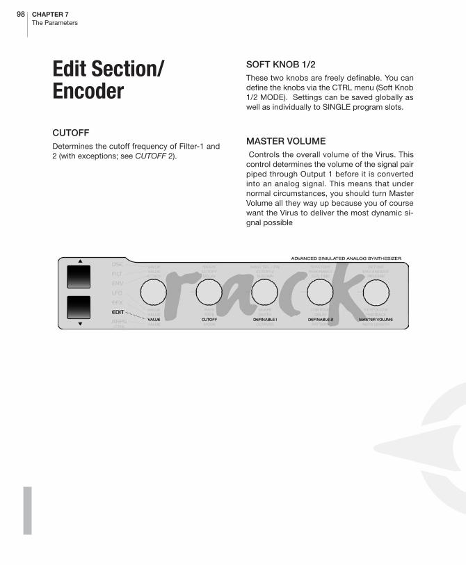
98 CHAPTER 7The Parameters
Edit Section/Encoder
CUTOFFDetermines the cutoff frequency of Filter-1 and2 (with exceptions; see CUTOFF 2).
SOFT KNOB 1/2These two knobs are freely definable. You candefine the knobs via the CTRL menu (Soft Knob1/2 MODE). Settings can be saved globally aswell as individually to SINGLE program slots.
MASTER VOLUME Controls the overall volume of the Virus. Thiscontrol determines the volume of the signal pairpiped through Output 1 before it is convertedinto an analog signal. This means that undernormal circumstances, you should turn MasterVolume all they way up because you of coursewant the Virus to deliver the most dynamic si-gnal possible

ACCESS VIRUS RACK XL OS5 99Clock Tempo
PDF VERSION - RESTRICTIONS APPLY
Edit Section/Menu
� CLOCK TEMPO
The Virus is equipped with a global clock gener-ator that lets you sync LFOs, arpeggiators anddelay effects up to a common song tempo andrhythm. The clock generator works either inter-nally with a freely variable speed or it can in turnby synced up to the MIDI clock of an externalsequencer. This synchronization occurs auto-matically when the device receives a MIDI clocksignal via its MIDI In. You can vary the speed ofthe clock generator within a range of 63 to 190BPM (beats per minute) via CLOCK TEMPO.When the device is synchronized via MIDIclock, the clock generator automatically ac-cepts the speed dictated by the connected se-quencer; the internal tempo is invalid. Theindividual sections of the Virus are synced up tothe clock generator at rhythmic intervals suchas 1/16, 1/4 and so forth. These values may beassigned individually for every section. (AR-PEGGIATOR CLOCK, CLOCK LFO 1, CLOCKLFO 2, CLOCK LFO 3, DELAY CLOCK, see therespective sections).
01111111111111111112
1 CLOCK Tempo(bpm) 120≤61111111111111111154
In SINGLE MODE, CLOCK TEMPO pertains tothe current SINGLE PROGRAM and is storedalong with it. In MULTI MODE, the CLOCKTEMPO settings for the involved SINGLE PRO-GRAMs are ignored. Instead, all involved SIN-
GLE PROGRAMs are controlled via the sameclock generator. Its CLOCK TEMPO is saved inthe MULTI PROGRAM (as are the settings of theglobal delay effect). This feature lets you controlthe LFOs and arpeggiators of several MULTIPARTS in a common rhythmic context.
A small “c”will appear in the display when theVirus is receiving MIDI Clock data.
If you’re sure you do NOT want the device to besynchronized automatically to MIDI clock, setMIDI CLOCK RX to Off (in the CTRL menu).
� To avoid confusion, please keep in mind thatMIDI Clock is not the same thing as MIDI TimeCode. The latter doesn’t deal with tempo at allbut with time-related information structured inhours, minutes, seconds, etc. which is of nobenefit to you in this context.
� COMMON
PATCH VOLUMEStorable master volume for the SINGLE pro-gram. Its nominal value is set to 100 so that youhave a reserve of 27 volume increments whenyou are dealing with exceptionally low-levelsound settings. In addition to using PATCHVOLUME, you can also control the level viaMIDI using the controllers #7 (Channel Volume)and #11 (Expression). However, these are notstored with the SINGLE program.. In MULTI
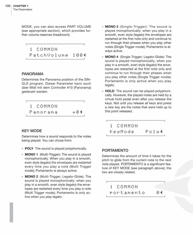
100 CHAPTER 7The Parameters
MODE, you can also access PART VOLUME(see appropriate section), which provides fur-ther volume reserves (headroom).
01111111111111111112
1 COMMON PatchVolume 100≤61111111111111111154
PANORAMADetermines the Panorama position of the SIN-GLE program. Dieser Parameter kann auchüber Midi mit dem Controller #10 (Panorama)gesteuert werden.
01111111111111111112
1 COMMON Panorama +0≤61111111111111111154
KEY MODEDetermines how a sound responds to the notesbeing played. You can chose from:
- POLY The sound is played polyphonically.
- MONO 1 (Multi-Trigger): The sound is playedmonophonically. When you play in a smooth,even style (legato) the envelopes are restartedevery time you play a note (Multi Triggermode); Portamento is always active.
- MONO 2 (Multi-Trigger; Legato-Glide): Thesound is played monophonically; when youplay in a smooth, even style (legato) the enve-lopes are restarted every time you play a note(Multi Trigger mode); Portamento is only ac-tive when you play legato.
- MONO 3 (Single-Trigger): The sound isplayed monophonically; when you play in asmooth, even style (legato) the envelopes arerestarted at the first note only and continue torun through their phases when you play othernotes (Single Trigger mode); Portamento is al-ways active.
- MONO 4 (Single-Trigger; Legato-Glide): Thesound is played monophonically; when youplay in a smooth, even style (legato) the enve-lopes are restarted at the first note only andcontinue to run through their phases whenyou play other notes (Single Trigger mode);Portamento is only active when you playlegato.
- HOLD The sound can be played polyphoni-cally. However, the played notes are held by avirtual hold pedal even after you release thekeys. Not until you release all keys and pressa new key are the notes that were held up tothis point released.
01111111111111111112
1 COMMON KeyMode Poly≤61111111111111111154
PORTAMENTODetermines the amount of time it takes for thepitch to glide from the current note to the nextnote played. PORTAMENTO is a significant fea-ture of KEY MODE (see paragraph above); thetwo are closely related.
01111111111111111112
1 COMMON portamento 0≤61111111111111111154

ACCESS VIRUS RACK XL OS5 101Common
PDF VERSION - RESTRICTIONS APPLY
TRANSPOSETransposes the entire SINGLE program by sem-itones.
01111111111111111112
1 COMMON Transpose 0≤61111111111111111154
BEND UPDetermines the interval of the bend when thePitch Bender is moved upwards to the full ex-tent of its range. Control range: -64 semitonesto +63 semitones.
01111111111111111112
1 COMMON BendUp +2≤61111111111111111154
BEND DOWNDetermines the interval of the bend when thePitch Bender is moved downwards to the fullextent of its range. Control range: -64 semi-tones to +63 semitones.
01111111111111111112
1 COMMON BendDown -2≤61111111111111111154
BEND SCALEDetermines the shape of the curve which in turndetermines the effect of the Pitch Bend data.You can chose from:
- LIN Starting from the 0 value, (center posi-tion) the pitch bend is linear. In other words,when you bend the pitch up to exactly halfthe distance of the pitch bend’s full range, theinterval you hear is equivalent to exactly halfof the value you set for BEND UP (see para-graph above).
- EXP Starting from the 0 value (center posi-tion) the pitch bend is exponential - at first thebend is gradual and as you move furtheraway from the center position, the pitch isbent ever more radically. In this mode you canachieve slight fluctuations in pitch, for in-stance a manual vibrato, provided you canmaintain a soft touch, yet still have the optionof generating greater intervals because of theexponential increase in range.
01111111111111111112
1 COMMON BendScale Exp≤61111111111111111154
SMOOTH MODEThis is an adaptive parameter smoothing mode(Adaptive Control Smoothing). You’ll find a de-tailed explanation of this parameter in the se-quencer chapte r. [ “Notes on Adapt i veParameter Smoothing” on page 138].
You have the following options to chose from:
- OFF Adaptive Control Smoothing is disabledand parameter changes are carried out incre-mentally without smoothing.
- ON Adaptive Control Smoothing is enabledand parameter changes are smooth.

102 CHAPTER 7The Parameters
- AUTO Adaptive Control Smoothing analyz-es the characteristics of the incoming in pa-rameter changes and carries out these outeither continuously (smoothed) or incremen-tally.
- NOTE Adaptive Control Smoothing is carriedout continuously (smoothed), but jumps insteps when a new note is played.
01111111111111111112
1 COMMON SmoothMode On≤61111111111111111154
� UNISON
MODEdetermines how many voices the Virus will useto render a played note. In a nutshell, it deter-mines how fat or big the sound will be. Whenyou activate UNISON mode for a sound, it canstill be played polyphonically. However, de-pending on the number of voices you’ve dialedin, its polyphony will of course be considerablyreduced in UNISON mode. The most efficientand the standard setting is UNISON mode =Twin, where two voices are played for everynote. In the OFF position, one voice per note isplayed.
01111111111111111112
1 UNISON Mode Twin≤61111111111111111154
DETUNESlightly detunes the voices involved in UNISONmode.
01111111111111111112
1 UNISON Detune 48≤61111111111111111154
PAN SPREADCreates a stereo panorama spread of the voicesinvolved in UNISON mode. Use it connectionwith UNISON DETUNE to create intense stereoeffects.
Moreover, PAN SPREAD lets you spread thestereo panorama of the two oscillators or filter,provided that you select SPLIT as the FILTERROUTING option (more on this in the section,”FILTER ROUTING”). Then this option is ena-bled regardless of whether or not UNISONmode is active. This feature allows you to createa stereo sound with just a single voice.
01111111111111111112
1 UNISON PanSpread 127≤61111111111111111154
UNISON LFO PHASEShifts the phases of the two TWIN MODE voic-es’ LFOs relatively. This effect livens up modu-lations. The value range of -64 to +63 isequivalent to -180 to +180 degrees. LFO

ACCESS VIRUS RACK XL OS5 103Punch
PDF VERSION - RESTRICTIONS APPLY
PHASE pertains to all LFOs and does not impairthe phase response of the LFOs within either ofthe two voices.
01111111111111111112
1 COMMON LfoPhase 30≤61111111111111111154
� PUNCH
PUNCH INTENSITYHere you can influence the attack of the amplifi-er envelope to enhance the sound with a morepercussive, snappy kind of feel. You may haveguessed that PUNCH INTENSITY determinesthe intensity of this effect. PUNCH is only effec-tive when you have dialed in fairly short AT-TACK rates for the amplifier envelope.
01111111111111111112
1 PUNCH Intensity 64≤61111111111111111154
� ASSIGN/MOD MATRIX
The 6 ASSIGN options let you control up to 9modulation destinations via up to 6 modulationsources. Simply go to ASSIGN, select one of
the modulation sources (SOURCE) and one orseveral modulation destinations (DESTINA-TION). Each of these configurations features aparameter that determines modulation intensity(AMOUNT). ASSIGN 1,4,5 and 6 can each con-trol one modulation destination, ASSIGN 2 cancontrol two and ASSIGN 3 can control threemodulation destinations, each with independ-ent AMOUNTs.
For your SOURCEs, you have two differenttypes of modulation sources to chose from. Thefirst type comprises external MIDI controllerssuch as the modulation wheel or breath control-ler. We call these ”performance controllers” todistinguish them from sound parameters suchas CUTOFF and REVERB that may also be ac-cessed directly via MIDI controllers. (Althoughstrictly speaking, they’re on-board devices, themodulation wheels of the Virus kb and Virus in-digo are also considered to be external MIDIcontrollers since they are not actually compo-nent parts of the sound generation system).
The second type comprises the sound genera-tion system’s internal modulators, for example,LFOs and envelopes. These also have fixedmodulation assignments (LFO AMOUNT, ENVAMOUNT), but are freely available along withthe Modulation Matrix.
Let’s take a look at the internal modulationsources:
- AMPENV & FILTENV The corresponding en-velope is the modulation source.
- LFO1, LFO2, LFO3 The corresponding LFOis the modulation source.
- VELOON The note on velocity is the modula-tion source.
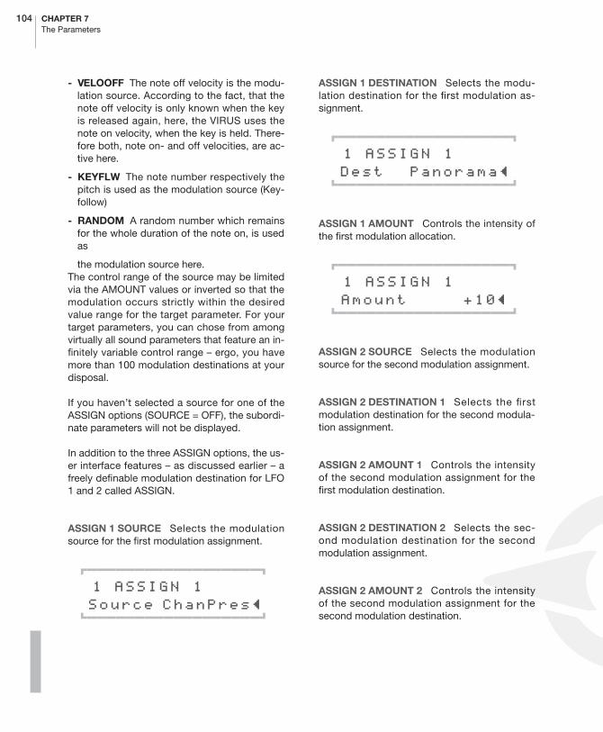
104 CHAPTER 7The Parameters
- VELOOFF The note off velocity is the modu-lation source. According to the fact, that thenote off velocity is only known when the keyis released again, here, the VIRUS uses thenote on velocity, when the key is held. There-fore both, note on- and off velocities, are ac-tive here.
- KEYFLW The note number respectively thepitch is used as the modulation source (Key-follow)
- RANDOM A random number which remainsfor the whole duration of the note on, is usedas
the modulation source here.The control range of the source may be limitedvia the AMOUNT values or inverted so that themodulation occurs strictly within the desiredvalue range for the target parameter. For yourtarget parameters, you can chose from amongvirtually all sound parameters that feature an in-finitely variable control range – ergo, you havemore than 100 modulation destinations at yourdisposal.
If you haven’t selected a source for one of theASSIGN options (SOURCE = OFF), the subordi-nate parameters will not be displayed.
In addition to the three ASSIGN options, the us-er interface features – as discussed earlier – afreely definable modulation destination for LFO1 and 2 called ASSIGN.
ASSIGN 1 SOURCE Selects the modulationsource for the first modulation assignment.
01111111111111111112
1 ASSIGN 1 Source ChanPres≤ 61111111111111111154
ASSIGN 1 DESTINATION Selects the modu-lation destination for the first modulation as-signment.
01111111111111111112
1 ASSIGN 1 Dest Panorama≤ 61111111111111111154
ASSIGN 1 AMOUNT Controls the intensity ofthe first modulation allocation.
01111111111111111112
1 ASSIGN 1 Amount +10≤ 61111111111111111154
ASSIGN 2 SOURCE Selects the modulationsource for the second modulation assignment.
ASSIGN 2 DESTINATION 1 Selects the firstmodulation destination for the second modula-tion assignment.
ASSIGN 2 AMOUNT 1 Controls the intensityof the second modulation assignment for thefirst modulation destination.
ASSIGN 2 DESTINATION 2 Selects the sec-ond modulation destination for the secondmodulation assignment.
ASSIGN 2 AMOUNT 2 Controls the intensityof the second modulation assignment for thesecond modulation destination.

ACCESS VIRUS RACK XL OS5 105Assign/Mod Matrix
PDF VERSION - RESTRICTIONS APPLY
ASSIGN 3 SOURCE Selects the modulationsource for the third modulation assignment.
ASSIGN 3 DESTINATION 1 Selects the firstmodulation destination for the third modulationassignment.
ASSIGN 3 AMOUNT 1 Controls the intensityof the third modulation assignment for the firstmodulation destination.
ASSIGN 3 DESTINATION 2 Selects the sec-ond modulation destination for the third modu-lation assignment.
ASSIGN 3 AMOUNT 2 Controls the intensityof the third modulation assignment for the sec-ond modulation destination.
ASSIGN 3 DESTINATION 3 Selects the thirdmodulation destination for the third modulationassignment.
ASSIGN 3 AMOUNT 3 Controls the intensityof the third modulation assignment for the thirdmodulation destination.
ASSIGN 4 SOURCE Selects the modulationsource for the first modulation assignment.
ASSIGN 4 DESTINATION Selects the modu-lation destination for the first modulation as-signment.
ASSIGN 4 AMOUNT Controls the intensity ofthe first modulation allocation.
ASSIGN 5 SOURCE Selects the modulationsource for the first modulation assignment.
ASSIGN 5 DESTINATION Selects the modu-lation destination for the first modulation as-signment.
ASSIGN 5 AMOUNT Controls the intensity ofthe first modulation allocation.
ASSIGN 6 SOURCE Selects the modulationsource for the first modulation assignment.
ASSIGN 6 DESTINATION Selects the modu-lation destination for the first modulation as-signment.
ASSIGN 6 AMOUNT Controls the intensity ofthe first modulation allocation.
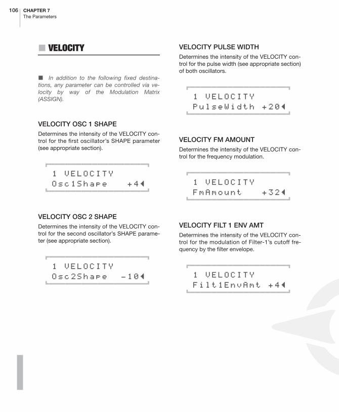
106 CHAPTER 7The Parameters
� VELOCITY
� In addition to the following fixed destina-tions, any parameter can be controlled via ve-locity by way of the Modulation Matrix(ASSIGN).
VELOCITY OSC 1 SHAPEDetermines the intensity of the VELOCITY con-trol for the first oscillator’s SHAPE parameter(see appropriate section).
01111111111111111112
1 VELOCITY Osc1Shape +4≤61111111111111111154
VELOCITY OSC 2 SHAPEDetermines the intensity of the VELOCITY con-trol for the second oscillator’s SHAPE parame-ter (see appropriate section).
01111111111111111112
1 VELOCITY Osc2Shape -10≤61111111111111111154
VELOCITY PULSE WIDTHDetermines the intensity of the VELOCITY con-trol for the pulse width (see appropriate section)of both oscillators.
01111111111111111112
1 VELOCITY PulseWidth +20≤61111111111111111154
VELOCITY FM AMOUNTDetermines the intensity of the VELOCITY con-trol for the frequency modulation.
01111111111111111112
1 VELOCITY FmAmount +32≤61111111111111111154
VELOCITY FILT 1 ENV AMTDetermines the intensity of the VELOCITY con-trol for the modulation of Filter-1’s cutoff fre-quency by the filter envelope.
01111111111111111112
1 VELOCITY Filt1EnvAmt +4≤61111111111111111154
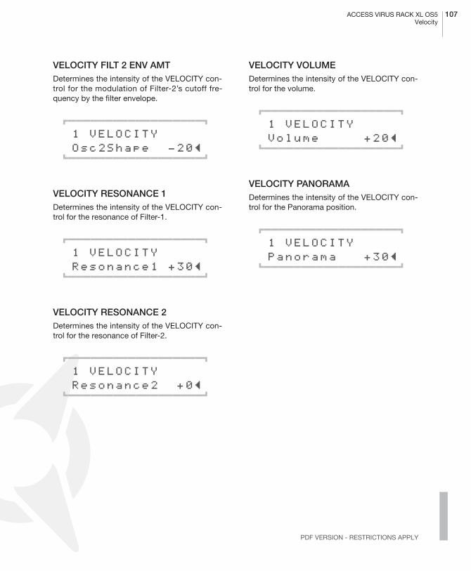
ACCESS VIRUS RACK XL OS5 107Velocity
PDF VERSION - RESTRICTIONS APPLY
VELOCITY FILT 2 ENV AMTDetermines the intensity of the VELOCITY con-trol for the modulation of Filter-2’s cutoff fre-quency by the filter envelope.
01111111111111111112
1 VELOCITY Osc2Shape -20≤61111111111111111154
VELOCITY RESONANCE 1Determines the intensity of the VELOCITY con-trol for the resonance of Filter-1.
01111111111111111112
1 VELOCITY Resonance1 +30≤61111111111111111154
VELOCITY RESONANCE 2Determines the intensity of the VELOCITY con-trol for the resonance of Filter-2.
01111111111111111112
1 VELOCITY Resonance2 +0≤61111111111111111154
VELOCITY VOLUMEDetermines the intensity of the VELOCITY con-trol for the volume.
01111111111111111112
1 VELOCITY Volume +20≤61111111111111111154
VELOCITY PANORAMADetermines the intensity of the VELOCITY con-trol for the Panorama position.
01111111111111111112
1 VELOCITY Panorama +30≤61111111111111111154
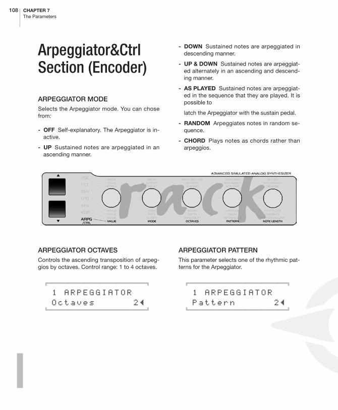
108 CHAPTER 7The Parameters
Arpeggiator&Ctrl Section (Encoder)
ARPEGGIATOR MODESelects the Arpeggiator mode. You can chosefrom:
- OFF Self-explanatory. The Arpeggiator is in-active.
- UP Sustained notes are arpeggiated in anascending manner.
- DOWN Sustained notes are arpeggiated indescending manner.
- UP & DOWN Sustained notes are arpeggiat-ed alternately in an ascending and descend-ing manner.
- AS PLAYED Sustained notes are arpeggiat-ed in the sequence that they are played. It ispossible to
latch the Arpeggiator with the sustain pedal.
- RANDOM Arpeggiates notes in random se-quence.
- CHORD Plays notes as chords rather thanarpeggios.
ARPEGGIATOR OCTAVESControls the ascending transposition of arpeg-gios by octaves. Control range: 1 to 4 octaves.
01111111111111111112
1 ARPEGGIATOR Octaves 2≤61111111111111111154
ARPEGGIATOR PATTERNThis parameter selects one of the rhythmic pat-terns for the Arpeggiator.
01111111111111111112
1 ARPEGGIATOR Pattern 2≤61111111111111111154
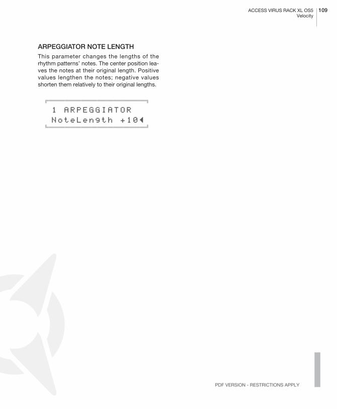
ACCESS VIRUS RACK XL OS5 109Velocity
PDF VERSION - RESTRICTIONS APPLY
ARPEGGIATOR NOTE LENGTHThis parameter changes the lengths of therhythm patterns’ notes. The center position lea-ves the notes at their original length. Positivevalues lengthen the notes; negative valuesshorten them relatively to their original lengths.
01111111111111111112
1 ARPEGGIATOR NoteLength +10≤61111111111111111154
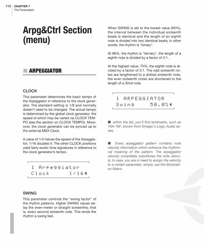
110 CHAPTER 7The Parameters
Arpg&Ctrl Section (menu)
� ARPEGGIATOR
CLOCKThis parameter determines the basic tempo ofthe Arpeggiator in reference to the clock gener-ator. The standard setting is 1/8 and normallydoesn’t need to be changed. The actual tempois determined by the global clock generator, thespeed of which may be varied via CLOCK TEM-PO (see the section on CLOCK TEMPO). More-over, the clock generator can be synced up tothe external MIDI Clock.
A value of 1/4 halves the speed of the Arpeggia-tor; 1/16 doubles it. The other CLOCK positionsyield fairly exotic time signatures in reference tothe clock generator’s tempo.
01111111111111111112
1 Arpeggiator Clock 1/16≤61111111111111111154
SWINGThis parameter controls the "swing factor" ofthe rhythm patterns. Higher SWING values de-lay the even-meter or straight sixteenths; thatis, every second sixteenth note. This lends therhythm a swing feel.
When SWING is set to the lowest value (50%),the interval between the individual sixteenthbeats is identical and the length of an eighthnote is divided into two identical beats; in otherwords, the rhythm is "binary".
At 66%, the rhythm is "ternary", the length of aeighth note is divided by a factor of 2:1.
At the highest value, 75%, the eighth note is di-vided by a factor of 3:1. The odd sixteenth no-tes are lengthened to a dotted sixteenth note,the even sixteenth notes are shortened to thelength of a 32nd note.
01111111111111111112
1 ARPEGGIATOR Swing 50.0%≤61111111111111111154
� within the list, you’ll find landmarks, such as16A-16F, known from Emagic’s Logic Audio se-ries.
� Every arpeggiator pattern contains notevelocity information which enhance the rhythmi-cal meaning of the pattern. The arpeggiatorvelocity completely substitutes the note veloci-ty. In case, you are in need to assign the velocityto a certain parameter, simply use the Modulati-on Matrix.

ACCESS VIRUS RACK XL OS5 111Categories
PDF VERSION - RESTRICTIONS APPLY
HOLDWhen this parameter is activate, the arpeggia-tor continues to play after you release the keys.Not until you release all keys and press a newkey are the notes that were held up to this pointreleased.
01111111111111111112
1 ARPEGGIATOR Hold Off≤61111111111111111154
� CATEGORIES
CATEGORY 1/2
Every SINGLE sound can be assigned to up totwo categories by means of the parametersCATEGORY 1 and CATEGORY 2. For example,you could assign the attributes "Bass" and "Ac-id" or "Lead" and "Favorite 1" to a given sound.These categories may be changed at any timeand can be stored along with the sound. Thefactory sounds are assigned default categories.
01111111111111111112
1 CATEGORY Decay≤61111111111111111154
� SECOND OUTPUT/SURROUND
The SECOND OUTPUT function lets you selectanother mono or stereo out irrespective of whatthe other output assignments may be. The bal-ance of levels between the normal output andthis second output is infinitely variable.
SELECT
This parameter controls the balance of levelsbetween the normal and the second audio out-put. This means that, depending on the givenapplication, SECOND BALANCE can serve asan effect send knob when an external device ispatched in via the second output (or anotherPART of the VIRUS is patched in via the auxbuses). It also serves as a back/front knobwhen you want to create a quadraphonic signal.
01111111111111111112
1 SECOND OUTPUT SELECT OFF≤61111111111111111154
BALANCEWith this parameter, you can mix the output sig-nals of the PARTs individually to the secondoutput that you chose by means of the SELECToption. When it is set to the OFF position, youwill only hear only the conventional output;when it is set to 127, the signal is routed exclu-sively to the second output. The values in be-tween these two extremes determine theweighted balance between the conventionaland the second output.
In conjunction with the conventional output ofthe given sound, you end up with a quadra-phonic signal that is suitable for Surround appli-

112 CHAPTER 7The Parameters
cations. Using Panorama (left, right) and theSECOND OUTPUT Balance (front, back), youcan create a genuine quadraphonic mix in theVIRUS.
The second output can also serve as an FXloop. To this end, all you have to do is connect itto an external effects device. The Balance pa-rameter then serves as an effect send knob thatdetermines the balance between the direct (ordry) signal and the wet (or effect) signal. Whenyou opt to use one of the aux buses as a sec-ond output, the aux bus can also serve as an FXloop. You can route the aux signal to a PARTand have the PART process this signal further.
If no output has been selected for SECONDOUTPUT Select (Off), the Balance parameter isdisabled.
01111111111111111112
1 SECOND OUTPUT BALANCE OFF≤61111111111111111154

The Multi Mode Parameters

114 CHAPTER 8The Multi Mode Parameters
Multimode param-eters
The MULTI mode parameters feature a dedicat-ed menu called the Multi Edit menu. Access itby pressing the Multi button while the device isin MULTI mode. The LED located over the MUL-TI button will light up to indicate that the MultiEdit menu is active. Press the MULTI buttonagain to return to normal Play mode. If the de-vice is in MULTI-SINGLE mode, press the MUL-TI and SINGLE buttons simultaneously toaccess the Multi Edit menu. It suffices to presseither the
MULTI or SINGLE button to return to normalPlay mode from MULTI-SINGLE mode.
� Please bear in mind the PART- and/orMULTI-related parameters described in the fol-lowing are available in MULTI mode only.
SELECT BANKActivates the bank for a SINGLE PROGRAM forthe current PART.
01111111111111111112
1 B36 101BASS RP SelectBank B≤61111111111111111154
SELECT NUMBERActivates a SINGLE PROGRAM for the currentPART.
01111111111111111112
1 B36 101BASS RP SelctNumber 36≤61111111111111111154
PART ENABLESwitches the MIDI receive mode of a givenPART ON and OFF, i.e. enables reception ofMIDI data.
01111111111111111112
1 B36 101BASS RP Part Enable On≤61111111111111111154
MIDI CHANNELSelects the MIDI channel of the PART. If two ormore PARTs are selected for the same MIDIchannel, these PARTs will be played simultane-ously. This creates what are generally calledlayer sounds.
01111111111111111112
1 B36 101BASS RP MidiChannel 1≤61111111111111111154
OUTPUT SELECTSeveral PARTs can simultaneously access theexternal outputs via OUTPUT SELECT.In SIN-GLE MODE, OUTPUT SELECT does not appearin the menu; in this case Output 1 (stereo) is

ACCESS VIRUS RACK XL OS5 115
PDF VERSION - RESTRICTIONS APPLY
preset.If the selected output is monophonic,then the Panorama settings and modulations inthe sound program are inactive.
PART TRANSPOSETransposes the PART in semitone steps.
01111111111111111112
1 B36 101BASS RP PartTransp +0≤61111111111111111154
PART DETUNEFine-tunes the PART.
01111111111111111112
1 B36 101BASS RP PartDetune +10≤61111111111111111154
PART VOLUMEControls the volume level of the PART. In addi-tion to PATCH VOLUME (in the EDIT menu, seeappropriate section), Channel Volume (Control-ler #7) and Expression (Controller #11), PARTVOLUME is the fourth option for determiningthe volume level of a PART within a MULTI pro-gram. Please keep in mind that PART VOLUMEis a bipolar parameter: In the negative half ofthe control range (-64 to 0) the signal level iscontrolled in the normal fashion - i.e. the soundfades out as negative numbers increase; fromthe center value upwards (0 to +63), extremelylow-level signals are amplified. When you setvalues greater than 0 for sounds that are al-ready fairly loud, you may hear undesirable dig-ital distortion.
01111111111111111112
1 B36 101BASS RP PartVolume +0≤61111111111111111154
- OUT 1 L The left jack of dual Out-put 1 (mono)
- OUT 1 L+R Both jacks of dual Output1 (stereo)
- OUT 1 R The right jack of dual Out-put 1 (mono)
- OUT 2 L The left jack of dual Out-put 2 (mono)
- OUT 2 L+R Both jacks of dual Output2 (stereo)
- OUT 2 R The right jack of dual Out-put 2 (mono)
- OUT 3 L The left jack of dual Out-put 3 (mono)
- OUT 3 L+R Both jacks of dual Output3 (stereo)
- OUT 3 R The right jack of dual Out-put 3 (mono)
- AUX 1 L The left channel of internalAux 1 (mono)
- AUX 1 L+R Both channels of internalAux 1 (stereo)
- AUX 1 R The right channel of inter-nal Aux 1 (mono)
- AUX 2 L The left channel of internalAux 2 (mono)
- AUX 2 L+R Both channels of internalAux 2 (stereo)
- AUX 2 R The right channel of inter-nal Aux 2 (mono)

116 CHAPTER 8The Multi Mode Parameters
CHAN VOLUME INITThis parameter relates to the Channel VolumeController (#7). ChanVolInit lets you determine apreset level that is activated when you switch tothis MULTI. This is an option that works well forlive applications, for example to set volume lev-els that will later be changed via an expressionpedal. When ChanVolInit is disabled (set toOFF), the initial Channel Volume value is re-tained when you switch to this MULTI. This ini-tial value may have been determined by theexpression pedal or by the most recently activeMULTI patch.
� Note: The Channel Volume Controller neverchanges when you switch from one SINGLE toanother. It always retains the most recently setvalue.
01111111111111111112
1 B36 101BASS RP PartDetune +10≤61111111111111111154
CHAN VOL RXENABLE Switches a given PART’s MIDI receivemode for MIDI Controller #7 (volume) on (Ena)and off (Dis).
01111111111111111112
1 B36 101BASS RP MidiVolume Dis≤61111111111111111154
PRIORITYThis parameter lets you control how the Vi-rus”steals notes when its polyphonic perform-ance is maxed out. In the first position, ”LOW”,
the voices of all PARTs have the same prioritywhen one voice is switched off to accommo-date a new voice. When you set the Priority of aPART to ”High”, the Virus will not ”steal” anynotes from the voices of this PART. Use this pa-rameter sparingly. In other words, if you set allParts to High, you’re defeating the purpose ofthis parameter. In this case, it wouldn’t have anyeffect since the priority of all voices is the same.
01111111111111111112
1 B36 101BASS RP ChanVolInit Off≤61111111111111111154
KEYRANGEIn MULTI mode, you can limit the note range ofindividual PARTs. Use the LowKey and HighKeyparameters to define the upper and lower limitsof the note range to which the PART will re-spond. This lets you assign the sounds of sev-eral PARTs that are addressed by the sameMIDI channel to different keyboard zones tocreate what are called split sounds.
If, however, you adjust the two parameters sothat the value of LowKey lies above that ofHighKey, the note range between these twohigh and low limits is disabled and the PART willrespond only to notes the lie above and belowthis zone.
� The two parameters may be entered in theusual way via the VALUE buttons and the VAL-UE knobs as well as directly via keyboard. Forthe latter option, press the VALUE buttons si-multaneously and then press the desired key onthe keyboard.

ACCESS VIRUS RACK XL OS5 117
PDF VERSION - RESTRICTIONS APPLY
LOW KEYDetermines the lowest MIDI note that the PARTresponds to.
01111111111111111112
1 B36 101BASS RP LowKey C-2≤61111111111111111154
HIGH KEYDetermines the highest MIDI note that the PARTresponds to.
01111111111111111112
1 B36 101BASS RP HighKey G8≤61111111111111111154
HOLD PEDALENABLE Switches a given PART’s MIDI receivemode for the hold pedal (MIDI Controller #64)ON and OFF.
01111111111111111112
1 B36 101BASS RP HoldPedal Ena≤61111111111111111154
PRG CHG ENABLESwitches a given PART’s MIDI receive mode forMIDI Program Change messages ON and OFF.
01111111111111111112
1 B36 101BASS RP ProgChange Ena≤61111111111111111154

118 CHAPTER 8The Multi Mode Parameters

The Global Parameters

120 CHAPTER 9The Global Parameters
Global Parame-ters/ System Sec-tion
� RANDOM PATCH GENERATOR
� The random patch generator can be found inthe RACNDOM PATCH GENERATOR chapter.
PAR DEPTHThis parameter determines the number ofsound parameters that are influenced by theRANDOM PATCH GENERATOR. If you enter alow value for PAR DEPTH, just a few parame-ters will be modified. Beyond that, the mannerin which the few parameters are edited assuresthat the sound is manipulated “organically”.This simply means that it isn’t bent radically sothat, for example, the given sound can still beplayed “tonally”.
As you increase the values for PAR DEPTH, oth-er parameters that have a greater impact on thetimbre of the sound are changed. At higher val-ues, the RANDOM PATCH GENERATOR tendsto generate noise-like sounds or special effects.
01111111111111111112
1 RANDOM [STORE] ParaDepth 0≤61111111111111111154
AMOUNTThis parameter determines the intensity of theRANDOM PATCH GENERATOR’s effect on thesound parameters. At lower values, soundchanges are fairly subtle, but you can intensifythe effect by repeatedly pressing the STOREbutton. Higher values introduce fundamentalchanges to the sound.
01111111111111111112
1 RANDOM [STORE] Amount 0≤61111111111111111154
� INPUT (GLOBAL)
INPUT DIRECT THRUThe stereo signal patched to the external inputscan be routed to the dual-jack Output 1 withoutbeing processed in any manner. For instanceyou can blend the output signal of anothersound generator with the output signal of theVirus and send the mixed signal to Output 1without having to use an external mixing con-sole. INPUT DIRECT THRU controls the level ofthis direct signal path.
This is a global parameter, i.e. it is not storedalong with the SINGLE PROGRAM.
01111111111111111112
1 INPUT GLOBAL DirectThru 0≤61111111111111111154
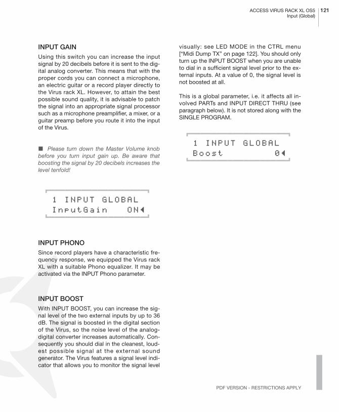
ACCESS VIRUS RACK XL OS5 121Input (Global)
PDF VERSION - RESTRICTIONS APPLY
INPUT GAINUsing this switch you can increase the inputsignal by 20 decibels before it is sent to the dig-ital analog converter. This means that with theproper cords you can connect a microphone,an electric guitar or a record player directly tothe Virus rack XL. However, to attain the bestpossible sound quality, it is advisable to patchthe signal into an appropriate signal processorsuch as a microphone preamplifier, a mixer, or aguitar preamp before you route it into the inputof the Virus.
� Please turn down the Master Volume knobbefore you turn input gain up. Be aware thatboosting the signal by 20 decibels increases thelevel tenfold!
01111111111111111112
1 INPUT GLOBAL InputGain ON≤61111111111111111154
INPUT PHONOSince record players have a characteristic fre-quency response, we equipped the Virus rackXL with a suitable Phono equalizer. It may beactivated via the INPUT Phono parameter.
INPUT BOOSTWith INPUT BOOST, you can increase the sig-nal level of the two external inputs by up to 36dB. The signal is boosted in the digital sectionof the Virus, so the noise level of the analog-digital converter increases automatically. Con-sequently you should dial in the cleanest, loud-est possible signal at the external soundgenerator. The Virus features a signal level indi-cator that allows you to monitor the signal level
visually: see LED MODE in the CTRL menu[“Midi Dump TX” on page 122]. You should onlyturn up the INPUT BOOST when you are unableto dial in a sufficient signal level prior to the ex-ternal inputs. At a value of 0, the signal level isnot boosted at all.
This is a global parameter, i.e. it affects all in-volved PARTs and INPUT DIRECT THRU (seeparagraph below). It is not stored along with theSINGLE PROGRAM.
01111111111111111112
1 INPUT GLOBAL Boost 0≤61111111111111111154

122 CHAPTER 9The Global Parameters
� MIDI
MIDI DUMP TX
This feature transfers the sound data of oneVirus to another Virus, a computer or a hard-ware sequencer via MIDI. The dump is exe-cuted via so-called system exclusive data(SysEx). You can chose from the followingdump options:
- TOTAL All data in the RAM of the Virus, inother words, the SINGLE Banks A and B, theMULTI programs, the EDIT buffers as well asthe settings for the global parameters.
- GLOBAL Here you can transfer all global da-ta (i.e. all parameters that are not stored witha Single or a Multi e.g. Global Channel).
- CONTROLLER DUMP This option lets yousend a Single to the MIDI Out in the form of acontroller dump. Here all parameters are sentin succession as individual parameter chang-es. The parameters are sent either as control-lers, polypressure or SysEx messages,depending on the setting in CTRL: MIDICONTROL LoPage / HiPage. This functionsends the SINGLE program that you are cur-rently processing (the contents of the Editbuffer).
The Controller Dump is not an alternative to anormal Single Dump since it takes so muchlonger to transmit data. However, it does al-low you to send a complete Single sound to aparameter-based editor (Logic Environment,Cubase Mixer) that is compatible with the Vi-rus for the purpose of updating the editor.
- SINGLE BUFFER This option dumps the da-ta of the SINGLE program that you are cur-rently processing (the Edit buffer).
- SINGLE BANK A All 128 sound programs ofBank A are sent.
- SINGLE BANK B All 128 sound programs ofBank B are sent.
- MULTI BUFFER This option dumps the dataof the MULTI program that you are currentlyprocessing (the MULTI’s Edit buffer). Pleasebear in mind that, with this option, merely theMULTI parameters and not the associatedSINGLE sounds are transmitted.
- ARRANGEMENT The current MULTI and theSINGLE programs involved can be transmit-ted in one go with this option. To shorten theamount of time that this dump takes, only thesounds of those PARTs whose Part Enableoption is set to On are sent.
- MULTI BANK All MULTI programs are trans-mitted with this option. Please bear in mindthat, with this option, merely the MULTI pa-rameters and not the associated SINGLEsounds are transmitted. If you want to save alldata of the Virus to a sequencer, you can se-lect the ”Total” dump option.
Once you have selected the desired datatype, the dump is initiated via STORE.
01111111111111111112
1 MIDI DUMP TX SingleBank A≤61111111111111111154
MIDI DUMP RXIf you want to send MIDI data to the Virus, youdon’t have to log in first. The Virus automaticallyaccepts incoming data via its MIDI In port.However, you can determine where the data ofa complete incoming bank is stored. In con-trast, single sound are always first dumped inthe Edit buffer; you have to manually store themsomewhere else, otherwise they are deleted bythe next program change.
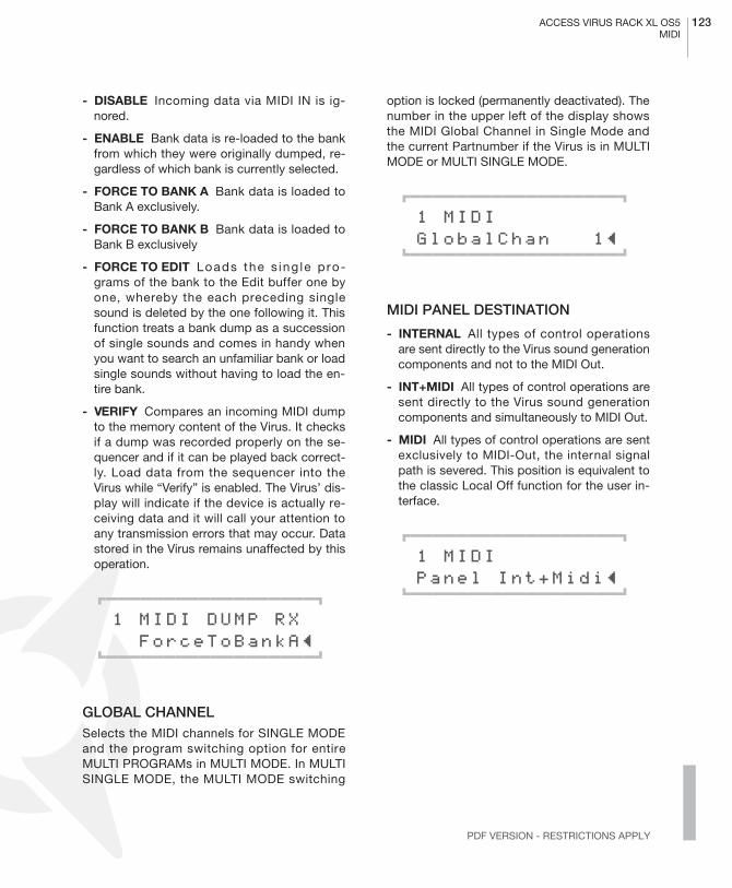
ACCESS VIRUS RACK XL OS5 123MIDI
PDF VERSION - RESTRICTIONS APPLY
- DISABLE Incoming data via MIDI IN is ig-nored.
- ENABLE Bank data is re-loaded to the bankfrom which they were originally dumped, re-gardless of which bank is currently selected.
- FORCE TO BANK A Bank data is loaded toBank A exclusively.
- FORCE TO BANK B Bank data is loaded toBank B exclusively
- FORCE TO EDIT Loads the s ing le p ro-grams of the bank to the Edit buffer one byone, whereby the each preceding singlesound is deleted by the one following it. Thisfunction treats a bank dump as a successionof single sounds and comes in handy whenyou want to search an unfamiliar bank or loadsingle sounds without having to load the en-tire bank.
- VERIFY Compares an incoming MIDI dumpto the memory content of the Virus. It checksif a dump was recorded properly on the se-quencer and if it can be played back correct-ly. Load data from the sequencer into theVirus while “Verify” is enabled. The Virus’ dis-play will indicate if the device is actually re-ceiving data and it will call your attention toany transmission errors that may occur. Datastored in the Virus remains unaffected by thisoperation.
01111111111111111112
1 MIDI DUMP RX ForceToBankA≤61111111111111111154
GLOBAL CHANNELSelects the MIDI channels for SINGLE MODEand the program switching option for entireMULTI PROGRAMs in MULTI MODE. In MULTISINGLE MODE, the MULTI MODE switching
option is locked (permanently deactivated). Thenumber in the upper left of the display showsthe MIDI Global Channel in Single Mode andthe current Partnumber if the Virus is in MULTIMODE or MULTI SINGLE MODE.
01111111111111111112
1 MIDI GlobalChan 1≤61111111111111111154
MIDI PANEL DESTINATION
- INTERNAL All types of control operationsare sent directly to the Virus sound generationcomponents and not to the MIDI Out.
- INT+MIDI All types of control operations aresent directly to the Virus sound generationcomponents and simultaneously to MIDI Out.
- MIDI All types of control operations are sentexclusively to MIDI-Out, the internal signalpath is severed. This position is equivalent tothe classic Local Off function for the user in-terface.
01111111111111111112
1 MIDI Panel Int+Midi≤61111111111111111154

124 CHAPTER 9The Global Parameters
ARPEGGIATOR SEND
This parameter determines whether or not (ONor OFF, respectively) the arpeggiator sends thenotes it generates to the MIDI Out. This functionis a feasible option only when you want to ad-dress further sound generators via MIDI.
01111111111111111112
1 MIDI ArpeggSend Off≤61111111111111111154
If you want to record notes generated by the Ar-peggiator to a sequencer, please ensure thatthese are not sent directly back to the Virus. Ifyou fail to do this, the Arpeggiator may no long-er be able to play correctly under these condi-tions. To avoid this situation, route data viaanother MIDI channel or switch off the MIDIThru function on your sequencer.
CLOCK RXThis parameter activates or deactivates the re-ceiving of MIDI-Clock globally. The Virus auto-matically detects the presence of MIDI-Clock(Auto). Therefore this parameter is not intendedto switch MIDI-Clock on, but to switch it off ifyou should feel that this is necessary (Off).
01111111111111111112
1 MIDI ClockRx Auto≤61111111111111111154
CHANNEL VOLUME ENABLEGlobally switches the reception of Volume data(Controller #7) on (ENA) or off (DIS).
01111111111111111112
1 MIDI MidiVolume Ena≤61111111111111111154
PROGRAM CHANGE ENABLEGlobally switches the reception of ProgramChange Data for SINGLE programs on and off.
01111111111111111112
1 MIDI ProgChange Ena≤61111111111111111154
MULTI PROGRAM CHANGE ENABLEThis function controls if the VIRUS receives pro-gram changes of multi-setups. If enabled, theVIRUS switches an entire multi-setup by a pro-gram change. The global MIDI channel has tobe used to receive the program change. Pleasenote that the multi program change will notwork in the single-multi mode, because, in thismode, the display is unable to show thechange.
01111111111111111112
1 MIDI MultiPrgChg Dis≤61111111111111111154

ACCESS VIRUS RACK XL OS5 125System
PDF VERSION - RESTRICTIONS APPLY
MIDI DEVICE IDHere you can enter the identification number forsystem exclusive data transfer. To enable com-munication between two Virus units - i.e. to ex-change system exclusive data - you mustassign the same MIDI DEVICE ID to both units.
01111111111111111112
1 MIDI DeviceId Omni≤61111111111111111154
MIDI CONTROL LOW PAGEHere you can determine if you want the first 128parameters (Page A) to be sent to MIDI-Out assystem exclusive data (SysEx) or as MIDI Con-trollers (Contr). When you set it to ”SysEx”, con-troller data is disabled on the receive side; if youset it to ”Contr”, both controller and SysEx dataare received.
01111111111111111112
1 MIDI CONTROL LowPage Contr≤61111111111111111154
MIDI CONTROL HIGH PAGEHere you can determine if you want the second128 (Page B) parameters to be sent as systemexclusive data (SysEx) or as MIDI PolyPressuredata (PolyPrs). When you set it to ”SysEx”,
polypressure data is disabled on the receiveside; if you set it to ”Contr”, both polypressureand SysEx data are received.
01111111111111111112
1 MIDI CONTROL HiPage PolyPrs≤61111111111111111154
� SYSTEM
MASTER TUNEDetermines the overall pitch of the Virus. 0 = A440 Hz. You can detune the device a half-noteup or down at the most.
01111111111111111112
1 SYSTEM Mastertune +0≤61111111111111111154
MEMORY PROTECTLocks (ON) or unlocks (OFF) the memory inwhich the sounds of the Virus are stored. Whenyou switch MEMORY PROTECT on, you canavoid inadvertent overwriting of programs whenyou accidentally press the STORE button.
01111111111111111112
1 SYSTEM MemProtect Off≤61111111111111111154
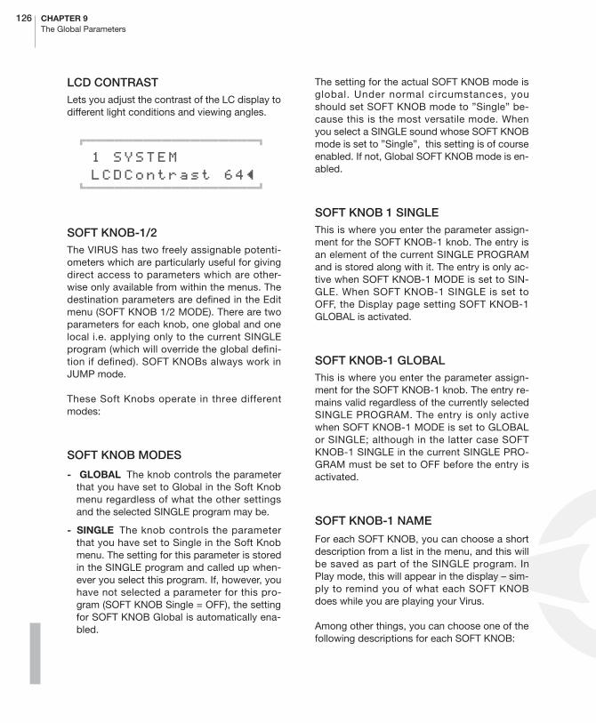
126 CHAPTER 9The Global Parameters
LCD CONTRASTLets you adjust the contrast of the LC display todifferent light conditions and viewing angles.
01111111111111111112
1 SYSTEM LCDContrast 64≤61111111111111111154
SOFT KNOB-1/2The VIRUS has two freely assignable potenti-ometers which are particularly useful for givingdirect access to parameters which are other-wise only available from within the menus. Thedestination parameters are defined in the Editmenu (SOFT KNOB 1/2 MODE). There are twoparameters for each knob, one global and onelocal i.e. applying only to the current SINGLEprogram (which will override the global defini-tion if defined). SOFT KNOBs always work inJUMP mode.
These Soft Knobs operate in three differentmodes:
SOFT KNOB MODES
- GLOBAL The knob controls the parameterthat you have set to Global in the Soft Knobmenu regardless of what the other settingsand the selected SINGLE program may be.
- SINGLE The knob controls the parameterthat you have set to Single in the Soft Knobmenu. The setting for this parameter is storedin the SINGLE program and called up when-ever you select this program. If, however, youhave not selected a parameter for this pro-gram (SOFT KNOB Single = OFF), the settingfor SOFT KNOB Global is automatically ena-bled.
The setting for the actual SOFT KNOB mode isglobal. Under normal circumstances, youshould set SOFT KNOB mode to ”Single” be-cause this is the most versatile mode. Whenyou select a SINGLE sound whose SOFT KNOBmode is set to ”Single”, this setting is of courseenabled. If not, Global SOFT KNOB mode is en-abled.
SOFT KNOB 1 SINGLEThis is where you enter the parameter assign-ment for the SOFT KNOB-1 knob. The entry isan element of the current SINGLE PROGRAMand is stored along with it. The entry is only ac-tive when SOFT KNOB-1 MODE is set to SIN-GLE. When SOFT KNOB-1 SINGLE is set toOFF, the Display page setting SOFT KNOB-1GLOBAL is activated.
SOFT KNOB-1 GLOBALThis is where you enter the parameter assign-ment for the SOFT KNOB-1 knob. The entry re-mains valid regardless of the currently selectedSINGLE PROGRAM. The entry is only activewhen SOFT KNOB-1 MODE is set to GLOBALor SINGLE; although in the latter case SOFTKNOB-1 SINGLE in the current SINGLE PRO-GRAM must be set to OFF before the entry isactivated.
SOFT KNOB-1 NAME
For each SOFT KNOB, you can choose a shortdescription from a list in the menu, and this willbe saved as part of the SINGLE program. InPlay mode, this will appear in the display – sim-ply to remind you of what each SOFT KNOBdoes while you are playing your Virus.
Among other things, you can choose one of thefollowing descriptions for each SOFT KNOB:
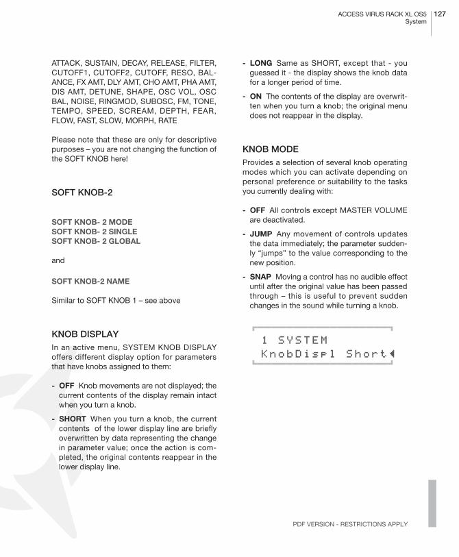
ACCESS VIRUS RACK XL OS5 127System
PDF VERSION - RESTRICTIONS APPLY
ATTACK, SUSTAIN, DECAY, RELEASE, FILTER,CUTOFF1, CUTOFF2, CUTOFF, RESO, BAL-ANCE, FX AMT, DLY AMT, CHO AMT, PHA AMT,DIS AMT, DETUNE, SHAPE, OSC VOL, OSCBAL, NOISE, RINGMOD, SUBOSC, FM, TONE,TEMPO, SPEED, SCREAM, DEPTH, FEAR,FLOW, FAST, SLOW, MORPH, RATE
Please note that these are only for descriptivepurposes – you are not changing the function ofthe SOFT KNOB here!
SOFT KNOB-2
SOFT KNOB- 2 MODE SOFT KNOB- 2 SINGLE SOFT KNOB- 2 GLOBAL
and
SOFT KNOB-2 NAME
Similar to SOFT KNOB 1 – see above
KNOB DISPLAYIn an active menu, SYSTEM KNOB DISPLAYoffers different display option for parametersthat have knobs assigned to them:
- OFF Knob movements are not displayed; thecurrent contents of the display remain intactwhen you turn a knob.
- SHORT When you turn a knob, the currentcontents of the lower display line are brieflyoverwritten by data representing the changein parameter value; once the action is com-pleted, the original contents reappear in thelower display line.
- LONG Same as SHORT, except that - youguessed it - the display shows the knob datafor a longer period of time.
- ON The contents of the display are overwrit-ten when you turn a knob; the original menudoes not reappear in the display.
KNOB MODEProvides a selection of several knob operatingmodes which you can activate depending onpersonal preference or suitability to the tasksyou currently dealing with:
- OFF All controls except MASTER VOLUMEare deactivated.
- JUMP Any movement of controls updatesthe data immediately; the parameter sudden-ly “jumps” to the value corresponding to thenew position.
- SNAP Moving a control has no audible effectuntil after the original value has been passedthrough – this is useful to prevent suddenchanges in the sound while turning a knob.
01111111111111111112
1 SYSTEM KnobDispl Short≤61111111111111111154

128 CHAPTER 9The Global Parameters
LED MODEHere you can chose between two operatingmodes for the RATE LEDs of LFO 1 and 2:
- LFO The LEDs indicate the oscillations of theLFOs.
- INPUT The LEDs serve as level indicators forthe two external audio inputs (RATE 1 = InputL; RATE 2 = Input R). The brightness of theLEDs indicates the current input level; signalsaturation is indicated by rapidly flashingLEDs.
To achieve maximum sound quality for the sy-stem, you should set the input signal to a le-vel that is as close as possible to thesaturation threshold. However you shouldavoid setting the level beyond the saturationthreshold, otherwise you will hear undesirabledistortion in the signal. You can also use thelevel indicators to see if an input signal is ac-tually patched in.
- AUTO When you activate AUTO, the LFORate LEDs will automatically indicate the in-put level when you switch to a SINGLE orPART that accesses an external audio out-puts.
- OUTPUT1
- OUTPUT2
- OUTPUT3
- AUX1
- AUX2 Much like when the setting «ExtIn» isenabled, you can have the two LFO RateLED’s indicate the signal levels of five furthersignal buses. This lets you check visually if asignal is being routed via a given bus andspot overloaded circuits. When you activatethis option, the LFO1 LED indicates the leftchannel and the LFO2 LED indicates the rightchannel of the selected signal bus. The LEDswill flash rapidly to indicated an overloadedbus.
- STEAL The ”Steal” setting indicates if avoice is cut off in the interest of providing thevoices required to render a new note whenev-er the polyphony that VIRUS has been ex-hausted. If the device is forced to cut a noteoff, it will select the voice whose signal levelhas dropped furthest. Considering that avoice fades out over a range of 0 to -144 dec-ibels, but – depending on the sonic context –the signal fades into the background at -32 to-48 decibels, this process of cutting off fadingnotes is largely inaudible. The brightness ofthe LFO Rate LED will fluctuate to indicatethe volume envelope’s current level for thenote that the VIRUS is cutting off.
01111111111111111112
1 SYSTEM LeadMode Auto≤ 61111111111111111154

The Vocoder

130 CHAPTER 10The Vocoder
� VOCODER
Although vocoder sounds have seen a come-back in the recent time, many musicians do notspecifically know how they work or even moreimportantly, how they sound! Various Vocoderpresets are stored In the last section of SINGLEbank D (grammalogue ”VOC”). These SINGLEsrequire an audio signal being fed to the externalinputs. The keyboard also needs to be playedon most of the presets. The Virus Vocoder is notnecessarily easy to handle. You should alwaysrefer to an existing Vocoder preset for editing.
The Vocoder is one of the most complex sec-tions of the Virus. For this reason, we recom-mend that you use factory sounds that use theVocoder as your point of departure and editthese to create your own sounds. This meansthat you don’t have to start from scratch andthat the Vocoder’s parameters are set to viablevalues, which will facilitate programming con-siderably.
A Vocoder creates a new sound by combiningtwo signals. The timbre of the so called analysissignal (or modulator signal) forms the carriersignal. A typical example for a modulator signalis the human voice, another suitable carrier sig-nal can be a steady tone with rich harmonics.
The sound characteristic is being rendered intothe new sound by two cascades of bandpassfilters: The modulator signal is being sendthrough several parallel bandpass filters, whichonly pass through a certain part of the wholespectrum. Every bandpass filter is followed byan envelope follower which uses the level of thesignal to create a control signal. This part of thevocoder is called a modulator bank.
The carrier signal is treated in a similar way. It issplit into several bands by a chain of bandbassfilters. Different to the technique used above,
the bandpass filters are not followed by enve-lope followers. The circuit uses amplifiers whichare levelled by the control signal output of theenvelope followers of the modulator banks. Thispart of the vocoder is called the carrier bank orsynthesis part.
As soon as the modulator detects a signal in acertain frequency range, its envelope followerlevels the corresponding band in the synthesispart. In other words: Just the frequency band ofthe carrier signal (the steady tone), which is apart of the modulator signal (the spoken voice)in this second, is being passed to the output.This is why the steady tone starts to speak. Thepitch of the output signal depends on the carri-er. If a cord, e.g. a polyphonic pad sound is be-ing used instead on a single tone, you can listento a typical vocoder choir. Of course, you canuse a different Modulator than a spoken voice.Have a try with a drumloop!
All you need is the internal synthesizer of the Vi-rus. It is also possible to process external sig-nals. The feature set of the VIRUS includes 32filter bands, shifting the frequency’s relation ofmodulator and carrier, adjustable quality (Q-fac-tor) of the filter bands and much more.
The VIRUS’s vocoder consists of different sec-tions which perform different tasks:
THE MODULATOR BANKThis cascade of bandpass filters split the fre-quency spectrum of the modulator into slices,quite similar to the way a studio frequency ana-lyser would.
THE ENVELOPE FOLLOWERThe level at the output of each bandbass filter ismeasured by the modulator bank. The resultingcontrol signal can be modified by an ATTACK
ACCESS VIRUS RACK XL OS5 131The parameters of the Virus vocoder
PDF VERSION - RESTRICTIONS APPLY
and DECAY parameter. These signals are noaudio signals, as they contain the envelope ofthe signal being analysed.
THE CARRIER BANKThe signal is treated in a similar way to the sig-nal which passes the modulator bank. In thiscase, the carrier signal is split by the bandpassfilters. Each bandpass of the carrier bank corre-sponds to one of the modulator bank. Usually,both bandpasses use the same frequency slice.Similar to a synthesizer’s envelope, the signallevel being measured by the envelope followersof the modulator, is used to control the level ofthe carrier’s filter. Last, but not least, the individ-ually controlled signals of the carrier bank arereunified to create the vocoder’s output sound.
� THE PARAMETERS OF THE VIRUS VOCODER
� The Vocoder related parameters are locatedin the EFFECT Menu [“Vocoder” on page 94]
VOCODER MODEhere you can enable the vocoder and choosethe signal source for the carrier bank at thesame time:
- OSC This mode uses the whole oscillatorsection of the Virus, including the noise gen-erator as the carrier signal. The oscillatorscan be played polyphonic which enables theamplifier envelope to work as usual. But theoscillator signal does not pass the filter sec-tion,
- OSC-HOLD This sett ing is ident ica l to”OSC” although the hold-mode (which also isavailable at COMMON/KeyMode) is activat-ed.
- NOISE White noise is used as the carrier.The oscillator section is disabled.
- IN (L / In L+R / In R) The analog inputs arethe carrier signal. If a stereo source, like L+R,is chosen, the left and right signal is mixed tocreate a mono signal.
OSC VOLOSC VOL adjusts the output level of the vocod-er. This is independent of the signal source(which can be assigned using the vocodermode parameter)
INPUT SELECTWhile INPUT Select regularly assigns the inputsource for INPUT Mode, the modulator bank in-put is assigned here, when the vocoder is acti-vated. Again, stereo sources like L+R are mixedto a monophonic signal.
MODULATOR FREQUENCY OFFSETA linear shift of the modulator bank’s central fre-quencies against the carrier bank, results inpitch-shifting and ”mickey mouse” effects.CUTOFF2 creates an offset of the modulator tothe carrier bank.

132 CHAPTER 10The Vocoder
Q-FACTORThe resonance parameter controls the quality ofthe filter bands (like an equalizer’s q-factor). Alow quality factor of the carrier bank leads to afairly neutral reproduction of the carrier signal. Ahigher quality creates a higher resonance in thefilter bands, which therefore make the overallsounds more artificial.
VOCODER ATTACKThe attack time of the envelope follower. Thisparameter controls how fast the carrier bandsreact on a change of the modulator signal’s fre-quency energy. Higher values result in a ”flab-by”, lazy, even delayed response from thevocoder.
VOCODER RELEASEThe release time of the envelope follower. Thisparameter controls how fast the carrier bandsreflect if a certain frequency disappears fromthe spectrum of the modulator signal. Here,higher values result in a kind of sustain in thecarrier bands. High attack and release timeslead to less speech recognition, although it ispossible to create a really nice sounding syn-thesizer pads with.
VOCODER SOURCE BALANCE FILTER BALANCE creates a mixture of the voc-oder signal and the modulator-respectively car-rier signal. Turning FILTER BALANCE to the leftadds a certain amount of the carrier signal tothe vocoder signal. A turn to the right adds themodulator signal.
� Turning the FILTER BALANCE hard left orright can be used to monitor the vocoder’s inputsignals only.
VOCODER SPECTRAL BALANCESpectral balance between the higher and lowerfrequencies of the vocoder signal. This parame-ter works similar to a simple equalizer, which ise.g. capable to increase the quality of speech.The Spectral Balance highly influences theoverall character of the vocoder.
Several vocoder related parameters can bemodulated by LFO-1 and LFO-2
- LFO 1 RESO 1+2 modulates the bandpassfilter quality of the modulator and carrierbank.
- LFO 2 FILT 1 modulates the bandpass filterfrequency of the carrier bank.
- LFO 2 FILT 2 modulates the bandpass filterfrequency of the modulator bank.
� NOTES ABOUT THE VOCODER
The vocoder can also be controlled by any partof the multimode. If more than one part of themultimode contains an activated vocoder, onlythe vocoder of the part with the lowest partnumber is active.
As mentioned before, the whole filter section isexchanged to the vocoder, parameters, param-eters like saturation or the filter routing are notavailable anymore.
If you would like to use the vocoder as an exter-nal effect device, choose one external input inthe VOCODER MODE parameter page (modula-tor signal) and the carrier signal by the INPUTSELECT page.

ACCESS VIRUS RACK XL OS5 133Notes about the vocoder
PDF VERSION - RESTRICTIONS APPLY
The effect section (chorus, delay) and the out-put selection can be used in a vocoder patch.

134 CHAPTER 10The Vocoder

The Virus and Sequencers

136 CHAPTER 11The Virus and Sequencers
� PARAMETER CONTROL VIA MIDI
Virtually all parameters of the Virus are accessi-ble via MIDI so that, for example, you can ma-nipulate knobs and buttons and record thesemovements to a sequencer. You may then routethese commands back to the Virus, which willrespond to these automated instructions auto-matically. MIDI controllers have proven effectivefor this external control option since these com-mands – in contrast to system exclusive data –are transported very swiftly. Beyond that,they’re easy to edit graphically in all standardsequencer programs.
� ORGANIZATIONAL INFORMATION
In order to be able to record the movements ofknobs and status changes of buttons on the Vi-rus to a sequencer, you must connect the MIDIOut of the Virus to the MIDI In of the computeror sequencer. You also have to enable receptionof MIDI controllers and MIDI polypressure com-mands in the sequencer so that this data is notsubject to one-sided filtering. Whenever appro-priate, you also have to enable reception of thisautomation data on the Virus. To this end, go tothe Cntrl menu and take a look at the MIDI pa-rameters. You’ll find a parameter called Panelthat offers the options Internal, Internal+Midiand MIDI. This is where you determine the des-tination to which the knobs and buttons sendtheir data. Internal means that the knobs andbuttons send data exclusively to the soundgenerator and not to MIDI. Therefore, select In-
ternal+Midi or MIDI so that data is sent to thesequencer via MIDI. Note that the MIDI optiondisconnects the knobs and buttons from the Vi-rus’ internal sound generation system. Whenthis setting is enabled, data generated by knobsand buttons is only acknowledged by the Viruswhen it is routed back in a roundabout way viathe computer/sequencer (the Virus must be se-lected as a track instrument in the sequencerand the ”Thru” function of the sequencer mustbe activated).
Now scroll to the two parameters called LoPageand HiPage: LoPage should be set to Contr(MIDI controller), HiPage to PolyPrs (MIDI poly-pressure). There are only 128 controller num-bers per MID I channe l , so tha t no t a l lparameters of a Virus PART can be covered bycontrollers. On the Virus, this problem wassolved by splitting up its parameters into threeParameter PAGEs for data transport purposes.Each of these three PAGEs can contain up to128 parameters. A SINGLE program consists ofthe parameters of the two first PAGEs. Parame-ters of the first PAGE are assigned to the MIDIcontrollers, while the parameters of the secondPAGE are sent and received by so-called poly-pressure data. This structure of this data type isidentical to that of controllers; polypressure isalso supported by sequencer programs. (Thisdata type was initially created to allow the pres-sure exerted on keys to be transmitted poly-phonically, but this required a special approachto playing that never really caught on. The Virusis the first instrument to exploit this data type inthe interest of putting further controllers at yourdisposal.)
� Please note that the Virus allows you to con-trol several PARTs via the same MIDI channel.This means that an incoming controller wouldcollectively address this parameter in all PARTs.This of course defeats the purpose of routingseveral of these PARTs via the same channel,which is to double up different sounds. For this

ACCESS VIRUS RACK XL OS5 137Handling MIDI Parameter Control
PDF VERSION - RESTRICTIONS APPLY
reason, the convention in the Virus is that, whenseveral of these PARTs are patched through asingle MIDI channel, only the PART with thelowest PART number is addressed by incomingcontrollers; all other PARTs ignore this data.This applies solely to sound parameters and notto so-called performance controllers such asthe modulation wheel.
As an alternative to parameter control via con-troller and polypressure data, you have the con-ventional system exclusive control optionavailable, see ”MIDI Implementation” in the ap-pendix [“System Exclusive Data” on page 158].This system exclusive control option may beactivated independently for the first two Param-eter PAGEs (under MIDI in the CTRL menu), inwhich case this control mode is the only type ofremote control option that is active – you getexclusively system exclusive control, as it were.The third parameter PAGE, in turn, lets you con-trol the parameters of the current MULTI PRO-GRAM as wel l as g lobal and/or systemparameters. This third PAGE is addressed sole-ly via system exclusive MIDI messages. The ad-vantage of system exclusive control is that youcan address PARTs individually irrespective ofwhat their current MIDI channel assignmentsmay be.
You’ll find a list of all controller and polypres-sure assignments in the appendix. [“ParameterDescriptions” on page 162]
� HANDLING MIDI PARAMETER CONTROL
If you have configured your MIDI system in ac-cordance with the instructions in the previoussection, you may activate the sequencer’s re-cording mode and record the knob and buttonmovements as you see fit. Check the Event orList editor of your sequencer to see if the re-cording operation was successful.
Good-to-know info: Do not record knob andbutton movements to the same track that con-tains the notes of any given passage. Instead,use a new track that sends its data to the sameMIDI output and channel as the track containingthe notes. Although the sequencer mergesthese two data streams internally, separatingthe two tracks makes it easier for you distin-guish between the information that they con-tain. Besides, you’re thus able to edit and copythe recording of t knob and button movementswithout affecting the actual notes on the othertrack.
If you wanted to take this an extreme, you couldrecord the movements of every knob and but-ton to a separate track. Although this soundslike a classic case of overkill, it can facilitate theprocess of editing the recorded sequences:Bear in mind that the sequencer doesn’t indi-cate the parameters addressed via the controlfeatures of the Virus by their names; instead, itindicates merely the controller and/or polypres-sure numbers. If you split up these control fea-tures by recording them to different tracks andgiving these tracks names that give you an ideaof what they contain, you’ll find it much easierto work with these tracks.
138 CHAPTER 11The Virus and Sequencers
� NOTES ON ADAPTIVE PARAMETER SMOOTHING
We developed a feature called Adaptive Param-eter Smoothing for the Virus that assures auto-mated knob movements are carried out so thatparameter changes are not audible in stepscommonly called zipper noise.
This means that the Virus responds just assmoothly to your sound-shaping actions as avintage analog synthesizer. To this end, the re-sponse of the Virus is manipulated so that itsmoothes changes in parameter value. Conven-iently, this feature is dynamic, meaning that ittakes into account the way these valueschange. However, smoothing is many cases un-desirable. For example, left to its own devices,this feature would smooth deliberate, more rad-ical knob movements where one value ”jumps”to the next, thus creating unintentional ”glitch-es”. For example, this type of response woulddefeat the purpose of effects generated by astep sequencer’s controller messages as wellas gater effects that you programmed in yoursequencer.
You can adjust Adaptive Parameter Smoothingvia a function called Control Smooth mode (inthe EDIT menu; COMMON: SmoothMode) toaccommodate different sonic situations:
- OFF Adaptive Control Smoothing (parametersmoothing) is disabled.
Application: Parameter jumps are carried outwithout glitches. This option is ideal when youwant to create gating and similar effects (e.g.via a step sequencer) where parameter valueschange abruptly.
Side effect: Continuous parameter changes –be it movements controlled via automatedknobs or via MIDI - are incremental, whichmeans you’ll have to take zipper noise intoaccount.
- ON Adaptive Control Smoothing is enabled.
Application: Parameter changes are carriedout continuously and smoothly.
Side effect: Parameter jumps are also carriedout continuously, meaning that glitches maybe generated inadvertently.
- AUTO Adaptive Control Smoothing analyz-es the nature of incoming parameter changesand carries these out continuously or abrupt-ly, as the case may be.
Application: Both continuous as well as sud-den parameter changes may be implementedin the same sound.
Side effect: This analysis of radical parameterchanges can’t cope with jumps that occur inrapid succession.
- NOTE Adaptive Control Smoothing workscontinuously, but jumps when a new note isplayed.
Application: Both continuous as well as sud-den parameter changes may be implement-ed, whereby the jumps are always inserted atthe beginning of a new note. Consequently,this option is well-suited when you want tocontrol sounds via a step sequencer.
Side effect: When you’re playing polyphoni-cally, parameter jumps also affect notes thatwere played previously and are still soundingwhen a new note is played.
The Control Smooth mode parameter setting isconsidered a component part of a SINGLEsound and is thus stored with it.
ACCESS VIRUS RACK XL OS5 139Problems Related to Parameter Control
PDF VERSION - RESTRICTIONS APPLY
� Step sequencers let you assign a new cutoffvalue for every note. You can create the sameeffect on a conventional sequencer. To this end,all you have to do is program a cutoff controllerin the sequencer for every note in the arrange-ment. However, be aware that conventional se-quencers can throw a spanner in the works: Ifthe timing of this type of controller coincidesprecisely with the timing of a note, the sequenc-er will first send the note command so that theoverall timing is not skewed by controller com-mands. For the purposes of our example, thismeans that the new cutoff value doesn’t arriveuntil just after the note has been played. Thiscan generate incidental artifacts. We recom-mend that you record the controllers separatelyto a track other than the one containing thenotes of a given sequence (make sure that thetrack addresses the same MIDI channel) andthat to assign a touch of predelay to this track(e.g. set Track Delay to -1). Then the cutoff val-ue is updated just before the new note arrives.Incidentally, this phenomenon is not unique tothe Virus, it is a design-related ”flaw” inherent inall synthesizers.
� PROBLEMS RELATED TO PARAMETER CONTROL
If you enjoy experimenting with recording pa-rameter changes, sooner or later, you will runinto the following problem: When controller se-quences are recorded to a sequencer, the lastrecorded value remains valid until another valueis sent for this controller. For example, if yougradually open a filter for a sound in the middleof the song and record this parameter change,the filter will stay open until the end of the songif you not close it manually or close it via con-
trollers. Moreover, when you start the song fromthe top, you’ll again hear the sound with the fil-ter open because the Virus hasn’t received acommand at the beginning of the song to closethe filter. Not until the song arrives at the posi-tion where the recorded event begins does theVirus receive the first controller value for the fil-ter. If, on the other hand, the song is startedwith the stored and unedited version of the filtersound, everything will be fine: The filter isclosed and won’t be opened until the recordedevent tells the Virus to do just that.
If you understand this connection between re-corded parameter changes and the current pa-rameter status of the Virus, you’ll find it easy tocome up with solutions for these kinds of prob-lems. Sticking with our example, you couldsend a controller value to the Virus that closesthe filter again in a suitable position within thesong, for instance, at some point after the filteropens or at the beginning of the song. However,this procedure can become tedious ratherquickly if you have recorded many parameterchanges – after all, what you’re actually doing isliterally copying the original values of differentparameter in order to enter them into the se-quencer. You could of course simply activatethe sound at the beginning of the song via aprogram change message, which resets the pa-rameters to their original stored values. What if,however, you change or replace the sound inthe Virus at some point? The program changemessage in the song would call up the wrongsound. The more reliable and certainly more el-egant solution would be to store the sound(s) inthe song. The Virus then receives all settings forsounds at the beginning the song, and you’dprevent hiccups such as the wrong sounds,”stuck” values and jumps from the get-go. Inthe next section, you’ll find out just how youcan do this.
140 CHAPTER 11The Virus and Sequencers
� DUMP - THE SOUND IN THE SONG
Archiving all of the sounds used in a song is notonly a good idea to prevent potential problemsthat may occur when parameters are controlledin real time. It also makes it easy for you to re-call your work at some later point. Assumingthat you’ve connected the MIDI Out of the Viruswith a MIDI In of the computer, you can, for ex-ample, at any time send an individual sound orthe content of the entire memory via MIDI in theform of something called a bulk dump to the se-quencer and record this data there. This has andistinct advantage: all sound data can bestored together with the song and the status ofthe Virus required for this song can be restoredat any time by simply sending the recorded da-ta to the device. You’ll find the menu for SysExdumps by going to the CTRL menu and thenMIDI DUMP TX.
When you opt to record a bulk dump to a se-quencer, you can proceed in the same manneras you would when you record tracks consist-ing of notes. For example, you can move a bulkdump to any position in the arrangement. To as-sure that the Virus plays the song back usingthe right sounds, we recommend that you posi-tion stored data prior to the song. Move allcomponents of the actual song back so thatyou’re left with enough room to accommodatethe dump prior to the song’s start position.Then when you start the sequencer on the firstbar, sound-related data is sent to the Virus be-fore the actual song begins. An individual sounddump is very short; a dump comprising a com-plete memory bank will extend over severalbars.
� During a bulk dump, the Virus sends MIDISysEx data to the computer. If you encounterproblems while recording a bulk dump, please
check if your sequencer refuses to accept Sy-sEx data due to one-sided filtering. You cancheck whether or not anything was recorded bytaking a look at the Event or List editor of yoursequencer. In this editor, MIDI data is displayednumerically instead of graphically; in a normalNote editor (Key Edit, Matrix Edit or the like) Sy-sEx data is NOT visible. Once you’ve success-fully recorded a dump, look for entries in the listthat are labeled ”SysEx”.
The Virus lets you to send the entire memorycontent or just parts thereof to the sequencer.The most reliable solution is to transfer the en-tire memory (MIDI DUMP TX: Total). There is,however, a catch: Since a great deal of data isbeing transmitted (”Total”, after all, means allSINGLE programs, all MULTIs, and so forth),the dump is very extensive and takes quitesome time. Alternatively, you can also send justindividual sounds, MULTIs or so-called ”ar-rangements”.
The other truly reliable option for archivingsounds is dumping an arrangement (MIDIDUMP TX: Arrangement). In this case, the cur-rent MULTI is transmitted. Since a MULTI con-tains the addresses of SINGLE sounds used inthe arrangement rather than the actual SIN-GLEs, the sounds of all active PARTs are sentseparately (for more info on this, see the sectionon MULTIMODE). This option is convenient andfast, but has an inherent drawback: this type ofarrangement dump does not take into accountthat your song uses program change messagesto change sounds in the MULTI. Only the eightsounds to which the MULTI refers in the ar-rangement are sent, which is to be expectedwhen you consider that the Virus can’t antici-pate that you intend to change these at somepoint during playback.
Dumping an arrangement is a great optionwhen you’re able to make do with the sixteensounds to which the MULTI refers. If you want
ACCESS VIRUS RACK XL OS5 141Dump - The Sound in the Song
PDF VERSION - RESTRICTIONS APPLY
to or are compelled to change sounds, youshould record the entire memory content to thesequencer. Sending individual MULTIs for thepurpose of archiving sounds is pointless be-cause they don’t contain the actual sounds.Sending individual sounds, in turn, is only a via-ble proposition if you are operating the Virus inSINGLE mode and have opted not to use pro-gram change messages in the song.
� Proceed with extreme caution when you’reworking with SysEx data! If you send anythingother than individual SINGLE sounds or individ-ual MULTIs from the sequencer to the Virus, theCORRESPONDING DATA IN THE VIRUS WILLBE IRREVOCABLY OVERWRITTEN! So beforeyou dump, for example, a bank to the Virus, youshould make a backup of the user banks storedin the Virus (the RAM banks) by dumping themto the sequencer, provided of course that youcare to preserve the sounds that they contain.Incidentally, it can’t hurt to regularly dump alldata stored in the Virus for backup purposes.
You’ll find a summary of all dump options andan explanation of these in the comprehensiveoverview of parameters, specifically, under theglobal parameters.

142 CHAPTER 11The Virus and Sequencers

Tips, Tricks& Words Of Wisdom

144 CHAPTER 12Tips, Tricks& Words Of Wisdom
Tips and Tricks
MULTI SINGLE MODEIn MULTI mode, you’re unable to change theSINGLE programs directly, which would admit-tedly be a handy option when you’re workingwith a sequencer. This is why the Virus featuresMULTI SINGLE mode, which, strictly speaking,is more an alternative view of MULTI mode rath-er than a further mode in its own right. ActivateMULTI SINGLE mode by pressing the MULTIand SINGLE buttons simultaneously.
Please bear in mind that MULTI SINGLE modeis really just another view of the normal MULTImode and that it always works with the MULTIprogram that is currently selected in normalMULTI mode.
When you’re working with a sequencer, startwith a MULTI program that features neutral set-tings for its “administrative” parameters, for ex-ample, the MULTI program M0 Sequencer. Herethe PART numbers are identical to the MIDIchannels of the PARTs. Now when you work inMULTI SINGLE mode, the Virus responds as if itwere in SINGLE mode, except that you have 16sounds available simultaneously on 16 MIDIchannels. Use the PART buttons to select thesesounds.
VALUE BUTTONSWhen you press the two VALUE buttons simul-taneously, the parameter is reset to its originalvalue. You can increase the rate at which pa-rameter values change by pressing and holdingone VALUE button and simultaneously pressingthe other VALUE button. If you release the firstVALUE button while holding the other down, theparameter is set to its maximum or minimumvalue.
ACCESS VIRUS RACK XL OS5 145All abouts Inputs
PDF VERSION - RESTRICTIONS APPLY
� ALL ABOUTS INPUTS
AUDIO INPUTS AND AUDIO ROUTINGThe Virus is equipped with two inputs for exter-nal signals. You can route these to its soundgenerating components and use them as carrieror modulator signals for the Vocoder.
OSC VOL / INPUT When one of the two INPUT modes is activated,the OSC VOL parameter rather than the oscilla-tors controls the level of the input signalpatched into the Filter section and of course al-so the gain of the SATURATION stage. In INPUTDynamic mode, the level can increase surpris-ingly swiftly when you play several voices poly-phonically. The reason for this is that, incontrast to when you’re dealing with several os-cillator signals, the voices are correlated be-cause they are receiving an identical inputsignal. In the event that the Virus generates dis-tortion when you’re dealing with this type of sig-nal routing set-up, be sure to back off the inputlevel a tad via the OSC VOL parameter.
INPUT LEVEL INDICATOR Alternatively, the RATE LEDs of LFO 1 and 2can also serve as level indicators for the left andright external audio inputs. To this end, go tothe CTRL menu, select the menu item SYSTEM,and set the Parameter LED mode to Input.When the parameter is set to Auto, the Virus au-tomatically activates this level indicator modewhen the selected SINGLE program accessesthe external audio inputs. The LEDs will flashrapidly to indicate that the inputs are beingoverloaded.
You should dial in a suitable input level on thedevice that is sending the analog signals. Thereason for this is that you want to feed the high-est possible clean signal level to the analog-to-digital converters of the Virus so that they willdeliver the best possible performance. Youshould only turn up INPUT BOOST as a last re-sort because it is located post A/D convertersand boost signals digitally, which of coursedoesn’t affect the level of the converters.
Signals within the Virus may also be overloadedand may distort when their levels are too high.Inherently, a virtual analog synthesizer’s reso-nating filters and high level of polyphony lendsignal levels considerable dynamic potential.We could only rule out this type of distortion en-tirely by lowering the fundamental output of thedevice significantly or by limiting specific pa-rameters. However, this type of problem occursonly in a very few, very specific scenarios. Sincethe problem is so context-related, we chose notto lower the device’s output power or limit itsparameters. Instead, we recommend that yousimply lower signal levels (Patch Volume, etc.)to prevent undesirable distortion.
To help you keep an eye on signal levels, youcan activate LED mode to visually monitor thelevels and amount of distortion of the two audiooutputs.
� ABOUT EFFECTS
DELAY/REVERB EFFECT SENDThe Effect Send parameter works like a classicaux send knob on a mixer (post-fader), i.e. it ad-justs the level of the global DELAY/REVERB ef-

146 CHAPTER 12Tips, Tricks& Words Of Wisdom
fect signal without influencing the dry signal.However, the dry signal is faded out in the finalthird of the control range so that you can alsopatch just the pure effect signal of a MULTI Partthrough as you would it you were using a con-ventional dry/wet effect knob.
01111111111111111112
1 DELAY EffectSend 73≤ 61111111111111111154
THE VIRUS AS AN EFFECT DEVICEYou’re free to install the Virus into your studioenvironment and use it as an effect device orsignal processor. For example, simply connectits external inputs to any available aux send busor effect send on your mixer or to the individualoutputs of a sampler or other sound generator.This setup lets you mix sundry signals outsidethe Virus and patch the mixed signals into theVirus for further processing.
� OSCILLATORS
PULSE WIDTH MODULATIONPulse width modulation is a very effective meth-od for producing beat oscillations without hav-ing to resort to several detuned oscillators.
Dial OSC BALANCE to the far left so that onlyOSC1 is audible, then select the waveformPulse for this oscillator (OSC1 Shape to theright). Slowly turn the Pulse Width (PW) knobback and forth. As you change its pulse width,
you’ll hear movement in the sound itself. Whenits pulse width remains fixed, the sound will re-main static. This to-and-fro pulse width modu-lation can be automated by means of an LFO.Select PWM for LFO1 Amount and set a rela-tively high modulation amount. You can vary theintensity of the modulation via LFO Rate.
Now when you play different sounds, you’ll willfind that the intensity of the modulation is con-siderably greater with low-frequency soundsthan it is with higher-frequency sounds. This isdue to the fact that the LFO frequency does notfollow the pitch. You can compensate for thiseffect by activating and adjusting the functionLFO1 KEYFOLLOW. When you set LFO1 KEY-FOLLOW to a value of 127, the LFO rate will fol-low whatever pitch you play precisely (inoctaves).
To come up with a fatter sound, you should alsodial in the second oscillator (set OSC BALANCEto the center position) and use DETUNE to dojust that to its pitch (relative to the first oscilla-tor).
Next to LFO1, LFO3 is also able to generatepulse width modulation. However, unlike LFO1,LFO3’s modulation algorithm was tweaked spe-cifically to deliver what we consider hip pulsewidth modulations. Note that LFO3 PWM oftendelivers smoother results, particular a softer,tighter sound for pads. Another advantage ofLFO3 is that it frees up LFO1 so that you canuse it for other sonic chores. By the way, KEY-FOLLOW should also be activated for LFO3.
OSCILLATOR SYNC/FMOn the Virus, Oscillator 1 is always the compo-nent that determines the frequency for the twofunctions oscillator synchronization (SYNC) andfrequency modulation (FM). This means thatyou can use both of these options at the sametime. With frequency modulation, you can cre-
ACCESS VIRUS RACK XL OS5 147Filters
PDF VERSION - RESTRICTIONS APPLY
ate extremely complex spectra, whereby inhar-monic frequency components are filtered out(so to speak) in the course of synchronization.An infinite number of new harmonic spectra canbe thus generated with the parameters FMAMOUNT and OSC2 SEMITONE. Moreover,these spectra can be modulated continuouslyvia envelopes and LFOs. FM and SYNC will ofcourse also work with the 64 digital waveforms.
� FILTERS
24-DB FILTER VARIATIONSYou have two options for using the 24-dB filtersof the Virus.
� You can cascade the two 12-dB filters in SER4 mode.
� You can use Filter-1 as a 24-dB filter in SER 6mode, whereby Filter-2 is faded out via FILTBALANCE (to the left). If you want to create asound with resonance, you should try out bothoptions. When you do, you’ll find that the soundof the resonance is different despite the factthat filters have the same slope. The cascadingoption (SER 4) gives you a higher Q factor witha lower resonance peak. For direct A/B com-parison, you can store both versions in consec-utive SINGLE memory slots and switch backand forth between them at will.
FILTER BALANCEThe filter section of the Virus puts slopes of 12,24 and 36 dB/oct. at your disposal. In addition,the FILT BALANCE parameter lets you morph
smoothly from slope to another, which effec-tively makes it infinitely variable. Set the filterrouting option to SER 6 and both filters to low-pass (LP). This gives you a serial setup com-prised of a 24-dB and a 12-dB filter. When youset the FILT BALANCE knob to the center posi-tion, you end up with a filter that has a slope of36 dB/oct. As you turn the knob to the left,you’re fading Filter-2 out and consequentlysteadily reducing the slope until you arrive at 24dB/oct. You can morph from 24 decibels to 12decibels by using the filter routing option SER4. In this configuration, both filters have a slopeof 12 dB/oct., so it doesn’t matter in which di-rection you change the FILT BALANCE.
FILTER ROUTING: SPLITIn Filter SPLIT mode, each of the two oscillatorssends its signal into one of the two filters. Eachfiltered signal, in turn, is sent into a separateVCA. The two VCAs can be spread in the pano-rama via the UNISON Pan Spread parameter.The difference to UNISON mode is that you on-ly have one oscillator and one filter available foreach side, although each with the full comple-ment of voices.
� SATURATION FOR ADDED GRIT AND DIRT
SATURATION AND OSC VOLIn serial filter modes, the SATURATION unit islocated between the filters. This configurationgives you the option of first filtering the oscilla-tor signal in the conventional manner, then dis-

148 CHAPTER 12Tips, Tricks& Words Of Wisdom
torting it, and finally sending the distorted signalto a second filter, where it can be processedagain as you see fit.
Next to serving as a volume control for the OS-CILLATOR section, in the right half of its controlrange, the OSC VOL parameter lets you controlthe gain level of the distortion module (SATU-RATION) within a wide range of 12 decibels, ,without increasing the volume level. At 24 deci-bels, the control range of the "Digital" SATURA-TION Curve is even greater. The OSC VOL knobretains its function as a volume control in Inputmode as well as in Vocoder mode.
SATURATION CURVE: SHAPERThe Shaper’s saturation response differs fromthat of the other SATURATION Curves. Its char-acteristic curve is a sine wave with several cy-cles. The Shaper lets you radically bend signals,
whereby the results are at times reminiscent ofthe spectra of linear frequency modulation. Theresponse of the Shaper depends largely on theinput signal. This means that the Filter-1 set-tings have a profound impact on the outcome.You should use Filter-2 independently of Filter-1in order to further process the raw output signalof the Shaper. As is the case with the otherSATURATION Curves, the OSC VOL parameteris used to tweak the characteristics that shapeits timbre . In particular in the case of the Shap-er, this knob influences the complexity of thegenerated sound to a considerable degree.
� LFOS
LFO ENV MODEIn addition to their standard function as low fre-quency oscillators, LFO 1 and 2 can also serveas additional, albeit simple, envelopes. Whenyou activate ENV mode, the selected LFOwaveform will cycle through just once when youplay a note. This lets you use a sawtooth waveto create a ramp, the shape of which you canvary from linear to exponential by means of LFOCONTOUR. The polarity of the respective
AMOUNTs determines if you end up with an as-cending or a descending ramp. If, on the otherhand, you choose a triangle for your waveform,you will end up with an ascending phase (at-tack) and a descending phase (decay). The LFOCONTOUR parameter also lets you determinethe relative rates of the attack and decay phas-es. The absolute rate of the envelope is deter-mined with the LFO RATE knob.
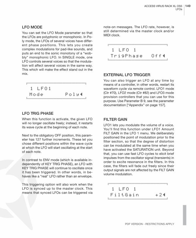
ACCESS VIRUS RACK XL OS5 149LFOs
PDF VERSION - RESTRICTIONS APPLY
LFO MODEYou can set the LFO Mode parameter so thatthe LFOs are polyphonic or monophonic. In Po-ly mode, the LFOs of several voices have differ-ent phase positions. This lets you createcomplex modulations for pad-like sounds, andputs an end to the sonic monotony of a “wob-bly” monophonic LFO. In SINGLE mode, oneLFO controls several voices so that the modula-tion will affect several voices in the same way.This which will make the effect stand out in themix.
01111111111111111112
1 LFO1 Mode Poly≤ 61111111111111111154
LFO TRIG PHASEWhen this function is activate, the given LFOwill no longer oscillate freely; instead, it restartsits wave cycle at the beginning of each note.
Next to the obligatory OFF position, this param-eter has 127 further increments. These let youchose different positions within the wave cycleat which the LFO will start oscillating at the startof each note.
In contrast to ENV mode (which is available in-dependently of KEY TRIG PHASE), an LFO withKEY TRIG PHASE will continue to oscillate onceit has been triggered. In other words, in be-haves like a “real" LFO rather than an envelope.
This triggering option will also work when theLFO is synced up to the master clock. Thismeans that synced LFOs can be triggered via
note-on messages. The LFO rate, however, isstill determined via the master clock and/orMIDI clock.
01111111111111111112
1 LFO 1 TrigPhase Off≤ 61111111111111111154
EXTERNAL LFO TRIGGERYou can also trigger an LFO at any time bymeans of a controller, in other words, restart itswaveform cycle via remote control. LFO1 mode(Ctr #70), LFO2 mode (Ctr #82) and LFO3 modeprovision controllers that you can use for thispurpose. Use Parameter B 9, see the parameterdocumentation [“Appendix” on page 157].
FILTER GAINLFO1 lets you modulate the volume of a voice.You’ll find this function under LFO1 AmountFILT GAIN in the LFO 1 menu. We deliberatelypositioned the point of modulation prior to thefilter section, so that the degree of distortioncan be modulated at the same time when youhave activated the SATURATION unit. Beyondthat, you can use fast LFO cycles to elicit briefimpulses from the oscillator signal (transients) inorder to excite resonance in the filters. In thiscase, the filters will fade out freely since theiroutput signals are not affected by the FILT GAINvolume modulation.
01111111111111111112
1 LFO 1 FiltGain +2≤ 61111111111111111154

150 CHAPTER 12Tips, Tricks& Words Of Wisdom
� VOLUME CONTROL
Next to the Oscillator Volume parameter, the Vi-rus features four other volume stages for everySINGLE or PART:
PATCH VOLUMEVolume level of the sound program. Use PatchVolume to balance out the fundamental differ-ences in levels between the different sound pro-grams. The Patch Volume is stored along withthe sound program. The unit value is 100.
PART VOLUMEVolume level of the MULTI-PART. Use Part Vol-ume to balance out the different levels within aMULTI program. Part Volume is stored alongwith the MULTI program. The unit value is zerosince Part Volume is a bipolar, relative parame-ter.
CHANNEL VOLUMEand ExpressionThese two performance control-lers (Ctr. #7 and #11) can be used in order tomake temporary changes in signal level via asequencer or volume pedal. Like all perform-ance controllers, these are not stored with thesound program. The unit value is 127. A dou-ble-click on the POWER and STORE buttonstogether (Panic function) resets Channel Vol-ume and Expression to this unit value.
� ASSIGN AND THE SOFT KNOBS
The ASSIGN section in the EDIT menu lets youcontrol up to six freely selectable parametersvia up to three modulation sources. The modu-lation sources can be MIDI controllers such asthe modulation wheel as well as internal, voice-related modulation sources such as envelopesand LFOs. In addition, LFO 1 and LFO 2 eachoffer a further, freely selectable modulation des-tination when they’re set to the ASSIGN posi-t ion (use the AMOUNT but tons for th ispurpose).
The obvious thing to do would be to use one ofthe Soft-Knob as a modulation source for oneor several ASSIGN units. However, we deliber-ately chose not to create a direct, fixed link be-tween the Soft Knob and the ASSIGN unitssince, by definition, neither the output of theSoft Knob nor the inputs of the ASSIGN unitshave a fixed controller number.
Instead, you are free to select one of the possi-ble controllers as an ASSIGN source (e.g. themodulation wheel or Controller #12). All youhave to do is enter this controller as the param-eter for the Soft Knob. This configuration isidentical to that of a conventional parameterthat has a dedicated controller number andknob. The knob movements are sent to the se-lected MIDI Out via the selected controller andon to the sequencer where they can be record-ed and sent back to the Virus. Reasonablyenough, you should set the controller numberfor the Soft Knob under Soft Knob Single be-cause this setting (like the ASSIGN settings) isstored with the SINGLE program and doesn’tapply to all SINGLEs (as is the case with theSoft Knob Global setting).
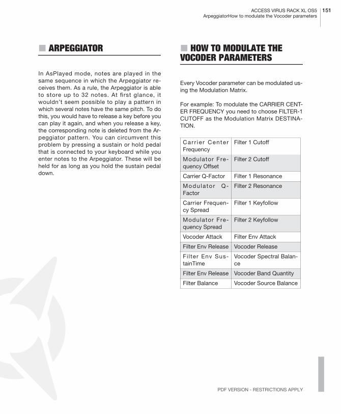
ACCESS VIRUS RACK XL OS5 151ArpeggiatorHow to modulate the Vocoder parameters
PDF VERSION - RESTRICTIONS APPLY
� ARPEGGIATOR
In AsPlayed mode, notes are played in thesame sequence in which the Arpeggiator re-ceives them. As a rule, the Arpeggiator is ableto store up to 32 notes. At first glance, itwouldn’t seem possible to play a pattern inwhich several notes have the same pitch. To dothis, you would have to release a key before youcan play it again, and when you release a key,the corresponding note is deleted from the Ar-peggiator pattern. You can circumvent thisproblem by pressing a sustain or hold pedalthat is connected to your keyboard while youenter notes to the Arpeggiator. These will beheld for as long as you hold the sustain pedaldown.
� HOW TO MODULATE THE VOCODER PARAMETERS
Every Vocoder parameter can be modulated us-ing the Modulation Matrix.
For example: To modulate the CARRIER CENT-ER FREQUENCY you need to choose FILTER-1CUTOFF as the Modulation Matrix DESTINA-TION.
Car r ie r Cente rFrequency
Filter 1 Cutoff
Modulator Fre-quency Offset
Filter 2 Cutoff
Carrier Q-Factor Filter 1 Resonance
Modu la to r Q-Factor
Filter 2 Resonance
Carrier Frequen-cy Spread
Filter 1 Keyfollow
Modulator Fre-quency Spread
Filter 2 Keyfollow
Vocoder Attack Filter Env Attack
Filter Env Release Vocoder Release
Fi l ter Env Sus-tainTime
Vocoder Spectral Balan-ce
Filter Env Release Vocoder Band Quantity
Filter Balance Vocoder Source Balance

152 CHAPTER 12Tips, Tricks& Words Of Wisdom
� MIDI
MIDI DUMP RXThe Virus lets you audition sound banks that areavailable as MIDI dumps on a sequencer indi-vidually rather than loading them directly to thebanks of the Virus, where they would delete thatthe sounds that you have stored there.
Set the MIDI DUMP RX parameter to FORCETO EDIT BUFFER With this option, sounds thatwould otherwise be loaded directly to a soundbank via MIDI are instead loaded to the Editbuffer. The name of the given sound is shown inthe display and can be played straightaway.When additional sounds are sent via MIDI, thesounds that were sent previously are overwrit-ten in the Edit buffer. If you set the tempo of thesequencer that is sending sounds to a veryslow speed, you can load individual sounds andstore them to the desired memory slot bypressing the STORE button.
The two FORCE TO BANK A and “Force ToBank B” options send an incoming sound dumpto the respective bank irrespective of whichbank the sounds were originally stored in.
The VERIFY option compares a MIDI dump tothe memory content of the Virus. It checks if adump was recorded properly on the sequencerand if it can be played back correctly. Load datafrom the sequencer into the Virus while “Verify”is enabled. The Virus’ display will indicate if thedevice is actually receiving data and it will call
your attention to any transmission errors thatmay occur. Data stored in the Virus remains un-affected by this operation.
01111111111111111112
1 MIDI DUMP TX Arrangement≤61111111111111111154
EXPRESSION CONTROLLERThe Virus is able to handle Expression Control-ler (Controller #11) commands. Expression is avolume controller similar to Channel Volumethat can be used independently as a volumecontrol or to create gate effects (Controller #7).It is also reset by Controller Reset (double clickon POWER and STORE). The default setting is127.
BANK/PROGRAM CHANGE VIA SYSEXA bank or program change can be initiated via aSysEx command. These commands are inde-pendent of MIDI channels as well as all otherSysEx parameter changes. SysEx program

ACCESS VIRUS RACK XL OS5 153The Operating System (OS)How to modulate the Vocoder parameters
PDF VERSION - RESTRICTIONS APPLY
changes are always carried out irrespective ofwhether or not the normal program change isdisabled.
PRIORITYThis parameter lets you control how the Vi-rus“steals notes when its polyphonic perform-ance is maxed out. In the first position, "LOW",the voices of all PARTs have the same prioritywhen one voice is switched off to accommo-date a new voice. When you set the Priority of aPART to "High", the Virus will not “steal” anynotes from the voices of this PART. Use this pa-rameter sparingly. In other words, if you set all
Parts to High, you’re defeating the purpose ofthis parameter. In this case, it wouldn’t have anyeffect since the priority of all voices is the same.
01111111111111111112
1 A0 OvertureCK Priority Low≤ 61111111111111111154
� THE OPERATING SYSTEM (OS)
THE 1024 SOUNDS UPDATEThe Virus operating system consists of twoparts. They can be loaded (or "burned") into theVirus separately.
The first part includes the operating system it-self, while the second part carries the 256 ROMsounds (Bank C and D) as well as the dem-osong.
That second part can be replaced by a soundexpansion, so that finally 768 ROM sounds areavailable. The demosong is overwritten by thisprocedure. But you wouldn't need it anymore,we guess. The file with the additional soundscan be found on the CD included, with the filename "SECONDxxx.MID".
You can load this file similar to a operating sys-tem update (see below).
There is no risk to damage the Virus by wrongor corrupted data. The Virus will simply not ac-cept those data.
PART BANK SELECT ( thechange is execut-ed on ly when aprogram changecommand is re-ceived)
F0,00,20,33,01,10,72,pp,1F,vv,F7
PART BANK CHANGE ( thechange is execut-ed immediately)
F0,00,20,33,01,10,72,pp,20,vv,F7
PART PRO-GRAM CHANGE
F0,00,20,33,01,10,72,pp,21,vv,F7
MULTI PRO-GRAM CHANGE
F0,00,20,33,01,10,72,00,69,vv,F7
pp: Part Number from00 to 0F (0 - 15), vv:Program Number from00 to 7F (0-127)

154 CHAPTER 12Tips, Tricks& Words Of Wisdom
INSTALLING AN OPERATING SYSTEM UPDATEPlease don’t try to load a VIRUS b / kb / IndigoOperating System into the rack. We have a spe-cial OS for the Virus rack XL downloadable atour Website.
1 Load the MIDI file into your sequencer andmake sure you have chosen the right MIDIchannel and port settings. The MIDI file con-tains the new software for the Virus, packed inMIDI Sysex data.
2 Ensure that the MIDI clock option is disabled(mixing SysEx data and the MIDI clock can leadto malfunctions of your MIDI interface).
3 Start your sequencer to playback the MIDI-file.
At this stage, you should be able to watch theVIRUS counting up the received blocks. If thedisplay shows ”RECEPTION FAILED,” then atransmission error has occurred. This can becaused by a buffer overrun of the MIDI inter-face. In this case, you will need to upload theentire file again. Lower the tempo of your se-quencer before uploading (e.g. 60 bpm). To pro-ceed, press any key followed by STORE whichwill again enable the receive mode. In case thatthe load procedure simply stops at a certain po-sition, the sequencer you use is not able toplayback the file correctly. In this case, youneed to use another sequencer.
After a successful upload, press STORE to burnthe new operating system into the flash-ROM.Never switch off the VIRUS while burning thedata! Please ensure stable power conditionsduring this procedure which should take ap-proximately 30 seconds. Now, when the Virushas reseted itself, you can use the new operat-ing system!
There’s no danger of a flawed MIDI transmis-sion burning faulty software into the Virus’memory. When the device receives MIDI data,this information is first buffered in the delaymemory of the Virus, where it is checked for er-rors. If the device finds an error, the loading rou-tine is aborted and it will generate an errormessage. Then you can try repeating the proc-ess. The old operating system will remain un-harmed. Only when you actually initiate a burnoperation will the old operating system be de-leted and overwritten with new data.
LOADING THE OS FROM ONE VIRUS TO ANOTHER1 Connect the sending Virus’ (Virus 1) MIDIOut port to the receiving Virus’ (Virus 2) MIDI Inport.
2 Switch on Virus 1 while you’re holding the[Store] button pressed. The display will readSYSTEM UPDATE.
01111111111111111112
SYSTEM UPDATE [STORE] Receive≤ 61111111111111111154
3 Then press the [Value +], [Store], [Store] but-tons in this sequence.
4 Ensure that Virus 2 is connected and thenpress Virus 1’s [Value +] button to launch theoperation.
5 The operating system will be loaded to Virus2. You’ll see that this is the case by the fact theboth devices will indicate high numbers in theirdisplays.
ACCESS VIRUS RACK XL OS5 155The Operating System (OS)How to modulate the Vocoder parameters
PDF VERSION - RESTRICTIONS APPLY
6 Once the loading process is completed,please press [Store] on Virus 2; the software willnow be burned to the Flash Rom.
SOFTWARE UPDATESAccess is known for their policy of free softwareupdates. Simply download the latest Virus op-erating system from our web site and enjoy newVirus features. Maybe you are in need of somefresh sounds? In either way here’s the placeyou’ll find what you need:
http://www.access-music.de

156 CHAPTER 12Tips, Tricks& Words Of Wisdom

Appendix

158 CHAPTER 13Appendix
System Exclusive Data
� SYSTEM EXCLUSIVE IMPLEMENTATION
The Parameters of the VIRUS are organized inthree so-called pages A, B and C. Each pagecontains 128 parameters, addressed by num-bers from 0 to 127. Each parameter is repre-sented by one byte with a maximum value of127. All parameters are individually accessibleby SysEx-Parameterchange.
The pages A and B represent a Single-Program,thus a Single-Program contains 256 Bytes.
Page A (LowPage) contains Single parametersthat are usefull for MIDI automation. The param-eters of this page are additionally controllableby MIDI Control Change. The sending and re-ception of MIDI Control Change can be enabledor disabled by MIDI CONTROL LowPage (CTRLmenu). When disabled (LowPage=SysEx), theVIRUS only sends and receives SysEx Parame-ter Change on Page A. When enabled (Low-Page=Contr), the VIRUS sends MIDI ControlChange on parameter movement, and receivesboth MIDI Control Change and SysEx-Parame-terchange on Page A.
� The default setting is LowPage =Contr.
The remaining Single parameters in Page B(HiPage) are additionally controllable by MIDIPolyphonic Pressure (!). The send and receptionof MIDI Poly Pressure can be enabled or disa-bled by MIDI CONTROL HiPage (CTRL menu).
When disabled (HiPage=SysEx), the VIRUS onlysends and receives SysEx Parameter Changeon Page B. When enabled (HiPage=PolyPrs),the VIRUS sends MIDI Poly Pressure on param-eter movements, and receives both MIDI PolyPressure and SysEx Parameter Change onPage B. This feature should not be used in con-nection with a keyboard that sends PolyphonicPressure.
� The default setting is HiPage=SysEx.
Page C contains Multi parameters and Globalparameters. These parameters are sent and re-ceived only by SysEx Parameter Change.
In the following, all bytes are shown in hexade-cimal representation.
CONTROL CHANGE MESSAGE (ONLY PAGE A)Bc Status byte,
c=MIDI channel nn Parameter Number 0..127
(see parameter list Page A) vv Parameter Value 0..127
see parameter list Page A)
� The Control Change messages are definedas Performance Controller (e.g. ModulationWheel or Hold Pedal) or Sound Parameters (e.g.Cutoff or Patch Volume). The Performance Con-trollers are not stored with a Single-Sound. Ifmore than one Multi Part is set to the same MIDIchannel, all Parts on this MIDI channel receive
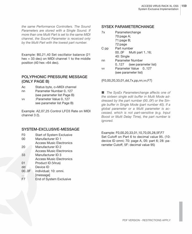
ACCESS VIRUS RACK XL OS5 159System Exclusive Implementation
PDF VERSION - RESTRICTIONS APPLY
the same Performance Controllers. The SoundParameters are stored with a Single Sound. Ifmore than one Multi Part is set to the same MIDIchannel, the Sound Parameter is receiced onlyby the Multi Part with the lowest part number.
Example: B0,21,40 Set oscillator balance (21hex = 33 dec) on MIDI channel 1 to the middleposition (40 hex =64 dec).
POLYPHONIC PRESSURE MESSAGE (ONLY PAGE B)Ac Status byte, c=MIDI channelnn Parameter Number 0..127
(see parameter list Page B)vv :Parameter Value 0..127
see parameter list Page B)
Example: A2,07,25 Control LFO3 Rate on MIDIchannel 3 (!).
SYSTEM-EXCLUSIVE-MESSAGEF0 Start of System Exclusive00 Manufacturer ID 1
Access Music Electronics20 Manufacturer ID 2
Access Music Electronics 33 Manufacturer ID 3
Access Music Electronics 01 Product ID (Virus) dd Device ID00..0F individual; 10: omni. ... [message]F7 End of System Exclusive
SYSEX PARAMETERCHANGE7x Parameterchange
70:page A;71:page B;72:page
C pp Part number00..0F Multi part 1..16;40: Single
nn Parameter Number0..127 (see parameter list)
vv Parameter Value 0..127(see parameter list)
{F0,00,20,33,01,dd,7x,pp,nn,vv,F7}
� The SysEx Parameterchange affects one ofthe sixteen single edit buffer in Multi Mode ad-dressed by the part number (00..0F) or the Sin-gle buffer in Single Mode (part number 40). If aglobal parameter or a Multi parameter is ac-cessed, which is not part-sensitive (e.g. InputBoost or Multi Delay Time), the part number isignored.
Example: F0,00,20,33,01,10,70,05,28,5F,F7 Set Cutoff on Part 6 to decimal value 95. (10:device ID omni; 70: page A, 05: part 6; 28: pa-rameter Cutoff, 5F: decimal value 95)
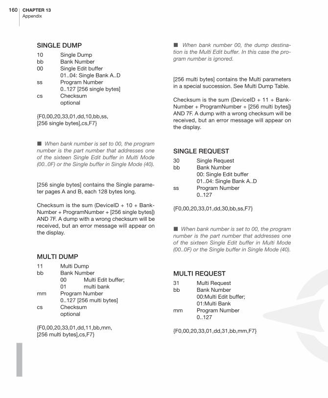
160 CHAPTER 13Appendix
SINGLE DUMP10 Single Dumpbb Bank Number 00 Single Edit buffer
01..04: Single Bank A..Dss Program Number
0..127 [256 single bytes]cs Checksum
optional
{F0,00,20,33,01,dd,10,bb,ss,[256 single bytes],cs,F7}
� When bank number is set to 00, the programnumber is the part number that addresses oneof the sixteen Single Edit buffer in Multi Mode(00..0F) or the Single buffer in Single Mode (40).
[256 single bytes] contains the Single parame-ter pages A and B, each 128 bytes long.
Checksum is the sum (DeviceID + 10 + Bank-Number + ProgramNumber + [256 single bytes])AND 7F. A dump with a wrong checksum will bereceived, but an error message will appear onthe display.
MULTI DUMP11 Multi Dumpbb Bank Number
00 Multi Edit buffer;01 multi bank
mm Program Number0..127 [256 multi bytes]
cs Checksumoptional
{F0,00,20,33,01,dd,11,bb,mm,[256 multi bytes],cs,F7}
� When bank number 00, the dump destina-tion is the Multi Edit buffer. In this case the pro-gram number is ignored.
[256 multi bytes] contains the Multi parametersin a special succession. See Multi Dump Table.
Checksum is the sum (DeviceID + 11 + Bank-Number + ProgramNumber + [256 multi bytes])AND 7F. A dump with a wrong checksum will bereceived, but an error message will appear onthe display.
SINGLE REQUEST30 Single Request bb Bank Number
00: Single Edit buffer01..04: Single Bank A..D
ss Program Number0..127
{F0,00,20,33,01,dd,30,bb,ss,F7}
� When bank number is set to 00, the programnumber is the part number that addresses oneof the sixteen Single Edit buffer in Multi Mode(00..0F) or the Single buffer in Single Mode (40).
MULTI REQUEST31 Multi Requestbb Bank Number
00:Multi Edit buffer;01:Multi Bank
mm Program Number0..127
{F0,00,20,33,01,dd,31,bb,mm,F7}
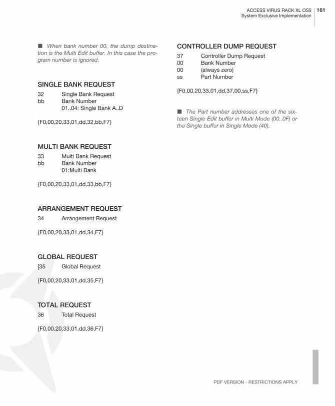
ACCESS VIRUS RACK XL OS5 161System Exclusive Implementation
PDF VERSION - RESTRICTIONS APPLY
� When bank number 00, the dump destina-tion is the Multi Edit buffer. In this case the pro-gram number is ignored.
SINGLE BANK REQUEST32 Single Bank Requestbb Bank Number
01..04: Single Bank A..D
{F0,00,20,33,01,dd,32,bb,F7}
MULTI BANK REQUEST33 Multi Bank Requestbb Bank Number
01:Multi Bank
{F0,00,20,33,01,dd,33,bb,F7}
ARRANGEMENT REQUEST34 Arrangement Request
{F0,00,20,33,01,dd,34,F7}
GLOBAL REQUEST[35 Global Request
{F0,00,20,33,01,dd,35,F7}
TOTAL REQUEST36 Total Request
{F0,00,20,33,01,dd,36,F7}
CONTROLLER DUMP REQUEST37 Controller Dump Request 00 Bank Number00 (always zero)ss Part Number
{F0,00,20,33,01,dd,37,00,ss,F7}
� The Part number addresses one of the six-teen Single Edit buffer in Multi Mode (00..0F) orthe Single buffer in Single Mode (40).
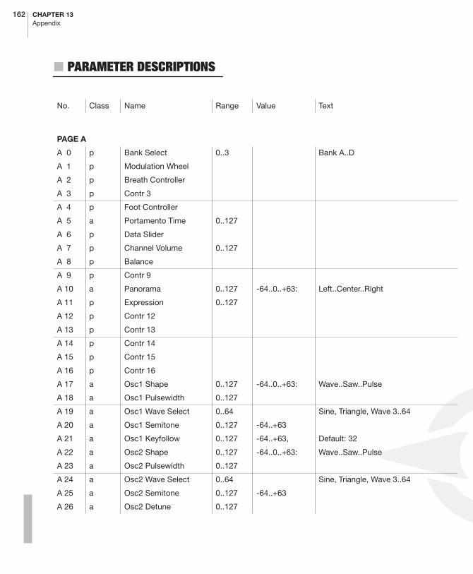
162 CHAPTER 13Appendix
� PARAMETER DESCRIPTIONS
No. Class Name Range Value Text
PAGE A
A 0 p Bank Select 0..3 Bank A..D
A 1 p Modulation Wheel
A 2 p Breath Controller
A 3 p Contr 3
A 4 p Foot Controller
A 5 a Portamento Time 0..127
A 6 p Data Slider
A 7 p Channel Volume 0..127
A 8 p Balance
A 9 p Contr 9
A 10 a Panorama 0..127 -64..0..+63: Left..Center..Right
A 11 p Expression 0..127
A 12 p Contr 12
A 13 p Contr 13
A 14 p Contr 14
A 15 p Contr 15
A 16 p Contr 16
A 17 a Osc1 Shape 0..127 -64..0..+63: Wave..Saw..Pulse
A 18 a Osc1 Pulsewidth 0..127
A 19 a Osc1 Wave Select 0..64 Sine, Triangle, Wave 3..64
A 20 a Osc1 Semitone 0..127 -64..+63
A 21 a Osc1 Keyfollow 0..127 -64..+63, Default: 32
A 22 a Osc2 Shape 0..127 -64..0..+63: Wave..Saw..Pulse
A 23 a Osc2 Pulsewidth 0..127
A 24 a Osc2 Wave Select 0..64 Sine, Triangle, Wave 3..64
A 25 a Osc2 Semitone 0..127 -64..+63
A 26 a Osc2 Detune 0..127

ACCESS VIRUS RACK XL OS5 163Parameter Descriptions
PDF VERSION - RESTRICTIONS APPLY
A 27 a Osc2 FM Amount 0..127
A 28 a Osc2 Sync 0..1 0:Off 1:On
A 29 a Osc2 Filt Env Amt 0..127 -64..+63
A 30 a FM Filt Env Amt 0..127 -64..+63
A 31 a Osc2 Keyfollow 0..127 -64..+63: Default: 32
A 32 p Bank Select 0..3 Bank A..D
A 33 a Osc Balance 0..127 -64..+63:
A 34 a Suboscillator Volume 0..127
A 35 a Suboscillator Shape 0..1 0:Square 1:Triangle
A 36 a Osc Mainvolume 0..127
A 37 a Noise Volume 0..127
A 38 a Ringmodulator Volume 0..127
A 39 a,Vb Noise Color 0..127 -64..0..+63
A 40 a Cutoff 0..127
A 41 a Cutoff2 0..127 -64..+63
A 42 a Filter1 Resonance 0..127
A 43 a Filter2 Resonance 0..127
A 44 a Filter1 Env Amt 0..127
A 45 a Filter2 Env Amt 0..127
A 46 a Filter1 Keyfollow 0..127 -64..+63
A 47 a Filter2 Keyfollow 0..127 -64..+63
A 48 a Filter Balance 0..127 -64..+63
A 49 a Saturation Curve 0..6 0:Off 1:Light 2:Soft 3:Middle 4:Hard5:Digital ..
A 51 a Filter1 Mode 0..3 0:LP 1:HP 2:BP 3:BS
A 52 a Filter2 Mode 0..3 0:LP 1:HP 2:BP 3:BS
A 53 a Filter Routing 0..3 0:Ser4 1:Ser6 2:Par4 3:Split
A 54 a Filter Env Attack 0..127
A 55 a Filter Env Decay 0..127
A 56 a Filter Env Sustain 0..127
A 57 a Filter Env Sustain Time 0..127 -64..+63: Fall..Infinite..Rise
A 58 a Filter Env Release 0..127
No. Class Name Range Value Text
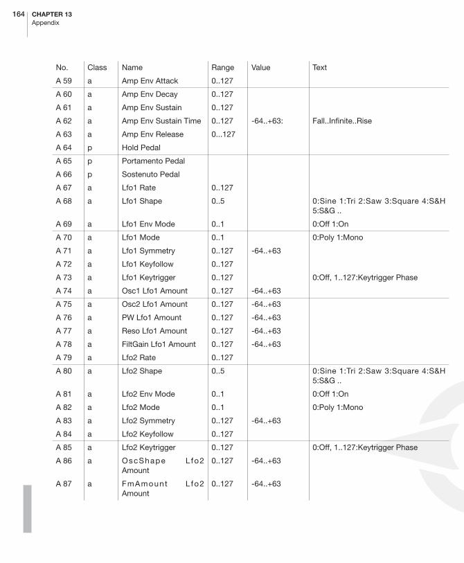
164 CHAPTER 13Appendix
A 59 a Amp Env Attack 0..127
A 60 a Amp Env Decay 0..127
A 61 a Amp Env Sustain 0..127
A 62 a Amp Env Sustain Time 0..127 -64..+63: Fall..Infinite..Rise
A 63 a Amp Env Release 0...127
A 64 p Hold Pedal
A 65 p Portamento Pedal
A 66 p Sostenuto Pedal
A 67 a Lfo1 Rate 0..127
A 68 a Lfo1 Shape 0..5 0:Sine 1:Tri 2:Saw 3:Square 4:S&H5:S&G ..
A 69 a Lfo1 Env Mode 0..1 0:Off 1:On
A 70 a Lfo1 Mode 0..1 0:Poly 1:Mono
A 71 a Lfo1 Symmetry 0..127 -64..+63
A 72 a Lfo1 Keyfollow 0..127
A 73 a Lfo1 Keytrigger 0..127 0:Off, 1..127:Keytrigger Phase
A 74 a Osc1 Lfo1 Amount 0..127 -64..+63
A 75 a Osc2 Lfo1 Amount 0..127 -64..+63
A 76 a PW Lfo1 Amount 0..127 -64..+63
A 77 a Reso Lfo1 Amount 0..127 -64..+63
A 78 a FiltGain Lfo1 Amount 0..127 -64..+63
A 79 a Lfo2 Rate 0..127
A 80 a Lfo2 Shape 0..5 0:Sine 1:Tri 2:Saw 3:Square 4:S&H5:S&G ..
A 81 a Lfo2 Env Mode 0..1 0:Off 1:On
A 82 a Lfo2 Mode 0..1 0:Poly 1:Mono
A 83 a Lfo2 Symmetry 0..127 -64..+63
A 84 a Lfo2 Keyfollow 0..127
A 85 a Lfo2 Keytrigger 0..127 0:Off, 1..127:Keytrigger Phase
A 86 a OscShape L fo2Amount
0..127 -64..+63
A 87 a FmAmount L fo2Amount
0..127 -64..+63
No. Class Name Range Value Text
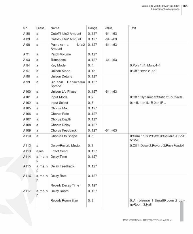
ACCESS VIRUS RACK XL OS5 165Parameter Descriptions
PDF VERSION - RESTRICTIONS APPLY
A 88 a Cutoff1 Lfo2 Amount 0..127 -64..+63
A 89 a Cutoff2 Lfo2 Amount 0..127 -64..+63
A 90 a Panorama L fo2Amount
0..127 -64..+63
A 91 a Patch Volume 0..127
A 93 a Transpose 0..127 -64..+63
A 94 a Key Mode 0..4 0:Poly 1..4: Mono1-4
A 97 a Unison Mode 0..15 0:Off 1:Twin 2..15
A 98 a Unison Detune 0..127
A 99 a Un ison PanoramaSpread
0..127
A100 a Unison Lfo Phase 0..127 -64..+63
A101 a Input Mode 0..2 0:Off 1:Dynamic 2:Static 3:ToEffects
A102 a Input Select 0..8 0:In1L 1:In1L+R 2:In1R ..
A105 a Chorus Mix 0..127
A106 a Chorus Rate 0..127
A107 a Chorus Depth 0..127
A108 a Chorus Delay 0..127
A109 a Chorus Feedback 0..127 -64..+63
A110 a Chorus Lfo Shape 0..5 0:Sine 1:Tri 2:Saw 3:Square 4:S&H5:S&G ..
A112 a Delay/Reverb Mode 0..1 0:Off 1:Delay 2:Reverb 3:Rev+Feedb1
A113 a,ms Effect Send 0..127
A114 a,ms,np
Delay Time 0..127
A115 a,ms,np
Delay Feedback 0..127
A116 a,ms,np
Delay Rate 0..127
Reverb Decay Time 0..127
A117 a,ms,np
Delay Depth 0..127
Reverb Room Size 0..3 0:Ambience 1:SmallRoom 2:Lar-geRoom 3:Hall
No. Class Name Range Value Text

166 CHAPTER 13Appendix
A118 a,ms,np
Delay Lfo Shape 0..5 0:Sine 1:Tri 2:Saw 3:Square 4:S&H5:S&G ..
Reverb Damping 0..127
A119 a,ms,np
Delay Color 0..127 -64..+63
A122 g Keyb Local 0..1 0:Off 1:On
A123 p All Notes Off
No. Class Name Range Value Text
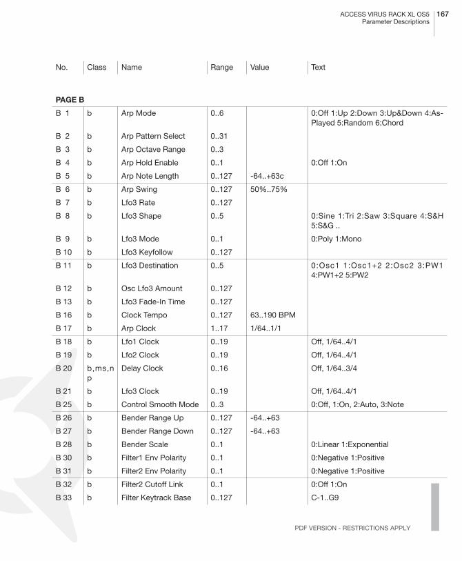
ACCESS VIRUS RACK XL OS5 167Parameter Descriptions
PDF VERSION - RESTRICTIONS APPLY
PAGE B
B 1 b Arp Mode 0..6 0:Off 1:Up 2:Down 3:Up&Down 4:As-Played 5:Random 6:Chord
B 2 b Arp Pattern Select 0..31
B 3 b Arp Octave Range 0..3
B 4 b Arp Hold Enable 0..1 0:Off 1:On
B 5 b Arp Note Length 0..127 -64..+63c
B 6 b Arp Swing 0..127 50%..75%
B 7 b Lfo3 Rate 0..127
B 8 b Lfo3 Shape 0..5 0:Sine 1:Tri 2:Saw 3:Square 4:S&H5:S&G ..
B 9 b Lfo3 Mode 0..1 0:Poly 1:Mono
B 10 b Lfo3 Keyfollow 0..127
B 11 b Lfo3 Destination 0..5 0:Osc1 1:Osc1+2 2:Osc2 3:PW14:PW1+2 5:PW2
B 12 b Osc Lfo3 Amount 0..127
B 13 b Lfo3 Fade-In Time 0..127
B 16 b Clock Tempo 0..127 63..190 BPM
B 17 b Arp Clock 1..17 1/64..1/1
B 18 b Lfo1 Clock 0..19 Off, 1/64..4/1
B 19 b Lfo2 Clock 0..19 Off, 1/64..4/1
B 20 b,ms,np
Delay Clock 0..16 Off, 1/64..3/4
B 21 b Lfo3 Clock 0..19 Off, 1/64..4/1
B 25 b Control Smooth Mode 0..3 0:Off, 1:On, 2:Auto, 3:Note
B 26 b Bender Range Up 0..127 -64..+63
B 27 b Bender Range Down 0..127 -64..+63
B 28 b Bender Scale 0..1 0:Linear 1:Exponential
B 30 b Filter1 Env Polarity 0..1 0:Negative 1:Positive
B 31 b Filter2 Env Polarity 0..1 0:Negative 1:Positive
B 32 b Filter2 Cutoff Link 0..1 0:Off 1:On
B 33 b Filter Keytrack Base 0..127 C-1..G9
No. Class Name Range Value Text

168 CHAPTER 13Appendix
B 34 b,Vb Osc FM Mode 0..12 0:Pos-Tri 1:Tri 2:Wave 3:Noise 4:In L5:In L+R ..
B 35 b Osc Init Phase 0..127 0:Off 1..127
B 36 b Punch Intensity 0..127
B 38 b,Vb Input Follower Mode 0..9 0:Off 1:In L 2:In L+R ...
B 39 b Vocoder Mode 0..12 0:Off 1:Osc 2:OscHold 3:Noise 4:In L5:In L+R ..
B 41 b,Vb Osc3 Mode 0..67 0:Off 1:Osc2Slave 2:Saw 3:Pulse4:Sine 5 Triangle ..
B 42 b,Vb Osc3 Volume 0..127
B 43 b,Vb Osc3 Semitone 0..127 -64..+63
B 44 b,Vb Osc3 Detune 0..127
B 45 b,Vc LowEQ Frequency 0..127
B 46 b,Vc HighEQ Frequency 0..127
B 47 b Osc1 Shape Velocity 0..127 -64..+63
B 48 b Osc2 Shape Velocity 0..127 -64..+63
B 49 b PulseWidth Velocity 0..127 -64..+63
B 50 b Fm Amount Velocity 0..127 -64..+63
B 51 b,Vc Soft Knob1 ShortName See ShortNames Table
B 52 b,Vc Soft Knob2 ShortName See ShortNames Table
B 54 b Filter1 EnvAmt Velocity 0..127 -64..+63
B 55 b Filter1 EnvAmt Velocity 0..127 -64..+63
B 56 b Resonance1 Velocity 0..127 -64..+63
B 57 b Resonance2 Velocity 0..127 -64..+63
B 58 b Second Output Balan-ce
0..127 0:Off 1..127: Front..Center..Rear
B 60 b Amp Velocity 0..127 -64..+63
B 61 b Panorama Velocity 0..127 -64..+63
B 62 b Soft Knob-1 Single see Soft Knob List
B 63 b Soft Knob-2 Single see Soft Knob List
B 64 b Assign1 Source see Assign Sources List
B 65 b Assign1 Destination see Assign Destinations List
B 66 b Assign1 Amount 0..127 -64..+63
No. Class Name Range Value Text

ACCESS VIRUS RACK XL OS5 169Parameter Descriptions
PDF VERSION - RESTRICTIONS APPLY
B 67 b Assign2 Source see Assign Sources List
B 68 b Assign2 Destination1 see Assign Destinations List
B 69 b Assign2 Amount1 0..127 -64..+63
B 70 b Assign2 Destination2 see Assign Destinations List
B 71 b Assign2 Amount2 0..127 -64..+63
B 72 b Assign3 Source see Assign Sources List
B 73 b Assign3 Destination1 see Assign Destinations List
B 74 b Assign3 Amount1 0..127 -64..+63
B 75 b Assign3 Destination2 see Assign Destinations List
B 76 b Assign3 Amount2 0..127 -64..+63
B 77 b Assign3 Destination3 see Assign Destinations List
B 78 b Assign3 Amount3 0..127 -64..+63
B 79 b LFO1 Assign Dest see Assign Destinations List
B 80 b LFO1 Assign Amount 0..127 -64..+63
B 81 b LFO2 Assign Dest see Assign Destinations List
B 82 b LFO2 Assign Amount 0..127 -64..+63
B 84 b,Vb Phaser Mode 0..6 0:Off, 1..6 Phaser Stages
B 85 b,Vb Phaser Mix 0..127
B 86 b,Vb Phaser Rate 0..127
B 87 b,Vb Phaser Depth 0..127
B 88 b,Vb Phaser Frequency 0..127
B 89 b,Vb Phaser Feedback 0..127 -64..+63
B 90 b,Vb Phaser Spread 0..127
B 92 b,Vc MidEQ Gain 0..127 64= 0dB
B 93 b,Vc MidEQ Frequency 0..127
B 94 b,Vc MidEQ Q-Factor 0.127
B 95 b,Vc LowEQ Gain 0..127
B 95 b,Vc HighEQ Gain 0..127
B 97 b,Vb Bass Intensity 0..127
B 98 b,Vb Bass Tune 0..127
B 99 b,Vb Input Ringmodulator 0..127 0:Off 1..127: Direct..Ringmodula-tor..Input
No. Class Name Range Value Text

170 CHAPTER 13Appendix
B100 b,Vb Distortion Curve 0..6 0:Off 1:Light 2:Soft 3:Middle 4:Hard5:Digital ..
B101 b,Vb Distortion Intensity 0..127
B102 b,Vc Assign 4 Source 0..27 see Assign Sources List
B103 b,Vc Assign 4 Destination 0..122 see Assign Destinations List
B104 b,Vc Assign 4 Amount 0..127
B105 b,Vc Assign 5 Source 0..27 see Assign Sources List
B106 b,Vc Assign 5 Destination 0..122 see Assign Destinations List
B107 b,Vc Assign 5 Amount 0..127
B108 b,Vc Assign 6 Source 0..27 see Assign Sources List
B109 b,Vc Assign 6 Destination 0..122 see Assign Destinations List
B110 b,Vc Assign 6 Amount 0..127
B112 b Single Name Char1 32..127 ASCII
B113 b Single Name Char2 32..127 ASCII
B114 b Single Name Char3 32..127 ASCII
B115 b Single Name Char4 32..127 ASCII
B116 b Single Name Char5 32..127 ASCII
B117 b Single Name Char6 32..127 ASCII
B118 b Single Name Char7 32..127 ASCII
B119 b Single Name Char8 32..127 ASCII
B120 b Single Name Char9 32..127 ASCII
B121 b Single Name Char10 32..127 ASCII
B122 b Filter Select 0..2 0:Filt1 1:Filt2 2:Filt1*2
B123 b,Vb Category1
B124 b,Vb Category2
No. Class Name Range Value Text
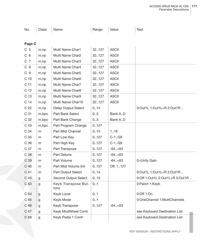
ACCESS VIRUS RACK XL OS5 171Parameter Descriptions
PDF VERSION - RESTRICTIONS APPLY
Page C
C 5 m,np Multi Name Char1 32..127 ASCII
C 6 m,np Multi Name Char2 32..127 ASCII
C 7 m,np Multi Name Char3 32..127 ASCII
C 8 m,np Multi Name Char4 32..127 ASCII
C 9 m,np Multi Name Char5 32..127 ASCII
C 10 m,np Multi Name Char6 32..127 ASCII
C 11 m,np Multi Name Char7 32..127 ASCII
C 12 m,np Multi Name Char8 32..127 ASCII
C 13 m,np Multi Name Char9 32..127 ASCII
C 14 m,np Multi Name Char10 32..127 ASCII
C 22 m,np Delay Output Select 0..14 0:Out1L 1:Out1L+R 2:Out1R ..
C 31 m,bpc Part Bank Select 0..3 Bank A..D
C 32 m,bpc Part Bank Change 0..3 Bank A..D
C 33 m,bpc Part Program Change 0..127
C 34 m Part Midi Channel 0..15 1..16
C 35 m Part Low Key 0..127 C-1..G9
C 36 m Part High Key 0..127 C-1..G9
C 37 m Part Transpose 0..127 -64..+63
C 38 m Part Detune 0..127 -64..+63
C 39 m Part Volume 0..127 -64..+63 0=Unity Gain
C 40 m Part Midi Volume Init 0..127 Off, 1..127
C 41 m Part Output Select 0..14 0:Out1L 1:Out1L+R 2:Out1R ..
C 45 g Second Output Select 0..15 0:Off 1:Out1L 2:Out1L+R 3:Out1R ..
C 63 g Keyb Transpose But-tons
0..1 0:Patch 1:Keyb
C 64 g Keyb Local 0..1 0:Off 1:On
C 65 g Keyb Mode 0..1 0:OneChannel 1:MultiChannels
C 66 g Keyb Transpose 0..127 -64..+63
C 67 g Keyb ModWheel Contr see Keyboard Destination List
C 68 g Keyb Pedal 1 Contr see Keyboard Destination List
No. Class Name Range Value Text
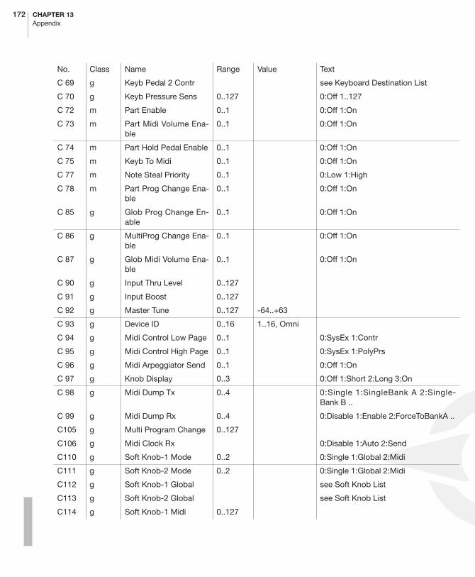
172 CHAPTER 13Appendix
C 69 g Keyb Pedal 2 Contr see Keyboard Destination List
C 70 g Keyb Pressure Sens 0..127 0:Off 1..127
C 72 m Part Enable 0..1 0:Off 1:On
C 73 m Part Midi Volume Ena-ble
0..1 0:Off 1:On
C 74 m Part Hold Pedal Enable 0..1 0:Off 1:On
C 75 m Keyb To Midi 0..1 0:Off 1:On
C 77 m Note Steal Priority 0..1 0:Low 1:High
C 78 m Part Prog Change Ena-ble
0..1 0:Off 1:On
C 85 g Glob Prog Change En-able
0..1 0:Off 1:On
C 86 g MultiProg Change Ena-ble
0..1 0:Off 1:On
C 87 g Glob Midi Volume Ena-ble
0..1 0:Off 1:On
C 90 g Input Thru Level 0..127
C 91 g Input Boost 0..127
C 92 g Master Tune 0..127 -64..+63
C 93 g Device ID 0..16 1..16, Omni
C 94 g Midi Control Low Page 0..1 0:SysEx 1:Contr
C 95 g Midi Control High Page 0..1 0:SysEx 1:PolyPrs
C 96 g Midi Arpeggiator Send 0..1 0:Off 1:On
C 97 g Knob Display 0..3 0:Off 1:Short 2:Long 3:On
C 98 g Midi Dump Tx 0..4 0:Single 1:SingleBank A 2:Single-Bank B ..
C 99 g Midi Dump Rx 0..4 0:Disable 1:Enable 2:ForceToBankA ..
C105 g Multi Program Change 0..127
C106 g Midi Clock Rx 0:Disable 1:Auto 2:Send
C110 g Soft Knob-1 Mode 0..2 0:Single 1:Global 2:Midi
C111 g Soft Knob-2 Mode 0..2 0:Single 1:Global 2:Midi
C112 g Soft Knob-1 Global see Soft Knob List
C113 g Soft Knob-2 Global see Soft Knob List
C114 g Soft Knob-1 Midi 0..127
No. Class Name Range Value Text

ACCESS VIRUS RACK XL OS5 173Parameter Descriptions
PDF VERSION - RESTRICTIONS APPLY
C115 g Soft Knob-2 Midi 0..127
C116 g Expert Mode 0..2 0:0ff 1:On 2:All
C117 g Knob Mode 0..5 0:Off 1:Jump 2:Snap 3:Relative (...)
C118 g Memory Protect 0..1 0:0ff 1:On 2:Warn
C120 g Soft Thru 0..1 0:0ff 1:On
C121 g Panel Destination 0..2 0:Internal 1:Int+Midi 2:Midi
C122 g Play Mode 0..2 0:Single 1:MultiSingle 2:Multi
C123 g Part Number 0..15;40 0..15:Multi Part 1..16; 40:Single Buffer
C124 g Global Channel 0..15 1..16
C125 g Led Mode 0..2 0:Lfo 1:Input 2:Auto ..
C126 g LCD Contrast 0..127
C127 g Master Volume 0..127
No. Class Name Range Value Text
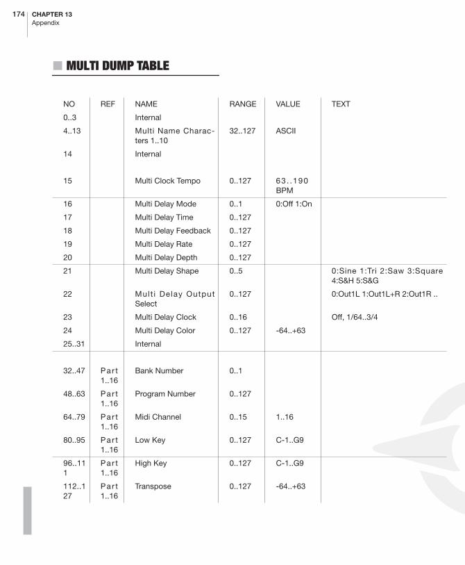
174 CHAPTER 13Appendix
� MULTI DUMP TABLE
NO REF NAME RANGE VALUE TEXT
0..3 Internal
4..13 Multi Name Charac-ters 1..10
32..127 ASCII
14 Internal
15 Multi Clock Tempo 0..127 63 . .190BPM
16 Multi Delay Mode 0..1 0:Off 1:On
17 Multi Delay Time 0..127
18 Multi Delay Feedback 0..127
19 Multi Delay Rate 0..127
20 Multi Delay Depth 0..127
21 Multi Delay Shape 0..5 0:Sine 1:Tri 2:Saw 3:Square4:S&H 5:S&G
22 Mult i Delay OutputSelect
0..127 0:Out1L 1:Out1L+R 2:Out1R ..
23 Multi Delay Clock 0..16 Off, 1/64..3/4
24 Multi Delay Color 0..127 -64..+63
25..31 Internal
32..47 Par t1..16
Bank Number 0..1
48..63 Par t1..16
Program Number 0..127
64..79 Par t1..16
Midi Channel 0..15 1..16
80..95 Par t1..16
Low Key 0..127 C-1..G9
96..111
Par t1..16
High Key 0..127 C-1..G9
112..127
Par t1..16
Transpose 0..127 -64..+63

ACCESS VIRUS RACK XL OS5 175Multi Dump Table
PDF VERSION - RESTRICTIONS APPLY
128..143
Par t1..16
Detune 0..127 -64..+63
144..159
Par t1..16
Part Volume 0..127 -64..+63; 0=Unity Gain
160..175
Par t1..16
Midi Volume Init 0..127 Off, 1..127
176..191
Par t1..16
Output Select 0..14 0:Out1L 1:Out1L+R 2:Out1R ..
192..207
Par t1..16
Effect Send 0..127
208..239
Internal
240..255
Part State Part 1..16 Bitfield (see Part State Bitfield)
NO REF NAME RANGE VALUE TEXT
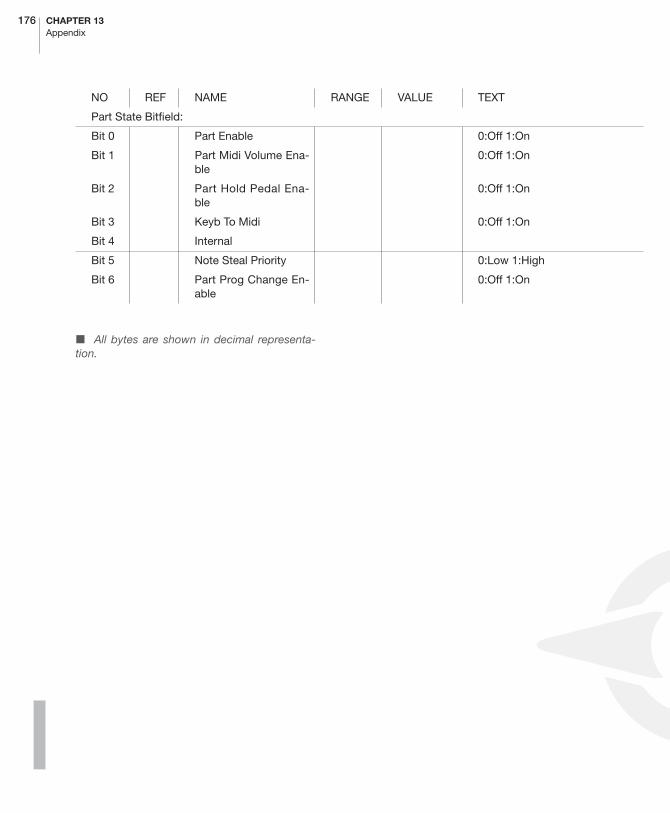
176 CHAPTER 13Appendix
� All bytes are shown in decimal representa-tion.
Part State Bitfield:
Bit 0 Part Enable 0:Off 1:On
Bit 1 Part Midi Volume Ena-ble
0:Off 1:On
Bit 2 Part Hold Pedal Ena-ble
0:Off 1:On
Bit 3 Keyb To Midi 0:Off 1:On
Bit 4 Internal
Bit 5 Note Steal Priority 0:Low 1:High
Bit 6 Part Prog Change En-able
0:Off 1:On
NO REF NAME RANGE VALUE TEXT

ACCESS VIRUS RACK XL OS5 177Classes
PDF VERSION - RESTRICTIONS APPLY
� CLASSES
P: PERFORMANCE CONTROLLER Accessible by Control message. PerformanceControllers are not stored with a Single-Sound.If more than one Multi Part is set to the sameMIDI channel, all Parts on this MIDI channel re-ceive the same Performance Controllers.
A: SOUND PARAMETER OF BANK A Accessible by Control message, SysEx-Param-eterchange and Single-Dump.The Sound Pa-rameters are stored with a Single Sound. Whenreceived as Control Message, the Sound Pa-rameter is received only by the Multi Part withthe lowest part number, if more than one MultiPart is set to the same MIDI channel. When re-ceived as SysEx-Parameterchange or Single-Dump, the part is addressed by the partnumber irrespective of the actual MIDI channelsetting.
B: SOUND PARAMETER OF BANK BAccessible by MIDI Polyphonic Pressure,SysEx-Parameterchange and Single-Dump.TheSound Parameters are stored with a SingleSound. When received as Polyphonic Pressure,the Sound Parameter is received only by theMulti Part with the lowest part number, if morethan one Multi Part is set to the same MIDIchannel. When received as SysEx-Parameter-change or Single-Dump, the part is addressedby the part number irrespective of the actualMIDI channel setting.
M: MULTI PARAMETER Accessible by SysEx-Parameterchange andMulti-Dump The Multi Parameters are storedwith a Multi Patch.
MS: MULTI/SINGLE PARAMETERWhen in Single Mode, the parameter is receivedand stored with the Single Sound.When in MultiMode, the parameter is received and storedwith the Multi Patch. In Multi Mode the SingleSound settings are ignored while the corre-sponding Multi Patch settings are active.
NP: NON-PART-SENSITIVE SOUND PARAMETERWhen in Multi Mode, the parameter affects allMulti Parts.
BPC: BANK/PROGRAM-CHANGE PARAMETER BANK SELECTSelects the Single bank accessed by a subse-quent Program Change, similar to the regularBank Select.Bank Change directly changes theSingle program to the requested bank, withoutchanging the program number. ProgramChange directly changes the Single program tothe requested program number, without chang-ing the bank number; similar to the regular Pro-gram Change. Part number $40 will address theSingle buffer in Single Mode.
G: GLOBAL PARAMETERThe Global Parameters are independent of Sin-gle Sounds or Multi Patches and non-part sen-sitive.
178 CHAPTER 13Appendix
VB: VIRUS C SERIES PARAMETERThese parameters are only available on VIRUSC and VIRUS kc/indigo in Version 3.0 and high-er. VIRUS C parameter changes are ignored byVIRUS a/Virus b series
� On non-part-sensitive parameters the partnumber is ignored, but must still be sent as anyvalue.
� The VIRUS can be switched between MultiMode and Single Mode by parameter C123 PartNumber.
� Remarks for editor/librarian programs Not all256 bytes of a Single or Multi Dump are definedas a parameter. Some of them are defined forinternal use or reserved for future applications.In a bulk dump these byte should not bechanged, they should be sent to the VIRUS onthe same value as they were received in thedump.
� One of the internal parameter (Page A #0) isthe Sound Version Number. On future VIRUSsystem updates new parameters will be de-fined. When the VIRUS receives an older sound,the new parameters will be set to default valuesin the edit buffer and the version number will beupdated automatically. The VIRUS update algo-rithm can be used from outside just by sendinga dump and requesting it back. To prevent in-compatibilites and confusion, the Sound Ver-sion Number should not be changed by anyother device that the VIRUS itself. When soundsare imported into a software library, they shouldbe automatically pathed through the VIRUSfirst, before allowing a change of parameters.Otherwise the VIRUS might reset new parame-ters, when the sound is loaded into the VIRUS,after editing parameters.
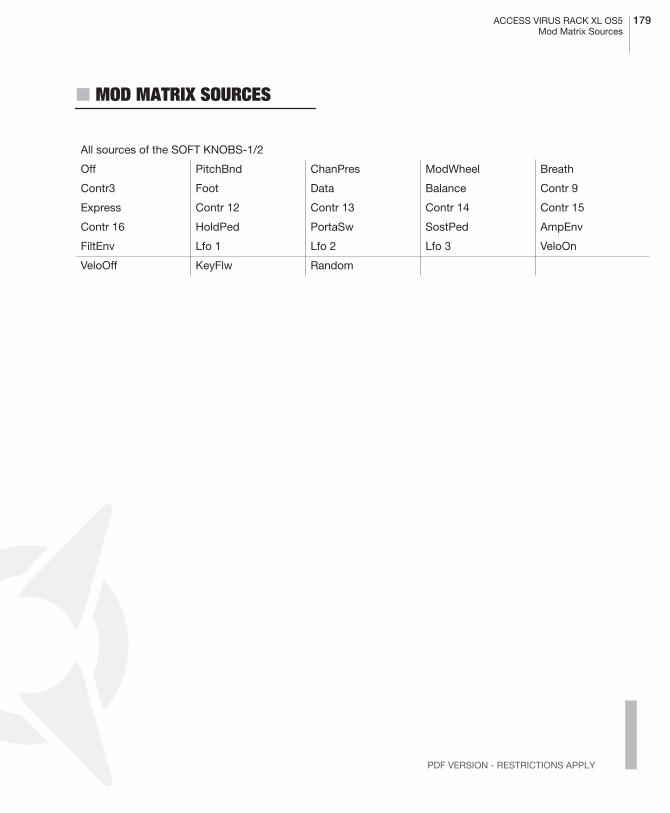
ACCESS VIRUS RACK XL OS5 179Mod Matrix Sources
PDF VERSION - RESTRICTIONS APPLY
� MOD MATRIX SOURCES
All sources of the SOFT KNOBS-1/2
Off PitchBnd ChanPres ModWheel Breath
Contr3 Foot Data Balance Contr 9
Express Contr 12 Contr 13 Contr 14 Contr 15
Contr 16 HoldPed PortaSw SostPed AmpEnv
FiltEnv Lfo 1 Lfo 2 Lfo 3 VeloOn
VeloOff KeyFlw Random

180 CHAPTER 13Appendix
� MOD MATRIX DESTINATIONS
All destinations of the Modulation Matrix
Off PatchVol ChannelVol Panorama Transpose Portamento
Osc1Shape Osc1PlsWdh Osc1WavSel Osc1Pitch Osc1Keyflw Osc2Shape
Osc2PlsWdh Osc2WavSel Osc2Pitch Osc2Detune Osc2FmAmt Osc2EnvAmt
FmEnvAmt Osc2Keyflw OscBalance SubOscVol OscMainVol NoiseVol
Cutoff Cutoff2 Filt1Reso Filt2Reso Flt1EnvAmt Flt2EnvAmt
Flt1Keyflw Flt2Keyflw FltBalance FltAttack FltDecay FltSustain
FltSusTime FltRelease AmpAttack AmpDecay AmpSustain AmpSusTime
AmpRelease Lfo1Rate Lfo1Cont Lfo1>Osc1 Lfo1>Osc2 Lfo1>PlsWd
Lfo1>Reso Lfo1>FltGn Lfo2Rate Lfo2Cont Lfo2>Shape Lfo2>Fm
Lfo2>Cut1 Lfo2>Cut2 Lfo2>Pan Lfo3Rate Lfo3OscAmt UniDetune
UniSpread UniLfoPhs ChorusMix ChorusRate ChorusDpth ChorusDly
ChorusFeed EffectSend DelayTime DelayFeed DelayRate DelayDepth
Osc1ShpVel Osc2ShpVel PlsWhdVel FmAmtVel Flt1EnvVel Flt2EnvVel
Reso1Vel Reso2Vel AmpVel PanVel Ass1Amt1 Ass2Amt1
Ass2Amt2 Ass3Amt1 Ass3Amt2 Ass3Amt3 OscInitPhs PunchInt
RingMod NoiseColor DelayColor ABoostInt ABoostTune DistInt
RingmodMix Osc3Volume Osc3Semi Osc3Detune Lfo1AssAmt Lfo2AssAmt
PhaserMix PhaserRate PhaserDept PhaserFreq PhaserFdbk PhaserSprd
RevbDecay RevDamping RevbColor RevPredely RevFeedbck SecBalance
ArpNoteLen ArpSwing ArpPattern EqMidGain EqMidFreq EqMidQFactor
Assign4Amt Assign5Amt Assign6Amt
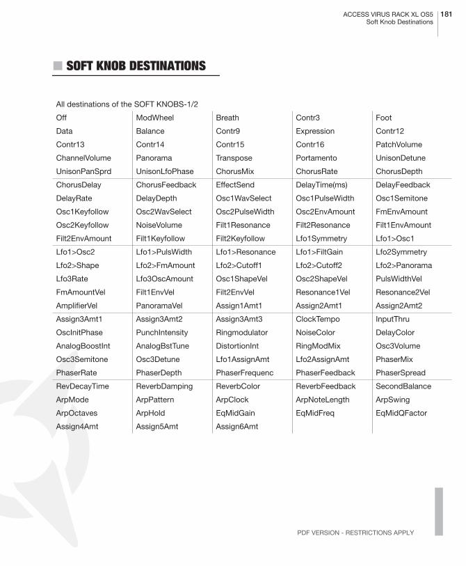
ACCESS VIRUS RACK XL OS5 181Soft Knob Destinations
PDF VERSION - RESTRICTIONS APPLY
� SOFT KNOB DESTINATIONS
All destinations of the SOFT KNOBS-1/2
Off ModWheel Breath Contr3 Foot
Data Balance Contr9 Expression Contr12
Contr13 Contr14 Contr15 Contr16 PatchVolume
ChannelVolume Panorama Transpose Portamento UnisonDetune
UnisonPanSprd UnisonLfoPhase ChorusMix ChorusRate ChorusDepth
ChorusDelay ChorusFeedback EffectSend DelayTime(ms) DelayFeedback
DelayRate DelayDepth Osc1WavSelect Osc1PulseWidth Osc1Semitone
Osc1Keyfollow Osc2WavSelect Osc2PulseWidth Osc2EnvAmount FmEnvAmount
Osc2Keyfollow NoiseVolume Filt1Resonance Filt2Resonance Filt1EnvAmount
Filt2EnvAmount Filt1Keyfollow Filt2Keyfollow Lfo1Symmetry Lfo1>Osc1
Lfo1>Osc2 Lfo1>PulsWidth Lfo1>Resonance Lfo1>FiltGain Lfo2Symmetry
Lfo2>Shape Lfo2>FmAmount Lfo2>Cutoff1 Lfo2>Cutoff2 Lfo2>Panorama
Lfo3Rate Lfo3OscAmount Osc1ShapeVel Osc2ShapeVel PulsWidthVel
FmAmountVel Filt1EnvVel Filt2EnvVel Resonance1Vel Resonance2Vel
AmplifierVel PanoramaVel Assign1Amt1 Assign2Amt1 Assign2Amt2
Assign3Amt1 Assign3Amt2 Assign3Amt3 ClockTempo InputThru
OscInitPhase PunchIntensity Ringmodulator NoiseColor DelayColor
AnalogBoostInt AnalogBstTune DistortionInt RingModMix Osc3Volume
Osc3Semitone Osc3Detune Lfo1AssignAmt Lfo2AssignAmt PhaserMix
PhaserRate PhaserDepth PhaserFrequenc PhaserFeedback PhaserSpread
RevDecayTime ReverbDamping ReverbColor ReverbFeedback SecondBalance
ArpMode ArpPattern ArpClock ArpNoteLength ArpSwing
ArpOctaves ArpHold EqMidGain EqMidFreq EqMidQFactor
Assign4Amt Assign5Amt Assign6Amt
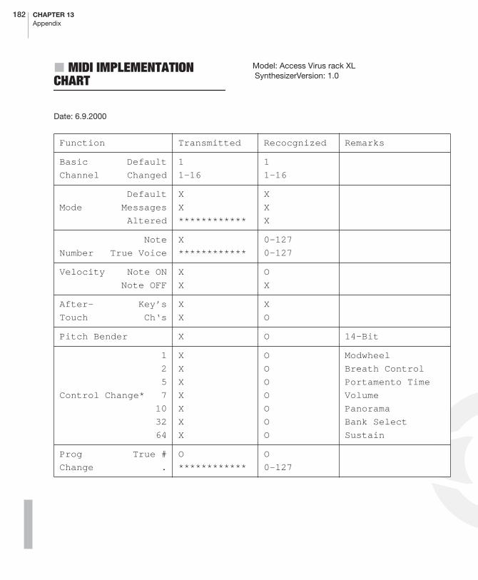
182 CHAPTER 13Appendix
� MIDI IMPLEMENTATION CHART
Date: 6.9.2000
Model: Access Virus rack XL SynthesizerVersion: 1.0
Function Transmitted Recocgnized Remarks
Basic Default
Channel Changed
1
1-16
1
1-16
Default
Mode Messages
Altered
X
X
************
X
X
X
Note
Number True Voice
X
************
0-127
0-127
Velocity Note ON
Note OFF
X
X
O
X
After- Key’s
Touch Ch‘s
X
X
X
O
Pitch Bender X O 14-Bit
1
2
5
Control Change* 7
10
32
64
X
X
X
X
X
X
X
O
O
O
O
O
O
O
Modwheel
Breath Control
Portamento Time
Volume
Panorama
Bank Select
Sustain
Prog True #
Change .
O
************
O
0-127

ACCESS VIRUS RACK XL OS5 183MIDI Implementation Chart
PDF VERSION - RESTRICTIONS APPLY
Mode 1: OMNI ON, POLY Mode 2: OMNI ON, MONO O : Yes
Mode 3: OMNI OFF, POLY Mode 4: OMNI OFF, MONO X : No
System Exclusive O O
System :Song Pos
:Song Sel
Common :Tune .
O
X
X
X
X
X
System :Clock
Realtime :Commands
X
X
X
X
Start, Stop
Continue
Aux- :Local ON/OFF
Mes- :All NotesOff
Sages : ActiveSense
: Reset
X
X
X
X
X
O
O
X
* Note: See MIDI Controller Assignments for more Information.
184 CHAPTER 13Appendix
� FCC INFORMATION (U.S.A)
IMPORTANT NOTICE: DO NOT MODIFY THISUNIT! This product, when installed as indicatedin the instructions contained in this manual,meets FCC requirements. Modifications not ex-pressly approved by ACCESS MUSIC ELEC-TRONICS may void your authority, granted bythe FCC, to use this product.
IMPORTANT: When connecting this product toaccessories and/or another product use onlyhigh quality shielded cables. Cable/s suppliedwith this product MUST be used. Follow all in-stallation instructions. Failure to follow instruc-tions could void your FCC authorisation to usethis product in the USA.
NOTE: This product has been tested and foundto comply with the requirements listed in FCCRegulations, Part 15 for Class „B“ digital devic-es. Compliance with these requirements pro-vides a reasonable level of assurance that youruse of this product in residental environmentwill not result in harmful interference with otherelectronic devices. This equipment generates/uses radio frequencies and, if not installed andused according to the instructions found in theuser manual, may cause interference harmful tothe operation of other electronic devices, Com-pliance with FCC regulations does not guaran-tee that interference wil l not occur in al linstallations. If this product is found to be thesource of interference, which can be determi-nated by turning the unit „OFF“ and „ON“,please try to eliminate the problem by using oneof the following measures:
Relocate either this product or the device that isbeing affected by the interference.
Utilise power outlets that are on branch (Circuitbreaker or fuse) circuits or install AC line filter/s.
In the case of radio or TV interference, relocate/reorient the antenna. If the antenna lead-in is300 ohm ribbon lead, change the lead-in to co-axial type cable.
If these corrective measures do not producesatisfactory results, please contact the local re-tailer authorised to distribute this type of prod-uct.
The statements above apply ONLY to productsdistributed in the USA.
� FCC INFORMATION (CANADA)
The digital section of this apparatus does notexceed the „Class B“ limits for radio noise em-missions from digital apparatus set out in theradio interference regulation of the CanadianDepartment of Communications.
Le present appareil numerique n’emet pas debruit radioelectriques depassant les limites ap-plicables aux appareils numerique de la „ClassB“ prescrites dans la reglement sur le brouillageradioelectrique edicte par le Ministre Des Com-munication du Canada.
This only applies to products distributed inCanada.
Ceci ne s’applique qu’aux produits distribuesdans Canada.

ACCESS VIRUS RACK XL OS5 185Other Standards (Rest of World)
PDF VERSION - RESTRICTIONS APPLY
� OTHER STANDARDS (REST OF WORLD)
This product complies with the radio frequencyinterference requirements of the Council Direc-tive 89/336/EC.
Cet appareil est conforme aux prescriptions dela directive communautaire 89/336/EC.
Dette apparat overholder det gaeldenda EF-di-rektiv vedrorendareadiostoj.
Diese Geräte entsprechen der EG-Richtlinie 89/336/EC.

186 CHAPTER 13Appendix
� DECLARATION OF CONFORMITY
EG-Konformitätserklärung
Für das folgend bezeichnete Erzeugnis/ For thefollowing named product
Access VIRUS SynthesizerModel rack
Wird hiermit bestätigt, daß es den Schutzan-forderungen entspricht, die in der Richtlinie 89/336/FWG des Rates zur Angleichung der Rech-tsvorschriften der Mitgliedstaaten über die ele-ktromagnetische Verträglichkeit festgelegt sind;außerdem entspricht es den Vorschriften desGesetzes über d ie e lekt romagnet ischeVerträglichkeit von Geräten (EMVG) vom 30.August 1995.
Will hereby declared that it conforms to the re-quirements of the Council Directive 89/336/FWG for radio frequency interference. It alsocomplies with the regulations about radio inter-ference of electronic devices dated on August30th, 1995.
Zur Beurteilung des Erzeugnisses hinsichtlichder elektromagnetischen Verträglichkeit wurdenfolgende harmonisierte Normen herangezogen:
The following standards have been used to de-clare conformity:
EM 50 082-1 : 1992 , EN 50 081-1 : 1992 , EN60065 : 1993
Diese Erklärung wird verantwortlich für denHersteller abgegeben:
This declaration has been given responsibly tothe manufacturer:
Access Music ElectronicsTrimburgstraße 1136039 Fulda
Fulda, 16.03.2002
Guido Kirsch, GeschäftsführerGuido Kirsch, Managing Director
Christoph Kemper, GeschäftsführerChristoph Kemper Managing Director
ACCESS VIRUS RACK XL OS5 187Warranty
PDF VERSION - RESTRICTIONS APPLY
� WARRANTY
The access music electronics warranty coversall defects in material and workmanship for aperiod of six months from the date of originalpurchase.
This warranty does not cover defects due toabuse, faulty connections or operation underother than specified conditions.
Warranty coverage is also voided when the de-vice is repaired by unauthorized persons ortampered with in any way.
To ensure the warranty is valid, fill out the war-ranty card completely, including serial no., dateof sale, company stamp, signature of the au-thorized dealer, as well as your name an adressand return it to the adress given below.
If a defect occurs during the warranty period,contact the following adress before sending thedevice:
TSI GMBHSCHLOß AHRENTHAL 53489 SINZIG GERMANYTEL: ++49-2642-9940-0 FAX: [email protected]
The following stipulations also apply:
- Ensure the unit is sent in its original packageor one of equal quality.
- Include a detailed description of the defectand a copy of the purchase receipt.
� MANY THANKS TO
Access would like to thank the following peop-le. The Virus wouldn’t be what it is today wit-hout you!
Ben Crosland, Baeumi, Geoff Farr, Maik Fliege,Thomas Green, Axel Hartmann, Uwe G. Hönig,Jörg Hüttner, Timo Kaluza, Oliver Käser,Shehryar Lasi, Achim Lenzgen, Andrea Mason,Thorsten Matuschowski, Jörg Meißner, PaulNagle, Kai Niggemann, Rob Papen, Matt Pico-ne, Wieland Samolak, Daniela Sauerbier, Ho-ward Scarr, Hans-Jörg Scheffler, Jenny Simon,Matt Skags, Zack Steinkamp, Stephan Vanden-born, Joeri Vankeirsbilck, Jay Vaughan, JensWegerhoff und Daniel Wewer.

188 CHAPTER 13Appendix

Index
190 CHAPTER 14Index
Index
A
ADAPTIVE CONTROL SMOOTHING 138AMPLIFIER ENVELOPE 72ANALOG BOOST 87ARPEGGIATOR 37, 108, 151ARPEGGIATOR CLOCK 110ARPEGGIATOR HOLD 111ARPEGGIATOR MODE 108ARPEGGIATOR NOTE LENGTH 109ARPEGGIATOR OCTAVES 108ARPEGGIATOR PATTERN 108ARPEGGIATOR SEND 124ARPEGGIATOR SWING 110ARRANGEMENT DUMP 122ASSIGN 103, 150ATTACK 72AUDIO INPUTS 51, 145AUDIO ROUTING 53AUDITION FUNCTION 54
B
BAND PASS 21BAND REJECT 21BANK CHANGE 152BEND DOWN 101BEND SCALE 101BEND UP 101BITREDUCER 35
C
CABLE CONNECTIONS 16CARRIER BANK 131CATEGORIES 18, 53CATEGORY 111CHANNEL VOLUME 116, 150
CHANNEL VOLUME RX 116CHORUS 36, 85, 93CHORUS DELAY 85CHORUS DEPTH 85CHORUS DIR/EFF 93CHORUS FEEDBACK 85CHORUS RATE 85CHORUS SHAPE 93CLOCK TEMPO 99COMPARE 47CONTRAST 126CONTROLLER DUMP 122CUTOFF 66, 98CUTOFF LINK 68
D
DATA ENTRY 43DECAY 72DELAY 37, 84, 88DELAY CLOCK 89DELAY COLOR 89DELAY DEPTH 84DELAY FEEDBACK 84DELAY MODE 89DELAY OUTPUT SELECT 90DELAY RATE 84DELAY SHAPE 89DELAY TIME 84DESTINATION 80DETUNE 59, 115DEVICE ID 125DIGITAL 35DISPLAY OF VALUES 46DISTORTION 35, 91DISTORTION INTENSITY 92DISTORTION TYPE 91DUMP 140DYNAMIC 51
E
EDIT BUFFER 42EFFECT SEND 88, 145

ACCESS VIRUS RACK XL OS5 191
PDF VERSION - RESTRICTIONS APPLY
EFFECTS 35, 52ENV AMOUNT 66ENV MODE 77ENV POLARITY 67ENVELOPE 18ENVELOPE FOLLOWER 130EQ HIGH FREQUENCY 94EQ HIGH GAIN 94EQ LOW FREQUENCY 94EQ LOW GAIN 94EQ MID FREQUENCY 94EQ MID GAIN 94EQ MID Q-FACTOR 94EQUALIZER 94EXPRESSION CONTROLLER 152
F
FACTORY SOUNDS 17FILT 1 MODE 67FILT ENV -> FM 62FILT ENV -> PITCH 62FILTER 20, 23FILTER 24 DB 147FILTER BALANCE 68, 147FILTER ENVELOPE 72FILTER GAIN 149FILTER ROUTING 25, 69, 147FILTER SELECT 69FLANGER 36FM 146FM AMOUNT 62FM MODE 62FORCE TO BANK A 123FORCE TO EDIT BUFFER 123
H
HIGH KEY 117HIGH PAGE 125HIGH PASS 21, 35HOLD PEDAL 117
I
INPUT 85, 120INPUT BOOST 121INPUT DIRECT THRU 120INPUT GAIN 121INPUT GLOBAL 52INPUT LEVEL 52INPUT LEVEL INDICATOR 145INPUT MODE 85INPUT PHONO 121INPUT SELECT 86
K
KEY FOLLOW 61, 67, 74KEY MODE 100KEYFOLLOW 62KEYFOLLOW BASE 69KEYRANGE 116KNOB DISPLAY 127KNOB MODE 127
L
LCD CONTRAST 126LFO 30, 74LFO AMOUNT 78LFO CLOCK 77LFO CONTOUR 74, 75LFO ENVELOPE MODE 148LFO EXTERNAL TRIGGER 149LFO KEYFOLLOW 75LFO MODE 77, 149LFO RATE 74, 75LFO SHAPE 74, 75LFO TRIGGER PHASE 149LOW KEY 117LOW PAGE 125LOW PASS 20LOWPASS 35

192 CHAPTER 14Index
M
MASTER CLOCK 50MASTER TUNE 125MASTER VOLUME 98Matrix 103MEMORY PROTECT 125MIDI 122MIDI CHANNEL 114MIDI CHANNEL VOLUME 124MIDI CLOCK 50MIDI CLOCK RX 124MIDI DEVICE ID 125MIDI DUMP RX 122, 152MIDI DUMP TX 122MIDI GLOBAL CHANNEL 123MIDI HIGH PAGE 125MIDI LOW PAGE 125MIDI PANNEL DESTINATION 123MIDI PROGRAM CHANGE 124MIXER 30MOD MATIX 103MOD MATRIX 49MOD MATRIX DESTINATIONS 180MOD MATRIX SOURCES 179MODULATION 21MODULATION TARGETS 31MODULATOR BANK 130MULTI SINGLE MODE 40, 144
N
NOISE 65NOISE COLOR 65NOISE VOLUME 65
O
OS UPDATE 153OSC BAL 64OSC DETUNE 59OSC FM MODE 62OSC MODE 63
OSC PHASE INIT 64OSC SEMITONE 59OSC VOLUME 63OSCILLATOR 27, 28, 58OSCILLATOR SYNC 146OSCILLLATOR VOLUME 52OUTPUT SELECT 114OUTPUTS 53OVERLOAD 145
P
PANIC FUNCTION 54PANORAMA 33, 100PARALLEL 25PARAMETER CONTROL 136PART DETUNE 115PART ENABLE 114PART TRANSPOSE 115PART VOLUME 115, 150PATCH VOLUME 99, 150PHASER 36, 92PHASER DEPTH 92PHASER DIR/EFF 92PHASER FEEDBACK 92PHASER FREQUENCY 92PHASER RATE 92PHASER SPREAD 93PHASER STAGES 93PORTAMENTO 100PRIORITY 116, 153PROGRAM CHANGE 117, 152PULSE WIDTH MODULATION 146PUNCH 103PUNCH INTENSITY 103
R
RANDOM AMOUNT 120RANDOM PAR DEPTH 120RANDOM PATCH GENERATOR 120RANDOM PATCHES 47RATEREDUCER 35RECTIFIER 35
ACCESS VIRUS RACK XL OS5 193
PDF VERSION - RESTRICTIONS APPLY
RELEASE 72, 73RESET 54RESONANCE 66REVERB 37, 82, 88REVERB CLOCK 91REVERB COLOR 90REVERB DAMPING 82REVERB DECAY TIME 82REVERB FEEDBACK 83REVERB MODE 89REVERB OUTPUT SELECT 91REVERB PREDELAY 83REVERB TYPE 90RINGMODULATOR 64
S
SAMPLE&GLIDE 32SAMPLE&HOLD 32SATURATION 23, 147SATURATION CURVE 70SECOND FILE 153SECOND OUTPUT 111SELECT BANK 114SELECT NUMBER 114SEMITONE 58, 59SERIAL-4 25SERIAL-6 25SHAPE 58SMOOTH MODE 101SOFT KNOB DESTNATIONS 181SOFT KNOB GLOBAL 126SOFT KNOB MODE 126SOFT KNOB NAME 126SOFT KNOB SINGLE 126SOFT KNOBS 33, 49, 98, 126, 150, 179, 181SOUNDDIVER 37SPLIT 25STATIC 51STORE 46SUB OSCILLATOR 60SURROUND 111SURROUND BALANCE 111SURROUND SELECT 111SUSTAIN 72, 73
SYNC 61SYSEX 125SYSEX DUMP 140SYSEX IMPLEMENTATION 158SYSEX MULTI DUMP 174SYSEX PARAMETER DESCRIPTION 162SYSTEM MENU 125
T
TIME 72, 73TRANSPOSE 101, 115Trigger Phase 77TUNE 125
U
UNISON 102UNISON DETUNE 102UNISON LFO PHASE 102UNISON MODE 34, 102UNISON PAN SPREAD 102
V
VALUE BUTTONS 144VELOCITY 34VELOCITY FILT 1 ENV AMT 106VELOCITY FILT 2 ENV AMT 107VELOCITY FM AMOUNT 106VELOCITY OSC 1 SHAPE 106VELOCITY OSC 2 SHAPE 106VELOCITY PANORAMA 107VELOCITY PULSE WIDTH 106VELOCITY RESONANCE 1 107VELOCITY RESONANCE 2 107VELOCITY VOLUME 107VERIFY 123VOCODER 94, 130, 151VOCODER ATTACK 96VOCODER BAND QUANTITY 95VOCODER CENTER FREQ 95VOCODER FREQ OFFSET 95VOCODER FREQ SPREAD 95

194 CHAPTER 14Index
VOCODER INPUT SELECT 95VOCODER MODE 94, 131VOCODER Q-FACTOR 96VOCODER SOURCE BALANCE 96VOCODER SPECTRAL BAL 97VOLUME 33, 64, 71, 115
W
WARRANTY 187WAVE 61WAVE SEL/PW 58