Embed Size (px)
Citation preview

© 2019 StrongTM
SR-VERTICAL Rack SeriesFully Assembled Rack with Locking Cover
Package ContentsA. Fully Assembled Rack (1)
B. 5/16” Lag Bolts and Washers (4)
C. Mounting Template (1)
D. Keys - Front Cover (2)
E. #10-32 AV Rack Screws (3U − 12, 5U − 20, 7U − 28)
F. #12-24 IT Rack Screws (3U − 12, 5U − 20, 7U − 28)
G. Accessory Platform (1)
Key Features• Full kit (rack ears and front cover included)
• Arrives fully assembled
• Removable front cover for uninhibited access to equipment during installation and service
• Wire management (knock outs on bottom of rack allow for ample room to manage cables)
• Front door and lid are lockable
• EIA 310-D hole pattern
To ground cabinet, connect the ground wire to the field wiring ground terminal on the bottom panel first. To ground, use UL Listed closed loop connectors with minimum 12 AWG wire 1/4” zinc plated steel or stainless steel internal tooth washer, and an M6 nut.
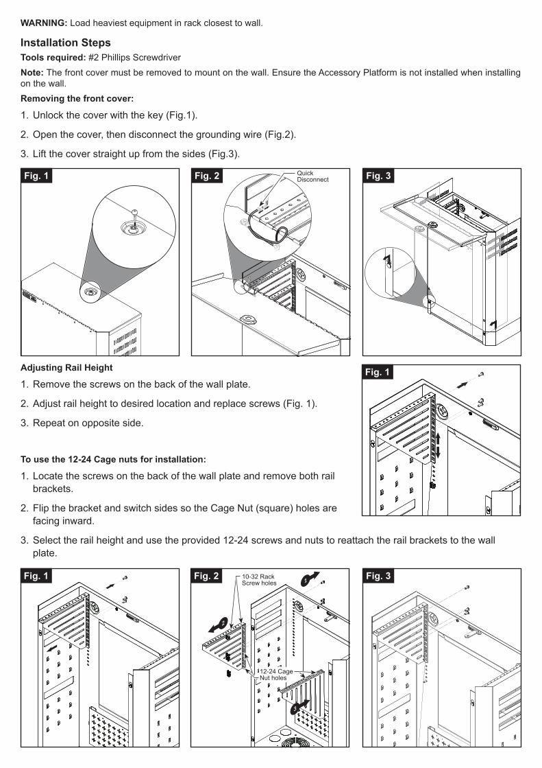
Adjusting Rail Height
1. Remove the screws on the back of the wall plate.
2. Adjust rail height to desired location and replace screws (Fig. 1).
3. Repeat on opposite side.
Installation StepsTools required: #2 Phillips ScrewdriverNote: The front cover must be removed to mount on the wall. Ensure the Accessory Platform is not installed when installing on the wall.Removing the front cover:
1. Unlock the cover with the key (Fig.1).
2. Open the cover, then disconnect the grounding wire (Fig.2).
3. Lift the cover straight up from the sides (Fig.3).
Fig. 3
Fig. 3
Fig. 2
Fig. 2
Fig. 1
Fig. 1
WARNING: Load heaviest equipment in rack closest to wall.
2
1
3
To use the 12-24 Cage nuts for installation:
1. Locate the screws on the back of the wall plate and remove both rail brackets.
2. Flip the bracket and switch sides so the Cage Nut (square) holes are facing inward.
3. Select the rail height and use the provided 12-24 screws and nuts to reattach the rail brackets to the wall plate.
Fig. 1
QuickDisconnect
10-32 Rack Screw holes
12-24 Cage Nut holes

Replacing the Cover:
1. Line up the studs with the key bolts. Insert studs into the keyholes and push the cover down to secure into place (Fig. 1).
2. Reconnect the grounding wire (Fig. 2).
3. Lock the cover using the provided keys (Fig. 3).
Fig. 3Fig. 2Fig. 1
Fig. 3Fig. 2Fig. 1
Platform Attachment and RemovalNote: Ensure lower lag bolts are tightened prior to this step.
1. Locate the key holes on the platform and the studs at the bottom rear of the wall plate to install (Fig. 1).
Note: There are small threaded holes for attaching the WB-300VB-IP-5 (Wattbox).2. Align the top of the keyhole with the stud and slide down to lock in place (Fig. 2).
3. Lift and pull away to remove (Fig 3).
Key Holes
Threaded Holes

Product Max Load Weight A - Height B - Width C - Depth
SR-VERTICAL-3U
150 lb 27.90" 22.70"
6.13"
SR-VERTICAL-5U 9.63"
SR-VERTICAL-7U 13.13"
Note: Welded steel construction with deep black powder coat.
** Ensure that installation is in accordance with ANSI/NFPA 70, National Electrical Code (NEC).
*** Equipment cabinets are intended to house or mount certified equipment that is provided with its own fire and electrical enclosure.
Top
Bottom
Front
Back
Side
A
B
16”
3”
120 mm
C
185∕16"
Dimensions
© 2018 Strong™190109-1610
Lifetime Limited WarrantyAll StrongTM products have a Lifetime Limited Warranty. This warranty includes parts and labor repairs on all components found to be defective in material or workmanship under normal conditions of use. This warranty shall not apply to products that have been abused, modified, or disassembled. Products to be repaired under this warranty must be returned to Strong or a designated service center with prior notification and an assigned return authorization number (RA).
For Technical Support: 1.866.838.5052
Single Keystone
1.25" Conduit Opening