Embed Size (px)
Citation preview

Virtual Shape Definition of Very Low Reynolds
Number Airfoils Using Vortex Shedding
P. Bourdin∗and M.I. Friswell†
University of Bristol, Bristol BS8 1TR, UK
I. Introduction
Over the last decade, aerospace engineers have been challenged to design aircraft that are as smallas possible for special, limited-duration military and civil missions.1 These so-called micro-air vehicles2–4
(MAVs) have become of interest because electronic surveillance and detection sensor equipment can nowadaysbe miniaturised so that the entire payload mass is below 20 grams.1 The advantages of MAVs include low-costproduction, compactness, transportability, rapid deployment, real-time data streaming, and the difficulty tosee, hear, and detect them. Their potential applications cover military reconnaissance, search and rescue,and other missions which could benefit from sensing technology being deployed into a small, cramped area.One way of designing efficient MAVs is by bio-mimetism. Among natural flight systems, large dragonflies(Anisoptera) are capable of carrying out incredible flight manoeuvres.5,6 These include hovering and flightin multiple directions. Even gliding, which is seldom found in the insect world, is part of their flight regime.A small vehicle with the flight capabilities of a dragonfly could therefore execute multiple, dissimilar missionroles at once. While the technology required to enable this is still a long way off, a first step forward isto gain an understanding of the biological dragonfly flying system and to develop methods for mimickingit aerodynamically. In this paper, we focus on the gliding flight regime of the dragonfly with the aim totransfer any beneficial feature into the wing design of fixed-wing MAVs.
Dragonfly wings are not smooth or simple cambered surfaces. Instead, the wing section has a well-definedcorrugated configuration (Figs. 1 and 2). This design is of critical importance to the static aeroelastic stabilityof this ultra-light construction.7 However, from an aerodynamic point of view, this sawtooth single-surfaceairfoil does not appear to be very suitable. The pronounced bends and edges should lead to high dragvalues due to vortex shedding around the sharp corners (more kinetic energy given to the surrounding air).However, in visualizing experiments using profile models, Refs. 8–10 have shown that this geometry inducespositive flow conditions. It has been speculated that eddies shed in the troughs help keep the flow fromseparating. As a matter of fact, Kessel11 claims that “the eddies filling the profile valleys formed by thesebends ‘smooth down’ the profile geometry.” If this is really the case, one can then hope to define a virtualstreamlined shape from a corrugated structure. Moreover, in the context of morphing aircraft,12 where oneseeks to have continuous adjustments in the shape of the wing for more efficient flight control or missionadaptation, the limiting factor is often the skin of the airfoil which must comply with the displacements of theunderlying morphing structure. In the case of virtual airfoil shape, that limitation disappears. The benefitsof virtual shape definition by vortex shedding around a corrugated structure at low Reynolds number aretherefore twofold:
• potential ability to sustain an attached flow (outside the corrugation troughs) at low Reynolds numberswhere conventional airfoil shapes would experience laminar flow separation or large laminar bubbles;
• easier continuous adjustments of the shape for optimal aerodynamics with respect to the current flightcondition.
Our investigation of the corrugated airfoil aerodynamics is conducted in three primary stages. Firstly,numerical simulations of the laminar, transient airflow around the profile lying between the subcosta and the
∗Research Associate, Dept. of Aerospace Engineering.†Professor, Dept. of Aerospace Engineering.
1 of 11
Royal Aeronautical Society
radius of the dragonfly wing (see Figs. 1 and 2) are carried out in order to get a deeper understanding of whathappens in and around the corrugations. For comparison purposes (in terms of aerodynamic performances),the airflow around Mueller’s C4 airfoil (Fig. 3), a wing section shape commonly used in MAV design, iscomputed for the same operating conditions. Secondly, numerical parametric studies are performed withrespect to the Reynolds number, corrugation depth, and camber, to help identify beneficial strategies ofmorphing for flight control and/or mission adaptation. The third and final stage of our investigation isconcerned with the influence of 3D effects on the aerodynamics of low aspect ratio wings at low Reynoldsnumbers, where the wings of interest are lofted with the profiles studied in the first stage (only low aspectratio wings are considered since those are typical for MAVs).
II. Computational Set-Up
A. Numerical Flow Solver
To provide performance estimates, we rely on a cell-centred, finite volume approximation of the time de-pendent Navier-Stokes equations for laminar, incompressible flow. The open-source field operation andmanipulation (OpenFOAM14) C++ class library for continuum mechanics is used for solving the resultingalgebraic equations on a collocated, unstructured grid by means of a projection method, where the PISO algo-rithm15 enables the pressure-velocity coupling between momentum and continuity equations. The followingdiscretisation schemes are selected so as to ensure a global second order accuracy in space and time:
• The time derivative is approximated by a second-order accurate, backward discretisation;
• The convected variables and mass fluxes are interpolated at the cell face centres using second-orderaccurate central discretisation;
• The cell-centre gradients are obtained from a second-order accurate, distance-weighted, least-squaresapproximation;
• The face-centre surface normal gradient is approximated by a second-order accurate central finite differ-ence scheme involving the values at the centroid of the adjacent cells (in the case of non-orthogonalitybetween the adjacent mesh cells, an explicit non-orthogonal correction based on the face-interpolatedcell-centre gradients is performed).
B. Computational Grid Systems
The 2D computational grid system is generated by using Delaunay’s triangulation technique. The outerboundary is located 50 chords away from the airfoil centroid. A uniform spacing of 0.001c, where c is theairfoil chord, is used to discretise the edges forming the airfoil surface. At the investigated chord Reynoldsnumbers (Rec), ranging from 103 to 104, the distance from the airfoil surface to the first off-wall grid pointsis then smaller than c/(6
√Rec), which is more than enough to properly resolve the laminar boundary layer.
Fig. 4 shows the near-field mesh around the dragonfly airfoil and one of its ‘cambered’ versions. To beconsistent with Mueller’s C4 airfoil, the thickness of the linear elements defining the corrugations of thedragonfly wing section represents about 2% of the chord length. One can notice the high density of cells inand around the corrugations. This is done on purpose so as to capture accurately any vortex shedding, whichis the physical phenomenon driving the aerodynamics of the corrugated wing section. The total number ofcells for the baseline 2D grid system is about 105.
The 3D grid system is obtained by generating a 2D triangular mesh of limited extend around the airfoil(i.e. within a box of two-chord length and one-chord height), which is then extruded in the spanwise direction,from the wing root to the wing tip. Tetrahedral elements, along with a pyramid layer to transition from thespanwise prismatic elements, are used to fill the rest of the computational domain, whose far-field boundaryis located 50 chords away from the wing centroid. Since only symmetric flow conditions are investigated,only half the wing is modelled and a symmetry boundary condition is used at the wing root plane. The totalnumber of cells (including prisms, pyramids, and tetrahedra) for the baseline 3D grid system is about 106.
2 of 11
Royal Aeronautical Society

III. Results and Discussion
A. Aerodynamic Properties of the Dragonfly Inner Airfoil
Bidimensional, planar flow simulations around the dragonfly wing section of Fig. 2 and, for comparisonpurposes, Mueller’s C4 airfoil (Fig. 3) have been carried out at several angles of attack, ranging from −5◦ to40◦ (measured with respect to the chord line joining the leading and trailing edges), for a Reynolds numberof 1000, which corresponds to the gliding flight regime of the dragonfly. After a physical time long enoughfor the flow to forget about the initial conditions, each simulation reaches a fully developed state, eithersteady or periodic.
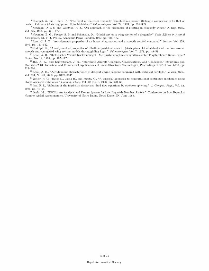
Streamlines around the dragonfly wing section are plotted in Fig. 5. One can notice that the hypothesisof eddies filling the troughs of the corrugation is indeed true. As hypothesised, the eddies ‘smooth’ theshape of the corrugated structure, as the flow pattern outside the corrugation resembles the one around astreamlined body.
When the angle of attack increases (above 10 deg.), vortex shedding becomes more significant, as demon-strated by the instantaneous pressure field from Fig. 6. This makes the flow past the corrugated dragonflyairfoil unsteady, yet periodic, see Fig. 7. Let us mention however that the cambered plate airfoil (Mueller’sC4) exhibits the same kind of unsteadiness (not shown here), indicating that the vortex shedding is more amatter of Reynolds number rather than corrugation.
Fig. 8 compares the drag polar of both the airfoils at Rec = 1000 (plotted values are averages over onevortex shedding period, the horizontal and vertical bars centred about each computed point represent thedrag and lift RMS values). One can see that for lift coefficients greater than 0.5, Mueller’s airfoil is clearlymore efficient than the dragonfly airfoil.
B. Influence of Reynolds Number
It has been observed that increasing the Reynolds number to 5 × 10³ at fixed angle of attack strengthensthe intensity of the free vortices, leading to larger amplitudes in the oscillations of the aerodynamic forces.Increasing the Reynolds number further to 104 triggers significant noise in the time history of the aerodynamiccoefficients (not shown here), suggesting the flow may be transitional at that particular Reynolds number.This has been confirmed with subsequent computations with Xfoil16 for Mueller’s C4 airfoil: Xfoil locatesthe transition at mid-chord on the upper surface at a 10◦ angle of attack for Rec = 104. In the remainder ofthe paper, only Rec = 103 flows are considered.
C. Influence of the Corrugation Trough Depth
The corrugated airfoil geometry from Fig. 2 is scaled up by 1.33% along the vertical direction only (i.e.normal to the chord axis), which gives deeper corrugation troughs. The drag polar of this modified airfoil isplotted for Rec = 103 in Fig. 9, along with the drag polars of the original airfoil and the cambered plate forcomparison purposes (for the sake of clarity, RMS lift and drag values are omitted for the cambered plate)one can observe that the main effect of the modification is to increase the efficiency of the corrugated airfoil(i.e. less drag for the same amount of lift) for lift coefficients greater than 1. The so-modified corrugatedairfoil even becomes better than the simple cambered plate (Mueller’s C4 airfoil) at higher angles of attack,e.g. for lift coefficient greater than 1.5.
D. Effect of Camber Change
In the frame of morphing for mission and/or morphing for control, it is interesting to study how the wingsection aerodynamics changes with an increased camber. In our case, we choose to increase the camber ofthe original dragonfly airfoil by performing two successive deflections: 1) a first deflection about the 4thbend apex, and 2) a second deflection about the 5th bend apex. Fig. 10 depicts the cambered, corrugatedprofiles obtained by applying either two deflections of 10◦ or two of 20◦. Drag polars for these two newconfigurations are plotted in Fig. 11, along with the drag polars of the unmodified corrugated airfoil andMueller’s C4 airfoil (for the sake of clarity, the RMS bars are omitted). As far as the modified corrugatedairfoil featuring two 10◦ deflections is concerned, it offers similar performances as the undeflected modifiedcorrugated airfoil for lift coefficients smaller than 0.5 and greater than 1.5 (with a slight advantage towardsthe undeflected airfoil though); however, for lift coefficients between 0.5 and 1.5, it outperforms significantly
3 of 11
Royal Aeronautical Society

the undeflected airfoil. Furthermore, it performs better as well than Mueller’s C4 airfoil as soon as the liftcoefficient becomes greater than one. Increasing further the camber does not bring additional benefits, onthe contrary it penalises the airfoil at lower lift coefficient because of the extra drag associated with a morepronounced camber (see cambered, modified airfoil #2 in Fig. 11).
E. Three-Dimensional Effects
So far, our investigation assumed two-dimensional planar flow. However, low Reynolds number flows arehighly three-dimensional in essence, which is aggravated by the dragonfly wing geometry itself, where thecorrugation pattern changes from one spanwise station to the other (see Fig. 1). It makes therefore sense toargue that our previous findings based on 2D flow simulations may not hold for a real dragonfly wing, andthat 3D effects could be beneficial (or detrimental) to its aerodynamic performance when compared to theplain cambered plate of finite span. To settle this speculation, we decide to investigate untwisted wings ofsquare planform (i.e. aspect ratio of 1), obtained by extruding either the unmodified corrugated dragonflyprofile or Mueller’s C4 profile. The choice of such a planform is not arbitrary but based on the following twoconsiderations: 1) such a small aspect ratio promotes 3D effects, and 2) MAV wings, which are of interestin this study, have an aspect ratio of the order of 1.
Fig. 12 shows the drag polars predicted for the corrugated wing and the cambered plate, for angles ofattack ranging from 5◦ to 20◦ with 5◦ increments. In contrast with the 2D cases, the unsteadiness of theflow past the square wings is not very pronounced, even for angles of attack greater than 10◦. In fact, onlythe corrugated wing shows some noticeable unsteadiness at 20◦ angle of attack, but not as much as in the2D case though. In the like of the 2D cases, the corrugated wing based on the unmodified dragonfly wingsection is outperformed by the simple cambered plate which can reach higher lift coefficients, and produceless drag for the same lift. In that respect, we can say that the corrugated structure aerodynamics does notbenefit, as it was hoped, from 3D effects.
IV. Conclusion
We investigated the aerodynamics of the inner wing section of a dragonfly forewing and compared itsperformance in the gliding flight regime to a thin, circular-arc airfoil. It appeared, from two- and three-dimensional simulations that the latter outperforms the dragonfly wing section. However, adding somecamber to the original dragonfly wing section and deepening the trough of its corrugations made it superior tothe cambered plate for moderate to high angles of attack. Considering the fact that the dragonfly wing sectionshape we studied was extracted from an unloaded, dry wing, it is reasonable to assume that the shape of sucha membrane wing will be quite different when loaded. Therefore the predicted performance of the unmodifiedunloaded shape are not very indicative of the real potential of a dragonfly wing section. Nevertheless, wedemonstrated that, by applying elementary deformations to such a wing, better performances could beattained and that they could match those of a typical thin airfoil used in MAV design. Whether thesedeformations are the same or not as the ones undergone by the real membrane wing of the dragonfly remainsan open question though.
V. Acknowledgements
This work has been supported by a Marie Curie excellence research grant funded by the EuropeanCommission.
References
1Mueller, T. J., “Aerodynamic Measurements at Low Reynolds Numbers for Fixed Wing Micro-Air Vehicles,” presentedat the RTO AVT/VKI Special course on Development and Operation of UAVs for Military and Civil Applications, September13–17, 1999, VKI, Belgium.
2Ashley, S., “Palm-Size Spy Planes,” Mechanical Engineering, February 1998, pp. 74–78.3Davis, W. R. Jr., Kosicki, B. B., Boroson, D. M., and Kostishack, D. F., “Micro Air Vehicles for Optical Surveillance,”
The Lincoln Laboratory Journal, Vol. 9, No. 2, 1996, pp. 197–213.4Wilson, J. R., “Mini Technologies for Major Impact,” Aerospace America, May 1998, pp. 36–42.5Rueppel, G., “Kinematic analysis of symmetrical flight manoeuvres of Odonata,” J. Exp. Biol., Vol. 144, 1989, pp. 13–42.
4 of 11
Royal Aeronautical Society
6Rueppel, G. and Hilfert, D., “The flight of the relict dragonfly Epiophlebia superstes (Selys) in comparison with that ofmodern Odonata (Anisozygoptera: Epiophlebiidae),” Odonatologica, Vol. 22, 1993, pp. 295–309.
7Newman, D. J. S. and Wootton, R. J., “An approach to the mechanics of pleating in dragonfly wings,” J. Exp. Biol.,Vol. 125, 1986, pp. 361–372.
8Newman, B. G., Savage, S. B. and Schouella, D., “Model test on a wing section of a dragonfly,” Scale Effects in AnimalLocomotion, ed. T. J. Pedley, Academic Press, London, 1977, pp. 445–477.
9Rees, C. J. C., “Aerodynamic properties of an insect wing section and a smooth aerofoil compared,” Nature, Vol. 258,1975, pp. 141–142.
10Rudolph, R., “Aerodynamical properties of Libellula quadrimaculata L. (Anisoptera: Libellulidae) and the flow aroundsmooth and corrugated wing section models during gliding flight,” Odonatologica, Vol. 7, 1978, pp. 49–58.
11Kesel, A. B., “Biologisches Vorbild Insektenfluegel – Mehrkriterienoptimierung ultraleichter Tragfluechen,” Biona ReportSeries, No. 12, 1998, pp. 107–117.
12Jha, A. K., and KudvaSmart, J. N., “Morphing Aircraft Concepts, Classifications, and Challenges,” Structures andMaterials 2004: Industrial and Commercial Applications of Smart Structures Technologies, Proceedings of SPIE, Vol. 5388, pp.213–224.
13Kesel, A. B., “Aerodynamic characteristics of dragonfly wing sections compared with technical aerofoils,” J. Exp. Biol.,Vol. 203, No. 20, 2000, pp. 3125–3135.
14Weller, H. G., Tabor G., Jasak H., and Fureby C., “A tensorial approach to computational continuum mechanics usingobject-oriented techniques,” Comput. Phys., Vol. 12, No. 6, 1998, pp. 620–631.
15Issa, R. I., “Solution of the implicitly discretized fluid flow equations by operator-splitting,” J. Comput. Phys., Vol. 62,1986, pp. 40–65.
16Drela, M., “XFOIL: An Analysis and Design System for Low Reynolds Number Airfoils,” Conference on Low ReynoldsNumber Airfoil Aerodynamics, University of Notre Dame, Notre Dame, IN, June 1989.
5 of 11
Royal Aeronautical Society

Figure 1. Drawing of a dragonfly forewing (Aeshnacyanea) with wing sections shown below at 0.3lrel,0.5lrel and 0.7lrel, where lrel denotes the wingspan.C, costa; SC, subcosta; R, radius; N, nodus; M,mediana 1. Taken from Ref. 13.
Figure 2. Wing section profile of a dragonflyforewing at 30% wingspan.
Figure 3. Mueller’s C4 airfoil, a 1.93% thick, cam-bered plate with tapered trailing edge and circulararc shape of 4% camber (from Ref. 1).
Figure 4. Computational grids around original (left) and morphed (right) dragonfly airfoils.
6 of 11
Royal Aeronautical Society
Figure 5. Streamlines around the airfoil forepart at 0 deg angle of attack and Re=1000.
7 of 11
Royal Aeronautical Society

(a) t/T = 0 (b) t/T = 0.17
(c) t/T = 0.33 (d) t/T = 0.50
(e) t/T = 0.67 (f) t/T = 0.83
Figure 6. Contours of the pressure coefficient at different instants over a vortex shedding period (α = 10◦;Re=1000; period T is 1.2c/U , where U is the freestream velocity).
8 of 11
Royal Aeronautical Society
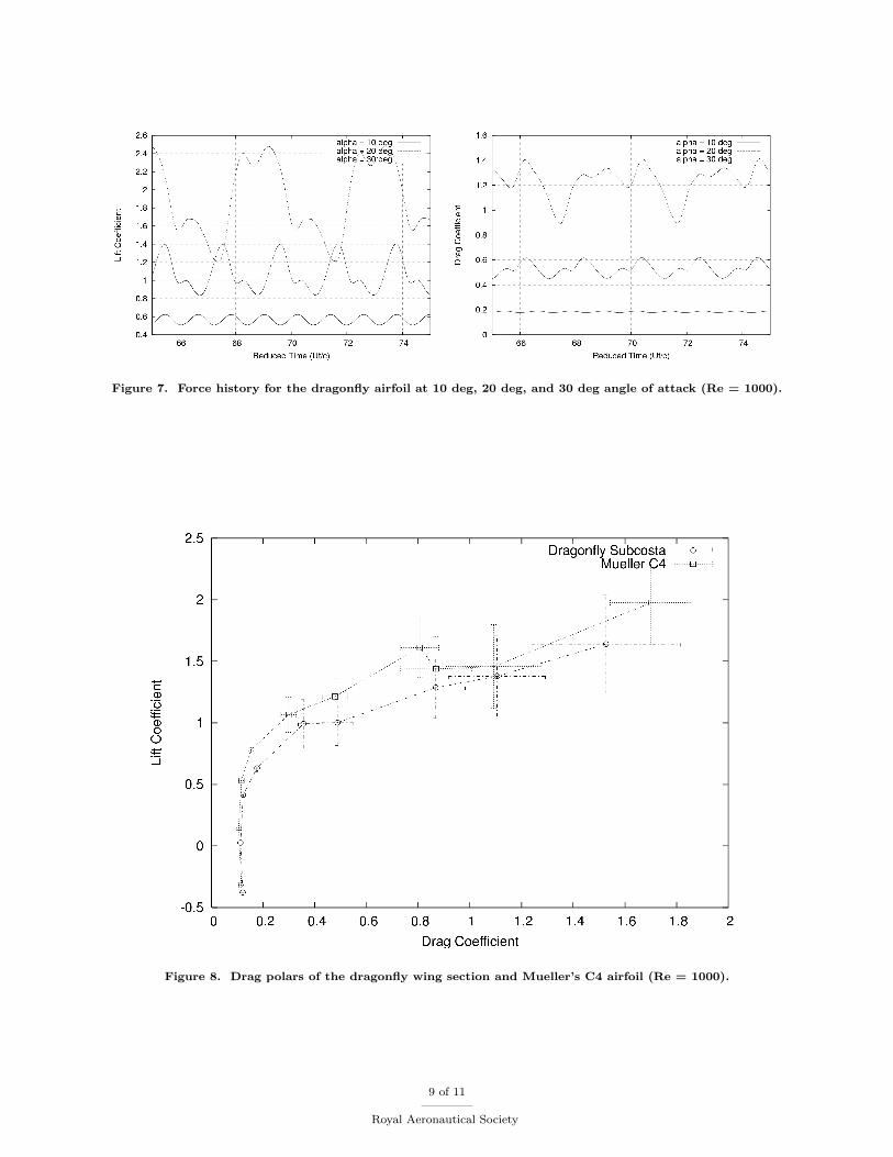
Figure 7. Force history for the dragonfly airfoil at 10 deg, 20 deg, and 30 deg angle of attack (Re = 1000).
Figure 8. Drag polars of the dragonfly wing section and Mueller’s C4 airfoil (Re = 1000).
9 of 11
Royal Aeronautical Society

Figure 9. Drag polars of Mueller’s C4 airfoil, the original dragonfly wing section, and the modified dragonflywing section (Re = 1000).
Figure 10. Geometries of the modified dragonfly wing sections.
10 of 11
Royal Aeronautical Society

Figure 11. Drag polars of Mueller’s C4 airfoil and the modified dragonfly wing sections (Re = 1000). ‘Modifiedairfoil’ refers to the uncambered airfoil with 1.33% deeper corrugation troughs; ‘modified, cambered airfoil #1’refers to the modified airfoil after 2 deflections of 10◦; and finally ‘modified, cambered airfoil #1’ refers to themodified airfoil after 2 deflections of 20◦.
Figure 12. Drag polars for the square cambered plate (Mueller’s C4) and the square corrugated plate (dragonflywing section) at Re = 1000.
11 of 11
Royal Aeronautical Society