Embed Size (px)
Citation preview

1
Virtual Connect and HP A-Series switches IRF Integration
Guide
Technical white paper
Feedback: [email protected]
Table of contents
Introduction ......................................................................................................................................... 2 IRF and Virtual Connect setup configurations ....................................................................................... 2 Failover tests .................................................................................................................................... 2 Images of IMC (Intelligent Management Center) and Insight Control for vCenter network monitoring .......... 2
Design scenarios ................................................................................................................................. 3
Network topology ................................................................................................................................ 5 Physical diagram ............................................................................................................................. 5 Logical diagram ............................................................................................................................... 6
IRF and MAD technology overview ........................................................................................................ 7 IRF (Intelligent Resilient Framework) .................................................................................................... 7 MAD (Multi-Active Detection) ............................................................................................................. 8
IRF and Virtual Connect setup configurations ......................................................................................... 10 Quick CLI reference table ................................................................................................................ 10 A5820 switch: Convert standalone switches to IRF logical switch ......................................................... 11 A5820: BFD MAD configuration ...................................................................................................... 14 A5820: LLDP ................................................................................................................................. 15 Flex-10: LLDP ................................................................................................................................. 16 A5820: LACP ................................................................................................................................ 17 Flex-10: LACP ................................................................................................................................ 19 Flex-10: Server Profile ..................................................................................................................... 21 ESXi configuration .......................................................................................................................... 22
Failover tests ..................................................................................................................................... 23 Uplink failure ................................................................................................................................. 23 Switch failure ................................................................................................................................. 26 IRF link failure ................................................................................................................................ 28 Virtual Connect module failure ......................................................................................................... 31
Insight Control for Vmware vCenter monitoring ..................................................................................... 33
IMC network management .................................................................................................................. 36
Appendix 1: A5820 logical switch IRF configuration ............................................................................. 39
Appendix 2: Design 3 running status .................................................................................................. 44
Acronyms ......................................................................................................................................... 45

2
Introduction
Intelligent Resilient Framework (IRF) is an innovative HP switch platform virtualization technology that
allows dramatic simplification of the design and operations of data center and campus Ethernet
networks. IRF overcomes the limitations of traditional STP (Spanning Tree Protocol) based and legacy
competitive designs by delivering new levels of network performance and resiliency.
Virtual Connect is an industry standard-based implementation of server-edge virtualization. It cleanly
separates server enclosure administration from LAN and SAN administration and allows you to add,
move, or replace servers without impacting production LAN and SAN availability
This document provides detailed configuration and test information for the following items: (Please
note, although A5820 was chosen as the platform of testing but IRF design concept should remain the
same for other A-series switches)
IRF and Virtual Connect setup configurations
A5820/5800 logical switch and IRF link setup from two standalone switches (on page
11)
A5820/5800 BFD MAD (Multi-Active Detection) link setup (on page 14)
LLDP neighbor discovering (on page 15)
LACP port bundling (long timeout and short timeout) (on page 17)
Failover tests
A5820 port-channel (Bridge Aggregation Interface connecting to Virtual Connect) failure
(on page 23)
A5820 switch failure (on page 26)
A5820 IRF link failure to test MAD detection (on page 28)
Virtual Connect primary module failure (on page 31)
Images of IMC (Intelligent Management Center) and Insight Control for
vCenter network monitoring
IC (Insight Control) for VMware vCenter plug-in screen capture of network monitoring of
Virtual Connect, vSwitch, and Access switch (A5820) (on page 33)
HP Networking IMC screen capture of A5820 and Virtual Connect monitoring (on page
36)

3
Design scenarios
Two typical design scenarios are available to connect Virtual Connect with network switches.
A common misunderstanding people tend to have when connecting Virtual Connect with IRF or Cisco
vPC/VSS switches is described in the following page. The design does not work.
The above concepts apply to all Virtual Connect models providing ethernet connectivity, which
include VC 1/10-F, VC Flex-10 and VC Flexfabric modules.
Scenario 1—This is a typical connection scenario, in
which Virtual Connect modules connect with non-
IRF/vPC/VSS capable switches.
Virtual Connect needs to configure one SUS (Shared
Uplink Set) per Virtual Connect module (two total).
Switch 1 and switch 2 each have one port channel
configured to peer with Virtual Connect SUS.
Scenario 2—This is the recommended connection scenario,
in which Virtual Connect modules connect with
IRF/vPC/VSS logical switch.
Virtual Connect needs to configure one SUS per Virtual
Connect module (two total). The logical switch also has two
port channels configured to peer with Virtual Connect SUS,
which is known as Active/Active Virtual Connect design.
Active/Standby Virtual Connect design is also available,
but because it does not use all available uplink bandwidth,
it is not discussed here in more detail. For more information
on Active/Standby design, see scenario1:4 in the HP
Virtual Connect Ethernet Cookbook
(http://h20000.www2.hp.com/bc/docs/support/Support
Manual/c01990371/c01990371.pdf).
This design provides two main benefits over the previous
design:
If either switch fails, traffic remains on the same port
channel and rehashes to the remaining physical link in
less than one second. The server does not require failover
tests.
For the incoming traffic from upstream core switch to
server direction, all traffic can be sent to Virtual Connect.
Previously, if the destination MAC (media access control)
was on the other switch, the traffic would have to
traverse the inter-switch trunk, so the flow was not
optimized.

4
Scenario 3—This configuration does not work. Configuring one port channel on a logical switch side and one SUS
on a Virtual Connect side does not move traffic forward on all four links. Virtual Connect does not support port
channels across different modules. Some links will go into standby and not form port channels.
See Appendix 2 (on page 44) for the results of this scenario.

5
Network topology
Physical diagram
The IRF cluster consists of one A5820 switch and one A5800-32C switch. Comware software
supports IRF clustering on different switch models if they are compatible with each other for IRF.
The A5820 and A5800 switches form an IRF bundle link between them with two 10G links. The
A5820 switch is switch 1, the master of the domain, and has logical port IRF-Port2. The A5800
switch is switch 2, the slave of the domain, and has logical port IRF-Port1, defined originally before
merging with the A5820 switch.
The A5820 and A5800 switches use one Gigabit Ethernet link as a BFD MAD link for MAD.
VC1 and VC2 are Flex-10 modules in interconnect bays 1 and 2 of the HP BladeSystem c7000
Enclosure. Each Flex-10 module has a SUS connecting to an IRF virtual device. A SUS consists of two
10G links terminated on A5820 and A5800 switches. With IRF, these two 10G links form one
bridge-aggregation bundle (the same as port channel on Cisco NX-OS and etherchannel on Cisco
IOS). VC1 connects the IRF cluster with the Bridge-Aggregation 2 interface, and VC2 connects the IRF
cluster with the Bridge-Aggregation 3 interface. Bridge-Aggregation 1 forms a virtual port channel

6
between the IRF cluster and the virtual machine’s default gateway (simulated by an HP E-Series
switch).
Traffic flow testing uses ping packets from VM1 (192.168.1.178) to its default gateway
(192.168.1.1). The VM traffic has two paths to reach its default gateway, depending on how the
vSwitch hashes VM traffic to a specific vmnic.
Logical diagram
Two bundle interfaces (Bridge-Aggregation 2 and Bridge-Aggregation 3) exist between the Virtual
Connect and the IRF logical switch because Virtual Connect currently does not support link bundling
across two different physical modules.

7
IRF and MAD technology overview
IRF (Intelligent Resilient Framework)
IRF IRF creates one logical switch from two or more physical switches. The A5820 switch
can support up to nine switches in one IRF domain.
The logical switch uses standard LACP to connect to any vendor, core, distribution,
or edge switches with a failure convergence time of less than 40 milliseconds. The
switch acts as the following:
Single IP address for management
Single layer 2 switch
Single layer 3 router (all protocols)
Implementation is available across multiple products from core to access platforms
A12500, A10500 A9500, A7500, A5820, A5800, and A5500 series switches.
With IRF technology, the network is transformed as shown in the following diagram.
Role Member switches form an IRF virtual device. Each of them performs one of the
following two roles:
Master—manages the IRF virtual device
Subordinate—members that are backups of the master
If the master fails, the IRF virtual device automatically elects a new master from one
of the subordinates. Masters and subordinates are elected through the role election
mechanism. An IRF virtual device has only one master at a time.
IRF port An IRF port is a logical port dedicated to the internal connection of an IRF virtual
device. An IRF port can be numbered as IRF-port1 or IRF-port2. An IRF port is
effective only after it is bound to a physical port.
Important:
An IRF-Port1 on one device can only be connected to the physical port bound to the
IRF-Port2 of a neighboring device; otherwise, an IRF virtual device cannot be formed.

8
Physical
IRF port
Physical IRF ports are physical (copper or fiber) ports bound to an IRF port. They
perform the following functions:
Connect IRF member switches
Forward IRF protocol packets and data packets between IRF member switches
Priority Member priority determines the role of a member during a role election process. A
member with a higher priority is more likely to be a master. The priority of a switch
defaults to 1.
Member ID An IRF virtual device uses member IDs to uniquely identify its members. Configuration
Information such as port (physical or logical) numbers, port configurations, and
member priorities relate to member IDs.
Domain ID Each switch belongs to one IRF domain. By default, the domain ID is 0. Although
switches with different domain IDs can form an IRF virtual device, HP recommends
assigning the same domain ID to the members of the same IRF virtual device.
Otherwise, the LACP MAD detection cannot function properly.
MAD (Multi-Active Detection)
MAD MAD protects IRF link failure when both switches with the same configuration meet the
criteria for master switch. In this case, MAD shuts down one of the switches according to
role election. The switch with a higher priority becomes the master, and then the local
interfaces for switch 2 are shut down.
When an IRF link is down as a result of MAD, switch 1 continues to run. Switch 2 inactivates
all local interfaces.
MAD detects multiple active IRFs using one of three methods:
LACP
BFD
ARP
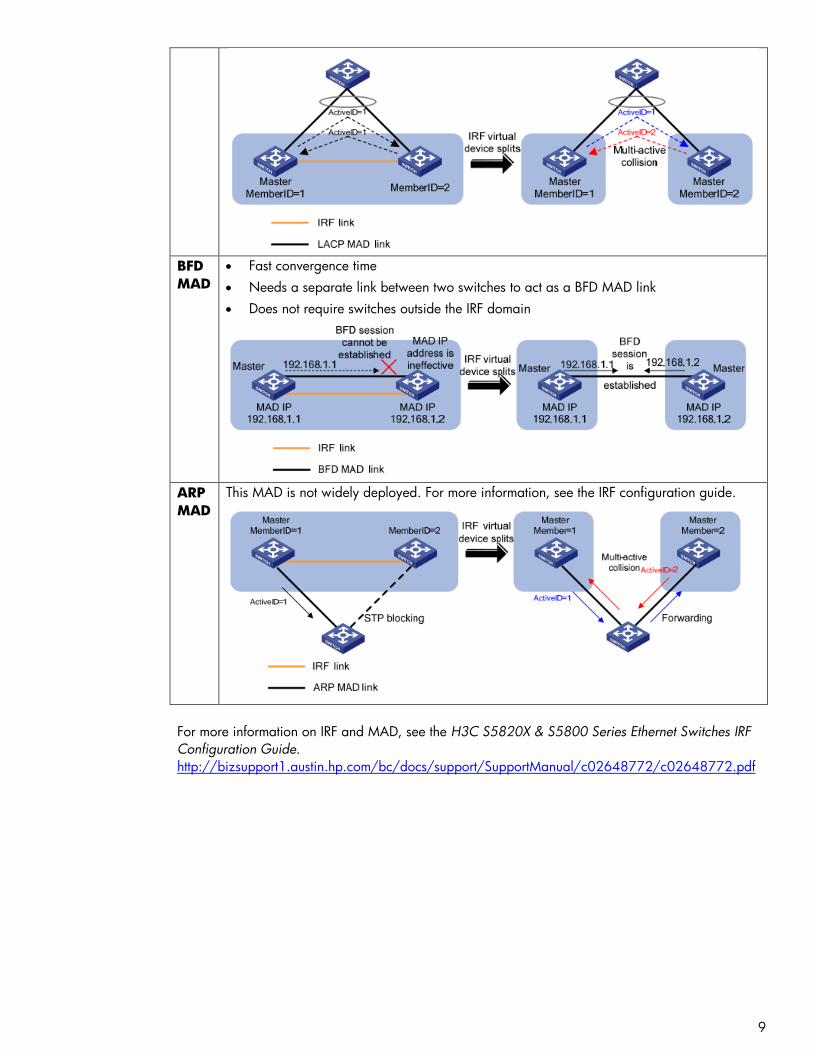
LACP
MAD
Most widely deployed
Fastest convergence time
Needs only one CLI “MAD enable” under bridge aggregation interface
Needs a third switch (Typically HPN A-series) to understand extended LACPDU (Link
Aggregation Control Protocol Data Unit) packets
9
BFD
MAD
Fast convergence time
Needs a separate link between two switches to act as a BFD MAD link
Does not require switches outside the IRF domain
ARP
MAD
This MAD is not widely deployed. For more information, see the IRF configuration guide.
For more information on IRF and MAD, see the H3C S5820X & S5800 Series Ethernet Switches IRF
Configuration Guide.
http://bizsupport1.austin.hp.com/bc/docs/support/SupportManual/c02648772/c02648772.pdf

10
IRF and Virtual Connect setup configurations
Quick CLI reference table
HPN A-Series Comware CLI is similar to the Cisco IOS/NX-OS format. The following table gives a
quick comparison of A-Series Comware CLI and Cisco CLI, related to this setup.
Comware Cisco system config terminal undo no quit exit save force wr mem reset saved-config wr erase reboot reload display current show run display saved-configuration show startup display int brief show ip int brief display logbuffer show log display link-aggregation show etherchannel/port-channel display this (show current interface config)
sysname hostname port link-mode bridge switchport port link-mode route no switchport port link-type access switchport mode access port link-type trunk switchport mode trunk port access vlan x switchport access vlan x port trunk permit vlan x switchport trunk allowed vlan x port link-aggregation group x channel-group x interface Bridge-Aggregation x int port-channel x

11
A5820 switch: Convert standalone switches to IRF logical switch
This conversion procedure assumes that two standalone switches start from a clean factory-default
startup configuration. If not, enter reset saved-config (write erase on Cisco) to reset startup-
config to factory default.
A5820 (switch 1)
1. Change switch 1 IRF priority to 10. The default value is 1, and the higher priority is selected to be the IRF master and active switch when MAD is detected. [H3C]irf member 1 priority 10
2. Shut down the IRF physical ports to prepare them to be included under the IRF logical port “irf-port 1/2” configuration. Otherwise, when trying to include these interfaces later under IRF-Port, Comware will indicate that the physical interfaces are not shut down. [H3C]int ten1/0/23 [H3C-Ten-GigabitEthernet1/0/23]shut [H3C-Ten-GigabitEthernet1/0/23]int ten1/0/24 [H3C-Ten-GigabitEthernet1/0/24]shut 3. Create Logical port “irf-port 1/2” and include ten1/0/23 and ten1/0/24. Note: If you create “irf-port 1/2” on switch 1, you must use “irf-port 2/1” on switch 2. Alternatively, create local “irf-port 1/1” and use “irf-port 2/2” on switch 2. The following two scenarios do not work:
“irf-port 1/1”--- “irf-port 2/1”
“irf-port 1/2”---“irf-port 2/2”
[H3C]irf-port 1/2 [H3C-irf-port1/2]port group interface ten1/0/23 [H3C-irf-port1/2]port group interface ten1/0/24
4. While ten1/0/23 and ten1/0/24 are shut down, go to Switch 2 (page 12) to configure it to peer with Switch 1. Then, complete the remaining steps in this procedure.
5. Unshut ten1/0/23 and ten1/0/24 to bring up the irf-link. After the links and interfaces appear, proceed to the next step. Nothing happens until step 6 is executed. [H3C]int ten1/0/23 [H3C-Ten-GigabitEthernet1/0/23]undo shut [H3C-Ten-GigabitEthernet1/0/23]int ten1/0/24 [H3C-Ten-GigabitEthernet1/0/24]undo shut
6. Activate the irf-port configuration to start IRF peering between the two switches. [H3C]irf-port-configuration active
After several seconds, switch 2 reloads. When switch 2 comes back on, two switches are merged into one virtual IRF switch. You can use the three IRF commands to verify the running status for this virtual IRF switch. See the output following A5800 (switch 2).

12
A5800 (switch 2)
1. Change switch 2 member ID from default 1 to 2. [H3C]irf member 1 renumber 2 2. Before continuing with the following steps, reboot the switch to make all interface numbering changes from 1/x/y to 2/x/y. This command is executed when the switch is not in system mode. <H3C>reboot After rebooting
3. Shut down the IRF physical ports to prepare them to be included under the IRF logical port “irf-port 2/1” configuration. Otherwise, when trying to include these interfaces later under IRF-Port, Comware will indicate that the physical interfaces are not shut down. [H3C]int ten2/0/27 [H3C-Ten-GigabitEthernet2/0/27]shut [H3C-Ten-GigabitEthernet2/0/27]int ten2/0/28 [H3C-Ten-GigabitEthernet2/0/28]shut
4. Create Logical port “irf-port 2/1” and include ten2/0/27 and ten2/0/28. [H3C]irf-port 2/1 [H3C-irf-port2/1]port group interface ten2/0/27 [H3C-irf-port2/1]port group interface ten2/0/28 5. Unshut ten2/0/27 and ten2/0/28 to bring up the irf-link. After the links and interfaces appear, proceed to the next step. Nothing happens until step 6 is executed. [H3C]int ten2/0/27 [H3C-Ten-GigabitEthernet2/0/27]undo shut [H3C-Ten-GigabitEthernet2/0/27]int ten2/0/28 [H3C-Ten-GigabitEthernet2/0/28]undo shut 6. Activate irf port configuration to start IRF peering between two switches. At this moment, nothing happens because both switch 1 IRF physical links are still shut down. [H3C]irf-port-configuration active
7. Go to Switch 1 (page 11) to start IRF physical links and activate the IRF-link configuration. Several seconds later, switch 2 reloads itself with the message below (only part of the booting message is shown here for reference). IRF port 1 is up. Starting...... ************************************************************************ * * * H3C S5800-32C BOOTROM, Version 205 * * *
************************************************************************ Copyright (c) 2004-2010 Hangzhou H3C Technologies Co., Ltd.

13
After merging, IRF status checks the output. For the complete logical switch configuration, see
Appendix 2 (on page 44).

14
A5820: BFD MAD configuration
# vlan 100 # interface vlan-interface100 mad bfd enable mad ip address 100.100.100.1 255.255.255.0 member 1 mad ip address 100.100.100.2 255.255.255.0 member 2 # interface GigabitEthernet1/0/25 port link-mode bridge port access vlan 100 stp disable # interface GigabitEthernet2/0/3 port link-mode bridge port access vlan 100 stp disable
To disable STP for the BFD MAD interface, issue the command stp disable. The BFD MAD interface
is a dedicated interface and should not run any other services/features.

15
A5820: LLDP
LLDP (Link-layer Discovery Protocol) is the IEEE standard protocolused by network devices for
advertising their identity, capabilities, and neighbors. LLDP performs functions similar to some other
proprietary protocols, such as Cisco Discovery Protocol(CDP).
LLDP transmits and receives are enabled by default on A5820 interfaces. No configuration is
required.
The “VcD_xyz” string is the unique Virtual Connect domain ID generated internally when creating
Virtual Connect. VC1 and VC2 share the same LLDP “System Name” because they are in the same
Virtual Connect domain. To determine which physical Virtual Connect module is the LLDP neighbor,
use the “Chassid ID” field. This is the Virtual Connect module system MAC address. To determine the
system MAC address for a particular Virtual Connect module, log into Virtual Connect by SSH (Secure
Shell) and use the show interconnect command. ->show interconnect enc0:1 ID : enc0:1 Enclosure : oa8 Bay : 1 Type : VC-ENET Product Name : HP VC Flex-10 Enet Module Role : Primary Status : OK Comm Status : OK OA Status : OK Power State : On MAC Address : d4:85:64:ce:f0:15 Node WWN : -- -- Firmware Version : 3.15 2010-10-09T07:18:16Z Manufacturer : HP Part Number : 455880-B21 Spare Part Number : 456095-001 Rack Name : R8-9-10 Serial Number : 3C4031000B UID : Off

16
Flex-10: LLDP
LLDP transmits and receives are enabled by default on all Virtual Connect modules interfaces,
including Flex-10 and Flexfabric. No configuration is required.
Trunk-A and Trunk-B are defined in the following LACP sections. All links will show as active only after
finishing the LACP configuration on the switch and Virtual Connect.
VC1 connects with IRF logical switch ten1/0/1 and ten2/0/25.
VC2 connects with IRF logical switch ten1/0/2 and ten2/0/26.

17
A5820: LACP
The Bridge-Aggregation interface is equal to the port channel interface on Cisco to bundle multiple
physical links. interface Bridge-Aggregation2 port link-type trunk port trunk permit vlan 1 to 2 link-aggregation mode dynamic stp edged-port enable # interface Bridge-Aggregation3 port link-type trunk port trunk permit vlan 1 to 2 link-aggregation mode dynamic stp edged-port enable # interface Ten-GigabitEthernet1/0/1 port link-mode bridge port link-type trunk port trunk permit vlan 1 to 2 port link-aggregation group 2 # interface Ten-GigabitEthernet1/0/2 port link-mode bridge port link-type trunk port trunk permit vlan 1 to 2 port link-aggregation group 3 # interface Ten-GigabitEthernet2/0/25 port link-mode bridge port link-type trunk port trunk permit vlan 1 to 2 port link-aggregation group 2 # interface Ten-GigabitEthernet2/0/26 port link-mode bridge port link-type trunk port trunk permit vlan 1 to 2 port link-aggregation group 3 #
When connecting with Virtual Connect, the Spanning Tree edge ports (Cisco PortFast) feature should
be enabled because Virtual Connect does not communicate STP with any network device. The
command is stp edged-port enable under the interface. This can speed up network convergence
time, especially when links come up.
The BPDU (Bridge Protocol Data Unit) guard feature can be enabled for more security to protect edge
ports. The global command is stp bpdu-protection.
These practices are in line with networking best design when connecting with host NICs. Networking
switches should treat any ports connecting with Virtual Connect as the ports connecting with regular
servers.

18
Bridge-Aggregation interfaces commands

19
Flex-10: LACP
Trunk uplink config on VC1
Trunk uplink config on VC2

20
Trunk uplinks monitoring on Virtual Connect
Both trunks show active/active. Also LAG (Link Aggregation Group) ID shows that a LACP bundle has
been established with IRF Virtual Switch. Both channels use LAG 26. Since they are on different
modules, Virtual Connect can uniquely identify them.

21
Flex-10: Server Profile
Server profile configuration
Port 3 “Multiple Networks” configuration
Port 4 “Multiple Networks” configuration

22
ESXi configuration
Host adapter
Switch1 configuration
VM1 network adapter configuration for VLAN 2

23
Failover tests
Uplink failure
VM1 has a continuous ping to its default GW 192.168.1.1. Under normal conditions, vSwitch
hashes the traffic from this VM to the vmnic3, which is mapped to the VC2 and then enters the Bridge-
Aggregate3 interface in the IRF logical switch.
The test issued a shut down command under interface b3. From the display MAC address
command, we can see the traffic failed over to the other path.
Test Result:
Shut down int b3: about 3-4 seconds packets loss.
Undo shut int b3: about 1-2 seconds packets loss with “stp edged-port enable.” Without it, about
30 seconds of packet loss occurs due to the regular STP learning stage.
Note:
IRF convergence time is much faster than three seconds, typically less than 50 milliseconds. The
overall three second convergence time is related to Virtual Connect convergence around the smartlink
to notify the server link in the event of uplink downtime, which then triggers vSwitch to converge the
packet flow. Even with a regular switch without IRF (verified in the lab), three seconds is the expected
Virtual Connect/vSwitch convergence time in similar topology.

24
Shut int b3
Undo shut int b3

25
26
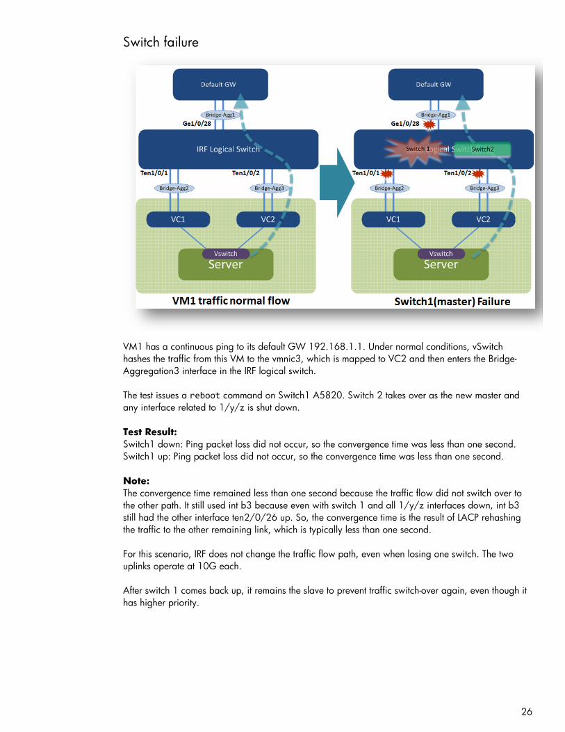
Switch failure
VM1 has a continuous ping to its default GW 192.168.1.1. Under normal conditions, vSwitch
hashes the traffic from this VM to the vmnic3, which is mapped to VC2 and then enters the Bridge-
Aggregation3 interface in the IRF logical switch.
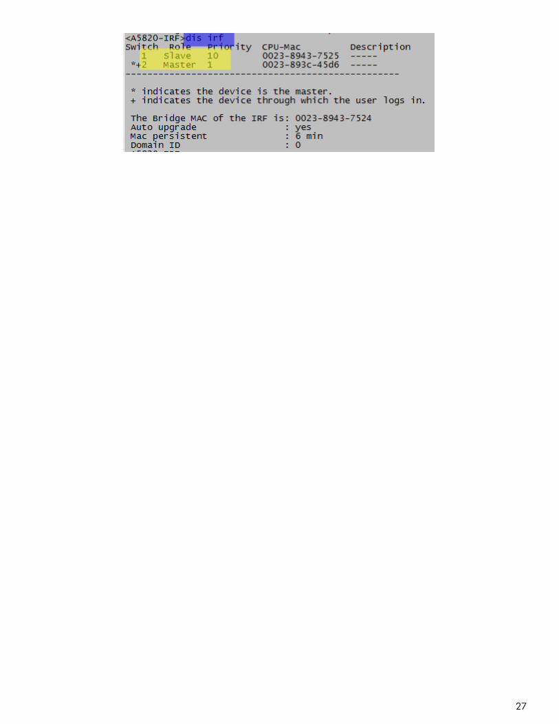
The test issues a reboot command on Switch1 A5820. Switch 2 takes over as the new master and
any interface related to 1/y/z is shut down.
Test Result:
Switch1 down: Ping packet loss did not occur, so the convergence time was less than one second.
Switch1 up: Ping packet loss did not occur, so the convergence time was less than one second.
Note:
The convergence time remained less than one second because the traffic flow did not switch over to
the other path. It still used int b3 because even with switch 1 and all 1/y/z interfaces down, int b3
still had the other interface ten2/0/26 up. So, the convergence time is the result of LACP rehashing
the traffic to the other remaining link, which is typically less than one second.
For this scenario, IRF does not change the traffic flow path, even when losing one switch. The two
uplinks operate at 10G each.
After switch 1 comes back up, it remains the slave to prevent traffic switch-over again, even though it
has higher priority.
27

28
IRF link failure
VM1 has a continuous ping to its default GW 192.168.1.1. Under normal conditions, the vSwitch
hashes the traffic from this VM to the vmnic3, which is mapped to the VC2 and then enters the Bridge-
Aggregation3 interface in the IRF logical switch.
The test issued a shut down command under switch1 A5820 IRF1/2 to simulate IRF link failure.
Test Result:
Shut irf-port 1/2: Ping packet loss did not occur, so the convergence time was less than one
second.
No shut irf-port 1/2: About one second packet loss after switch 2 rebooted and came back up to
join the IRF domain
Note:
Upon losing the IRF link, MAD initiates and elects one master for the domain, and the other switch
(switch 2 with lower IRF priority) shuts down all its local interfaces to prevent a dual active (split brain)
scenario. When the IRF link is restored, switch 2 reboots itself and rejoins the IRF domain.
Packet loss when Switch2 (A5800) came back and joined IRF domain:

29
Switch2 (A5800) view after IRF link failure with BFD MAD protection
Switch2 (A5800) view after all local interfaces were shut down to prevent a dual active scenario

30
Switch1 (A5820) console log after IRF-link fail
31
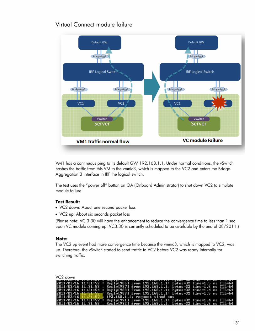
Virtual Connect module failure
VM1 has a continuous ping to its default GW 192.168.1.1. Under normal conditions, the vSwitch
hashes the traffic from this VM to the vmnic3, which is mapped to the VC2 and enters the Bridge-
Aggregation 3 interface in IRF the logical switch.
The test uses the “power off” button on OA (Onboard Administrator) to shut down VC2 to simulate
module failure.
Test Result:
VC2 down: About one second packet loss
VC2 up: About six seconds packet loss
(Please note: VC 3.30 will have the enhancement to reduce the convergence time to less than 1 sec
upon VC module coming up. VC3.30 is currently scheduled to be available by the end of 08/2011.)
Note:
The VC2 up event had more convergence time because the vmnic3, which is mapped to VC2, was
up. Therefore, the vSwitch started to send traffic to VC2 before VC2 was ready internally for
switching traffic.
VC2 down
32
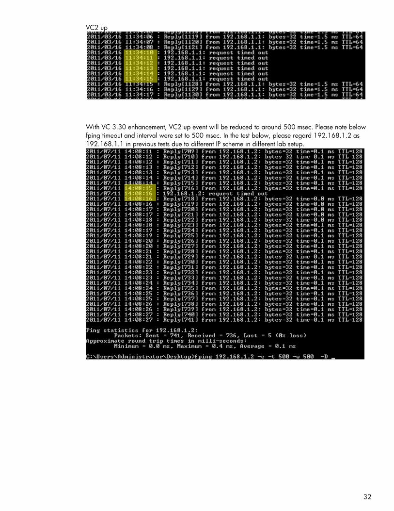
VC2 up
With VC 3.30 enhancement, VC2 up event will be reduced to around 500 msec. Please note below
fping timeout and interval were set to 500 msec. In the test below, please regard 192.168.1.2 as
192.168.1.1 in previous tests due to different IP scheme in different lab setup.

33
Insight Control for Vmware vCenter monitoring
Insight Control for vCenter utilizes a visual networking view from vSwitch to Virtual Connect to
physical access switch. The following images provide examples of its appearance and functionality.
VM1 uses vSwitch1, which has two uplinks (vmnic2 and vmnic3). The uplinks carry tagged packets
for VLAN (Virtual Local Area Network) 2 and VLAN 3. VLAN 3 is not in used in the testing but is
provided to show the concept of tagged trunking between Virtual Connect and vSwitch. The graphic
also displays the physical uplink ports used to connect to the access switch. The host name and MAC
address of that switch are also provided, and are obtained through the use of LLDP between Virtual
Connect and the network switch.

34
Host H/W inventory details

35
Host and Enclosure firmware version report

36
IMC network management
HP IMC is HP networking management software that supports network device configuration,
accounting, performance, security management, and monitoring. It can manage HP Network devices,
as well as routers and switches from other vendors.
The following images corresponding to this setup provide an overview of the appearance and
functionality of IMC. It does not represent the full functionality of IMC.
For more information on IMC, see the HP website:
http://h17007.www1.hp.com/us/en/products/network-management/index.aspx
To download full-featured evaluation software, see the HP website:
https://h10145.www1.hp.com/downloads/SoftwareReleases.aspx?ProductNumber=JF377A&lang=
en&cc=us&prodSeriesId=4176535
Overview page (can customize layout)

37
Network topology
5820 IRF logical switch

38
Virtual Connect interface list view
Interface traffic rate realtime monitoring

39
Appendix 1: A5820 logical switch IRF configuration
[A5820-IRF]dis current-configuration # version 5.20, Release 1206 # sysname A5820-IRF # irf mac-address persistent timer irf auto-update enable undo irf link-delay irf member 1 priority 10 # domain default enable system # telnet server enable # vlan 1 # vlan 2 # vlan 100 # radius scheme system server-type extended primary authentication 127.0.0.1 1645 primary accounting 127.0.0.1 1646 user-name-format without-domain # domain system access-limit disable state active idle-cut disable self-service-url disable # user-group system # stp mode rstp stp enable # interface Bridge-Aggregation1 port link-type trunk port trunk permit vlan 1 to 2 link-aggregation mode dynamic # interface Bridge-Aggregation2 port link-type trunk port trunk permit vlan 1 to 2 link-aggregation mode dynamic stp edged-port enable # interface Bridge-Aggregation3 port link-type trunk port trunk permit vlan 1 to 2 link-aggregation mode dynamic stp edged-port enable # interface NULL0 # interface Vlan-interface100

40
mad bfd enable mad ip address 100.100.100.1 255.255.255.0 member 1 mad ip address 100.100.100.2 255.255.255.0 member 2 # interface GigabitEthernet1/0/25 port link-mode bridge port access vlan 100 stp disable # interface GigabitEthernet1/0/26 port link-mode bridge # interface GigabitEthernet1/0/27 port link-mode bridge # interface GigabitEthernet1/0/28 port link-mode bridge port link-type trunk port trunk permit vlan 1 to 2 port link-aggregation group 1 # interface GigabitEthernet2/0/1 port link-mode bridge # interface GigabitEthernet2/0/2 port link-mode bridge # interface GigabitEthernet2/0/3 port link-mode bridge port access vlan 100 stp disable # interface GigabitEthernet2/0/4 port link-mode bridge # interface GigabitEthernet2/0/5 port link-mode bridge # interface GigabitEthernet2/0/6 port link-mode bridge # interface GigabitEthernet2/0/7 port link-mode bridge # interface GigabitEthernet2/0/8 port link-mode bridge # interface GigabitEthernet2/0/9 port link-mode bridge # interface GigabitEthernet2/0/10 port link-mode bridge # interface GigabitEthernet2/0/11 port link-mode bridge # interface GigabitEthernet2/0/12 port link-mode bridge # interface GigabitEthernet2/0/13 port link-mode bridge

41
# interface GigabitEthernet2/0/14 port link-mode bridge # interface GigabitEthernet2/0/15 port link-mode bridge # interface GigabitEthernet2/0/16 port link-mode bridge # interface GigabitEthernet2/0/17 port link-mode bridge # interface GigabitEthernet2/0/18 port link-mode bridge # interface GigabitEthernet2/0/19 port link-mode bridge # interface GigabitEthernet2/0/20 port link-mode bridge # interface GigabitEthernet2/0/21 port link-mode bridge # interface GigabitEthernet2/0/22 port link-mode bridge # interface GigabitEthernet2/0/23 port link-mode bridge # interface GigabitEthernet2/0/24 port link-mode bridge port link-type trunk port trunk permit vlan 1 to 2 port link-aggregation group 1 # interface M-GigabitEthernet0/0/0 ip address 10.1.8.2 255.255.0.0 # interface Ten-GigabitEthernet1/0/1 port link-mode bridge port link-type trunk port trunk permit vlan 1 to 2 port link-aggregation group 2 # interface Ten-GigabitEthernet1/0/2 port link-mode bridge port link-type trunk port trunk permit vlan 1 to 2 port link-aggregation group 3 # interface Ten-GigabitEthernet1/0/3 port link-mode bridge # interface Ten-GigabitEthernet1/0/4 port link-mode bridge # interface Ten-GigabitEthernet1/0/5 port link-mode bridge #

42
interface Ten-GigabitEthernet1/0/6 port link-mode bridge # interface Ten-GigabitEthernet1/0/7 port link-mode bridge # interface Ten-GigabitEthernet1/0/8 port link-mode bridge # interface Ten-GigabitEthernet1/0/9 port link-mode bridge # interface Ten-GigabitEthernet1/0/10 port link-mode bridge # interface Ten-GigabitEthernet1/0/11 port link-mode bridge # interface Ten-GigabitEthernet1/0/12 port link-mode bridge # interface Ten-GigabitEthernet1/0/13 port link-mode bridge # interface Ten-GigabitEthernet1/0/14 port link-mode bridge # interface Ten-GigabitEthernet1/0/15 port link-mode bridge # interface Ten-GigabitEthernet1/0/16 port link-mode bridge # interface Ten-GigabitEthernet1/0/17 port link-mode bridge # interface Ten-GigabitEthernet1/0/18 port link-mode bridge # interface Ten-GigabitEthernet1/0/19 port link-mode bridge # interface Ten-GigabitEthernet1/0/20 port link-mode bridge # interface Ten-GigabitEthernet1/0/21 port link-mode bridge # interface Ten-GigabitEthernet1/0/22 port link-mode bridge # interface Ten-GigabitEthernet2/0/25 port link-mode bridge port link-type trunk port trunk permit vlan 1 to 2 port link-aggregation group 2 # interface Ten-GigabitEthernet2/0/26 port link-mode bridge port link-type trunk port trunk permit vlan 1 to 2

43
port link-aggregation group 3 # interface Ten-GigabitEthernet1/0/23 # interface Ten-GigabitEthernet1/0/24 # interface Ten-GigabitEthernet2/0/27 # interface Ten-GigabitEthernet2/0/28 # ip route-static 0.0.0.0 0.0.0.0 10.1.0.1 # snmp-agent snmp-agent local-engineid 800063A203002389437528 snmp-agent community read public snmp-agent sys-info contact ASC-Admin snmp-agent sys-info location ASC snmp-agent sys-info version all snmp-agent target-host trap address udp-domain 10.1.220.178 udp-port 161 params securityname public snmp-agent trap enable default-route # load xml-configuration # user-interface aux 0 1 user-interface vty 0 15 authentication-mode none user privilege level 3 # irf-port 1/2 port group interface Ten-GigabitEthernet1/0/23 mode enhanced port group interface Ten-GigabitEthernet1/0/24 mode enhanced # irf-port 2/1 port group interface Ten-GigabitEthernet2/0/27 mode enhanced port group interface Ten-GigabitEthernet2/0/28 mode enhanced # return [A5820-IRF]

44
Appendix 2: Design 3 running status
Using design option three, if one port channel interface is configured on an A5820 switch and one
SUS is configured on a Virtual Connect to bundle four links on both sides, the A5820 switch does not
select two out of four links as active LACP links.
VC1 status is OK.
VC2 status is not OK. The “LAG ID” column is empty, which means no LACP bundle is established.
Both links are put into standby as individual links for this SUS.

45
Acronyms
ARP – Address Resolution Protocol
BFD – Bidirectional Forwarding Detection
BPDU - Bridge Protocol Data Unit
GW – Gateway
IC – Insight Control
IMC – Intelligent Management Center
IRF – Intelligent Resilient Framework
LACP – Link Aggression Control Protocol
LACPDU – Link Aggression Control Protocol Data Unit
LLDP – Link-Layer Discovery Protocol
MAC – Media Access Control
MAD – Multi-Active Detection
OA – Onboard Administrator
SSH – Secure Shell
STP – Spanning Tree Protocol
SUS – Shared Uplink Set
VC – Virtual Connect
VLAN – Virtual Local Area Network
VM – Virtual Machine
vPC – Virtual Port Channel
VSS – Virtual Switching System
© Copyright 2011 Hewlett-Packard Development Company, L.P. The information contained herein is subject to
change without notice. The only warranties for HP products and services are set forth in the express warranty
statements accompanying such products and services. Nothing herein should be construed as constituting an
additional warranty. HP shall not be liable for technical or editorial errors or omissions contained herein.
c02843088, Created May 2011, Updated July 2011