Embed Size (px)
Citation preview

Virtual Backbone Construction in MANETs usingAdjustable Transmission Ranges∗
Jie WuDepartment of Computer Science and Engineering
Florida Atlantic UniversityBoca Raton, FL 33431Email: [email protected]
Fei DaiDepartment of Electrical and Computer Engineering
North Dakota State UniversityFargo, ND 58105
Email: [email protected]
Abstract
Recently, the use of a virtual backbone in various applications in mobile ad hoc networks
(MANETs) has become popular. These applications include topology management, point and
area coverage, and routing protocol design. In a MANET, one challenging issue is to construct
a virtual backbone in a distributed and localized way while balancing several conflicting objec-
tives: small approximation ratio, fast convergence, and low computation cost. Many existing
distributed and localized algorithms select a virtual backbone without resorting to global or
geographical information. However, these algorithms incur a high computation cost in a dense
network. In this paper, we propose a distributed solution based on reducing the density of
the network using two mechanisms: clustering and adjustable transmission range. By using
adjustable transmission range, we also achieve another objective, energy-efficient design, as a
by-product. As an application, we show an efficient broadcast scheme where nodes (and only
∗This work was supported in part by NSF grants CCR 0329741, CNS 0434533, CNS 0422762, and EIA 0130806.A preliminary version appeared in the Proceedings of the 24th International Conference on Distributed ComputingSystems (ICDCS 2004).
1

nodes) in a virtual backbone are used to forward the broadcast message. The virtual backbone
is constructed using Wu and Li’s marking process [37] and the proposed density reduction
process. The application of the density reduction process to other localized algorithms is also
discussed. The efficiency of our approach is confirmed through both analytical and simulation
study.
keywords: Adjustable transmission range, broadcasting, clustering, connected dominating set
(CDS), energy efficiency, mobile ad hoc networks (MANETs).
1 Introduction
Although a mobile ad hoc network (or simply MANET) has no physical backbone infrastructure,
a virtual backbonecan be formed by nodes in aconnected dominating set(CDS) of the unit-
disk graph of a given MANET. Recently, the use of a virtual backbone in various applications in
MANETs has become popular. These applications include topology management in MANETs,
point and area coverage in sensor networks, and routing protocol design. A dominating set (DS) is
a subset of nodes in the network where every node is either in the subset or a neighbor of a node in
the subset. In a unit-disk graph, node connections are determined by their geographical distances.
It has been proved that finding the minimum CDS in a unit-disk graph is NP-complete.
A common source of overhead in a MANET comes from blind flooding/broadcasting, where
a broadcast message is forwarded by every node in the network exactly once. Broadcasting is
used by the route discovery process in several reactive routing protocols. Due to the broadcast
nature of wireless communication (i.e., when a source sends a message, all of its neighbors will
hear it), blind flooding/broadcasting may generate excessive redundant transmission. Redundant
transmission may cause a serious problem, referred to as the broadcast storm problem [31], in
which redundant messages cause communication contention and collision. In Figure 1(a), when
each node forwards the message once, nodew will receive the same message six times. To reduce
redundant transmission, nodes (and only nodes) in the virtual backbone forward the broadcast
message once when they receive the message for the first time.
In a MANET, one challenging issue is to construct a virtual backbone in a a distributed and
localized way while balancing several conflicting objectives: small approximation ratio, fast con-
2
vergence, and low computation cost. Many existing distributed and localized algorithms can select
a virtual backbone without resorting to global or geographical information. For example, in Wu and
Li’s marking process [37], each node is marked (i.e., in a CDS) if it has two unconnected neigh-
bors. The marking process is effective in reducing the size of the CDS. In addition, it supports
localized maintenance in a mobile environment. However, the process incurs a high communica-
tion and computation cost in a dense network, since each node needs to exchange neighbor sets
among 1-hop neighbors and to check all pairs of its neighbors.
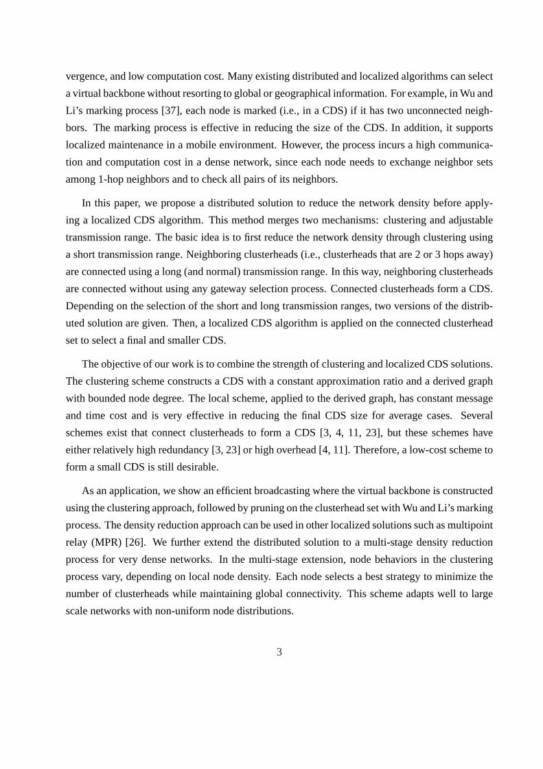
In this paper, we propose a distributed solution to reduce the network density before apply-
ing a localized CDS algorithm. This method merges two mechanisms: clustering and adjustable
transmission range. The basic idea is to first reduce the network density through clustering using
a short transmission range. Neighboring clusterheads (i.e., clusterheads that are 2 or 3 hops away)
are connected using a long (and normal) transmission range. In this way, neighboring clusterheads
are connected without using any gateway selection process. Connected clusterheads form a CDS.
Depending on the selection of the short and long transmission ranges, two versions of the distrib-
uted solution are given. Then, a localized CDS algorithm is applied on the connected clusterhead
set to select a final and smaller CDS.
The objective of our work is to combine the strength of clustering and localized CDS solutions.
The clustering scheme constructs a CDS with a constant approximation ratio and a derived graph
with bounded node degree. The local scheme, applied to the derived graph, has constant message
and time cost and is very effective in reducing the final CDS size for average cases. Several
schemes exist that connect clusterheads to form a CDS [3, 4, 11, 23], but these schemes have
either relatively high redundancy [3, 23] or high overhead [4, 11]. Therefore, a low-cost scheme to
form a small CDS is still desirable.
As an application, we show an efficient broadcasting where the virtual backbone is constructed
using the clustering approach, followed by pruning on the clusterhead set with Wu and Li’s marking
process. The density reduction approach can be used in other localized solutions such as multipoint
relay (MPR) [26]. We further extend the distributed solution to a multi-stage density reduction
process for very dense networks. In the multi-stage extension, node behaviors in the clustering
process vary, depending on local node density. Each node selects a best strategy to minimize the
number of clusterheads while maintaining global connectivity. This scheme adapts well to large
scale networks with non-uniform node distributions.
3

w
u v
x y(a)
ts w
v
x y(b)
u
ts w
u v
x y
s t
(c)
Figure 1: (a) Broadcast storm problem. (b) Marked nodes: black (marked by the marking process)
and double circled (survivors after applying Rulek). (c) Clustering approach: black nodes (clus-
terheads) and white nodes (non-clusterheads).
By using adjustable transmission range, we also achieve several other goals as by-products:
reducing the computation complexity of the broadcast algorithm, maximizing the traffic capacity
of the network, reducing the power consumption of the broadcast process, prolonging the life span
of each individual node, and reducing the contention at the MAC layer.
2 Related work
Wu and Lou [38] gave a comprehensive classification of CDS construction algorithms in MANETs:
global, quasi-global, quasi-local, andlocal. Global solutions, such as Guha and Khuller’s greedy
algorithm [14], are based on global state information and are expensive in MANETs. Quasi-global
solutions, such as Alzoubi et al’s tree-based approach [4], require network-wide coordination,
which causes slow convergence in large scale networks. Many cluster-based approaches [3, 23, 38]
are quasi-local. The status (clusterhead/non-clusterhead) of each node depends on the status of its
neighbors, which in turn depends on the status of neighbors’ neighbors and so on. The propagation
of status information is relatively short (O(log n)) on average, but, in the worst case, can span
the entire network. Dubhashi et al [11] proposed another quasi-local approach, with bounded
(O(log n)) steps of status propagation. In local approaches (i.e., localized algorithms), the status
of each node depends on itsk-hop information only with a smallk, and there is no propagation of
status information. Local CDS formation algorithms include Wu and Li’s marking process (MP)
[37], several MP variations [8, 10], Qayyum, Viennot, and Laouiti’s multipoint relay (MPR) [26],
and MPR extensions [1, 22, 24], which will be discussed in Section 3.1.
4
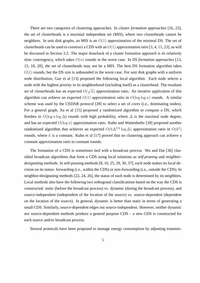
There are two categories of clustering approaches. Incluster formation approaches[16, 23],
the set of clusterheads is a maximal independent set (MIS), where two clusterheads cannot be
neighbors. In unit disk graphs, an MIS is anO(1) approximation of the minimal DS. The set of
clusterheads can be used to construct a CDS with anO(1) approximation ratio [3, 4, 11, 23], as will
be discussed in Section 3.2. The major drawback of a cluster formation approach is its relatively
slow convergency, which takesO(n) rounds in the worst case. InDS formation approaches[13,
15, 18, 28], the set of clusterheads may not be a MIS. The best DS formation algorithm takes
O(1) rounds, but the DS size is unbounded in the worst case. For unit disk graphs with a uniform
node distribution, Gao et al [13] proposed the following local algorithm. Each node selects a
node with the highest priority in its neighborhood (including itself) as a clusterhead. The resultant
set of clusterheads has an expectedO(√
n) approximation ratio. An iterative application of this
algorithm can achieve an expectedO(1) approximation ratio inO(log log n) rounds. A similar
scheme was used by the CEDAR protocol [28] to select a set ofcores(i.e., dominating nodes).
For a general graph, Jia et al [15] proposed a randomized algorithm to compute a DS, which
finishes inO(log n log ∆) rounds with high probability, where∆ is the maximal node degree,
and has an expectedO(log n) approximation ratio. Kuhn and Wattenhofer [18] proposed another
randomized algorithm that achieves an expectedO(k∆2/k log ∆) approximation ratio inO(k2)
rounds, wherek is a constant. Kuhn et al [17] proved that no clustering approach can achieve a
constant approximation ratio in constant rounds.
The formation of a CDS is sometimes tied with a broadcast process. Wu and Dai [36] clas-
sified broadcast algorithms that form a CDS using local solutions asself-pruningandneighbor-
designatingmethods. In self-pruning methods [8, 10, 25, 29, 30, 37], each node makes its local de-
cision on its status: forwarding (i.e., within the CDS) or non-forwarding (i.e., outside the CDS). In
neighbor-designating methods [22, 24, 26], the status of each node is determined by its neighbors.
Local methods also have the following two orthogonal classifications based on the way the CDS is
constructed: static (before the broadcast process) vs. dynamic (during the broadcast process), and
source-independent (independent of the location of the source) vs. source-dependent (dependent
on the location of the source). In general, dynamic is better than static in terms of generating a
small CDS. Similarly, source-dependent edges out source-independent. However, neither dynamic
nor source-dependent methods produce a general purpose CDS – a new CDS is constructed for
each source and/or broadcast process.
Several protocols have been proposed to manage energy consumption by adjusting transmis-
5

sion ranges. In the source-dependent approach (called minimum energy broadcast), the source is
given, but the problem is still NP-complete [9]. Clementi et al [9] proved that the minimum energy
broadcast problem is approximable with a constant factor in wireless networks. Wieselthier et al
[35] proposed several global algorithms. Two of those algorithms, MST (minimal spanning tree)
and BIP (broadcasting incremental power), were shown by Wan et al [32] to have a small approxi-
mation ratio of 12. Recently, a localized scheme [7] was proposed using a graph density reduction
method based on RNG (relative neighborhood graph). This approach uses location information in
addition to neighborhood information, which increases the cost.
In the source-independent approach (called topology control), all nodes can be a source and
are able to reach all other nodes by assigning appropriate ranges. The problem of minimizing
the total transmission power consumption (based on an assigned model) is NP-complete. Several
localized solutions exist based on local spanning subgraphs, such as SPT [27], RNG [7], and MST
[20]. Recently, new algorithms have been proposed to achieve multiple desirable properties such
as low message cost, constant stretch ratio [34], low weight [21], and minimal interference [6].
Another concern is the overhead. Most localized topology control schemes require 1-hop location
information, which becomes expensive to collect in very dense networks. An expanding search
region mechanism [5, 19, 27] was devised to solve this problem. The cone-based scheme [19]
requires only the AoA (angle-of-arrival) information of a few neighbors in a small search region.
Probabilistic schemes, such as K-Neigh [5], preserve connectivity with high probability and collect
only topology information in the search region. Topology control schemes sparsify a network by
removing edges and reducing transmission ranges. Some of them [20, 21, 34] guarantee a bounded
node degree. On the other hand, the purpose of CDS construction is to reduce the number of active
nodes. Although both approaches conserve energy and bandwidth consumption, they have different
sets of applications and cannot replace each other.
In this paper, we use the static and source-independent approach for CDS construction since it
is more generic. The resultant CDS is suitable for all situations. We also assume that no location
information is provided.
6
3 Preliminaries
3.1 CDS formation algorithms
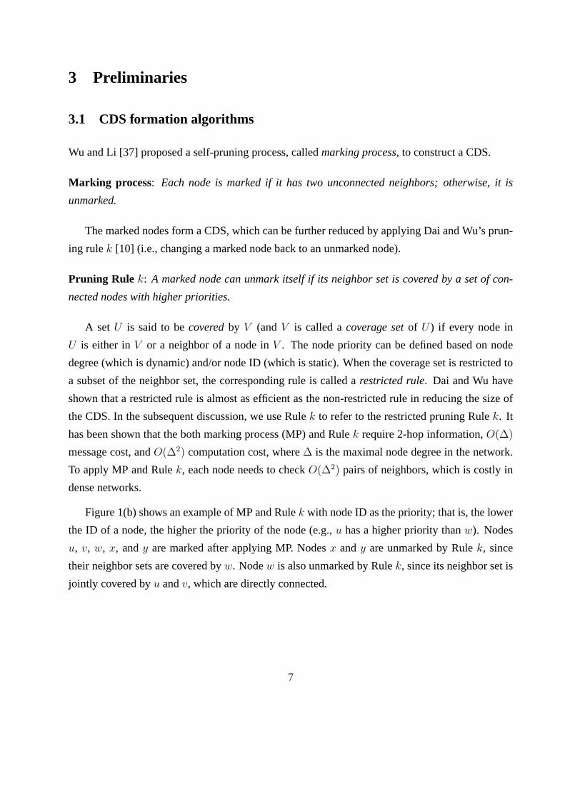
Wu and Li [37] proposed a self-pruning process, calledmarking process, to construct a CDS.
Marking process: Each node is marked if it has two unconnected neighbors; otherwise, it is
unmarked.
The marked nodes form a CDS, which can be further reduced by applying Dai and Wu’s prun-
ing rulek [10] (i.e., changing a marked node back to an unmarked node).
Pruning Rule k: A marked node can unmark itself if its neighbor set is covered by a set of con-
nected nodes with higher priorities.
A set U is said to becoveredby V (andV is called acoverage setof U ) if every node in
U is either inV or a neighbor of a node inV . The node priority can be defined based on node
degree (which is dynamic) and/or node ID (which is static). When the coverage set is restricted to
a subset of the neighbor set, the corresponding rule is called arestricted rule. Dai and Wu have
shown that a restricted rule is almost as efficient as the non-restricted rule in reducing the size of
the CDS. In the subsequent discussion, we use Rulek to refer to the restricted pruning Rulek. It
has been shown that the both marking process (MP) and Rulek require 2-hop information,O(∆)
message cost, andO(∆2) computation cost, where∆ is the maximal node degree in the network.
To apply MP and Rulek, each node needs to checkO(∆2) pairs of neighbors, which is costly in
dense networks.
Figure 1(b) shows an example of MP and Rulek with node ID as the priority; that is, the lower
the ID of a node, the higher the priority of the node (e.g.,u has a higher priority thanw). Nodes
u, v, w, x, andy are marked after applying MP. Nodesx andy are unmarked by Rulek, since
their neighbor sets are covered byw. Nodew is also unmarked by Rulek, since its neighbor set is
jointly covered byu andv, which are directly connected.
7

3.2 Clustering approach
The clustering approach is commonly used to offer scalability and is efficient in a dense network.
Basically, the network is partitioned into a set of clusters, with one clusterhead in each cluster.
Clusterheads form a DS and no two clusterheads are neighbors. Each clusterhead directly connects
to all its members (also called non-clusterheads). The classical clustering algorithm, also called
the cluster-based scheme, works as follows.
Cluster formation : (1) A nodev is aclusterheadif it has the highest priority in its 1-hop neighbor-
hood includingv. (2) A clusterhead and its neighbors form a cluster and these nodes arecovered.
(3) Repeat (1) and (2) on all uncovered nodes (if any).
Figure 1(c) shows an example of the clustering process. Boths andt are clusterheads (black
nodes) since they are local minima (in terms of node ID).u andx belong to clusters while v and
y belong to clustert. Nodew can belong to eithers or t. If the node ID ofw is changed tom in
Figure 1(c), nodem is the only clusterhead. When a node has multiple adjacent clusterheads, it
belongs to one of them. The cluster formation may need several rounds to complete, depending on
the network topology and the priority distribution.
Once the cluster formation process is complete, some non-clusterheads are designated asgate-
waysto connect clusterheads. In early schemes [23], every border node (i.e., non-clusterhead that
has a neighbor in another cluster) is a gateway, which results in a large CDS. In the tree scheme [4],
a clusterhead is first elected as the root. Then the root initiates a flooding to build a rooted tree. In
the mesh scheme [3], each clusterhead designates gateways to connect all neighboring clusterheads
(i.e., clusterheads within 3 hops). Both the tree and mesh schemes have constant approximation
ratios. The tree scheme achieves a better ratio at the expense of slower convergence.
In the core-based approach [13, 28], clusterheads (called core nodes) are permitted to be ad-
jacent, but the core formation can be done in a constant number of rounds without sequential
propagation. The original core-based approach is non-deterministic (i.e. time-sensitive depend-
ing on when each node participates in the formation process). Here we consider a simplified and
deterministic version.
Core formation: A nodev becomes a core node if (1) it has the highest priority among its 1-hop
neighbors includingv (v is selected by itself as a core node), or (2) it has the highest priority based
8

I
IIIII
u
v
w
x
y
z
(a)
u
v
w
x
y
z
(b)
Figure 2: The clustering approach with black nodes as clusterheads in (a) and cores in (b).
on a neighbor’s 1-hop neighborhood (v is selected by a neighbor as a core node).
Figure 2 shows the application of both cluster and core formations to the same network. Node
degree is used as the priority and node ID is used to break a tie in node degree. In this case, the
priority in decreasing order isu > v > w > x > y > z. Black nodes are clusterheads/core
nodes. In Figure 2(a), each Roman numeral indicates the round number (assume the formation is
synchronous) in which the corresponding node is selected as a clusterhead. Each dashed arrow
line in Figure 2 indicates theselectorof each core node. Like clusterheads, core nodes can be
connected via gateways to connect neighboring core nodes. To distinguish these two approaches,
the former is called a cluster formation, where clusterheads are not adjacent, and the latter is called
a core formation.
4 Backbone Formation in Dense Networks
This section proposes a density-reduction approach that can be integrated into any local approach
for CDS construction, using MP and Rulek as an example. In the proposed methods, the network
density is first reduced using clustering with a short transmission range. Then neighboring cluster-
heads are connected using a long (and normal) transmission range. In this way clusterheads form a
CDS without using gateways. This CDS is further reduced by applying MP and Rulek. Depending
on the selection of the short and long transmission ranges, two approaches can be used to construct
a backbone. The first approach adopts a 2-level hierarchy: In the lower level, the entire network
is covered by the set of clusterheads under the short transmission range. In the upper level, all
9

clusterheads are covered by the set ofmarked clusterheadsunder the long transmission range. The
second approach constructs a flat backbone, where the entire network is directly covered by the set
of marked clusterheads with the long transmission range. For each approach, we show an efficient
broadcast scheme as an application.
4.1 2-level clustering approach
We first used different transmission ranges at different stages of the protocol handshake, and then
applied the long (and normal) transmission range in broadcasting among clusterheads and the
short transmission range in broadcasting within each cluster with an unmarked clusterhead. This
approach is similar to the clustering approach that forms a CDS in a dense graph. However, unlike
the regular clustering approach where a selection process is needed to select gateway nodes to
connect clusterheads, we used a reduced transmission range for clustering. The virtual backbone
formation procedure is as follows:
Marking process on clusterheads
1. Each node uses a transmission range ofr/3 for cluster formation.
2. Each clusterhead uses a transmission range ofr for MP and Rulek.
In the above process, the backbone is constructed based on clusterheads using a transmission
range ofr/3. A transmission range ofr/3 ensures that all neighboring clusterheads (i.e., cluster-
heads within 3 hops) are directly connected under a transmission range ofr.
More formally, we useG = (V, P (V ), r) to represent a unit disk graph with node setV ,
a mappingP : V → R2, where R is the real number set, andr ∈ R+ represents a uniform
transmission range from the positive real number setR+. P maps each node inV to an (x, y)
point in 2-D space. Two nodes are connected if their Euclidean distance is no more thanr. G can
be simplified toG(r) to represent a unit disk graph with a uniform transmission range ofr. It is
assumed thatG(r/k) is still a connected graph for a smallk such ask = 3 or 4. This assumption
is reasonable under the unit disk graph model when the network is relatively dense and uniformly
distributed. These requirements will be relaxed in the next section, where the backbone formation
algorithm is extended to non-perfect unit disk graphs with a non-uniform node distribution.
10

r/3
(a)
vu
w
(b)
vu
w
r
(c)
vu
w
r
r
r/3
Figure 3: (a) Cluster formation with a transmission range ofr/3. (b) Marking process with a trans-
mission range ofr. (c) Clusterheads forward the broadcast message with different transmission
ranges. Marked clusterheads are black, unmarked clusterheads are gray, and non-clusterheads are
white.
Lemma 1 Under the unit disk graph model, a DS ofG(r1) is a CDS ofG(r2), if G(r1) is connected
andr2 ≥ 3r1.
Proof: Let V′
be a DS ofG(r1). An alternative definition of a CDS is that any node pair in the
network is connected via nodes in the CDS (i.e., the backbone nodes). For any two nodesu and
v, we can construct a path(u,w1, w2, . . . , wl, v) in G(r2), such thatwi ∈ V′for 1 ≤ i ≤ l. Since
G(r1) is connected, a path(u = x1, x2, . . . , xl = v) exists inG(r1). For eachxi (1 ≤ i ≤ l), there
is a correspondingwi ∈ V′that is eitherxi itself or a neighbor ofxi. The distance betweenxi and
wi is d(xi, wi) ≤ r1. The distance betweenwi andwi+1 is d(wi, wi+1) ≤ d(wi, xi) + d(xi, xi+1) +
d(xi+1, wi+1) ≤ 3r1 ≤ r2. Therefore,(u, w1, w2, . . . , wl, v) is a valid path inG(r2). 2
The ratior2 = 3r1 (or r1 = r2/3) is tight. A CDS cannot be guaranteed ifr1 > r2/3. On the
other hand, using a shorterr1 will produce a larger clusterhead set, which is undesirable. Because
the set of clusterheads is a DS, the following theorem can be proved based on Lemma 1.
Theorem 1The clusterhead setV′, derived fromG(r/3) via clustering, is a CDS ofG(r).
Let G′(r) be the subgraph ofG(r) derived fromV
′. Since MP and Rulek preserve a CDS, we
have:
Corollary 1 : V′′
derived from the MP and Rulek is a CDS ofG′(r).
11

Figure 3(b) illustrates the stage of applying MP and Rulek on clusterheads using a transmis-
sion range ofr. As a result of the above process, the marked clusterheads form a CDS among
clusterheads. The broadcast process is as follows:
Broadcast process
1. If the source is a non-clusterhead, it transmits the message with a transmission range ofr/3
to thesource clusterhead.
2. The source clusterhead transmits the message with a transmission range ofr.
3. At each intermediate node, if the node is a marked clusterhead, it forwards the message with
a transmission range ofr and if it is an unmarked clusterhead, it forwards the message with
a transmission range ofr/3; otherwise, it does nothing.
Theorem 2The broadcast process ensures full coverage.
Proof: Based on the broadcast process, if the source is not a clusterhead, it will forward the
message to its clusterhead. Once the message is received by one clusterhead, it will be forwarded
by marked clusterheads inV′′
to all clusterheads inV′(Corollary 1). Each clusterhead will forward
once, using a transmission range ofr if it is marked, or a transmission range ofr/3 if it is unmarked.
In either case, each clusterhead will cover all members (non-clusterheads) that are withinr/3. 2
When the notion of clusterhead coverage is extended to cover clusterheads and all their mem-
bers, each unmarked clusterhead is still required to forward the message with a transmission range
of r/3 to ensure coverage within its cluster, because when MP and Rulek are used, the coverage
is only extended to all clusterheads, not to all their members which are withinr/3. Figure 3(c)
shows the broadcast process in the 2-level clustering approach.
4.2 1-level flat approach
In the 2-level clustering approach, the broadcast process involves both inter-cluster and intra-
cluster broadcast using different transmission ranges. In the 1-level flat approach, the notion of
clustering is removed by using a uniform transmission range. Still, different transmission ranges
12
are used at different stages of the protocol handshake. The modified cluster formation procedure
is as follows:
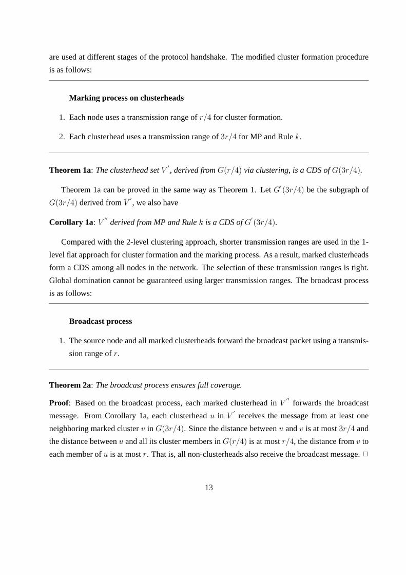
Marking process on clusterheads
1. Each node uses a transmission range ofr/4 for cluster formation.
2. Each clusterhead uses a transmission range of3r/4 for MP and Rulek.
Theorem 1a: The clusterhead setV′, derived fromG(r/4) via clustering, is a CDS ofG(3r/4).
Theorem 1a can be proved in the same way as Theorem 1. LetG′(3r/4) be the subgraph of
G(3r/4) derived fromV′, we also have
Corollary 1a: V′′
derived from MP and Rulek is a CDS ofG′(3r/4).
Compared with the 2-level clustering approach, shorter transmission ranges are used in the 1-
level flat approach for cluster formation and the marking process. As a result, marked clusterheads
form a CDS among all nodes in the network. The selection of these transmission ranges is tight.
Global domination cannot be guaranteed using larger transmission ranges. The broadcast process
is as follows:
Broadcast process
1. The source node and all marked clusterheads forward the broadcast packet using a transmis-
sion range ofr.
Theorem 2a: The broadcast process ensures full coverage.
Proof: Based on the broadcast process, each marked clusterhead inV′′
forwards the broadcast
message. From Corollary 1a, each clusterheadu in V′
receives the message from at least one
neighboring marked clusterv in G(3r/4). Since the distance betweenu andv is at most3r/4 and
the distance betweenu and all its cluster members inG(r/4) is at mostr/4, the distance fromv to
each member ofu is at mostr. That is, all non-clusterheads also receive the broadcast message.2
13
r/4
(a)
vu
w
(b)
vu
w
3r/4
(c)
vu
w
r
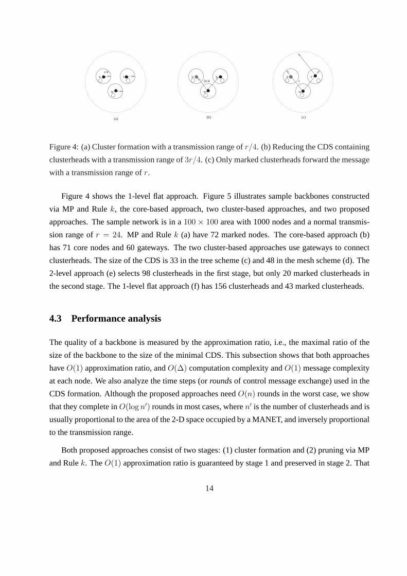
Figure 4: (a) Cluster formation with a transmission range ofr/4. (b) Reducing the CDS containing
clusterheads with a transmission range of3r/4. (c) Only marked clusterheads forward the message
with a transmission range ofr.
Figure 4 shows the 1-level flat approach. Figure 5 illustrates sample backbones constructed
via MP and Rulek, the core-based approach, two cluster-based approaches, and two proposed
approaches. The sample network is in a100 × 100 area with 1000 nodes and a normal transmis-
sion range ofr = 24. MP and Rulek (a) have 72 marked nodes. The core-based approach (b)
has 71 core nodes and 60 gateways. The two cluster-based approaches use gateways to connect
clusterheads. The size of the CDS is 33 in the tree scheme (c) and 48 in the mesh scheme (d). The
2-level approach (e) selects 98 clusterheads in the first stage, but only 20 marked clusterheads in
the second stage. The 1-level flat approach (f) has 156 clusterheads and 43 marked clusterheads.
4.3 Performance analysis
The quality of a backbone is measured by the approximation ratio, i.e., the maximal ratio of the
size of the backbone to the size of the minimal CDS. This subsection shows that both approaches
haveO(1) approximation ratio, andO(∆) computation complexity andO(1) message complexity
at each node. We also analyze the time steps (orroundsof control message exchange) used in the
CDS formation. Although the proposed approaches needO(n) rounds in the worst case, we show
that they complete inO(log n′) rounds in most cases, wheren′ is the number of clusterheads and is
usually proportional to the area of the 2-D space occupied by a MANET, and inversely proportional
to the transmission range.
Both proposed approaches consist of two stages: (1) cluster formation and (2) pruning via MP
and Rulek. TheO(1) approximation ratio is guaranteed by stage 1 and preserved in stage 2. That
14

0 1 2 3 4 5 6 7 8 9 100
1
2
3
4
5
6
7
8
9
10
��
��
��
��
����
��
��
��
��
��
��
��
��
��
��
��
��
��
��
��
��
����
��
��
��
��
��
��
��
����
��
��
��
��
��
��
��
��
��
����
��
��
��
��
��
��
��
��
��
��
��
��
��
��
��
��
����
��
��
��
��
��
��
��
��
��
��
��
��
��
��
��
��
��
��
��
��
��
��
��
��
��
��
��
��
��
��
��
��
����
��
��
��
��
��
��
��
��
��
��
��
����
��
��
��
��
��
��
��
��
��
��
��
��
��
��
��
��
��
��
��
��
��
��
��
��
��
��
��
��
��
��
��
��
��
��
��
��
��
��
��
��
��
��
��
��
��
��
��
��
��
��
��
��
��
��
��
��
��
��
��
��
��
��
��
��
��
����
��
��
��
��
��
��
��
��
��
��
��
��
��
��
��
��
��
��
��
��
��
��
��
��
��
��
��
��
��
��
��
��
��
��
��
��
��
��
��
��
��
��
��
��
��
��
����
��
��
��
��
��
��
��
��
��
��
��
��
��
��
��
��
��
��
��
��
��
����
��
��
��
��
��
��
��
��
��
��
��
��
��
��
��
��
��
��
��
��
��
����
��
��
��
��
��
��
��
��
��
��
��
��
��
��
��
��
��
��
��
��
��
��
��
��
��
��
��
��
����
��
��
��
��
����
��
��
��
��
��
��
��
��
��
��
��
��
��
��
��
��
��
��
��
��
��
��
��
��
����
��
��
��
��
��
��
��
��
��
��
��
����
��
��
��
��
��
��
��
��
��
��
��
��
��
��
��
��
��
��
��
��
��
��
��
��
��
��
��
��
��
��
��
��
��
��
��
����
��
��
��
����
��
����
��
��
����
��
��
����
��
��
��
��
��
��
��
��
��
��
��
��
��
��
��
��
��
��
��
��
��
��
��
��
��
��
��
����
��
��
��
��
��
��
��
��
����
��
��
��
��
��
��
��
��
��
��
��
��
��
������
��
��
��
��
��
��
��
��
��
��
��
��
��
��
��
����
��
��
��
��
��
��
��
��
��
��
��
��
����
��
��
��
��
��
��
��
��
��
��
����
����
��
����
��
��
��
��
��
��
��
��
��
��
��
��
��
��
��
��
����
��
����
��
��
��
��
��
��
��
��
��
��
��
��
��
����
��
��
��
����
��
��
��
��
��
��
��
��
��
��
��
��
��
��
��
��
��
��
��
��
��
��
��
��
��
��
��
��
��
��
��
��
��
����
��
��
��
��
��
��
��
��
��
��
��
��
��
��
��
����
��
��
����
��
��
��
��
��
��
��
��
��
��
��
��
��
��
��
��
��
��
��
��
��
��
��
��
��
��
��
��
��
��
��
��
��
��
��
��
��
��
��
��
����
��
��
��
��
��
��
��
��
��
��
��
����
��
��
��
��
��
��
��
��
��
��
��
����
��
��
��
��
��
��
��
��
��
��
��
��
��
��
������
��
��
��
��
����
��
��
��
��
��
��
��
��
��
��
��
��
��
��
��
��
��
��
��
����
��
��
��
����
��
��
��
��
��
��
��
��
��
��
��
��
��
��
��
��
��
��
��
��
��
��
��
��
��
��
��
��
��
��
��
��
��
��
��
��
��
��
��
��
��
��
��
��
��
��
��
��
��
��
��
��
��
��
��
��
��
��
��
��
��
��
��
��
��
����
��
��
��
��
��
����
��
��
����
��
��
��
��
��
����
��
��
��
��
��
��
��
��
��
��
����
��
��
��
��
��
��
��
��
��
��
��
��
��
��
��
��
��
��
��
��
��
��
��
��
��
��
��
��
��
��
��
��
��
��
����
��
��
��
��
��
��
��
��
��
��
��
��
��
��
��
��
��
��
��
��
��
��
��
��
��
��
��
��
��
��
��
��
��
��
��
��
��
��
��
��
��
��
��
����
��
��
��
��
��
��
��
��
��
��
��
��
��
��
��
��
��
��
��
��
��
��
��
��
��
��
��
����
��
��
��
����
��
�
�
�
�
�
�
�
�
�
�
�
�
�
�
���
�
�
�
�
�
�
���
��
�
�
�
�
�
�
�
�
�
�
�
�
�
�
�
�
�
�
�
�
�
��
�
�
�
�
�
�
�
�
��
��
�
�
�
�
�
�
�
�
�
r
4
(a) MP and Rulek
0 1 2 3 4 5 6 7 8 9 100
1
2
3
4
5
6
7
8
9
10
��
��
��
��
��
��
��
��
��
��
��
��
��
��
��
��
��
��
��
��
��
����
��
��
��
��
��
��
��
��
��
��
��
����
��
��
��
��
��
��
��
��
��
��
��
��
��
��
��
��
��
��
��
��
��
��
��
����
��
��
��
��
��
��
��
��
��
��
��
��
��
��
��
��
��
��
��
��
��
��
��
��
����
��
��
��
��
��
��
��
����
��
��
��
��
��
��
��
��
��
��
��
��
��
��
��
��
��
��
��
��
��
��
��
��
��
��
��
��
��
��
��
��
��
����
��
��
��
��
��
��
����
��
��
��
��
��
��
��
��
��
��
��
��
��
��
��
��
��
��
��
��
��
��
������
��
��
��
��
��
��
��
��
��
��
��
��
��
��
��
��
��
��
��
��
��
��
��
��
��
��
��
��
��
��
��
����
��
��
��
��
��
��
��
����
��
��
��
��
��
��
��
��
��
��
����
��
��
��
��
��
��
��
����
��
��
��
��
��
��
��
��
��
��
��
��
��
����
��
��
��
��
��
��
��
��
��
��
��
��
��
��
��
��
��
��
��
��
��
��
��
��
��
��
��
��
��
��
��
��
��
��
��
��
��
��
��
��
��
��
��
��
��
��
��
��
��
��
��
����
��
����
��
��
����
��
��
��
��
��
��
��
��
��
��
��
��
��
��
��
��
��
��
��
��
��
��
��
��
��
��
��
��
��
��
��
��
��
����
��
��
��
��
����
��
��
��
��
��
��
��
��
��
����
��
��
��
��
��
��
��
��
��
��
��
��
��
��
��
��
����
��
��
����
��
��
��
��
��
��
��
��
��
��
��
��
��
��
��
��
��
��
��
��
��
��
��
��
��
��
��
��
��
��
��
��
��
��
��
��
��
����
��
��
��
��
��
��
��
��
��
��
��
��
��
��
��
��
��
��
��
��
��
��
��
��
��
��
��
��
��
��
��
����
��
��
��
��
��
��
��
��
��
��
��
��
��
��
��
��
��
��
��
��
��
��
��
��
��
��
��
��
����
��
��
��
��
��
��
��
��
��
����
��
��
��
��
��
��
��
��
����
��
��
��
����
��
��
��
��
��
��
����
��
��
��
��
��
��
��
��
��
��
��
��
��
��
��
��
��
��
��
����
��
��
��
��
��
��
��
��
��
��
��
��
��
��
��
��
��
��
��
��
��
��
��
��
��
��
��
��
��
��
��
��
��
��
��
��
��
����
��
��
����
����
��
��
��
��
��
��
��
��
��
��
��
��
��
��
��
��
��
��
��
��
��
��
��
��
��
��
��
��
��
����
��
��
��
��
��
��
��
��
��
��
��
��
��
��
��
����
��
��
��
��
��
��
��
��
��
��
��
��
��
��
��
��
��
��
��
��
��
��
��
��
��
��
��
����
��
��
��
��
��
��
��
��
��
��
��
��
��
��
��
��
��
��
��
��
��
��
��
��
��
��
��
��
��
��
��
��
��
��
��
��
��
��
��
��
��
����
��
��
��
��
����
��
��
��
��
��
��
��
��
��
��
����
��
��
��
��
��
��
��
��
��
��
��
��
��
��
��
��
��
��
����
��
��
��
��
��
��
��
��
��
��
��
��
��
��
��
��
��
��
��
����
��
��
��
��
��
��
��
��
������
��
��
��
��
��
��
��
��
��
��
��
��
��
��
��
��
��
��
��
��
��
��
��
��
��
��
��
��
������
��
��
��
��
��
��
��
��
��
��
��
����
������
��
��
��
����
������
��
��
��
��
��
��
����
����
��
��
��
��
��
��
��
��
��
��
��
��
����
��
��
��
����
��
��
��
��
��
��
��
��
��
��
��
��
��
��
��
��
��
�
�
�
�
�
�
�
�
�
�
�
�
�
�
�
�
��
�
�
�
�
�
��
�
�
��
�
�
�
�
�
��
�
�
�
�
�
�
�
�
�
�
��
�
�
�
�
�
��
�
�
�
�
��
�
�
�
�
�
�
�
�
�
�
��
�
��
�
�
�
��
�
�
�
�
�
�
�
�
�
�
�
�
�
�
�
�
�
�
��
�
�
�
�
�
��
�
�
�
�
�
�
���
�
�
�
�
�
�
�
�
�
�
�
�
�
�
r
3
(b) Core-based approach
0 1 2 3 4 5 6 7 8 9 100
1
2
3
4
5
6
7
8
9
10
��
��
��
��
��
��
��
��
��
��
��
��
��
��
��
��
��
��
��
��
��
��
��
����
����
��
��
��
��
��
��
��
��
��
��
��
��
��
��
��
��
��
��
��
��
��
��
��
��
��
��
��
��
��
��
��
����
��
��
��
��
��
��
��
��
��
����
��
��
��
��
��
��
��
��
��
��
��
��
��
��
��
��
��
��
����
��
��
��
��
��
��
��
��
��
��
��
��
����
��
��
��
��
��
��
��
����
��
��
��
��
��
��
��
��
��
��
��
��
��
��
��
��
��
��
��
��
��
��
��
��
��
��
��
��
��
��
��
��
��
��
����
��
��
��
��
��
��
��
����
��
��
��
��
��
��
��
��
��
��
��
��
��
��
��
��
��
��
��
��
��
��
��
��
��
������
��
��
��
��
��
��
��
��
��
��
��
��
��
����
��
��
��
��
��
��
��
��
��
��
��
��
����
��
��
��
��
��
����
��
��
��
��
��
��
��
����
��
��
��
��
��
��
��
��
��
��
��
��
����
��
��
��
��
��
��
��
��
��
��
��
��
��
��
��
��
��
��
��
��
��
��
��
��
��
��
��
��
��
��
��
��
��
��
��
��
��
��
��
��
��
��
��
��
����
��
��
��
��
��
��
��
��
��
��
��
��
��
��
��
��
��
��
��
��
��
��
��
��
��
��
��
��
��
��
��
��
��
��
��
��
��
��
��
��
��
��
����
��
��
��
��
��
��
��
��
��
����
��
��
��
��
��
��
��
��
��
��
��
��
��
��
��
��
��
��
��
��
��
��
��
��
��
��
��
��
��
��
��
��
��
��
��
��
����
��
��
��
��
����
��
��
��
��
��
��
��
��
��
����
��
������
��
��
��
��
��
��
��
��
��
��
��
��
��
��
����
��
��
����
��
��
��
��
��
��
��
��
��
��
��
��
��
��
��
��
��
��
��
��
��
��
��
��
��
��
��
��
��
��
��
��
��
��
��
��
��
��
��
��
����
��
��
��
��
��
��
��
��
��
��
��
��
��
��
��
��
��
��
��
��
��
��
��
��
��
��
��
��
��
��
��
����
��
��
��
��
��
��
��
��
��
��
��
��
��
��
��
��
��
��
��
��
��
��
��
��
��
��
��
��
��
������
��
��
��
��
��
��
��
��
��
��
����
��
��
��
��
��
��
��
��
����
��
��
��
����
��
��
��
��
��
��
����
��
��
��
��
��
��
��
��
��
��
��
��
��
��
��
��
��
��
����
��
��
��
��
��
��
��
��
��
��
��
��
��
��
��
��
��
��
��
��
��
��
��
��
��
��
��
��
��
��
��
��
��
��
��
��
��
��
��
��
��
��
��
��
������
��
��
����
��
��
��
��
��
��
��
����
��
��
��
��
��
��
��
��
��
��
��
��
��
��
��
��
��
����
��
��
��
��
��
��
��
��
��
��
��
��
��
��
��
��
��
��
��
��
��
��
��
��
��
��
��
��
����
��
��
��
��
��
��
��
��
��
��
��
��
��
��
��
��
��
��
��
��
��
��
��
��
��
��
��
������
��
��
��
��
��
��
��
��
��
��
��
��
��
��
��
��
��
��
��
��
��
��
��
��
��
��
��
��
��
��
��
��
��
��
��
��
��
��
��
��
��
��
��
��
��
��
��
����
��
��
��
��
��
��
��
����
��
��
��
����
��
��
��
��
����
��
��
��
��
��
��
��
��
��
��
��
��
��
��
��
��
��
��
��
��
��
����
��
��
��
��
��
��
��
��
��
��
��
��
��
��
��
��
��
��
��
��
��
��
��
��
��
����
��
��
��
��
��
��
��
��
��
��
��
������
��
��
��
��
��
��
��
��
��
��
��
��
��
��
��
��
��
��
��
��
��
��
��
��
��
��
��
��
��
��
������
��
��
��
��
��
��
��
��
��
��
��
��
��
����
������
��
��
��
����
������
��
����
��
��
��
��
��
����
��
��
��
��
��
��
��
��
��
��
��
��
��
��
��
��
��
��
��
����
��
��
����
��
��
��
��
��
��
��
��
��
��
��
��
��
�
�
�
�
�
��
�
��
�
�
�
�
�
�
�
�
�
�
�
�
�
�
�
�
�
�
�
�
�
�
�
r
1
(c) Cluster-based approach (Tree)
0 1 2 3 4 5 6 7 8 9 100
1
2
3
4
5
6
7
8
9
10
��
��
��
��
��
��
��
��
��
��
��
��
��
��
��
��
��
��
��
��
��
��
��
����
����
��
��
��
��
��
��
��
��
��
��
��
��
��
����
��
��
��
��
��
��
��
��
��
��
��
��
��
��
��
��
����
��
��
��
��
��
��
��
��
��
����
��
��
��
��
��
��
��
��
��
��
��
��
��
��
��
��
��
����
��
��
��
��
��
��
��
��
��
��
��
����
��
��
��
��
��
��
��
����
��
��
��
��
��
��
��
��
��
��
��
��
��
��
��
��
��
��
��
��
��
��
��
��
��
��
��
��
��
��
��
��
��
����
��
��
��
��
��
��
��
��
����
��
��
��
��
��
��
��
��
��
��
��
��
��
��
��
��
��
��
��
��
��
��
��
��
������
��
��
��
��
��
��
��
��
��
��
��
��
��
����
��
��
��
��
��
��
��
��
��
��
��
��
����
��
��
��
��
��
����
��
��
��
��
��
��
��
��
����
��
��
��
��
��
��
��
��
��
��
��
��
����
��
��
��
��
��
��
��
��
��
��
��
��
��
��
��
��
��
��
��
��
��
��
��
��
��
��
��
��
��
��
��
��
��
��
��
��
��
��
��
��
��
����
��
��
��
��
��
��
��
��
��
��
��
��
��
��
��
��
��
��
��
��
��
��
��
��
��
��
��
��
��
��
��
��
��
��
��
��
��
��
��
��
��
����
��
��
��
��
��
��
��
��
��
����
��
��
��
��
��
��
��
��
��
��
��
��
��
��
��
��
������
��
��
��
��
��
��
��
��
��
��
��
��
��
��
��
����
��
��
��
��
����
��
��
��
��
��
��
��
��
��
��
��
������
��
��
��
��
��
��
��
��
��
��
��
��
��
��
��
����
��
��
����
��
��
��
��
��
��
��
��
��
��
��
��
��
��
��
��
��
��
��
��
��
��
��
��
��
��
��
��
��
��
��
��
��
��
��
��
��
��
��
��
��
����
��
��
��
��
��
��
��
��
��
��
��
��
��
��
��
��
��
��
��
��
��
��
��
��
��
��
��
��
��
����
��
��
��
��
��
��
��
��
��
��
��
��
��
��
��
��
��
��
��
��
��
��
��
��
��
��
��
������
��
��
��
��
��
��
��
��
��
��
����
��
��
��
��
��
��
��
��
����
��
��
��
����
��
��
��
��
��
��
����
��
��
��
��
��
��
��
��
��
��
��
��
��
��
��
��
��
��
����
��
��
��
��
��
��
��
��
��
��
��
��
��
��
��
��
��
��
��
��
��
��
��
��
��
��
��
��
��
��
��
��
��
��
��
��
��
��
��
��
��
��
��
��
������
��
��
����
��
��
��
��
��
��
��
����
��
��
��
��
��
��
��
��
��
��
��
��
��
��
��
��
��
��
����
��
��
��
��
��
��
��
��
��
��
����
��
��
��
��
��
��
��
��
��
��
��
��
��
��
��
��
����
��
��
��
��
��
��
��
��
��
��
��
��
��
��
��
��
��
��
��
��
��
��
��
��
��
������
��
��
��
��
��
��
��
��
��
��
��
��
��
��
��
��
��
��
��
��
��
��
��
��
��
��
��
��
��
��
��
��
��
��
��
��
��
��
��
��
��
��
��
��
��
��
����
��
��
��
��
��
��
��
����
��
��
��
��
��
��
��
��
��
��
����
��
��
��
��
��
��
��
��
��
��
��
��
��
��
��
��
��
��
��
��
��
����
��
��
��
��
��
��
��
��
��
��
��
��
��
��
��
��
��
��
��
��
��
��
��
��
��
����
��
��
��
��
��
��
��
��
��
��
��
������
��
��
��
��
��
��
��
��
��
��
��
��
��
��
��
��
��
��
��
��
��
��
��
��
��
��
��
��
��
����
��
��
��
��
��
��
��
��
��
��
��
��
��
����
��
��
��
��
��
����
������
��
����
��
��
��
��
��
����
��
��
��
��
��
��
��
��
��
��
��
��
��
��
��
��
��
��
��
����
��
��
����
��
��
��
��
��
��
��
��
��
��
��
��
��
�
�
�
�
�
�
�
�
�
�
�
��
�
�
�
�
�
��
�
�
�
�
�
�
�
�
�
�
�
�
�
�
�
�
�
�
�
�
�
�
�
�
�
�
�
�
r
2
(d) Cluster-based approach (Mesh)
0 1 2 3 4 5 6 7 8 9 100
1
2
3
4
5
6
7
8
9
10
��
����
��
��
��
����
��
��
��
��
��
��
��
��
��
��
��
��
��
��
��
��
��
����
��
��
��
��
��
��
��
��
����
��
��
��
��
��
��
��
��
��
��
��
����
��
��
��
��
��
��
��
��
��
��
��
��
��
��
��
��
��
��
��
��
��
��
��
��
��
��
��
��
��
��
��
��
��
��
��
��
��
��
��
��
��
����
��
��
��
��
��
��
��
��
��
��
��
��
����
��
��
��
��
��
��
��
��
��
��
��
��
��
��
��
��
��
��
��
��
��
��
��
��
����
��
��
��
��
��
��
��
��
��
��
��
��
��
��
��
��
��
��
��
��
��
��
��
��
��
��
��
��
��
��
��
��
��
��
��
��
��
����
��
����
��
��
��
��
��
��
��
��
��
��
��
��
��
��
����
��
��
��
��
��
��
��
��
��
��
��
��
��
��
��
��
��
��
��
��
��
��
��
��
��
��
��
��
��
��
��
��
��
��
����
��
��
��
��
��
��
��
��
��
��
��
��
��
��
��
��
��
��
��
��
����
��
��
��
��
��
��
��
��
��
��
��
��
��
��
��
��
��
��
��
��
����
��
��
��
��
��
��
��
��
��
��
��
��
��
��
��
��
��
��
��
��
��
��
��
��
��
��
��
��
��
��
����
��
��
��
��
��
����
��
��
��
��
��
��
��
��
��
��
��
��
��
��
��
��
��
��
��
��
��
��
��
��
��
����
��
��
��
��
��
��
��
��
��
��
��
����
��
��
��
��
��
��
��
��
��
��
��
��
��
��
��
��
��
��
��
��
��
��
��
��
��
��
��
��
��
��
��
��
��
��
����
��
��
��
����
��
����
��
��
����
��
��
����
��
��
��
��
��
��
��
��
��
��
��
��
��
��
��
��
��
��
��
��
��
��
��
��
��
��
��
����
��
��
��
��
��
��
��
��
��
����
��
��
��
��
��
��
��
��
��
��
��
��
������
��
��
��
��
��
��
��
��
��
��
��
��
��
��
��
��
��
��
��
��
����
��
��
��
��
��
��
��
��
��
��
��
��
����
��
��
��
��
��
��
��
��
��
��
��
����
����
��
����
��
��
��
��
��
��
��
��
��
��
��
��
��
��
��
��
��
����
��
����
��
��
��
��
��
��
��
��
��
��
��
��
��
��
��
��
��
����
��
��
��
��
��
��
��
��
��
��
����
��
��
��
��
��
��
��
��
��
��
��
��
��
��
��
��
��
��
��
��
��
��
��
��
��
����
��
��
��
��
����
��
��
��
��
��
��
��
��
��
��
��
��
��
��
��
��
��
��
��
��
��
��
��
��
��
��
��
��
��
��
��
��
��
��
��
��
��
��
��
��
��
��
��
��
����
��
��
��
��
��
��
��
��
��
��
��
��
��
��
��
��
��
��
��
��
��
��
������
��
��
��
����
��
��
����
��
��
��
��
��
��
��
��
��
��
��
��
��
����
��
��
��
��
��
��
��
��
��
��
��
��
��
��
��
��
��
��
��
��
��
��
��
��
��
��
��
��
��
��
��
��
��
��
��
��
��
��
��
��
��
��
��
��
��
��
��
��
��
��
��
��
��
��
��
��
��
��
��
��
��
��
��
��
��
��
��
��
����
��
��
����
��
��
��
��
��
��
����
��
��
��
��
��
��
��
����
��
��
��
��
��
��
��
��
��
��
��
��
��
��
��
��
��
��
��
��
��
��
��
��
��
��
��
��
��
��
��
��
��
����
��
��
��
��
��
��
��
��
��
��
��
��
��
��
��
��
��
��
��
��
��
��
��
��
��
��
��
��
��
��
��
��
��
��
��
��
��
��
��
��
��
��
��
����
��
��
��
��
��
��
��
��
��
��
��
��
��
��
����
��
��
��
��
��
��
��
��
��
��
��
��
��
��
��
��
����
��
��
��
��
��
�
�
�
�
�
�
�
�
�
�
�
�
�
�
�
��
�
�
�
�
�
�
��
�
�
�
�
�
�
�
�
�
�
�
�
�
�
�
�
�
�
�
�
�
�
��
�
�
�
�
�
�
�
�
�
��
�
�
�
�
�
�
�
�
�
�
�
�
�
�
��
�
�
��
�
�
�
�
�
�
�
�
�
�
�
�
�
�
�
�
�
�
r
r
3
6
(e) 2-level clustering approach
0 1 2 3 4 5 6 7 8 9 100
1
2
3
4
5
6
7
8
9
10
����
��
��
��
��
��
��
��
��
��
��
��
��
��
��
��
��
��
��
��
��
����
��
��
��
��
��
��
��
����
��
��
��
��
��
��
��
��
��
��
��
��
��
��
��
��
��
��
��
��
��
��
��
��
��
��
��
��
��
��
��
��
��
��
��
��
��
��
��
��
��
��
��
��
��
��
��
��
��
��
��
��
����
��
��
��
��
��
��
��
��
��
��
��
��
��
��
��
��
��
��
��
��
��
��
��
��
��
��
��
��
��
��
��
��
��
��
����
��
��
��
��
��
��
��
��
��
��
��
��
��
��
��
��
��
��
��
��
��
��
��
��
��
��
��
��
��
��
��
��
��
��
��
��
����
��
����
��
��
��
��
��
��
��
��
��
��
��
��
��
����
��
��
��
��
��
��
��
��
��
��
��
��
��
��
��
��
��
��
��
��
��
��
��
��
��
��
��
��
��
��
��
��
����
��
��
��
��
��
��
��
��
��
��
��
��
��
��
��
��
��
��
��
��
��
����
��
��
��
��
��
��
��
��
��
��
��
��
��
��
��
��
��
��
��
��
��
����
��
��
��
��
��
��
��
��
��
��
��
��
��
��
��
��
��
��
��
��
��
��
��
��
��
��
��
����
��
��
��
��
��
����
��
��
��
��
��
��
��
��
��
��
��
��
��
��
��
��
��
��
��
��
��
��
��
��
��
��
����
��
��
��
��
��
��
��
��
��
��
��
��
��
��
��
��
��
��
��
��
��
��
��
��
��
��
��
��
��
��
��
��
��
��
��
��
��
��
��
��
��
��
��
��
��
����
��
��
��
����
��
����
��
��
����
��
��
����
��
��
��
��
��
��
��
��
��
��
��
��
��
��
��
��
��
��
��
��
��
��
��
��
��
��
����
��
��
��
��
��
��
��
��
����
��
��
��
��
��
��
��
��
��
��
��
��
������
��
��
��
��
��
��
��
��
��
��
��
��
��
��
��
��
��
��
��
����
��
��
��
��
��
��
��
��
��
��
��
��
����
��
��
��
��
��
��
��
��
��
��
��
����
����
��
����
��
��
��
��
��
��
��
��
��
��
��
��
��
��
��
��
����
��
����
��
��
��
��
��
��
��
��
��
��
��
��
��
����
��
��
��
����
��
��
��
��
��
��
��
��
��
��
����
��
��
��
��
��
��
��
��
��
��
��
��
��
��
��
��
��
��
��
��
��
��
��
��
����
��
��
��
��
����
��
����
����
��
��
��
��
����
��
��
��
��
��
����
��
��
����
��
��
��
��
��
��
��
��
��
��
��
����
��
��
��
��
��
��
��
��
��
��
��
��
��
��
��
��
��
��
��
��
��
��
��
��
��
��
��
��
��
����
��
��
��
��
��
��
��
��
��
��
��
��
����
��
��
��
��
��
��
��
��
��
��
��
��
��
��
��
��
��
��
��
��
��
��
��
��
��
��
��
��
��
��
��
��
��
����
��
��
��
��
��
��
��
��
��
��
��
��
��
��
��
��
��
��
��
��
��
��
��
��
��
����
��
��
����
��
��
��
��
��
��
����
��
��
��
��
��
��
��
����
��
��
��
��
��
��
��
��
��
��
��
��
��
��
��
��
��
��
��
��
��
��
��
��
��
��
��
��
��
��
��
��
��
��
��
��
��
��
��
��
��
��
��
��
��
��
��
��
��
��
��
��
��
��
��
��
��
��
��
��
��
��
��
��
��
��
��
��
��
����
��
��
��
��
��
��
��
��
����
��
��
��
��
��
��
��
��
��
��
��
��
��
��
��
��
��
��
��
��
����
��
�
�
�
�
�
�
�
�
�
�
�
�
�
�
�
�
��
�
�
�
�
�
�
�
�
��
�
�
�
�
�
�
��
�
��
�
�
�
�
�
�
�
�
�
�
�
�
�
�
�
�
�
�
�
�
�
�
�
�
�
�
�
�
�
�
�
�
�
�
�
�
�
�
�
�
�
�
�
�
�
�
��
�
�
�
�
�
�
�
�
�
�
�
�
�
�
�
�
�
�
�
�
�
�
�
�
�
�
�
�
�
�
�
�
�
�
��
�
�
�
�
�
�
�
�
�
�
�
�
�
�
�
�
�
�
��
�
�
�
�
�
�
�
�
�
�
�
�
�
r
3r
4
r
4
5
(f) 1-level flat approach
Figure 5: Sample backbones constructed by six CDS algorithms. Nodes in the CDS are marked
as squares. Small squares represent gateways in core-based and cluster-based approaches. Small
triangles represent unmarked clusterheads in proposed approaches.
15

v
u
y
x
r1/2
r2
r1/2 + r2
Figure 6: Maximal number of neighboring clusterheads.
is, an upper bound exists on the number of clusterheads in a finite area. Assume transmission range
r1 is used in stage 1 andr2 in stage 2. We call nodev a neighboring clusterheadof nodeu, if v is
a clusterhead in stage 1 and within ranger2 of u. The following lemma shows that the number of
neighboring clusterheads is bounded by a constant. A similar lemma has been proved in [2]. We
include our proof for completeness.
Lemma 2 Each node has at most(r1 + 2r2r1
)2 neighboring clusterheads.
Proof: For each neighboring clusterheadv of a given nodeu, draw a circle centered atv with radius
r1/2, as shown in Figure 6. Because two clusterheads cannot be neighbors, the distance between
any two clusterheads, sayx andy, is larger thanr1. Therefore, those circles with radiusr1/2
are non-overlapping. Since the centers of these circles are within ranger2 of u, all these circles
are within a large circle centered atu with radiusr1/2 + r2. The total number of neighboring
clusterheads ofu is no more than the total number of non-overlappingr1/2 circles in the large
circle, which is less thanπ(r1/2 + r2)2
π(r1/2)2 = (r1 + 2r2r1
)2. 2
Theorem 3 Both the 2-level clustering and 1-level flat approaches have anO(1) approximation
ratio.
Proof: SupposeVopt is a minimal CDS constructed in an optimal approach. The backbone formed
by the 2-level clustering approach consists of both marked and unmarked clusterheads. Note that
16

each clusterhead is covered by at least one node inVopt. That is, each clusterheadv elected with
r1 = r/3 must have a neighboru ∈ Vopt within distancer2 = r. Based on Lemma 2, each node
in Vopt can cover at most 49 clusterheads. Therefore, the number of clusterheads is at most 49
times|Vopt|. In the 1-level flat approach, the backbone uses marked clusterheads only. By applying
Lemma 2 withr1 = r2/4, the number of clusterheads is less than81|Vopt|, as is the number of
marked clusterheads. 2
However, the importance of the approximation ratio, which gives a bound on the worst case
performance of a CDS algorithm, should not be overstated. A more important metric, the average
performance, should be obtained via probabilistic analysis or simulation study.
Theorem 4 Both the 2-level clustering and 1-level flat approaches haveO(∆) computation com-
plexity andO(1) message complexity at each node, where∆ is the maximal node degree under the
transmission range used in the cluster formation stage.
Proof: In the cluster formation stage, each node sends twoO(1) messages, the first containing its
ID and the second advertising its decision on becoming a clusterhead or non-clusterhead. Each
node receivesO(∆) messages from its neighbors and takesO(1) time in processing each message.
Therefore, stage 1 hasO(∆) computation complexity andO(1) message complexity.
For the pruning stage, it was proved in [10] that both MP and Rulek haveO(∆2) computation
complexity andO(∆) message complexity at each node. As shown in Lemma 2, stage 2 is applied
on a sparse graph where∆ = O(1). Therefore, stage 2 hasO(1) time complexity andO(1)
message complexity. Overall, both proposed approaches haveO(∆) computation complexity and
O(1) message complexity at each node. 2
We assume a constant length for node ID in Theorem 4. Whenn is extremely large, it takes
O(log n) bits to represent a unique node ID andO(log n) time to process each message. In this
case, the proposed approaches haveO(∆ log n) computation complexity andO(log n) message
complexity at each node.
Another measure of the time is the number of rounds of message exchanges. In a MANET
with dynamic topology changes, a CDS is formed and maintained via periodic exchange of control
messages among neighbors. Due to the interdependence among control messages from different
nodes, a CDS formation process usually requires several rounds. For example, MP combined with
Rule k completes in two rounds. In the first round, each node advertises its ID. In the second
17

vl
u3u1 u2
v1 v2 v3
Figure 7: A descending sequence in 1-D space.
round, each node advertises its 1-hop neighbor set built in the last round. Then the status of each
node can be determined based on its neighbors’ neighbor sets.
Unfortunately, cluster formation may not be complete in constant rounds. Assume clusterheads
are elected with minimal node ID. In the best case, stage 1 completes in 3 rounds: After every
node advertises its ID, all clusterheads are elected in the second round, and all non-clusterheads
announce their status in the third round. In the worst case, stage 1 may takeO(n) rounds. As
shown in Figure 7, when all nodes form a sequence with decreasing node ID’s (i.e.,v1 > u1 >
v2 > u2 . . . > vl), the cluster formation process requiresn + 1 rounds to complete. Nodev1
cannot become a clusterhead untilu1 becomes a non-clusterhead, while beforeu1 becomes a non-
clusterhead, it must wait forv2 to become a clusterhead, and so on. Fortunately, the following
theorem shows that the situation is much better in the average case.
Theorem 5LetK be the number of rounds used in a cluster formation process andn′ the number
of clusterheads elected, The expectation ofK, E[K] = O(log n′).
The proof of Theorem 5 is in the supplemental material provided with this paper. It shows
that in average cases, stage 1 completes inO(log n′) rounds. Since stage 2 requires only two
rounds, both proposed approaches complete inO(log n′) rounds in most situations. The number of
clusterheadsn′ in a given 2-D space with areaS is bounded byS/r21, wherer1 is the transmission
range used in the first stage. Therefore, both proposed approaches complete inO(log Sr21) rounds
on average.
5 Extensions
5.1 A general framework
In this section, we use a more realistic model of MANETs calledquasi-unit disk graph[16], where
the transmission propagation pattern is not a perfect circle. Given a transmission ranger, the
18

corresponding quasi-unit disk graph is still denoted asG(r) under the following definition. A link
(u, v) definitely exists inG(r) if its lengthd(u, v) ≤ r/c, wherec ≥ 1 is a constant, may or may
not exist if r/c < d(u, v) ≤ r, and must not exist ifd(u, v) > r. A unit disk graph is a special
quasi-unit disk graph withc = 1.
Lemma 3 Under the quasi-unit disk graph model, a DS ofG(r1) is a CDS ofG(r2), if G(r1) is
connected andr2 ≥ 3cr1.
The proof of the above lemma is similar to that of Lemma 1. It is sufficient to show that the
distance between two neighbors inG(r1) is at mostr1, and two nodes are connected inG(r2)
when their distance is no longer thanr2/c. Both 2-level clustering and 1-level flat approaches can
be generalized into the following 2-stage process:
2-stage backbone formation
1. Each node applies a selected DS algorithm using a transmission range ofr1 to form a DS,
V′, of G(r1).
2. Each node inV′applies a selected CDS algorithm using a transmission range ofr2 = 3cr1
to form a CDS,V′′, of G
′(r2).
HereG′(r2) is the subgraph ofG(r2) induced byV
′. In the general framework, DS algorithms
other than cluster formation and CDS algorithms other than the marking process (MP) can be used
in each stage. For example, the core formation algorithms [13, 28] can be used stage 1. Similarly,
multipoint relay (MPR) [26] can be used in stage 2.
The backbone formed by the above process can be used in two broadcast processes. In the
2-level broadcast process, the source node and all nodes inV′′
transmit the message with a trans-
mission range ofr2, and other nodes inV′transmit with ranger1. In the 1-level broadcast process,
the source node and all nodes inV′′
transmit the message with a transmission range ofc(r2 + r1).
The correctness of both schemes is guaranteed by Theorem 6.
Theorem 6If G(r1) is connected,V′′
is a CDS of bothG′(r2) andG(c(r2 + r1)).
19

Proof: V′produced in stage 1 is a DS ofG(r1). From Lemma 3,V
′is a CDS ofG(r2) andG
′(r2)
is connected. Therefore,V′′
produced in stage 2 is a CDS ofG′(r2). To prove the second part of
the theorem, it is sufficient to show thatV′′
is a DS ofG(c(r2 + r1)). Note that every nodev in
the network has a nodev′ ∈ V
′with the distanced(v, v
′) ≤ r1, which has a nodev
′′ ∈ V′′
within
the distanced(v′, v
′′) ≤ r2. Therefore,d(v, v
′′) ≤ r2 + r1 of v
′′, andv is dominated byV
′′in
G(c(r2 + r1)). 2
When cluster formation is used to construct a DS in stage 1, Lemma 2 still holds in a quasi-unit
disk graph after a minor modification. Since two clusterheads cannot be neighbors, the minimum
distance between two nodes in the DS isr1/c. Therefore, there are at most(r1 + 2cr2r1
)2 cluster-
heads in a disk with radiusr2. Consequently, the 2-stage backbone formation process has the same
asymptomatic approximation ratio and time and message complexity as the original scheme.
5.2 Recursive density reduction
In very dense networks, a large average node degree causes high contention and computation cost
in stage 1. We further generalize the 2-stage process into the followingk-stage process, which
reduces node degree in stage 1 using a smallerr1.
k-stage backbone formation
1. Each node uses a transmission range ofr1 to form a DS,V1, of G(r1).
2. Each node uses a transmission range ofr2 = 3cr1 to form a DS,V2, of G1(r2).
. . .
k. Each node inVk−1 uses a transmission range ofrk = 3crk−1 to form a CDS,Vk, of Gk−1(rk).
HereGi(ri+1) (1 ≤ i ≤ k − 1) is the subgraph ofG(ri+1) induced byVi. For k > 2, the
recursive density reduction mechanism incurs lower energy and bandwidth overhead than the 2-
stage scheme, because most nodes are eliminated in the early stage of the protocol handshake using
a small transmission range. The resultant backbone can be used in both hierarchical routing (as
20
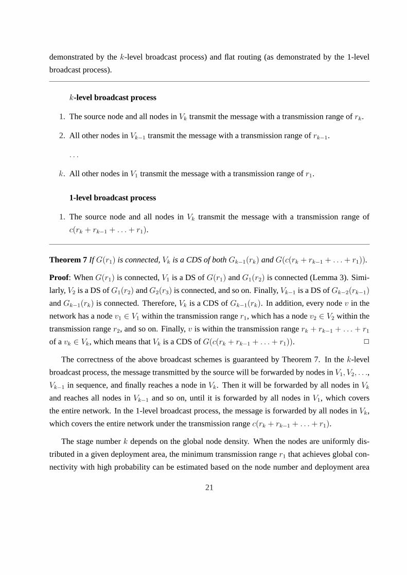
demonstrated by thek-level broadcast process) and flat routing (as demonstrated by the 1-level
broadcast process).
k-level broadcast process
1. The source node and all nodes inVk transmit the message with a transmission range ofrk.
2. All other nodes inVk−1 transmit the message with a transmission range ofrk−1.
. . .
k. All other nodes inV1 transmit the message with a transmission range ofr1.
1-level broadcast process
1. The source node and all nodes inVk transmit the message with a transmission range of
c(rk + rk−1 + . . . + r1).
Theorem 7If G(r1) is connected,Vk is a CDS of bothGk−1(rk) andG(c(rk + rk−1 + . . . + r1)).
Proof: WhenG(r1) is connected,V1 is a DS ofG(r1) andG1(r2) is connected (Lemma 3). Simi-
larly, V2 is a DS ofG1(r2) andG2(r3) is connected, and so on. Finally,Vk−1 is a DS ofGk−2(rk−1)
andGk−1(rk) is connected. Therefore,Vk is a CDS ofGk−1(rk). In addition, every nodev in the
network has a nodev1 ∈ V1 within the transmission ranger1, which has a nodev2 ∈ V2 within the
transmission ranger2, and so on. Finally,v is within the transmission rangerk + rk−1 + . . . + r1
of avk ∈ Vk, which means thatVk is a CDS ofG(c(rk + rk−1 + . . . + r1)). 2
The correctness of the above broadcast schemes is guaranteed by Theorem 7. In thek-level
broadcast process, the message transmitted by the source will be forwarded by nodes inV1, V2, . . .,
Vk−1 in sequence, and finally reaches a node inVk. Then it will be forwarded by all nodes inVk
and reaches all nodes inVk−1 and so on, until it is forwarded by all nodes inV1, which covers
the entire network. In the 1-level broadcast process, the message is forwarded by all nodes inVk,
which covers the entire network under the transmission rangec(rk + rk−1 + . . . + r1).
The stage numberk depends on the global node density. When the nodes are uniformly dis-
tributed in a given deployment area, the minimum transmission ranger1 that achieves global con-
nectivity with high probability can be estimated based on the node number and deployment area
21

r1
u2 v2
r1 r2
v1 u1
Figure 8: The partition problem.
[33]. We assume each node obtains the knowledge of global density before or right after the de-
ployment. When such knowledge is unavailable, or the nodes are not uniformly distributed, an
adaptive density reduction scheme, which will be discussed in the next subsection, can be used to
determine the level of each node based on local information.
5.3 Adaptive DS formation
In the previous discussion, we assume the network is connected under a short transmission range
r1; otherwise, apartition problemexists in the DS formation process. As shown in Figure 8,
when the network is connected under a large transmission range (r2) but disconnected underr1,
the resultant DS may be disconnected even under the large transmission range. The following
connectivity preserving enhancement is applied in stages1, 2, . . . , k − 1 of thek-stage scheme to
avoid the partition problem.
Adaptive DS formation
1. Each nodev determines its initial rangerv using a localized topology control scheme.
2. At each stagei (1 ≤ i ≤ k − 1), all nodesv with rv > ri are automatically added to the DS.
The localized topology control scheme can be any method that determines a minimal trans-
mission range assignment to maintain global connectivity. Theexpanding search regionscheme
[5, 19] can be integrated into the iterative process as follows without extra message overhead: At
each stagei, each node sends at least one message in the DS formation process. By receiving these
messages, each node collects angle-of-arrival (AoA) information of nodes within rangeri, and de-
termines whether its minimal transmission range is larger thanri via cone-based topology control
[19]. When AoA information is unavailable, each node can determine its minimal transmission
range by counting the number of visible neighbors [5], and preserves global connectivity with high
22
probability. When the above enhancement is applied to the network in Figure 8, both nodesu1 and
u2 will be added toV1, maintaining connectivity under ranger2.
Theorem 8If G(rk) is connected, then allVi (1 ≤ i ≤ k) are connected under transmission range
rk.
Proof: Let V0 be the set of all nodes in the network. ObviouslyV0 is connected under transmission
rangerk. AssumeVi−1 (0 ≤ i ≤ k − 1) is connected under transmission rangerk. For any two
nodesu andv in Vi, a pathP : (u = w1, w2, . . . , wl = v) exists inG(rk) such thatwj ∈ Vi−1
for all 1 ≤ j ≤ l. In addition, for each hop(wj, wj+1), eitherd(wi, wj+1) ≤ ri, or bothrwjand
rwj+1are larger thand(wj, wj+1) > ri. For eachwi, let xj bewj if wj ∈ Vi; otherwise, letxj be
a neighbor ofwj in Vi within distanceri. Consider the new pathP ′ : (u = x1, x2, . . . , xl = v).
For each hop(xj, xj+1), if d(wi, wj+1) ≤ ri thend(xj, xj+1) < 3ri < rk/c; otherwise, bothwi
andwj+1 belong toVi and link(xj, xj+1) = (wj, wj+1) exists inG(rk). In both cases,P ′ is a valid
path inG(rk). That is,Vi is connected under rangerk. In the final stage (i = k), a CDS algorithm,
which preserves connectivity, is applied toVk−1. Therefore,Vk is also connected under rangerk.
2
In the adaptive DS formation process, the resultant DS may contain neighboring nodes. That
is, Lemma 2 and the constant approximation ratio and message complexity may not hold. How-
ever, these properties are guaranteed if the cluster formation process is used ink-stage backbone
formation, and each nodev has itsrv ≤ rk−1.
6 Simulation
The efficiency and overhead of both proposed approaches are evaluated via simulations. The
2-level clustering approach (2-Level) and the 1-level flat approach (1-Level) are compared with
several existing ones, including the combination of MP and Rulek (Rule k), two cluster-based
approaches using a mesh (Mesh) and a tree (Tree) to connect clusterheads, and the core-based
approach (Core). In the 2-level approach, the resultant CDS is a dominating set of the subnetwork
consisting of clusterheads. For Core, two versions are considered: one for the DS consisting of
core nodes only (DS) and another for the CDS consisting of both core nodes and non-core nodes
in forwarding sets (CDS). We use node ID as priority in cluster formation to reduce the number
23

of messages (2 messages per node for node ID while 3 for node degree) and energy consumption.
Since Rulek can use node degree as priority with 2 messages per node, node degree is used to im-
prove pruning performance. The core formation process also uses node degree as priority, which
is an approximation of the effective degree (i.e., number of selectors) used in Core.
All approaches are simulated on a custom simulator. In order to generate a random network,
n nodes are randomly placed in a100 × 100 square region to form a unit disk graph using a
transmission range ofr. For Rulek, Mesh, Tree, and Core,r is set to 24. For the 2-level approach,
r is 8 in the first (clustering) stage and 24 in the second (pruning) stage. For the 1-level approach,
r is 6 in the first stage and 18 in the second stage. Each simulation is repeated until the90%
confidence interval is within±1%.
Efficiency: We compare the efficiency of different approaches in terms of the size of the resultant
CDS, and the energy consumption in the corresponding broadcast process. Figure 9(a) shows the
size of the resultant backbone in different approaches. In Rulek, the CDS size increases rapidly as
the network size (n) grows. The size of the DS in Core is very close to the size of the CDS in Rule
k, and the size of the CDS in Core is much larger than in other approaches. In other words, neither
Rulek nor Core is very efficient in dense networks. In other approaches, the CDS sizes are barely
affected by the network density. Forn ≥ 500, increasingn can cause only a slight difference in the
CDS sizes. The CDS sizes in those approaches depend on the number of clusterheads, which has a
constant upper bound in a region with a fixed size. Among those approaches, the 1-level approach
is about 20% better than the mesh approach, and the 2-level approach is about 30% better than the
tree approach. Although the 2-level approach produces a smaller CDS than the 1-level approach,
it also requires a more complex routing scheme.
Figure 9(b) shows the broadcast cost of different approaches in terms of the total transmission
power. In the 2-level approach, all marked nodes transmit the message with the normal trans-
mission ranger, and all unmarked nodes transmit with a transmission range ofr/3. In other
approaches, all backbone nodes transmit with the normal transmission range. A commonly used
energy model [12] can be stated ase = αrk + β, wheree is the energy consumption,k is usu-
ally between 2 and 4, andα, β are device specific constants. Here we usek = 2, α = 0.001,
andβ = 0. The result is quite similar to the case of CDS size. The only difference is that, after
considering the energy consumption of unmarked clusterheads, the broadcast cost of the 2-level
approach is slightly higher than that of the tree approach, but still significantly lower than the other
24

20
40
60
80
100
120
140
160
180
100 200 300 400 500 600 700 800 900 1000
Siz
e of
dom
inat
ing
set
Number of hosts
Rule kCluster (Mesh)Cluster (Tree)
Core (DS)Core (CDS)
1-Level2-Level
(a) Size of CDS
0
10
20
30
40
50
60
70
80
90
100
100 200 300 400 500 600 700 800 900 1000
Ene
rgy
cons
umpt
ion
Number of hosts
Rule kCluster (Mesh)Cluster (Tree)
Core (DS)Core (CDS)
1-Level2-Level
LMST
(b) Broadcast cost
2
4
6
8
10
100 200 300 400 500 600 700 800 900 1000
Num
ber
of r
ound
s
Number of hosts
Rule kCluster (Mesh)Cluster (Tree)
Core (DS)Core (CDS)
1-Level2-Level
(c) Number of rounds
0
500
1000
1500
2000
2500
100 200 300 400 500 600 700 800 900 1000
Ene
rgy
cons
umpt
ion
Number of hosts
Rule kCluster (Mesh)Cluster (Tree)
Core (DS)Core (CDS)
1-Level2-Level
(d) Energy consumption on the senders’ side.
Figure 9: Simulation results.
25
approaches. For comparison, a topology control algorithm based on local minimal spanning tree
(LMST) [20] is also simulated, assuming all nodes forward the broadcast packet with a small trans-
mission power. The broadcast cost of LMST is about50% of the best CDS algorithm. Note that
the relative performance of a topology control scheme and a CDS-based scheme depends on the
underlying energy model. The topology control approach is better with largeα andk. The CDS
approach is superior with a largeβ.
Overhead: Two types of overhead are considered in our comparison: time, and energy. We
measure the time cost in terms of the number of rounds of message exchange. Rulek completes in
2 rounds. In Core, core formation requires 3 rounds, and the designation of forwarding sets needs
2 extra rounds. In other approaches, more rounds are required to obtain a stable cluster structure.
After clusterhead formation, both 1-level and 2-level approaches require two extra rounds to apply
MP and Rulek. The mesh approach also requires two extra rounds: one for gathering neighboring
cluster information, and another for gateway designation. The tree approach has two extra phases:
root election and tree construction via flooding. Here we assume that the root is pre-selected and
consider only the flooding cost. As shown in Figure 9(c), Rulek and Core have the lowest cost,
and the tree approach has the highest cost. The 1-level, 2-level, and mesh approaches have similar
costs. That is, both proposed approaches achieve higher efficiency than the mesh approach without
extra time cost.
Considering the different transmission powers for different transmission ranges (r), the en-
ergy consumption of the two proposed approaches is much lower than the other approaches. In
the clustering stage of the two proposed approaches, packets are sent to a smaller transmission
range, which is only1/3 or 1/4 of the normal transmission range. Figure 9(d) shows the energy
consumption during the backbone formation process. The energy consumption of both proposed
approaches is a fraction of the other approaches.
Simulation results can be summarized as follows: (1) Both proposed approaches produce a
smaller CDS than Rulek, Core and the mesh approach. (2) Both proposed approaches have a
converging speed similar to that of the mesh approach, which is significantly faster than the tree
approach. (3) Both proposed approaches have significantly lower energy consumption than Rule
k, Core, mesh, and tree approaches.
26

7 Conclusions
We have proposed a novel approach to address the communication and computation complexity
issue in many local CDS construction algorithms. This approach is based on a special method
of merging the clustering approach with the use of different transmission ranges. Wu and Li’s
marking process has been extended as an illustration of the proposed approach. Specifically, the
clustering algorithm is applied using a short transmission range to reduce the density of a MANET.
Clusterheads form a connected dominating set (CDS) using a long transmission range, which can
be used as a backbone of the MANET. Wu and Li’s marking process is then applied to the CDS to
reduce the number of backbone nodes.
Two routing schemes have been proposed based on the backbone formation approach. In the
2-level hierarchical approach, messages are transmitted using a long transmission range by a small
set of selected clusterheads that form the upper level backbone, and a short transmission range by
other clusterheads the form the lower level backbone. In the 1-level flat approach, messages are
transmitted by only selected clusterheads using a long transmission range. The 2-level approach is
more energy efficient, as fewer nodes use the long transmission range. The 1-level approach has
a simpler routing process and uses fewer backbone nodes. Both analytic and simulation studies
confirm the effectiveness of the proposed approaches, especially in dense networks.
We have further extended the proposed approach to a general framework that uses other exist-
ing clustering and CDS formation algorithms, including the core-based approach [13, 28] and MPR
[1, 26], for tradeoffs between the number of backbone nodes and various formations’ overhead. In
very dense networks, we have proposed multi-stage density reduction, which uses different trans-
mission ranges in different stages of the backbone formation process to control the communication
and computation cost of each stage. Our future work will focus on other applications of the virtual
backbone, including topology management in MANETs and point and area coverage in sensor
networks.
References
[1] C. Adjih, P. Jacquet, and L. Viennot. Computing connected dominated sets with multipoint
relays. Technical Report 4597, INRIA-Rapport de recherche, Oct. 2002.
27

[2] K. Alzoubi, X. Y. Li, Y. Wang, P. J. Wan, and O. Frieder. Geometric spanners for wireless
ad hoc networks.IEEE Transactions on Parallel and Distributed Systems, 14(5):408–421,
2003.
[3] K. M. Alzoubi, P. J. Wan, and O. Frieder. Message-optimal connected dominating sets in
mobile ad hoc networks. InProc. of MobiHoc, pages 157–164, June 2002.
[4] K. M. Alzoubi, P. J. Wan, and O. Frieder. New distributed algorithm for connected dominating
set in wireless ad hoc networks. InProc. of HICSS-35, page 297, Jan. 2002.
[5] D. Blough, M. Leoncini, G. Resta, and P. Santi. The K-Neigh protocol for symmetric topol-
ogy control in ad hoc networks. InProc. of MobiHoc, pages 141–152, June 2003.
[6] M. Burkhard, P. Rickenbach, R. Wattenhofer, and A. Zollinger. Does topology control reduce
interference. InProc. of MobiHoc, 2004.
[7] J. Cartigny, D. Simplot, and I. Stojmenovic. Localized minimum-energy broadcasting in
ad-hoc networks. InProc. of Infocom, pages 2210–2217, 2003.
[8] B. Chen, K. Jamieson, H. Balakrishnan, and R. Morris. SPAN: an energy-efficient coor-
dination algorithm for topology maintenance in ad hoc wireless networks.ACM Wireless
Networks Journal, 8(5):481–494, 2002.
[9] A. Clementi, P. Crescenzi, P. Penna, G. Rossi, and P. Vocca. On the complexity of computing
minimum energy consumption broadcast subgraphs. InProc. of STACS, 2001.
[10] F. Dai and J. Wu. Distributed dominant pruning in ad hoc wireless networks. InProc. of ICC,
volume 1, pages 353–357, May 2003.
[11] D. Dubhashi, A. Mei, A. Panconesi, J. Radhakrishnan, and A. Srinivasan. Fast distributed
algorithms for (weakly) connected dominating sets and linear-size skeletons. InProceedings
of ACM-SIAM SODA, pages 717–724, Jan. 2003.
[12] L. M. Feeney. An energy-consumption model for performance analysis of routing protocols
for mobile ad hoc networks.Mobile Networks and Applications, 6(3):239–249, June 2001.
[13] J. Gao, L. J. Guibas, J. Hershberger, L. Zhang, and A. Zhu. Discrete mobile centers. In
Symposium on Computational Geometry, pages 188–196, 2001.
28

[14] S. Guha and S. Khuller. Approximation algorithms for connected dominating sets.Algorith-
mica, 20(4):374–387, Apr. 1998.
[15] L. Jia, R. Rajaraman, and T. Suel. An efficient distributed algorithm for constructing small
dominating sets. InProceedings of ACM PODC, pages 33–42, Aug. 2001.
[16] F. Kuhn, T. Moscibroda, and R. Wattenhofer. Initializing newly deployed ad hoc and sensor
networks. InProc. of MobiCom, pages 260–274, Sep./Oct. 2004.
[17] F. Kuhn, T. Moscibroda, and R. Wattenhofer. What cannot be computed locally! InProc. of
PODC, July 2004.
[18] F. Kuhn and R. Wattenhofer. Constant-time distributed dominating set approximation. In
Proc. of PODC, 2003.
[19] L. Li, J. Y. Halpern, V. Bahl, Y. M. Wang, and R. Wattenhofer. Analysis of a cone-based
distributed topology control algorithm for wireless multi-hop networks. InProc. of PODC,
pages 264–273, Aug. 2001.
[20] N. Li, J. C. Hou, and L. Sha. Design and analysis of an mst-based topology control algorithm.
In Proc. of Infocom, volume 3, pages 1702–1712, Mar./Apr. 2003.
[21] X. Y. Li, Y. Wang, P. J. Wan, W. Z. Song, and O. Frieder. Localized low-weight graph and its
application in wireless ad hoc networks. InProc. of Infocom, 2004.
[22] H. Lim and C. Kim. Flooding in wireless ad hoc networks.Computer Communications
Journal, 24(3-4):353–363, 2001.
[23] C. R. Lin and M. Gerla. Adaptive clustering for mobile wireless networks.IEEE Journal on
Selected Areas in Communications, 15(7):1265–1275, 1996.
[24] W. Lou and J. Wu. On reducing broadcast redundancy in ad hoc wireless networks.IEEE
Transactions on Mobile Computing, 1(2):111–122, Apr.-June 2002.
[25] W. Peng and X. Lu. On the reduction of broadcast redundancy in mobile ad hoc networks. In
Proc. of MobiHoc, pages 129–130, June 2000.
[26] A. Qayyum, L. Viennot, and A. Laouiti. Multipoint relaying for flooding broadcast message
in mobile wireless networks. InProc. of HICSS-35, page 298, Jan. 2002.
29

[27] V. Rodoplu and T. H. Meng. Minimum energy mobile wireless networks.IEEE Journal of
Selected Areas in Communications, 17(8):1333–1344, Aug. 1999.
[28] P. Sinha, R. Sivakumar, and V. Bharghavan. Enhancing ad hoc routing with dynamic virtual
infrastructures. InProc. of Infocom, pages 1763–1772, Apr. 2001.
[29] I. Stojmenovic, S. Seddigh, and J. Zunic. Dominating sets and neighbor elimination based
broadcasting algorithms in wireless networks.IEEE Transactions on Parallel and Distributed
Systems, 13(1):14–25, Jan. 2002.
[30] J. Sucec and I. Marsic. An efficient distributed network-wide broadcast algorithm for mobile
ad hoc networks. CAIP Technical Report 248, Rutgers University, Sep. 2000.
[31] Y. C. Tseng, S. Y. Ni, Y. S. Chen, and J. P. Sheu. The broadcast storm problem in a mobile
ad hoc network.Wireless Networks, 8(2-3):153–167, Mar.-May 2002.
[32] P. J. Wan, G. Calinescu, X. Y. Li, and O. Frieder. Minimum-energy broadcast routing in static
ad hoc wireless networks.ACM Wireless Networks, 2002.
[33] P. J. Wan and C. W. Yi. Asympotic critical transmission radius and critical neighbor number
for k-connectivity in wireless ad hoc networks. InProc. of MobiHoc, May 2004.
[34] W. Z. Song Y. Wang, , X. Y. Li, and O. Frieder. Localized algorithms for energy efficient
topology control in wireless ad hoc networks. InProc. of MobiHoc, 2004.
[35] J. E. Wieselthier, G. D. Nguyen, and A. Ephremides. On constructing minimum spanning
trees ink-dimensional spaces and related problems. InProc. of Infocom, pages 585–594,
2000.
[36] J. Wu and F. Dai. A generic distributed broadcast scheme in ad hoc wireless networks. In
Proc. of ICDCS, pages 460–468, May 2003.
[37] J. Wu and H. Li. On calculating connected dominating set for efficient routing in ad hoc
wireless networks. InProc. of DialM, pages 7–14, 1999.
[38] J. Wu and W. Lou. Forward-node-set-based broadcast in clustered mobile ad hoc networks.
Wireless Communications and Mobile Computing, special issue on Algorithmic, Geometric,
Graph, Combinatorial, and Vector, 3(2):155–173, 2003.
30