Embed Size (px)
Citation preview

VIRGINIA POLYTECHNIC INSTITUTE & STATE UNIVERSITY
MOBILE & PORTABLE RADIO RESEARCH GROUPMPRG
VIRGINIA POLYTECHNIC INSTITUTEAND STATE UNIVERSITY
TechVirginia
1 8 7 2
Introduction to UWB:Impulse Radio for Radar and
Wireless CommunicationsDr. Jeffrey Reed
Dr. R. Michael BuehrerDong S. Ha
E-mail: {reedjh, buehrer, ha}@vt.eduWeb: www.mprg.org

VIRGINIA POLYTECHNIC INSTITUTE & STATE UNIVERSITY
MOBILE & PORTABLE RADIO RESEARCH GROUPMPRG
VIRGINIA POLYTECHNIC INSTITUTEAND STATE UNIVERSITY
TechVirginia
1 8 7 2
Overview
• What is Ultra Wideband (UWB)?• Applications of UWB• What’s Commercially Available?• How do you build a UWB radio?• Channel models for UWB• UWB radar and sensors• New FCC regulations regarding UWB• UWB research at Virginia Tech• Research opportunities for UWB applied to automobiles

VIRGINIA POLYTECHNIC INSTITUTE & STATE UNIVERSITY
MOBILE & PORTABLE RADIO RESEARCH GROUPMPRG
VIRGINIA POLYTECHNIC INSTITUTEAND STATE UNIVERSITY
TechVirginia
1 8 7 2
Impulse Radio
• Impulse Radio (IR): the use of extremely short duration pulses (sub-nanosecond) instead of continuous waves to transmit information.
• The pulse directly generates a very wide instantaneous bandwidth signal according to the time-scaling properties of the Fourier transform relationship between time and frequency. (Occupied BW >> Information Bandwidth)
• Very low duty cycle (on the order 1/100, 1/1000 or less)

VIRGINIA POLYTECHNIC INSTITUTE & STATE UNIVERSITY
MOBILE & PORTABLE RADIO RESEARCH GROUPMPRG
VIRGINIA POLYTECHNIC INSTITUTEAND STATE UNIVERSITY
TechVirginia
1 8 7 2
UWB Definition
• Common Definitions– UWB: Fractional bandwidth = (fH - fL)/fc > 25% or total BW > 1.5 GHz.– Narrowband: (fH - fL)/fc < 1%.
• FCC Definition of UWB– Fractional bandwidth (measured at the -10dB points),
(fH - fL)/fc, > 20% or total BW > 500 MHz.

VIRGINIA POLYTECHNIC INSTITUTE & STATE UNIVERSITY
MOBILE & PORTABLE RADIO RESEARCH GROUPMPRG
VIRGINIA POLYTECHNIC INSTITUTEAND STATE UNIVERSITY
TechVirginia
1 8 7 2
Advantages of UWB
• Low Power Consumption• Low cost: nearly "all-digital", with minimal RF electronics.• A low probability of detection (LPD) signature• Integrated Services: Communications and Radar.• Communications
– Extremely high data rate performance in multi-user network applications. – Relativity immune to multipath cancellation effects as observed in
mobile and in-building environments. – Low interference to existing narrowband systems due to low power
spectral density.

VIRGINIA POLYTECHNIC INSTITUTE & STATE UNIVERSITY
MOBILE & PORTABLE RADIO RESEARCH GROUPMPRG
VIRGINIA POLYTECHNIC INSTITUTEAND STATE UNIVERSITY
TechVirginia
1 8 7 2
Why is Ultra-wideband Useful?
• Potential Applications– Wireless Communications Systems
• Local and Personal Area Networks (LAN/PAN)• Roadside Info-station• Short range radios• Military Communications
– Radar and Sensing• Vehicular Radar • Ground Penetrating Radar (GPR)• Through Wall Imaging (Police, Fire, Rescue)• Medical Imaging• Surveillance
– Location Finding• Precision location (inventory, GPS aid)

VIRGINIA POLYTECHNIC INSTITUTE & STATE UNIVERSITY
MOBILE & PORTABLE RADIO RESEARCH GROUPMPRG
VIRGINIA POLYTECHNIC INSTITUTEAND STATE UNIVERSITY
TechVirginia
1 8 7 2
Advantages of UWB (con’t)
• Radar– Improved range measurement accuracy.– Improved object identification (greater resolution).– Reduced radar effects due to passive interference (rain, mist, aerosols,
metalized strips).– Improved stability observing targets at low elevation angles.– More uniform radar cross section (RCS), due to reduced interference
from individual parts of the target.– Narrow antenna pattern achievable by changing radiated signal.– Decreased detectability by ‘hostile’ interceptor
reference: Immoreev, I.I., Fedotov, D.V. “Ultra Wideband Radar Systems: Advantages and Disadvantages”. Proc. of theIEEE Conference on Ultra Wideband Systems and Technology 2002.

VIRGINIA POLYTECHNIC INSTITUTE & STATE UNIVERSITY
MOBILE & PORTABLE RADIO RESEARCH GROUPMPRG
VIRGINIA POLYTECHNIC INSTITUTEAND STATE UNIVERSITY
TechVirginia
1 8 7 2
Networking
• Personal Area Networking (PAN), connecting cell phones, laptops, PDAs, cameras, MP3 players.– Much higher data rates than Bluetooth or 802.11.
• Can be integrated into automotive in-car services and entertainment.– Download driving directions from PDA/laptop for use by on-board
navigation system using GPS.– Download music and videos for passenger entertainment.

VIRGINIA POLYTECHNIC INSTITUTE & STATE UNIVERSITY
MOBILE & PORTABLE RADIO RESEARCH GROUPMPRG
VIRGINIA POLYTECHNIC INSTITUTEAND STATE UNIVERSITY
TechVirginia
1 8 7 2
Information Services
Info-station concept• Road side ‘markers’ containing UWB transmitters.
– Short burst of very high rate data (100s of Mbps for 1-3 sec at a time)– Messages could contain road conditions, construction, weather advisories.– Allow for emergency assistance communication.

VIRGINIA POLYTECHNIC INSTITUTE & STATE UNIVERSITY
MOBILE & PORTABLE RADIO RESEARCH GROUPMPRG
VIRGINIA POLYTECHNIC INSTITUTEAND STATE UNIVERSITY
TechVirginia
1 8 7 2
Information Services
Info-station concept• Service station
– While, pumping gas, latest video/movie or other content could purchased for download and viewing later at home or by passengers in the vehicle.

VIRGINIA POLYTECHNIC INSTITUTE & STATE UNIVERSITY
MOBILE & PORTABLE RADIO RESEARCH GROUPMPRG
VIRGINIA POLYTECHNIC INSTITUTEAND STATE UNIVERSITY
TechVirginia
1 8 7 2
Vehicular Radar
Collision Avoidance/Detection
• Driver aid/alert to avoid collisions.
• Aid for airbag/restraint deployment
• Resolution to distinguish cars/people/animals/poles on or near road
Image from presentation by Prof. Dr. Knoll of SARA at 2nd Workshop on introduction of Ultra Wideband Services in Europe

VIRGINIA POLYTECHNIC INSTITUTE & STATE UNIVERSITY
MOBILE & PORTABLE RADIO RESEARCH GROUPMPRG
VIRGINIA POLYTECHNIC INSTITUTEAND STATE UNIVERSITY
TechVirginia
1 8 7 2
Collision Avoidance Example
• From Multispectral Solutions
• C-band UWB backup sensor(not FCC vehicular radar band)– 600 MHz instantaneous BW– High-speed, dual tunnel detector– Range
• 1 - 50 feet against human target• 1 - 200 feet against pickup truck
– Clutter resistant– Extremely low false alarm rate
Reference: Fontana, R. “Ultra Wideband Technology - The Wave of the Future?” ITC/USA 2000, Oct. 2000.

VIRGINIA POLYTECHNIC INSTITUTE & STATE UNIVERSITY
MOBILE & PORTABLE RADIO RESEARCH GROUPMPRG
VIRGINIA POLYTECHNIC INSTITUTEAND STATE UNIVERSITY
TechVirginia
1 8 7 2
Vehicular Radar
Road Conditions Sensing• UWB radar has the resolution to sense road conditions (i.e. potholes, dips,
bumps, gravel vs. pavement).• Information to dynamically adjust suspension, braking, and other drive
systems.

VIRGINIA POLYTECHNIC INSTITUTE & STATE UNIVERSITY
MOBILE & PORTABLE RADIO RESEARCH GROUPMPRG
VIRGINIA POLYTECHNIC INSTITUTEAND STATE UNIVERSITY
TechVirginia
1 8 7 2
Trinity Chip Set
• Xtreme Spectrum Inc. has released Trinity chip set.
• Data rates of 25, 50, 75 and 100 Mbps.
• MAC, baseband processor, RF transceiver, LNA, and antenna
• Streaming video applications.• Wireless Fast Ethernet, USB2, and
1394.
VIRGINIA POLYTECHNIC INSTITUTE & STATE UNIVERSITY
MOBILE & PORTABLE RADIO RESEARCH GROUPMPRG
VIRGINIA POLYTECHNIC INSTITUTEAND STATE UNIVERSITY
TechVirginia
1 8 7 2
PulsON ASICs
• Time Domain Corporation is marketing PulsON family of UWB silicon products.
• Indoor wireless networking, 100's Mbps• Indoor personnel and asset tracking systems.• Precision measurement systems for surveying
and measurement.• Radar, 20 cm accuracy• Through wall sensing.• Industrial sensing for robotic controls.• Automotive sensing for collision avoidance.• Security bubbles for home and industrial
security systems.Image from Kelley, D., Reinhardt, S., Stanley, R., Einhorn, M. “PulsON Second Generation Timing Chip; Enabling UWB Through Precise Timing”, Proc. of theIEEE Conference on Ultra Wideband Systems and Technology 2002.

VIRGINIA POLYTECHNIC INSTITUTE & STATE UNIVERSITY
MOBILE & PORTABLE RADIO RESEARCH GROUPMPRG
VIRGINIA POLYTECHNIC INSTITUTEAND STATE UNIVERSITY
TechVirginia
1 8 7 2
UWB Products, Communications
MultiSpectral Solutions Inc.– Communications, Mobile ad hoc Network (MANET)– 128 kbps voice, 115.2 kbps data or 1.544 Mbps (T1)– Range: 1-2 km (node-to-node) with omni antennas
Reference: Fontana, R. “Ultra Wideband Technology - The Wave of the Future?” ITC/USA 2000, Oct. 2000.
VIRGINIA POLYTECHNIC INSTITUTE & STATE UNIVERSITY
MOBILE & PORTABLE RADIO RESEARCH GROUPMPRG
VIRGINIA POLYTECHNIC INSTITUTEAND STATE UNIVERSITY
TechVirginia
1 8 7 2
UWB Products, Location
MultiSpectral Solutions Inc.• High resolution, geolocation
system, 3-D positioning– Sub-foot resolution– Range
• Up to 2 km outdoors• Up to 300 feet indoors
– UWB Geopositioning Example
Reference: Fontana, R. “Ultra Wideband Technology - The Wave of the Future?” ITC/USA 2000, Oct. 2000.
Reference: Fontana, R. “Ultra Wideband Technology - The Wave of the Future?” ITC/USA 2000, Oct. 2000.

VIRGINIA POLYTECHNIC INSTITUTE & STATE UNIVERSITY
MOBILE & PORTABLE RADIO RESEARCH GROUPMPRG
VIRGINIA POLYTECHNIC INSTITUTEAND STATE UNIVERSITY
TechVirginia
1 8 7 2
UWB Products, Location
Aether Wire & Locations (AWL) – Development of pager-sized units that are capable of localization to
submeter accuracy over 100-meter distances in networks of up to a few hundred localizers.
• A prototype localizer consists of two chips
Actual size TX (Driver2) RX (Aether5)with Dime Reference: http://www.aetherwire.com/

VIRGINIA POLYTECHNIC INSTITUTE & STATE UNIVERSITY
MOBILE & PORTABLE RADIO RESEARCH GROUPMPRG
VIRGINIA POLYTECHNIC INSTITUTEAND STATE UNIVERSITY
TechVirginia
1 8 7 2
UWB Products
Pulse~Link• Mobile wireless and geographic positioning.
– Hardware / software platform solution implemented in a custom microchip.
– Not available until 2003.
• Demonstrated UWB over existing cable television networks.– Claims to double capacity.– Not available until Q4 2002.
Reference: http://www.pulse-link.net

VIRGINIA POLYTECHNIC INSTITUTE & STATE UNIVERSITY
MOBILE & PORTABLE RADIO RESEARCH GROUPMPRG
VIRGINIA POLYTECHNIC INSTITUTEAND STATE UNIVERSITY
TechVirginia
1 8 7 2
Baseband UWB
τ
t
500 ps 1 2 3 4 GHz
Amplitude
Gaussian MonocyclePulse Spectrum EnvelopLine at Pulse Repition Rate
• UWB pulse transmitted directly• Has no “carrier or center frequency”• Requires wideband antennas• Spectrum control difficult (occupies frequencies from near DC to a few GHz)• Potential problem with GPS and licensed bands
(and therefore does NOT meet FCC spectral masks)

VIRGINIA POLYTECHNIC INSTITUTE & STATE UNIVERSITY
MOBILE & PORTABLE RADIO RESEARCH GROUPMPRG
VIRGINIA POLYTECHNIC INSTITUTEAND STATE UNIVERSITY
TechVirginia
1 8 7 2
Bandpass UWB
• Pulses are run through a bandpass filter• Center frequency controlled by filter center frequency.
– Can also be modulated onto carrier for higher frequency bands• Pulse shape and spectrum controlled by filter impulse response and to a
lesser degree by input pulse shape
TH-PPM UWB transmitter

VIRGINIA POLYTECHNIC INSTITUTE & STATE UNIVERSITY
MOBILE & PORTABLE RADIO RESEARCH GROUPMPRG
VIRGINIA POLYTECHNIC INSTITUTEAND STATE UNIVERSITY
TechVirginia
1 8 7 2
UWB System Example
Impulse Radio using Time Hopping• Impulse Radio
– Very low duty cycle (Tf / Tp > 100)– ‘Pulse train’– One pulse transmitted per frame (Tf )
uniform pulse train (no modulation, no dithering)

VIRGINIA POLYTECHNIC INSTITUTE & STATE UNIVERSITY
MOBILE & PORTABLE RADIO RESEARCH GROUPMPRG
VIRGINIA POLYTECHNIC INSTITUTEAND STATE UNIVERSITY
TechVirginia
1 8 7 2
UWB System
• Received signal model for the kth user:
– Time hopping, modulation, and pulse shape affect parameters.
( )[ ]
( ) ( )[ ]( )( )/ /( )
j N ss
k k k kf j c j N
js t A p t jT c T dδ= − − −∑
Reference: Scholtz, R.A. “Multiple Access with Time-Hopping Impulse Modulation”. In Proc. of IEEE MILCOM '93, Communications on the Move, vol, 2, 1993, pp. 447-450 vol.2

VIRGINIA POLYTECHNIC INSTITUTE & STATE UNIVERSITY
MOBILE & PORTABLE RADIO RESEARCH GROUPMPRG
VIRGINIA POLYTECHNIC INSTITUTEAND STATE UNIVERSITY
TechVirginia
1 8 7 2
Pulse Train
• UWB systems typically use many pulse repetitions (100s) to represent each data symbol.
• A uniform pulse train has spectral lines present (not a smooth spectrum).
• For multiple access this could also lead to catastrophic collisions.
• Time-hopping is one possible solution….
0 2 4 6 8 10 12 14 16 18 20-1
-0.8
-0.6
-0.4
-0.2
0
0.2
0.4
0.6
0.8
1
Time (ns)
Am
plitu
de /
Nor
mal
ized
to A
Uniform Pulse Train Spacing
Uniform Pulse Train Spacing
0 2 4 6 8 10 12
10-8
10-6
10-4
10-2
100
Frequency (GHz)
Am
plitu
de /
Nor
mal
ized
to 1
Gaussian Monocycle and Gaussian Monocycle Pulse Train in Frequency Domain
Gaussian Monocycle Monocycle Pulse Train
VIRGINIA POLYTECHNIC INSTITUTE & STATE UNIVERSITY
MOBILE & PORTABLE RADIO RESEARCH GROUPMPRG
VIRGINIA POLYTECHNIC INSTITUTEAND STATE UNIVERSITY
TechVirginia
1 8 7 2
Time Hopping
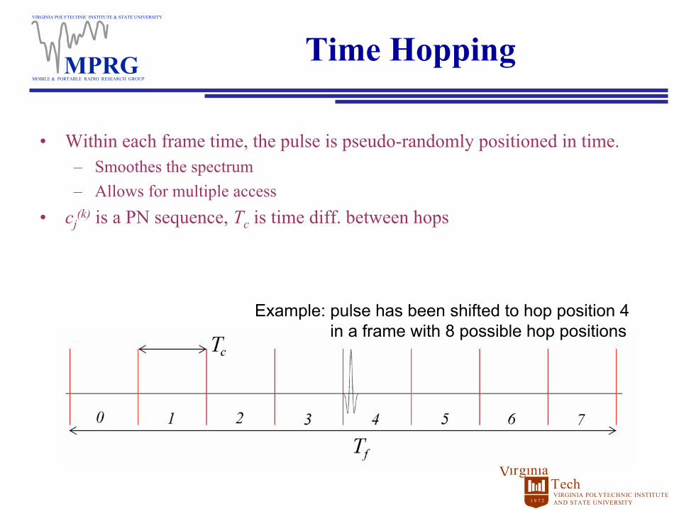
• Within each frame time, the pulse is pseudo-randomly positioned in time.– Smoothes the spectrum– Allows for multiple access
• cj(k) is a PN sequence, Tc is time diff. between hops
Example: pulse has been shifted to hop position 4 in a frame with 8 possible hop positions

VIRGINIA POLYTECHNIC INSTITUTE & STATE UNIVERSITY
MOBILE & PORTABLE RADIO RESEARCH GROUPMPRG
VIRGINIA POLYTECHNIC INSTITUTEAND STATE UNIVERSITY
TechVirginia
1 8 7 2
Spectrum of Random/Pseudorandom Time-Hopping
0 2 4 6 8 10 12
10-8
10-6
10-4
10-2
100
Frequency (GHz)
Am
plitu
de /
Nor
mal
ized
to 1
Gaussian Monocycle and Gaussian Monocycle Pulse Train in Frequency Domain
Gaussian Monocycle Monocycle Pulse Train

VIRGINIA POLYTECHNIC INSTITUTE & STATE UNIVERSITY
MOBILE & PORTABLE RADIO RESEARCH GROUPMPRG
VIRGINIA POLYTECHNIC INSTITUTEAND STATE UNIVERSITY
TechVirginia
1 8 7 2
Direct Sequence, DS-UWB
• Similar to conventional CDMA carrier based radios.• PN sequence is multiplied by an impulse sequence at a duty
cycles approaching a sinusoidal carrier.• Channelization and modulation are provided as in CDMA.• The chipping rate is some fraction, 1/N, of the center frequency.
– Change the chipping rate, trade total power for spectral shape
Reference: Siwiak, K., “Ultra-Wide Band Radio: A New PAN and positioning Technology”, IEEE Vehicular Technology Society News, February 2002, pp. 4-9.

VIRGINIA POLYTECHNIC INSTITUTE & STATE UNIVERSITY
MOBILE & PORTABLE RADIO RESEARCH GROUPMPRG
VIRGINIA POLYTECHNIC INSTITUTEAND STATE UNIVERSITY
TechVirginia
1 8 7 2
UWB Communications
Modulation• Pulse position modulation (PPM)
– Binary/M-ary
• Bipolar Signaling (BPSK)• Pulse Amplitude Modulation (PAM)• On/Off Keying (OOK)• Orthogonal pulse shapes
– Hermite Polynomials
• Combinations of the above

VIRGINIA POLYTECHNIC INSTITUTE & STATE UNIVERSITY
MOBILE & PORTABLE RADIO RESEARCH GROUPMPRG
VIRGINIA POLYTECHNIC INSTITUTEAND STATE UNIVERSITY
TechVirginia
1 8 7 2
Modulation Examples
• Pulse Position Modulation (PPM)– The data is carried in the ‘fine’ time shift of the pulse.– M-ary PPM possible (higher M can mean fewer time hop positions for a given
frame time)– Orthogonal (or better depending on pulse shape)
Example: 4-ary PPM,with data 01

VIRGINIA POLYTECHNIC INSTITUTE & STATE UNIVERSITY
MOBILE & PORTABLE RADIO RESEARCH GROUPMPRG
VIRGINIA POLYTECHNIC INSTITUTEAND STATE UNIVERSITY
TechVirginia
1 8 7 2
Modulation Examples
• Bipolar signaling– The data is carried in the polarity of
the pulse.– Antipodal (very energy efficient)
• Biorthogonal signaling– Combination of PPM and bipolar
signaling– M-ary biothogonal has M/2
possible PPM shiftExample: 4-ary
biorthogonal, with data 10
Example: bipolarwith data 1

VIRGINIA POLYTECHNIC INSTITUTE & STATE UNIVERSITY
MOBILE & PORTABLE RADIO RESEARCH GROUPMPRG
VIRGINIA POLYTECHNIC INSTITUTEAND STATE UNIVERSITY
TechVirginia
1 8 7 2
Modulation Examples
• PAM– Very poor energy efficiency.
• OOK– Simple implementation.– Poor energy efficiency.
Example: OOK with data seq: 1, 0, 0, 1
Example: 4-ary PAM with data seq: 01, 11, 00, 10

VIRGINIA POLYTECHNIC INSTITUTE & STATE UNIVERSITY
MOBILE & PORTABLE RADIO RESEARCH GROUPMPRG
VIRGINIA POLYTECHNIC INSTITUTEAND STATE UNIVERSITY
TechVirginia
1 8 7 2
UWB Correlation Receiver
• The received signal is correlated with the expected received pulse (may differ from the transmitted pulse due to distortion by the antennas and channel).
• Simple design, less RF hardware than narrowband receivers.
UWB correlation receiver

VIRGINIA POLYTECHNIC INSTITUTE & STATE UNIVERSITY
MOBILE & PORTABLE RADIO RESEARCH GROUPMPRG
VIRGINIA POLYTECHNIC INSTITUTEAND STATE UNIVERSITY
TechVirginia
1 8 7 2
UWB Rake Receiver
• UWB signals have as many as 30 resolvable multipathcomponents.
• Energy can be combined using a Rake receiver to improve performance.
• Each path has very small energy, difficult to perform accurate channel estimation for each path.– Each path could have experienced different distortion.– Complexity to estimate 30 different paths can be high.
• Can complexity reduced and still exploit multipath?– Non-coherent versus coherent energy combining.

VIRGINIA POLYTECHNIC INSTITUTE & STATE UNIVERSITY
MOBILE & PORTABLE RADIO RESEARCH GROUPMPRG
VIRGINIA POLYTECHNIC INSTITUTEAND STATE UNIVERSITY
TechVirginia
1 8 7 2
Pulse Shape
• The received pulse shape is dependant on the pulse generation, pulse shaping filter and the antenna responses.
• Example Pulse shapes– Gaussian pulse
– Gaussian monopulse (monocycle)(1st derivative of Gaussian pulse)
– Gaussian doublet(2nd derivative of Gaussian pulse)
– Doublet with separated monopulses• (Aether Wire & Locations’ Localizer)

VIRGINIA POLYTECHNIC INSTITUTE & STATE UNIVERSITY
MOBILE & PORTABLE RADIO RESEARCH GROUPMPRG
VIRGINIA POLYTECHNIC INSTITUTEAND STATE UNIVERSITY
TechVirginia
1 8 7 2
Channel Measurement
• Propagation for communications and radar system.• Interference to narrowband communications and other
electronics.• Resistance of UWB to interference.
• Must understand channel effects to fully exploit the unique properties of UWB.– Affects communications waveform/modulation/receiver design.– Material/shape/range of objects affect radar signature.

VIRGINIA POLYTECHNIC INSTITUTE & STATE UNIVERSITY
MOBILE & PORTABLE RADIO RESEARCH GROUPMPRG
VIRGINIA POLYTECHNIC INSTITUTEAND STATE UNIVERSITY
TechVirginia
1 8 7 2
Channel Measurement Environments
• Indoor– Within a room (LOS, NLOS), Between
rooms/floors, Down hallways– Will investigate the impact of
• distance• Rx/Tx Antenna Height• antenna polarization
• Indoor-to-outdoor• Outdoor
– Campus environment– Rural, Hilly, Impact of foliage– Urban– “Low altitude”– Impact of distance (up to ~1km)– Mobility (Pedestrian, Vehicular)
• In Vehicle– Automotive, airliner
Ex: Indoor Measurements
Ex: Outdoor Measurements
See notes for reference of the images used.

VIRGINIA POLYTECHNIC INSTITUTE & STATE UNIVERSITY
MOBILE & PORTABLE RADIO RESEARCH GROUPMPRG
VIRGINIA POLYTECHNIC INSTITUTEAND STATE UNIVERSITY
TechVirginia
1 8 7 2
TDL Baseband Channel Sounder
HP 54124A Four channel test set
Pulse GeneratorPico-second Pulse Labs model 4100
Step Generator Driver
HP 54120A Digitizing Oscilloscope
Data Acquisition unit
Balun andwideband horn transmitting antenna
Balun andwideband horn receiving antenna
Channel
Running LabView® 6.0i
pretrigger
trigger
trigger input
trigger input

VIRGINIA POLYTECHNIC INSTITUTE & STATE UNIVERSITY
MOBILE & PORTABLE RADIO RESEARCH GROUPMPRG
VIRGINIA POLYTECHNIC INSTITUTEAND STATE UNIVERSITY
TechVirginia
1 8 7 2
CWT Bandpass Pulse Sounder
Input BPF
fo= 29 GHz BW = 300 MHz
Output BPF
fo=1850 MHzBW = 250 MHz
Local Osc27.5 GHz
Low NoiseAmplifier
UWB receiver
Mixer
Antenna
BPF
UWB pulsetransmitter
Mixer
Local Osc27.5 GHz
Output BPF
Power Amp
Antennafo=1850 MHzBW = 250 MHz
fo= 29 GHzBW = 300 MHz
Pulse Shaping Filter

VIRGINIA POLYTECHNIC INSTITUTE & STATE UNIVERSITY
MOBILE & PORTABLE RADIO RESEARCH GROUPMPRG
VIRGINIA POLYTECHNIC INSTITUTEAND STATE UNIVERSITY
TechVirginia
1 8 7 2
Measurement Metrics
• Path loss– Impact of environment– Impact of signal type/frequency band
• Multipath characteristics– Number of multipath components– Multipath amplitude distribution– Multipath Delay distribution– Spatial variation (fading)
• Spectral Characteristics– Impact of modulation, center frequency, distance
• Material penetration/attenuation measurements– Drywall, concrete, windows, office partitions, etc.
VIRGINIA POLYTECHNIC INSTITUTE & STATE UNIVERSITY
MOBILE & PORTABLE RADIO RESEARCH GROUPMPRG
VIRGINIA POLYTECHNIC INSTITUTEAND STATE UNIVERSITY
TechVirginia
1 8 7 2
Models
• “System” models– path loss estimation– appropriate for link budget analysis and interference prediction– perhaps similar to Hata model for cellular
• “Receiver” models– multipath statistical characterization– appropriate for receiver design– perhaps similar to Hashemi model or Saleh/Valenzuela model for
wideband indoor

VIRGINIA POLYTECHNIC INSTITUTE & STATE UNIVERSITY
MOBILE & PORTABLE RADIO RESEARCH GROUPMPRG
VIRGINIA POLYTECHNIC INSTITUTEAND STATE UNIVERSITY
TechVirginia
1 8 7 2
Path Loss Model
• The commonly used Friis transmission formula may give misleading or incorrect results when applied to UWB systems.
• Friis, or "path loss," formulas predict that the received signal power will decrease with the square of increasing frequency.
• UWB signals span a very large bandwidth such that change in received power over the bandwidth cannot be ignored as in narrowband systems.– This will distort the frequency spectrum of UWB pulses and thus distort
the pulse shape.
Reference: Sweeney, D. “Towards a Link Budget for Ultra Wideband (UWB) Systems”. Presented to VT UWB Working Group, June 2002.

VIRGINIA POLYTECHNIC INSTITUTE & STATE UNIVERSITY
MOBILE & PORTABLE RADIO RESEARCH GROUPMPRG
VIRGINIA POLYTECHNIC INSTITUTEAND STATE UNIVERSITY
TechVirginia
1 8 7 2
Path Loss Model
• But Friis "path loss" actually includes assumptions about antennas.
• Antennas are typically characterized by Gain and Effective Aperture:
• Actual antennas can be constant gain (ex: log periodic antenna) or constant aperture (ex: horn, reflector antennas).
• Rewriting the path loss formula using these 2 antenna types …
2
4eG Aπ
λ=
Reference: Sweeney, D. “Towards a Link Budget for Ultra Wideband (UWB) Systems”. Presented to VT UWB Working Group, June 2002.

VIRGINIA POLYTECHNIC INSTITUTE & STATE UNIVERSITY
MOBILE & PORTABLE RADIO RESEARCH GROUPMPRG
VIRGINIA POLYTECHNIC INSTITUTEAND STATE UNIVERSITY
TechVirginia
1 8 7 2
Path Loss Model
• Constant gain transmit/constant gain receive (Friis):
• Constant gain transmit/constant aperture receive:
• Constant aperture transmit/constant gain receive:
• Constant aperture transmit/constant aperture receive:
• The received power in a UWB system that uses one constant gain and one constant aperture antenna will be frequency independent.
2
14r t et rP P A G
dπ=
( )21
r t et erP P A Adλ
=
2
4r t t rP P G Gd
λπ
=
2
14r t t erP P G A
dπ=
Reference: Sweeney, D. “Towards a Link Budget for Ultra Wideband (UWB) Systems”. Presented to VT UWB Working Group, June 2002.

VIRGINIA POLYTECHNIC INSTITUTE & STATE UNIVERSITY
MOBILE & PORTABLE RADIO RESEARCH GROUPMPRG
VIRGINIA POLYTECHNIC INSTITUTEAND STATE UNIVERSITY
TechVirginia
1 8 7 2
UWB Radar
• Radar signal ‘changes’ as it travels and is reflected and absorbed (causing additions, subtractions, differentiations and integrations).
• Conventional Radar uses sinusoidal and quasi-sinusoidal signals– These ‘changes’ cause amplitude and time shift
• UWB radar uses pulses– These ‘changes’ cause amplitude and time shifts but also change in the
shape of the waveform
• Many possible levels of complexity depending on the application.– More information can be extracted with more complex processing.

VIRGINIA POLYTECHNIC INSTITUTE & STATE UNIVERSITY
MOBILE & PORTABLE RADIO RESEARCH GROUPMPRG
VIRGINIA POLYTECHNIC INSTITUTEAND STATE UNIVERSITY
TechVirginia
1 8 7 2
Vehicular Short Range Radar (SRR)
• UWB radar allows detection of moving targets without using Doppler effect.• Ability to measure both stationary and moving objects on and nearby the
road.• Calculation of the cartesian position of the objects requires a high ranging
accuracy as well as target separation capability necessitating large bandwidth.
• Different materials and environments distort of pulses differently. This information could be used for better object identification. (Need for accurate channel models).
• Reduce post detection signal processing, esp. for synthetic radar applications (SAR) that require fast Fourier and inverse fast Fourier transforms, because of the time resolution of the UWB system (Time Domain Corp).

VIRGINIA POLYTECHNIC INSTITUTE & STATE UNIVERSITY
MOBILE & PORTABLE RADIO RESEARCH GROUPMPRG
VIRGINIA POLYTECHNIC INSTITUTEAND STATE UNIVERSITY
TechVirginia
1 8 7 2
Regulatory Issues
• FCC has released First Report and Order (R&O) permitting the manufacture of UWB devices (April 22, 2002).
• Defined 3 types of UWB devices– Imaging Systems.– Communications and Measurement Systems.– Vehicular Radar.
• Below 960 MHz, all types must meet FCC § 15.209 limits.

VIRGINIA POLYTECHNIC INSTITUTE & STATE UNIVERSITY
MOBILE & PORTABLE RADIO RESEARCH GROUPMPRG
VIRGINIA POLYTECHNIC INSTITUTEAND STATE UNIVERSITY
TechVirginia
1 8 7 2
FCC Mask for Vehicular Radar
• Must have a center frequency greater than 24.075 GHz.
• Requires use of a directional antennas or other method that will attenuate the emissions 38 degrees or higher above the horizontal plane in the 23.6-24.0 GHz band by additional 25 dB
• “High enough in frequency to permit the use of an antenna small enough to be mounted on an automobile.” -FCC R&O

VIRGINIA POLYTECHNIC INSTITUTE & STATE UNIVERSITY
MOBILE & PORTABLE RADIO RESEARCH GROUPMPRG
VIRGINIA POLYTECHNIC INSTITUTEAND STATE UNIVERSITY
TechVirginia
1 8 7 2
FCC Mask for Comm/Meas
• Transmit only will operating with a receiver.
• Indoor– Must show that they will
not operate when taken outside (ex: require AC power).
• Handheld (outdoor)– Operate in a peer-to-peer
mode without location restriction.

VIRGINIA POLYTECHNIC INSTITUTE & STATE UNIVERSITY
MOBILE & PORTABLE RADIO RESEARCH GROUPMPRG
VIRGINIA POLYTECHNIC INSTITUTEAND STATE UNIVERSITY
TechVirginia
1 8 7 2
FCC Mask for Imaging (Low Freq)
• GPR, wall imaging, through wall imaging.
• -10 dB bandwidth below 960 MHz
• Use restricted to those licensed under Part 90 rules and complete a coordination procedure with the Government.

VIRGINIA POLYTECHNIC INSTITUTE & STATE UNIVERSITY
MOBILE & PORTABLE RADIO RESEARCH GROUPMPRG
VIRGINIA POLYTECHNIC INSTITUTEAND STATE UNIVERSITY
TechVirginia
1 8 7 2
FCC Mask for Imaging (Mid Freq)
• Through-wall and surveillance systems
• -10 dB bandwidth between 1.99 and 10.6 GHz
• Use restricted to those licensed under Part 90 rules and complete a coordination procedure with the Government.– May be limited by gov’t in
certain locations

VIRGINIA POLYTECHNIC INSTITUTE & STATE UNIVERSITY
MOBILE & PORTABLE RADIO RESEARCH GROUPMPRG
VIRGINIA POLYTECHNIC INSTITUTEAND STATE UNIVERSITY
TechVirginia
1 8 7 2
FCC Mask for Imaging (High Freq)
• GPRs, wall, and medical imaging devices
• -10 dB bandwidth between 3.1 and 10.6 GHz
• Must complete a coordination procedure with the Government.

VIRGINIA POLYTECHNIC INSTITUTE & STATE UNIVERSITY
MOBILE & PORTABLE RADIO RESEARCH GROUPMPRG
VIRGINIA POLYTECHNIC INSTITUTEAND STATE UNIVERSITY
TechVirginia
1 8 7 2
Worldwide Regulation
• Currently, only US permits the operation of any UWB devices.• Europe (CEPT, ERO) doing studies and watching the results of
US regulation.– Projected general regulation - unlicensed may be classified as Short
Range Device by the of end 2002 or beginning 2003.
• Much resistance by space agencies, radio astronomers, and other toward allowing vehicular radar near 24 GHz due to possible interference with Earth Exploration Satellite Service (EESS) andother systems.– ITU rules state that “All emissions are prohibited...” in 23.6 – 24 GHz

VIRGINIA POLYTECHNIC INSTITUTE & STATE UNIVERSITY
MOBILE & PORTABLE RADIO RESEARCH GROUPMPRG
VIRGINIA POLYTECHNIC INSTITUTEAND STATE UNIVERSITY
TechVirginia
1 8 7 2
VT Research Activity
Virginia Tech• Mobile and Portable Radio Research Group (MPRG)
http://www.mprg.org/– Channel Modeling– Modulation, Waveform Design– Receiver Design– MAC layer design– Signal Processing
• Time Domain Laboratory (TDL)http://www.ee.vt.edu/~tdl/
– Channel Measurement and Analysis– Material Propagation Characterization

VIRGINIA POLYTECHNIC INSTITUTE & STATE UNIVERSITY
MOBILE & PORTABLE RADIO RESEARCH GROUPMPRG
VIRGINIA POLYTECHNIC INSTITUTEAND STATE UNIVERSITY
TechVirginia
1 8 7 2
VT Research Activity (con’t)
• Center for Wireless Telecommunications (CWT) http://www.cwt.vt.edu/
– Novel Channel Sounding Techniques– Hardware Design Issues– Channel Measurement and Modeling
• Virginia Tech Antenna Group (VTAG) http://antenna.ece.vt.edu/
– Antenna Characterization– Antenna Design
• Virginia Tech VLSI for Telecommunications (VTVT) http://www.ee.vt.edu/~ha/research/research.html
– CMOS and Digital Designs for UWB– Hardware Architectures

VIRGINIA POLYTECHNIC INSTITUTE & STATE UNIVERSITY
MOBILE & PORTABLE RADIO RESEARCH GROUPMPRG
VIRGINIA POLYTECHNIC INSTITUTEAND STATE UNIVERSITY
TechVirginia
1 8 7 2
UWB Research Activities that Virginia Tech Can Contribute to GM
• Propagation Measurements– In-Vehicle UWB measurements– Out-of-Vehicle measurements
• Trade Study In UWB System Design– Ideal MAC layer– Ideal Physical Layer– Antenna Miniaturization
• UWB Sensor Technology– Identification of materials– Identification of road conditions– UWB radar prototype