Embed Size (px)
Citation preview
Violin plate modes
Colin Gougha)
School of Physics and Astronomy, University of Birmingham, Birmingham B15 2TT, United Kingdom
(Received 6 May 2014; revised 5 November 2014; accepted 25 November 2014)
As the first step toward developing a generic model for the acoustically radiating vibrational
modes of the violin and related instruments, the modes of both freely supported and edge-
constrained top and back plates have been investigated as functions of shape, arching height,
elastic anisotropy, the f-holes and associated island area, thickness graduations, and the addi-
tional boundary constraints of the ribs, soundpost, and bass-bar present in the assembled instru-
ment. Comsol shell structure finite element software has been used as a quasi-experimental tool,
with physical and geometric properties varied smoothly, often over several orders of magnitude,
allowing the development of the plate modes to be followed continuously from those of an
initially square plate to those of doubly-arched, guitar-shaped, orthotropic plates and their
dependence on all the above factors. VC 2015 Acoustical Society of America.
[http://dx.doi.org/10.1121/1.4904544]
[JW] Pages: 139–153
I. INTRODUCTION
The violin has been the subject of extensive research
for almost 200 years.1,2 In recent years there have been
major advances in our knowledge of the vibrational modes
of the violin ultimately responsible for the intensity and
quality of the sound of the bowed instrument. Much of
this knowledge has come from finite element (FEA),3–6
holographic,7–9 and modal analysis10–12 investigations.
In the last decade, such investigations have included a
wide range of measurements on many of the finest classic
Italian violins and modern instruments of comparable
quality.11,13
In contrast, our understanding and modeling of the
acoustically important vibrational modes of the violin and
related instruments is less well advanced. Surprisingly, apart
from preliminary conference and workshop presentations
describing the earlier development of the present model,14
no satisfactory model has existed for even the B1– and B1þsignature modes, responsible directly and indirectly (via
excitation of the Helmholtz f-hole resonance) for almost all
the sound radiated over the first two octaves of the violin
and related instruments, or for the way that such modes are
related to the vibrational modes of the free plates.
In large part, this is because previously proposed mod-
els, such as Beldie’s mass-spring model described in detail
by Cremer15 (Sec. 10.3–5) and cylindrical shell models,16,17
have tended to overlook the three-dimensional symmetry
and boundary conditions around the edges of the shallow
thin-walled, guitar-shaped body shell.
The acoustic properties of the violin are directly related
to the vibrational modes of the top and back plates, con-
strained by the ribs and soundpost, as described in the pres-
ent paper using FEA computations to elucidate the physics
and understanding of the various factors affecting their
vibrational modes both when freely supported and con-
strained around their edges by the ribs.
There have been a number of important earlier experi-
mental and computational investigations of freely supported
plates modes, often serving as a precursor to incorporating
such plates into a fully three-dimensional computational
model of the assembled instrument.3–6 In addition, there
have been a number of investigations of the free plates them-
selves providing valuable guidance to makers on the various
factors that influence the free plate frequencies and mode
shapes before assembly on the instrument. Notable examples
are the pioneering measurements of Hutchins18 and FEA
computations and measurements by Rodgers19 and Molin
et al.20
The FEA computations in the present paper support a
simplified model for the modes of the violin shell determined
by the masses and modal frequencies of the individual
plates, regardless of how such properties are determined by
their densities, thickness graduations, arching and aniso-
tropic elastic anisotropies, with characteristic plate mode
shapes and frequencies largely determined by their guitar-
shaped symmetry and an average of their orthotropic elastic
properties.
Because the focus of the present model is on under-
standing the vibrational modes of the violin shell, rather than
predicting mode shapes and frequencies for specific arching
profiles, thickness graduations and elastic anisotropies, the
generic properties can be understood using arched plates of
uniform thickness and isotropic elastic constants chosen to
closely match the measured masses and freely supported
plate frequencies of any particular instrument. Such a model
can then be used to describe the modes of instruments of any
size and quality including those constructed from less
conventional materials including carbon-fiber and light-
weight composite materials.
Throughout the project, COMSOL thin-walled shell
structure software21 has been used as a quasi-experimental
tool, to investigate the dependence of both individual plate
a)Author to whom correspondence should be addressed. Electronic mail:
J. Acoust. Soc. Am. 137 (1), January 2015 VC 2015 Acoustical Society of America 1390001-4966/2015/137(1)/139/15/$30.00
and assembled shell modes as various parameters are varied,
often over many orders of magnitude. This enables one to
understand how each of the many factors determining
the frequencies and shapes of modes depend on the various
parameters involved.
As a first step toward developing such a model, the pres-
ent paper describes the dependence of the low frequency
plate modes and shapes on geometric shape, as a uniformly
thick plate is smoothly transformed from a square, to a
rectangle and then guitar shape, keeping the area constant.
The strong influence of arching on mode frequencies, from
the longitudinal strains induced within the curved surfaces,
is then described, followed by the influence of orthotropic
elastic properties. Comparison is then made with the modal
frequencies and shapes computed from the isotropic plate
model and published measurements and FEA computations
cited above.
The influence of plate thickness and graduation on mode
frequencies is then investigated, which is significantly less
than predicted by flat-plate theory, because the low frequency
mode frequencies are strongly dominated by arching-induced
longitudinal strains. Finally, for a freely supported top plate,
the influence of the f-holes is demonstrated.
Because the plates on the assembled instrument are
coupled together by the ribs, it is important to understand
their influence on the vibrational modes of the individual
plates. Individual plate modes have therefore been investi-
gated as a function of extensional and bending rib constraints
around their edges. The acoustically important influence of
the soundpost and its position on the modes of the top plate
is then considered, in addition to that of the bass-bar.
The focus of the present paper is limited to the signature
mode regime—below 1 kHz for the violin. However, the
FEA computations reliably describe vibrating modes up to at
least 4 kHz and are easily be extended to include the influ-
ence of all attached components like the neck, fingerboard,
tailpiece, strings, and even the player, to be described in sub-
sequent papers.
II. FREE PLATE MODES
A. Introduction
The vibrational modes of a flat isotropic violin plate
primarily involve flexural bending wave displacements per-
pendicular to the surface, with shape-dependent modal fre-
quencies proportional toffiffiffiffiffiffiffiffiffiE=q
pðtk2Þ, where E and q are the
Young’s modulus and density, t the thickness and k¼ 2p/k,
where k is the spatially averaged characteristic wavelength
of the two-dimensional standing waves. However, when the
plates are arched, the flexural waves induce in-plane stretch-
ing and shearing of the plates resulting in a significant
increase in frequency of the lower frequency modes, as
described by Cremer15 (Sec. 11.3). As shown below, for
violin plates, the arching height and profile dominate the
frequency of the lowest flexural wave modes, but become
progressively less important at higher frequencies.
Because wood is a cellular material with highly aniso-
tropic properties along the length, tangential and radial to
the cylindrical growth rings, a large number of parameters
are required to fully characterize the elastic properties
(McIntyre and Woodhouse22). However, for simplicity, uni-
form thickness, isotropic, plates will initially be considered,
with the influence of both anisotropy and thickness gradua-
tions added later. At high frequencies, when arching
becomes less important, Cremer15 (Sec. 11.2) has shown that
at high frequencies the spacing of plate modes and their
number below a given frequency are determined by the area
independent of the shape of the plate, with frequencies pro-
portional to the geometric mean of the along- and cross-
grain Young’s constant. This arises because the flexural plate
modes are two-dimensional with frequencies that clearly
depend on an average of the orthotropic elastic constants
plus the necessity of fitting an integral number of half-
wavelength standing waves within the upper and lower bout
areas of the plate outline. The computations illustrated
below, suggest that similar arguments are equally relevant at
low frequencies, where arching heights and profiles play a
much larger role than anisotropy in determining modal
frequencies.
B. FEA model
The body of the violin has been modeled as a shallow,
thin-walled, box-like, shell structure, with doubly-arched,
guitar-shaped, front and back plates. The distinguished vio-
linist Joshua Bell played on just such an instrument—the
fine-sounding Chanot-Chardon (1718) Stradivari violin—in
his early concert performances, recordings, and the film
“The Red Violin.” Guitar-shaped violins, as displayed in the
National Music Museum, Vermillion, SD, were also pro-
duced commercially in the early 1800s by Chanot and L�et�e.
A panel of distinguished musicians assessed their tone qual-
ity comparable to and even exceeding those of great Italian
instruments. Such examples already imply that the exact out-
line shape of the violin is only of secondary importance in
determining the characteristic sound of even fine violins.
Figure 1 illustrates the geometry of the violin top plate
used for the FEA computations. The guitar-shaped outline
and dimensions are approximately those of the Titian Strad13
taken around the ribs and inner surfaces of the corner blocks.
The longitudinal arching profiles are mathematically defined
FIG. 1. (Color online) The three elevations of the guitar-shaped violin top
plate with f-hole, soundpost and bass-bar. The arching profiles have been
increased by a factor of 2 for illustrative purposes.
140 J. Acoust. Soc. Am., Vol. 137, No. 1, January 2015 Colin Gough: Violin plate modes
by curves with exponentially decaying slopes rising from the
two ends toward the maximum arching height h at the
central bridge position—opposite the f-hole notches. The
characteristic lengths over which the plates approached
the maximum arching height from the ends of both the
top and back plates were chosen to simulate typical plate
profiles.
The transverse arching profile was defined by cubic,
third-order, B�ezier curves with equal weighting at the points
(0,1), (1,1), (1,0), and (1,1), scaled to the central line arching
height and the width of the plates at 1 cm intervals along the
length, which closely match the cosine-like transverse arch-
ing profiles of many instruments. The arched surfaces were
smoothly extrapolated between the transverse lines shown in
Fig. 1. A fine computational mesh was used within these
boundaries with a total of typically 50–100 K degrees of
freedom. The frequencies and shapes of the first 50 or so
modes could then typically be computed, analyzed, and
displayed in a few tens of seconds using an inexpensive
desktop PC.
The plates and bass-bar were modeled as thin-walled
shell structures, with the f-hole areas smoothly introduced by
simultaneously reducing their Young’s modulus and density
toward zero by the same factor.
Computations could then be made as selected physical
and geometric parameters were smoothly varied over a large
range of values. Many computations were often required to
resolve individual modes in regions where modal frequen-
cies crossed or were only weakly split by modal coupling.
III. FLAT PLATES
A. Geometric shape
The symmetry of the modes of the guitar-shaped violin
plates reflects the symmetry of the plates themselves, with
the two-dimensional standing flexural waves at a given fre-
quency always expanding into the largest available area con-
sistent with the boundary conditions around the plate edges.
This minimizes the amount of bending potential energy and
resulting modal frequencies. Despite the broken longitudinal
symmetry from the narrow waist and larger area of the lower
than upper bout, there remains a one-to-one relationship
between the flexural modes of a guitar-shaped violin plate
and the modes of a square plate of the same area and physi-
cal properties.
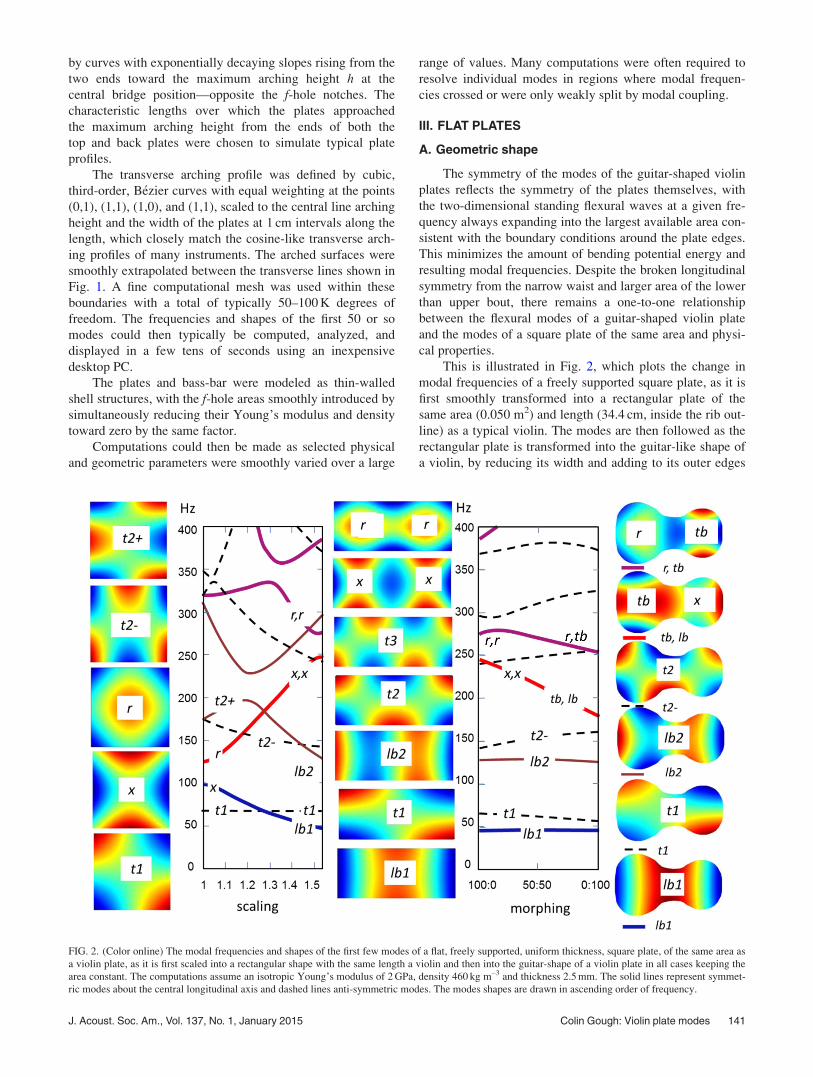
This is illustrated in Fig. 2, which plots the change in
modal frequencies of a freely supported square plate, as it is
first smoothly transformed into a rectangular plate of the
same area (0.050 m2) and length (34.4 cm, inside the rib out-
line) as a typical violin. The modes are then followed as the
rectangular plate is transformed into the guitar-like shape of
a violin, by reducing its width and adding to its outer edges
FIG. 2. (Color online) The modal frequencies and shapes of the first few modes of a flat, freely supported, uniform thickness, square plate, of the same area as
a violin plate, as it is first scaled into a rectangular shape with the same length a violin and then into the guitar-shape of a violin plate in all cases keeping the
area constant. The computations assume an isotropic Young’s modulus of 2 GPa, density 460 kg m–3 and thickness 2.5 mm. The solid lines represent symmet-
ric modes about the central longitudinal axis and dashed lines anti-symmetric modes. The modes shapes are drawn in ascending order of frequency.
J. Acoust. Soc. Am., Vol. 137, No. 1, January 2015 Colin Gough: Violin plate modes 141
the appropriately scaled left and right halves of the guitar-
shaped plate, in all cases maintaining a constant area.
Although the geometrical transformations strongly influ-
ence the modal shapes and frequencies, they leave the num-
ber of modes unchanged. Individual square plate modes can
then be followed as they are smoothly transformed into those
of the guitar-shaped violin plate. Because transverse symme-
try is preserved, the plate modes are either symmetric or
anti-symmetric with respect to the central axis. Only modes
sharing common symmetry elements can interact, so that the
frequencies of anti-symmetric and symmetric modes simply
cross when their frequencies coincide.
In contrast, modes sharing the same symmetry can inter-
act on changing the geometry. Their coupling leads to the
illustrated strong veering and splitting of the coupled mode
frequencies in the regions over which they would otherwise
have crossed. The coupled vibrations of a pair of interacting
modes then form a new pair of independent normal modes
describing their coupled vibrations. The veering and splitting
of the modes of the coupled vibrations of all the component
parts of the violin structure (plates, ribs, cavity modes, fin-
gerboard, neck, tailpiece, strings, etc.) are ubiquitous fea-
tures pervading almost every aspect of violin acoustics,
which can invariably be understood by standard coupled-
resonator models.
As illustrated in Fig. 2, the degeneracy of several of the
otherwise degenerate modes of the square plate is lifted by
the Poisson effect. This describes the induced contraction
across the width of a rectangular plate as it is extended along
its length, with the ratio of associated strains given by the
Poisson constant l. When a plate is bent along a given direc-
tion, the extension of the upper and contraction of the lower
surface along the length therefore induces extensions, con-
tractions and anti-clastic bending (i.e., in the opposite sense)
across the length. The ratio of induced to applied curvatures
is again given by l.
Fletcher and Rossing23 (Sec. 3.9) describe how the
Poisson effect results in a splitting in frequency of the other-
wise degenerate (1,0) and (0,1) bending modes of a square
plate. This results in the formation of an anti-clastic bendingx-mode and a higher-frequency synclastic (same sense) ringor r-mode, named after the shape of their associated nodal
lines. Very similar nodal line shapes are observed for modes
#2 and #5 of freely supported arched violin plates. It is there-
fore interesting to see how such modes are related on trans-
formation from the initially square- to guitar-shaped plates.
On transforming the square plate into an equal-area but
longer rectangular plate, the splitting of modes from the
Poisson effect (a typical value for l¼ 0.35 has been used in
all computations) is rapidly dwarfed by the much larger sep-
aration of the modes from the different length and width,
with bending frequencies along these directions inversely
proportional to their lengths squared. In contrast, the low fre-
quency t1 twisting mode is only weakly perturbed by the
change in geometry. The lower frequency x-mode is trans-
formed into a significantly lower frequency lb1 longitudinal
bending mode. In contrast, the square plate r ring mode is
transformed into a much higher frequency (x,x) mode—
(lower, upper) bout modes, with a pair of x-modes along the
length. Unsurprisingly, this mode is accompanied by a (r,r)
mode at a slightly higher frequency comprising a lengthwise
pair of ring modes, with the frequencies of the localized (x,x)
and (r,r) modes again split by the Poisson effect. The veering
and splitting of all the plotted modes can be understood in
terms of their symmetry and changing dimensions.
The subsequent transformation from rectangular to
guitar-shaped plate breaks the symmetry along the longitudi-
nal axis. Because the resulting modes involve an increase in
area of the lower bouts and a decrease in area of the upper
bouts, the perturbations of modal frequencies of modes span-
ning both bouts tend to compensate each other, as in the lb1
and lb2 longitudinal bending modes. However, the (x,x)
mode, with x modes in the lower and upper bouts, is strongly
perturbed as the width of the lower bout is increased—
sufficiently for a tb transverse bending wave to be preferred
in the lower bouts and a lb bending wave in the narrower
upper bout.
Note the tendency for localization of different standing
wave mode shapes in the lower and upper bouts, exemplified
by the (tb,x) and (r,tb) symmetry mode shapes, with local-
ized tb vibrations first appearing in the larger area lower
bout and at a higher frequency mode in the smaller area
upper bout. The localization of component standing waves
shapes in the lower bouts followed by the upper bout at
higher frequencies is a characteristic feature of all the higher
frequency plate modes. This also extends to the assembled
body shell, where the lower and upper bout localization of
particular vibrational modes occurs first in the more flexible
top plate and at higher frequencies in the less flexible back
plate.
IV. ARCHED AND ANISOTROPIC PLATES
A. Arching
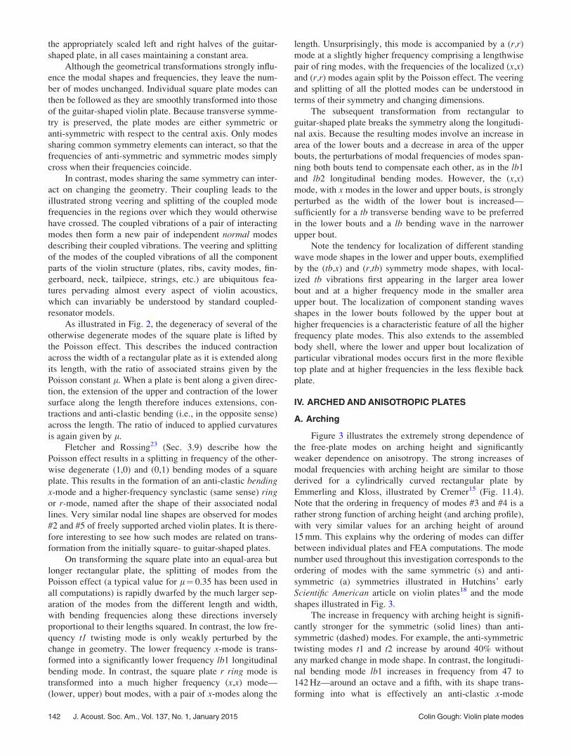
Figure 3 illustrates the extremely strong dependence of
the free-plate modes on arching height and significantly
weaker dependence on anisotropy. The strong increases of
modal frequencies with arching height are similar to those
derived for a cylindrically curved rectangular plate by
Emmerling and Kloss, illustrated by Cremer15 (Fig. 11.4).
Note that the ordering in frequency of modes #3 and #4 is a
rather strong function of arching height (and arching profile),
with very similar values for an arching height of around
15 mm. This explains why the ordering of modes can differ
between individual plates and FEA computations. The mode
number used throughout this investigation corresponds to the
ordering of modes with the same symmetric (s) and anti-
symmetric (a) symmetries illustrated in Hutchins’ early
Scientific American article on violin plates18 and the mode
shapes illustrated in Fig. 3.
The increase in frequency with arching height is signifi-
cantly stronger for the symmetric (solid lines) than anti-
symmetric (dashed) modes. For example, the anti-symmetric
twisting modes t1 and t2 increase by around 40% without
any marked change in mode shape. In contrast, the longitudi-
nal bending mode lb1 increases in frequency from 47 to
142 Hz—around an octave and a fifth, with its shape trans-
forming into what is effectively an anti-clastic x-mode
142 J. Acoust. Soc. Am., Vol. 137, No. 1, January 2015 Colin Gough: Violin plate modes
localized within the lower bout. Similarly, the second longi-
tudinal bending mode of the flat plate increases in frequency
from 120 to over 200 Hz—almost an octave—to form an
equivalent x-mode in the upper bout. Likewise, the (tb, x)
mode transforms into the equivalent of the #5 mode of a
square plate.
B. Elastic anisotropy
The influence of anisotropy has been computed by mod-
eling the plates as a composite structure of alternating, equal
density, narrow strips (typically 2.5 or 5 mm wide) of high
and low Young’s modulus material aligned along the
length.24 This simulates the orthotropic elastic properties
produced by the alternating early and late summer growths
of wood, but on a somewhat larger scale. This circumvents
the absence, in the available and otherwise extremely power-
ful and user-friendly commercial COMSOL shell structure
software, of the facility to model orthotropic materials. The
Young’s moduli of the alternating strips are specified as
aEgm and Egm/a corresponding to an anisotropy ratio A’ (a2þ 1)2/4a2, where Egm is the geometric mean of the
along- and cross-grain Young’s modulus. Cremer15 Sec.
11.2 has previously shown that the number of flexural plate
modes below a given high-frequency is largely determined
by the geometric mean modulus. The isotropic-plate model
extends the model to low frequencies, but with an arching
dependent Young’s modulus.
Modal frequencies computed with the above model for
anisotropy agree to within a few percent with those com-
puted using COMSOL orthotropic Mindlin plate computa-
tions for simple, edge-pinned, structures, using orthotropic
elastic properties. Although the grain structure is signifi-
cantly larger than that of the spruce and maple used for the
top and back plates, it is much smaller than flexural wave-
lengths of interest. Well-defined mode shapes can therefore
by identified up to and beyond 4 kHz, with flexural wave-
lengths still spanning �10 alternating strips.
Figure 3 shows a decrease of mode #2 and #5 frequen-
cies of around 15% as the anisotropy ratio is increased from
unity to 25 (spruce is typically around 20 and maple around
4–6 (e.g., Molin et al.20). However, modes #1, #3, and #4
are scarcely affected. The influence of anisotropy on the #2
and #5 modes, which are commonly believed to be the most
important free plate modes determining the acoustical prop-
erties of the assembled violin, is therefore significantly less
than that of the arching.
In recent years, measurements have shown that the aver-
age #5/#2 frequency ratio for the top plates of classic Italian
and high quality modern violins is typically close to 2.3,25,26
significantly larger than the value of 2 advocated by
Hutchins for “octave tuning.”27 Remarkably, the computed
mode #5 to #2 frequency ratio changes by less than 4% over
the whole anisotropy range, from an initial value of 2.14 for
an isotropic material, decreasing initially to a minimum of
2.10 for an anisotropy ratio in the range 2–3, rising back to
FIG. 3. (Color online) The dependence of mode frequencies and shapes on arching height and elastic anisotropy for a guitar-shaped with the same properties
listed in Fig. 2.
J. Acoust. Soc. Am., Vol. 137, No. 1, January 2015 Colin Gough: Violin plate modes 143
the isotropic value for an anisotropy of around 16 and con-
tinuing to rise weakly to 2.19 for an anisotropy ratio of 25.
The relative insensitivity of this ratio to elastic anisotropy is
consistent with earlier FEA computations by Molin et al.20
(Table I) giving frequency ratios of 2.36 and 2.24 for other-
wise identical, freely supported, uniformly thick (3.5 mm),
maple (anisotropy 6.1) and spruce (anisotropy 16.4) arched
plates.
The relative insensitivity of the above ratio to such a
wide range of anisotropies implies that both #2 and #5
modes are affected in much the same way by the along- and
cross-grain Young’s moduli. In addition, the robustness of
the modes to large changes in anisotropy supports the pro-
posed uniform isotropic arched plate model used to simulate
the generic properties of real violin plates both on and off
the instrument.
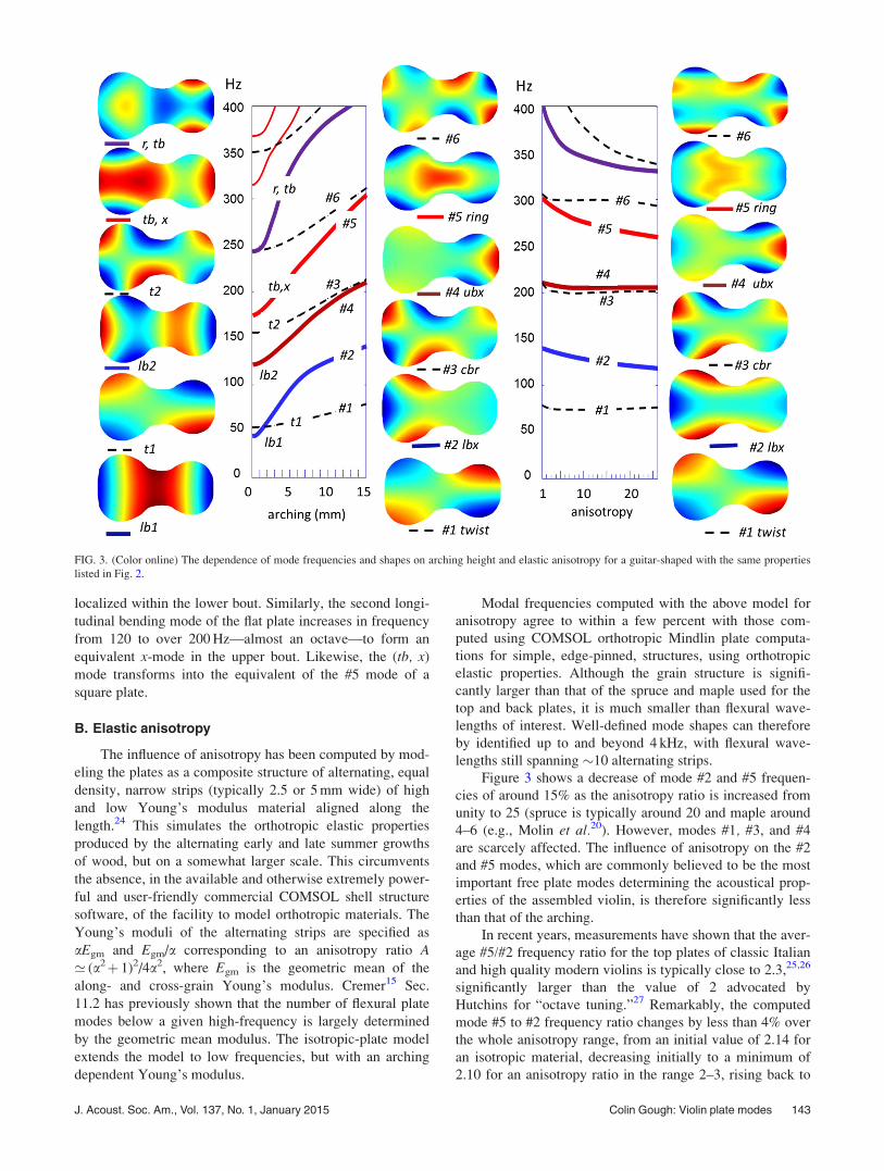
As a test of the validity of the proposed model, Table I
compares the frequencies derived from the generic isotropic
plate model with those derived from previously published
FEA calculations and measurements for orthotropic violin
plates. Such comparisons inevitably involve plates with dif-
ferent arching profiles and thickness graduations, so exact
frequency matching and ordering of modes would never be
expected. Where possible, comparisons have been made for
top plates without f-holes and bass-bar, though this is clearly
not possible for classic Italian violins. Nevertheless the over-
all agreement with earlier measurements and computations,
all sharing very similar mode shapes, is remarkably good,
especially in terms of the #5/#2 frequency ratios, with
absolute values which can easily be scaled by adjusting the
isotropic averaged Young’s modulus to density ratio.
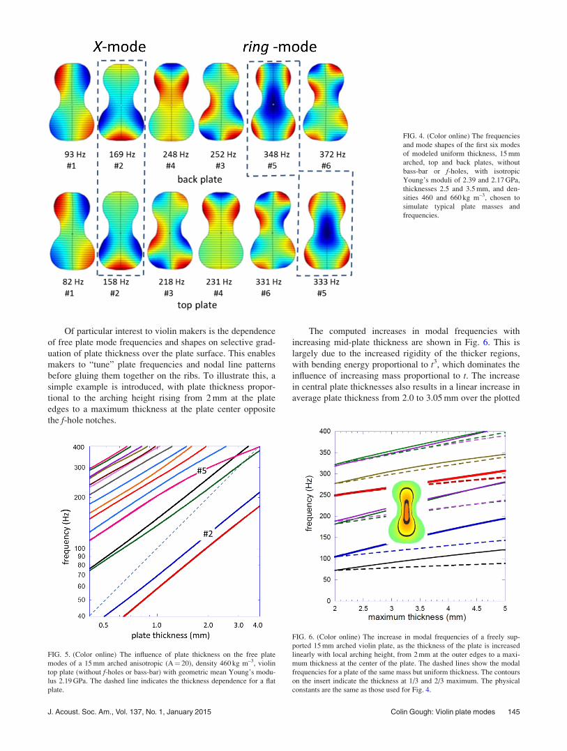
As an example, Fig. 4 illustrates the first six, freely sup-
ported, top and back plate modes (without f-holes or bass-
bar) computed with isotropic Young’s moduli chosen to
reproduce typical freely supported plate frequencies. Both
plates have a mid-plate arching height of 15 mm, with
averaged front and back plate Young’s moduli of 2.39 and
2.17 GPa, densities of 460 and 660 kg m–3, and thicknesses
2.5 and 3.6 mm, with masses 57 and 118 g. Note the sensitiv-
ity of the top and back plate mode frequencies and ordering
to the relatively small differences in the front and back plate
longitudinal arching profiles. These are the plates used in a
preliminary conference account of the development of the
proposed model of the violin body shell,14 to be described
along with its acoustically radiating properties in a later
paper.
C. Plate thickness
Figure 5 shows the computed frequencies of the first 20
modes of a 15 mm arched, strongly anisotropic, violin plate,
for a wide range of plate thicknesses, plotted on logarithmic
scales. The slopes are considerably smaller than the flat-
plate value of unity (frequency proportional to thickness).
This is because of the arching-induced longitudinal strains,
which dominate the bending energies and frequencies of the
lowest-frequency flexural modes. The influence of the arch-
ing is particularly strong for the #5 plate mode, with a 10%
increase in thickness of a 2.5 mm plate only changing its fre-
quency by around 4%, though a larger change of around 8%
is derived for the #2 mode. The #5/#2 frequency ratio is
therefore a relatively strong function of both arching height
and plate thickness. For the 15 mm arched plate, the com-
puted ratio falls from 2.97 for 1 mm, 2.46 for 2 mm, 2.11 for
3 mm, and 1.86 for 4 mm thick plates. The average of 2.3 for
fine Italian violins25 would therefore be reproduced by a
uniform spruce plate thickness slightly less than 2.5 mm,
consistent with the thickness of real plates. This is also in
qualitative agreement with the dependence illustrated in ear-
lier FEA computations by Molin et al.20 (Table II) giving a
decrease in frequency ratio from 2.65 to 2.41, on increasing
the thickness of a 16 mm arched spruce plate from 2.5 to
3.5 mm.
TABLE I. Computed freely supported frequencies for the back and top plates illustrated in Fig. 4, and measurements and FEA values from earlier publications.
The Molin et al. (Ref. 20) frequencies were for 13.5 mm mid-plane arching height, uniform 3.5 mm thickness, orthotropic, maple, and spruce plates with ani-
sotropy ratios of 5.02 and 16.5 rather than graduated thickness plates. The Cremonese average frequencies and their scatter are for nine classic Italian violins
including four Stradivari and one Guarneri violins (Ref. 25).
Mode #1 (a) #2 (s) #3 (a) #4 (s) #5 (s) #5/#2
Back-maple
Isotropic model (FEA) 93 169 248 252 348 2.07
Hutchins (meas.) (Ref. 18) 116 167 222 230 349 2.08
Roberts (FEA) (Ref. 4) 127 186 312 294 362 2.17
Rodgers (FEA) (Ref. 19) 113 148 250 229 351 2.37
Molin et al. (meas) (Ref. 20) 125 213 373 352 467 2.19
Molin et al. (FEA) (Ref. 20) 130 209 367 342 493 2.36
Bretos et al. (FEA) (Ref. 5) 107 176 284 231 353 2.00
Top-spruce
Isotropic model (FEA) 82 158 218 231 333 2.12
Hutchins (meas.) (Ref. 18) 80 147 222 349 2.37
Roberts (FEA) (Ref. 4) 80 146 241 251 295 2.02
Molin et al. (meas) (Ref. 20) 106 196 343 339 471 2.40
Molin et al. (FEA) (Ref. 20) 105 200 317 332 448 2.24
Bretos et al. (FEA) (Ref. 5) 92 168 346 2.06
Cremonese average (Ref. 25) 134 6 17 314 6 30 2.34 6�0.2
144 J. Acoust. Soc. Am., Vol. 137, No. 1, January 2015 Colin Gough: Violin plate modes
Of particular interest to violin makers is the dependence
of free plate mode frequencies and shapes on selective grad-
uation of plate thickness over the plate surface. This enables
makers to “tune” plate frequencies and nodal line patterns
before gluing them together on the ribs. To illustrate this, a
simple example is introduced, with plate thickness propor-
tional to the arching height rising from 2 mm at the plate
edges to a maximum thickness at the plate center opposite
the f-hole notches.
The computed increases in modal frequencies with
increasing mid-plate thickness are shown in Fig. 6. This is
largely due to the increased rigidity of the thicker regions,
with bending energy proportional to t3, which dominates the
influence of increasing mass proportional to t. The increase
in central plate thicknesses also results in a linear increase in
average plate thickness from 2.0 to 3.05 mm over the plotted
FIG. 5. (Color online) The influence of plate thickness on the free plate
modes of a 15 mm arched anisotropic (A¼ 20), density 460 kg m–3, violin
top plate (without f-holes or bass-bar) with geometric mean Young’s modu-
lus 2.19 GPa. The dashed line indicates the thickness dependence for a flat
plate.
FIG. 4. (Color online) The frequencies
and mode shapes of the first six modes
of modeled uniform thickness, 15 mm
arched, top and back plates, without
bass-bar or f-holes, with isotropic
Young’s moduli of 2.39 and 2.17 GPa,
thicknesses 2.5 and 3.5 mm, and den-
sities 460 and 660 kg m–3, chosen to
simulate typical plate masses and
frequencies.
FIG. 6. (Color online) The increase in modal frequencies of a freely sup-
ported 15 mm arched violin plate, as the thickness of the plate is increased
linearly with local arching height, from 2 mm at the outer edges to a maxi-
mum thickness at the center of the plate. The dashed lines show the modal
frequencies for a plate of the same mass but uniform thickness. The contours
on the insert indicate the thickness at 1/3 and 2/3 maximum. The physical
constants are the same as those used for Fig. 4.
J. Acoust. Soc. Am., Vol. 137, No. 1, January 2015 Colin Gough: Violin plate modes 145
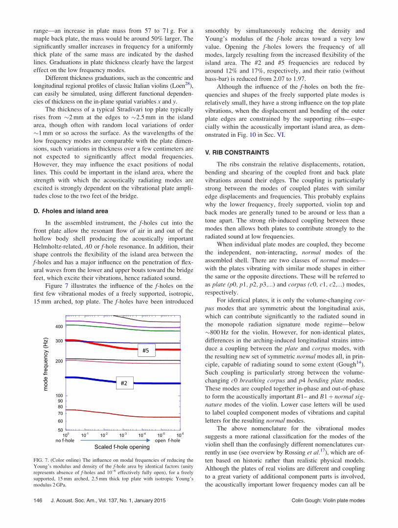
range—an increase in plate mass from 57 to 71 g. For a
maple back plate, the mass would be around 50% larger. The
significantly smaller increases in frequency for a uniformly
thick plate of the same mass are indicated by the dashed
lines. Graduations in plate thickness clearly have the largest
effect on the low frequency modes.
Different thickness graduations, such as the concentric and
longitudinal regional profiles of classic Italian violins (Loen28),
can easily be simulated, using different functional dependen-
cies of thickness on the in-plane spatial variables x and y.
The thickness of a typical Stradivari top plate typically
rises from �2 mm at the edges to �2.5 mm in the island
area, though often with random local variations of order
�1 mm or so across the surface. As the wavelengths of the
low frequency modes are comparable with the plate dimen-
sions, such variations in thickness over a few centimeters are
not expected to significantly affect modal frequencies.
However, they may influence the exact positions of nodal
lines. This could be important in the island area, where the
strength with which the acoustically radiating modes are
excited is strongly dependent on the vibrational plate ampli-
tudes close to the two feet of the bridge.
D. f-holes and island area
In the assembled instrument, the f-holes cut into the
front plate allow the resonant flow of air in and out of the
hollow body shell producing the acoustically important
Helmholtz-related, A0 or f-hole resonance. In addition, their
shape controls the flexibility of the island area between the
f-holes and has a major influence on the penetration of flex-
ural waves from the lower and upper bouts toward the bridge
feet, which excite their vibrations, hence radiated sound.
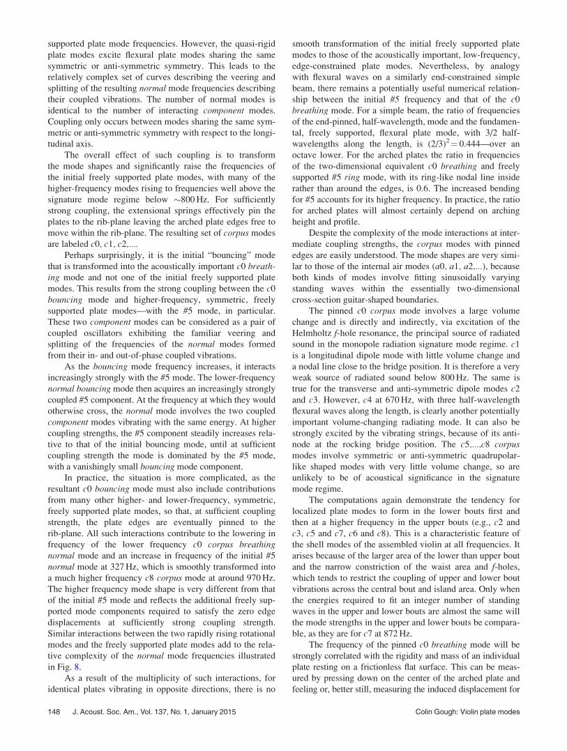
Figure 7 illustrates the influence of the f-holes on the
first few vibrational modes of a freely supported, isotropic,
15 mm arched, top plate. The f-holes have been introduced
smoothly by simultaneously reducing the density and
Young’s modulus of the f-hole areas toward a very low
value. Opening the f-holes lowers the frequency of all
modes, largely resulting from the increased flexibility of the
island area. The #2 and #5 frequencies are reduced by
around 12% and 17%, respectively, and their ratio (without
bass-bar) is reduced from 2.07 to 1.97.
Although the influence of the f-holes on both the fre-
quencies and shapes of the freely supported plate modes is
relatively small, they have a strong influence on the top plate
vibrations, when the displacement and bending of the outer
plate edges are constrained by the supporting ribs—espe-
cially within the acoustically important island area, as dem-
onstrated in Fig. 10 in Sec. VI.
V. RIB CONSTRAINTS
The ribs constrain the relative displacements, rotation,
bending and shearing of the coupled front and back plate
vibrations around their edges. The coupling is particularly
strong between the modes of coupled plates with similar
edge displacements and frequencies. This probably explains
why the lower frequency, freely supported, violin top and
back modes are generally tuned to be around or less than a
tone apart. The strong rib-induced coupling between these
modes then allows both plates to contribute strongly to the
radiated sound at low frequencies.
When individual plate modes are coupled, they become
the independent, non-interacting, normal modes of the
assembled shell. There are two classes of normal modes—
with the plates vibrating with similar mode shapes in either
the same or the opposite directions. These will be referred to
as plate (p0, p1, p2, p3,...) and corpus (c0, c1, c2,...) modes,
respectively.
For identical plates, it is only the volume-changing cor-pus modes that are symmetric about the longitudinal axis,
which can contribute significantly to the radiated sound in
the monopole radiation signature mode regime—below
�800 Hz for the violin. However, for non-identical plates,
differences in the arching-induced longitudinal strains intro-
duce a coupling between the plate and corpus modes, with
the resulting new set of symmetric normal modes all, in prin-
ciple, capable of radiating sound to some extent (Gough14).
Such coupling is particularly strong between the volume-
changing c0 breathing corpus and p4 bending plate modes.
These modes are coupled together in-phase and out-of-phase
to form the acoustically important B1– and B1þ normal sig-nature modes of the violin. Lower case letters will be used
to label coupled component modes of vibrations and capital
letters for the resulting normal modes.
The above nomenclature for the vibrational modes
suggests a more rational classification for the modes of the
violin shell than the confusingly different nomenclatures cur-
rently in use (see overview by Rossing et al.17), which are of-
ten based on historic rather than realistic physical models.
Although the plates of real violins are different and coupling
to a great variety of additional component parts is involved,
the acoustically important lower frequency modes can all be
FIG. 7. (Color online) The influence on modal frequencies of reducing the
Young’s modulus and density of the f-hole area by identical factors (unity
represents absence of f-holes and 10–6 effectively fully open), for a freely
supported, 15 mm arched, 2.5 mm thick top plate with isotropic Young’s
modulus 2 GPa.
146 J. Acoust. Soc. Am., Vol. 137, No. 1, January 2015 Colin Gough: Violin plate modes
described and understood using the above classification of
modes—as described in a planned subsequent paper.
A. Extensional spring constraints
The influence is now considered of extensional springs
constraining edge displacements and torsional springs con-
straining plate bending and rotation around the plate edges,
as an introduction to the influence of rib coupling on the top
and back plate vibrations of real instruments.
Consider first the frequencies and mode shapes of identi-
cal plates vibrating in opposite directions—the platemodes—constrained by massless extensional springs distrib-
uted uniformly around their edges. By symmetry, such modes
are equivalent to those of individual plates constrained
around their edges by springs of half the length.
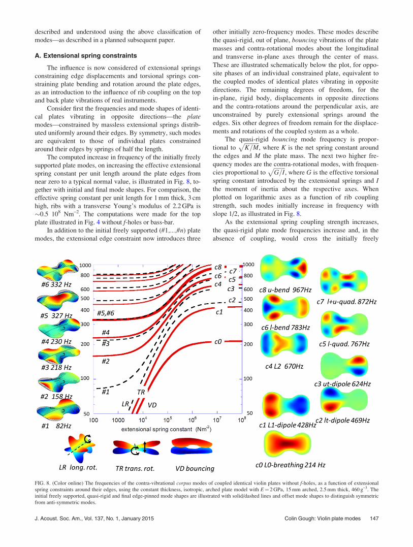
The computed increase in frequency of the initially freely
supported plate modes, on increasing the effective extensional
spring constant per unit length around the plate edges from
near zero to a typical normal value, is illustrated in Fig. 8, to-
gether with initial and final mode shapes. For comparison, the
effective spring constant per unit length for 1 mm thick, 3 cm
high, ribs with a transverse Young’s modulus of 2.2 GPa is
�0.5 108 Nm–2. The computations were made for the top
plate illustrated in Fig. 4 without f-holes or bass-bar.
In addition to the initial freely supported (#1,...,#n) plate
modes, the extensional edge constraint now introduces three
other initially zero-frequency modes. These modes describe
the quasi-rigid, out of plane, bouncing vibrations of the plate
masses and contra-rotational modes about the longitudinal
and transverse in-plane axes through the center of mass.
These are illustrated schematically below the plot, for oppo-
site phases of an individual constrained plate, equivalent to
the coupled modes of identical plates vibrating in opposite
directions. The remaining degrees of freedom, for the
in-plane, rigid body, displacements in opposite directions
and the contra-rotations around the perpendicular axis, are
unconstrained by purely extensional springs around the
edges. Six other degrees of freedom remain for the displace-
ments and rotations of the coupled system as a whole.
The quasi-rigid bouncing mode frequency is propor-
tional toffiffiffiffiffiffiffiffiffiffiK=M
p, where K is the net spring constant around
the edges and M the plate mass. The next two higher fre-
quency modes are the contra-rotational modes, with frequen-
cies proportional toffiffiffiffiffiffiffiffiG=I
p, where G is the effective torsional
spring constant introduced by the extensional springs and Ithe moment of inertia about the respective axes. When
plotted on logarithmic axes as a function of rib coupling
strength, such modes initially increase in frequency with
slope 1/2, as illustrated in Fig. 8.
As the extensional spring coupling strength increases,
the quasi-rigid plate mode frequencies increase and, in the
absence of coupling, would cross the initially freely
FIG. 8. (Color online) The frequencies of the contra-vibrational corpus modes of coupled identical violin plates without f-holes, as a function of extensional
spring constraints around their edges, using the constant thickness, isotropic, arched plate model with E¼ 2 GPa, 15 mm arched, 2.5 mm thick, 460 g–3. The
initial freely supported, quasi-rigid and final edge-pinned mode shapes are illustrated with solid/dashed lines and offset mode shapes to distinguish symmetric
from anti-symmetric modes.
J. Acoust. Soc. Am., Vol. 137, No. 1, January 2015 Colin Gough: Violin plate modes 147
supported plate mode frequencies. However, the quasi-rigid
plate modes excite flexural plate modes sharing the same
symmetric or anti-symmetric symmetry. This leads to the
relatively complex set of curves describing the veering and
splitting of the resulting normal mode frequencies describing
their coupled vibrations. The number of normal modes is
identical to the number of interacting component modes.
Coupling only occurs between modes sharing the same sym-
metric or anti-symmetric symmetry with respect to the longi-
tudinal axis.
The overall effect of such coupling is to transform
the mode shapes and significantly raise the frequencies of
the initial freely supported plate modes, with many of the
higher-frequency modes rising to frequencies well above the
signature mode regime below �800 Hz. For sufficiently
strong coupling, the extensional springs effectively pin the
plates to the rib-plane leaving the arched plate edges free to
move within the rib-plane. The resulting set of corpus modes
are labeled c0, c1, c2,....Perhaps surprisingly, it is the initial “bouncing” mode
that is transformed into the acoustically important c0 breath-ing mode and not one of the initial freely supported plate
modes. This results from the strong coupling between the c0
bouncing mode and higher-frequency, symmetric, freely
supported plate modes—with the #5 mode, in particular.
These two component modes can be considered as a pair of
coupled oscillators exhibiting the familiar veering and
splitting of the frequencies of the normal modes formed
from their in- and out-of-phase coupled vibrations.
As the bouncing mode frequency increases, it interacts
increasingly strongly with the #5 mode. The lower-frequency
normal bouncing mode then acquires an increasingly strongly
coupled #5 component. At the frequency at which they would
otherwise cross, the normal mode involves the two coupled
component modes vibrating with the same energy. At higher
coupling strengths, the #5 component steadily increases rela-
tive to that of the initial bouncing mode, until at sufficient
coupling strength the mode is dominated by the #5 mode,
with a vanishingly small bouncing mode component.
In practice, the situation is more complicated, as the
resultant c0 bouncing mode must also include contributions
from many other higher- and lower-frequency, symmetric,
freely supported plate modes, so that, at sufficient coupling
strength, the plate edges are eventually pinned to the
rib-plane. All such interactions contribute to the lowering in
frequency of the lower frequency c0 corpus breathingnormal mode and an increase in frequency of the initial #5
normal mode at 327 Hz, which is smoothly transformed into
a much higher frequency c8 corpus mode at around 970 Hz.
The higher frequency mode shape is very different from that
of the initial #5 mode and reflects the additional freely sup-
ported mode components required to satisfy the zero edge
displacements at sufficiently strong coupling strength.
Similar interactions between the two rapidly rising rotational
modes and the freely supported plate modes add to the rela-
tive complexity of the normal mode frequencies illustrated
in Fig. 8.
As a result of the multiplicity of such interactions, for
identical plates vibrating in opposite directions, there is no
smooth transformation of the initial freely supported plate
modes to those of the acoustically important, low-frequency,
edge-constrained plate modes. Nevertheless, by analogy
with flexural waves on a similarly end-constrained simple
beam, there remains a potentially useful numerical relation-
ship between the initial #5 frequency and that of the c0
breathing mode. For a simple beam, the ratio of frequencies
of the end-pinned, half-wavelength, mode and the fundamen-
tal, freely supported, flexural plate mode, with 3/2 half-
wavelengths along the length, is (2/3)2¼ 0.444—over an
octave lower. For the arched plates the ratio in frequencies
of the two-dimensional equivalent c0 breathing and freely
supported #5 ring mode, with its ring-like nodal line inside
rather than around the edges, is 0.6. The increased bending
for #5 accounts for its higher frequency. In practice, the ratio
for arched plates will almost certainly depend on arching
height and profile.
Despite the complexity of the mode interactions at inter-
mediate coupling strengths, the corpus modes with pinned
edges are easily understood. The mode shapes are very simi-
lar to those of the internal air modes (a0, a1, a2,...), because
both kinds of modes involve fitting sinusoidally varying
standing waves within the essentially two-dimensional
cross-section guitar-shaped boundaries.
The pinned c0 corpus mode involves a large volume
change and is directly and indirectly, via excitation of the
Helmholtz f-hole resonance, the principal source of radiated
sound in the monopole radiation signature mode regime. c1
is a longitudinal dipole mode with little volume change and
a nodal line close to the bridge position. It is therefore a very
weak source of radiated sound below 800 Hz. The same is
true for the transverse and anti-symmetric dipole modes c2
and c3. However, c4 at 670 Hz, with three half-wavelength
flexural waves along the length, is clearly another potentially
important volume-changing radiating mode. It can also be
strongly excited by the vibrating strings, because of its anti-
node at the rocking bridge position. The c5,...,c8 corpusmodes involve symmetric or anti-symmetric quadrupolar-
like shaped modes with very little volume change, so are
unlikely to be of acoustical significance in the signature
mode regime.
The computations again demonstrate the tendency for
localized plate modes to form in the lower bouts first and
then at a higher frequency in the upper bouts (e.g., c2 and
c3, c5 and c7, c6 and c8). This is a characteristic feature of
the shell modes of the assembled violin at all frequencies. It
arises because of the larger area of the lower than upper bout
and the narrow constriction of the waist area and f-holes,
which tends to restrict the coupling of upper and lower bout
vibrations across the central bout and island area. Only when
the energies required to fit an integer number of standing
waves in the upper and lower bouts are almost the same will
the mode strengths in the upper and lower bouts be compara-
ble, as they are for c7 at 872 Hz.
The frequency of the pinned c0 breathing mode will be
strongly correlated with the rigidity and mass of an individual
plate resting on a frictionless flat surface. This can be meas-
ured by pressing down on the center of the arched plate and
feeling or, better still, measuring the induced displacement for
148 J. Acoust. Soc. Am., Vol. 137, No. 1, January 2015 Colin Gough: Violin plate modes
a given downward force. For the modeled arched top plate of
mass m¼ 57 g, the computed rigidity spring constant
K¼ 2.12 105 Nm–1, which would give the computed pinnedc0 mode frequency of
ffiffiffiffiffiffiffiffiffiffiffiffiK=m�
p=2p ¼ 216 Hz, with effective
plate mass m*¼ 0.20 m, compared with m*¼ 0.25 m for a
flat, pinned, isotropic, rectangular plate.
In practice, the rib strength (plus that of the corner and
end blocks) is never sufficiently strong to completely inhibit
the relative edge displacements of the top and back all the
way around their edges, though for the violin this is a very
good approximation, but perhaps less so for the cello with
much higher, yet still thin, ribs and heavier plate masses.
B. Rotational constraints
For plate modes with identical plates vibrating in the
same direction, extensional springs have no influence on the
coupled, initially freely supported, plate modes. However,
the bending of the ribs also constrains the rotation of the
plate edges parallel to their edges, which raises the fre-
quency of both the corpus and plate modes. This can be
modeled by a uniformly distributed array of torsional springs
around the plate edges.
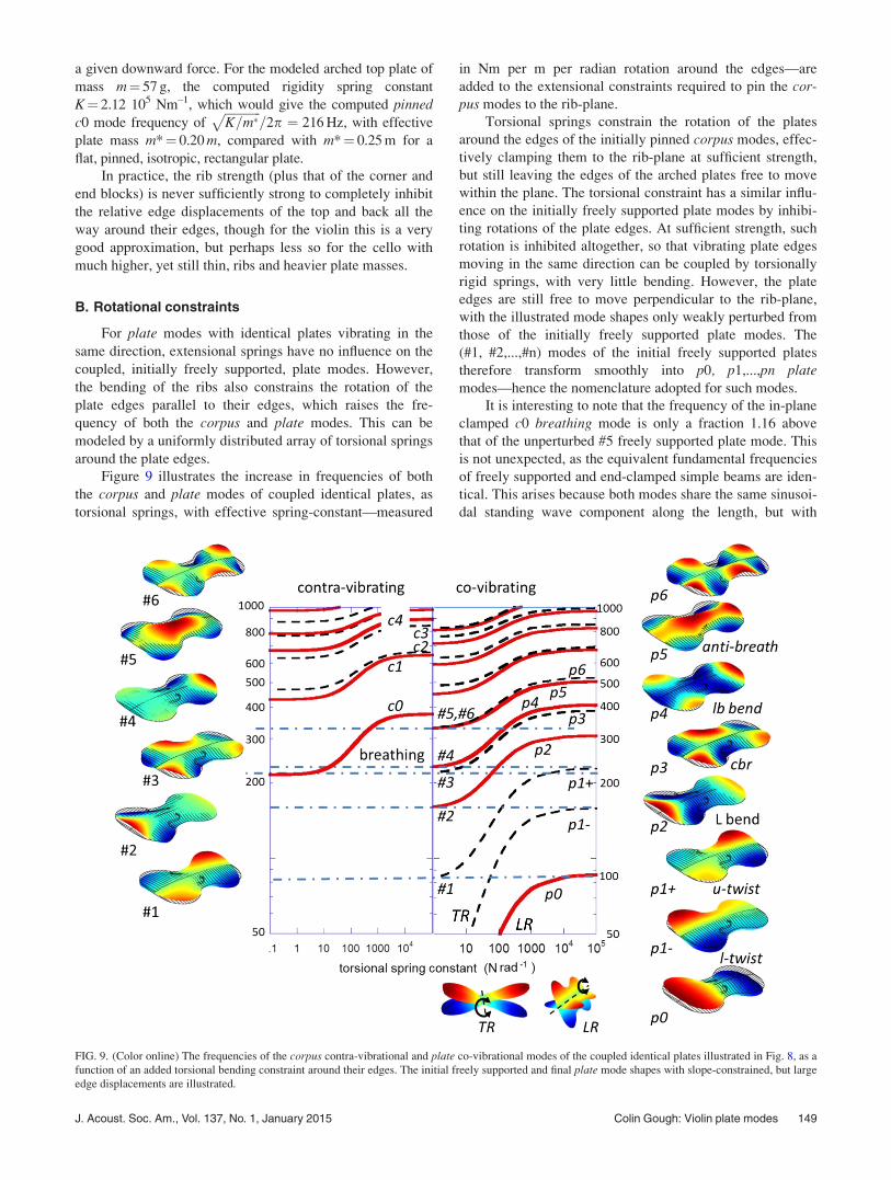
Figure 9 illustrates the increase in frequencies of both
the corpus and plate modes of coupled identical plates, as
torsional springs, with effective spring-constant—measured
in Nm per m per radian rotation around the edges—are
added to the extensional constraints required to pin the cor-pus modes to the rib-plane.
Torsional springs constrain the rotation of the plates
around the edges of the initially pinned corpus modes, effec-
tively clamping them to the rib-plane at sufficient strength,
but still leaving the edges of the arched plates free to move
within the plane. The torsional constraint has a similar influ-
ence on the initially freely supported plate modes by inhibi-
ting rotations of the plate edges. At sufficient strength, such
rotation is inhibited altogether, so that vibrating plate edges
moving in the same direction can be coupled by torsionally
rigid springs, with very little bending. However, the plate
edges are still free to move perpendicular to the rib-plane,
with the illustrated mode shapes only weakly perturbed from
those of the initially freely supported plate modes. The
(#1, #2,...,#n) modes of the initial freely supported plates
therefore transform smoothly into p0, p1,...,pn platemodes—hence the nomenclature adopted for such modes.
It is interesting to note that the frequency of the in-plane
clamped c0 breathing mode is only a fraction 1.16 above
that of the unperturbed #5 freely supported plate mode. This
is not unexpected, as the equivalent fundamental frequencies
of freely supported and end-clamped simple beams are iden-
tical. This arises because both modes share the same sinusoi-
dal standing wave component along the length, but with
FIG. 9. (Color online) The frequencies of the corpus contra-vibrational and plate co-vibrational modes of the coupled identical plates illustrated in Fig. 8, as a
function of an added torsional bending constraint around their edges. The initial freely supported and final plate mode shapes with slope-constrained, but large
edge displacements are illustrated.
J. Acoust. Soc. Am., Vol. 137, No. 1, January 2015 Colin Gough: Violin plate modes 149
exponentially decaying, near-field, solutions of opposite sign
at both ends, to satisfy the free�free and clamped boundary
conditions.
One would anticipate a similar relationship between the
fundamental freely supported and clamped modes of a two-
dimensional plate, though the ratio will almost certainly
depend on arching profiles and heights, which will differ
significantly between makers of different periods and work-
shops. In practice, the bending rigidity of real ribs (plus
corner and end blocks) results in plate modes intermediate
between being pinned and clamped around their edges, so
the ratio of #5 to the c0 breathing mode of identical plates
might, in practice, be even closer to unity.
The non-volume-changing plate modes of coupled
identical plates will be poor radiators in the signature mode
regime. Nevertheless, the p2 and p4 modes are important,
because when full rib-coupling is involved these modes are
coupled together to form the longitudinal anti-clastic bend-ing plate mode of the assembled shell. Any difference in the
coupled arched plates then results in a coupling between
the bending plate and breathing corpus modes to form the
important B1– and B1þ strongly radiating signature modes
of the violin.14 The p3 cbr plate mode becomes the CBR(c)entre (b)out (r)otation or (r)homboidal displacementmode of the body shell, which can sometimes contribute sig-
nificantly to the radiated sound via its coupling to the c0
breathing mode. The twisting and other higher frequency
modes are of little acoustic significance but will appear as
resonances in admittance measurements.
The boundary constraints around the plate edges have
their largest influence on the lower frequency corpus and
plate modes. At higher frequencies their influence is consid-
erably smaller, as the potential energy is increasingly deter-
mined by bending within the whole area of the plates rather
than around their edges.
C. In-plane constraints
Because the low frequency modes of arched plates
involve significant in-plane displacements of the plate edges
arising from the longitudinal strains induced by flexural
waves on the arched surfaces, clamping the plates to the
plate outline rather than allowing them to move freely within
the plane results in a further increase in frequency. For
example, the pinned c0 corpus mode frequency is 215 Hz;
when clamped to the rib-plane, this rises to 375 Hz increas-
ing to 1055 Hz, when rigidly clamped to the rib outline. In
practice, large in-plane edge constraints are already provided
by the longitudinal strains parallel to the plate edges within
the arched plates themselves. These are likely to be stronger
than those induced around the rib garland, but certainly not
sufficient to clamp the plates to the plate outline.
D. Non-identical plates
Although the above sections have focused on identical
plates, the vibrational modes of non-identical top and back
plate modes will be very similar. Consider, for example, the
corpus c0 breathing mode with identical top and back plate
frequencies, but different masses. Because the freely
supported coupled plates have to conserve momentum per-
pendicular to the plates, the frequencies and mode shapes of
the pinned corpus modes will be unchanged, but with plate
velocities inversely proportional to their masses to conserve
perpendicular momentum. Similarly, for bending constraints,
the vibrational amplitudes will be inversely proportional to
their flexural rigidities. The frequencies of the assembled
shell modes will therefore be an appropriately weighted
average of their individual boundary-constrained plate
frequencies.
In addition, as described above, differences in arching
heights and profiles and other physical properties result in
differential top and back plate longitudinal strains. This
introduces a coupling between the breathing and bendingmodes determining the radiating strengths of the dominant
B1– and B1þ signature modes of the violin.14
VI. SOUNDPOST
The soundpost introduces an additional localized bound-
ary constraint inhibiting relative plate displacements and
bending across its ends. To satisfy the boundary conditions,
an additional localized, near-field, non-propagating, second-
order Hankel-function29 solution to the bending wave equa-
tions has to be included to describe the top and back plate
vibrations. This decays at large distances as e–2pr/k/r1/2,
where k is the wavelength of propagating flexural waves at a
given frequency. At low frequencies, the soundpost has a
profound influence on mode shapes in the island area
between the f-holes extending well into the upper and lower
bouts, while at high frequencies its influence is increasingly
localized around the soundpost position, with a weaker influ-
ence on the plate modes within the upper and lower bouts.
The decay of the mode shapes in the vicinity of the sound-
post is also strongly influenced by the close proximity of the
freely supported inner f-hole edges.
Although a well-fitted soundpost will clamp the two
plates together across its ends, if not exactly fitted, it may
contact the plates at only one or two points, providing a less
strong constraint on the bending of the plates across its ends.
By purposely moving one end of the soundpost and not the
other, a skilled luthier can therefore adjust the soundpost
coupling strength to optimize the sound, in addition to
adjustments of the soundpost position.
For plate modes, with top and back plates modes vibrat-
ing with similar amplitudes in the same sense (e.g., the p3
cbr and the p2 and p4 bending modes), a centrally placed
soundpost has little effect on mode shapes and frequencies,
other than via its bending. However, for corpus modes, with
coupled plates vibrating in opposite directions, the soundpost
can introduce large changes in mode shapes and frequencies.
In particular, the soundpost has a very large influence on the
volume-changing, c0 and c4 breathing monopole radiation
sources, both having anti-nodes close to the rocking bridge
position.
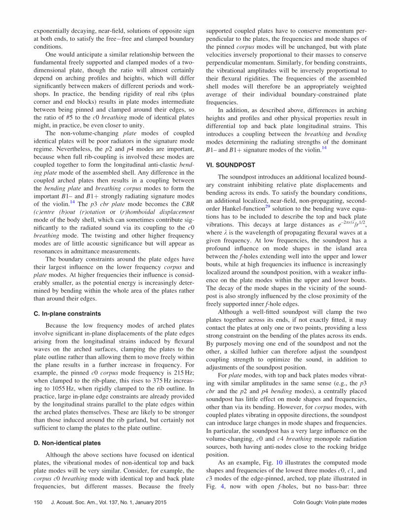
As an example, Fig. 10 illustrates the computed mode
shapes and frequencies of the lowest three modes c0, c1, and
c3 modes of the edge-pinned, arched, top plate illustrated in
Fig. 4, now with open f-holes, but no bass-bar: three
150 J. Acoust. Soc. Am., Vol. 137, No. 1, January 2015 Colin Gough: Violin plate modes
configurations are considered—without a soundpost, a cen-
trally placed soundpost and a soundpost offset toward the
treble side by 2 cm. The soundpost is assumed to be well-
fitted inhibiting both displacement and bending across its
contact area. The soundpost would have a similar influence
on the back plate modes, but without the concentration of
flexural wave displacements within the island area.
The soundpost effectively acts as a “gate” controlling
the coupling of flexural waves penetrating between the lower
and upper bouts through the island area. When centrally
placed, it localizes the initial c0 breathing mode into the
lower bout raising its frequency from 177 Hz to 376 Hz—
over an octave—and introduces an equivalent breathing
mode in the upper bout at 438 Hz. These modes can be con-
sidered, at least qualitatively, as the in- and out-of phase
combinations of the component c0 monopole and c1 dipole
plate modes before the soundpost was added. However,
many additional higher-order modes would also be required,
to describe the rapid changes in mode shape around the
soundpost.
On progressively moving the soundpost away from the
central symmetry line, the soundpost “gate” opens to allow
an increasing penetration of flexural waves through the
island area, on the opposite side to the soundpost. For an
offset of 2 cm, this results in an asymmetric breathing mode
at 307 Hz, which is still almost an octave above that of the
edge-pinned plate without a soundpost—177 Hz. This mode
can be qualitatively described as involving a combination of
the initial c0 monopole and c2 transverse dipole plate modes,
though many other higher frequency modes would again be
required to describe the actual mode shape. Although a
centrally placed soundpost has little effect on the initial c2
transverse dipole mode, the transverse offset inhibits the
penetration of the mode into the island area, with a signifi-
cant increase in frequency from 369 to 461 Hz, also inhibi-
ting its coupling to the asymmetrical rocking of the bridge.
The degree of asymmetry across the central island area
on which the bridge stands is well known to determine the
efficiency with which energy from the bowed string can be
transferred via the asymmetrically rocking bridge to the
strongly radiating breathing modes of the assembled instru-
ment (Schelleng30). The sensitivity of this asymmetry to the
transverse offset of the soundpost is therefore an important
factor in determining the intensity of radiated sound in the
monopole signature mode regime. Moving the soundpost
toward the upper bout allows a greater penetration of the
lower bout vibrations into the island area, with an associated
lowering of the c0 breathing mode frequency, hence chang-
ing the timbre of sound at low frequencies - with changes in
the opposite sense on moving the soundpost toward the
lower bout.
The computed frequencies and mode shapes are very
similar to those observed in three-dimensional holographic
investigations of the fully assembled violin by Runnermalm
et al.16 and obtained from experimental modal analysis
measurements by Bissinger13 and Stoppani.12
VII. BASS-BAR
The offset bass-bar acts as a localized strengthening
beam along the island area under the bass side foot of the
bridge extending into the lower and upper bouts. Because
the bass-bar inhibits bending along its length, it can have
two quite distinct effects. At low frequency, its bending ri-
gidity tends to enhance the coupling between the lower and
upper bout vibrations. This occurs because vibrations in both
bouts tending to “lock on” to the ends of the bass-bar in such
a way that, if perfectly rigid, there would be no bending of
the mode shape along its length allowing the modes to pene-
trate with constant slope through the island area into the
opposite bout.
Conversely, the additional rigidity of the bass-bar can also
tend to localize mode shapes to one or other side of its length,
acting as a transverse barrier to flexural wave displacements,
in much the same way that the soundpost inhibits flexural
wave amplitudes around its point of contact. The soundpost
and bass-bar therefore act as mode-specific symmetry-breaking
constraints on either side of the island area.
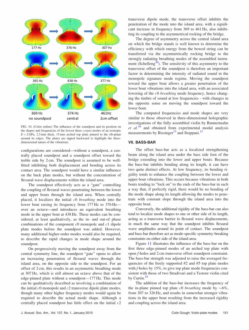
Figure 11 illustrates the influence of the bass-bar on the
first three edge-pinned modes of an arched top plate with
open f-holes and 2 cm transverse offset soundpost constraint.
The bass-bar strength was adjusted to raise the averaged fre-
quencies of the freely supported #2 and #5 top plate modes
with f-holes by 15%, to give top plate mode frequencies con-
sistent with those of two Stradivari and a Testore violin cited
by Curtin.25
The addition of the bass-bar increases the frequency of
the in-plane pinned top plate c0 breathing mode by �6%,
from 307 to 326 Hz, and results in somewhat stronger vibra-
tions in the upper bout resulting from the increased rigidity
and coupling across the island area.
FIG. 10. (Color online) The influence of the soundpost and its position on
the shapes and frequencies of the lowest three corpus modes of an isotropic
E¼ 2 GPa, 2.5 mm thick, 15 mm arched top plate pinned to the rib-plane
around its edges. The plates are tipped backward to highlight the three-
dimensional nature of the vibrations.
J. Acoust. Soc. Am., Vol. 137, No. 1, January 2015 Colin Gough: Violin plate modes 151
The bass-bar introduces a slight decrease in the ampli-
tude on the bass side of the lower bout of the b1 longitudinal
dipole plate mode, because it inhibits bending along its
length resulting in an increase in frequency from 377 to
403 Hz. It has a smaller influence on the b2 lower bout trans-
verse dipole mode raising its frequency from 461 to 481 Hz.
This results from the inhibition of bending along its length,
which tends to introduce a node along its length dividing the
vibrating areas into areas of different size.
The bass-bar has a stronger influence on higher fre-
quency mode shapes, as the flexural standing waves in the
upper and lower bouts adjust their positions and shapes to
accommodate the increased rigidity along the length of the
bass-bar, but with relatively small changes in modal frequen-
cies. Local patches to strengthen cracks and local gradua-
tions in thickness will have a similar small influence on local
mode shapes, but only a small influence on specific mode
frequencies and the averaged spacing of modes.
These computations are consistent with earlier FEA
computational studies4,19 confirming earlier measurements
by Bissinger.31 Such measurements demonstrated that tuning
the bass-bar could restore the freely supported plate mode #2
and #5 frequencies and mode shapes back to those of the
“ideally” tuned plates before the f-holes were cut. However,
it is not obvious why this should necessarily optimize the
acoustic properties, when the plates are coupled together in
the assembled instrument.
When the plates are coupled together in the assembled
instrument, the resulting c0 and c4 breathing modes will also
interact with the air inside the cavity, primarily by their cou-
pling to the a0 Helmholtz f-hole resonance. This coupling
results in a further increase in frequency of the c0 corpusbreathing mode vibrations toward a typical 450–500 Hz
frequency range, where the c0 corpus breathing mode cou-
ples with the bending plate mode to form the strongly radiat-
ing B1– and B1þ signature modes. This will be described
with computations of the radiated sound in the signature
mode regime and its strong dependence on soundpost posi-
tion in a subsequent paper on the shell modes of the violin
body with non-identical plates coupled together by thin ribs.
ACKNOWLEDGMENTS
Valuable discussions with the distinguished violin
makers Joseph Curtin, George Stoppani, and Sam
Zygmuntowicz and acousticians Evan Davis and Jim
Woodhouse are gratefully acknowledged.
1C. M. Hutchins, “A history of violin research,” J. Acoust. Soc. Am. 73,
1421�1440 (1983).2C. M. Hutchins and V. Benade, eds., Research Papers in Violin Acoustics,1975�1993, Vols. 1 & 2 (Acoustical Society of America, Washington,
D.C., 1996).3G. Knott, “A modal analysis of the violin,” Master’s thesis, Naval
Postgraduate School, Monterey, CA, 1987, reprinted in Ref. 2, pp.
508�549.4G. Roberts, “Finite element analysis of the violin,” Ph.D. thesis,
University of Cardiff, UK, 1986, part reprinted in Ref. 2, pp. 575�590.5J. Bretos, C. Santamaria, and J. A. Moral, “Vibrational patterns and fre-
quency responses of the free plates and box of a violin obtained by finite
element analysis,” J. Acoust. Soc. Am. 105, 1942�1950 (1999).6O. Rodgers and P. Anderson, “Finite element analysis of violin corpus,”
Catgut Acoust. Soc. J. 4, 13�26 (2001). pdf copies of all Catgut Journals
can be downloaded free of charge from Stanford University Music Library
at https://ccrma.stanford.edu/marl/CASL/CASLhome.html.7E. Jansson, N.-E. Molin, and H. Sundin, “Resonances of a violin body
studied by hologram interferometry and acoustical methods,” Phys. Scr. 2,
243�256 (1970).8E. Jansson, N.-E. Molin, and H. O. Saldner, “On eigen modes of the vio-
lin—Electronic holography and admittance measurements,” J. Acoust.
Soc. Am. 95(2), 1100�1105 (1994).9N.-E. Molin, A. O. Wahlin, and E. Jansson, “Transient wave response of
the violin body,” J. Acoust. Soc. Am. 88(5), 2479�2481 (1990).10K. D. Marshall, “Modal analysis of a violin,” J. Acoust. Soc. Am. 77,
695�709 (1985).11G. Bissinger, “Structural acoustics of good and bad violins,” J. Acoust.
Soc. Am. 124(3), 1764�1773 (2008).12G. Stoppani, “Acoustic measurements in the workshop,” Proc.
SMAC2013, Stockholm, Sweden (2013), pp. 16�23.13S. Zygmuntowicz and G. Bissinger, “Strad3D,” a 2 DVD set describing
the Strad3D Project (VSA Oberlin Acoustics, Zygmuntowicz, 2009).14C. Gough, “Vibrational modes of the violin family,” in Proc. SMAC2013,
Stockholm (2013), pp. 66�74.15L. Cremer, The Physics of the Violin (MIT Press, Cambridge, 1983),
Chap. 10, pp. 244�282, translated by J. S. Allen.16A. Runnemalm, N.-E. Molin, and E. Jansson, “On operating deflection
shapes of the violin body including in-plane motions,” J. Acoust. Soc.
Am. 107(6), 3452�3459 (2000).17T. D. Rossing, N.-E. Molin, and A. Runnemalm, “Modal analysis of violin
bodies viewed as three-dimensional structures,” J. Acoust. Soc. Am. 114,
2438 (2003).18C. M. Hutchins, “Physics of violins,” Sci. Am. 207, 78�92 (1962).19O. Rodgers, “The effect of elements of wood stiffness on violin plate
vibration,” J. Catgut Acoust. Soc. (series II) 1, 2�8 (1988). pdf copies of
all Catgut Journals can be downloaded free of charge from Stanford
University Music Library at https://ccrma.stanford.edu/marl/CASL/
CASLhome.html.20N. E. Molin, L.-E. Lindgren, and E. V. Jansson, “Parameters of violin
plates and their influence on the plate modes,” J. Acoust. Soc. Am. 83(1),
281�291 (1988).21COMSOL Multidisciplinary Software (versions 3.1-3.5): Structural
Mechanics, Shell Module.
FIG. 11. (Color online) The influence of the bass-bar on the c0 breathing,
c1 longitudinal, and c2 lower bout transverse dipole modes of a uniform
thickness, isotropic, 2.5 mm thick, 15 mm arched, edge-pinned top plate
with a soundpost constraint inhibiting displacement and bending, offset
transversely 20 mm from the center.
152 J. Acoust. Soc. Am., Vol. 137, No. 1, January 2015 Colin Gough: Violin plate modes
22M. McIntyre and J. Woodhouse, “On measuring the elastic and damping con-
stants of orthotropic sheet materials,” Acta Metall. 36, 1397�1416 (1988).23N. Fletcher and T. Rossing, The Physics of Musical Instruments, 2nd ed.
(Springer-Verlag, New York, 1998).24An approach suggested by the distinguished violin maker Sam
Zygmuntowicz.25J. Curtin, “Tap tones and weights of old Italian violin tops,” Vln. Soc.
Am. Pap. 1, 1�13 (2006). pdf copies of Violin Society of America
journals are available from http://tarisio.com/cozio-archive/VSA-
archive/.26E. Davis, “On the effective material properties of violin plates,” in Proc.
SMAC2013, Stockholm, 9�15 (2013). pdf of journal available at http://
vsa.tarisio.com/.27C. M. Hutchings, “A rationale for bi-tri octave plate tuning,” Catgut
Acoust. Soc. J. (series II) 1(8), 36�37 (1991). pdf copies of all Catgut
Journals can be downloaded free of charge from Stanford University
Music Library at https://ccrma.stanford.edu/marl/CASL/CASLhome.html.28J. Loen, “Thickness graduation mapping, surprises and discoveries,” J. Vln.
Soc. Am. 19, 41�66 (2003). pdf copies of Violin Society of America jour-
nals are available from http://tarisio.com/cozio-archive/VSA-archive/.29P. M. Morse and H. Feshbach, Methods of Theoretical Physics (McGraw-
Hill, Tokyo, 1953), Sec. 5.3, Hankel functions, pp. 623-624.30J. C. Schelleng, “The action of the soundpost,” Catgut Acoust. Soc.
Newsl. 16, 11�15 (1971). pdf copies of all Catgut Journals can be down-
loaded free of charge from Stanford University Music Library at https://
ccrma.stanford.edu/marl/CASL/CASLhome.html.31G. Bissinger, “Tuning the bass bar in a violin plate,” Catgut Acoust. Soc.
Newsl. 26, 10�12 (1976). pdf copies of all Catgut Journals can be down-
loaded free of charge from Stanford University Music Library at https://
ccrma.stanford.edu/marl/CASL/CASLhome.html.
J. Acoust. Soc. Am., Vol. 137, No. 1, January 2015 Colin Gough: Violin plate modes 153


![Violin Concerto in D Major, Op. 77 [Op. 77] · Title: Violin Concerto in D Major, Op. 77 [Op. 77] Author: Brahms, Johannes - Editeur: Leipzig: Breitkopf & Härtel, 1926-27. Plate](https://img.pdfslide.us/doc/110x75/5fc6ed87850b4268e654b701/violin-concerto-in-d-major-op-77-op-77-title-violin-concerto-in-d-major-op.jpg)


![Cantabile for Violin and Guitar [MS 109, Op.17]...Title Cantabile for Violin and Guitar [MS 109, Op.17] Author Paganini, Niccolo - Publisher: Vienna: Universal Edition, 1922. Plate](https://img.pdfslide.us/doc/110x75/5e2c3e7f5739104c6a51862b/cantabile-for-violin-and-guitar-ms-109-op17-title-cantabile-for-violin-and.jpg)