Embed Size (px)
Citation preview
In this tutorial you will create a 3D sign in ArtCAM Express or ArtCAM
Insignia using different toolpaths. You will start by simulating previously
calculated toolpaths so you can see the finished piece, and then go on to
create, calculate and simulate your own toolpaths in order to understand the
machining process.
Simulating the toolpaths You will begin by opening a previously saved ArtCAM model, and then
simulating the calculated toolpaths included.
1. From the Start panel, click Open Model. The Open dialog
box is displayed.
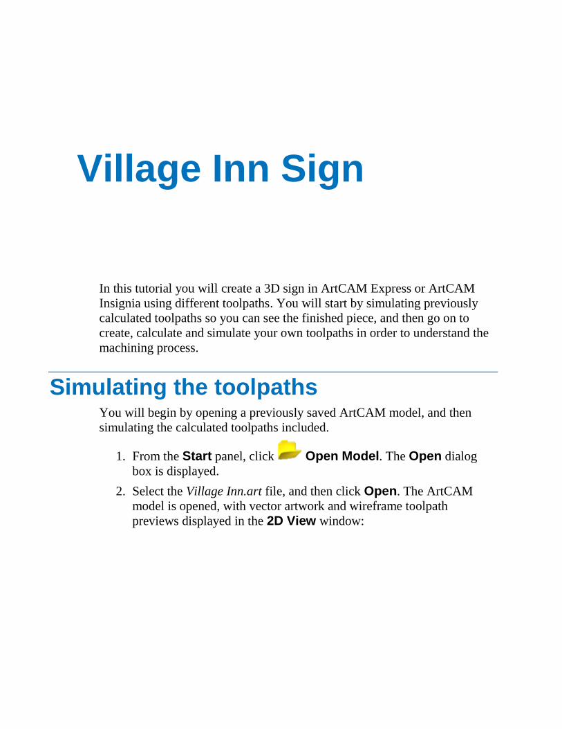
2. Select the Village Inn.art file, and then click Open. The ArtCAM
model is opened, with vector artwork and wireframe toolpath
previews displayed in the 2D View window:
Village Inn Sign
3. Press the F3 key to display the 3D View window. The material block
is displayed along with a textured relief. This relief is used as a
textured background in the finished sign.
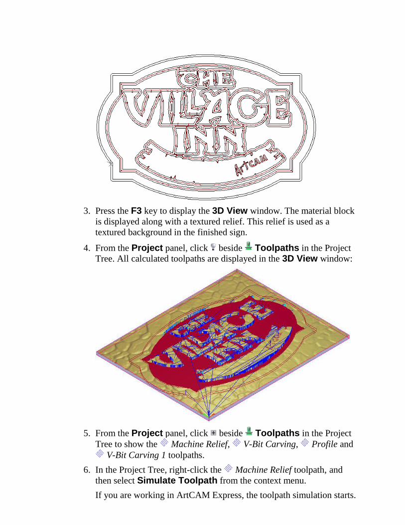
4. From the Project panel, click beside Toolpaths in the Project
Tree. All calculated toolpaths are displayed in the 3D View window:
5. From the Project panel, click beside Toolpaths in the Project
Tree to show the Machine Relief, V-Bit Carving, Profile and
V-Bit Carving 1 toolpaths.
6. In the Project Tree, right-click the Machine Relief toolpath, and
then select Simulate Toolpath from the context menu.
If you are working in ArtCAM Express, the toolpath simulation starts.
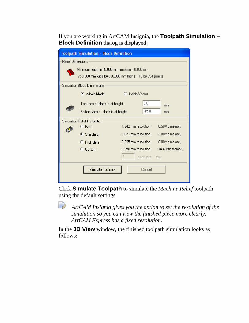
If you are working in ArtCAM Insignia, the Toolpath Simulation – Block Definition dialog is displayed:
Click Simulate Toolpath to simulate the Machine Relief toolpath
using the default settings.
ArtCAM Insignia gives you the option to set the resolution of the
simulation so you can view the finished piece more clearly.
ArtCAM Express has a fixed resolution.
In the 3D View window, the finished toolpath simulation looks as
follows:
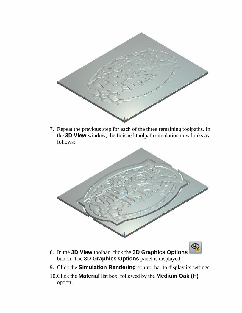
7. Repeat the previous step for each of the three remaining toolpaths. In
the 3D View window, the finished toolpath simulation now looks as
follows:
8. In the 3D View toolbar, click the 3D Graphics Options
button. The 3D Graphics Options panel is displayed.
9. Click the Simulation Rendering control bar to display its settings.
10. Click the Material list box, followed by the Medium Oak (H) option.
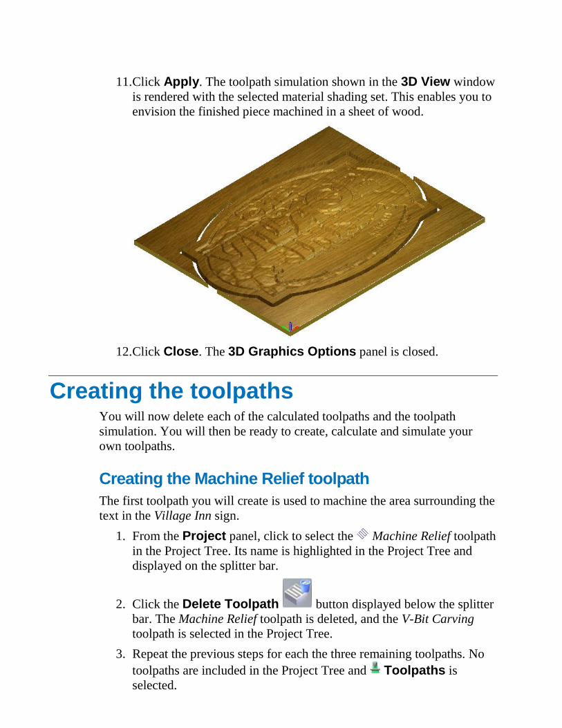
11. Click Apply. The toolpath simulation shown in the 3D View window
is rendered with the selected material shading set. This enables you to
envision the finished piece machined in a sheet of wood.
12. Click Close. The 3D Graphics Options panel is closed.
Creating the toolpaths You will now delete each of the calculated toolpaths and the toolpath
simulation. You will then be ready to create, calculate and simulate your
own toolpaths.
Creating the Machine Relief toolpath
The first toolpath you will create is used to machine the area surrounding the
text in the Village Inn sign.
1. From the Project panel, click to select the Machine Relief toolpath
in the Project Tree. Its name is highlighted in the Project Tree and
displayed on the splitter bar.
2. Click the Delete Toolpath button displayed below the splitter
bar. The Machine Relief toolpath is deleted, and the V-Bit Carving
toolpath is selected in the Project Tree.
3. Repeat the previous steps for each the three remaining toolpaths. No
toolpaths are included in the Project Tree and Toolpaths is
selected.
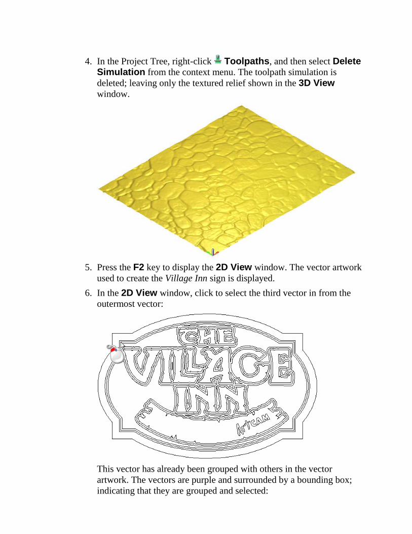
4. In the Project Tree, right-click Toolpaths, and then select Delete Simulation from the context menu. The toolpath simulation is
deleted; leaving only the textured relief shown in the 3D View
window.
5. Press the F2 key to display the 2D View window. The vector artwork
used to create the Village Inn sign is displayed.
6. In the 2D View window, click to select the third vector in from the
outermost vector:
This vector has already been grouped with others in the vector
artwork. The vectors are purple and surrounded by a bounding box;
indicating that they are grouped and selected:
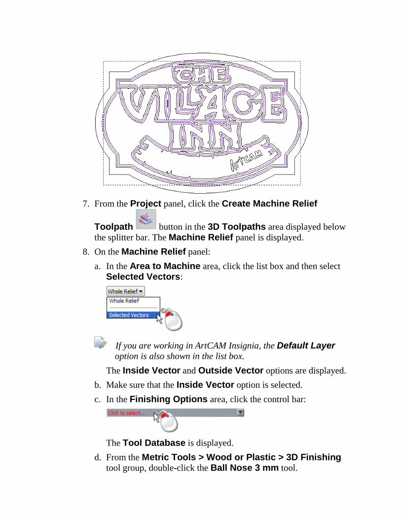
7. From the Project panel, click the Create Machine Relief
Toolpath button in the 3D Toolpaths area displayed below
the splitter bar. The Machine Relief panel is displayed.
8. On the Machine Relief panel:
a. In the Area to Machine area, click the list box and then select
Selected Vectors:
If you are working in ArtCAM Insignia, the Default Layer
option is also shown in the list box.
The Inside Vector and Outside Vector options are displayed.
b. Make sure that the Inside Vector option is selected.
c. In the Finishing Options area, click the control bar:
The Tool Database is displayed.
d. From the Metric Tools > Wood or Plastic > 3D Finishing
tool group, double-click the Ball Nose 3 mm tool.
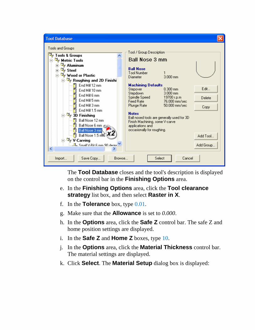
The Tool Database closes and the tool's description is displayed
on the control bar in the Finishing Options area.
e. In the Finishing Options area, click the Tool clearance strategy list box, and then select Raster in X.
f. In the Tolerance box, type 0.01.
g. Make sure that the Allowance is set to 0.000.
h. In the Options area, click the Safe Z control bar. The safe Z and
home position settings are displayed.
i. In the Safe Z and Home Z boxes, type 10.
j. In the Options area, click the Material Thickness control bar.
The material settings are displayed.
k. Click Select. The Material Setup dialog box is displayed:
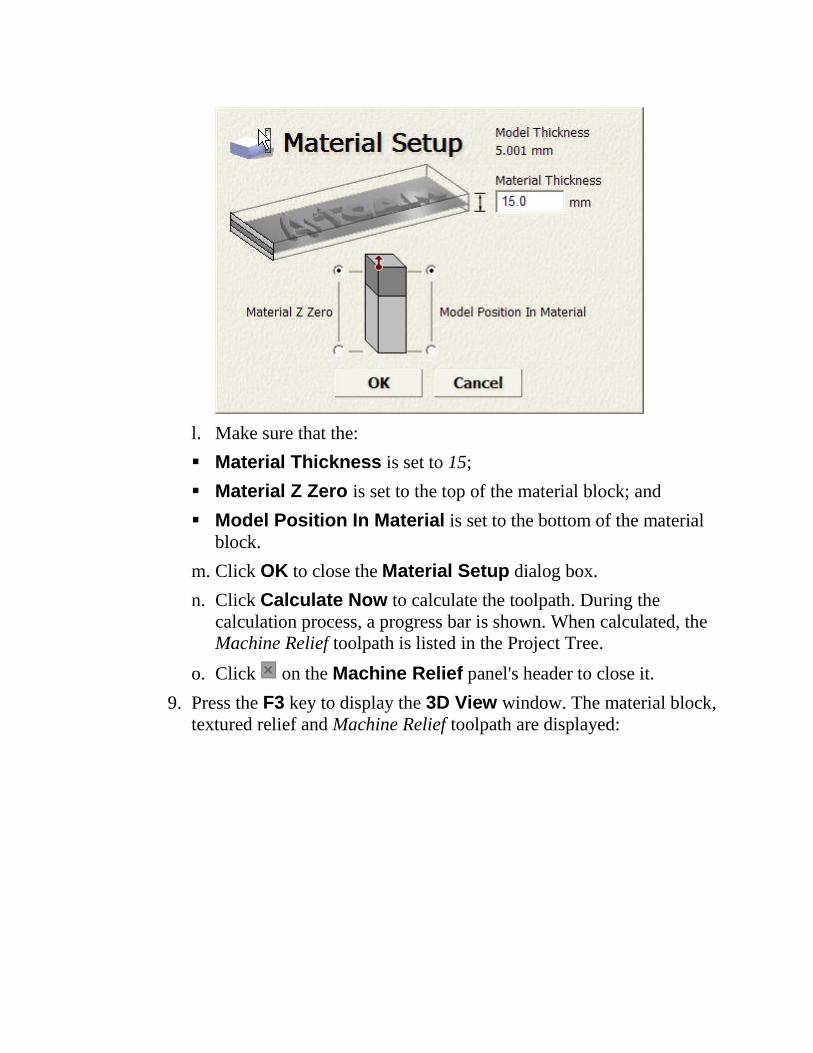
l. Make sure that the:
Material Thickness is set to 15;
Material Z Zero is set to the top of the material block; and
Model Position In Material is set to the bottom of the material
block.
m. Click OK to close the Material Setup dialog box.
n. Click Calculate Now to calculate the toolpath. During the
calculation process, a progress bar is shown. When calculated, the
Machine Relief toolpath is listed in the Project Tree.
o. Click on the Machine Relief panel's header to close it.
9. Press the F3 key to display the 3D View window. The material block,
textured relief and Machine Relief toolpath are displayed:
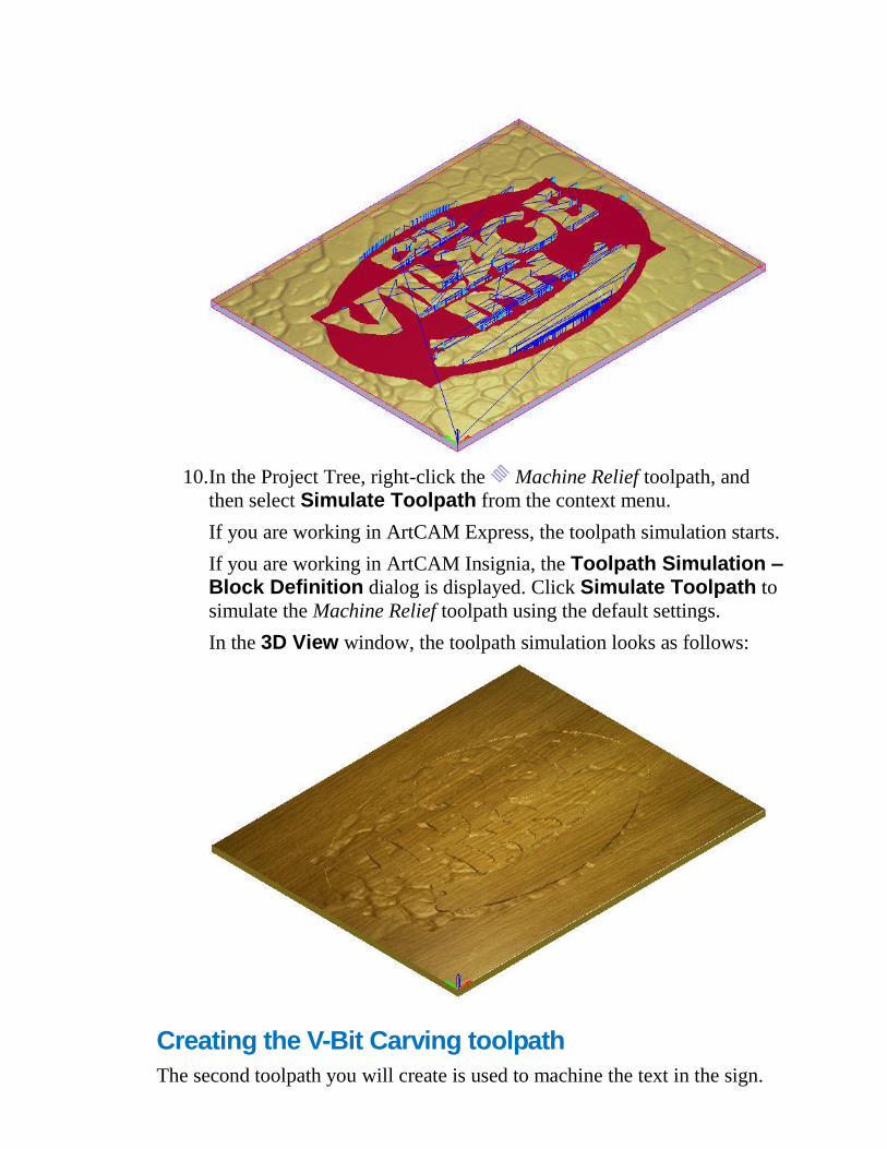
10. In the Project Tree, right-click the Machine Relief toolpath, and
then select Simulate Toolpath from the context menu.
If you are working in ArtCAM Express, the toolpath simulation starts.
If you are working in ArtCAM Insignia, the Toolpath Simulation – Block Definition dialog is displayed. Click Simulate Toolpath to
simulate the Machine Relief toolpath using the default settings.
In the 3D View window, the toolpath simulation looks as follows:
Creating the V-Bit Carving toolpath
The second toolpath you will create is used to machine the text in the sign.
1. Press the F2 key to display the 2D View window. The third vector in
from the outermost vector is selected.
2. In the 2D View window, click anywhere in the empty model area (the
white rectangle) to deselect the vector used when creating the
Machine Relief toolpath.
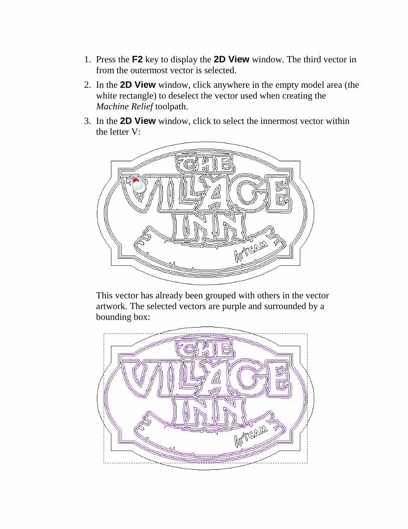
3. In the 2D View window, click to select the innermost vector within
the letter V:
This vector has already been grouped with others in the vector
artwork. The selected vectors are purple and surrounded by a
bounding box:
4. From the Project panel, click the Create V-Bit Carving Toolpath
button in the 2D Toolpaths area displayed below the splitter
bar. The V-Bit Carving panel is displayed.
5. In the Vector Association area, make sure that Selected Vectors
is selected in the list box.
6. In the Cutting Depth area:
a. Make sure that the Start Depth is set to 0.000.
b. Select the Limit tool maximum depth check box.
c. Type 10 in the Maximum Depth box.
d. Make sure that the Tolerance is set to 0.01.
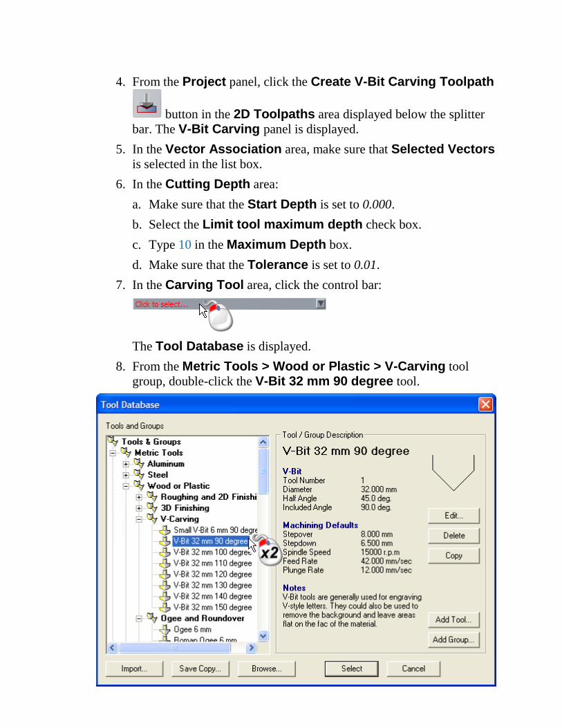
7. In the Carving Tool area, click the control bar:
The Tool Database is displayed.
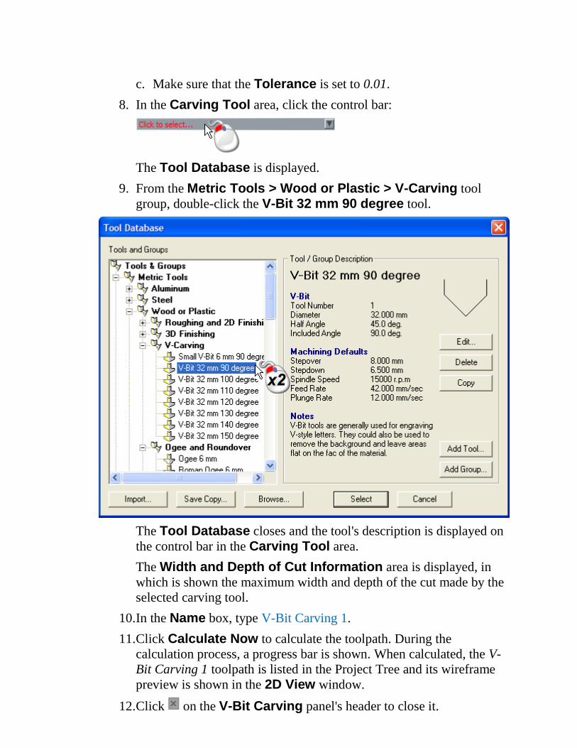
8. From the Metric Tools > Wood or Plastic > V-Carving tool
group, double-click the V-Bit 32 mm 90 degree tool.
The Tool Database closes and the tool's description is displayed on
the control bar in the Carving Tool area.
The Width and Depth of Cut Information area is displayed, in
which is shown the maximum width and depth of the cut made by the
selected carving tool.
9. Click Calculate Now to calculate the toolpath. During the
calculation process, a progress bar is shown. When calculated, the V-
Bit Carving toolpath is listed in the Project Tree and its wireframe
preview is shown in the 2D View window.
10. Click on the V-Bit Carving panel's header to close it.
11. Press the F3 key to display the 3D View window. The V-Bit Carving
toolpath is displayed along with the simulated Machine Relief
toolpath.
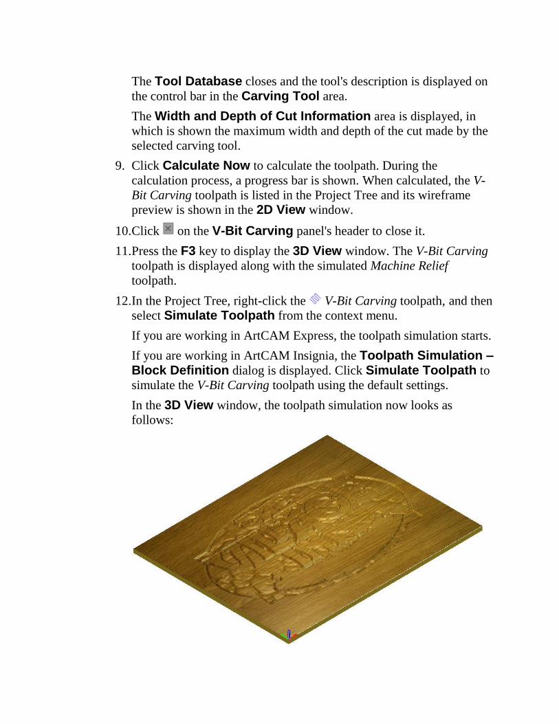
12. In the Project Tree, right-click the V-Bit Carving toolpath, and then
select Simulate Toolpath from the context menu.
If you are working in ArtCAM Express, the toolpath simulation starts.
If you are working in ArtCAM Insignia, the Toolpath Simulation – Block Definition dialog is displayed. Click Simulate Toolpath to
simulate the V-Bit Carving toolpath using the default settings.
In the 3D View window, the toolpath simulation now looks as
follows:
Creating the Profiling toolpath
The third toolpath you will create is used to profile the boundary of the
Village Inn sign.
1. Press the F2 key to display the 2D View window. The V-Bit Carving
toolpath's wireframe preview is shown along with the vector artwork.
2. From the Project panel, click to the right of V-Bit Carving in
the Project Tree. The wireframe toolpath preview is hidden in the 2D View window.
3. In the 2D View window, click anywhere in the empty model area (the
white rectangle) to deselect the vector artwork used when creating the
V-Bit Carving toolpath.
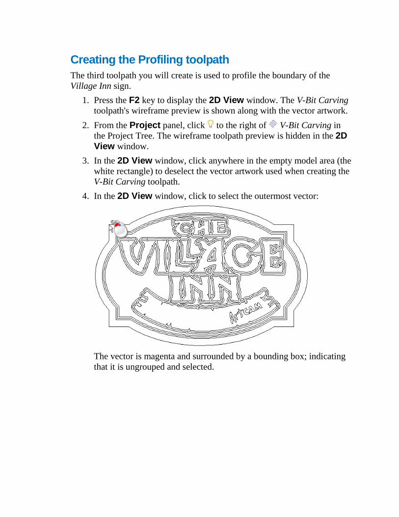
4. In the 2D View window, click to select the outermost vector:
The vector is magenta and surrounded by a bounding box; indicating
that it is ungrouped and selected.
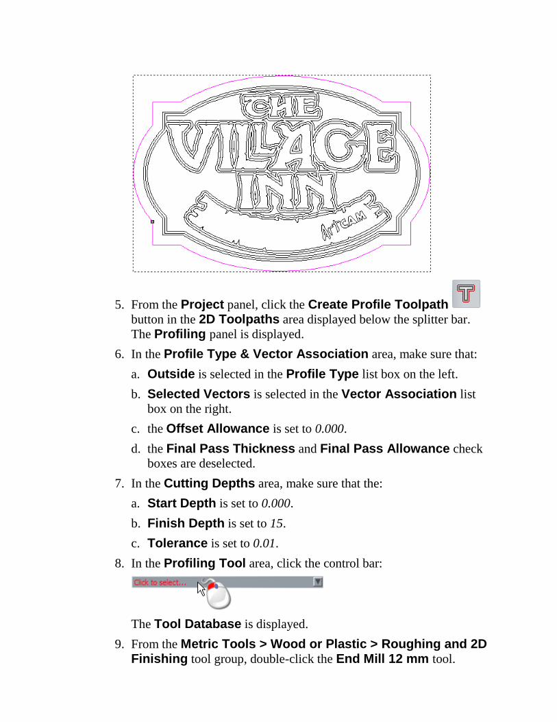
5. From the Project panel, click the Create Profile Toolpath
button in the 2D Toolpaths area displayed below the splitter bar.
The Profiling panel is displayed.
6. In the Profile Type & Vector Association area, make sure that:
a. Outside is selected in the Profile Type list box on the left.
b. Selected Vectors is selected in the Vector Association list
box on the right.
c. the Offset Allowance is set to 0.000.
d. the Final Pass Thickness and Final Pass Allowance check
boxes are deselected.
7. In the Cutting Depths area, make sure that the:
a. Start Depth is set to 0.000.
b. Finish Depth is set to 15.
c. Tolerance is set to 0.01.
8. In the Profiling Tool area, click the control bar:
The Tool Database is displayed.
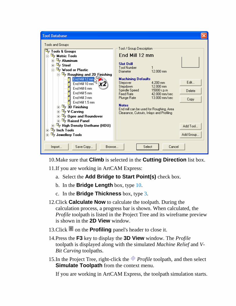
9. From the Metric Tools > Wood or Plastic > Roughing and 2D Finishing tool group, double-click the End Mill 12 mm tool.
10. Make sure that Climb is selected in the Cutting Direction list box.
11. If you are working in ArtCAM Express:
a. Select the Add Bridge to Start Point(s) check box.
b. In the Bridge Length box, type 10.
c. In the Bridge Thickness box, type 3.
12. Click Calculate Now to calculate the toolpath. During the
calculation process, a progress bar is shown. When calculated, the
Profile toolpath is listed in the Project Tree and its wireframe preview
is shown in the 2D View window.
13. Click on the Profiling panel's header to close it.
14. Press the F3 key to display the 3D View window. The Profile
toolpath is displayed along with the simulated Machine Relief and V-
Bit Carving toolpaths.
15. In the Project Tree, right-click the Profile toolpath, and then select
Simulate Toolpath from the context menu.
If you are working in ArtCAM Express, the toolpath simulation starts.
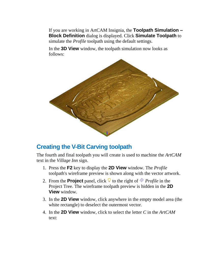
If you are working in ArtCAM Insignia, the Toolpath Simulation – Block Definition dialog is displayed. Click Simulate Toolpath to
simulate the Profile toolpath using the default settings.
In the 3D View window, the toolpath simulation now looks as
follows:
Creating the V-Bit Carving toolpath
The fourth and final toolpath you will create is used to machine the ArtCAM
text in the Village Inn sign.
1. Press the F2 key to display the 2D View window. The Profile
toolpath's wireframe preview is shown along with the vector artwork.
2. From the Project panel, click to the right of Profile in the
Project Tree. The wireframe toolpath preview is hidden in the 2D View window.
3. In the 2D View window, click anywhere in the empty model area (the
white rectangle) to deselect the outermost vector.
4. In the 2D View window, click to select the letter C in the ArtCAM
text:
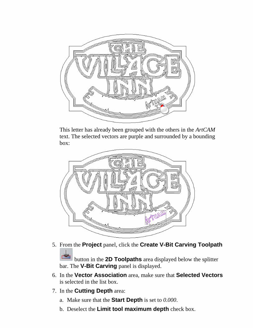
This letter has already been grouped with the others in the ArtCAM
text. The selected vectors are purple and surrounded by a bounding
box:
5. From the Project panel, click the Create V-Bit Carving Toolpath
button in the 2D Toolpaths area displayed below the splitter
bar. The V-Bit Carving panel is displayed.
6. In the Vector Association area, make sure that Selected Vectors
is selected in the list box.
7. In the Cutting Depth area:
a. Make sure that the Start Depth is set to 0.000.
b. Deselect the Limit tool maximum depth check box.
c. Make sure that the Tolerance is set to 0.01.
8. In the Carving Tool area, click the control bar:
The Tool Database is displayed.
9. From the Metric Tools > Wood or Plastic > V-Carving tool
group, double-click the V-Bit 32 mm 90 degree tool.
The Tool Database closes and the tool's description is displayed on
the control bar in the Carving Tool area.
The Width and Depth of Cut Information area is displayed, in
which is shown the maximum width and depth of the cut made by the
selected carving tool.
10. In the Name box, type V-Bit Carving 1.
11. Click Calculate Now to calculate the toolpath. During the
calculation process, a progress bar is shown. When calculated, the V-
Bit Carving 1 toolpath is listed in the Project Tree and its wireframe
preview is shown in the 2D View window.
12. Click on the V-Bit Carving panel's header to close it.
13. Press the F3 key to display the 3D View window. The V-Bit Carving
toolpath is displayed along with the simulated Machine Relief, V-Bit
Carving and Profile toolpaths.
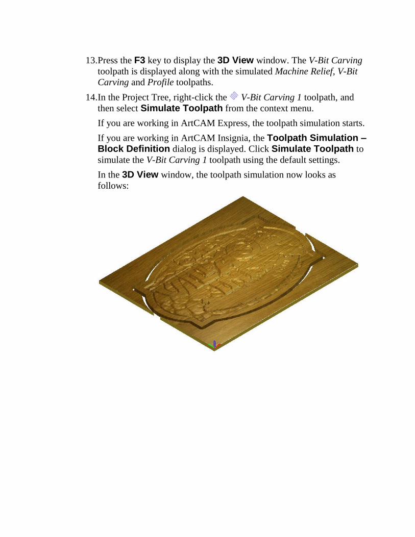
14. In the Project Tree, right-click the V-Bit Carving 1 toolpath, and
then select Simulate Toolpath from the context menu.
If you are working in ArtCAM Express, the toolpath simulation starts.
If you are working in ArtCAM Insignia, the Toolpath Simulation – Block Definition dialog is displayed. Click Simulate Toolpath to
simulate the V-Bit Carving 1 toolpath using the default settings.
In the 3D View window, the toolpath simulation now looks as
follows: