Embed Size (px)
Citation preview

VIIRS SDR User’s Guide
36
Appendix A – SDR Data Contents and Related Information
VIIRS M-Band Data Content Summary
The VIIRS M-Band SDR HDF5 data array structures are summarized below.
VIIRS M-Band SDRs Data Content Summary
Name Description Data Type Bands
Aggregate Dimensions (N =
Number of Granules)
Granule Dimensions Units
Radiance
Calibrated Top of Atmosphere (TOA) Radiance for each VIIRS pixel
32-bit floating point
M3-M5, M7, M13
[N*768, 3200] [768,3200] W/(m2 sr m) unsigned
16-bit integer
M1, M2, M6, M8-M12, M14-M16
Reflectance Calibrated TOA Reflectance for each VIIRS pixel
unsigned 16-bit integer
M1 – M11 [N*768, 3200] [768,3200] unitless
BrightnessTemperature Calibrated TOA Brightness Temperature for each VIIRS pixel
32-bit floating point
M13
[N*768, 3200] [768,3200] kelvin unsigned 16-bit integer
M12, M14 – M16
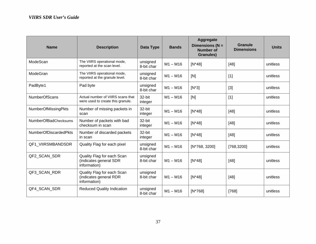
VIIRS SDR User’s Guide
37
Name Description Data Type Bands
Aggregate Dimensions (N =
Number of Granules)
Granule Dimensions Units
ModeScan The VIIRS operational mode, reported at the scan level.
unsigned 8-bit char M1 – M16 [N*48] [48] unitless
ModeGran The VIIRS operational mode, reported at the granule level.
unsigned 8-bit char M1 – M16 [N] [1] unitless
PadByte1 Pad byte unsigned 8-bit char M1 – M16 [N*3] [3] unitless
NumberOfScans Actual number of VIIRS scans that were used to create this granule.
32-bit integer
M1 – M16 [N] [1] unitless
NumberOfMissingPkts Number of missing packets in scan
32-bit integer M1 – M16 [N*48] [48] unitless
NumberOfBadChecksums Number of packets with bad checksum in scan
32-bit integer M1 – M16 [N*48] [48] unitless
NumberOfDiscardedPkts Number of discarded packets in scan
32-bit integer M1 – M16 [N*48] [48] unitless
QF1_VIIRSMBANDSDR Quality Flag for each pixel unsigned 8-bit char M1 – M16 [N*768, 3200] [768,3200] unitless
QF2_SCAN_SDR Quality Flag for each Scan (indicates general SDR information)
unsigned 8-bit char M1 – M16 [N*48] [48] unitless
QF3_SCAN_RDR Quality Flag for each Scan (indicates general RDR information)
unsigned 8-bit char M1 – M16 [N*48] [48] unitless
QF4_SCAN_SDR Reduced Quality Indication unsigned 8-bit char M1 – M16 [N*768] [768] unitless

VIIRS SDR User’s Guide
38
Name Description Data Type Bands
Aggregate Dimensions (N =
Number of Granules)
Granule Dimensions Units
QF5_GRAN_BADDETECTOR
Quality Flag – Bad detector unsigned 8-bit char M1 – M16 [N*16] [16] unitless
RadianceFactors Radiance scale and offset: first array element = scale second array element = offset
32-bit floating point
M1, M2, M6, M8-M12, M14-M16
[N] [2] unitless, W/(m2 sr m)
ReflectanceFactors Reflectance scale and offset: first array element = scale second array element = offset
32-bit floating point M1-M11 [N] [2] unitless,
unitless
BrightnessTemperatureFactors
Brightness Temperature scale and offset: first array element = scale second array element = offset
32-bit floating point M12, M14 –
M16 [N] [2] unitless, kelvin
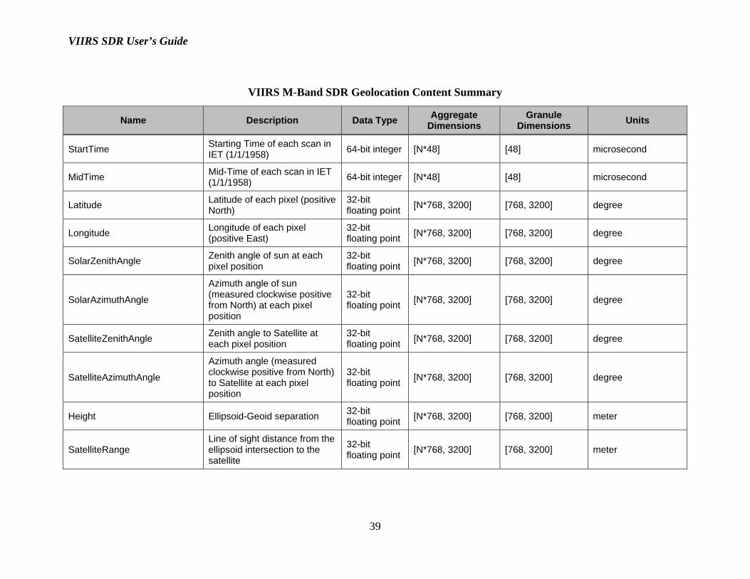
VIIRS M-Band Geolocation Content Summary
The VIIRS M-Band SDR geolocation data arrays structures are summarized below:
VIIRS SDR User’s Guide
39
VIIRS M-Band SDR Geolocation Content Summary
Name Description Data Type Aggregate Dimensions
Granule Dimensions Units
StartTime Starting Time of each scan in IET (1/1/1958) 64-bit integer [N*48] [48] microsecond
MidTime Mid-Time of each scan in IET (1/1/1958) 64-bit integer [N*48] [48] microsecond
Latitude Latitude of each pixel (positive North)
32-bit floating point [N*768, 3200] [768, 3200] degree
Longitude Longitude of each pixel (positive East)
32-bit floating point [N*768, 3200] [768, 3200] degree
SolarZenithAngle Zenith angle of sun at each pixel position
32-bit floating point [N*768, 3200] [768, 3200] degree
SolarAzimuthAngle
Azimuth angle of sun (measured clockwise positive from North) at each pixel position
32-bit floating point [N*768, 3200] [768, 3200] degree
SatelliteZenithAngle Zenith angle to Satellite at each pixel position
32-bit floating point [N*768, 3200] [768, 3200] degree
SatelliteAzimuthAngle
Azimuth angle (measured clockwise positive from North) to Satellite at each pixel position
32-bit floating point [N*768, 3200] [768, 3200] degree
Height Ellipsoid-Geoid separation 32-bit floating point [N*768, 3200] [768, 3200] meter
SatelliteRange Line of sight distance from the ellipsoid intersection to the satellite
32-bit floating point [N*768, 3200] [768, 3200] meter

VIIRS SDR User’s Guide
40
Name Description Data Type Aggregate Dimensions
Granule Dimensions Units
SCPosition Spacecraft position in ECR Coordinates (X, Y, Z) at the mid-time of scan
32-bit floating point [N*48, 3] [48, 3] meter
SCVelocity Spacecraft velocity in ECR Coordinates (dx/dt, dy/dt, dz/dt) at the mid- time of scan
32-bit floating point [N*48, 3] [48, 3] m/s
SCAttitude Spacecraft attitude with respect to Geodetic Reference Frame Coordinates (roll, pitch, yaw) at the midtime of scan
32-bit floating point
[N*48, 3] [48, 3] arcsecond
SCSolarZenithAngle The angle from the normal vector of the Solar Diffuser surface (z-axis of the solar diffuser frame) to the solar vector
32-bit floating point [N*48] [48] degree
SCSolarAzimuthAngle
The angle from the Solar Diffuser reference frame x-axis to the projection of the solar vector onto the solar diffuser surface (x-y plane), measured counterclockwise (observer looking toward the SD surface)
32-bit floating point [N*48] [48] degree
ModeScan The VIIRS operational mode, reported at the scan level.
unsigned 8-bit char [N*48] [48] unitless
ModeGran The VIIRS operational mode, reported at the granule level.
unsigned 8-bit char [N] [1] unitless
PadByte1 Pad byte unsigned 8-bit char [N*3] [3] unitless
VIIRS SDR User’s Guide
41
Name Description Data Type Aggregate Dimensions
Granule Dimensions Units
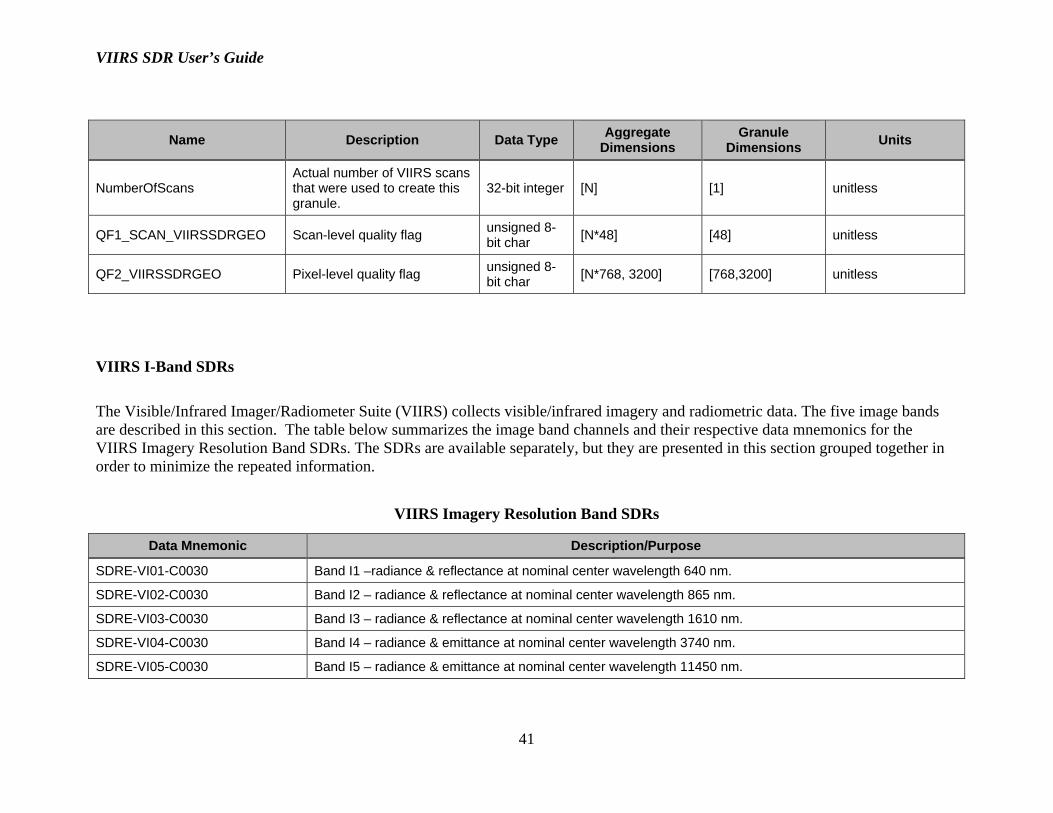
NumberOfScans Actual number of VIIRS scans that were used to create this granule.
32-bit integer [N] [1] unitless
QF1_SCAN_VIIRSSDRGEO Scan-level quality flag unsigned 8-bit char [N*48] [48] unitless
QF2_VIIRSSDRGEO Pixel-level quality flag unsigned 8-bit char [N*768, 3200] [768,3200] unitless
VIIRS I-Band SDRs The Visible/Infrared Imager/Radiometer Suite (VIIRS) collects visible/infrared imagery and radiometric data. The five image bands are described in this section. The table below summarizes the image band channels and their respective data mnemonics for the VIIRS Imagery Resolution Band SDRs. The SDRs are available separately, but they are presented in this section grouped together in order to minimize the repeated information.
VIIRS Imagery Resolution Band SDRs
Data Mnemonic Description/Purpose
SDRE-VI01-C0030 Band I1 –radiance & reflectance at nominal center wavelength 640 nm.
SDRE-VI02-C0030 Band I2 – radiance & reflectance at nominal center wavelength 865 nm.
SDRE-VI03-C0030 Band I3 – radiance & reflectance at nominal center wavelength 1610 nm.
SDRE-VI04-C0030 Band I4 – radiance & emittance at nominal center wavelength 3740 nm.
SDRE-VI05-C0030 Band I5 – radiance & emittance at nominal center wavelength 11450 nm.

VIIRS SDR User’s Guide
42
The VIIRS I-Band SDR HDF5 data array structures are summarized below, followed by presentation of the UML diagrams for each designated band.
VIIRS I-Band SDR Data Content Summary
Name Description Data Type Bands
Aggregate Dimensions (N = Number of Granules)
Granule Dimensions Units
Radiance
Calibrated Top of Atmosphere (TOA) Radiance for each VIIRS pixel
unsigned 16-bit integer
I1-I5 [N*1536, 6400] [1536, 6400] W/(m2
sr m)
Reflectance
Calibrated Top of Atmosphere (TOA) Reflectance for each VIIRS pixel
unsigned 16-bit integer
I1-I3 [N*1536, 6400] [1536, 6400] unitless
BrightnessTemperature
Calibrated Top of Atmosphere (TOA) Brightness Temperature for each VIIRS pixel
unsigned 16-bit integer
I4, I5 [N*1536, 6400] [1536, 6400] K
ModeScan
The VIIRS operational mode, reported at the scan level
unsigned 8-bit char I1-I5 [N*48] [48] unitless
ModeGran
The VIIRS operational mode, reported at the granule level
unsigned 8-bit char I1-I5 [N] [1] unitless

VIIRS SDR User’s Guide
43
Name Description Data Type Bands
Aggregate Dimensions (N = Number of Granules)
Granule Dimensions Units
PadByte1 Pad byte unsigned 8-bit char I1-I5 [N*3] [3] unitless
NumberOfScans
Actual number of VIIRS scans that were used to create this granule
32-bit integer I1-I5 [N] [1] unitless
NumberOfMissingPkts
Number of missing packets in scan
32-bit integer I1-I5 [N*48] [48] unitless
NumberOfBadChecksums
Number of packets with bad checksum in scan
32-bit integer I1-I5 [N*48] [48] unitless
NumberOfDiscardedPkts
Number of discarded packets in scan
32-bit integer I1-I5 [N*48] [48] unitless
QF1_VIIRSIBANDSDR
Quality Flag for each pixel
unsigned 8-bit char I1-I5 [N*1536,
6400] [1536, 6400] unitless
QF2_SCAN_SDR
Quality Flag for each Scan (indicates general SDR information)
unsigned 8-bit char I1-I5 [N*48] [48] unitless
QF3_SCAN_RDR
Quality Flag for each Scan (indicates general RDR information)
unsigned 8-bit char I1-I5 [N*48] [48] unitless
QF4_SCAN_SDR
Reduced Quality Indicator
unsigned 8-bit char I1-I5 [N*1536] [1536] unitless

VIIRS SDR User’s Guide
44
Name Description Data Type Bands
Aggregate Dimensions (N = Number of Granules)
Granule Dimensions Units
QF5_GRAN_BADDETECTOR
Quality Flag – Bad detector
unsigned 8-bit char I1-I5 [N*32] [32] unitless
RadianceFactors
Radiance scale and offset: 1st array element = scale 2nd array element = offset
32-bit floating point
I1-I5 [N*2] [2] unitless, W/(m2 sr m)
ReflectanceFactors
Reflectance scale and offset: 1st array element = scale 2nd array element = offset
32-bit floating point
I1-I3 [N*2] [2] unitless, unitless
BrightnessTemperatureFactors
Brightness Temperature scale and offset: 1st array element = scale 2nd array element = offset
32-bit floating point
I4, I5 [N*2] [2] unitless, kelvin
VIIRS I-Band Geolocation Content Summary
The VIIRS I-Band SDR Geolocation arrays structures are summarized in the table below.

VIIRS SDR User’s Guide
45
VIIRS I-Band SDR Geolocation Content Summary
Name Description Data Type Aggregate Dimensions
Granule Dimensions Units
StartTime Starting Time of each scan in IET (1/1/1958)
64-bit integer [N*48] [48] microsecond
MidTime Mid-Time of each scan in IET (1/1/1958)
64-bit integer [N*48] [48] microsecond
Latitude Latitude of each pixel (positive North)
32-bit floating point
[N*1536, 6400] [1536, 6400] degree
Longitude Longitude of each pixel (positive East)
32-bit floating point
[N*1536, 6400] [1536, 6400] degree
SolarZenithAngle Zenith angle of sun at each pixel position
32-bit floating point
[N*1536, 6400] [1536, 6400] degree
SolarAzimuthAngle Azimuth angle of sun (measured clockwise positive from North) at each pixel position
32-bit floating point
[N*1536, 6400] [1536, 6400] degree
SatelliteZenithAngle Zenith angle to Satellite at each pixel position
32-bit floating point
[N*1536, 6400] [1536, 6400] degree
SatelliteAzimuthAngle Azimuth angle (measured clockwise positive from North) to Satellite at each pixel position
32-bit floating point
[N*1536, 6400] [1536, 6400] degree
Height Ellipsoid-Geoid separation
32-bit floating point
[N*1536, 6400] [1536, 6400] meter
SatelliteRange Line of sight distance from the ellipsoid intersection to the satellite
32-bit floating point
[N*1536, 6400] [1536, 6400] meter

VIIRS SDR User’s Guide
46
Name Description Data Type Aggregate Dimensions
Granule Dimensions Units
SCPosition Spacecraft position in ECR Coordinates (X, Y, Z) at the mid-time of scan
32-bit floating point
[N*48, 3] [48, 3] meter
SCVelocity Spacecraft velocity in ECR Coordinates (dx/dt, dy/dt, dz/dt) at the mid-time of scan
32-bit floating point
[N*48, 3] [48, 3] m/s
SCAttitude Spacecraft attitude with respect to Geodetic Reference Frame Coordinates (roll, pitch, yaw) at the mid-time of scan
32-bit floating point
[N*48, 3] [48, 3] arcsecond
SCSolarZenithAngle The angle from the normal vector of the Solar Diffuser surface (z-axis of the solar diffuser frame) to the solar vector
32-bit floating point
[N*48] [48] degree
SCSolarAzimuthAngle The angle from the Solar Diffuser reference frame x-axis to the projection of the solar vector onto the solar diffuser surface (x-y plane), measured counterclockwise (observer looking toward the SD surface)
32-bit floating point
[N*48] [48] degree

VIIRS SDR User’s Guide
47
Name Description Data Type Aggregate Dimensions
Granule Dimensions Units
ModeScan The VIIRS operational mode, reported at the scan level
unsigned 8-bit char
[N*48] [48] unitless
ModeGran The VIIRS operational mode, reported at the granule level
unsigned 8-bit char
[N] [1] unitless
PadByte1 Pad byte unsigned 8-bit char [N*3] [3] unitless
NumberOfScans Actual number of VIIRS scans that were used to create this granule
32-bit integer [N] [1] unitless
QF1_SCAN_VIIRSSDRGEO Scan-level quality flag unsigned 8-bit char [N*48] [48] unitless
QF2_VIIRSSDRGEO Pixel-level quality flag unsigned 8-bit char [N*1536, 6400] [1536,6400] unitless
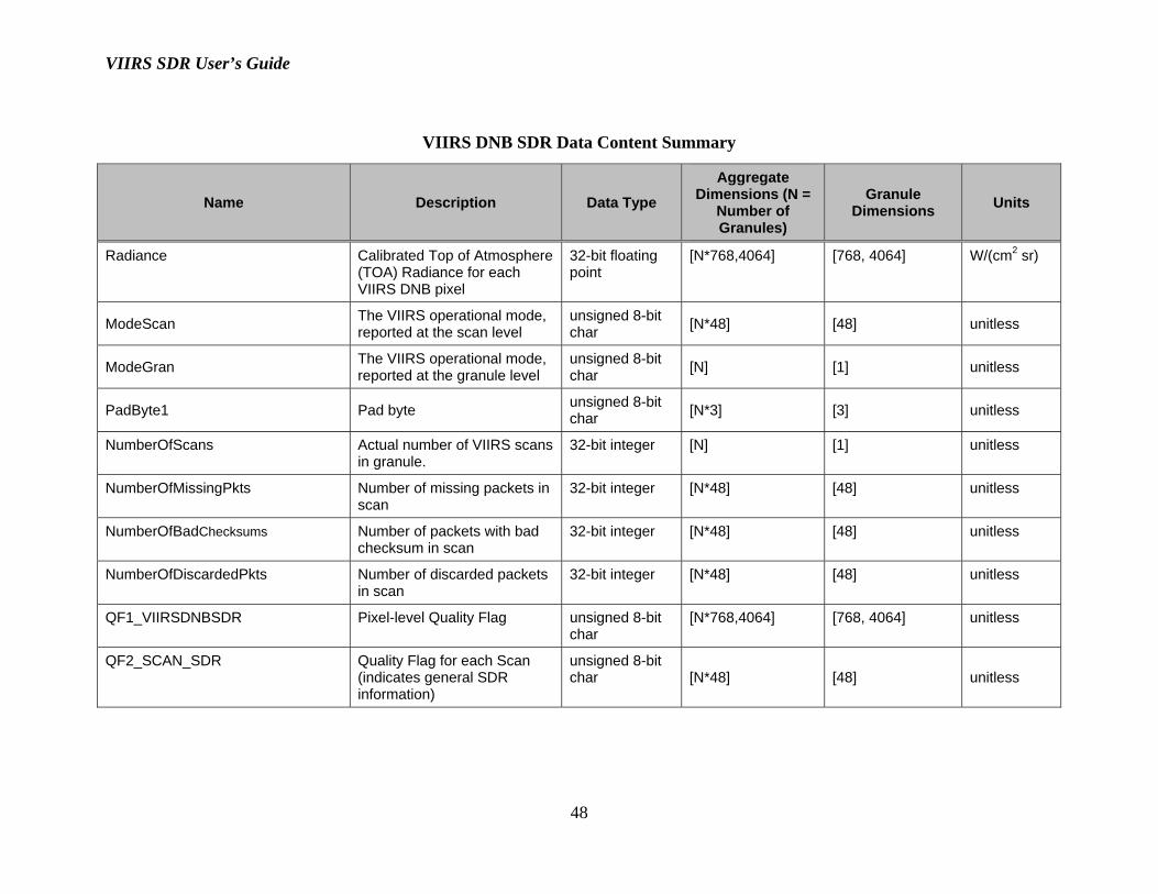
VIIRS DNB SDRs The Visible/Infrared Imaging/Radiometer Suite (VIIRS) collects visible/infrared imagery and radiometric data. The Day-night Band (DNB) is described in this section. The VIIRS DNB measures radiance over a panchromatic band at wavelengths between 500 nm and 900 nm. The VIIRS DNB SDR HDF5 data array structures are summarized below, followed by presentation of the UML diagram for this band.
VIIRS SDR User’s Guide
48
VIIRS DNB SDR Data Content Summary
Name Description Data Type Aggregate
Dimensions (N = Number of Granules)
Granule Dimensions Units
Radiance Calibrated Top of Atmosphere (TOA) Radiance for each VIIRS DNB pixel
32-bit floating point
[N*768,4064] [768, 4064] W/(cm2 sr)
ModeScan The VIIRS operational mode, reported at the scan level
unsigned 8-bit char [N*48] [48] unitless
ModeGran The VIIRS operational mode, reported at the granule level
unsigned 8-bit char [N] [1] unitless
PadByte1 Pad byte unsigned 8-bit char [N*3] [3] unitless
NumberOfScans Actual number of VIIRS scans in granule.
32-bit integer [N] [1] unitless
NumberOfMissingPkts Number of missing packets in scan
32-bit integer [N*48] [48] unitless
NumberOfBadChecksums Number of packets with bad checksum in scan
32-bit integer [N*48] [48] unitless
NumberOfDiscardedPkts Number of discarded packets in scan
32-bit integer [N*48] [48] unitless
QF1_VIIRSDNBSDR Pixel-level Quality Flag unsigned 8-bit char
[N*768,4064] [768, 4064] unitless
QF2_SCAN_SDR Quality Flag for each Scan (indicates general SDR information)
unsigned 8-bit char [N*48] [48] unitless

VIIRS SDR User’s Guide
49
Name Description Data Type Aggregate
Dimensions (N = Number of Granules)
Granule Dimensions Units
QF3_SCAN_RDR Quality Flag for each Scan (indicates general RDR information)
unsigned 8-bit char [N*48] [48] unitless
VIIRS DNB Geolocation Content Summary
The VIIRS DNB SDR geolocation arrays structures are summarized below.
VIIRS DNB SDR Geolocation Content Summary
Name Description Data Type Aggregate Dimensions
Granule Dimensions Units
StartTime Starting Time of each scan in IET (1/1/1958)
64-bit integer [N*48] [48] microsecond
MidTime Mid-Time of each scan in IET (1/1/1958)
64-bit integer [N*48] [48] microsecond
Latitude Latitude of each pixel (positive North)
32-bit floating point
[N*768, 4064] [768, 4064] degree
Longitude Longitude of each pixel (positive East)
32-bit floating point
[N*768, 4064] [768, 4064] degree
SolarZenithAngle Zenith angle of sun at each pixel position
32-bit floating point
[N*768, 4064] [768, 4064] degree
SolarAzimuthAngle Azimuth angle of sun (measured clockwise positive from North) at each pixel position
32-bit floating point
[N*768, 4064] [768, 4064] degree

VIIRS SDR User’s Guide
50
Name Description Data Type Aggregate Dimensions
Granule Dimensions Units
SatelliteZenithAngle Zenith angle to Satellite at each pixel position
32-bit floating point
[N*768, 4064] [768, 4064] degree
SatelliteAzimuthAngle Azimuth angle (measured clockwise positive from North) to Satellite at each pixel position
32-bit floating point
[N*768, 4064] [768, 4064] degree
LunarZenithAngle Zenith angle of moon at each pixel position
32-bit floating point
[N*768, 4064] [768, 4064] degree
LunarAzimuthAngle Azimuth angle of moon (measured clockwise positive from North) at each pixel position
32-bit floating point
[N*768, 4064] [768, 4064] degree
Height Ellipsoid-Geoid separation 32-bit floating point
[N*768, 4064] [768, 4064] meter
SatelliteRange Line of sight distance from the ellipsoid intersection to the satellite
32-bit floating point
[N*768, 4064] [768, 4064] meter
SCPosition Spacecraft position in ECR Coordinates (X, Y, Z) at the mid-time of scan
32-bit floating point
[N*48,3] [48, 3] meter
SCVelocity Spacecraft velocity in ECR Coordinates (dx/dt, dy/dt, dz/dt) at the mid-time of scan
32-bit floating point
[N*48,3] [48, 3] m/s
SCAttitude Spacecraft attitude with respect to Geodetic Reference Frame Coordinates (roll, pitch, yaw)
32-bit floating point
[N*48, 3] [48, 3] arcsecond
SCSolarZenithAngle
The angle from the normal vector of the Solar Diffuser surface (z-axis of the solar diffuser frame) to the solar vector
32-bit floating point [N*48] [48] degree

VIIRS SDR User’s Guide
51
Name Description Data Type Aggregate Dimensions
Granule Dimensions Units
SCSolarAzimuthAngle
The angle from the Solar Diffuser reference frame x-axis to the projection of the solar vector onto the solar diffuser surface (x-y plane), measured counterclockwise (observer looking toward the SD surface)
32-bit floating point [N*48] [48] degree
MoonPhaseAngle Angle between ray vector to moon from earth and ray vector of satellite to earth
32-bit floating point
[N] [1] degree
MoonIllumFraction Fraction of the moon illuminated (expressed as percent)
32-bit floating point
[N] [1] unitless
ModeScan The VIIRS operational mode, reported at the scan level
unsigned 8-bit char
[N*48] [48] unitless
ModeGran The VIIRS operational mode, reported at the granule level
unsigned 8-bit char
[N] [1] unitless
PadByte1 Pad byte unsigned 8-bit char [N*3] [3] unitless
NumberOfScans Actual number of VIIRS scans that were used to create this granule
32-bit integer [N] [1] unitless
QF1_SCAN_VIIRSSDRGEO Scan-level quality flag unsigned 8-bit char
[N*48] [48] unitless
QF2_VIIRSSDRGEO Pixel-level quality flag unsigned 8-bit char
[N*768, 4064] [768,4064] unitless

VIIRS SDR User’s Guide
52
APPENDIX B: Data Quality Flags
Data Product or Flag Descriptions
Bits in Granule
(Assumes 12 scans
per Granule)
'M' indicates
a metadata
flag
Bits in
Cell Values Granule
QFs Cell DQN Comments
VIIRS SDR SDR Flags common to all Bands
Summary VIIRS SDR Quality
Percent of Good Quality pixels in Granule
8 (M) 0-100% X Yes Set if any detailed flags are set (below); one/scan
Scan Quality Exclusion
Indicates the number of scans that SDR product could not be produced (including partial scans)
5 0-16 X Yes # of scans that SDR product could not be produced (including partial scans)
Moon in keep-out-box
Indicated that the moon has corrupted the space view. 1 bit/band/scan.
352
Moon in Space View Moon not in Space View
X No 1 bit/per scan
Bad Detector - M-Bands
M-bands - 1 bits/detector/granule (16 detectors).
16 Good Bad X No M-bands - 1 byte/scan
(16 detectors)

VIIRS SDR User’s Guide
53
Bad Detector - I-Bands
I-bands - 1 bits/detector/granule (32 detectors).
32 Good Bad X No I-bands - 2 bytes/scan
(32 detectors)
Ham side
Flag indicates which side of the HAM was valid for each VIIRS scan
16 A B X No
1 bit/per scan. This flag was added here as but was previously in the VIIRS SDR product description.
VIIRS 375m (Imagery) Scan-line quality flag
This contains quality flags for every detector for every band. A value of 0 indicates good quality for the scan line. A value of >0 indicates reduced quality. The actual value is determined by the combined number of steps required to find a replacement for thermistor or calibration source data.
128 0-255 8 bits/scan No

VIIRS SDR User’s Guide
54
VIIRS 750m (Moderate) Scan-line quality flag
This contains quality flags for every detector for every band. A value of 0 indicates good quality for the scan line. A value of >0 indicates reduced quality. The actual value is determined by the combined number of steps required to find a replacement for thermistor or calibration source data.
128 0-255 8 bits/scan No
SDR Quality
Indicates calibration quality due to bad space view offsets, OBC view offsets, etc or use of a previous calibration view.
2
Good Poor No Calibration
X No
Saturated Pixel Indicates the level of pixel saturation 2
None Saturated Some Saturated All Saturated
X No
Missing data
Data required for calibration processing is not available for processing
2
1) All data present 2) EV RDR data missing 3) Cal data (SV, CV, SD, etc)
X No

VIIRS SDR User’s Guide
55
missing or bad 4) Thermistor data missing or bad
Out of Range
Calibrated pixel value outside of LUT threshold limits
2
1) All data within range 2) Radiance out of range 3) Reflectance or EBBT out of range 4) Both Radiance and Reflectance or EBBT out of range
X No
Out of Range - DNB
Calibrated pixel value outside of LUT threshold limits
1
1) All data within range 2) Radiance out of range
X No Updated DNB out-of-range flag. Matches DFCB - D34862-03 Rev B
Verified RDR Flags (passed through to all SDRs)
RDR Pixel/Sample Quality Exclusion
Indication that the checksums that are imbedded in the instrument's science data did
96
Number of zones per scan*number of
No

VIIRS SDR User’s Guide
56
not verify during ground processing
scans
VIIRS RDR Scan Quality
1) Scan Data Presence 2) Missing packets in Scan 3) Packets with bad Checksum in Scan 4) Discarded packets in Scan
1552
1) Some Valid Data/No valid Data 2) Number is missing packets (32 bits) 3) Number of packets with bad Checksum (32 bits) 4) Number of discarded packets (32 bits)
int32/[nscans x 4]
No Scan Data Quality
Geolocation
Automatic Quality Flag
Granule level quality flag indicating whether or not the retrieval successful or not
1
Retrieval sucessful Retrieval not sucessful
X No Set to 0 if granule level quality assurance metadata retrieval successful otherwise set to 1
QA Percent Missing Data
8 bit scaled integer containing the percentage of missing data. Internally, code keeps # of pixels in granule and number of pixels with missing data
8 0-100% X No
8 bit scaled integer containing the percentage of missing data. Internally, code keeps # of pixels in granule and number of pixels with missing data (I.e., insufficient data for geolocation), both as integers. The quotient is computed in one of the write routines and output to the

VIIRS SDR User’s Guide
57
(I.e., insufficient data for geolocation), both as integers. The quotient is computed in one of the write routines and output to the metadata.
metadata.
QA Percent Out Of Bounds Data
8 bit scaled integer containing the percentage of out of bounds data. Internally, code keeps # of pixels in granule and number of out of bounds pixels (I.e., pixels than can not be geolocated), both as integers. The quotient is computed in one of the write routines and output to the metadata.
8 0-100% X No
8 bit scaled integer containing the percentage of out of bounds data. Internally, code keeps # of pixels in granule and number of out of bounds pixels (I.e., pixels than can not be geolocated), both as integers. The quotient is computed in one of the write routines and output to the metadata.
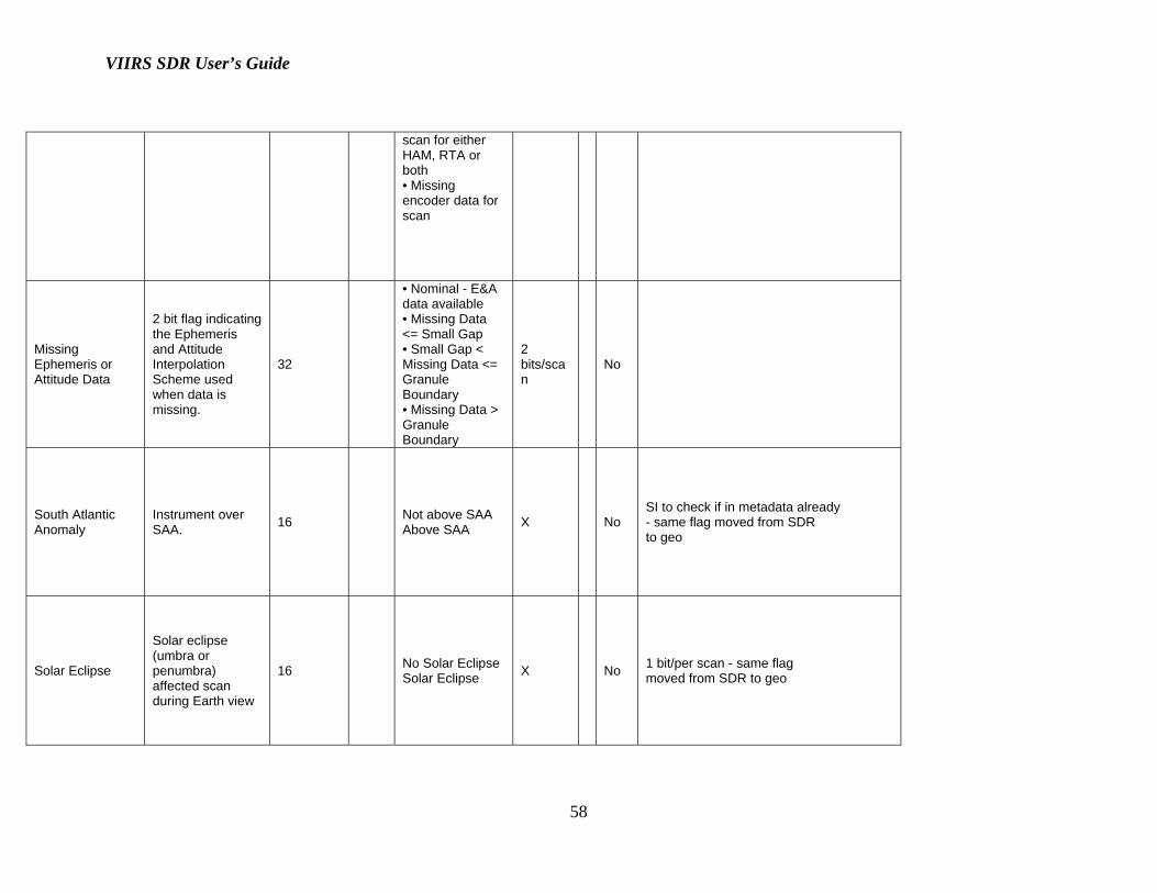
HAM/RTA Encoder
Indicates the quality of the HAM and RTA encoder timestamps
32
• Nominal – All encoder data valid • Bad – All encoder data is bad for entire scan for HAM, RTA or both • Degraded – Some timestamps are invalid within
X No
HAM_impulse_flag, SCI_ ABNORM, & SCI_STATE: Note: SCI_ABNORM, & SCI_STATE removed for version 2.0
VIIRS SDR User’s Guide
58
scan for either HAM, RTA or both • Missing encoder data for scan
Missing Ephemeris or Attitude Data
2 bit flag indicating the Ephemeris and Attitude Interpolation Scheme used when data is missing.
32
• Nominal - E&A data available • Missing Data <= Small Gap • Small Gap < Missing Data <= Granule Boundary • Missing Data > Granule Boundary
2 bits/scan
No
South Atlantic Anomaly
Instrument over SAA. 16 Not above SAA
Above SAA X No SI to check if in metadata already - same flag moved from SDR to geo
Solar Eclipse
Solar eclipse (umbra or penumbra) affected scan during Earth view
16 No Solar EclipseSolar Eclipse X No 1 bit/per scan - same flag
moved from SDR to geo

VIIRS SDR User’s Guide
59
Lunar Eclipse Lunar eclipse during Earth view scan
16 No Lunar EclipseLunar Eclipse X No 1 bit/per scan - same flag moved
from SDR to geo - DNB only
Invalid Input Data
Indicates that any of the SC ephemeris or attitude data is invalid or the encoder data is invalid
1 Valid Invalid X No
Bad Pointing
Indicates that the sensor LOS does not intersect the geoid, is near the limb or has invalid sensor angles
1 Good Pointing Bad Pointing X No
Bad Terrain
Indicates that the algorithm could not obtain a valid terrain value
1 Good Terrain Bad Terrain X No

VIIRS SDR User’s Guide
60
Invalid Solar angles
Indicates that the solar angles are invalid.
1 Valid angles Invalid angles X No