Embed Size (px)
Citation preview

UNIT- 5
RESONANT CIRCUITS
Q.1)Define quality factor and bandwidth. Also establish the relationship between them in a series
resonance circuit. JUNE 2014, JUNE 2013, JUNE 2015
Ans.: Quality factor : The Q factor of series resonant circuit is nothing but the Q factor of inductor or
capacitor in series resonant circuit at resonant frequency. At resonance the reactance of inductor is same
as that of capacitor magnitude wise. Hence the energy stored by both the elements would be same. Q
factor of series resonant circuit is denoted by Q0. At resonance, Q0 is given by
Thus above expression gives quality factor of series resonant circuit in terms of resonant circuit
elements.
Band width: Band width of series RLC circuit is defined as the width of resonant curve upto frequency
at which the power in the circuit is half of its maximum value. At frequency of resonance, the maximum
current I0 is given by,
This current is maximum as impedance is minimum at resonance. Hence at resonant frequency, power
in the circuit is maximum and given by, P0 = Pmax = (I0)2 .R Now, half of maximum power is given
by,
So at the frequencies, where power in the circuit is half of its maximum value, current becomes 1/√ 2
times or 0.707 times of its maximum value. The frequencies at which power in the circuit is half of its
maximum value are called half power frequencies. The band width of series resonant circuit is as shown
in Fig.

At resonant frequency, power in circuit is given by, P0 = Pmax = (I0)2 .R At frequency, power
in circuit is half and it is given by, P’ = ½ (I0)2 . R and Similarly at frequency f2 power in circuit is half
and is given by, P’ = ½ (I0)2 . R Thus, f1 is called lower half-power frequency and f2 is called upper
half power frequency. According to definition of bandwidth, the bandwidth of series RLC circuit is
given by, Bandwidth = (f2-f1)Hz
The half-power frequencies are also referred as 3 dB frequencies or 3 dB points because the
power at these frequencies is 3dB less than that at the resonance. Let us now determine these 3dB
frequencies and evaluate bandwidth and selectively for series resonant circuit.
Relationship between Q factor and Bandwidth The current in a series RLC circuit is given by
equation,
Thus, from above equation it is clear that at half-power frequencies f1 and f2, the reactive part of
impedance of series RLC circuit is equal to resistive part of impedance. We can write,

Selectivity of a resonant circuit is defined as the ability of a circuit to discriminate or distinguish
between desired and undesired frequencies. Selectivity is also defined as the ratio of resonant frequency
to the bandwidth of resonant circuit.
Thus, selectivity of series resonant circuit is directly proportional to the quality factor of circuit at
resonant frequency. So selectivity of the resonant circuit depends on Q0. If Q0 is very high, amplitude
response curve becomes sharper effectively decreasing bandwidth. If Q0 is very small, bandwidth
increases making amplitude response curve flater.
Thus, bandwidth of series resonant circuit is inversely proportional to quality factor Q0 of the circuit at
resonant frequency.
Q.2) A series resonance circuit with R = 17Ω. L = 0.1H and C= 50µF has an applied voltage V=50
0ے ° with a variable frequency. Find the resonant frequency, the value of frequency at which
maximum voltage occurs across inductor and the value of frequency at which maximum voltage
occurs across capacitor. JUNE 2015, JAN.2014

Q.3) Show that resonant frequency of series resonance circuit is equal to the geometric mean of two
half power frequencies. JAN.2015

Thus, f1 is called lower half-power frequency and f2 is called upper half power frequency. According to
definition of bandwidth, the bandwidth of series RCL circuit is given by, Bandwidth = (f2-f1) Hz The
half-power frequencies are also referred as 3 dB frequencies or 3 dB points because the power at these
frequencies is 3 dB less than that at the resonance. Let us now determine these 3 dB frequencies and
evaluate bandwidth and selectively for series resonant circuit.
Thus, from above equation it is clear that at half-power frequencies f1 and f2, the reactive part of
impedance of series RCL circuit is equal is equal to resistive part of impedance. Above equation is

quadratic in ω, which gives two values of ω as ω1 and ω2 whose half-power frequencies (i.e. f1 and f2)
are as shown in Fig. 20. We can write,
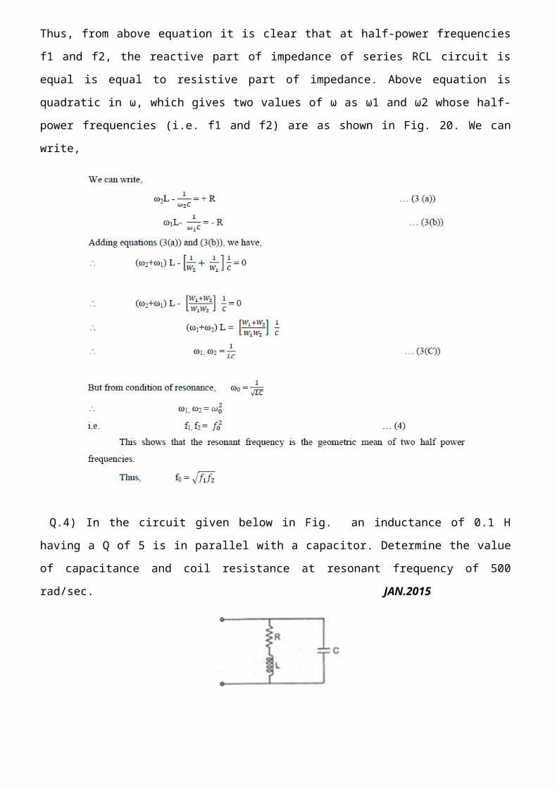
Q.4) In the circuit given below in Fig. an inductance of 0.1 H having a Q of 5 is in parallel with a
capacitor. Determine the value of capacitance and coil resistance at resonant frequency of 500 rad/sec.
JAN.2015
Ans.: The given circuit is practical parallel resonant circuit. The antiresonant frequency in terms of the
Q-factor is given by
Q.5) Determine the R-L-C parallel circuit parameters whose response curve is as shown fig. What are
the new values of ωr and band width if c is increased 4 times? JAN.2013

Q.6) In the case of a series resonant circuit with frequency variation, obtain expressions for
i) ωC at which maximum voltage occurs across C
ii) ωL at which maximum voltage occurs across L and show that ω1>ωC JAN.2014


Q.7) Derive the expression for the resonant frequency of the circuit shown in Fig. Also show that the
circuit will resonate at all frequencies if RL = RC = √ L/C JAN.2014, JUNE 2015
The two branches connected in parallel will produce resonance when the resultant current through
combination, i.e. I, is in phase with voltage V as shown in Fig. 10(b). The condition of parallel
resonance is that the impedance of the parallel combination is purely resistive. The condition for
resonance can be derived as follows : The admittance of branch containing L and RL is given by


where far is frequency of resonance. The values of RL and RC are in general vary small. RL is ohmic
resistance of coil or inductor and RC is leakage and dielectric loss resistance of capacitor. Both these are
unavoidable but actually both are very small. If the two resistances are selected such that then the
imaginary term in the equation (1) becomes zero. Thus the reactance is zero. For all frequencies, the
circuit is under unity power factor condition. With the above mentioned condition, antiresonance is
possible at all the frequencies in the circuit.