Embed Size (px)
Citation preview
RF Communication:
A. Introduction:
There are two normal modulations for cubesat design: GMSK and QPSK
(1) GMSK Minimum Shift Keying (MSK) modulation is a constant envelope signal with continuous phase that results from modulating the instantaneous frequency with rectangular pulses. MSK is considered to be a special case of Offset QPSK (OQPSK) with half sinusoidal pulse weighting rather than rectangular. MSK presents lower side lobes than QPSK and OQPSK. The Gaussian Minimum Shift Keying (GMSK) modulation is a modified version of the MSK modulation where the phase is further filtered through a Gaussian filter to smooth the transitions from one point to the next in the constellation.[1]The Gaussian filter equation is:
(2) QPSK: Sometimes this is known as quadriphase PSK, 4-PSK, or 4-QAM. (Although the
root concepts of QPSK and 4-QAM are different, the resulting modulated radio waves are exactly the same.) QPSK uses four points on the constellation diagram, equispaced around a circle. With four phases, QPSK can encode two bits per symbol, shown in the diagram with Gray coding to minimize the bit error rate (BER). [2]
In this project, we will apply both modulations as our design. The stock UTRX Half-Duplex UHF transceiver from Clyde-Space using GMSK modulation, and a high speed S-Band transmitter from Clyde-Space using QPSK modulation. In the following, it will show the two design and the benefits of these two systems.
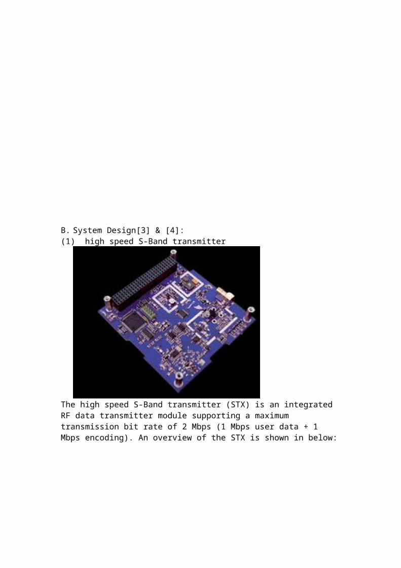
B. System Design[3] & [4]:(1) high speed S-Band transmitter
The high speed S-Band transmitter (STX) is an integrated RF data transmitter module supporting a maximum transmission bit rate of 2 Mbps (1 Mbps user data + 1 Mbps encoding). An overview of the STX is shown in below:
The STX implements QPSK or OQPSK modulation with Intelsat IESS-308 based encodingwhich ensures compatibility with low cost commercial ground segment receivers. The STX will be configured through commands sent via digital code (I2C) on chip. The commands set parameters such as output power, carrier frequency, and transmission data rate. Moreover, the telemetry data would also be organized and calculated via the processing, which is shown in below:
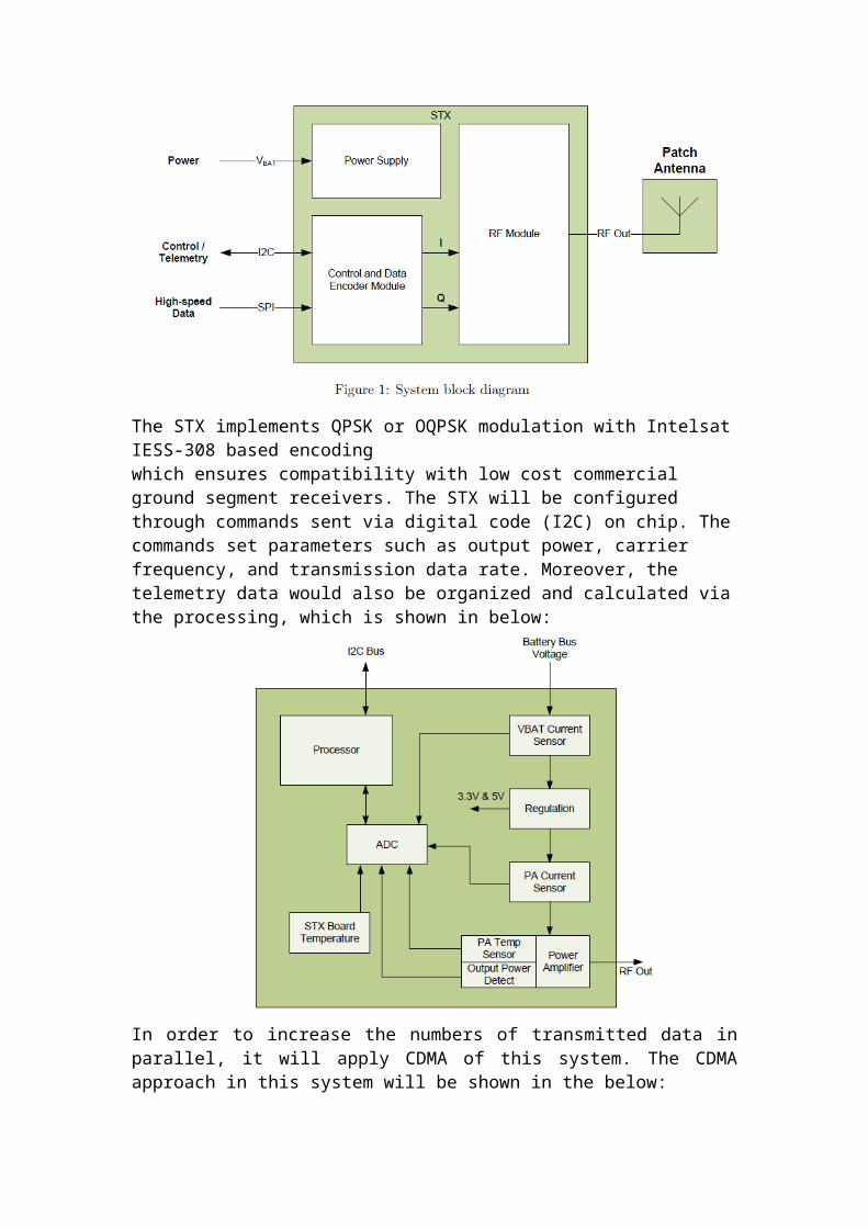
In order to increase the numbers of transmitted data in parallel, it will apply CDMA of this system. The CDMA approach in this system will be shown in the below:
In the diagram, PSK modulation can be QPSK or BPSK, we choose QPSK in here which can improve the data rate and can be allocated on the STX. Moreover, for CubSat i, where i = 1, . . . .M, and M is number of CubeSats, data is encoded with rate 1/2 AR4JA LDPC CCSDS standard code.
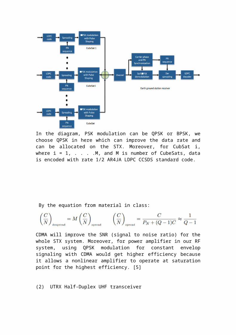
By the equation from material in class:
CDMA will improve the SNR (signal to noise ratio) for the whole STX system. Moreover, for power amplifier in our RF system, using QPSK modulation for constant envelop signaling with CDMA would get higher efficiency because it allows a nonlinear amplifier to operate at saturation point for the highest efficiency. [5]
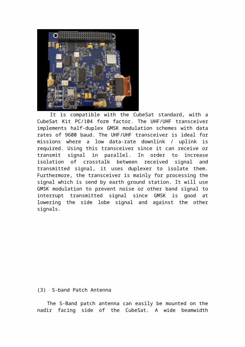
(2) UTRX Half-Duplex UHF transceiver
It is compatible with the CubeSat standard, with a CubeSat Kit PC/104 form factor. The UHF/UHF transceiver implements half-duplex GMSK modulation schemes with data rates of 9600 baud. The UHF/UHF transceiver is ideal for missions where a low data-rate downlink / uplink is required. Using this transceiver since it can receive or transmit signal in parallel. In order to increase isolation of crosstalk between received signal and transmitted signal, it uses duplexer to isolate them. Furthermore, the transceiver is mainly for processing the signal which is send by earth ground station. It will use GMSK modulation to prevent noise or other band signal to interrupt transmitted signal since GMSK is good at lowering the side lobe signal and against the other signals.
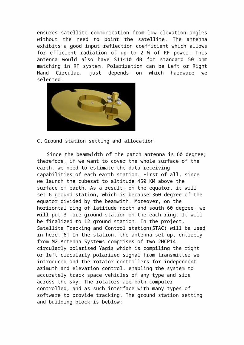
(3) S-band Patch Antenna
The S-Band patch antenna can easily be mounted on the nadir facing side of the CubeSat. A wide beamwidth ensures satellite communication from low elevation angles without the need to point the satellite. The antenna exhibits a good input reflection coefficient which allows for efficient radiation of up to 2 W of RF power. This antenna would also have S11<10 dB for standard 50 ohm matching in RF system. Polarization can be Left or Right Hand Circular, just depends on which hardware we selected.
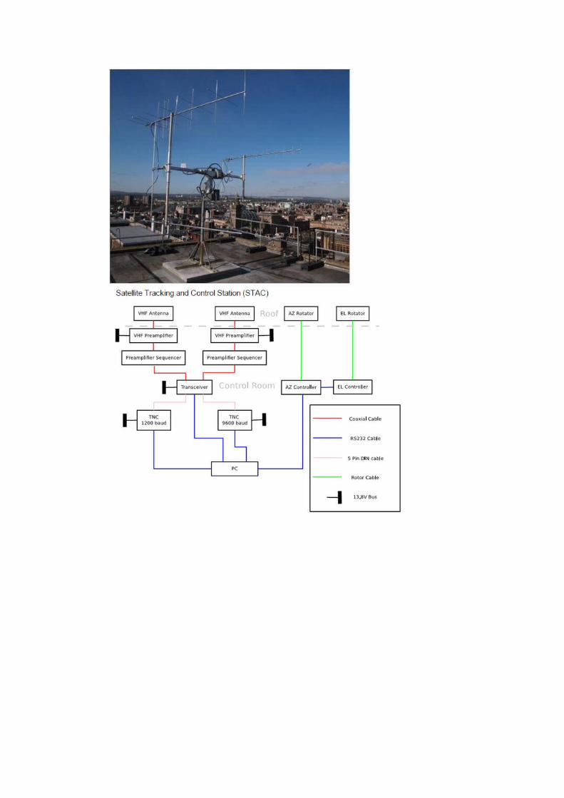
C. Ground station setting and allocation
Since the beamwidth of the patch antenna is 60 degree; therefore, if we want to cover the whole surface of the earth, we need to estimate the data receiving capabilities of each earth station. First of all, since we launch the cubesat to altitude 450 KM above the surface of earth. As a result, on the equator, it will set 6 ground station, which is because 360 degree of the equator divided by the beamwith. Moreover, on the horizontal ring of latitude north and south 60 degree, we will put 3 more ground station on the each ring. It will be finalized to 12 ground station. In the project, Satellite Tracking and Control station(STAC) will be used in here.[6] In the station, the antenna set up, entirely from M2 Antenna Systems comprises of two 2MCP14 circularly polarised Yagis which is compiling the right or left circularly polarized signal from transmitter we introduced and the rotator controllers for independent azimuth and elevation control, enabling the system to accurately track space vehicles of any type and size across the sky. The rotators are both computer controlled, and as such interface with many types of software to provide tracking. The ground station setting and building block is beblow:
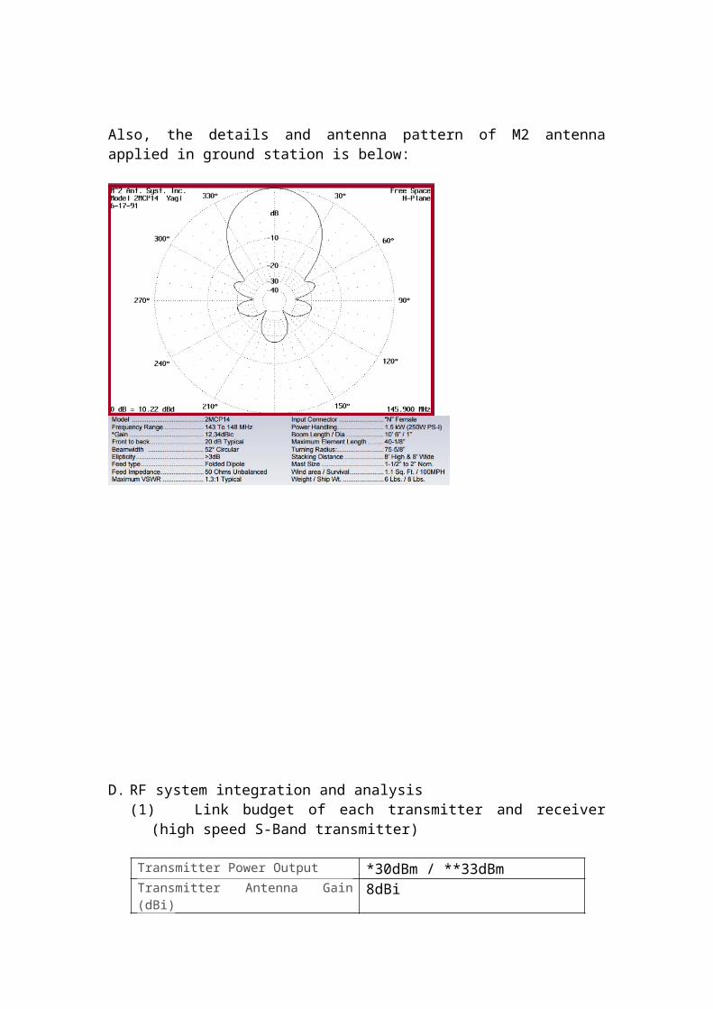
Also, the details and antenna pattern of M2 antenna applied in ground station is below:
D. RF system integration and analysis(1) Link budget of each transmitter and receiver (high speed S-Band transmitter)
Transmitter Power Output *30dBm / **33dBmTransmitter Antenna Gain (dBi) 8dBiMiscellaneous Loss (dB) -113.5dBReceiver Antenna Gain (dBi) 12.3dBiReceiver Loss (dB) Within 1dB
* high speed S-Band transmitter ** UTRX Half-Duplex UHF transceiver
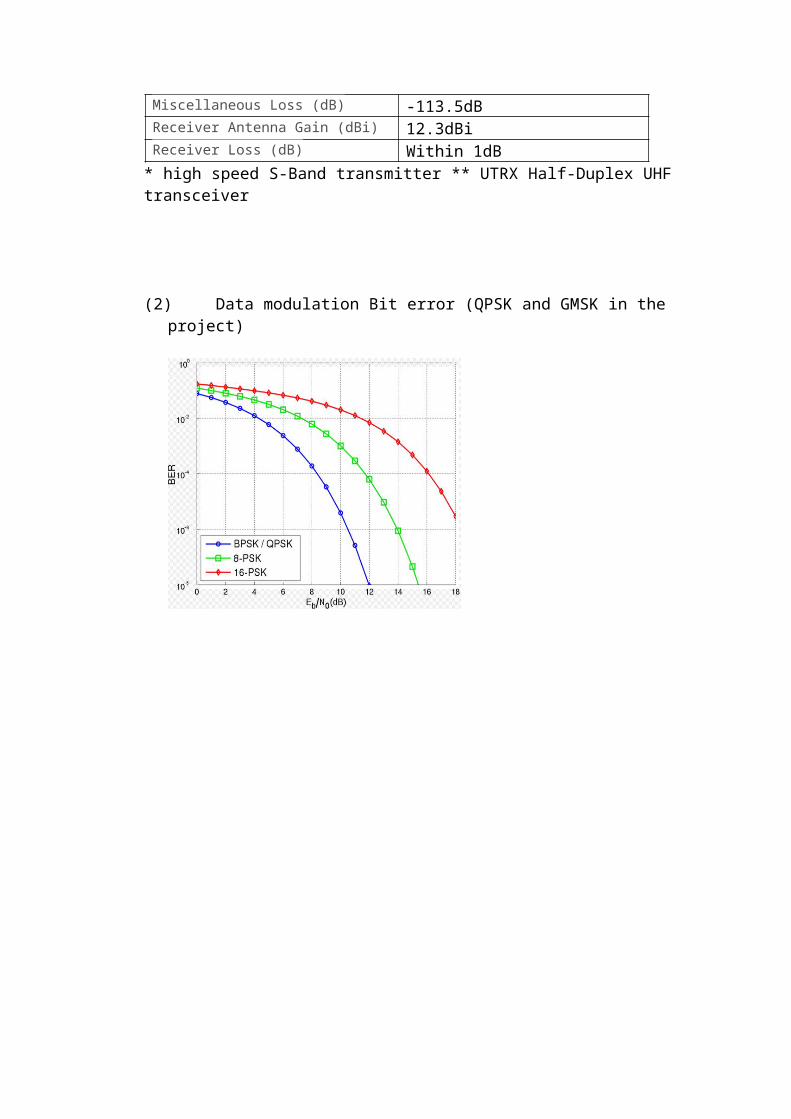
(2) Data modulation Bit error (QPSK and GMSK in the project)
Based on the plots above, GMSK and QPSK behave high quality BER to send signals. And CDMA would help us to allocate more data and cause coding gain to improve SNR. For our case, the 2Mbits/ sec signal can be improve 19dB overall, assuming we have 80 cubesat users.
E. Data organizationHere is signal transmission via RF system:Surface area of Earth: 510,000,000 sqkm Area of picture (assuming .01x.01(km) pixel): 2882.9 sqkmPictures for the surface of Earth: 176,906Data for that many pictures (3.8MB per picture): 672,243 MB or 5,377,942 MbitsDownload time at 2 Mb/s : 2,688,971sIf CDMA (the coding number is 80) is allocated on the RF system to allow parallel transmissions, the total time can be reduced like 2,688,971 / 80 = 33612.13 seconds = 560.2 minutes = 9.33 hours for the entire system to transmit an entire set of Earth surface image data.
Since the satellites are all on the same orbital track, they are constantly sequentially taking photos as they pass over the light side of the planet. On an individual basis, each satellite will collect 869 MB of image data as it passes over the illuminated side of the planet:
Circumference of Earth = 40086722.26 metersCubeSat only images half circumference = 20043361.13 meters“Height” of image @ 10 meter/pixel = 43840 meters# images per orbit assuming 76 satellites = 228.6 imagesTotal size of data per orbit per satellite @ avg. 3.8 MB/image = 868.67 MB2 Megabits/sec transmit rate= 0.25 Megabytes/sec => ~1350 Megabytes per 90 minute orbit.
If a satellite is transmitting for at least 64% (868.67/1350) of its orbital period, it will be capable of transmitting its full orbit’s worth of image data within that time frame.
[1] http://www.navipedia.net/index.php/Gaussian_Minimum_Shift_Keying_(GMSK)[2] https://en.wikipedia.org/wiki/Phase-shift_keying#Quadrature_phase-shift_keying_.28QPSK.29[3] http://www.clyde-space.com/cubesat_shop/communication_systems/301_cubesat-s-band-transmitter[4] http://www.clyde-space.com/cubesat_shop/communication_systems/350_utrx-half-duplex-uhf-transceiver[5] http://ieeexplore.ieee.org/stamp/stamp.jsp?tp=&arnumber=6836341[6] http://www.clyde-space.com/cubesat_shop/ground_stations/343_satellite-tracking-and-control-station-stac


![[XLS] · Web viewRF Products, System LSI business, Semiconductor, Samsung Electronics, Suwon P.O.Box 105, Kyunggi do, Korea. Department of Electrical Engineering and Computer Science,](https://img.pdfslide.us/doc/110x75/5ad1b0be7f8b9a0f198b9f81/xls-viewrf-products-system-lsi-business-semiconductor-samsung-electronics.jpg)