Embed Size (px)
Citation preview

Making Dice in
Autodesk Inventor
2015
What are Dice?

A traditional die is a cube, often with corners slightly rounded. Die are marked on each of its six faces with a different number of circular patches or pits called pips. All of these pips have the same appearance within a set of dice, and are sized for ease of recognizing the pattern formed by the pips on the face. The design as a whole is aimed at each die providing one randomly determined integer, in the range from one to six, with each of those values being equally likely.
Step 1: Drawing the cube
Open Autodesk inventor 2015 program by clicking on the windows button on the bottom left of your desk top. Click on the “All Programs” tab and you will find the program in the Autodesk folder or double click on the Autodesk Inventor icon on your desktop.
Select “NEW” in the upper left corner of the Autodesk Inventor window.
Select the “STANDARD .ITP” option in the second window and the select “CREATE”
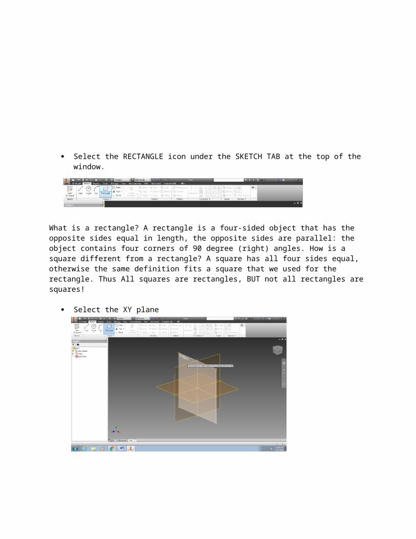
Select the RECTANGLE icon under the SKETCH TAB at the top of the window.
What is a rectangle? A rectangle is a four-sided object that has the opposite sides equal in length, the opposite sides are parallel: the object contains four corners of 90 degree (right) angles. How is a square different from a rectangle? A square has all four sides equal, otherwise the same definition fits a square that we used for the rectangle. Thus All squares are rectangles, BUT not all rectangles are squares!
Select the XY plane
Draw a rectangle by placing your mouse pointer in the upper left quadrant of the grid and LEFT CLICK your mouse. This will set the initial point of your rectangle. Move your mouse pointer to the lower right quadrant of the grid and LEFT CLICK your mouse. This will set the rectangle on the grid and remove the mouse pointer from the rectangle.
Select the “=” by the constrain portion of the tool bar

Place your mouse pointer over the TOP LINE of the rectangle. It will turn WHITE. Left click and it will turn BLUE. Now select the LEFT LINE of the rectangle. It will also turn WHITE when you put your mouse over it, but it won’t turn blue when you left click on it as the rectangle becomes a square.
Now we must give our SQUARE a DIMENSION (length of each side). Because ALL four sides are equal we only need to dimension one of the sides. Select DIMENSION icon from the CONSTRAINT menu bar.
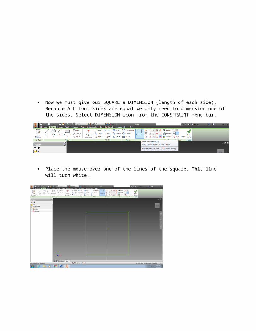
Place the mouse over one of the lines of the square. This line will turn white.
Left click on the line. It will now turn blue. Move your mouse to the left and you will notice dimension lines and a dimension now appears on your screen.
Left click once to set these lines on your grid. Place your mouse pointer over the black dimension line that was set on your grid and left click. An edit dimension box will appear. We will change this dimension to 2.375 (2 3/8”). Type in this measurement and ENTER.

We now need to select the ZOOM ALL icon on the right side of your screen. This will make your square so that you can see the entire object on your screen.
Select FINISH SKETCH from the top tool bar.
Select the 3D MODEL tab at the top of your window.
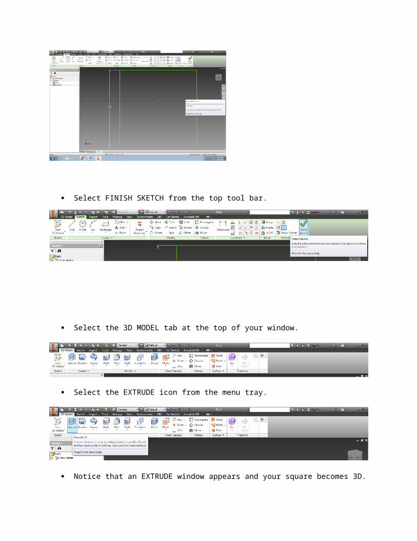
Select the EXTRUDE icon from the menu tray.
Notice that an EXTRUDE window appears and your square becomes 3D.
Type in 2.375 (2 3/8”) in the appropriate box to make our two dimensional square a 3D cube.
In order to see our cube better RIGHT CLICK your mouse and select the HOME VIEW option from the window that appears. Notice that your 3D cube has rotated so that we see an ISOMETRIC view of it.

Notice in the upper right hand corner of your screen that there is a cube that has the 3-views labeled . . . Front, Right, Top!
Now save this drawing to your school drive. Save this drawing as “Dice”
To work on your drawing open it from your drive or folder. This should automatically open the Inventor program. We will now begin to edit this drawing so we can add the holes and discs (pips) to create the dice.
Select the FRONT face of your cube. It will turn blue when selected.

Select the VIEW FACE icon from the transparent icon tray on the right side of your cube drawing. This will change the view so only the FRONT face of your cube is showing.
Select the FRONT surface of your cube. Right click with the mouse and select the NEW SKETCH option.
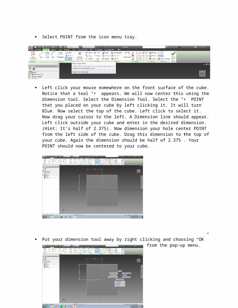
Select POINT from the icon menu tray.

Left click your mouse somewhere on the front surface of the cube. Notice that a teal “+” appears. We will now center this using the dimension tool. Select the Dimension Tool. Select the “+” POINT that you placed on your cube by left clicking it. It will turn Blue. Now select the top of the cube. Left click to select it. Now drag your cursor to the left. A Dimension line should appear. Left click outside your cube and enter in the desired dimension. (Hint: It’s half of 2.375). Now dimension your hole center POINT from the left side of the cube. Drag this dimension to the top of your cube. Again the dimension should be half of 2.375”. Your POINT should now be centered to your cube.
Put your dimension tool away by right clicking and choosing “OK” from the pop-up menu.
Under the 3D MODEL tab Select HOLE from the icon tray menu in the MODIFY section. You will notice that a HOLE window appears. We will need to change two of the sizes and the shape of
the drill point. First we will change the hole depth from 1” to ¼”. Second we will change the hole diameter / width from ¼” to 3/8”. Finally we want to change the drill point to the flat option. When we process this cube later we will use a forstner drill bit to give us this flat profile appearance. Click OK when finished making changes.
We now must do the other surfaces. Things you need to know about dice to move on:o ALL sides OPPOSITE each other will total 7o The side OPPOSITE the surface with a ONE will Equal ______o The side OPPOSITE the surface with a THREE will Equal ______o The side OPPOSITE the surface with a TWO will Equal ______
Let us now make side two of the dice by clicking on the RIGHT SIDE of the cube icon shown in the upper right corner of your window. This will turn the right side of the cube toward us.
“From Sketch” .25”
.375”
Distance

This side of the cube will have TWO holes. Using your knowledge previously learned, let’s create these holes. They should be dimensioned ½” from the side of the cube and ½” from the top / bottom of the cube as pictured below.
Now select the 3D Model tab, the HOLE icon, and keep the same dimensions as we previously made for the first hole.
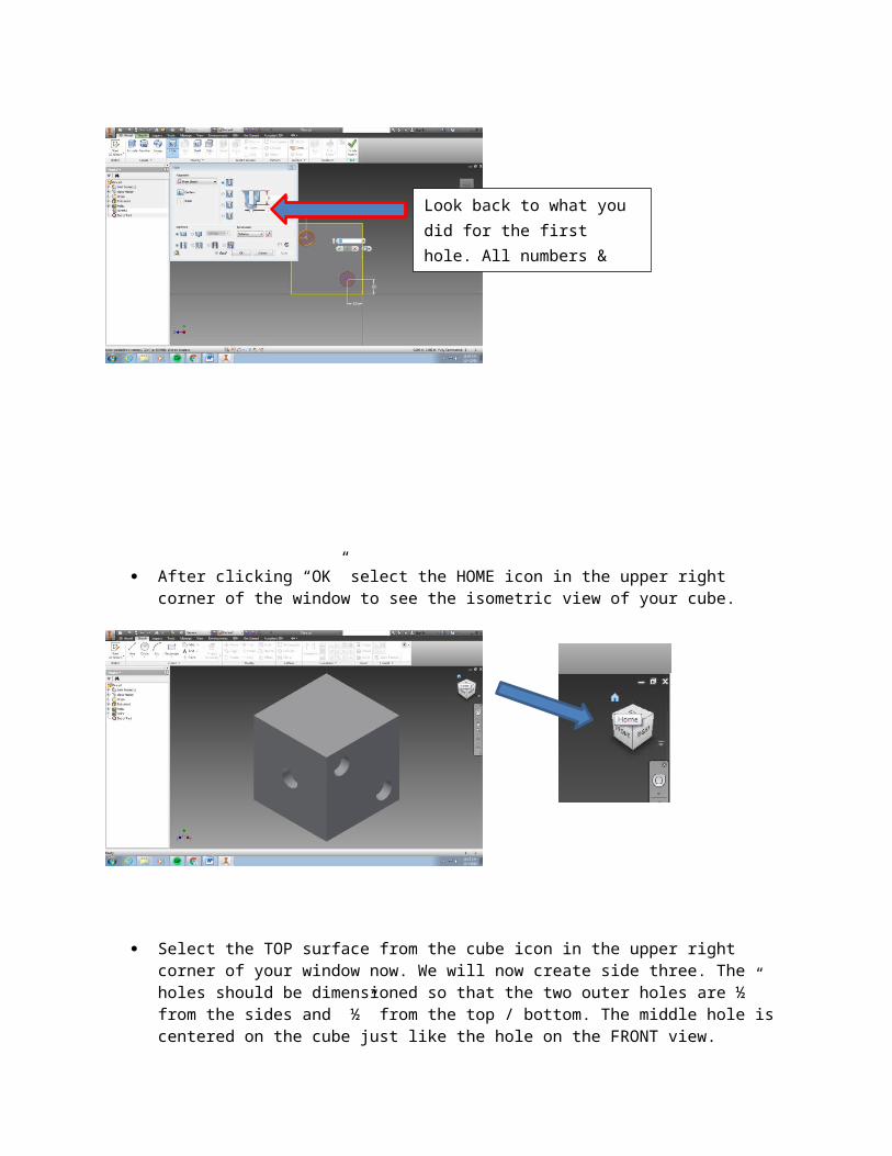
After clicking “OK” select the HOME icon in the upper right corner of the window to see the isometric view of your cube.
Look back to what you did for the first hole. All numbers & parameters are the same.

Select the TOP surface from the cube icon in the upper right corner of your window now. We will now create side three. The holes should be dimensioned so that the two outer holes are ½” from the sides and ½” from the top / bottom. The middle hole is centered on the cube just like the hole on the FRONT view.
Now we must use the FREE ORBIT tool on the right side of your window to turn our cube and create sides four, five, and six. Remember that:
o The side OPPOSITE the one hole surface will have sixo The side OPPOSITE the two hole surface will have fiveo The side OPPOSITE the three hole surface will have four
Rotate your object so that we see side six. It is OPPOSITE side one or the front of you cube.
Dimension side six (BACK) and create the appropriate holes.

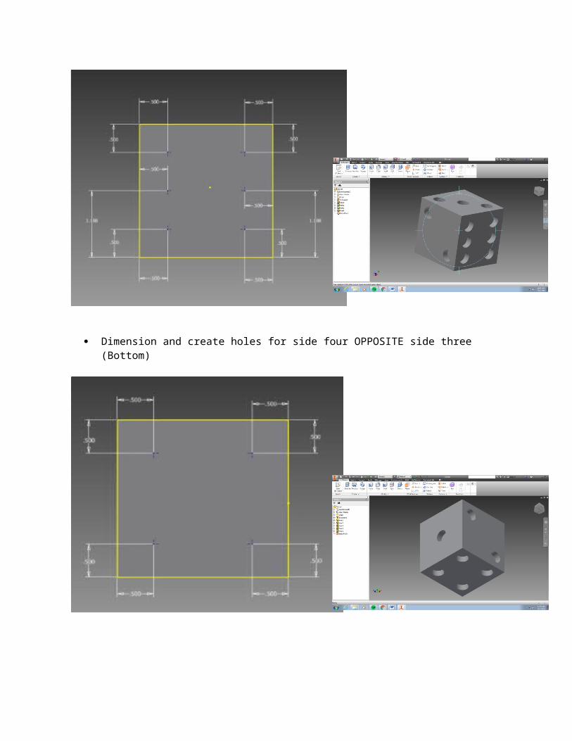
Dimension and create holes for side four OPPOSITE side three (Bottom)
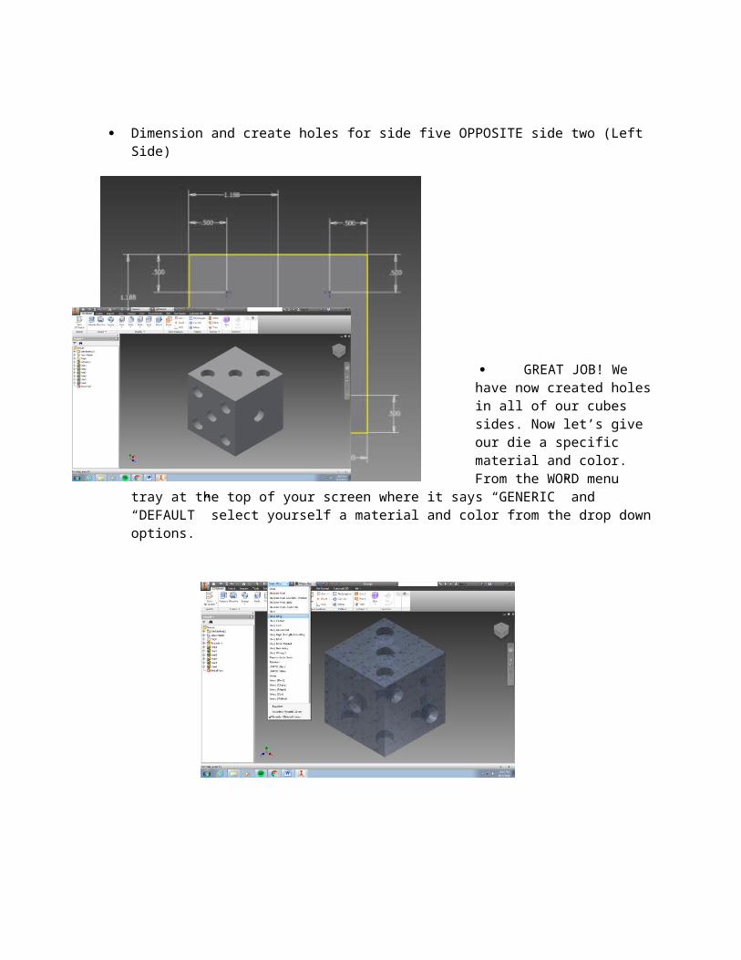
Dimension and create holes for side five OPPOSITE side two (Left Side)

GREAT JOB! We have now created holes in all of our cubes sides. Now let’s give our die a specific material and color. From the WORD menu tray at the top of your screen where it says “GENERIC” and “DEFAULT” select yourself a material and color from the drop down
options.
Now let’s round over the edges of the cube, so that it will roll. Select FILLET from the icon tray menu, under the 3D Model tab.
Change the FILLET Radius to .125 (This equals 1/8”)
Select the front 9 edges and then click the green check mark. You will have to rotate the cube to select the other 3 edges and again clicking the green check mark when finished.
Choose HOME view to see your finished cube.
Make sure you save your hard work to your personal Drive / Tech folder.
So we created our die cube. Is anyone having a hard time actually seeing the holes? Since it’s kind of difficult to see our holes, lets create some discs to fill in the holes so we can see them better. To do this lets open a NEW standard.ipt drawing just like we did to create our cube.
Select CIRCLE under the SKETCH tab from the icon menu tray. Select the XY Plane again. Place a circle anywhere on the grid by left clicking your mouse icon. As you move your mouse the circle will get bigger. Left click your mouse again to draw the circle on your grid as shown below:
Dimension your circle to be .375” (3/8”) in diameter. To dimension our circle we want to select the DIMENSION tool from the icon tray menu at the top of the page. Place your mouse cursor on the circle and left click. Drag the dimension to the side and adjust to read .375 “ (3/8”).
Let’s now extrude our circle to a thickness of .25” (1/4”) using our knowledge that we previously learned while making the cube. Click Finish Sketch then select the EXTRUDE icon under the 3D MODEL tab from the icon tray menu. Finally change the color of the disc to be SNOW.

Save this file to your personal drive technology folder as “PIPS” as this is what the die indentations are called.
Now it’s time to ASSEMBLE the PIPS into our die. In order to do this we must open a new page in Autodesk Inventor 2015. This time we need to select the Standard.iam option in order to do an ASSEMBLY.
We now need to open both our saved DICE and PIPS. We will do this using the place component function from the icon tray menu.

First lets select the die cube that you have already created and saved. Left click on the PLACE icon in the components part of the assembly icon menu. Find your cube file (Mine was saved as “Dice”) and click OPEN.
Your cube will appear on the screen. Place it anywhere and left click once to drop your cube into the assembly drawing. After you left click to drop your die into the drawing a second die will still be showing. To get rid of this second die you will RIGHT CLICK and then choose the OK option to clear the screen. Only one die should be showing if you do this step correctly.

Now we must do the same thing for the “PIPS”. Only this time we need to place 21 “PIPS” in the drawing. One for every hole we have created on the die.
We now need to insert the discs or pips into the die. To do this we need to select constrain from the icon tray menu.
Next we choose INSERT from the place constraint window.

We then select the inside edge of one of the holes in our cube by clicking on it.
Then we choose the top face of one of our discs.

When we click on the top face of the disc, the disc or pip will then be inserted into the cube. Select APPLY. Please know that this action may move the cube or pips. You may have to move or rotate you die cube around to see if the pip was installed properly. If the pip is sticking out of the cube it is because you selected to wrong faces while assembling. Use the UNDO button at the top of the page to undo your action and then redo the process selecting the right faces that you want to assemble together.
Insert all 21 PIPS into their desired locations following the same process learned above. When completed your final die should look like mine pictured below.
YOUR DONE - Great Job! Save this to your Drive as “completed die”. At some point you will show this to the instructor for a grade.