Embed Size (px)
Citation preview

1
OPERATIONS TECHNOLOGY INC.
VideoMic VSA
Technical Manual
QC5000
VIDEO MEASUREMENT AND INSPECTION WORKSTATION.
For: _____________ S/N: _________ Model 713VSA
Version G
January 2008
Operations Technology Inc. P.O. Box 408
Blairstown, NJ 07825 www.optek.net
Phone (908) 362-6200 Fax (908) 362-5966

2
VIDEO MEASUREMENT AND INSPECTION WORKSTATION. .............................................................................. 1
Chapter 1 An Overview ................................................................................................................................................. 5 System Overview ....................................................................................................................................................... 6 System Description .................................................................................................................................................... 6 Camera Head Assembly ............................................................................................................................................ 7 X-Y Split-Axis Transport ............................................................................................................................................. 7 Table Assembly (Granite) .......................................................................................................................................... 7 Electronics Area ......................................................................................................................................................... 7 Control panel: ............................................................................................................................................................. 7 Computer: .................................................................................................................................................................. 7 Part Locations: ........................................................................................................................................................... 8 Software: .................................................................................................................................................................... 8 Documentation for the OPTEK VideoMic................................................................................................................... 8 The Control Panel ...................................................................................................................................................... 9 Power Cutoff Switch Locations: ............................................................................................................................... 10 Operating Principles ................................................................................................................................................. 11
Chapter 2 Getting Started ............................................................................................................................................ 12 OPTEK VideoMic VSA Power On Procedure .......................................................................................................... 13 Homing Sequence, QC5000 .................................................................................................................................... 13 Operational Checkout .............................................................................................................................................. 13 Check system safety and integrity ........................................................................................................................... 13 X and Y Axis ............................................................................................................................................................. 13 Machine Zero ........................................................................................................................................................... 14 Digital Positioner ...................................................................................................................................................... 14 Tooling Fixtures or Hinged Glass Platen. ................................................................................................................ 14 System Cooling ........................................................................................................................................................ 14 The Computer Display ............................................................................................................................................. 14 Screen Window and Video Window ......................................................................................................................... 14 Light Control Sliders ................................................................................................................................................. 15 Quadrant Lighting..................................................................................................................................................... 15 HGP and Lighting ..................................................................................................................................................... 16 General Programming for the VideoMic VSA in QC5000 ........................................................................................ 16 Startup Troubleshooting Checklist ........................................................................................................................... 17 Problems and possible causes ................................................................................................................................ 17 Measuring a part ...................................................................................................................................................... 18 General considerations prior to measuring .............................................................................................................. 18 Preparation for Recording a Part Program .............................................................................................................. 18
Chapter 3 QC5000 Software ....................................................................................................................................... 19 Windows and QC5000 ............................................................................................................................................. 20 Getting around in Windows ...................................................................................................................................... 20 Using the Mouse ...................................................................................................................................................... 20 QC5000 Basics ........................................................................................................................................................ 20 The QC5000 Screen ................................................................................................................................................ 21 The Title Bar ............................................................................................................................................................. 21 The Menu Bar .......................................................................................................................................................... 21 The Status Bar ......................................................................................................................................................... 21 The DRO window (Digital Read Out) ....................................................................................................................... 21 Customization .......................................................................................................................................................... 22 Toolbars in QC5000 ................................................................................................................................................. 23 The Measure Toolbar ............................................................................................................................................... 23 The Probe Toolbar ................................................................................................................................................... 23 The CNC Toolbar ..................................................................................................................................................... 24 The View Toolbar ..................................................................................................................................................... 24 Special Tools ............................................................................................................................................................ 25 The Datum Toolbar .................................................................................................................................................. 25 VED TOOL BAR ....................................................................................................................................................... 26 The QC5000 Menus ................................................................................................................................................. 26 The File Menu .......................................................................................................................................................... 27 Edit Menu ................................................................................................................................................................. 27 View Menu ............................................................................................................................................................... 28
3
Measure Menu ......................................................................................................................................................... 28 Datum Menu ............................................................................................................................................................. 28 Probe Menu .............................................................................................................................................................. 29 Windows Menu ......................................................................................................................................................... 29 Templates as Windows ............................................................................................................................................ 30 Probes-VED Teach .................................................................................................................................................. 30 View Menu ............................................................................................................................................................... 30 The Tools / Programming Menu .............................................................................................................................. 30 Editing Steps ............................................................................................................................................................ 31 CNC Mode Steps {During & Editing} ........................................................................................................................ 31 Flow Control Steps ................................................................................................................................................... 32 Software and Menus ................................................................................................................................................ 32 Related Topics to tool firing ..................................................................................................................................... 32
Chapter 4 QC5000 Calibration .................................................................................................................................... 33 Calibration of the VideoMic VSA in QC5000 ........................................................................................................... 34 Calibration Procedure Overview .............................................................................................................................. 34 Adjustments to the Camera System ........................................................................................................................ 34 Adjustments to the Transport system ...................................................................................................................... 34 Calibration Procedure .............................................................................................................................................. 34 Adjusting the Camera Squareness .......................................................................................................................... 34 Camera Rotation Correction .................................................................................................................................... 34 Pixel Calibration ....................................................................................................................................................... 35 QC5000 Calibration procedure for the Probe Library .............................................................................................. 36 Probe Library: Mag Tab ........................................................................................................................................... 36 Probe Library - VED Probes .................................................................................................................................... 36 Probe Library: Autofocus Tab .................................................................................................................................. 37 Probe Library: Resolution Tab ................................................................................................................................. 37 Camera Calibration- Camera SKEW ....................................................................................................................... 37 Probe Library-Offset Tab ......................................................................................................................................... 38 Transport Movement Calibration .............................................................................................................................. 38 QC5000 Grid Calibration Procedure ........................................................................................................................ 38 OVERVIEW .............................................................................................................................................................. 38 Verify the Calibration ................................................................................................................................................ 38 OPTEK Ultra Precision Grid Method........................................................................................................................ 39 The NLEC Controller ................................................................................................................................................ 39 Menu Options ........................................................................................................................................................... 39 NLEC Background Information ................................................................................................................................ 40 Non-Linear Error Correction User Interface Design in QC5000 .............................................................................. 40 Entering the Grid Data by ACF (Artifact Coordinate File) ........................................................................................ 42
Chapter 5 Troubleshooting .......................................................................................................................................... 43 Symptoms and possible causes .............................................................................................................................. 44 Restoring Your System to a Previous State ............................................................................................................ 44 Symptoms ................................................................................................................................................................ 44 Available software setup options ............................................................................................................................. 45 Software Factory Setup ........................................................................................................................................... 45 QC5000 Setup Procedure ........................................................................................................................................ 45 Encoder Setup ......................................................................................................................................................... 46 QC5000 Factory Options ......................................................................................................................................... 46 Display Properties (Windows XP) ............................................................................................................................ 46 Setting up the Basics ............................................................................................................................................... 47 Options - "Encoders" Tab......................................................................................................................................... 47 Options - "General" Tab ........................................................................................................................................... 47 Options - "Display" ................................................................................................................................................... 47 Options - "Buttons" ................................................................................................................................................... 47 Options - "VED" ........................................................................................................................................................ 47 Options - "Runs" ....................................................................................................................................................... 47 Options - "SLEC" (Not Used by OPTEK as NLEC is used) Please see section on calibration. .............................. 47 Options - "Sounds" ................................................................................................................................................... 47 Options - "NLEC" ..................................................................................................................................................... 48 QC5000 Zoom Setup ............................................................................................................................................... 48 Light Control Setup .................................................................................................................................................. 48

4
CNC Setup ............................................................................................................................................................... 49 CNC Options-Joystick setup .................................................................................................................................... 49 QC5000 CNC Options.............................................................................................................................................. 49 CNC Options-Digital Positioner ................................................................................................................................ 49 CNC Options-Software Fence ................................................................................................................................. 49 QC5000 - "Customize" Menu ................................................................................................................................... 50 Customize - Toolbars ............................................................................................................................................... 50 Customize - Errors ................................................................................................................................................... 50 Customize - Status Bar ............................................................................................................................................ 50 QC5000 Core Files .................................................................................................................................................. 50 Back-up Your System .............................................................................................................................................. 50 PROBE LIBRARY .................................................................................................................................................... 50 Probe Library ............................................................................................................................................................ 50 QC5000 Calibration Procedure (Probe Library) ....................................................................................................... 51 Probe Library - VED - VED Probes .......................................................................................................................... 51 QC5000 VED Edge Teach ....................................................................................................................................... 51 Probe Library - VED - Mag Tab ............................................................................................................................... 51 Probe Library - VED - Autofocus Tab ...................................................................................................................... 51 Probe Library - VED - Resolution Tab ..................................................................................................................... 52 Pixel Calibration ....................................................................................................................................................... 52 Probe Library - VED - Offset Tab ............................................................................................................................. 52 Camera Calibration .................................................................................................................................................. 52 The "Probe" Toolbar ................................................................................................................................................. 52 Touch Probe (Optional) ............................................................................................................................................ 52 Laser (Optional) ....................................................................................................................................................... 54
Chapter 6 Maintenance ............................................................................................................................................... 56 Maintenance ............................................................................................................................................................. 57 General Care ............................................................................................................................................................ 57 Maintenance Schedule ............................................................................................................................................ 57 Cleaning Exterior Surfaces ...................................................................................................................................... 57 Preventive Maintenance .......................................................................................................................................... 58 Removal of the Hinged Glass Platen ....................................................................................................................... 58 LED lighting unit replacement .................................................................................................................................. 58 LED Profile Light Replacement ................................................................................................................................ 58 LED Top Light Replacement .................................................................................................................................... 59 Lubricating the rail system ....................................................................................................................................... 59 Standard Steel Rails ................................................................................................................................................ 59 Care of Air Bearings ................................................................................................................................................. 59 Care of Guide ways.................................................................................................................................................. 60 Cleaning the Exterior Surfaces ................................................................................................................................ 60 Cleaning Optics ........................................................................................................................................................ 60 Lubricants ................................................................................................................................................................. 60 Exploded Views: ....................................................................................................................................................... 60 OPTEK SERVICE .................................................................................................................................................... 67
Chapter 7 Warranty ..................................................................................................................................................... 68 Warranty ................................................................................................................................................................... 69 LIABILITY OF WARRANTY ..................................................................................................................................... 69 Service & General Care ........................................................................................................................................... 69 Maintenance Schedule ............................................................................................................................................ 70

5
Chapter 1
An Overview
6
The VideoMic VSA
System Overview
In response to the ever-increasing demands placed on industry to improve the quality, decrease the size, and increase the density of a given product, the OPTEK systems have evolved. The VideoMic VSA systems are the latest response to industry’s move toward more compact products while imposing greater throughput and accuracy requirements. These products, many not heard of ten years ago, must be measured, inspected, and repaired in a production environment. The OPTEK VideoMic VSA offers solutions for these challenging manufacturing problems. Like earlier OPTEK video systems, which offer the ability to automatically measure objects using programmable optical magnification and lighting changes, the OPTEK VideoMic VSA allows for sensitive feature detection in challenging situations. Superior performance is accomplished through user directed optimization of contrast, video edge detection, pixel analysis, and accurate transport movement. The VideoMic VSA offers advanced features such as: Balanced Linear Motors, High Resolution Linear Scales, Modified Bearings and Support Systems, A Hi-Resolution LCD Monitor, more Powerful Frame Grabber, Full-size Keyboard, Adjustable Operator Station. The combined effect of these improvements is: smoother, more stable, and quieter operation, higher accuracy, more rapid and capable sample processing, increased component reliability with decreased maintenance. Once optimal test methods are determined, they are saved in a measurement program for automatic execution. The systems utilize a Pentium computer with a high-resolution flat panel color monitor operating in a Windows XP environment. The icon driven inspection and measurement process is simple and intuitive. Measurement programs are created quickly by either recording measurements made on a sample part or by importing CAD (computer aided design) data and selecting the features to be checked. User customized reporting of tolerance compared data, and pass / fail information can be linked (locally or via network) to SPC (Statistical Process Control) software, spreadsheets, databases, or simply printed. The OPTEK measurement systems work best in a clean, thermally stable, vibration free environment. If possible, always ensure the very best situation for your inspection and measurement machines.
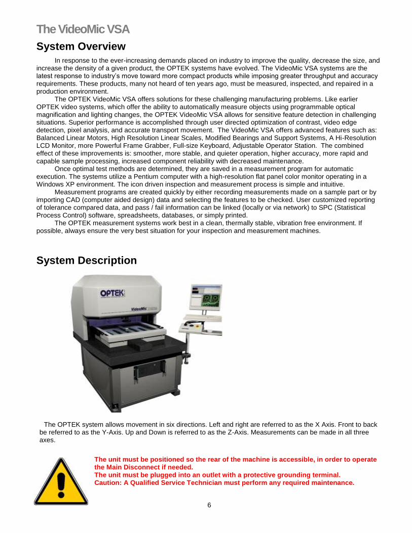
System Description
The OPTEK system allows movement in six directions. Left and right are referred to as the X Axis. Front to back be referred to as the Y-Axis. Up and Down is referred to as the Z-Axis. Measurements can be made in all three axes.
The unit must be positioned so the rear of the machine is accessible, in order to operate the Main Disconnect if needed. The unit must be plugged into an outlet with a protective grounding terminal. Caution: A Qualified Service Technician must perform any required maintenance.

7
Parts Description:
Camera Head Assembly
Z Axis Camera transport
Programmable Zoom Lens
Light Sources: Top light-ring for surface features, On-Axis illumination for indented features. Optional Z-Trac lighting for difficult situations.
X-Y Split-Axis Transport
Hinged Glass Platen used for securing samples for viewing
Interlock safety device to stop all motion.
Optional "Tooling Fences" to secure samples to the stage in a reproducible fashion.
Table Assembly (Granite)
Bottom light for profile work
X / Y Transport Stage
Electronics Area
Electronics boards
Power supplies and amplifiers
Fuses
Rear power switch/circuit breaker
Control panel:
Power switches
Emergency "off "lockout
Joystick for X, Y, and Z
Digital Positioner
Data entry buttons
Computer:
Network Card
Frame Grabber Board
X, Y, and Z Axis board with onboard light, I/O and programmable zoom controller.

8
Part Locations:
Software:
The VideoMic utilizes Microsoft's Windows operating system and Metronics QC5000 application programming for measurements. Third party software is also available to utilize computer-aided design and computer aided manufacturing (CAD/CAM) programs.
Documentation for the OPTEK VideoMic
1. “OPTEK VideoMic VSA Operational Manual QC5000”, this book. 2. The Metronics “QC5000 User’s Guide” describes the software features available to users, programmers,
and maintenance professionals. 3. QC5000 Software on-line help and dialogue boxes: This information becomes available in QC5000 when
you expand a dialogue box, resizing it with the mouse. 4. OPTEK and Metronics Power Point presentations: See your OPTEK representative. 5. Windows on-line help: Accessed through the Windows Graphical User Interface (GUI). 6. The “OPTEK VSA QC5000 Operation Manual” binder includes schematics, optional utilities, and
advanced hardware and software maintenance procedures.
Note: "If the equipment is used in a manner not specified by the manufacturer, the protection provided by the equipment may be impaired."

9
The Control Panel
Power button: This supplies power to the OPTEK. The unit is turned on and off using this button. Emergency Stop Button - All OPTEK units are equipped with an “Emergency Stop" Switch in case of an Emergency. Please make all operators aware of its location and purpose. Mouse - Provides Input to both the computer and the video interface.
When used on the computer monitor it controls all Microsoft Windows functions and all Metronics QC5000 functions. OK button - Press this to preview the data points gathered. Enter button - Press this to accept the data points gathered for a feature. Trackball - This control allows the user to fine position the sample. Joystick - Moves the transport into position in the X and Y-axes and when focusing. Z-Axis Toggle - Switches the function of the Joystick from X/Y movement to Z-Axis movement Fine positioning - Allows for more precise positioning of the transport or Z-axis (focus). The Keyboard - Supplies input to the dialogue boxes, which the software provides. Note - Selecting the Z-axis toggle, "Run" or Fine positioning switches will engage that function for both the joystick and trackball.
10
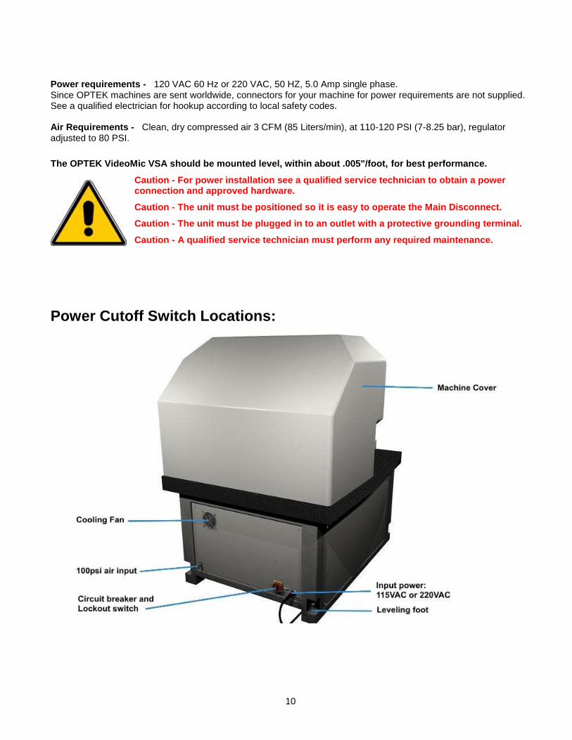
Power requirements - 120 VAC 60 Hz or 220 VAC, 50 HZ, 5.0 Amp single phase. Since OPTEK machines are sent worldwide, connectors for your machine for power requirements are not supplied. See a qualified electrician for hookup according to local safety codes. Air Requirements - Clean, dry compressed air 3 CFM (85 Liters/min), at 110-120 PSI (7-8.25 bar), regulator adjusted to 80 PSI.
The OPTEK VideoMic VSA should be mounted level, within about .005"/foot, for best performance.
Caution - For power installation see a qualified service technician to obtain a power connection and approved hardware.
Caution - The unit must be positioned so it is easy to operate the Main Disconnect.
Caution - The unit must be plugged in to an outlet with a protective grounding terminal.
Caution - A qualified service technician must perform any required maintenance.
Power Cutoff Switch Locations:

11
Operating Principles
The use of the VideoMic depends on five main principles. User Programmability - over movement, focus, magnification, lighting, data acquisition tools, and reporting. Automating these tasks eliminates operator error and speeds throughput. Accurate Positioning - of samples obtained from high acceleration, linear motors, and high accuracy scales to determine position. Path optimization may improve throughput. Non-Linear Error Correction (NLEC) - This software feature allows any errors detected in the measurement system to be corrected automatically. The entire measurement area is mapped and compensated for inherent mechanical errors. Video Edge Detection (VED) - A user programmable feature, which allows the choice of how the software sees a feature. Setting the threshold strength and the VED method provides great flexibility in the types of features, which can be measured. Control over the image from the camera and frame grabber - The QC5000 software and lighting may be used to manipulate the image to enhance weak features and image processing software library functions for the frame grabber take advantage of the video enhancement capabilities. These five main concepts, combined with other principals make the OPTEK VideoMic a teachable, automatic, and accurate measuring device.
Caution: Operation of this equipment assumes some basic knowledge of computers
and MS-Windows software. If you are not familiar with these computer terms please read this manual completely before you power up the OPTEK VideoMic workstation.

12
Chapter 2 Getting
Started
13
OPTEK VideoMic VSA Power On Procedure
Ensure compressed air is being provided at the back of the VideoMic VSA
At the console: 1. Ensure the X and Y axis are positioned in the center of travel. 2. Ensure the “Emergency Stop” button is in the up position. Press the “Power” On button. 3. If necessary, turn on the monitor. Use the individual power button for this. 4. If the PC is not on, turn on the PC and follow the on screen instructions. 5. Ensure the HGP is lowered and no objects are in the light interrupt path. 6. Ensure all Control Panel LED's are off (Fine position & Z axis toggle). 7. Move the transport by hand in all directions. It should move freely. 8. Start QC5000 software using the icon. 9. The VideoMic VSA will automatically proceed through a “homing” sequence. When completed the transport
should be positioned with the camera lens near the center of the glass platen. 10. Conduct a test of the Operator’s controls - joystick, trackball, interlocks, etc.
Caution Note - The transport cannot move with the HGP open. Be certain the HGP is closed while setting Machine Zero.
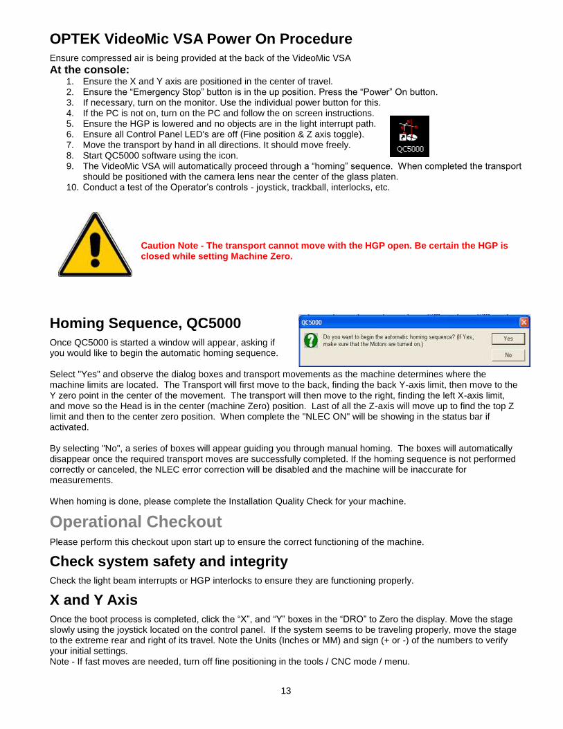
Homing Sequence, QC5000
Once QC5000 is started a window will appear, asking if you would like to begin the automatic homing sequence. Select "Yes" and observe the dialog boxes and transport movements as the machine determines where the machine limits are located. The Transport will first move to the back, finding the back Y-axis limit, then move to the Y zero point in the center of the movement. The transport will then move to the right, finding the left X-axis limit, and move so the Head is in the center (machine Zero) position. Last of all the Z-axis will move up to find the top Z limit and then to the center zero position. When complete the "NLEC ON" will be showing in the status bar if activated. By selecting "No", a series of boxes will appear guiding you through manual homing. The boxes will automatically disappear once the required transport moves are successfully completed. If the homing sequence is not performed correctly or canceled, the NLEC error correction will be disabled and the machine will be inaccurate for measurements. When homing is done, please complete the Installation Quality Check for your machine.
Operational Checkout Please perform this checkout upon start up to ensure the correct functioning of the machine.
Check system safety and integrity
Check the light beam interrupts or HGP interlocks to ensure they are functioning properly.
X and Y Axis
Once the boot process is completed, click the “X”, and “Y” boxes in the “DRO” to Zero the display. Move the stage slowly using the joystick located on the control panel. If the system seems to be traveling properly, move the stage to the extreme rear and right of its travel. Note the Units (Inches or MM) and sign (+ or -) of the numbers to verify your initial settings. Note - If fast moves are needed, turn off fine positioning in the tools / CNC mode / menu.

14
Machine Zero
Machine zero is critical, as it is the reference for the calibration system. The QC5000 will go through a homing process immediately on startup (see Homing Sequence) or, using the mouse, choose the "Set Machine Zero" from the "Datum" menu. This position for X, Y, and Z is the machine zero position. After this process, it is possible to have non-zero numbers in the display. This is OK.
Digital Positioner
Move the Digital Positioner, (trackball). This allows for fine movement. Watch the Digital Read Out (DRO) on the monitor to ensure the trackball is moving one of the axes. If the numbers move in the DRO relative to the axis being moved, the trackball is functioning correctly. Note also the display resolution. This should match the resolution of the encoder scales.
Tooling Fixtures or Hinged Glass Platen.
Check to see if any tooling fixtures are mounted and secure. If a pneumatic system is used, actuate this through its cycle and back.
System Cooling
Verify that the fan is working on the system. The fan is located on the back near the power switches, on the electrical bay side of the unit. The fan will turn on immediately when the green “Power” switch is depressed. There are one or more fans integral to the computer. They are of the automatic type and may or may not be on at that time.
The Computer Display
Screen Window and Video Window
The main display for all functions is the QC5000 screen. The features displayed are identified here and discussed in detail in Chapter 3 of this manual and the “QC5000 User’s Guide”. This display is typical and shows some software capabilities. The display is easily altered and may vary depending on options and how previous operators have chosen to present information. The Main Menu Bar - A horizontal area at the top left of the screen with many drop-down menu choices within it. Status Bar - Found across the bottom of the screen. Used to display information of the current settings and toggle between settings. The DRO - Digital-Read-Out shows the transport X and Y position relative to the reference frame (Datum). Part View - Window displays graphical information of a part and its features. Video - A window that displays the camera (VED tool) image. Where measurements are taken from Results Window - Found at the top right this has numerical measurement information about an individual (highlighted) feature.

15
Feature Stamp - A separate pane opened from a box in the upper left of the “Results Window”. It contains graphical information about the selected feature(s) and distribution of measurement points. Measure Toolbar - Used to measure and construct features. Buttons correspond to items on the “Measure” menu. View - The view toolbar is used to adjust the part view window. Layer control and Toolbars can also be accessed here. Buttons correspond to items on the “View” menu. View Rotator - Changes the display angle of the part view and feature stamp. Tolerance toolbar - Used for performing tolerances on selected features. Tolerances include: run-out, concentricity, parallelism, true positions, etc. Datum - This toolbar is used for establishing various Datum (Zeroing) operations and reference frames. Program: A toolbar used to access programming functions. Buttons correspond to items on the “Tools” menu. Feature (List) - Found as a tab in the “Program” window, this describes the measured features. Program (List) - Found as a tab in the “Program” window, this shows the part program listing. This is a brief introduction to the software display. Amplifying information on each of the above may be found in the “QC5000 User’s Manual” or later in this manual. There is an excellent interactive online manual for QC5000. It is highly recommended that all operators spend some time with the CD-ROM.
Light Control Sliders
The image quality varies with the type of sample being tested and the options chosen in the light control window. Once the OPTEK is turned on and QC5000 is running you must establish the initial settings for the material you are to measure. Note - Although we see colors by the nature of the process, video boards see a monochrome image consisting of black to white and grays in between. All image enhancements are made by making adjustments to the gray scale, which affect the image that the camera sees. The controls have icons for the following optional lighting variations:
Ring Light or Z-Trac (optional) source intensity.
On Axis Lighting source intensity (optional).
Bottom light source intensity
Elevation of the Z-Trac assembly (optional).
Quadrant lighting, selection and intensity (optional).
Quadrant Lighting
Quadrant lighting is available as an option. The icons provide for the lighting of features from the sides for edge detection on highly variable subjects. The quadrants may be turned on or off by clicking on the quadrant position in the icon.
Front Left Right Rear

16
HGP and Lighting
The presence of the Hinged Glass Platen above a sample will affect the behavior of light from the sources above the sample. Keep this in mind when testing light solutions.
General Programming for the VideoMic VSA in QC5000
QC5000 is an advanced software application featuring graphical user interfaces for simple point and click operation. Programming the VideoMic VSA is based on the concept of programming for a specific “part”. Each “part” contains both program steps and session settings. Some steps are good practice to add to any program. With the VideoMic VSA, these steps take on more importance aiding in fluid measurement processing. At the beginning of each program, you should record the following program steps to ensure consistent results: QC5000 must be in the “Record/Edit Program” mode to accomplish some of the following steps. Set point filtration on. Go to / Tools / Options / Point filtration. Check “Enable point filtration” box. Bring the transport to a place where the work may be easily and safely loaded. Set a GO TO LINEAR position for loading a work piece. Tools / Go to / Position. Set initial lighting levels including which light sources are utilized and at what intensity to most clearly distinguish the desired feature. Light settings are saved within program steps. Add a user message. Tools / Programming / Special Steps / User Message: Using a prompt with tips on sample positioning, sample numbering, setting checks or other instructions are helpful. Set tooling, if available, on your system. Employ the user message again here. Teach VED: This records the chosen edge type and edge strength setting. If a program will measure a variety of features that require different Teach and Picture settings, record additional steps to change those settings anywhere in the program, as needed.
1. Program all measurement steps. Go to the unload position. Go to: Tools / CNC mode / Go to Linear to set the unload position near the center of X travel, 1” less than maximum Y travel. This position would also be used for loading the subsequent sample. Do all constructions and reporting. Select features: File / Export. This generates and outputs a report while unloading the part and loading the next. Restart the sequence.

17
Startup Troubleshooting Checklist This is a very short list to help if simple oversights occur. For extensive troubleshooting, consult your supervisor and other documentation provided.
Problems and possible causes
The system does not turn on. Is the red, emergency stop button in the up position? Is the power cord plugged in? Is the line voltage correct (115 VSAC or 220 VAC)? The monitor does not work. Is the monitor turned on? Does it show an image? Is the video cable plugged in? The computer does not turn on. Is the computer power button pressed in? Is the power supply switch turned on (Back of Computer)? Is the line voltage correct (115 VSAC or 220 VAC)? Is the power cord plugged in? Is the computer bios set up to turn on the computer after a power off condition? The printer does not work. Is the printer plugged in and turned on? Is the paper loaded? Is the data cable plugged in? The stage moves by itself. Are the cables in the control panel plugged in? Is the DRO operating correctly? Computer connections terminated properly? Has the joystick teach been performed in software? The transport does not move in one or two directions Did the Homing sequence complete correctly? Was the machine turned on with one or more axis activating a limit switch? The digital positioner (trackball) does not work. Is the digital positioner turned on in the software? Choose “Tools/ CNC … / Digital Positioner Make sure the X and the Y”Enable” boxes are marked. The stage will not move beyond a certain point Did the machine homing sequence complete without errors? Are the software fences (user or machine) setup correctly? From the Datum Menu, choose Set Machine Zero. Follow the on-screen prompts. Cannot see an Image Are the lights adjusted properly? Do you have an object in the field of view? Did the Zoom homing sequence complete without errors after the axis homing sequence?

18
Measuring a part
General considerations prior to measuring
Decide on the orientation of the part, and choose a Zero point. Consider your part drawings if available. Secure the item to be measured on the stage. Use a tooling fixture, a hinged glass platen, or tape. Learn the toolbox options. Set it up to provide the tools you will need for the features to be measured or constructed. (Please see next chapter.) Customize your toolbars. Find an appropriate magnification. Multiple magnifications and associated calibrations are options on the VideoMic VSA. Experiment with lighting. Choose a lighting situation and adjust to give a good firing (edge detection). Use the VED Teach capabilities. Choose a measuring tool, such as circle, buffer, or simple, etc. Select what kind of feature you are measuring, Line, Angle, Circle, etc. “Fire” the tool and view the points obtained to accept or reject the data. Set the Tool configuration for the number of points needed to give a good measurement (Probe/Probe Library / (choose a tool). Set max scans for your configuration). Make any constructions needed for future measurements. Customize a report format for data output.
Preparation for Recording a Part Program
When preparing to write a program, a ten-step process must be completed to allow you to run this program later. This process is as follows: Start a new part. Go to: File / New part. Start the “Record” mode. Measure two features. These may be two tooling holes in the longest axis of the board, or board edges in the X and Y-axis. Skew on either the two tooling holes or the longest axis of the board edges measured. Zero on either the lower left circle or the intersection of the two edges of the board. Measure all of the features required to construct the relationships. Construct points, angles, distances, and heights. Move the stage to a loading position. Report the data to a file. Stop the “Record” mode. Save the program (will get a .5pa part program suffix).

19
Chapter 3
QC5000
Software
This chapter will help you operate the basics of the software.

20
Windows and QC5000 Welcome to one of the most powerful metrology packages available on the market today. QC5000 is a Windows based software package, incorporating pull down menus, data linking, and on-line help.
Getting around in Windows
Since the software is Windows based, the mouse and keyboard can be used to select and manipulate items.
Using the Mouse
The mouse is a tool used for pointing to parts of the screen. Moving the mouse moves the mouse arrow on the screen. Once the arrow is on something you wish to manipulate, a button must be depressed. There are several forms of button pressing. Clicking - Press the LEFT to select or RIGHT mouse button once to access optional features. Clicking the middle, scroll button fires a selected tool. Double Clicking - Press the LEFT mouse button twice quickly. Dragging - Hold down the LEFT mouse button over a file name while moving the Mouse. Dropping - releasing the button in a Drag mode. The mouse is also used on the video area in conjunction with the VED tools. This controls the orientation and position of the tools.
Using the Keyboard Commands executed by the mouse may also be executed using various keystrokes. Pressing the ALT key and the underlined letter of a menu activates menu commands. Once inside a menu, repeat the process or use the up/down arrow keys and press enter once the proper item is selected.
QC5000 Basics The following section will introduce the parts and features of the QC5000 screen. For further information on this or any other part of QC5000, please refer to the “QC5000 User’s Manual”.
The QC5000 Screen #1

21
The QC5000 Screen
The QC5000 screen is made from several individual windows. These are the DRO, Feature List, Results, Part View, and Program View. The Toolbars may be viewed as individual windows or “docked” to the windows they are typically used with. In addition to these windows, a Menu bar, a Status Bar, and a Title Bar can be found on the screen top or bottom. The position of a window may be changed by clicking the title bar and dragging it to a desired location. Window sizes may be changed by moving the cursor over the edges of the pane, clicking and dragging the edge when a double pointed arrow appears. Two considerations for window size and placement are the ease of use and effective use of available screen space, customized for the user. Your screen may differ from the examples seen in this manual. The following section will introduce the parts and features of the windows.
The Title Bar
The Title Bar is always located on the top of a window. You will find the name of the software and the part file that is currently running.
The Menu Bar
The Menu Bar lists all available menus. Because QC5000 is capable of having several options, the Menu Bar will display only the options available according to the systems options.
The Status Bar
The Status Bar usually contains the time, date, unit of measure, and coordinate system. When visible, it will appear at the bottom of the screen and is used to toggle between settings. Items may be added or removed from the status bar through Tools/Customize/Status bar.
The DRO window (Digital Read Out)
The DRO window Shows the current tool position in the X, Y, and Z-axis relative to the Datum. Next to each axis is a button with the axis name on it. Clicking on these buttons with your mouse, or pressing the appropriate key on the keyboard, zeros that axis at the present position. A Zero point may also be entered through the Datum/Zero… menu or toolbar. The Part View Window The Part View is the graphical representation of the part being measured. The Feature List Window The Feature List is where the measured, created, or constructed features are placed. The Results Window The Results Windows displays all geometric information about the current selected feature. In addition to this information, the Results Window contains two menus, Tolerancing and Change.
22
The Program View Window The Program View Window displays the steps within a recorded program. The Unit of measure and Coordinates are toggles. Each time these commands are selected, they will toggle between Inch and Millimeter or Cartesian and Polar.
Customization
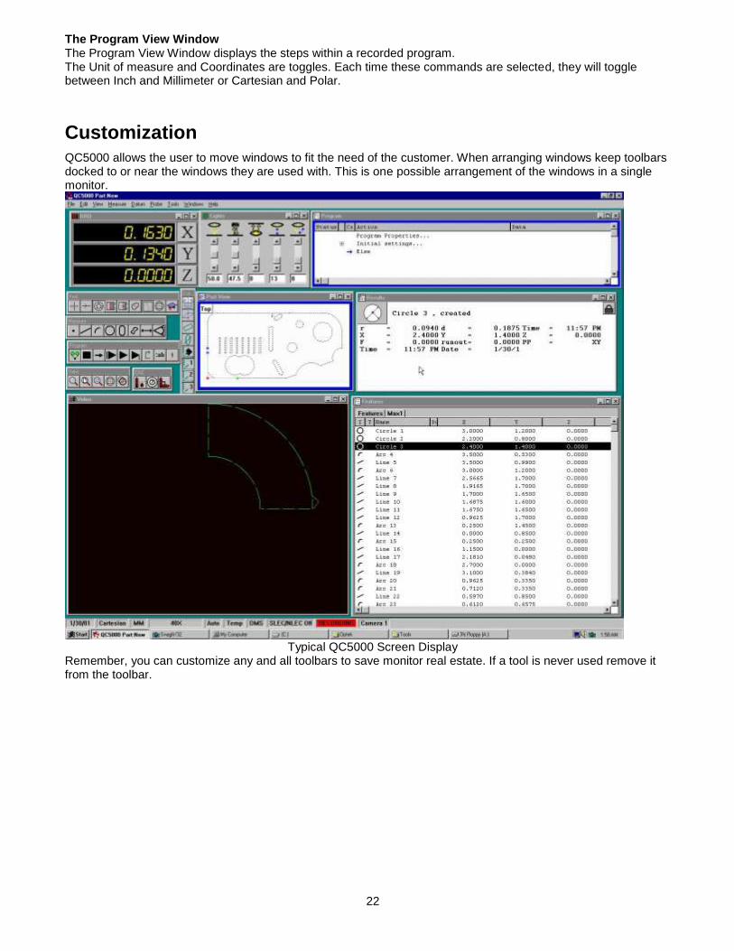
QC5000 allows the user to move windows to fit the need of the customer. When arranging windows keep toolbars docked to or near the windows they are used with. This is one possible arrangement of the windows in a single monitor.
Typical QC5000 Screen Display
Remember, you can customize any and all toolbars to save monitor real estate. If a tool is never used remove it from the toolbar.
23
QC5000 Tables
Toolbars in QC5000
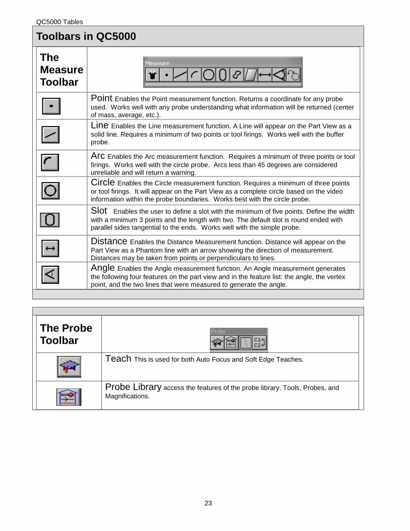
The Measure Toolbar
Point Enables the Point measurement function. Returns a coordinate for any probe
used. Works well with any probe understanding what information will be returned (center of mass, average, etc.).
Line Enables the Line measurement function. A Line will appear on the Part View as a
solid line. Requires a minimum of two points or tool firings. Works well with the buffer probe.
Arc Enables the Arc measurement function. Requires a minimum of three points or tool
firings. Works well with the circle probe. Arcs less than 45 degrees are considered unreliable and will return a warning.
Circle Enables the Circle measurement function. Requires a minimum of three points
or tool firings. It will appear on the Part View as a complete circle based on the video information within the probe boundaries. Works best with the circle probe.
Slot Enables the user to define a slot with the minimum of five points. Define the width
with a minimum 3 points and the length with two. The default slot is round ended with parallel sides tangential to the ends. Works well with the simple probe.
Distance Enables the Distance Measurement function. Distance will appear on the
Part View as a Phantom line with an arrow showing the direction of measurement. Distances may be taken from points or perpendiculars to lines.
Angle Enables the Angle measurement function. An Angle measurement generates
the following four features on the part view and in the feature list: the angle, the vertex point, and the two lines that were measured to generate the angle.
The Probe Toolbar
Teach This is used for both Auto Focus and Soft Edge Teaches.
Probe Library access the features of the probe library. Tools, Probes, and
Magnifications.
24
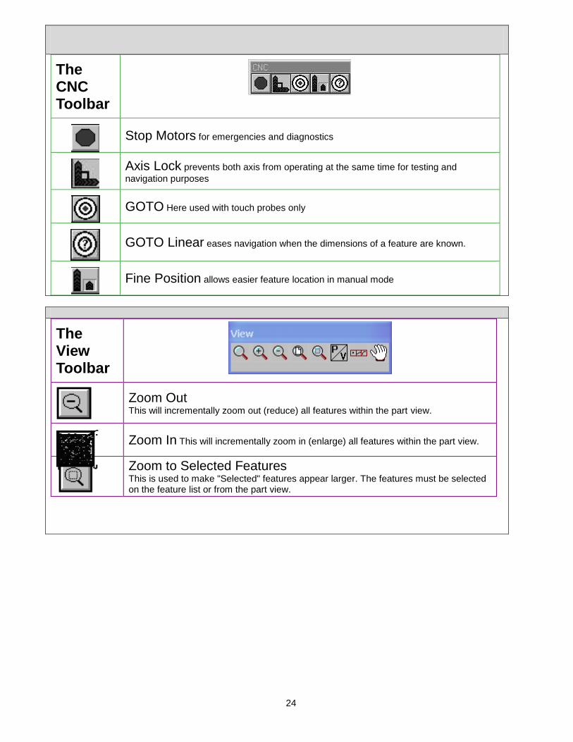
The CNC Toolbar
Stop Motors for emergencies and diagnostics
Axis Lock prevents both axis from operating at the same time for testing and
navigation purposes
GOTO Here used with touch probes only
GOTO Linear eases navigation when the dimensions of a feature are known.
Fine Position allows easier feature location in manual mode
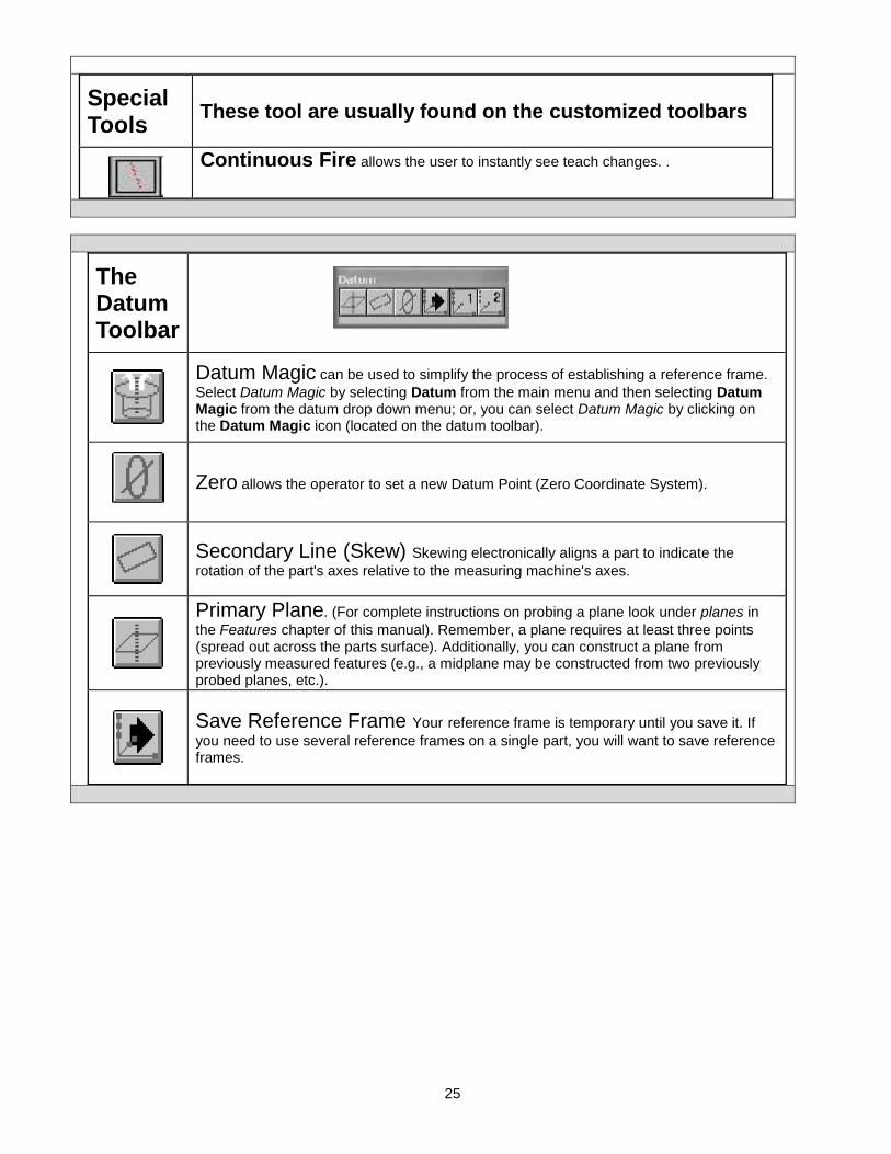
The View Toolbar
Zoom Out This will incrementally zoom out (reduce) all features within the part view.
Zoom In This will incrementally zoom in (enlarge) all features within the part view.
Zoom to Selected Features
This is used to make "Selected" features appear larger. The features must be selected on the feature list or from the part view.
25
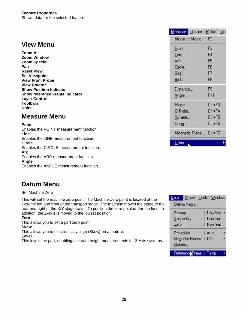
Special Tools
These tool are usually found on the customized toolbars
Continuous Fire allows the user to instantly see teach changes. .
The Datum Toolbar
Datum Magic can be used to simplify the process of establishing a reference frame.
Select Datum Magic by selecting Datum from the main menu and then selecting Datum Magic from the datum drop down menu; or, you can select Datum Magic by clicking on the Datum Magic icon (located on the datum toolbar).
Zero allows the operator to set a new Datum Point (Zero Coordinate System).
Secondary Line (Skew) Skewing electronically aligns a part to indicate the
rotation of the part's axes relative to the measuring machine's axes.
Primary Plane. (For complete instructions on probing a plane look under planes in
the Features chapter of this manual). Remember, a plane requires at least three points (spread out across the parts surface). Additionally, you can construct a plane from previously measured features (e.g., a midplane may be constructed from two previously probed planes, etc.).
Save Reference Frame Your reference frame is temporary until you save it. If
you need to use several reference frames on a single part, you will want to save reference frames.

26
VED TOOL BAR
Tools are sometimes called Probes
New Tool This creates a custom tool to the situation
Crosshair — The Crosshair probe is the only probe that does not perform edge
detection. This probe is used to stake a point and send the X/Y coordinates to the QC5000.
Simple — A Simple probe is used to find a single edge point.
Buffer — The Buffer probe is the only probe that will return multiple points to the
QC5000. You can select between 1 and 100 points on the Buffer probe.
Nearest — The Nearest probe is a block probe used to find the nearest X/Y
coordinates from the direction of the arrow.
Farthest — The Farthest probe is a block probe used to find the farthest X/Y
coordinates from the direction of the arrow.
Average — The Average probe is a block probe used to find the average X/Y
coordinates of all points detected on a poorly defined or rough edge.
Circle — The Circle probe is used to find the diameter and center X/Y coordinates
of a circle. Uses LMC, MMC and with the least squares best-fit algorithm.
Width — The Width probe will scan the edge of two lines and return one point on
each edge, use this with the distance command.
Height — The Height probe will perform an auto focus and return a point with a
critical "Z" value. Construct a distance from a plane in the Z.
Light to Dark use as VED Edge detection preference
Dark to Light use as VED Edge detection preference
Blob — VED tool will return the "center of a mass location" of an irregularly
shaped object.
The QC5000 Menus
Each item found in the Main Menu Bar consists of a pull down menu items, which correspond to many toolbar options. The following information gives a brief explanation of the menus. For more information, please consult the “QC5000User’s Guide”, or use the on-line help system. QC5000 utilizes the concept of the “part” and “run” to

27
retrieve data saved in a measurement programming session. This includes templates and databases in use along with the part program.
The File Menu
New Part/Run New / Part allows the system to clear all data. When chosen, the system will revert to the Machine Zero and Machine Skew. Also, all data in the Feature List will be erased. Open Closes the current “part” and opens a previously saved “part” file. Save Saves the current data to an existing, open “part” file. Save As This saves the current data to a newly created “part” file. Import This function is used to transfer DXF TAP or IGS files into the QC5000 software. Export All highlighted data will be exported to a DXF file . Print Preview This will show the contents of the print buffer. DDE Output Sends Data to an external application Exit To Windows This will close the QC5000 and exit to the Windows operating environment.
Edit Menu
Cut Selected Features This function is used in programming and transferring information to other applications. Copy Selected Features This function is also used in programming and transferring information to other applications. Paste / Paste Special This function will insert information from the clipboard to an application. This is used in programming and transferring information to other applications. Delete Selected Features All selected features in the “Features” list will be deleted. Select All Features This will select all features found in the “Features” list. Deselect All (Select None) Features This will deselect all features highlighted from the “Features” list. Find Feature This will choose all the features that match the search criteria. Change Feature Allows the user to change the selected “Feature” Name
28
Feature Properties Shows data for the selected feature.
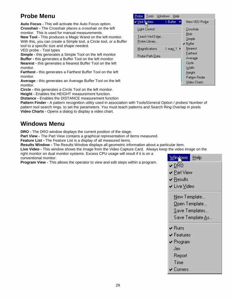
View Menu
Zoom All Zoom Window Zoom Special Pan Reset View Set Viewpoint View From Probe View Rotator Show Position Indicator Show reference Frame Indicator Layer Control Toolbars Units
Measure Menu
Point Enables the POINT measurement function. Line Enables the LINE measurement function. Circle Enables the CIRCLE measurement function. Arc Enables the ARC measurement function. Angle Enables the ANGLE measurement function.
Datum Menu
Set Machine Zero
This will set the machine zero point. The Machine Zero point is located at the extreme left and front of the transport stage. The machine moves the stage to the rear and right of the X/Y stage travel. To position the zero point under the lens. In addition, the Z-axis is moved to the lowest position. Zero This allows you to set a part zero point. Skew This allows you to electronically align (Skew) on a feature. Level This levels the part, enabling accurate height measurements for 3-Axis systems.
29
Probe Menu
Auto Focus - This will activate the Auto Focus option. Crosshair - The Crosshair places a crosshair on the left monitor. This is used for manual measurements. New Tool - This produces a Magic Wand on the left monitor. With this, you can create a Simple tool, a Circle tool, or a Buffer tool to a specific size and shape needed. VED probe - Tool types Simple - this generates a Simple Tool on the left monitor Buffer - this generates a Buffer Tool on the left monitor. Nearest - this generates a Nearest Buffer Tool on the left monitor. Farthest - this generates a Farthest Buffer Tool on the left monitor. Average - this generates an Average Buffer Tool on the left monitor. Circle - this generates a Circle Tool on the left monitor. Height - Enables the HEIGHT measurement function. Distance - Enables the DISTANCE measurement function Pattern Finder - A pattern recognition utility used in association with Tools/General Option / probes/ Number of pattern tool search rings, to set the parameters. You must teach patterns and Search Ring Overlap in pixels Video Charts - Opens a dialog to display a video chart.
Windows Menu
DRO - The DRO window displays the current position of the stage. Part View - The Part View contains a graphical representation of items measured. Feature List - The Feature List is a display of all measured items. Results Window - The Results Window displays all geometric information about a particular item. Live Video - This window shows the Image from the Video Capture Card. Always keep the video image on the right monitor on dual monitor systems. Excess CPU usage will result if it is on a conventional monitor. Program View - This allows the operator to view and edit steps within a program.

30
Templates as Windows
All templates are opened and saved from here. It is recommended that the user save templates with a unique name. This ensures the original templates remain unchanged. The new template name will show at the bottom of the menu list. Runs - opens the runs database window template. Features - opens the features window template. Program - opens the program listing window template. Reports - opens the reports window template. Time - opens the runs database (Time) window template. Corners - opens the runs database (Corners) window template. Jim - opens the runs database (JIM) window template.
Probes-VED Teach
Turn soft edge off in / Programming / special steps to view this histogram and dialog. Teach - The Teach Tool is used to teach edge characterization. Either - edge type dark or light Light to Dark - This tool will force the current probe to seek edges going from a Light area to a Dark area. It will only seek edges in the same direction that the arrow of the probe is pointing. Dark to Light - This tool will force the current probe to seek edges going from a Dark area to a Light area. It will only seek edges in the same direction that the arrow of the probe is pointing. First Edge - This tool will scan in the direction of the probe arrow, seeking the first edge it encounters. Strongest - This tool will scan in the direction of the probe arrow, seeking the strongest edge it encounters. Auto - Automatically picks an edge Soft Edge Teach - Sets the edge found as a percentage across total transition under the probe
View Menu Zoom In - This incrementally makes the features in the Part View larger. Zoom Out - This incrementally makes the features in the Part View smaller. Zoom to Selected Features - This zooms in on the features selected in the Feature List. Preset View - Selects from CAD style views for 3D systems. Show Reference Frame Indicator. A Toggle. Record Zoom - This command is for the Programming Mode. The present Zoom will be recorded as a step in the program for a visual aid to the operator. Show Position Indicator - This will turn the position indicator on or off in the Part View. Layer Control - This will redraw all the features in the Part View for 3D systems only. Toolbars Access’ the available toolbars on each system includes custom toolbars. Units switch from inches to millimeters and back.
The Tools / Programming Menu
The PROGRAM menu is unlike the other menus, in that different menu selections will appear as the operator enters different modes of programming. The following lists all program menus and the mode the operator must be in for the selection to appear. The mode will appear in {brackets}, and will indicate if the selection will appear {Prior} to recording a program, {During} a programming session, {After} programming, or while {Editing} a program.
31
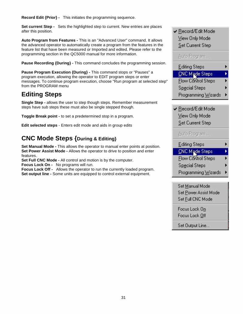
Record Edit {Prior} - This initiates the programming sequence. Set current Step - Sets the highlighted step to current. New entries are places after this position. Auto Program from Features - This is an "Advanced User" command. It allows the advanced operator to automatically create a program from the features in the feature list that have been measured or Imported and edited. Please refer to the programming section in the QC5000 manual for more information. Pause Recording {During} - This command concludes the programming session. Pause Program Execution {During} - This command stops or "Pauses" a program execution, allowing the operator to EDIT program steps or enter messages. To continue program execution, choose "Run program at selected step" from the PROGRAM menu
Editing Steps
Single Step - allows the user to step though steps. Remember measurement steps have sub steps these must also be single stepped though. Toggle Break point - to set a predetermined stop in a program. Edit selected steps - Enters edit mode and aids in group edits
CNC Mode Steps {During & Editing}
Set Manual Mode - This allows the operator to manual enter points at position. Set Power Assist Mode - Allows the operator to drive to position and enter features. Set Full CNC Mode - All control and motion is by the computer. Focus Lock On - No programs will run. Focus Lock Off - Allows the operator to run the currently loaded program. Set output line - Some units are equipped to control external equipment.
32
Flow Control Steps
Loop - Create a repeating grid or array of features If then - A conditional Statement checking a value or formula If Goto - Conditional to go to a label Else - a Label to direct the flow to a new sub step. Goto Label - A redirect from a sub step Label - used to create a sub step or routine Offset Positions - Allows you to manually enter a coordinate that will offset the current coordinate Save Offset Positions - Saves the Offset position Restore Offset positions - Restores saved Offsets
Software and Menus
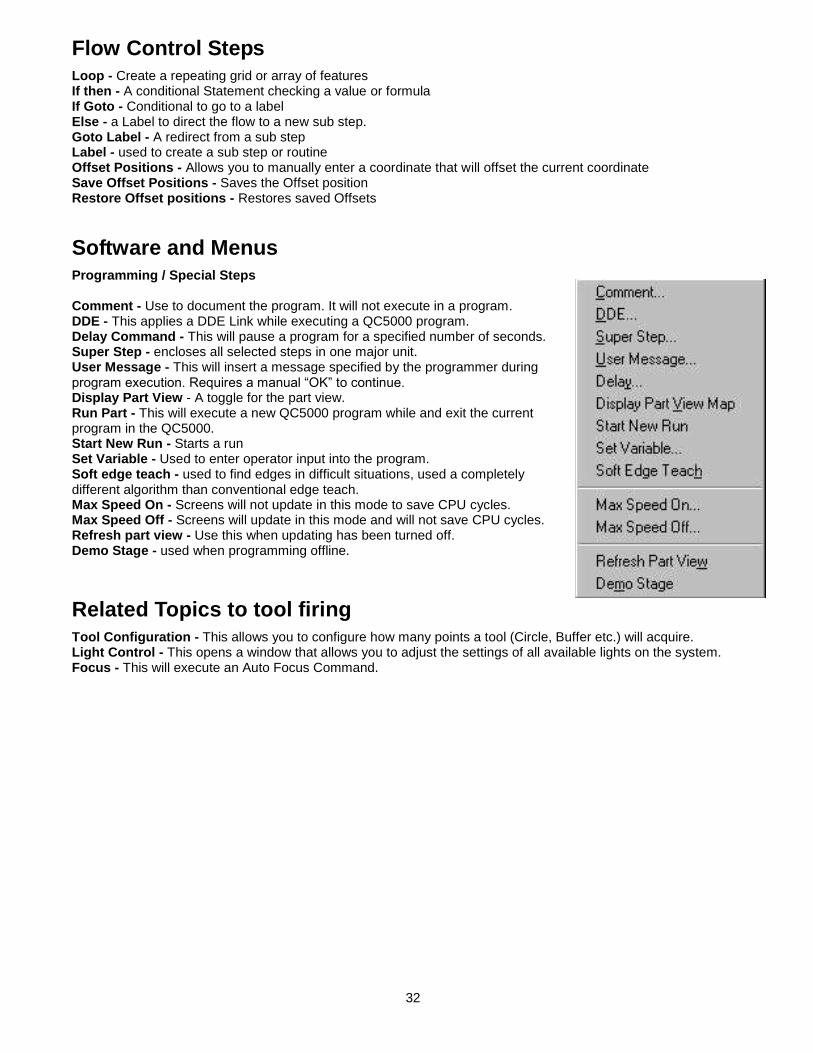
Programming / Special Steps Comment - Use to document the program. It will not execute in a program. DDE - This applies a DDE Link while executing a QC5000 program. Delay Command - This will pause a program for a specified number of seconds. Super Step - encloses all selected steps in one major unit. User Message - This will insert a message specified by the programmer during program execution. Requires a manual “OK” to continue. Display Part View - A toggle for the part view. Run Part - This will execute a new QC5000 program while and exit the current program in the QC5000. Start New Run - Starts a run Set Variable - Used to enter operator input into the program. Soft edge teach - used to find edges in difficult situations, used a completely different algorithm than conventional edge teach. Max Speed On - Screens will not update in this mode to save CPU cycles. Max Speed Off - Screens will update in this mode and will not save CPU cycles. Refresh part view - Use this when updating has been turned off. Demo Stage - used when programming offline.
Related Topics to tool firing
Tool Configuration - This allows you to configure how many points a tool (Circle, Buffer etc.) will acquire. Light Control - This opens a window that allows you to adjust the settings of all available lights on the system. Focus - This will execute an Auto Focus Command.
33
Chapter 4
QC5000
Calibration

34
Calibration of the VideoMic VSA in QC5000
Calibration Procedure Overview
A Complete calibration consists of both optical calibrations and calibration of the movement system. Optical: Check parfocality and parcentricity first. Mechanical squareness and camera rotation adjustments follow and then software adjustments to the imaging system using the probe library. Movement: The transport movement is then determined and incorporated into the calibration using NLEC (Non Linear Error Correction).
Adjustments to the Camera System
Camera Rotation - A mechanical adjustment. Pixel calibration - Software compensation. Camera Rotation Calibration - Software compensation. Camera Offset - For multiple Magnification Systems
Adjustments to the Transport system
Preparations - Remove any tooling, which might interfere including the HGP. Grid Alignment - Mechanical adjustment. Grid Measurement - Determines the errors and applies software compensation by NLEC calibration. Implementation of NLEC Calibration - Software compensation for errors. Verification - The calibration check program: Software verification of the compensation by NLEC.
Calibration Procedure Do squareness or camera rotation first. Pixel cal can be approximate at this point
Adjusting the Camera Squareness
(A Mechanical Rotation which is only required if the machine or camera system is moved.) The next step in the alignment process is to ensure the camera is square to the X-axis travel. With a large crosshair on the video monitor, place a sharp image all the way to the left side of the screen just touching the horizontal line of the crosshair. Move the image to the right side of the screen with the joystick. The object should follow the line. If the does not follow the crosshair line, loosen the two camera mount set screws (Also used in adjusting Parfocality) and rotate the camera until the image stays on the line from left to right. Tighten the setscrews when the image touches the line from left to right.
Camera Rotation Correction
(Software Alignment) Position a dot resting tangential to the crosshair tool horizontal centerline, on the Video window at the left side of the field of view. From the CNC toolbar choose Axis Lock Tools \ General \ Password \ Enter the security code. Choose: Probe \ Probe library. Select “VED” from the left side window and “Camera” from the right side. Select the “Orientation” tab to adjust Camera Skew. Click the Teach button. A calibration circle tool will appear on the Video monitor. An instruction box will appear on the right. Follow these instructions to complete the Camera Rotation Correction. This completes the Camera Rotation Correction. Exit this window by pressing OK.

35
Pixel Calibration
Assuring that the feature measures at the correct size. All measurements are performed by calculating pixels. These pixels have a set value that is determined through a simple calibration process. If the pixels are not calibrated, any measurements made will be incorrect. The pixel calibration is based upon the Calibration Slide. The standard Calibration Slide shipped with the system is for reference only. This is not a traceable item. If a traceable Calibration Slide is needed, please contact your OPTEK representative or contact Operations Technology, Incorporated for more information.
Set the QC5000 to metric units. To perform a calibration, the light levels must be set correctly. Position the slide under the camera so
the dot can be seen on the Video monitor, taking up more than half of the video screen. Adjust the light settings as low as possible, maintaining a clear image in the Video window. Position the dot as close as possible to the center of the Video monitor. Go to - Probe \ Probe library. Click the magnification of interest and choose the “Resolution” tab. Select “Teach” to edit the calibration. Enter the size of the calibration dot. The actual size of the dot is found on the back of the calibration slide case. Arrange the calibration probe to cover the dot and double click to cause the probe to shoot from dark to light. Check the feature view to determine if the dot diameter matches the slides given diameter When you do a pixel calibration this dialog box will come up to prompt you to enter the size of the artifact you are using to calibrate with. The size usually comes from the VED glass slide supplied with the system. If you select continue the system will prompt you to measure the specified artifact. If you say cancel it will return you to the Probe Library window. After the appropriate information has been placed in the Standard Size area, select the circle tool twice. This will center the tool in the Video window. Using the digital positioner (track ball). Move the transport system until the dot is as close to the center of the circle tool as possible. Size the circle tool to fit over the dot properly. Click the right mouse button. The system will measure the dot three times. From this the X and Y pixel dimensions will be determined. The present pixel value can be seen in the Pixel Size window. Continue this procedure until all magnifications have been taught. Click OK to exit the Learn VED Pixel Size window. Click OK to exit the Edit Calibration window.

36
QC5000 Calibration procedure for the Probe Library
This operation is for factory representatives who are installing new QC5000 operating system computers to existing machines.
1. Setup your Magnifications. 2. Assign Zoom Positions. 3. Teach Autofocus and Video Edge Detection. 4. Pixel Calibration. 5. Camera Skew. 6. Parcentricity Calibration. 7. Go back and check all the calibrations by measuring the
appropriate artifacts. This is an extremely important part of the QC5000. This is the place to set up your Camera / Magnifications / VED tools and do all your calibrations. Probe Library works a lot like Windows/NT explorer. Click something on the left, it opens up and expands to the right. If you turn on Auto Finish it will make calibrating easier.
Remember anything you want to calibrate must be on the right side!
Probe Library: Mag Tab
Selecting “new” creates a new magnification. Selecting delete, removes a magnification. Disqualify erases the data in the current calibration. Warning, do not select load unless the rack has been properly setup Selecting OK exits Probe Library
Probe Library - VED Probes
This is the section of Probe Library where you set up how many points will be taken when you fire a video probe. Max scans tell you how many points per firing. Edge type indicates dark to light, light to dark-or first edge algorithm. Type describes which algorithm will be used, Auto, Strongest or First. Teach performs an edge teach.

37
Probe Library: Autofocus Tab
This is where you teach the AUTOFOCUS range of each magnification. You must do a TEACH for each Magnification. You can also set a search Distance manually. If you teach from here, you can use most VED Tools. Remember a safe distance is in the up direction. Make sure your “Z” is counting positive in the up direction.
Probe Library: Resolution Tab
Select teach to do your Video Pixel Calibration. You MUST calibrate each magnification. Notice the size of a pixel at each magnification. Remember we do sub-pixel edge detection. The QC5000’s edge detection is far superior to the QC4000. The edge detection is extremely sensitive in low light settings.
Camera Calibration- Camera SKEW
This is the section of Probe Library where you do your Camera Calibration. If you click on “Teach” Probe Library walks you through doing a camera Skew calibration. If your camera image is backwards or opposite you can change the Orientation here. Remember to make this one of your first calibrations.

38
Probe Library-Offset Tab
This frame shows the offset from magnification Med High to the master mag High. These offset are also known as parcentricity and parfocality. If you click on teach the system will walk you through the calibration. You should start this procedure at Med High. Notice reference is not checked. Only the master probe (HIGH) in the group is checked. The same calibration needs to be done for each of the other magnifications, except High, which is the Master Probe in this group.
Transport Movement Calibration
QC5000 Grid Calibration Procedure
OVERVIEW
1. Start QC5000 (Ensure that all other optical and mechanical adjustments and calibrations have been done first.)
2. Turn off the NLEC. Click on (Tools \ Options \ Nlec) and uncheck the (Nlec Enabled) check box. 3. Open the calibration program. This should be in (C:\Optek\Calibration\ Calibration.5pa). 4. Place toggle breakpoint after skew and zero steps. Right click on the first grid measurement step. Click on
(Editing steps \ Toggle break point). 5. Open NLEC controller. Click on (Tools / Options / NLEC, Click Calibrate) 6. Right click in the background between grid stations. 7. For certified grids only. Click on (File \ Import) and browse to the ACF file that matches the Grid s/n. For
other grid masters, click on (File \ New) and enter all relevant information. 8. Verify columns / rows correct for grid stations to be used. 9. Right click in the background between grid stations. 10. Click on (Calibrate \ Start). 11. Run the program. Click on the (New Run) button. The machine will measure the skew and zero points and
then stop at the break point that was set in step #4. 12. In the NLEC controller window, right click on the lower left grid station, and then left click on (Zero). This
tells the NLEC controller where the zero and skew line exist. 13. Click on the button (Run from current step), this runs the program from the first grid measurement step.
Most tolerances will show up as failed (RED) and should be ignored at this point. 14. When the program is finished running. In the NLEC controller window, right click in gray area. Then click on
(File\ Save) give it a sensible name (NLEC Reference) and save it in: C:\ QC5000 as – (“date of cal “.txt). This save is just for a calibration record.
15. In the NLEC controller window, right click in gray area again. Then click on (File \ export) and accept the default name and location for the export. This exports all of the adjusted NLEC grid data from the controller to a text file that will be read by the QC5000.
16. Turn on the NLEC. Click on (Tools / Options / NLEC) and put a check mark in the box (Enable). 17. Shut down QC5000 and restart.
Verify the Calibration
Choose the calibration program. (File / Open / “calibration check .5pa”) Add Fields to the features template. Check the calibration, note the x difference from nominal and y difference from nominal fields to the feature window. Measure the grid with the same program as in calibration with no changes in edge teach or lighting. The tolerances should now be green with NLEC enabled. Export the data. Save as “CAL Data and date of calibration” .csv file Recalibrate if necessary.

39
OPTEK Ultra Precision Grid Method.
Use if an Ultra Precision Grid and calibration ACF AND DXF data files are available. 1. Optionally, a part program can be used to measure the calibration grid. (Recommended) 2. Create a part program from the import of a DXF file, which represents the ACF data. Turn NLEC off. Go to
program properties and uncheck use machine zero. Record a skew and zero. Import the DXF. Choose record. Select the imported features from the features list. Choose tools programming auto program from features. In the program window, group edit the measurement steps for scan direction edge transition and tolerance. Place a toggle breakpoint after the skew and zero steps and save the program. Follow the directions as given in the overview at the beginning of this section.
3.
The NLEC Controller
Menu Options
File/New - Create a new grid data file from scratch. File/Open - Open an existing grid data file (QC5000 v2 format) File/Import - Import an artifact file ACF (QC4000 format) File/Edit - Edit the existing grid header information File/Export - Export the error information to a calibration file (QC4000 format) File/Save - Save existing grid data along with its calibration information (QC5000 v2 format) Orient/Rotate Plus - Rotate the grid data 90 degrees counter-clockwise Orient/Rotate Minus - Rotate the grid data 90 degrees clockwise Orient/Flip Horizontal - Flip the grid data about the horizontal axis (top to bottom) Orient/Flip Vertical - Flip the grid data about the vertical axis (left to right) Whisker/ xxx - Select the error whisker magnification, or turn it off Calibrate/Start - Start the grid calibration process Calibrate/Restart - Re-start the calibration process from the beginning Calibrate/Cancel - Terminate the calibration process without saving the data Calibrate/Import - Import the calibration data from the features already in the feature list
Perform a datum/skew measuring two grid features along an edge. For best results the features should be as far apart as possible.
File > Orient >
Whisker > Calibrate >
New… Open… Import… Edit… Export… Save…

40
NLEC Background Information
Non-Linear Error Correction User Interface Design in QC5000
The objective of this design is to provide a service technician with the ability to create and update the NLEC tables within the QC-5000v2. It does this by providing a simple interface to assist in the manipulation of artifact and calibration data. Using this interface, calibration proceeds as follows:
1. Start the QC5000 software and ensure that the machine zero is set correctly. Select the menu item Tools/Options. The “Supervisor” tab will display. Enter the password, check the box to keep privileges then select the “General Options” tab. Select the NLEC tab. Press the Calibrate button. The NLEC Controller Window will open. Close the Options dialog to proceed with using the NLEC controller window.
2. There are two ways to generate nominal grid data. You can import an artifact data file, or create a new data set from scratch. Use a right button click on the grid background to open the NLEC menu. To import a file, proceed to step 3. To create a new data file, proceed to step 4.
3. Select File/Import to import an artifact data file (ACF) and produce an output file that represents the points that will actually be measured for calibration. Use the graphic tools within this window to rotate, flip, and/or select a subset of grid points as needed. The Orient menu allows you to rotate and/or flip the grid data to line it up with the way the artifact will be placed on the measuring stage. You can drag a selection rectangle around a group of grid points to de-activate all of the points outside the selection rectangle. Use the Edit dialog to enter the grid header information. When complete, select File/Save to save the grid data in QC5000 v2 format. You will need to repeat this process only if a different calibration artifact is used, if the same calibration artifact is used in a different orientation, or a different subset of grid points is measured. Otherwise, the resulting calibration data file can be used repeatedly for several calibrations. Use File/Open when you want to use the same artifact file again. Please see the end of this section to create this file if not present in you calibration directory or the OPTEK directory.
4. To create a grid data file from scratch, select File/New. Fill in the fields in the dialog box. It is important to correctly enter the grid type, grid units, grid dimensions and grid element spacing. This information is used to generate a nominal grid, and it will control the calibration process. The other information is used for traceability. Select OK to generate a nominal grid. You can then use right button selection over a grid element to view the grid data. The grid point edit dialog can also be use to adjust the grid nominal data if calibration information is available for the grid. When editing is complete, select File/Save to save the grid data in QC5000 v2 format.
5. Select Calibrate/Start to start a calibration process. A series of instructions will then be displayed to lead you through the calibration process.
6. Grid features must be circles for a Circle grid type, and points created as line intersections for a Cross grid type. Measure two of the active grid features along one edge to establish skew. Measure the single point in the most lower-left active grid point corner to establish zero. Next, measure each one of the grid points. Each measurement will be indicated in the artifact display so that you can keep track of progress. When the measurements are completed, select File/Export to create an NLEC correction file. This file must be named NLEC.TXT in order to make it the active calibration file.
7. The right button Whiskers menu can be used to control the display of short lines that represent the difference between the measured and grid data. This can be turned on after grid measurement is complete, or before measurements are made.
8. Optionally, a part program can be used to measure the calibration grid. Run a part program that establishes skew and zero and measures each of the grid elements. Then select Calibrate/Import to process the data from the feature list. Select File/Export (“nlec.txt”) to create an NLEC correction file.
9. When calibration is complete you can also select File/Save to save a complete calibration report including nominal, measured and deviation data. This file should be given a different name than the grid data file saved in step 3 or 4.

41
CALIBRATION FILE (Background)
This file is maintained for each calibration artifact position on a given machine. It contains the nominal, actual and deviation information for a set of points in an error grid. Before calibration the measured data is equal to the nominal data and the deviation is zero. After calibration the measurement results and deviation are recorded. This file is not used by the NLEC routines to correct raw machine coordinates. The data must be exported to a QC4000 format NLEC correction file (nlec.txt). Sample contents of this file follow: Calibration File ID Art1_Full_90_Deg Calibration File Version 1.0 Machine Type OPTEK 1273V Machine Serial Number OTI 012345 Machine Calibration Date 07-September-1999 Artifact File Path C:\QC5000\calib\A96352.art Artifact Serial Number 96352 Measurement Units mm Artifact Grid Type Circle Artifact Zero Column(x) 1 Artifact Zero Row(y) 1 Artifact Skew Pnt 1 Col(x) 1 Artifact Skew Pnt 1 Row(y) 1 Artifact Skew Pnt 2 Col(x) 5 Artifact Skew Pnt 2 Row(y) 1 Number of Columns (nx) 3 Number of Rows (ny) 5 First Active Column (x0) 1 First Active Row (y0) 2 Last Active Column (x1) 3 Last Active Row (y1) 5 Column Spacing (dx) 25.4000 Row Spacing (dy) 25.4000 Artifact Element Size 0.0500 NLEC Zero X (machine) 19.8765 NLEC Zero Y (machine) 43.2109 Artifact Skew Angle 0.0765 User Note This artifact must be cleaned before use. Column Row Artifact X Artifact Y Measured X Measured Y Error X Error Y ====== ===== ========== ========== ========== ========== ======== 1 1 0.0000 0.0000 0.0000 0.0000 0.0000 0.0000 1 2 0.0000 25.4000 0.0000 25.4000 0.0000 0.0000 1 3 0.0000 50.8000 0.0000 50.8000 0.0000 0.0000 1 4 0.0000 76.2000 0.0000 76.2000 0.0000 0.0000 1 5 0.0000 101.6000 0.0000 101.6000 0.0000 0.0000 2 1 25.4000 0.0000 25.4000 0.0000 0.0000 0.0000 2 2 25.4000 25.4000 25.4000 25.4000 0.0000 0.0000 2 3 25.4000 50.8000 25.4000 50.8000 0.0000 0.0000 2 4 25.4000 76.2000 25.4000 76.2000 0.0000 0.0000 2 5 25.4000 101.6000 25.4000 101.6000 0.0000 0.0000 3 1 50.8000 0.0000 50.8000 0.0000 0.0000 0.0000 3 2 50.8000 25.4000 50.8000 25.4000 0.0000 0.0000 3 3 50.8000 50.8000 50.8000 50.8000 0.0000 0.0000 3 4 50.8000 76.2000 50.8000 76.2000 0.0000 0.0000 3 5 50.8000 101.6000 50.8000 101.6000 0.0000 0.0000
Row and column are the artifact grid point numbers. Columns are tab-delimited so that the data can be easily read into Excel.

42
Entering the Grid Data by ACF (Artifact Coordinate File)
The grid manufacturer normally supplies calibration data for a grid as a report. The data must be put into a format that the NLEC Manager can understand. After this file is created, it is saved as a file with an extension of .ACF. Import the file into MS Excel. MS Excel helps here, as columns must be deleted. Save as a text file. Using a text editor, create a file in the format (Gray) shown below and save the file with the extension .ACF:
MM Y Units and Skew axis X Position Y position
30.0000 30.0000 Spacing
4 5 Rows and columns
0.080 0.035 Origin point 0 0
29.291 0.047 Second point 30 0
59.356 0.023 Third point 60 0
.0022 29.9968 Row increment on the grid 0 30
29.0040 29.9980 Second row second point. 30 30
60.023 29.9890 Second row third point 60 30
Note - A TAB character separates the left and right columns. The skew axis is not used at this time and can be either X or Y.
Once ACF file is generated save for the grid calibration process. When finished, a message appears informing you the operation has been completed.

43
Chapter 5
Troubleshooting

44
Symptoms and possible causes
Before making any changes, use the restore method inside QC5000. In truth, all problems can be reduced to two types, Software problems, and hardware problems. Try to determine if the hardware or the software is then cause of your symptoms, and narrow it down from there. Hardware problems are either breakage or alignment problems. Software problems can be thought of as corrupt or missing files. Software can be corrupted by electrical interference, spikes, bad shutdowns, or operator error.
Restoring Your System to a Previous State
With the Supervisor's password entered, GO TO "Help / Restore Settings". Select the time or file you want to revert to and then click on the OK button. You will be prompted that the QC5000 settings have been saved / restored and the software will shut down. Restart the software and perform the homing sequence.
Symptoms
Noise - In Transport Drive systems. Determine what axis the noise is coming from and where? Humming: Air bearing out of adjustment or linear motor Tuning issue. Scraping: Air bearing out of adjustment, dirty surface plate or debris stuck under the transport. Grinding: Mechanical part loose, worn, or misaligned. Movement problem:
Stage moves are unusual: Clean the surface plate. Stage moves on its own: Calibrate Joystick. Stage vibrates or hums: Clean and adjust the air bearings. Stage does not move at all: Blown fuse, Homing sequence error, software fences (machine or user) not set correctly or amplifier error. One or more axis activating a limit switch during the power on and start up sequence. SET Home or Reset Auto Zero (datum, set machine zero). Stage movement is confined to a certain region: SET, Home, or Reset Auto Zero (datum, set machine zero). Stage moves in one direction only: One or more axis activated a limit switch during the power on and start up sequence. Move all axis off of limit switches, restart machine and complete the homing sequence. Controls do not operate as expected Digital positioner is reversed Check "Tools/ Options/ CNC / Digital positioner".

45
Joystick causes a move in the wrong direction. Check Software supervisors set up for joystick or Files preferences in the CNC Menu. Set the deadband teach Joystick does not work. Check the joystick calibration and connections at the control panel, Teach Joystick. Buttons do not work Check "tools / options/ buttons" settings Uncheck level base if necessary Data Problem: Data doesn’t seem right - Software reports the wrong data: Program created from DXF imported in wrong denomination. DRO does not give correct data. Possible scale errors. Reader head loose or miss-aligned. DRO does not give any data. Possible break in connections.
Available software setup options
CNC - Modifies the motion parameters of the transport /acceleration/ deceleration/ integral factor; DISPLAY /DISPLAY RESOLUTION. This must be set to match the scales that come with your machine. This affects the pixel calibration thus the size of the features. It also affects the measurement capabilities. SOFTWARE FENCES CORRECTIONS - Sets software end stops for the transport travel range. MACHINE ZERO - Enables the setting of the Machine Zero. AUTO MACHINE ZERO - Enables the Automatic setting of the Machine Zero PARCENTRICITY - Software correction for the center of the Field Of View (FOV). CAMERA CAL - Software camera rotation correction. VIDEO MONITOR SETTINGS and PIXEL CAL - These are set at the factory. Any change to the video image size shape or position will affect the calibration and thus require a new pixel calibration.
Software Factory Setup
Certain parameters are set at the factory in both supervisors set up and the QC5000 files. This section introduces the settings for the OPTEK systems. Perform all necessary backups before making and changes. The OPTEK System comes from the factory with up to five programs, which have been configured specifically to your machine. If these files must be re-installed, you will find them in the maintenance directory of the QC5000 software or on the disks, which ship separately, but with the machine. QC5000 needs this data to correctly operate the OPTEK system.
QC5000 Setup Procedure
Run the Encoder program Check the Display Properties Set the Options Set up Encoder Resolution

46
General Options Setup CNC Options Setup Light Setup Zoom Setup Machine Zero Setup Customize your the QC5000
Encoder Setup
Make sure the QC5000 is not open.
Double Click on the Encoder Icon.
Running this program created the file called Encoder.5ES.
Set OPTEK encoders to TTL.
Joystick Setup
Click on the Joystick setup button.
Use this setup screen to allow the motors to work in open loop for scale calibration.
Click on CAL CENTER, move the joystick to all extremes then click APPLY CAL.
Check to make sure Normal Speed is set to 50mm/sec, enabled is checked for each axis, and Stepper is selected.
Click on APPLY SETTINGS, and then you should have motion control with the joystick.
Close the Joystick Setup window.
Encoder Setup
Running Encoder Setup
Run the Encoder Setup program (encsetrn.exe)
Encsetrn.exe is new in version 2.1patch5
Encsetrn.exe automatically determines the type of board you have.
First setup the joystick to run in Encoder Setup by going into Joystick Setup.
Select Axis (“X” “Y” or “Z”).
Select Scale Type ... TTY
Select Interpolation … Use 5X.
Select Display Type … Use Wave first then after Cal, check Phase.
Click on Calibrate and follow the prompts.
For .2um resolution select 10X
Click OK to close the encoder setup.
Remove the encoder icon from the desktop
QC5000 Factory Options
Viewing/editing factory options:
To enable certain Options you will need to obtain a key code (Call OPTEK).
Do not click options whose function is not clear to you...clicking on something not installed can cause a runaway condition, a system crash or other unpredictable errors.
Display Properties (Windows XP)
To adjust the display resolution in the QC5000 you must use the Windows Display Properties in the Control Panel.
Set the screen resolution for 1280 X 1024 pixels
Make sure the Color Palette is set to True Color 32 bit. If not your video will not work properly.
Set the refresh frequency to 75 Hz.
Setting up in "Encoder Setup"

47
Setting up the Basics
Select "tools", "options" from menu bar and enter the "Supervisor" password (Call OPTEK for the password).
Options - "Encoders" Tab
Select Limit Switches as Reference Marks
Check each axis to see if it needs to be reversed.
Set the resolution to the value that matches the value of the machine. (Example: Enter .0005 mm if the resolution of the machine is .5μm.)
Options - "General" Tab
If you want to save your user settings click “save now”.
Make sure to click on “Reference Marks".
Don’t want to change your datum when you skew, uncheck the box.
Want Datum Magic to start on a probe hit, check the box.
Options - "Display"
Use this tab to setup the Display Resolution of the DRO.
You can also lock the QC5000 window positions from the "Locks" tab.
Options - "Buttons"
This is the section of general options where you assign functions to the joystick buttons, control panel buttons and the footswitch, if present.
Potential assignments are shown if you click the drop arrow on the right side of the pane bars.
This area can be made user settable.
Options - "VED"
Sets properties of the video window.
Some VED tool properties set here.
Scale Video to magnification
Realign probes in High accuracy Mode.
Options - "Runs"
This limits the times a runs database can store data
Options - "SLEC" (Not Used by OPTEK as
NLEC is used) Please see section on calibration.
Options - "Sounds"
All QC5000 computers come with a built in sound card.
Make sure enhanced sounds are checked.
Click the checkbox for the sound you want to hear.
You can test them by clicking the button next to the operation.
This area may be made user settable.

48
Options - "NLEC"
Setup screen for NLEC:
You must set a machine zero to use NLEC
You must turn it on in "Options/ General / NLEC"
Don’t forget to check the “ON” Boxes.
This screen should not be “User Settable”.
NLEC Must Be Calibrated.
QC5000 Zoom Setup
Zoom setup is password accessible.
Call OPTEK for the password.
These are the default settings.
This area is not for user access.
There is a potential for 10 Zoom Positions.
If you make any changes here you must shut down the QC5000 and restart.
Light Control Setup
Lights setup is password accessible.
Call OPTEK for the password.
QC5000 board has 8 channels of light control available.

49
CNC Setup This is password accessible (call OPTEK for the password).
CNC Options-Joystick setup
This is the place to calibrate the joystick. Click on “Teach”, and then follow the wizard instructions. There are individual controls for each axis. Confirm stage movement versus joystick throw.
QC5000 CNC Options
From the Tools pull down menu, select CNC Options. Separate pages for “X”,”Y” and “Z”. During initial setup, work with one axis at a time, it will make your life much easier. “Jerk” is a function to apply an S curve deceleration to CNC moves. Check for motor output reversal on all three axes. Do not change the settings unless directed by an OPTEK engineer. Do not forget to enable all three axes.
CNC Options-Digital Positioner
A Digital Positioner is another name for a Trackball. Check the enable boxes. If you need to reverse a direction, do it here. If you change a setting hit the "Apply" button. There are individual controls for normal and fine speeds. When you move the trackball “current values” should change as well, if not the signal is absent from trackball
CNC Options-Software Fence
If you plan to use the software fence, you MUST have a repeatable machine zero enabled. Remember to check the "Enable" boxes. If you select “Teach” a Software Fence Wizard will walk you through setting up the fence. In this section you can set up a software fence to prevent the stage from crashing into the limits. You can also set up a user fence to prevent moves outside a certain area.

50
QC5000 - "Customize" Menu This area is used to change the appearance and option available on the Toolbars, Status bar, and operational Error / assistance messages. This is password accessible (call OPTEK for the password).
Customize - Toolbars
Select "Tools / Customize / Toolbars ".
Select the Toolbar to change the buttons shown within it.
"Copy" and/or "Remove" icons to make the change.
Hit "Apply" to see your changes before exiting.
OK to make this user settable.
From the pull down menu, select "View / Toolbars" (or right mouse click over an existing toolbar).
Highlight the toolbar name and then click “show or hide”.
You can have up to four custom toolbars.
Remember to say "OK" not "Cancel" when exiting.
Customize - Errors
This is the place where you can turn of “error messages”
It is OK to turn off user messages if you need to once operators have become proficient in the QC5000 use.
You can turn tool tips on and off here.
This area is best not set to user settable.
Customize - Status Bar
Turn items on the status bar on and off here.
QC5000 Core Files
There are 6 Core Files in the QC5000. 1. Untitled.5US 2. Supervis.5SY 3. Datamaps.5MP 4. Encoder.5ES 5. Settings.OEM 6. NLEC.txt
Always make back-ups (Click on Help then Backup Settings). The generated file includes the data from all core files in one file.
Back-up Your System
GOTO "Help / Backup Settings". Once named, the file will be saved into the "QC5000\Backups" folder. Backups (.qb2 files) and any important "part" files should also be copied to disc or other removable media and retained in a safe location.
PROBE LIBRARY
Probe Library
This is an extremely important part of the QC5000 and is password accessible (call OPTEK for the password).
This is the place to set up your Camera, Magnifications, Probe Rack and do all your calibrations.
Probe Library works similar to Windows Explorer. Click something on the left, it opens up and expands to the right.
If you turn on Auto Finish it will make calibrating easier.

51
Remember anything you want to calibrate must be on the right side
QC5000 Calibration Procedure (Probe Library)
Setup your Magnifications.
Assign Zoom Positions.
Teach Autofocus and Video Edge Detection.
Pixel Calibration.
Camera Skew.
Parcentricity Calibration.
Cross Calibration.
Go back and check all the calibrations by measuring the appropriate artifacts.
Probe Library - VED - VED Probes
This is the section of Probe Library where you set up how many points will be taken when you fire a video probe. "Max scans" tell you how many points per firing.
QC5000 VED Edge Teach
Edge type indicates dark to light, light to dark, or first edge.
"Edge Algorithm" describes which edge type will be used, Auto, Strongest or First.
"Teach" performs an edge teach.
Select the edge algorithm, edge type and then click on teach. The system then selects the appropriate edge strength.
Notice the edge strength graph when selecting the "Advanced" button.
When exiting this dialog box make sure to say OK and not cancel.
Probe Library - VED - Mag Tab
Selecting “New” creates a new magnification.
Selecting "Delete", removes a magnification.
"Disqualify" erases the data in the current calibration.
Selecting "OK" exits Probe Library
Probe Library - VED - Autofocus Tab
This is where you teach the AUTOFOCUS.
You must do a TEACH for each Magnification.
You can also set a search Distance manually.
If you teach from here you can use most VED Tools.
Remember a safe distance is in the up direction.
Make sure your “Z” is counting positive in the up direction.
52
Probe Library - VED - Resolution Tab
Select "Teach" to do your Video Pixel Calibration.
You MUST calibrate each magnification.
Notice the size of a pixel at each mag.
Sub-pixel edge detection is utilized when measuring.
The edge detection is extremely sensitive in low light settings.
Pixel Calibration
When you do a pixel calibration this dialog box will come up to prompt you to enter the size of the artifact you are using to calibrate with. The size usually comes from the VED glass slide supplied with the system. If you select continue the system will prompt you to measure the specified artifact. If you say cancel it will return you to probe Library.
Probe Library - VED - Offset Tab
This Image shows the offset from magnification Med High to the master magnification, High. These offset are also known as Parcentricity and Parfocality.
If you click on "Teach" the system will walk you through the calibration. You should start this procedure at the highest magnification.
Notice reference is not checked on lower magnifications. Only the master probe (HIGH) in the group is checked.
The same calibration needs to be done for each of the other magnifications except High, which is the Master Probe in this group.
Camera Calibration
This is the section of Probe Library where you do your Camera Calibration. If you click on “Teach”, Probe Library walks you through doing a Camera Skew. If your camera image is backwards or opposite you can change the Orientation here. Remember to make this one of your first calibrations.
The "Probe" Toolbar
Click on view from the pull down menu or right mouse click over an existing toolbar. Go to customize and remove the icons you don’t need. Leaving the icon for the Probe Library on the toolbar is helpful. You can add other icons if you so choose.
Touch Probe (Optional)
The touch probe option on the VideoMic comes in two different formats:
Programmable automatic probe switching; where the operator can program tool changes.
Manual probe switching; where the operator physically changes tools.
Calibration Procedure First determine if the Probe Rack needs to be re-taught, select a new probe tip. While changing tips, if the machine hits the rack or otherwise goes to an incorrect location the rack will need to be re-taught. Manually remove all tips from the rack and unload all tips. If there is no movement, or a message instructing to manually load the tip, load the desired tip by hand and continue. In Probe Library on the left, Double Click the Probes Group if no sub categories are shown
Unload Probe Tips:
Go to the Probe Menu Click Probe Library
Select Contact Probes Group_1 Tip_1 Unload (Button above OK)
Repeat step 2 for all remaining probes
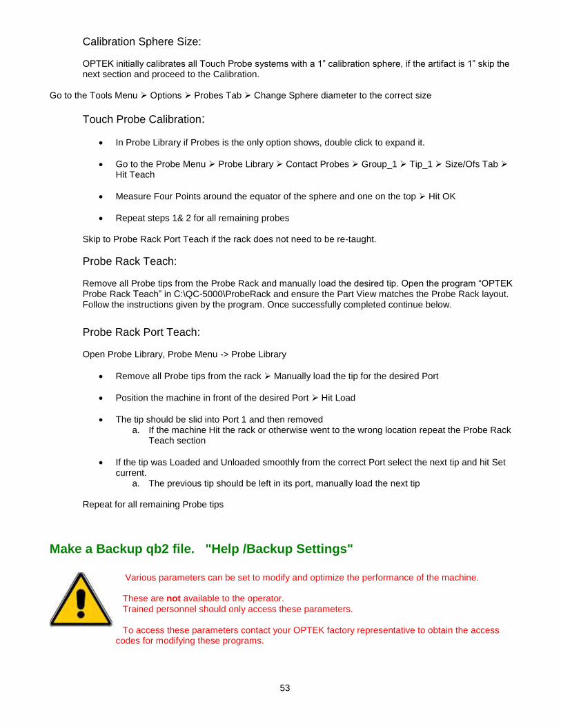
53
Calibration Sphere Size: OPTEK initially calibrates all Touch Probe systems with a 1” calibration sphere, if the artifact is 1” skip the next section and proceed to the Calibration.
Go to the Tools Menu Options Probes Tab Change Sphere diameter to the correct size
Touch Probe Calibration:
In Probe Library if Probes is the only option shows, double click to expand it.
Go to the Probe Menu Probe Library Contact Probes Group_1 Tip_1 Size/Ofs Tab Hit Teach
Measure Four Points around the equator of the sphere and one on the top Hit OK
Repeat steps 1& 2 for all remaining probes Skip to Probe Rack Port Teach if the rack does not need to be re-taught.
Probe Rack Teach: Remove all Probe tips from the Probe Rack and manually load the desired tip. Open the program “OPTEK Probe Rack Teach” in C:\QC-5000\ProbeRack and ensure the Part View matches the Probe Rack layout. Follow the instructions given by the program. Once successfully completed continue below.
Probe Rack Port Teach: Open Probe Library, Probe Menu -> Probe Library
Remove all Probe tips from the rack Manually load the tip for the desired Port
Position the machine in front of the desired Port Hit Load
The tip should be slid into Port 1 and then removed a. If the machine Hit the rack or otherwise went to the wrong location repeat the Probe Rack
Teach section
If the tip was Loaded and Unloaded smoothly from the correct Port select the next tip and hit Set current.
a. The previous tip should be left in its port, manually load the next tip
Repeat for all remaining Probe tips
Make a Backup qb2 file. "Help /Backup Settings"
Various parameters can be set to modify and optimize the performance of the machine. These are not available to the operator. Trained personnel should only access these parameters. To access these parameters contact your OPTEK factory representative to obtain the access
codes for modifying these programs.

54
Laser (Optional)
The Optimet Laser has three modes of operation, Point, Line, and Patch for each available lens. The lenses on the Optimet Laser system must be changed manually, to change the lens just unscrew it from the base of the laser. In order to set the current lens for the Optimet laser select the Probe menu Probe Library Optimet Select the Installed Lens Hit Set Current. Once the correct lens is selected, changing between VED or Laser measurement is as easy as selecting the appropriate tool.
Laser Calibration & Operation
The following procedure will require a Certified Ring Gauge. OPTEK initially calibrates all Laser systems with a 12.7mm Ring Gauge. If the gauge is 12.7mm skip the next section and proceed to the Calibration.
Ring Gauge Size:
Go to the Tools Menu Optimet settings In “Size in MM of our laser calibration artifact” Change to the Radius of the new Ring Gauge
Optimet Laser Calibration:
Ensure the VED Simple Probe is selected before continuing.
Go to the Probe Menu Probe Library Optimet
Select the lens to be taught Hit Teach a. Point, Line, and Patch are all taught at once so it makes no difference which is
selected.
Using the Simple Probe measure eight points around the Ring Gauge Hit OK
Follow the Onscreen Instructions: a. Focus the Laser on a flat surface on top of the Ring Gauge b. Move the laser to the center of the ring gauge Hit Enter Pt
Repeat steps 2 through 4 For any additional lenses
The Optimet Laser Offset is now taught and will have to be verified.
Laser Verification:
To ensure maximum accuracy the Z-Axis value may need to be adjusted slightly.
Select the Simple Probe Measure eight points around the Ring Gauge to form a circle Zero the X, Y, & Z of that circle
Select the Optimet Point Probe Focus the laser on the top of the Ring Gauge Move the laser to the center of the Gauge Hit the Check button
Measure a single point on the top of the Ring Gauge a. This point will be Used to check the Z-Axis height
Check the offset between VED and Laser. If the X or Y-Axis measurement from step 7 are off
repeat steps 2 through 4, to correct the Z-Axis continue below.
Go to the Probe Menu Probe Library Select Optimet Select the current lens

55
The Point, Line, and Patch tools will need to be corrected individually Add the Inverse of the difference between VED and Laser to the Z-Axis offset of each laser tool
Recheck Repeat steps 6 through 8 until satisfactory results are achieved
56
Chapter 6
Maintenance

57
Maintenance Through preventive maintenance, the OPTEK VideoMic VSA system will prove a benefit to your company.
General Care
The components used in the OPTEK VSA Series will provide years of service with little maintenance if the following guidelines are followed:
Keep the system clean. The working environment should be as clean, dry, and dust free as possible.
Do not take things apart.
Do not remove any covers or components from the system. Leave all screws intact. If repair is needed, contact your OPTEK representative.
Call for help.
Call OPTEK at (908) 362-6200, or contact your local representative if there are any questions or problems.
Keep the system up to date To check for the latest version of software, check the Internet at “www.metronics.com”. For the latest hardware updates, check the Internet at “www.optek.net”. If you do not have access to the Internet, fax 908-362-5966, requesting information.
Maintenance Schedule
The OPTEK Video Series requires little preventative maintenance. The key to the longevity of this machine is the same as many others, cleanliness. If a simple preventative maintenance schedule is followed, the machine will run effectively. However, if the system is not cleaned and lubricated, binding and eventual accuracy loss may result.
Maintenance Frequency
Clean exterior surfaces of equipment As needed, based on the operating environment
Clean and lubricate the rail systems Every month
Lubricate the ball screws Every six months
Clean Pneumatic Filters & Separators Every month
Clean the lens system Prior to calibration or when required
Cleaning Exterior Surfaces
Clean the painted surfaces of the equipment with a damp cloth. Use an all-purpose cleaning solution. If necessary, a protective wax may be used on the painted surfaces. The granite should be cleaned with Granite Surface Plate Cleaner (Z 212) or a compatible cleaner. This can be ordered from:
The Calibration Solution 9865 N. Alpine Road Machesney Park, IL 61115 Phone: 815-877-0880 FAX: 815-877-2062 www.thecalibrationsolution.com

58
Preventive Maintenance
Operations Technology recommends the following lubricants: 1. Lead screws - Dow Corning Lubricant 33 Extreme Low Temp Bearing Grease Medium Consistency or equivalent. 2. Granite Polish - TCS Granite Surface Plate Cleaner (Z 212) or equivalent Recommended preventive maintenance can be preformed every 1-6 months depending on the environment.
1. Check the air filter/regulators on the pneumatics panel located in the lower right hand corner of the computer bay. Check the regulator bowls for dirt and moisture and clean as required. Ensure the air source is turned OFF and residual air pressure relieved prior to bowl removal.
2. Check both the table and cantilever for dirt and debris. Clean as required using Granite Polish, TCS Granite surface plate cleaner or equivalent.
3. Lubricate the Z-axis (and Z-trac) lead screw using Dow Corning Lubricant 33 extreme low temp bearing grease medium consistency or equivalent.
4. Lubricate the Z-axis linear bearings using DuPont Krytox or equivalent.
Removal of the Hinged Glass Platen
For removal of the Hinged Glass Platen ensure the transport is positioned near the front center of the table. Remove the four Allen head cap screws holding the HGP pivot brackets to the transport. Lift the HGP off of the transport at the outside mounting brackets near where the gas spring cylinders attach.
LED lighting unit replacement
The VideoMic VSA uses a uses LED top and profile lighting. Individual LED’s are not replaceable. Contact Operations Technology for a replacement lighting module. DANGER - ENSURE ALL POWER TO THE SYSTEM IS OFF AND THE POWER CORD IS DISCONNECTED FROM THE ELECTRICAL OUTLET TO AVOID ANY INJURIES.
LED Profile Light Replacement
1. Remove / turn off power to the unit. 2. Remove the HGP and any tooling on the transport. 3. Remove the transport glass top plate by removing 16 recessed Allen head cap screws. 4. Remove the back operator station cover by removing four thumbscrews. 5. Disconnect the LED lighting module at the mini-CPC connector beneath the granite table center. 6. Remove the LED lighting module by removing four Allen head cap screws. 7. Install the new lighting module, feeding the connector wire through the hole in the granite first. Replace the
four mounting screws. 8. Connect the electrical feed at the mini-CPC connector. 9. Restore power to the unit and test the lighting module. 10. Replace the back operator’s station cover plate. 11. Remove power from the unit and reinstall the transport cover plate, HGP and any other tooling. 12. Restore the unit to operating condition and test. No calibrations are required.

59
LED Top Light Replacement
1. Remove / turn off power to the unit. 2. Remove the VideoMic VSA cover from the unit. 3. Disconnect the LED lighting module at the mini-CPC connector beneath the granite table center. 4. Remove the LED lighting module by removing two Allen head cap screws. 5. Install and fasten the new lighting module. 6. Connect the electrical feed at the mini-CPC connector near the lighting module. 7. Restore power to the unit and test the lighting module. 8. Replace the VideoMic VSA cover. 9. Restore the unit to operating condition and test. No calibrations are required.
Lubricating the rail system
The VideoMic VSA uses rails, linear roller bearings, and lead screws in the Z-axis. Proper and adequate lubrication is essential for linear motion. Poor lubrication causes a linear motion system to wear quickly and reach the service life limit prematurely. Lubricants are expected to: Lubricate the bearings to prevent seizure and minimize wear by reducing friction. Protect the metal surface of the z rails by coating the surfaces. Lubrication intervals depend on the conditions of use and the environment. The rail and bearing manufacturer recommends the system be lubricated every three to six months. OPTEK recommends cleaning and re-lubricating the rails and bearings monthly with DuPont Krytox. Lubricate the linear motion system with the same type of lubricant. Do not use or mix different lubricants.
Standard Steel Rails
To clean the rails wipe all races with lint free cloth moving the transport to expose all races in both the X and Y-axis. The lubricant recommended by the bearing and way manufacturer is any high- grade slide-way lubricant. OPTEK recommends DuPont Krytox. Use the very minimum 1/8 “dab on each race, no more. Exercise the transport system through its entire travel to ensure even distribution of Krytox.
Care of Air Bearings
Do not operate unless air pressure is applied to bearings. Air must be oil free and free of contaminants and moisture. A filtered air supply is highly recommended. ISO QUALITY CLASSES
QUALITY CLASSES
DIRT WATER OIL
Particle size in microns Pressure Dew point F (ppm Vol) at 100 psig
(including vapor) mg /cubic meter
1 0.1 -94 (0.3) 0.01
2 1.0 -40 (16) 0.1
3* 5.0 -4 (128) 1.0
4 15 +37.4 (940) 5.0
5 40 +44.6 (1240) 25
6 - +50 (1500) -
Note - OPTEK Recommends air quality of Class 3 or better.

60
Care of Guide ways
Keep guide way & bearing surfaces clean of debris & dust. Contamination with oil, coolant, or other fluids is to be avoided. Clean guide ways and bearing surfaces, when needed, with air pressure applied. Use ISOPROPYL ALCOHOL ONLY. Do not clean bearings or guide surfaces with keytones. Clean by applying alcohol to a clean dry cloth and wiping surfaces thoroughly. Allow guide surfaces to dry completely before passing bearings over cleansed area. Caution - A qualified service technician must perform all maintenance.
Cleaning the Exterior Surfaces
Clean the painted surfaces of the equipment with a damp cloth. Use an all-purpose cleaning solution. If necessary, a protective wax may be used on the painted surfaces. The granite should be cleaned with a dry cloth. Use Granite Surface Plate Cleaner (Z 212) or a compatible cleaner. This can be ordered from:
The Calibration Solution 9865 N. Alpine Road Machesney Park, IL 61115 Phone: 815-877-0880 FAX: 815-877-2062 www.thecalibrationsolution.com
Cleaning Optics
Since most solvents used to clean optics are harmful to human touch, gloves are recommended for the cleaning process. Gloves will also protect the optics from oil contamination. NOTE - OPTICS CLEANING IS NOT REQUIRED AS A PART OF A PREVENTIVE MAINTENANCE SCHEDULE. OPTICS SHOULD ONLY BE CLEANED WHEN NECESSARY. Lenses should be cleaned utilizing a lens cleaning kit including: Lint free wipes, ‘air-in-a-can’, and streak free cleaning solutions. Wiping or rubbing lenses may damage them by scratching the surface or removal of optical coatings.
Lubricants
Operations Technology recommends the following lubricants: 1. Leadscrews - Dow Corning Lubricant 33 Extreme Low Temp Bearing Grease Medium Consistency or
equivalent. 2. Linear Bearings and Rails - DuPont Krytox or equivalent. 3. Granite Polish - TCS Granite Surface Plate cleaner or equivalent.
Exploded Views:
Electronics Panel
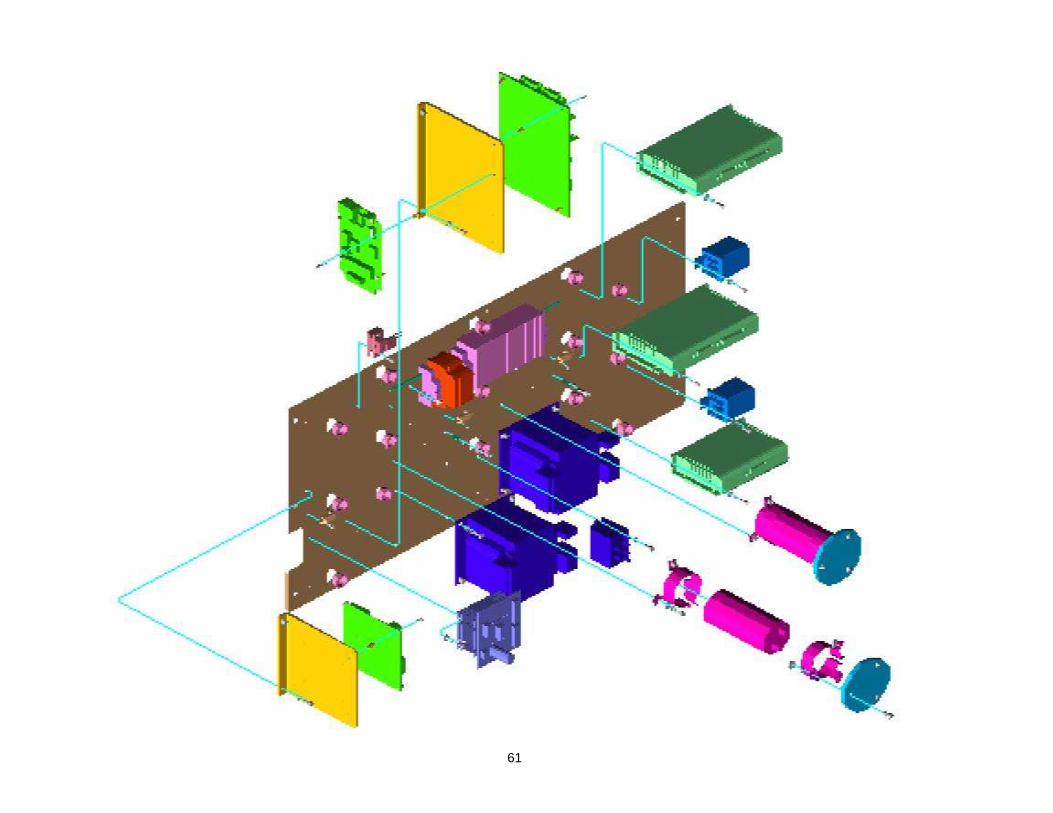
61

62

63
X-axis and Lead Screw
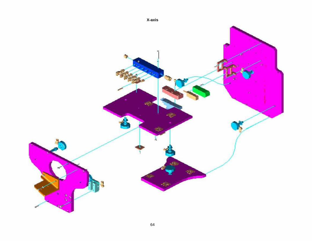
64
X-axis

65
Y-axis Transport


67
ALL MAINTENANCE IS TO BE PERFORMED BY A QUALIFIED SERVICE PERSON OR FACTORY REPRESENTATIVE.
Caution A factory representative or qualified service technician must
perform all maintenance. DANGER - Ensure All Power To The System Is Off And The Power Cord Is Disconnected From The Electrical Outlet To Avoid Any Injuries.
OPTEK SERVICE
Operations Technology, Inc Telephone: 908-362-6200 Fax: 908-362-5966 Website: www.optek.net E-Mail: [email protected]

68
Chapter 7 Warranty

69
Warranty
ITEMS COVERED BY THIS WARRANTY Standard Equipment - This is defined as all equipment, which is outlined and defined on the Operations Technology, Incorporated product lists. Special Equipment - This is defined as all options and equipment designed and constructed to fulfill a specific function utilizing unique variations in mechanics or technologies from our standard products. PERIOD OF WARRANTY Operations Technology, Incorporated warrants their products to be free of defects in material or workmanship for a period defined below commencing on the shipping date of the items covered. Standard Equipment - One year. Special Equipment - Ninety (90) days ITEMS NOT COVERED BY THIS WARRANTY The computer and associated components are covered to the extent of the original equipment manufacturer’s warranty.
LIABILITY OF WARRANTY
Operations Technology, Incorporated warrants to the original purchaser that the equipment sold under this agreement shall be free from defects in material and workmanship. Defective materials will be replaced or repaired at the discretion of Operations Technology, Incorporated. Liability will be determined by Operations Technology, Incorporated. All liability is expressly limited to said repair or replacement of defective parts, all other damages and warranties, statutory or otherwise, being expressly waived by the purchaser. This warranty is “null and void” if the equipment failure is due to negligence, accident, abuse, or improper operation. It is also nullified by tampering, altering, or unauthorized repair of subject equipment or components. This warranty does not include lamps, which are considered consumable items. The user shall return allegedly defective materials to Operations Technology, Incorporated via approved routing, charges prepaid. Upon determination of liability, Operations Technology, Incorporated will either submit a quotation for repairs or rectify the defect at no charge to the user. This warranty cannot be countermanded by the purchaser and is the only warranty relative to this transaction. No other warranty, expressed, implied or statutory, shall apply.
ALL MAINTENANCE IS TO BE PERFORMED BY A QUALIFIED SERVICE PERSON OR FACTORY REPRESENTATIVE. Turn off the power prior to working on the unit.
Service & General Care
Through preventive maintenance, the OPTEK system will prove a benefit to your company. The components used in the OPTEK Video Series will provide years of service with little maintenance if the following guidelines are followed:
Keep the system clean.
The working environment should be as clean, dry, and dust free as possible.
Do not take things apart.
Do not remove any covers or components from the system. Leave all screws intact. If repair is needed, contact your OPTEK representative.
Call for help.
Call OPTEK at (908) 362-6200, or contact your local representative if there are any questions or problems.
Keep the system up to date. To check for the latest version of software, check the Internet at “www.metronics.com”. For the latest hardware updates, check the Internet at “www.OPTEK.net”. If you do not have access to the Internet, fax 908-362-5966, requesting information.
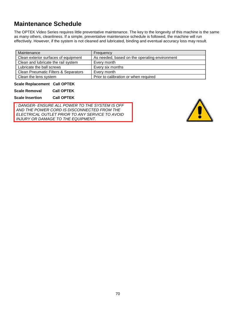
70
Maintenance Schedule
The OPTEK Video Series requires little preventative maintenance. The key to the longevity of this machine is the same as many others, cleanliness. If a simple, preventative maintenance schedule is followed, the machine will run effectively. However, if the system is not cleaned and lubricated, binding and eventual accuracy loss may result.
Maintenance Frequency
Clean exterior surfaces of equipment As needed, based on the operating environment
Clean and lubricate the rail system Every month
Lubricate the ball screws Every six months
Clean Pneumatic Filters & Separators Every month
Clean the lens system Prior to calibration or when required
Scale Replacement Call OPTEK
Scale Removal Call OPTEK
Scale Insertion Call OPTEK
: DANGER- ENSURE ALL POWER TO THE SYSTEM IS OFF AND THE POWER CORD IS DISCONNECTED FROM THE ELECTRICAL OUTLET PRIOR TO ANY SERVICE TO AVOID INJURY OR DAMAGE TO THE EQUIPMENT.