Embed Size (px)
Citation preview
1
OPERATIONS TECHNOLOGY INC.
VideoMic VSA
Operation Manual IK5000
VIDEO MEASUREMENT AND INSPECTION WORKSTATION
For: _ S/N: ______ Model ___VSA
Version G
December 2011
Operations Technology Inc. P.O. Box 408
Blairstown, NJ 07825 www.optek.net
Phone (908) 362-6200 Fax (908) 362-5966
2
VIDEO MEASUREMENT AND INSPECTION WORKSTATION. ..................................................................................... 1 Chapter 1 An Overview ........................................................................................................................................................ 4
System Overview .............................................................................................................................................................. 5 System Description ........................................................................................................................................................... 5 Camera Head Assembly ................................................................................................................................................... 6 X-Y Split-Axis Transport ................................................................................................................................................... 6 Table Assembly (Granite) ................................................................................................................................................. 6 Electronics Area ................................................................................................................................................................ 6 Control panel: ................................................................................................................................................................... 6 Computer: ......................................................................................................................................................................... 6 Front View: ........................................................................................................................................................................ 7 Software: ........................................................................................................................................................................... 7 Documentation for the OPTEK VideoMic ......................................................................................................................... 7 The Control Panel ............................................................................................................................................................. 8 Back View: ........................................................................................................................................................................ 9 Operating Principles ....................................................................................................................................................... 10
Chapter 2 Getting Started .................................................................................................................................................. 11 OPTEK VideoMic VSA Power On Procedure ................................................................................................................. 12 Homing Sequence, IK5000 ............................................................................................................................................. 12 Operational Checkout ..................................................................................................................................................... 12 Check system safety and integrity .................................................................................................................................. 12 X and Y Axis ................................................................................................................................................................... 12 Machine Zero .................................................................................................................................................................. 13 Digital Positioner ............................................................................................................................................................. 13 Tooling Fixtures or Hinged Glass Platen. ....................................................................................................................... 13 System Cooling ............................................................................................................................................................... 13 The Computer Display .................................................................................................................................................... 13 Screen Window and Video Window ............................................................................................................................... 13 Light Control Sliders ....................................................................................................................................................... 14 Quadrant Lighting ........................................................................................................................................................... 14 HGP and Lighting ........................................................................................................................................................... 15
Chapter 4 IK5000 Calibration ............................................................................................................................................. 16 Calibration of the VideoMic VSA in IK5000 .................................................................................................................... 17 Calibration Procedure Overview ..................................................................................................................................... 17 Adjustments to the Camera System ............................................................................................................................... 17 Calibration Procedure ..................................................................................................................................................... 17 Adjusting the Camera Squareness ................................................................................................................................. 17 Camera Rotation Correction ........................................................................................................................................... 17 Pixel Calibration .............................................................................................................................................................. 18 IK5000 Calibration procedure for the Probe Library ....................................................................................................... 19 Probe Library: Mag Tab .................................................................................................................................................. 19 Probe Library - VED Probes ........................................................................................................................................... 19 Probe Library: Autofocus Tab ......................................................................................................................................... 20 Probe Library: Resolution Tab ........................................................................................................................................ 20 Camera Calibration- Camera SKEW .............................................................................................................................. 20 Probe Library-Offset Tab ................................................................................................................................................ 21
Chapter 5 Troubleshooting ................................................................................................................................................. 22 Startup Troubleshooting Checklist .................................................................................................................................. 23 Problems and possible causes ....................................................................................................................................... 23 Other Symptoms and possible causes ........................................................................................................................... 23 Restoring Your System to a Previous State ................................................................................................................... 24 Symptoms ....................................................................................................................................................................... 24 IK5000 Core Files ........................................................................................................................................................... 24 Back-up Your System ..................................................................................................................................................... 25
Chapter 6 Maintenance ...................................................................................................................................................... 26 Maintenance ................................................................................................................................................................... 27 General Care .................................................................................................................................................................. 27 Maintenance Schedule ................................................................................................................................................... 27 Cleaning Exterior Surfaces ............................................................................................................................................. 27 Preventive Maintenance ................................................................................................................................................. 28
3
Removal of the Hinged Glass Platen .............................................................................................................................. 28 LED lighting unit replacement ......................................................................................................................................... 28 LED Profile Light Replacement....................................................................................................................................... 28 LED Top Light Replacement........................................................................................................................................... 29 Lubricating the rail system (Z-Axis) ................................................................................................................................ 29 Standard Steel Rails (Z-Axis) ......................................................................................................................................... 29 Care of Air Bearings ....................................................................................................................................................... 29 Care of Guide ways ........................................................................................................................................................ 30 Cleaning the Exterior Surfaces ....................................................................................................................................... 30 Cleaning Optics .............................................................................................................................................................. 30 Lubricants ....................................................................................................................................................................... 30 OPTEK SERVICE ........................................................................................................................................................... 30
Chapter 7 Warranty ............................................................................................................................................................ 31 Warranty ......................................................................................................................................................................... 32 LIABILITY OF WARRANTY ............................................................................................................................................ 32 Service & General Care .................................................................................................................................................. 32 Maintenance Schedule ................................................................................................................................................... 33

4
Chapter 1
An Overview

5
The VideoMic VSA
System Overview
In response to the ever-increasing demands placed on industry to improve the quality, decrease the size, and increase the density of a given product, the OPTEK systems have evolved. The VideoMic VSA systems are the latest response to industry’s move toward more compact products while imposing greater throughput and accuracy requirements. These products, many not heard of ten years ago, must be measured, inspected, and repaired in a production environment. The OPTEK VideoMic VSA offers solutions for these challenging manufacturing problems. Like earlier OPTEK video systems, which offer the ability to automatically measure objects using programmable optical magnification and lighting changes, the OPTEK VideoMic VSA allows for sensitive feature detection in challenging situations. Superior performance is accomplished through user directed optimization of contrast, video edge detection, pixel analysis, and accurate transport movement. The VideoMic VSA offers advanced features such as: Balanced Linear Motors, High Resolution Linear Scales, Modified Bearings and Support Systems, A Hi-Resolution LCD Monitor, more Powerful Frame Grabber, Full-size Keyboard, Adjustable Operator Station. The combined effect of these improvements is: smoother, more stable, and quieter operation, higher accuracy, more rapid and capable sample processing, increased component reliability with decreased maintenance. Once optimal test methods are determined, they are saved in a measurement program for automatic execution. The systems utilize a Pentium computer with a high-resolution flat panel color monitor operating in a Windows XP environment. The icon driven inspection and measurement process is simple and intuitive. Measurement programs are created quickly by either recording measurements made on a sample part or by importing CAD (computer aided design) data and selecting the features to be checked. User customized reporting of tolerance compared data, and pass / fail information can be linked (locally or via network) to SPC (Statistical Process Control) software, spreadsheets, databases, or simply printed. The OPTEK measurement systems work best in a clean, thermally stable, vibration free environment. If possible, always ensure the very best situation for your inspection and measurement machines.
The OPTEK VideoMic VSA
System Description
The OPTEK system allows movement in six directions. Left and right is referred to as the X Axis. Back and forth is referred to as the Y-Axis. Up and Down is referred to as the Z-Axis. Measurements can be made in all three axes.
The unit must be positioned so the rear of the machine is accessible, in order to operate the Main Disconnect if needed. The unit must be plugged into an outlet with a protective grounding terminal. Caution: A Qualified Service Technician must perform any required maintenance.
6
Parts Description:
Camera Head Assembly
Z Axis Camera transport
Programmable Zoom Lens
Light Sources: Top light-ring for surface features, On-Axis illumination for indented features. Optional Z-Trac lighting for difficult situations.
X-Y Split-Axis Transport
Hinged Glass Platen used for securing samples for viewing
Interlock safety device to stop all motion.
Optional "Tooling Fences" to secure samples to the stage in a reproducible fashion.
Table Assembly (Granite)
Bottom light for profile work
X / Y Transport Stage
Electronics Area
Electronics boards
Power supplies and amplifiers
Fuses
Rear power switch/circuit breaker
Control panel:
Power switches
Emergency "off "lockout
Joystick for X, Y, and Z
Digital Positioner
Data entry buttons
Computer:
Network Card
Frame Grabber Board
X, Y, and Z Axis board with onboard light, I/O and programmable zoom controller.
7
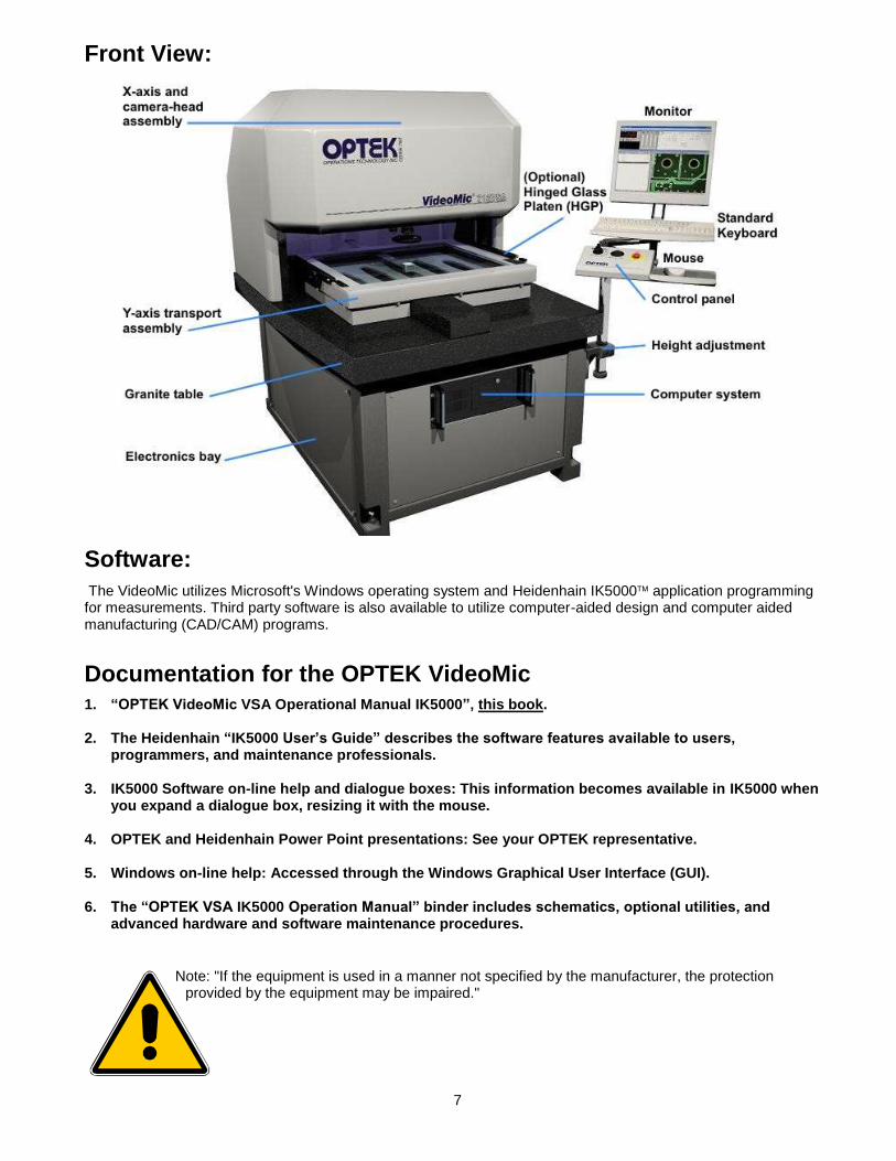
Front View:
Software:
The VideoMic utilizes Microsoft's Windows operating system and Heidenhain IK5000 application programming for measurements. Third party software is also available to utilize computer-aided design and computer aided manufacturing (CAD/CAM) programs.
Documentation for the OPTEK VideoMic
1. “OPTEK VideoMic VSA Operational Manual IK5000”, this book. 2. The Heidenhain “IK5000 User’s Guide” describes the software features available to users,
programmers, and maintenance professionals. 3. IK5000 Software on-line help and dialogue boxes: This information becomes available in IK5000 when
you expand a dialogue box, resizing it with the mouse. 4. OPTEK and Heidenhain Power Point presentations: See your OPTEK representative. 5. Windows on-line help: Accessed through the Windows Graphical User Interface (GUI). 6. The “OPTEK VSA IK5000 Operation Manual” binder includes schematics, optional utilities, and
advanced hardware and software maintenance procedures.
Note: "If the equipment is used in a manner not specified by the manufacturer, the protection provided by the equipment may be impaired."
8
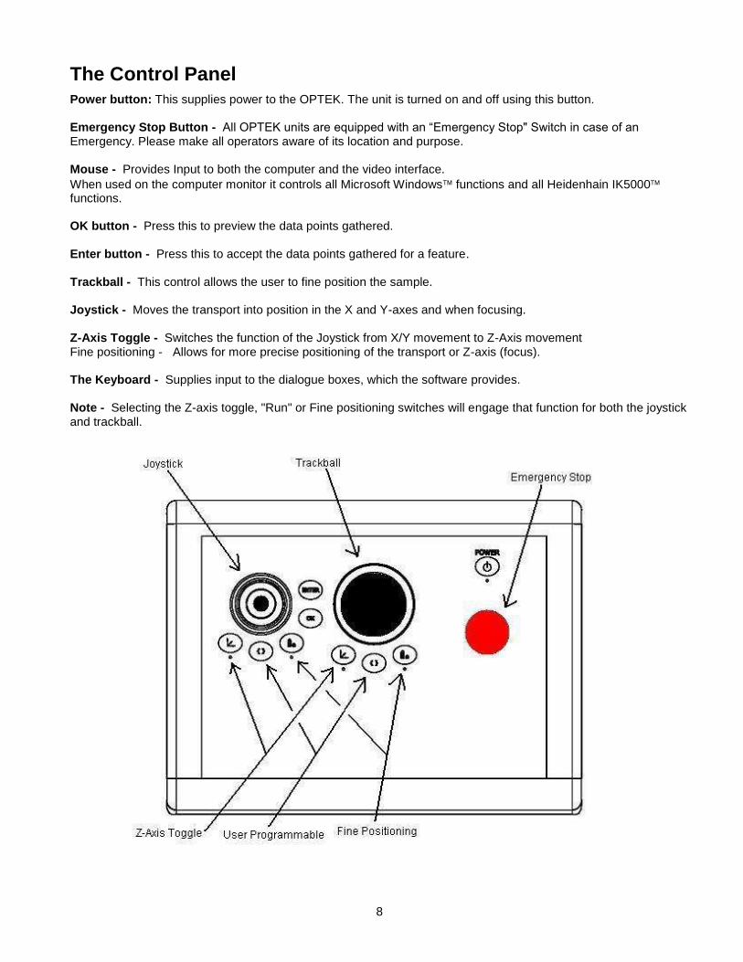
The Control Panel
Power button: This supplies power to the OPTEK. The unit is turned on and off using this button. Emergency Stop Button - All OPTEK units are equipped with an “Emergency Stop" Switch in case of an Emergency. Please make all operators aware of its location and purpose. Mouse - Provides Input to both the computer and the video interface.
When used on the computer monitor it controls all Microsoft Windows functions and all Heidenhain IK5000 functions. OK button - Press this to preview the data points gathered. Enter button - Press this to accept the data points gathered for a feature. Trackball - This control allows the user to fine position the sample. Joystick - Moves the transport into position in the X and Y-axes and when focusing. Z-Axis Toggle - Switches the function of the Joystick from X/Y movement to Z-Axis movement Fine positioning - Allows for more precise positioning of the transport or Z-axis (focus). The Keyboard - Supplies input to the dialogue boxes, which the software provides. Note - Selecting the Z-axis toggle, "Run" or Fine positioning switches will engage that function for both the joystick and trackball.

9
Power requirements - 120 VAC 60 Hz or 220 VAC, 50 HZ, 5.0 Amp single phase. Since OPTEK machines are sent world wide, connectors for your machine for power requirements are not supplied. See a qualified electrician for hookup according to local safety codes. Air Requirements - Clean, dry compressed air 3 CFM (85 Liters/min), at 110-120 PSI (7-8.25 bar), regulator adjusted to 80 PSI.
The OPTEK VideoMic VSA should be mounted level, within about .005"/foot, for best performance.
Caution - For power installation see a qualified service technician to obtain a power connection and approved hardware.
Caution - The unit must be positioned so it is easy to operate the Main Disconnect.
Caution - The unit must be plugged in to an outlet with a protective grounding terminal.
Caution - A qualified service technician must perform any required maintenance.
Back View:
10
Operating Principles
The use of the VideoMic depends on five main principles. User Programmability - over movement, focus, magnification, lighting, data acquisition tools, and reporting. Automating these tasks eliminates operator error and speeds throughput. Accurate Positioning - of samples obtained from high acceleration, linear motors, and high accuracy scales to determine position. Path optimization may improve throughput. Non-Linear Error Correction (NLEC) - This software feature allows any errors detected in the measurement system to be corrected automatically. The entire measurement area is mapped and compensated for inherent mechanical errors. Video Edge Detection (VED) - A user programmable feature, which allows the choice of how the software sees a feature. Setting the threshold strength and the VED method provides great flexibility in the types of features, which can be measured. Control over the image from the camera and frame grabber - The IK5000 software and lighting may be used to manipulate the image to enhance weak features and image processing software library functions for the frame grabber take advantage of the video enhancement capabilities. These five main concepts, combined with other principals make the OPTEK VideoMic a teachable, automatic, and accurate measuring device.
Caution: Operation of this equipment assumes some basic knowledge of computers
and MS-Windows software. If you are not familiar with these computer terms please read this manual completely before you power up the OPTEK VideoMic workstation.

11
Chapter 2
Getting Started
12
OPTEK VideoMic VSA Power On Procedure
Ensure compressed air is being provided at the back of the VideoMic VSA
At the console: 1. Ensure the X and Y axis are positioned in the center of travel. 2. Ensure the “Emergency Stop” button is in the up position. Press the “Power” On button. 3. If necessary, turn on the monitor. Use the individual power button for this. 4. If the PC is not on, turn on the PC and follow the on screen instructions. 5. Ensure the HGP is lowered and no objects are in the light interrupt path. 6. Ensure all Control Panel LED's are off (Fine position & Z axis toggle). 7. Move the transport by hand in all directions. It should move freely. 8. Start IK5000 software using the icon. 9. The VideoMic VSA will automatically proceed through a “homing” sequence. When completed the
transport should be positioned with the camera lens near the center of the glass platen. 10. Conduct a test of the Operator’s controls - joystick, trackball, interlocks, etc.
Caution Note - The transport cannot move with the HGP open. Be certain the HGP is closed while setting Machine Zero.
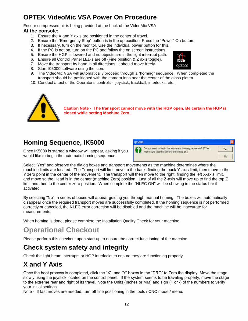
Homing Sequence, IK5000
Once IK5000 is started a window will appear, asking if you would like to begin the automatic homing sequence. Select "Yes" and observe the dialog boxes and transport movements as the machine determines where the machine limits are located. The Transport will first move to the back, finding the back Y-axis limit, then move to the Y zero point in the center of the movement. The transport will then move to the right, finding the left X-axis limit, and move so the Head is in the center (machine Zero) position. Last of all the Z-axis will move up to find the top Z limit and then to the center zero position. When complete the "NLEC ON" will be showing in the status bar if activated. By selecting "No", a series of boxes will appear guiding you through manual homing. The boxes will automatically disappear once the required transport moves are successfully completed. If the homing sequence is not performed correctly or canceled, the NLEC error correction will be disabled and the machine will be inaccurate for measurements. When homing is done, please complete the Installation Quality Check for your machine.
Operational Checkout Please perform this checkout upon start up to ensure the correct functioning of the machine.
Check system safety and integrity
Check the light beam interrupts or HGP interlocks to ensure they are functioning properly.
X and Y Axis
Once the boot process is completed, click the “X”, and “Y” boxes in the “DRO” to Zero the display. Move the stage slowly using the joystick located on the control panel. If the system seems to be traveling properly, move the stage to the extreme rear and right of its travel. Note the Units (Inches or MM) and sign (+ or -) of the numbers to verify your initial settings. Note - If fast moves are needed, turn off fine positioning in the tools / CNC mode / menu.
13
Machine Zero
Machine zero is critical, as it is the reference for the calibration system. The IK5000 will go through a homing process immediately on startup (see Homing Sequence) or, using the mouse, choose the "Set Machine Zero" from the "Datum" menu. This position for X, Y, and Z is the machine zero position. After this process, it is possible to have non-zero numbers in the display. This is OK.
Digital Positioner
Move the Digital Positioner, (trackball). This allows for fine movement. Watch the Digital Read Out (DRO) on the monitor to ensure the trackball is moving one of the axes. If the numbers move in the DRO relative to the axis being moved, the trackball is functioning correctly. Note also the display resolution. This should match the resolution of the encoder scales.
Tooling Fixtures or Hinged Glass Platen.
Check to see if any tooling fixtures are mounted and secure. If a pneumatic system is used, actuate this through its cycle and back.
System Cooling
Verify that the fan is working on the system. The fan is located on the back near the power switches, on the electrical bay side of the unit. The fan will turn on immediately when the green “Power” switch is depressed. There are one or more fans integral to the computer. They are of the automatic type and may or may not be on at that time.
The Computer Display
Screen Window and Video Window
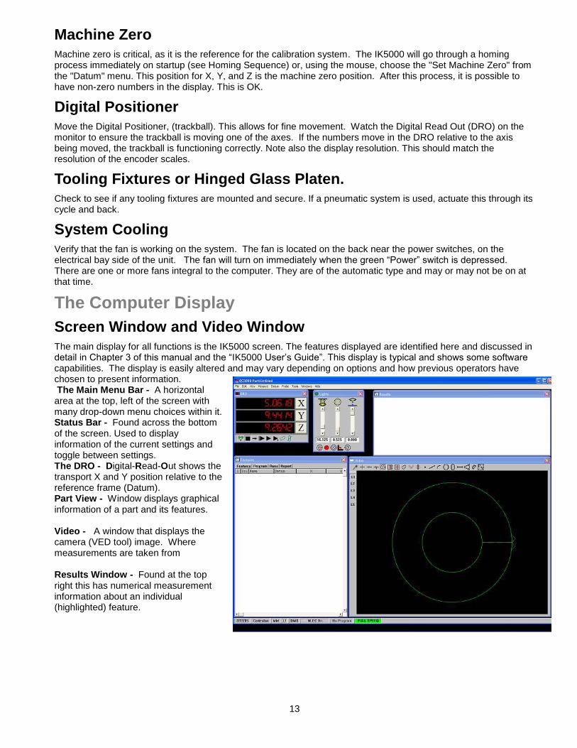
The main display for all functions is the IK5000 screen. The features displayed are identified here and discussed in detail in Chapter 3 of this manual and the “IK5000 User’s Guide”. This display is typical and shows some software capabilities. The display is easily altered and may vary depending on options and how previous operators have chosen to present information. The Main Menu Bar - A horizontal area at the top, left of the screen with many drop-down menu choices within it. Status Bar - Found across the bottom of the screen. Used to display information of the current settings and toggle between settings. The DRO - Digital-Read-Out shows the transport X and Y position relative to the reference frame (Datum). Part View - Window displays graphical information of a part and its features. Video - A window that displays the camera (VED tool) image. Where measurements are taken from Results Window - Found at the top right this has numerical measurement information about an individual (highlighted) feature.

14
Feature Stamp - A separate pane opened from a box in the upper left of the “Results Window”. It contains graphical information about the selected feature(s) and distribution of measurement points. Measure Toolbar - Used to measure and construct features. Buttons correspond to items on the “Measure” menu. View - The view toolbar is used to adjust the part view window. Layer control and Toolbars can also be accessed here. Buttons correspond to items on the “View” menu. View Rotator - Changes the display angle of the part view and feature stamp. Tolerance toolbar - Used for performing tolerances on selected features. Tolerances include: run-out, concentricity, parallelism, true positions, etc. Datum - This toolbar is used for establishing various Datum (Zeroing) operations and reference frames. Program: A toolbar used to access programming functions. Buttons correspond to items on the “Tools” menu. Feature (List) - Found as a tab in the “Program” window, this describes the measured features. Program (List) - Found as a tab in the “Program” window, this shows the part program listing. This is a brief introduction to the software display. Amplifying information on each of the above may be found in the “IK5000 User’s Manual” or later in this manual. There is an excellent interactive online manual for IK5000. It is highly recommended that all operators spend some time with the CD-ROM.
Light Control Sliders
The image quality varies with the type of sample being tested and the options chosen in the light control window. Once the OPTEK is turned on and IK5000 is running you must establish the initial settings for the material you are to measure. Note - Although we see colors by the nature of the process, video boards see a monochrome image consisting of black to white and grays in between. All image enhancements are made by making adjustments to the gray scale, which affect the image that the camera sees. The controls have icons for the following optional lighting variations:
Ring Light or Z-Trac (optional) source intensity.
On Axis Lighting source intensity (optional).
Bottom light source intensity
Elevation of the Z-Trac assembly (optional).
Quadrant lighting, selection and intensity (optional).
Quadrant Lighting
Quadrant lighting is available as an option. The icons provide for the lighting of features from the sides for edge detection on highly variable subjects. The quadrants may be turned on or off by clicking on the quadrant position in the icon.
Front Left Right Rear

15
HGP and Lighting
The presence of the Hinged Glass Platen above a sample will affect the behavior of light from the sources above the sample. Keep this in mind when testing light solutions.

16
Chapter 4
Calibration
17
Calibration of the VideoMic VSA in IK5000
Calibration Procedure Overview
A Complete calibration consists of both optical calibrations and calibration of the movement system. Optical: Check parfocality and parcentricity first. Mechanical squareness and camera rotation adjustments follow and then software adjustments to the imaging system using the probe library. Movement: The transport movement is then determined and incorporated into the calibration using NLEC (Non Linear Error Correction).
Adjustments to the Camera System
Camera Rotation - A mechanical adjustment. Pixel calibration - Software compensation. Camera Rotation Calibration - Software compensation. Camera Offset - For multiple Magnification Systems
Calibration Procedure Do squareness or camera rotation first. Pixel cal can be approximate at this point
Adjusting the Camera Squareness
(A Mechanical Rotation which is only required if the machine or camera system is moved.) The next step in the alignment process is to ensure the camera is square to the X-axis travel. With a large crosshair on the video monitor, place a sharp image all the way to the left side of the screen just touching the horizontal line of the crosshair. Move the image to the right side of the screen with the joystick. The object should follow the line. If the does not follow the crosshair line, loosen the two camera mount set screws (Also used in adjusting Parfocality) and rotate the camera until the image stays on the line from left to right. Tighten the setscrews when the image touches the line from left to right.
Camera Rotation Correction
(Software Alignment) Position a dot resting tangential to the crosshair tool horizontal centerline, on the Video window at the left side of the field of view. From the CNC toolbar choose Axis Lock Tools \ General \ Password \ Enter the security code. Choose: Probe \ Probe library. Select “VED” from the left side window and “Camera” from the right side. Select the “Orientation” tab to adjust Camera Skew. Click the Teach button. A calibration circle tool will appear on the Video monitor. An instruction box will appear on the right. Follow these instructions to complete the Camera Rotation Correction. This completes the Camera Rotation Correction. Exit this window by pressing OK.
18
Pixel Calibration
Assuring that the feature measures at the correct size. All measurements are performed by calculating pixels. These pixels have a set value that is determined through a simple calibration process. If the pixels are not calibrated, any measurements made will be incorrect. The pixel calibration is based upon the Calibration Slide. The standard Calibration Slide shipped with the system is for reference only. This is not a traceable item. If a traceable Calibration Slide is needed, please contact your OPTEK representative or contact Operations Technology, Incorporated for more information.
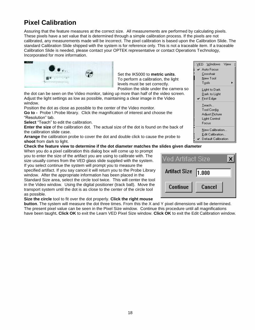
Set the IK5000 to metric units. To perform a calibration, the light levels must be set correctly. Position the slide under the camera so
the dot can be seen on the Video monitor, taking up more than half of the video screen. Adjust the light settings as low as possible, maintaining a clear image in the Video window. Position the dot as close as possible to the center of the Video monitor. Go to - Probe \ Probe library. Click the magnification of interest and choose the “Resolution” tab. Select “Teach” to edit the calibration. Enter the size of the calibration dot. The actual size of the dot is found on the back of the calibration slide case. Arrange the calibration probe to cover the dot and double click to cause the probe to shoot from dark to light. Check the feature view to determine if the dot diameter matches the slides given diameter When you do a pixel calibration this dialog box will come up to prompt you to enter the size of the artifact you are using to calibrate with. The size usually comes from the VED glass slide supplied with the system. If you select continue the system will prompt you to measure the specified artifact. If you say cancel it will return you to the Probe Library window. After the appropriate information has been placed in the Standard Size area, select the circle tool twice. This will center the tool in the Video window. Using the digital positioner (track ball). Move the transport system until the dot is as close to the center of the circle tool as possible. Size the circle tool to fit over the dot properly. Click the right mouse button. The system will measure the dot three times. From this the X and Y pixel dimensions will be determined. The present pixel value can be seen in the Pixel Size window. Continue this procedure until all magnifications have been taught. Click OK to exit the Learn VED Pixel Size window. Click OK to exit the Edit Calibration window.
19
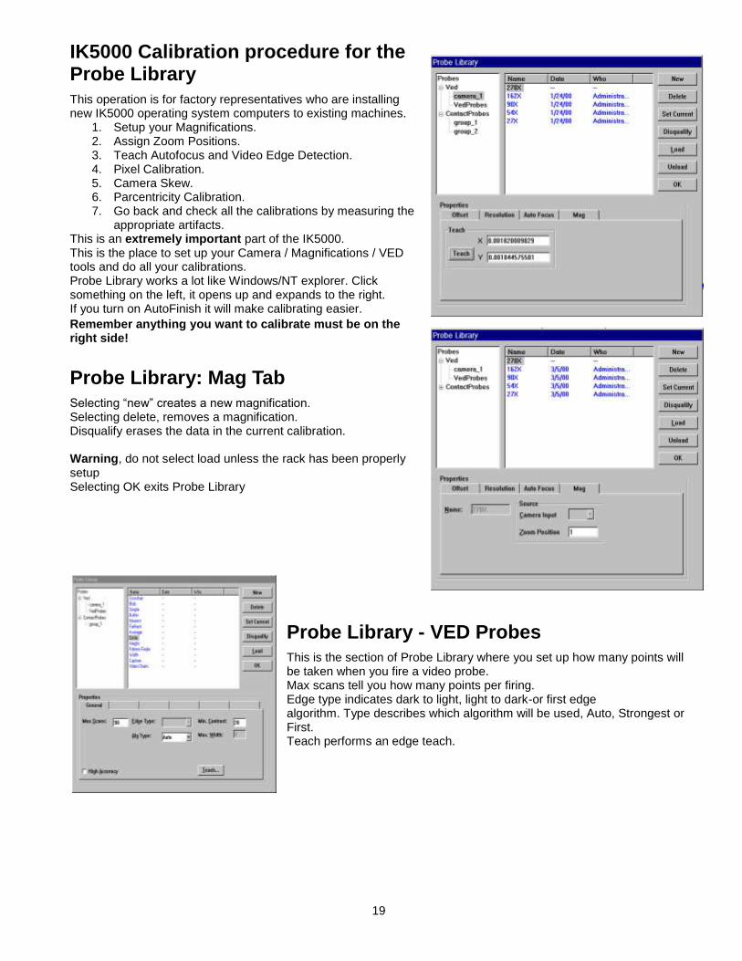
IK5000 Calibration procedure for the Probe Library
This operation is for factory representatives who are installing new IK5000 operating system computers to existing machines.
1. Setup your Magnifications. 2. Assign Zoom Positions. 3. Teach Autofocus and Video Edge Detection. 4. Pixel Calibration. 5. Camera Skew. 6. Parcentricity Calibration. 7. Go back and check all the calibrations by measuring the
appropriate artifacts. This is an extremely important part of the IK5000. This is the place to set up your Camera / Magnifications / VED tools and do all your calibrations. Probe Library works a lot like Windows/NT explorer. Click something on the left, it opens up and expands to the right. If you turn on AutoFinish it will make calibrating easier.
Remember anything you want to calibrate must be on the right side!
Probe Library: Mag Tab
Selecting “new” creates a new magnification. Selecting delete, removes a magnification. Disqualify erases the data in the current calibration. Warning, do not select load unless the rack has been properly setup Selecting OK exits Probe Library
Probe Library - VED Probes
This is the section of Probe Library where you set up how many points will be taken when you fire a video probe. Max scans tell you how many points per firing. Edge type indicates dark to light, light to dark-or first edge algorithm. Type describes which algorithm will be used, Auto, Strongest or First. Teach performs an edge teach.

20
Probe Library: Autofocus Tab
This is where you teach the AUTOFOCUS range of each magnification. You must do a TEACH for each Magnification. You can also set a search Distance manually. If you teach from here, you can use most VED Tools. Remember a safe distance is in the up direction. Make sure your “Z” is counting positive in the up direction.
Probe Library: Resolution Tab
Select teach to do your Video Pixel Calibration. You MUST calibrate each magnification. Notice the size of a pixel at each magnification. Remember we do sub-pixel edge detection. The IK5000’s edge detection is far superior to the QC4000. The edge detection is extremely sensitive in low light settings.
Camera Calibration- Camera SKEW
This is the section of Probe Library where you do your Camera Calibration. If you click on “Teach” Probe Library walks you through doing a camera Skew calibration. If your camera image is backwards or opposite you can change the Orientation here. Remember to make this one of your first calibrations.

21
Probe Library-Offset Tab
This frame shows the offset from magnification MedHigh to the master mag High. These offset are also known as parcentricity and parfocality. If you click on teach the system will walk you through the calibration. You should start this procedure at MedHigh. Notice reference is not checked. Only the master probe (HIGH) in the group is checked. The same calibration needs to be done for each of the other magnifications, except High, which is the Master Probe in this group.

22
Chapter 5
Troubleshooting

23
Startup Troubleshooting Checklist This is a very short list to help if simple oversights occur. For extensive troubleshooting, consult your supervisor and other documentation provided.
Problems and possible causes
The system does not turn on. Is the red, emergency stop button in the up position? Is the power cord plugged in? Is the line voltage correct (115 VSAC or 220 VAC)? The monitor does not work. Is the monitor turned on? Does it show an image? Is the video cable plugged in? The computer does not turn on. Is the computer power button pressed in? Is the line voltage correct (115 VSAC or 220 VAC)? Is the power cord plugged in? The printer does not work. Is the printer plugged in and turned on? Is the paper loaded? Is the data cable plugged in? The stage moves by itself. Are the cables in the control panel plugged in? Is the DRO operating correctly? Computer connections terminated properly? The transport does not move in one or two directions Did the Homing sequence complete correctly? The digital positioner (trackball) does not work. Is the digital positioner turned on in the software? Choose “Tools/ CNC … / Digital Positioner Make sure the X and the Y ”Enable” boxes are marked. The stage will not move beyond a certain point Did the machine zero point get set correctly? From the Datum Menu, choose Set Machine Zero. Follow the on-screen prompts. Cannot see an Image Are the lights adjusted properly? Do you have an object in the field of view?
Other Symptoms and possible causes
Before making any changes, use the restore method inside IK5000. In truth, all problems can be reduced to two types, Software problems, and hardware problems. Try to determine if the hardware or the software is then cause of your symptoms, and narrow it down from there. Hardware problems are either breakage or alignment problems. Software problems can be thought of as corrupt or missing files. Software can be corrupted by electrical interference, spikes, bad shutdowns, or operator error.
24
Restoring Your System to a Previous State
With the Supervisor's password entered, GO TO "Help / Restore Settings". Select the time or file you want to revert to.
Symptoms
Noise - In Transport Drive systems. Is it in the X or Y system only? Humming Linear motor Tuning issue Scraping Scale or reader head misalignment Grinding Mechanical part loose, worn, or misaligned. Movement problem:
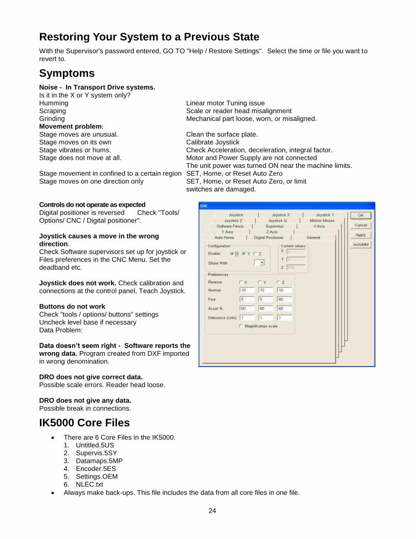
Stage moves are unusual. Clean the surface plate. Stage moves on its own Calibrate Joystick Stage vibrates or hums. Check Acceleration, deceleration, integral factor. Stage does not move at all. Motor and Power Supply are not connected The unit power was turned ON near the machine limits. Stage movement in confined to a certain region SET, Home, or Reset Auto Zero Stage moves on one direction only SET, Home, or Reset Auto Zero, or limit switches are damaged. Controls do not operate as expected Digital positioner is reversed Check "Tools/ Options/ CNC / Digital positioner". Joystick causes a move in the wrong direction. Check Software supervisors set up for joystick or Files preferences in the CNC Menu. Set the deadband etc. Joystick does not work. Check calibration and connections at the control panel, Teach Joystick. Buttons do not work Check "tools / options/ buttons" settings Uncheck level base if necessary Data Problem: Data doesn’t seem right - Software reports the wrong data. Program created from DXF imported in wrong denomination. DRO does not give correct data. Possible scale errors. Reader head loose. DRO does not give any data. Possible break in connections.
IK5000 Core Files
There are 6 Core Files in the IK5000. 1. Untitled.5US 2. Supervis.5SY 3. Datamaps.5MP 4. Encoder.5ES 5. Settings.OEM 6. NLEC.txt
Always make back-ups. This file includes the data from all core files in one file.

25
Back-up Your System
The IK5000 software makes periodic automatic backups. GOTO "Help / Backup Settings". Once named the file will be saved into the "IK5000\Backups" folder. Backups (.qb2 files) and any important "part" files should also be copied to disc or other removable media and retained in a safe location.

26
Chapter 6
Maintenance

27
Maintenance Through preventive maintenance, the OPTEK VideoMic VSA system will prove a benefit to your company.
General Care
The components used in the OPTEK VSA Series will provide years of service with little maintenance if the following guidelines are followed:
Keep the system clean. The working environment should be as clean, dry, and dust free as possible.
Do not take things apart.
Do not remove any covers or components from the system. Leave all screws intact. If repair is needed, contact your OPTEK representative.
Call for help.
Call OPTEK at (908) 362-6200, or contact your local representative if there are any questions or problems.
Keep the system up to date To check for the latest version of software, check the Internet at “www.Heidenhain.com”. For the latest hardware updates, check the Internet at “www.optek.net”. If you do not have access to the Internet, fax 908-362-5966, requesting information.
Maintenance Schedule
The OPTEK Video Series requires little preventative maintenance. The key to the longevity of this machine is the same as many others, cleanliness. If a simple preventative maintenance schedule is followed, the machine will run effectively. However, if the system is not cleaned and lubricated, binding and eventual accuracy loss may result.
Maintenance Frequency
Clean exterior surfaces of equipment As needed, based on the operating environment
Clean and lubricate the rail systems Every month
Lubricate the ball screws Every six months
Clean Pneumatic Filters & Separators Every month
Clean the lens system Prior to calibration or when required
Cleaning Exterior Surfaces
Clean the painted surfaces of the equipment with a damp cloth. Use an all-purpose cleaning solution. If necessary, a protective wax may be used on the painted surfaces. The granite should be cleaned with Granite Surface Plate Cleaner (Z 212) or a compatible cleaner. This can be ordered from:
The Calibration Solution 9865 N. Alpine Road Machesney Park, IL 61115 Phone: 815-877-0880 FAX: 815-877-2062 www.thecalibrationsolution.com

28
Preventive Maintenance
Operations Technology recommends the following lubricants: 1. Lead screws - Dow Corning Lubricant 33 Extreme Low Temp Bearing Grease Medium Consistency or equivalent. 2. Granite Polish - TCS Granite Surface Plate Cleaner (Z 212) or equivalent Recommended preventive maintenance can be preformed every 1-6 months depending on the environment.
1. Check the air filter/regulators on the pneumatics panel located in the lower right hand corner of the computer bay. Check the regulator bowls for dirt and moisture and clean as required. Ensure the air source is turned OFF and residual air pressure relieved prior to bowl removal.
2. Check both the table and cantilever for dirt and debris. Clean as required using Granite Polish, TCS Granite surface plate cleaner or equivalent.
3. Lubricate the Z-axis (and Z-trac) lead screw using Dow Corning Lubricant 33 extreme low temp bearing grease medium consistency or equivalent.
4. Lubricate the Z-axis linear bearings using Dupont Krytox or equivalent.
Removal of the Hinged Glass Platen
For removal of the Hinged Glass Platen ensure the transport is positioned near the front center of the table. Remove the four Allen head cap screws holding the HGP pivot brackets to the transport. Lift the HGP off of the transport at the outside mounting brackets near where the gas spring cylinders attach.
LED lighting unit replacement
The VideoMic VSA uses a uses LED top and profile lighting. Individual LED’s are not replaceable. Contact Operations Technology for a replacement lighting module. DANGER - ENSURE ALL POWER TO THE SYSTEM IS OFF AND THE POWER CORD IS DISCONNECTED FROM THE ELECTRICAL OUTLET TO AVOID ANY INJURIES.
LED Profile Light Replacement
1. Remove / turn off power to the unit. 2. Remove the HGP and any tooling on the transport. 3. Remove the transport glass top plate by removing 16 recessed Allen head cap screws. 4. Remove the back operator station cover by removing four thumbscrews. 5. Disconnect the LED lighting module at the mini-CPC connector beneath the granite table center. 6. Remove the LED lighting module by removing four Allen head cap screws. 7. Install the new lighting module, feeding the connector wire through the hole in the granite first. Replace
the four mounting screws. 8. Connect the electrical feed at the mini-CPC connector. 9. Restore power to the unit and test the lighting module. 10. Replace the back operator’s station cover plate. 11. Remove power from the unit and reinstall the transport cover plate, HGP and any other tooling. 12. Restore the unit to operating condition and test. No calibrations are required.
29
LED Top Light Replacement
1. Remove / turn off power to the unit. 2. Remove the VideoMic VSA cover from the unit. 3. Disconnect the LED lighting module at the mini-CPC connector beneath the granite table center. 4. Remove the LED lighting module by removing two Allen head cap screws. 5. Install and fasten the new lighting module. 6. Connect the electrical feed at the mini-CPC connector near the lighting module. 7. Restore power to the unit and test the lighting module. 8. Replace the VideoMic VSA cover. 9. Restore the unit to operating condition and test. No calibrations are required.
Lubricating the rail system (Z-Axis)
The VideoMic VSA uses rails, linear roller bearings, and lead screws in the Z-axis. Proper and adequate lubrication is essential for linear motion. Poor lubrication causes a linear motion system to wear quickly and reach the service life limit prematurely. Lubricants are expected to: Lubricate the bearings to prevent seizure and minimize wear by reducing friction. Protect the metal surface of the z rails by coating the surfaces. Lubrication intervals depend on the conditions of use and the environment. The rail and bearing manufacturer recommends the system be lubricated every three to six months. OPTEK recommends cleaning and re-lubricating the rails and bearings monthly with Dupont Krytox. Lubricate the linear motion system with the same type of lubricant. Do not use or mix different lubricants.
Standard Steel Rails (Z-Axis)
To clean the rails wipe all races with lint free cloth moving the transport to expose all races in both the X and Y-axis. The lubricant recommended by the bearing and way manufacturer is any high- grade slide-way lubricant. OPTEK recommends Dupont Krytox. Use the very minimum 1/8 “dab on each race, no more. Exercise the transport system through its entire travel to ensure even distribution of Krytox.
Care of Air Bearings
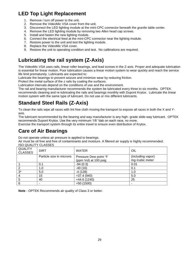
Do not operate unless air pressure is applied to bearings. Air must be oil free and free of contaminants and moisture. A filtered air supply is highly recommended. ISO QUALITY CLASSES
QUALITY CLASSES
DIRT WATER OIL
Particle size in microns Pressure Dew point F (ppm Vol) at 100 psig
(including vapor) mg /cubic meter
1 0.1 -94 (0.3) 0.01
2 1.0 -40 (16) 0.1
3* 5.0 -4 (128) 1.0
4 15 +37.4 (940) 5.0
5 40 +44.6 (1240) 25
6 - +50 (1500) -
Note - OPTEK Recommends air quality of Class 3 or better.
30
Care of Guide ways
Keep guide way & bearing surfaces clean of debris & dust. Contamination with oil, coolant, or other fluids is to be avoided. Clean guide ways and bearing surfaces, when needed, with air pressure applied. Use ISOPROPYL ALCOHOL ONLY. Do not clean bearings or guide surfaces with keytones. Clean by applying alcohol to a clean dry cloth and wiping surfaces thoroughly. Allow guide surfaces to dry completely before passing bearings over cleansed area. Caution - A qualified service technician must perform all maintenance.
Cleaning the Exterior Surfaces
Clean the painted surfaces of the equipment with a damp cloth. Use an all-purpose cleaning solution. If necessary, a protective wax may be used on the painted surfaces. The granite should be cleaned with a dry cloth. Use Granite Surface Plate Cleaner (Z 212) or a compatible cleaner. This can be ordered from:
The Calibration Solution 9865 N. Alpine Road Machesney Park, IL 61115 Phone: 815-877-0880 FAX: 815-877-2062 www.thecalibrationsolution.com
Cleaning Optics
Since most solvents used to clean optics are harmful to human touch, gloves are recommended for the cleaning process. Gloves will also protect the optics from oil contamination. NOTE - OPTICS CLEANING IS NOT REQUIRED AS A PART OF A PREVENTIVE MAINTENANCE SCHEDULE. OPTICS SHOULD ONLY BE CLEANED WHEN NECESSARY. Lenses should be cleaned utilizing a lens cleaning kit including: Lint free wipes, ‘air-in-a-can’, and streak free cleaning solutions. Wiping or rubbing lenses may damage them by scratching the surface or removal of optical coatings.
Lubricants
Operations Technology recommends the following lubricants: 1. Leadscrews - Dow Corning Lubricant 33 Extreme Low Temp Bearing Grease Medium Consistency or
equivalent. 2. Linear Bearings and Rails - Dupont Krytox or equivalent. 3. Granite Polish - TCS Granite Surface Plate cleaner or equivalent. ALL MAINTENANCE IS TO BE PERFORMED BY A QUALIFIED SERVICE PERSON OR FACTORY REPRESENTATIVE.
Caution A factory representative or qualified service technician must
perform all maintenance. DANGER - Ensure All Power To The System Is Off And The Power Cord Is Disconnected From The Electrical Outlet To Avoid Any Injuries.
OPTEK SERVICE
Operations Technology, Inc Telephone: 908-362-6200 Fax: 908-362-5966 Website: www.optek.net E-Mail: [email protected]

31
Chapter 7 Warranty

32
Warranty
ITEMS COVERED BY THIS WARRANTY Standard Equipment - This is defined as all equipment, which is outlined and defined on the Operations Technology, Incorporated product lists. Special Equipment - This is defined as all options and equipment designed and constructed to fulfill a specific function utilizing unique variations in mechanics or technologies from our standard products. PERIOD OF WARRANTY Operations Technology, Incorporated warrants their products to be free of defects in material or workmanship for a period defined below commencing on the shipping date of the items covered. Standard Equipment - One year. Special Equipment - Ninety (90) days ITEMS NOT COVERED BY THIS WARRANTY The computer and associated components are covered to the extent of the original equipment manufacturer’s warranty.
LIABILITY OF WARRANTY
Operations Technology, Incorporated warrants to the original purchaser that the equipment sold under this agreement shall be free from defects in material and workmanship. Defective materials will be replaced or repaired at the discretion of Operations Technology, Incorporated. Liability will be determined by Operations Technology, Incorporated. All liability is expressly limited to said repair or replacement of defective parts, all other damages and warranties, statutory or otherwise, being expressly waived by the purchaser. This warranty is “null and void” if the equipment failure is due to negligence, accident, abuse, or improper operation. It is also nullified by tampering, altering, or unauthorized repair of subject equipment or components. This warranty does not include lamps, which are considered consumable items. The user shall return allegedly defective materials to Operations Technology, Incorporated via approved routing, charges prepaid. Upon determination of liability, Operations Technology, Incorporated will either submit a quotation for repairs or rectify the defect at no charge to the user. This warranty cannot be countermanded by the purchaser and is the only warranty relative to this transaction. No other warranty, expressed, implied or statutory, shall apply.
ALL MAINTENANCE IS TO BE PERFORMED BY A QUALIFIED SERVICE PERSON OR FACTORY REPRESENTATIVE. Turn off the power prior to working on the unit.
Service & General Care
Through preventive maintenance, the OPTEK system will prove a benefit to your company. The components used in the OPTEK Video Series will provide years of service with little maintenance if the following guidelines are followed:
Keep the system clean.
The working environment should be as clean, dry, and dust free as possible.
Do not take things apart.
Do not remove any covers or components from the system. Leave all screws intact. If repair is needed, contact your OPTEK representative.
Call for help.
Call OPTEK at (908) 362-6200, or contact your local representative if there are any questions or problems.
Keep the system up to date. To check for the latest version of software, check the Internet at “www.Heidenhain.com”. For the latest hardware updates, check the Internet at “www.OPTEK.net”. If you do not have access to the Internet, fax 908-362-5966, requesting information.
33
Maintenance Schedule
The OPTEK Video Series requires little preventative maintenance. The key to the longevity of this machine is the same as many others, cleanliness. If a simple, preventative maintenance schedule is followed, the machine will run effectively. However, if the system is not cleaned and lubricated, binding and eventual accuracy loss may result.
Maintenance Frequency
Clean exterior surfaces of equipment As needed, based on the operating environment
Clean and lubricate the rail system Every month
Lubricate the ball screws Every six months
Clean Pneumatic Filters & Separators Every month
Clean the lens system Prior to calibration or when required
Scale Replacement Call OPTEK
Scale Removal Call OPTEK
Scale Insertion Call OPTEK
: DANGER- ENSURE ALL POWER TO THE SYSTEM IS OFF AND THE POWER CORD IS DISCONNECTED FROM THE ELECTRICAL OUTLET PRIOR TO ANY SERVICE TO AVOID INJURY OR DAMAGE TO THE EQUIPMENT.

34
Appendix A Programming The Accelus / Junis
Amplifiers

35

36
Appendix B Touch Probe Calibration

37
First determine if the Probe Rack needs to be re-taught, select a new probe tip. While changing tips, if the machine hits the rack or otherwise goes to an incorrect location the rack will need to be re-taught. Manually remove all tips from the rack and unload all tips. If there is no movement, or a message instructing to manually load the tip, load the desired tip by hand and continue. In Probe Library on the left, Double Click the Probes Group if no sub categories are shown
Unload Probe Tips:
1. Go to the Probe Menu Click Probe Library 2. Select ContactProbes Group_1 Tip_1 Unload (Button above OK) 3. Repeat step 2 for all remaining probes
Calibration Sphere Size: OPTEK initially calibrates all Touch Probe systems with a 1” calibration sphere, if the artifact is 1” skip the next section and proceed to the Calibration.
1. Go to the Tools Menu Options Probes Tab Change Sphere diameter to the correct size
Touch Probe Calibration: In Probe Library if Probes is the only option shows, double click to expand it.
1. Go to the Probe Menu Probe Library ContactProbes Group_1 Tip_1 Size/Ofs Tab Hit Teach 2. Measure Four Points around the equator of the sphere and one on the top Hit OK 3. Repeat steps 1& 2 for all remaining probes
Skip to Probe Rack Port Teach if the rack does not need to be re-taught.
Probe Rack Teach: Remove all Probe tips from the Probe Rack and manually load the desired tip. Open the program “OPTEK ProbeRack Teach” in C:\QC-5000\ProbeRack and ensure the Part View matches the Probe Rack layout. Follow the instructions given by the program. Once successfully completed continue below.
Probe Rack Port Teach: Open Probe Library, Probe Menu -> Probe Library
1. Remove all Probe tips from the rack Manually load the tip for the desired Port 2. Position the machine in front of the desired Port Hit Load 3. The tip should be slid into Port 1 and then removed
a. If the machine Hit the rack or otherwise went to the wrong location repeat the Probe Rack Teach section
4. If the tip was Loaded, and Unloaded smoothly from the correct Port select the next tip and hit Set current.
a. The previous tip should be left in its port, manually load the next tip 5. Repeat for all remaining Probe tips