Embed Size (px)
Citation preview

Victoreen®
451B & 451B-DE-SI Ion Chamber Survey Meter
Operators Manual
September 2009 Manual No. 1021101000 Rev. 10 ©2006, 2007, 2009 Fluke Corporation, All rights reserved. Printed in U.S.A. All product names are trademarks of their respective companies

Fluke Biomedical 6045 Cochran Road Cleveland, Ohio 44139 440.498.2564 www.flukebiomedical.com

Table of Contents Section 1: General Information................................................................................... 1-1
1.1 Introduction .................................................................................................. 1-1 1.2 Features....................................................................................................... 1-2 1.3 Specifications............................................................................................... 1-2 1.4 Receiving Inspection.................................................................................... 1-5
Section 2: Operation.................................................................................................... 2-1 2.1 External Controls ......................................................................................... 2-1 2.2 Self-Test ...................................................................................................... 2-2 2.3 Installation.................................................................................................... 2-2 2.4 Optional Check Source Use (450 UCS)....................................................... 2-3
Section 3: Theory Of Operation....................................................................... 3-1 3.1 Introduction .................................................................................................. 3-1 3.2 Firmware...................................................................................................... 3-3
Section 4: Maintenance .................................................................................. 4-1 4.1 Introduction .................................................................................................. 4-1 4.2 Preventive Maintenance .............................................................................. 4-1 4.3 Routine Cleaning ......................................................................................... 4-1 4.4 Storage ........................................................................................................ 4-1 4.5 Battery Replacement ................................................................................... 4-2 4.6 Ion Chamber Window Replacement ............................................................ 4-2 4.7 Outer Mylar Window Replacement .............................................................. 4-3 4.8 HV Battery Board and Desiccant Replacement ........................................... 4-3 4.9 Lithium Cell Replacement ............................................................................ 4-4 4.10 Replacement Parts Information ................................................................... 4-5 4.11 Recalibration and Service Information ......................................................... 4-5
Section 5: Troubleshooting ............................................................................ 5-1 5.1 Troubleshooting Precautions ....................................................................... 5-1 5.2 Troubleshooting ........................................................................................... 5-1
i


General InformationIntroduction 1
1-1
Section 1 General Information
1.1 Introduction The Model 451B Ion Chamber Survey Meters are hand-held, battery operated units designed to measure alpha above 7.5 MeV, beta above 100 keV, and gamma & x-ray radiation above 7 keV, using the latest CMOS and LCD technology. The 451B case is constructed of high strength ABS plastic. A gasket and desiccant pack seal moisture out of the unit and provides a cushion for the internal components. The readout consists of a 2 1/2-digit liquid crystal display and a 100 segment analog bar graph. The bar graph contains a zero segment and twenty groups of five segments each. A permanent scale is located on the display screen. The major divisions of the scale indicate the units corresponding to the range that the meter is measuring. Units of measurement are displayed next to the 2 1/2-digit display. LOW BAT and FREEZE will appear on the display when the instrument is operating in these modes. External controls consist of an ON/OFF button and a MODE button. The unit is auto-ranging and auto-zeroing. The auto-on circuit for the backlight is enabled when twilight conditions occur. The 451B has an audio alarm that can be set by the user. Two nine-volt batteries, located in the back of the instrument, provide over 200 hours of continuous operation. A 440 mg/cm2 phenolic shield is provided as a beta shield. The shield also serves as an equilibrium thickness for photon measurements & protects the Mylar window.

Victoreen 451B & 451B-DE-SI Owners Manual
1-2
1.2 Features
1.2.1 Overrange Rate If the instantaneous radiation rate measured by the Model 451B exceeds 50 R/h (0.5 Sv/h), the 'R' in R/h or the 'Sv' in Sv/h displayed will blink to notify the user that the radiation field exceeds the measuring capability of the instrument. Also, a potential error in the integrated radiation value may exist due to this condition. The blinking will stop when the integrated value is cleared.
1.2.2 Low Battery Indicator There are about 6 hours of operation remaining when the LOW BATTERY indicator first becomes visible. When the LOW BATTERY indicator blinks, there is less than one hour of operation remaining. These times are for 2 batteries installed and from the first occurrences of these indications. If the instrument is turned off during a low battery condition, the batteries will recover somewhat, but time of operation remaining will be less.
1.2.3 Audio Alarm The audio alarm set points are set using the RS-232 COMM port connected to a computer along with the associated software. The audio alarm set point is set in increments of 1% full scale. That is from 1% to 100% of full scale. The “A” command in the menu allows access to the scale and percent set point. The alarm will sound when readings reach or exceed the set point.
1.2.4 Integrate Mode The Integrate Mode allows the Model 451B to display the integrated exposure. Exposures are accumulated up to 999 R (9.99 Sv).
1.2.5 Freeze Mode The Freeze Mode will move a “bar” on the bar graph display to show the user the peak value, and will lock on the maximum range. The unit will continue to read and display current readings.
1.2.6 Auto-on Backlight The Model 451B is equipped with a backlight which automatically turns on when ambient light drops below a predetermined level. The backlight will turn off when the ambient light exceeds the predetermined level, which is factory set.
1.3 Specifications Radiation Detected Alpha above 7.5 MeV, beta above 100 keV, gamma above 7 keV
Operating Ranges 451B: 0 to 5 mR/h, 0 to 50 mR/h, 0 to 500 mR/h, 0 to 5 R/h, 0 to 50 R/h
451B-DE-SI: 0 to 50 µSv/h, 0 to 500 µSv/h, 0 to 5 mSv/h, 0 to 50 mSv/h, 0 to 500 mSv/h
Accuracy ± 10% of reading between 10% and 100% of full-scale indication on any range, exclusive of energy response (Calibration source is 137Cs)

General InformationSpecifications 1
1-3
Detector 349 cc volume air ionization chamber; phenolic chamber wall 246 mg/cm2. Chamber window is composed of 6.6 mg/cm2 Mylar. A coating of graphite has been applied to the walls to make them conductive. The collection potential is -63 Volts. The Chamber is vented through the desiccant
451B-DE-SI: In order to achieve energy response consistent with measurements of H*(10) as required by ICR4-47, aluminum has been added to the back wall, 38% of the side wall area, and to the beta slide. With the Beta Shield open, the 451B can measure skin dose at H* (0.07), and Deep Dose H* (10) with the Beta shield closed.
Warm-Up Time Less than one minute for initial operation
Response Time Time measured from 10% to 90% of final value for a step increase/decrease in radiation rate such that a range change does not occur:
451B: 0 to 5 mR/h, range: 8 seconds. 0 to 50 mR/h, range: 2.5 seconds. 0 to 500 mR/h range: 2 seconds. 0 to 5 R/h, range: 2 seconds. 0 to 50 R/h, range: 2 seconds
451B-DE-SI: 0 to 50 µSv/h, range: 8 seconds. 0 to 500 µSv/h, range: 2.5 seconds. 0 to 5 mSv/h, range: 2 seconds. 0 to 50 mSv/h, range: 2 seconds. 0 to 500 mSv/h range: 2 seconds
NOTE: Instantaneous exposure rate is limited to 50 R/h (0.5 Sv/h), including but not limited to a pulsed field.
Precision Within 10% of reading
Readout Liquid Crystal Display: Contains an analog bar graph with a permanent scale on the display and a 2 1/2 digit display. Analog Display: The bar graph consists of 100 segments, 2 1/2 inches long; the scale has five major divisions; the appropriate value for the operating range of the instrument will appear below the scale. Digital Display: The digital display is 2 1/2 digits followed by a significant zero digit depending on the operating range of the instrument. The leading 1/2 digit is blank, or a “1” or a “0” for clarity. Units of measure appear to the right of the digital display. Appropriate multipliers also appear on the display units: As indicated under Range, programmable in R/h or Sv/h
External Controls ON/OFF button, MODE button.
Automatic Features Ranging and zeroing are fully automatic.
Environment Operating Temperature Range: -20º to 50ºC Relative Humidity Range: 0 to 95% non-condensing Geotropism: Less than 1% Dimensions 8 5/8 (l) x 4 1/2 (w) x 8 in (h) (21.6 x 11.3 x 20 cm)
Weight Approximately 2 lb, 9 oz (1.16 kg)
Batteries Two 9-volt batteries provide over 200 hours continuous operation. Three lithium cells provide chamber bias voltage of 63 V (10 year life expectancy)
Audio Alarm Set through communication programs. Setting at 1% increments, 1% to 100% full scale
Temperature Sensor A temperature sensor in the 451B-DE-SI is used to adjust for offset drift due to temperature. Readings are not corrected for changes in air density due to pressure and temperature

Victoreen 451B & 451B-DE-SI Owners Manual
1-4
Check Source Model number 450 UCS, allows user to check for proper instrument operation. Gives a nominal reading of 0.4 mR/h (4 µ Sv/h)
Model 451B-DE-SI Typical Energy DependenceDose equivalent units were determined using conversion coefficients at H*(10), found in ICRU 47,
April, 1992.
0.8
0.9
1
1.1
1.2
1.3
1.4
1.5
1.6
1.7
1.8
10 100 1000 10000
Energy (keV)
Indi
cate
d / A
ctua
l
Side
Slide - Closed
Slide - Open
Model 451B Typical Energy Dependence
0.2
0.3
0.4
0.5
0.6
0.7
0.8
0.9
1
1.1
1.2
10 100 1000 10000Effective (keV)
Indi
cate
d/A
ctua
l
Side
Slide - Closed
Slide - Open
General InformationReceiving Inspection 1
1-5
1.4 Receiving Inspection Upon receipt of the unit:
1. Check the shipping cartons(s) and their contents for in-shipment damage. If damage is evident, file a claim with the carrier and contact Fluke Biomedical, Radiation Management Services Repair Coordinator at 440.498.2564 or 800.850.4606 immediately.
2. Check that all items listed on the packing slip are present and in good condition. If any items are missing or damaged, contact Fluke Biomedical, Radiation Management Services Repair Coordinator at 440.498.2564 or 800.850.4606 immediately.


OperationExternal Controls 2
2-1
Section 2 Operation
2.1 External Controls There are two external controls on the survey meter: an ON/OFF button and a MODE button.
2.1.1 ON/OFF Button Press the ON/OFF button to turn the unit on. All the elements in the display turn on and the microprocessor runs through an initialization procedure. Part of the procedure includes reading the calibration coefficients stored in EEPROM. If an EEPROM read error occurs, an error code (E1) will be displayed at power-on and unity calibration coefficients will be used.
The bar graph and digital display will show a reading that decreases as the instrument stabilizes. The initial reading usually starts in the 50 R/h (50 mSv/h) range and decreases through the lower ranges to a reading of less than 0.5 mR/h (5 µSv/h) within 40 seconds. When the elements in the display turn off, with the exception of those necessary for normal operation, the user can begin the measurement process.
Note: Background fluctuations may occur (less than 0.5 mR/h (5 µSv/h)) returning to the original reading typically in less than 3 seconds.
2.1.2 Mode Button To configure the MODE button to the opposite function without the RS-232 connection, use the following procedure:
1. Turn the unit off. 2. Press the MODE button. 3. Turn the unit on while continuing to press the MODE button. 4. Release the MODE button when the display is in the “all elements on” condition. 5. Use the MODE button to toggle the instrument between the rate mode and the newly selected
freeze or integrate mode.
2.1.3 Integrate Mode The Integrate mode is operational 30 seconds after the instrument is turned on and all of the time after that. However the integrated exposure can only be displayed when the MODE button has been configured as a toggle to display exposure rate/integrated exposure. If the MODE button is pressed within the 30-second initialization period of the unit, the display will read “0.”
When integration starts, “0.0 µR (0.00 µ Sv)” will be displayed. Toggle MODE to read exposure rate as required.
To reset the integration display, toggle the display from the Rate mode to the Integrate mode. Keep the MODE button pressed for about 5 seconds. The display will clear, and then read “0.0 µR (0.00 µ Sv).” Exposures are accumulated up to 999 R (9.99 Sv).

Victoreen 451B & 451B-DE-SI Owners Manual
2-2
2.1.4 Freeze Mode When configured to select the Freeze mode, the MODE button acts as a toggle switch. Press the button until FREEZE appears on the display. Operation in the Freeze mode gives the user a constant reference of the highest exposure rate obtained from the time the freeze function is initialized. The highest reading will appear as a single bar on the bar graph. The current reading will continue to be displayed on the digital display and the bar graph. If a measurement is obtained which exceeds the freeze bar reading, the freeze bar will move to the higher measurement point. The operating range of the 451B remains locked on the highest range attained during the Freeze mode so that the scale and the multiplier remain the same.
For example, assume the scale units appear as 10, 20, 30, 40, 50, and the freeze bar is at 47 mR/h on the bar graph. If the 451B then measures a radiation field of 120 mR/h, the scale units will change to 100, 200, 300, 400, 500, and the freeze bar will appear on the graph at 120 mR/h. If the survey meter measurement goes below 100 mR/h, the units on the scale will not change until the survey meter is taken out of the freeze mode. However, the digital display will continue to show the current reading. The survey meter will operate in the Freeze mode until the user toggles the MODE button to return to the normal operating mode.
NOTE
If a measurement is obtained which causes a range change higher than the alarm set point range, the alarm will sound and continue to sound until the freeze mode is disabled.
2.2 Self-Test When the 451B survey meter is first turned on, it runs through a functional self test procedure. During this self-test, the firmware version of the unit is displayed, along with the HI or LO chamber bias.
WARNING
If chamber bias is LO, the instrument can’t measure high radiation rates accurately. Service to the instrument is required.
If the unit passes the self-test, it will go into the normal operating mode. If the unit fails the self-test it will remain locked with the firmware revision displayed. Consult a Fluke Biomedical, Radiation Management Repair Coordinator for corrective action.
2.3 Installation The Model 451B periodically tests for mark signal at its RS-232 port. When an RS-232 signal is detected, the Model 451B sends test signals using its sending device and, if RS-232 is present and operational, the survey meter will enter into the communications mode. The 451B display will clear and the letters “CO” will be displayed as an indication that the unit is in the communications mode.

OperationInstallation 2
2-3
The 451B is compatible with a CRT or printing terminal having a standard RS-232 connector and a 1200-baud rate. A computer with a modem or terminal emulator may be used in place of the terminal. The terminal or computer should be set up for 1200 baud, 7 data bits, no parity bit, and 1 stop bit.
1. Connect the 9 pin female connector to an active communication serial port. 2. When “CO” appears on the 451B display, press the computer or terminal space bar twice.
If the Model 451 displays the “CO” message but there is no response at the terminal after pressing the space bar twice, perform the following tests:
1. Be sure that the 451B and terminal are properly connected via the RS-232 cable. If there is still a problem, consult the Fluke Biomedical, Radiation Management Services Repair Coordinator for further instructions.
2.4 Optional Check Source Use (450 UCS)
WARNING The check source contains radioactive materials, used for the verification of survey meter operation. Use care in the handling and storage.
To check the Model 451B, perform the following:
1. Turn instrument on and allow one minute to warm up. 2. Open the beta shield. 3. Place the check source flat against the end window. 4. Check for a nominal reading of 0.4 mR/h (4 uSv/h).


Theory of OperationIntroduction 3
3-1
Section 3 Theory Of Operation
3.1 Introduction
WARNING This unit contains lithium cells with a potential voltage of 63 V on the battery assembly. Use care in handling this assembly during removal and installation. Damage to the instrument or bodily harm may result.
NOTE
The user is cautioned about indiscriminately opening and disassembling the instrument. The high impedance circuits of the ion chamber are easily contaminated with grease and dirt that produce electrical leakage. Complete Assembly/Disassembly instructions are available in the Maintenance Section of this manual.
The Model 451B is an air ionization chamber instrument calibrated in exposure rate units of roentgens/hour (or Sieverts/hour) for gamma and x-ray in the energy range of 20 keV to 2 MeV through the sliding Phenolic shield. It can also be used for x-ray in the energy range of 7 keV to 30 keV with the sliding shield open. The Model 451B responds to, but is not calibrated for, beta radiation, with the slide open. Beta energies that can be measured are above 100 keV. The two thin Mylar windows have a combined density thickness of 6.6 mg/cm2. The 451B also responds to alpha radiation above 7.5 MeV.
The liquid crystal display shows the radiation rate in digital and analog form with the range multiplier values also showing on the scale. It is a lightweight electronic device that requires the computational capabilities of a microprocessor to make it operate. It functions in a multiplex mode called quadruplex. This mode uses four backplanes to accommodate the 128 elements of the display.
The microprocessor performs data collection, averaging, and multiplication by stored calibration factors, range changing, and battery check functions, in addition to driving the LCD. Between computational periods, it “sleeps” in a low power mode to conserve battery power. The microprocessor reads stored information from an electrically erasable memory, EEPROM, which is used by the program for calibration and display units. The EEPROM will retain stored data when the instrument is OFF or when the batteries are removed. Data can be entered into the EEPROM using the RS-232 port.

Victoreen 451B & 451B-DE-SI Owners Manual
3-2
63 V collection voltage for the ion chamber is obtained from lithium cells that have a 10-year life. All internal power for the instrument is supplied by the 9 V batteries, accessible from the rear of the instrument.
The digital and bar graph displays read directly. The bar graph display update periods are listed in Table 3-1. The digital display updates at one second intervals nearest the current bar display update. The bar graph and digits display do not always show the same reading because the bar graph is faster than the digital update. It is more convenient to watch the bar graph when the reading is changing quickly and to read the value of a slowly changing or static reading by looking at the digital display.
The bar graph display is a digital presentation, programmed to appear as a linear analog meter display. It is also referred to as the analog display throughout this manual.
Bar graph display update periods
Range Update Period 50 R/h (500 mSv/h) 0.05 second 5 R/h (50 mSv/h) 0.1 second 500 mR/h (5 mSv/h) 0.1 second 50 mR/h (500 µSv/h) 0.15 second 5 mR/h (50 µSv/h) 0.25 second
There are 20 bars between each major division. The numerical values of the five major divisions change appropriately for the range in which the instrument is operating. For instance, the first major division would have the numeric value of 1, 10, or 100. The minor divisions are worth 0.05, 0.5 or 5. The incremental nature of both the digital reading and the analog bar graph provide greater accuracy for reading in different portions of the scale. For example, on the 0-5 mR/h (0-50 µSv/h) range, with a digital reading of 2.0 and above, the analog bar graph can be read more accurately than the digital display. Below a digital reading of 2.0, the digital display is more accurate because it consists of three significant digits. The stated precision of the digital display is accurate only above a reading of 0.20 on the 0-5 mR (0-50 Sv) scale.
The same analysis applies to all the other ranges because the number of significant digits or active bar elements are independent of the position of the decimal point or the units multiplier.
NOTE
There is a small hysteresis built into the range changing circuit so that the instrument does not keep changing scales if the reading is at the threshold of range change. It is important in calibration of the instrument that the calibration coefficients track from range to range because an oscillatory condition can occur if the calibration on a given range is low and the coefficient for the next more sensitive range is high.
In addition to FREEZE, the other message that can appear on the display is LOW BAT. When the LOW BAT message appears, the batteries should be changed within one hour.
The display will indicate HI for good chamber voltage bias condition.

Theory of OperationFirmware 3
3-3
3.2 Firmware The program in the 451 ROM is proprietary to Fluke Biomedical, Radiation Management Services. The firmware version appears in the digital part of the LCD display (prior to the “all elements on” display) when the instrument is turned on. The firmware program consists of three main parts: operation, communication, and monitoring.
The operation portion of the firmware performs all of the control functions needed to read and control the electrometer and range change amplifier, calculate radiation rate, and display the calculated values on the LCD Display. In addition, the measured data are smoothed and displayed in an exponential manner with time that simulates the rise and fall time of an ordinary meter display. Range changing is performed automatically. If a large increase in signal is detected, the range changing skips to higher ranges bypassing exponential rise with time to get to the new reading quickly. The instrument continually integrates the detected radiation signal and saves the accumulated amount that may be read by the operator at any time. The operator may also reset the integration process.


MaintenanceIntroduction 4
4-1
Section 4 Maintenance
4.1 Introduction Very little maintenance is required for the survey meter, but some periodic attention may be necessary, especially if the instrument is used in harsh industrial conditions.
4.2 Preventive Maintenance Very little maintenance is required for the survey meter, but some periodic attention may be necessary, especially if the instrument is used in harsh industrial conditions. The desiccant must be renewed and replaced periodically (see 4.8).
NOTE
Install fresh batteries prior to performing any calibration on this instrument.
4.3 Routine Cleaning Do not immerse the Model 451B or 451B-DE-SI. The unit is not waterproof; liquid could damage the circuits. The unit should be kept clean and free from dirt and contamination. The unit may be cleaned by wiping with a damp cloth using any commercially available cleaning or decontaminating agent.
4.4 Storage If the unit is to be stored prior to use, pack it in the original container, if possible, and store in an environment free of corrosive materials, fluctuations in temperature and humidity, vibration or shock. The instrument should be stored with the two 9 Volt batteries removed. Prior to use, check the condition of the desiccant. A blue color indicates that the desiccant is good, while a pink color indicates the need to replace/regenerate.
Victoreen 451B & 451B-DE-SI Owners Manual
4-2
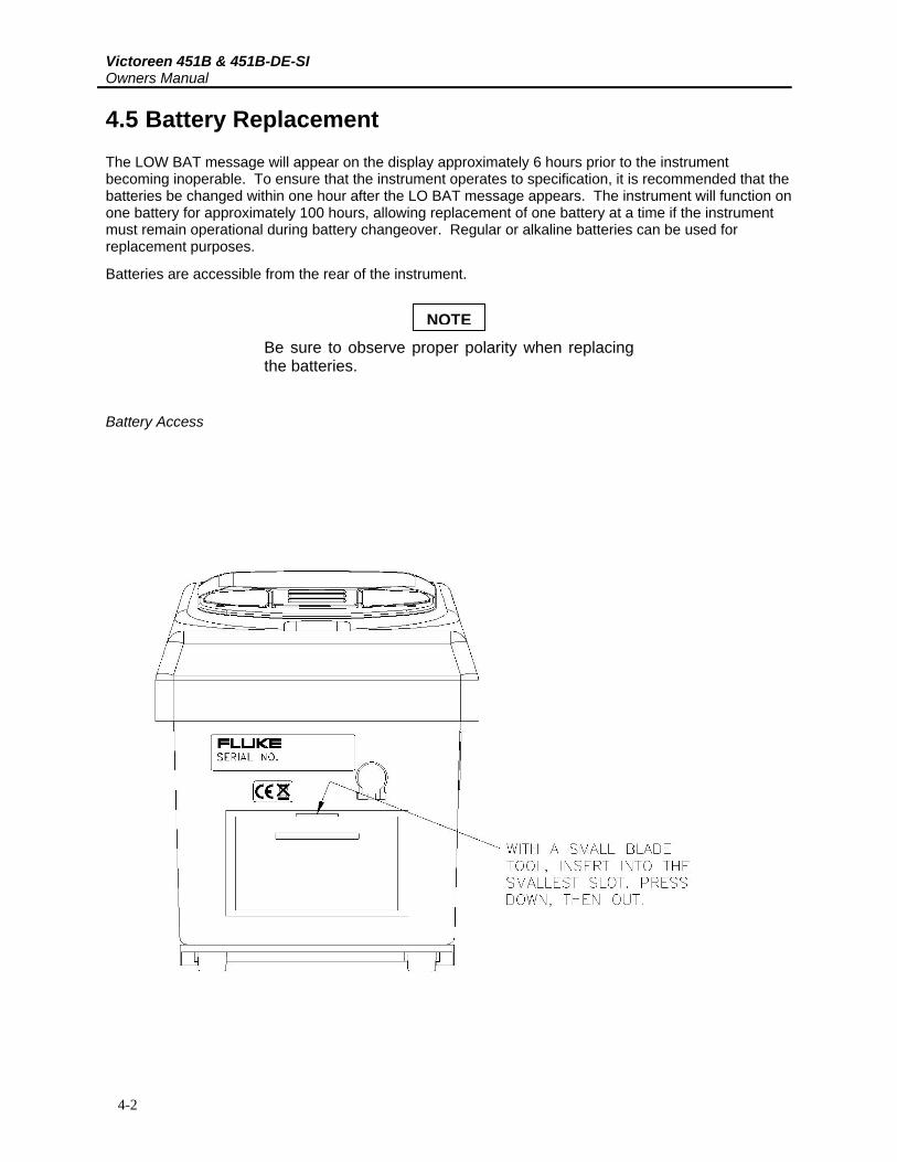
4.5 Battery Replacement The LOW BAT message will appear on the display approximately 6 hours prior to the instrument becoming inoperable. To ensure that the instrument operates to specification, it is recommended that the batteries be changed within one hour after the LO BAT message appears. The instrument will function on one battery for approximately 100 hours, allowing replacement of one battery at a time if the instrument must remain operational during battery changeover. Regular or alkaline batteries can be used for replacement purposes.
Batteries are accessible from the rear of the instrument.
NOTE
Be sure to observe proper polarity when replacing the batteries.
Battery Access

MaintenanceIon Chamber Window Replacement 4
4-3
4.6 Ion Chamber Window Replacement 1. Remove the 9-volt batteries to be sure that the instrument will remain off during the disassembly
process. 2. Remove the 4 screws from the case top. 3. Carefully remove the case bottom from the thick gasket that seals the top and bottom. 4. Remove screws holding phenolic chamber cover to the base. 5. Determine the conductive side of the replacement Mylar sheet using an ohmmeter. 6. Carefully, so as not to crinkle it, place the new Mylar on the top of the chamber, conductive side
facing the chamber. Use adhesive to secure the Mylar to the phenolic chamber. 7. Electrically connect conductive side of Mylar to conductive side of chamber. 8. Any wrinkles in the Mylar may be removed with a hot air gun. Do not apply too much heat; the
Mylar may break. Small ripples in the surface will not affect the operation of the instrument. Attach phenolic chamber to the base.
9. Secure the case top to the case bottom, with the gasket in between, using the four screws removed in step 2.
10. Replace the 9-volt batteries, being sure to observe proper polarity.
4.7 Outer Mylar Window Replacement 1. Remove the 9-volt batteries to be sure that the instrument will remain off during the disassembly
process. 2. Remove the 4 screws from the case top. 3. Carefully remove the case bottom from the thick gasket that seals the top and bottom. 4. Remove the damaged Mylar. Replace with the conductive side facing up, secure with proper
adhesive. 5. Dag conductive side of Mylar to inside of case. 6. Secure the case top to the case bottom, with the gasket in between, using the 4 screws removed in
step 2. 6. Replace the 9-volt batteries, being sure to observe proper polarity.
4.8 Desiccant Regeneration
WARNING
This unit contains lithium cells with a potential voltage of 63 V on the battery assembly. Use care in handling this assembly during removal and installation. Damage to the instrument or bodily harm may result.
Victoreen 451B & 451B-DE-SI Owners Manual
4-4
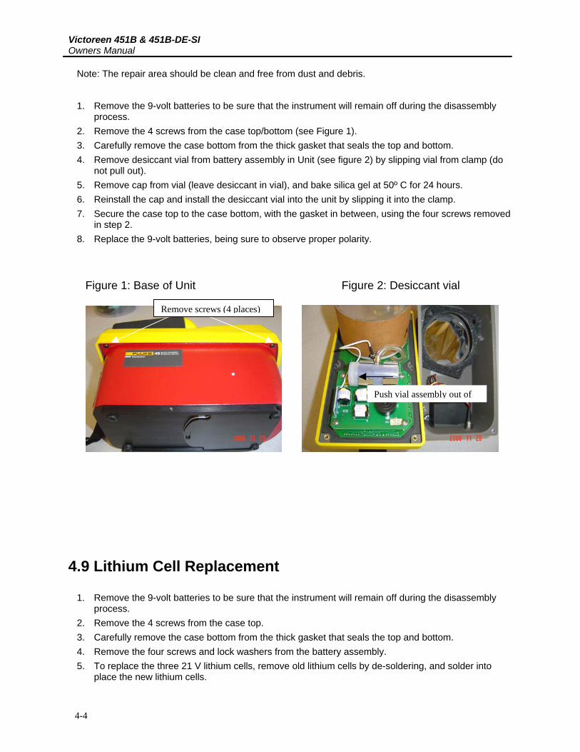
Note: The repair area should be clean and free from dust and debris.
1. Remove the 9-volt batteries to be sure that the instrument will remain off during the disassembly process.
2. Remove the 4 screws from the case top/bottom (see Figure 1). 3. Carefully remove the case bottom from the thick gasket that seals the top and bottom. 4. Remove desiccant vial from battery assembly in Unit (see figure 2) by slipping vial from clamp (do
not pull out). 5. Remove cap from vial (leave desiccant in vial), and bake silica gel at 50º C for 24 hours. 6. Reinstall the cap and install the desiccant vial into the unit by slipping it into the clamp. 7. Secure the case top to the case bottom, with the gasket in between, using the four screws removed
in step 2. 8. Replace the 9-volt batteries, being sure to observe proper polarity.
Figure 1: Base of Unit Figure 2: Desiccant vial
Remove screws (4 places)
Push vial assembly out of
4.9 Lithium Cell Replacement
1. Remove the 9-volt batteries to be sure that the instrument will remain off during the disassembly process.
2. Remove the 4 screws from the case top. 3. Carefully remove the case bottom from the thick gasket that seals the top and bottom. 4. Remove the four screws and lock washers from the battery assembly. 5. To replace the three 21 V lithium cells, remove old lithium cells by de-soldering, and solder into
place the new lithium cells.
MaintenanceIon Chamber Window Replacement 4
4-5
6. Secure the battery board to the survey meter assembly with the 4 screws and lock washers removed in step 4.
7. Secure the case top to the case bottom, with the gasket in between, using the four screws removed in step 2.
8. Replace the 9-volt batteries, being sure to observe proper polarity.
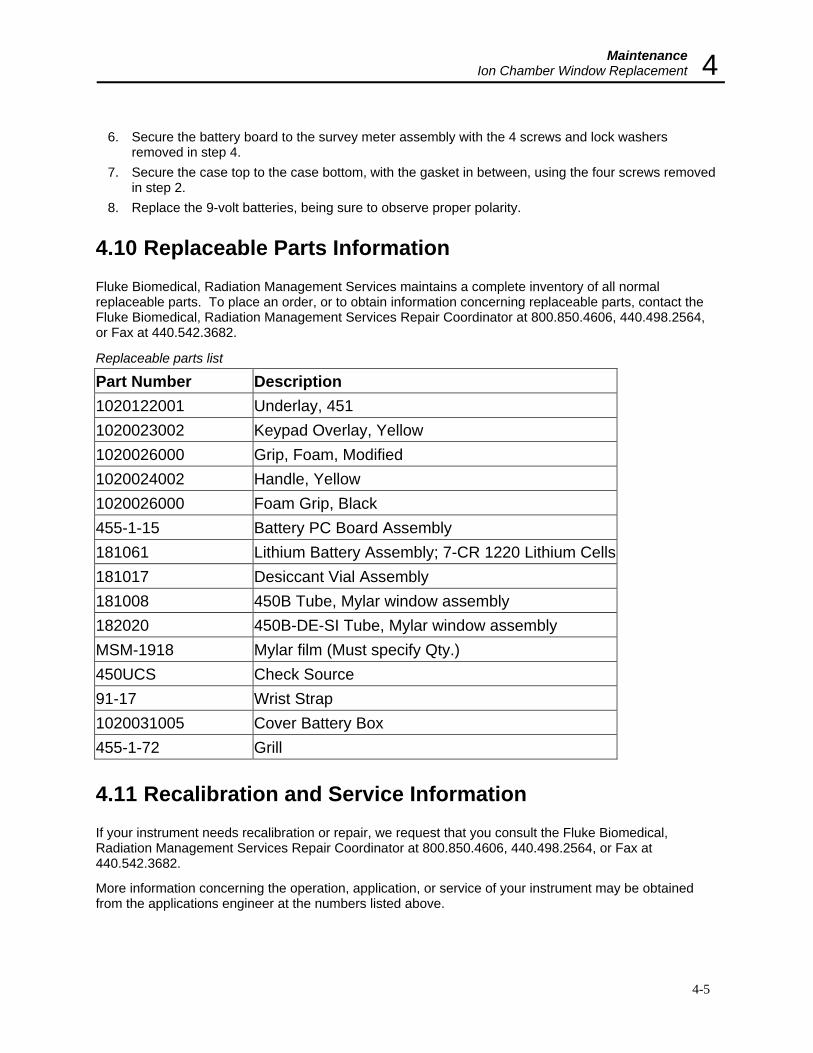
4.10 Replaceable Parts Information Fluke Biomedical, Radiation Management Services maintains a complete inventory of all normal replaceable parts. To place an order, or to obtain information concerning replaceable parts, contact the Fluke Biomedical, Radiation Management Services Repair Coordinator at 800.850.4606, 440.498.2564, or Fax at 440.542.3682.
Replaceable parts list
Part Number Description 1020122001 Underlay, 451 1020023002 Keypad Overlay, Yellow 1020026000 Grip, Foam, Modified 1020024002 Handle, Yellow 1020026000 Foam Grip, Black 455-1-15 Battery PC Board Assembly 181061 Lithium Battery Assembly; 7-CR 1220 Lithium Cells 181017 Desiccant Vial Assembly 181008 450B Tube, Mylar window assembly 182020 450B-DE-SI Tube, Mylar window assembly MSM-1918 Mylar film (Must specify Qty.) 450UCS Check Source 91-17 Wrist Strap 1020031005 Cover Battery Box 455-1-72 Grill
4.11 Recalibration and Service Information If your instrument needs recalibration or repair, we request that you consult the Fluke Biomedical, Radiation Management Services Repair Coordinator at 800.850.4606, 440.498.2564, or Fax at 440.542.3682.
More information concerning the operation, application, or service of your instrument may be obtained from the applications engineer at the numbers listed above.


TroubleshootingTroubleshooting Precautions 5
5-1
Section 5 Troubleshooting
5.1 Troubleshooting Precautions
CAUTION Many components on the printed circuit board are static sensitive. ESD precautions should be observed when handling the printed circuit board assembly.
CAUTION
If the device indicates a relatively high radiation rate, there is a possibility that the unit has been contaminated; CAUTION should be observed when replacing or working on this unit. High rates can quickly cause the operator’s cumulative exposure to increase with the potential for injury.
NOTE
Install fresh batteries prior to performing any calibration on this instrument.
5.2 Troubleshooting
SELF TEST FAILURE If the unit fails self-test, it will remain locked on the firmware revision number. Consult Fluke Biomedical, Radiation Management Services.
HIGH BACKGROUND READINGS Remove desiccant and bake per Section 4.8. After replacement, bake unit at 50° C for 8 hours.
ERRATIC READINGS Check for broken ion chamber window or loose collector. Check for loose chamber bias connector.

Fluke Biomedical 6045 Cochran Road Cleveland, Ohio 44139 440.498.2564 www.flukebiomedical.com