Embed Size (px)
Citation preview
8/6/2019 Vibration Transducer B&K
http://slidepdf.com/reader/full/vibration-transducer-bk 1/38
BA 7675-12, 1
9LEUDWLRQ
7UDQVGXFHUV
DQG
6LJQDO&RQGLWLRQLQJ
l Types of Vibration Transducers
l The Piezoelectric Accelerometer
l Choosing an Accelerometer
l Using an Accelerometer
l Calibration
l Conditioning Amplifiers
$EVWUDFW
A brief explanation of the most commonly used vibration measuringtransducers is given at the beginning of the lecture. This is followed by adescription of various types of piezoelectric accelerometers and their
principle of operation. The basic specifications of accelerometers areexplained and the effect of different mountings and their practical applicationis described in detail. The influence of different environments is discussedand a description of calibration is given. The lecture ends with a descriptionof preamplifiers and signal conditioning.
/(&785(127(
English BA 7675-12
Copyright© 1998Brüel & Kjær Sound and Vibration Measurement A/SAll Rights Reserved
8/6/2019 Vibration Transducer B&K
http://slidepdf.com/reader/full/vibration-transducer-bk 2/38
Page 2
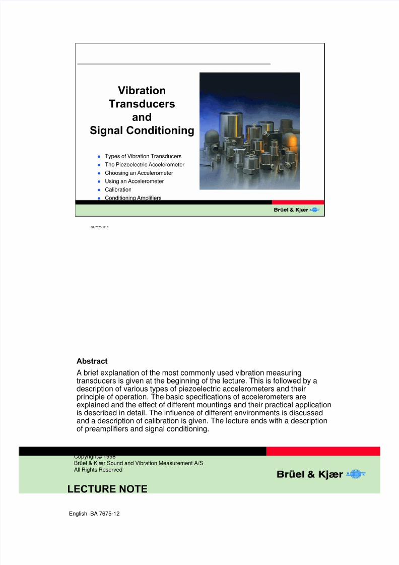
7KH0HDVXUHPHQW&KDLQ
5HPHPEHU The system is never stronger than the weakest link in the chain.
Whenever measurements of physical parameters takes place, the methodused comprises a transducer to convert the parameter into a more practical
parameter, mostly an electromagnetic magnitude because of the vastamount of available methods and components to treat such signals.
Furthermore a certain adaptation between a transducer and normalinstrumentation is often necessary in the form of preamplifiers andconditioning of the signal.
After analysis which today canhave many different forms, the result will bepresented as an output to screen, paper or storage medium.
BA 7675-12, 2
7KH0HDVXUHPHQW&KDLQ
Transducer Preamplifier Detector/
Averager
Filter(s) Output
8/6/2019 Vibration Transducer B&K
http://slidepdf.com/reader/full/vibration-transducer-bk 3/38
Page 3
BA 7675-12, 3
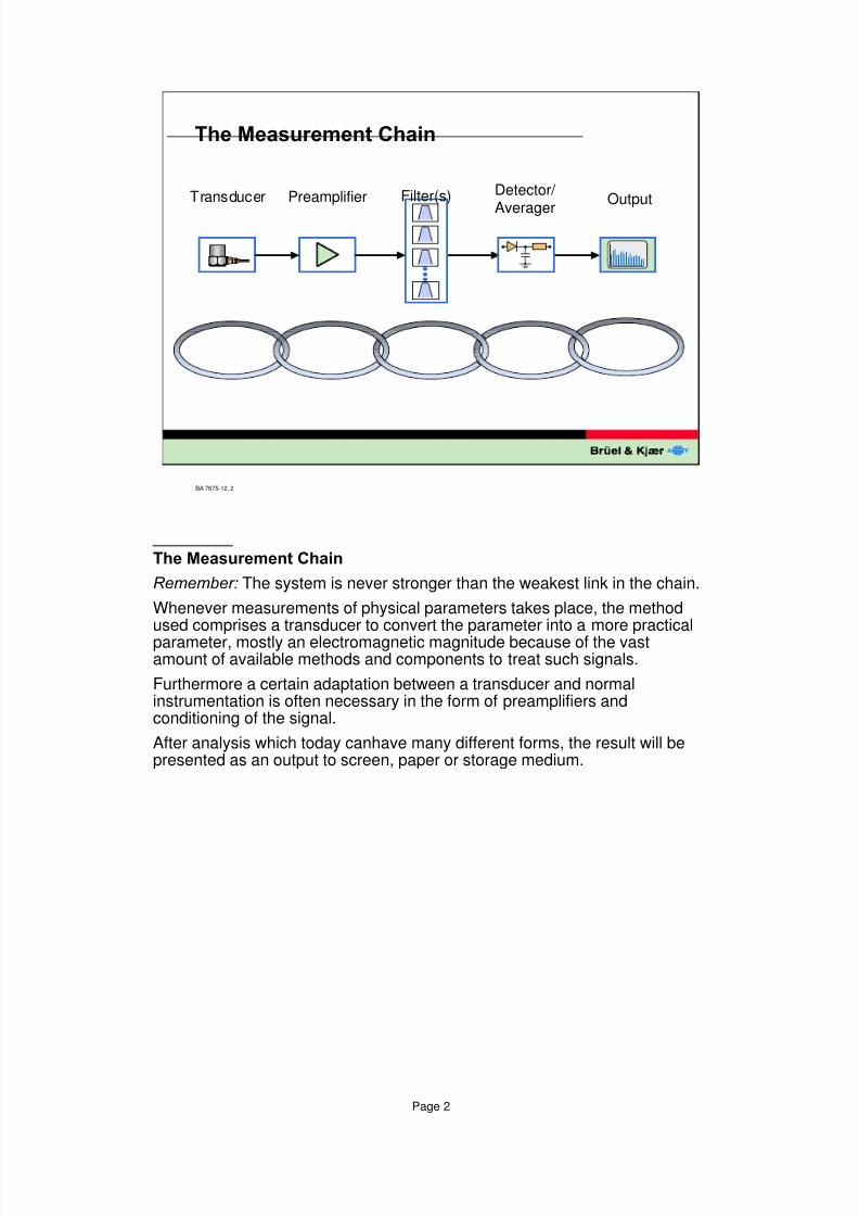
(DUO\0HWKRGVRI9LEUDWLRQ³0HDVXUHPHQWV´
(DUO\0HWKRGVRI9LEUDWLRQ³0HDVXUHPHQW
In the absence of instruments, vibration has been “evaluated” by means oftouching the machine; transfer of the vibration signal from the source to thehead with the aid of a rod, or by using a doctor's stethoscope. In each of
these cases, the signal is evaluated by experience without the aid ofnumerical values to aid comparison.
8/6/2019 Vibration Transducer B&K
http://slidepdf.com/reader/full/vibration-transducer-bk 4/38
Page 4
BA 7675-12, 4
0HFKDQLFDO/HYHU
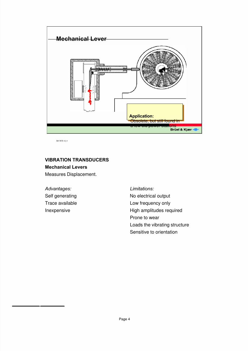
$SSOLFDWLRQ
Obsolete, but still found ina few old power stations
9,%5$7,2175$16'8&(56
0HFKDQLFDO/HYHUV
Measures Displacement.
$GYDQWDJHV /LPLWDWLRQV
Self generating No electrical output
Trace available Low frequency only
Inexpensive High amplitudes required
Prone to wear
Loads the vibrating structure
Sensitive to orientation
8/6/2019 Vibration Transducer B&K
http://slidepdf.com/reader/full/vibration-transducer-bk 5/38
Page 5
BA 7675-12, 5
(GG\&XUUHQW3UR[LPLW\3UREHV
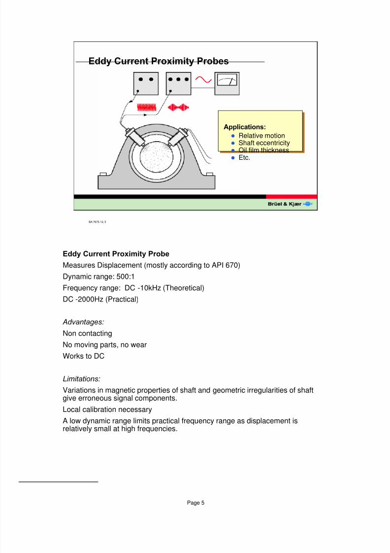
$SSOLFDWLRQV
l Relative motionl Shaft eccentricityl Oil film thicknessl Etc.
(GG\&XUUHQW3UR[LPLW\3UREH
Measures Displacement (mostly according to API 670)
Dynamic range: 500:1
Frequency range: DC -10kHz (Theoretical)DC -2000Hz (Practical)
$GYDQWDJHV
Non contacting
No moving parts, no wear
Works to DC
/LPLWDWLRQV
Variations in magnetic properties of shaft and geometric irregularities of shaftgive erroneous signal components.
Local calibration necessary
A low dynamic range limits practical frequency range as displacement isrelatively small at high frequencies.
8/6/2019 Vibration Transducer B&K
http://slidepdf.com/reader/full/vibration-transducer-bk 6/38
Page 6
BA 7675-12, 6
9HORFLW\3LFNXS
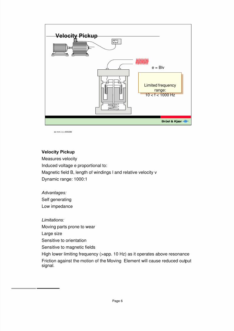
e = Blv
Limited frequencyrange:
10 < f < 1000 Hz
800289
9HORFLW\3LFNXS
Measures velocity
Induced voltage e proportional to:
Magnetic field B, length of windings l and relative velocity vDynamic range: 1000:1
$GYDQWDJHV
Self generating
Low impedance
/LPLWDWLRQV
Moving parts prone to wear
Large size
Sensitive to orientation
Sensitive to magnetic fields
High lower limiting frequency (>app. 10 Hz) as it operates above resonance
Friction against the motion of the Moving Element will cause reduced outputsignal.
8/6/2019 Vibration Transducer B&K
http://slidepdf.com/reader/full/vibration-transducer-bk 7/38
Page 7
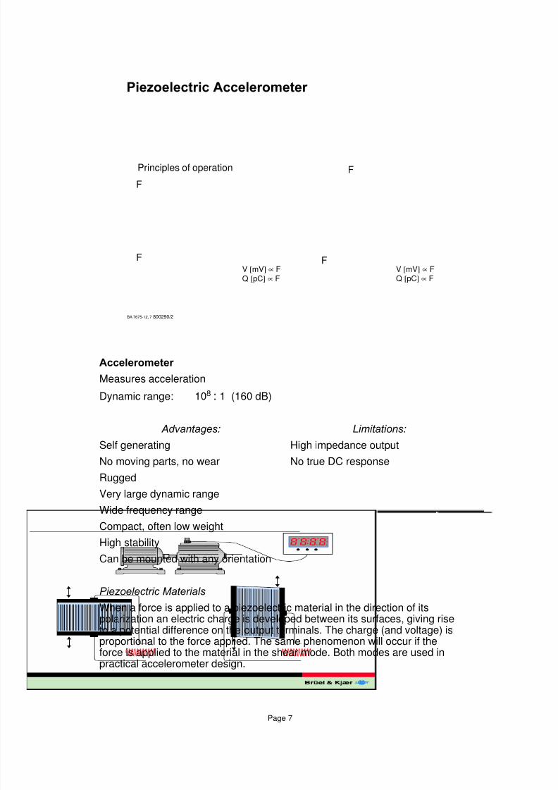
$FFHOHURPHWHU
Measures acceleration
Dynamic range: 108 : 1 (160 dB)
$GYDQWDJHV /LPLWDWLRQV
Self generating High impedance output
No moving parts, no wear No true DC response
Rugged
Very large dynamic range
Wide frequency range
Compact, often low weight
High stability
Can be mounted with any orientation
3LH]RHOHFWULF0DWHULDOV
When a force is applied to a piezoelectric material in the direction of itspolarization an electric charge is developed between its surfaces, giving riseto a potential difference on the output terminals. The charge (and voltage) isproportional to the force applied. The same phenomenon will occur if theforce is applied to the material in the shear mode. Both modes are used inpractical accelerometer design.
BA 7675-12, 7
3LH]RHOHFWULF$FFHOHURPHWHU
Principles of operation
F
F F
F
800290/2
V [mV] ∝ F
Q [pC] ∝ F
V [mV] ∝ F
Q [pC] ∝ F
8/6/2019 Vibration Transducer B&K
http://slidepdf.com/reader/full/vibration-transducer-bk 8/38
Page 8
BA 7675-12, 8
7\SHVRI$FFHOHURPHWHUV
3 3LH]RHOHFWULF(OHPHQWV ( %XLOWLQ(OHFWURQLFV 6 6SULQJ
5&ODPSLQJ5LQJ % %DVH06HLVPLF0DVV
800284
P
M
RB
3ODQDU6KHDU
EMP
B
$QQXODU6KHDU
S
B
P
M
&HQWUHPRXQWHG&RPSUHVVLRQ
P
RM
B
'HOWD6KHDU �
P
B
RM
E
2UWKR6KHDU �
PB
MR
7KHWD6KHDU �
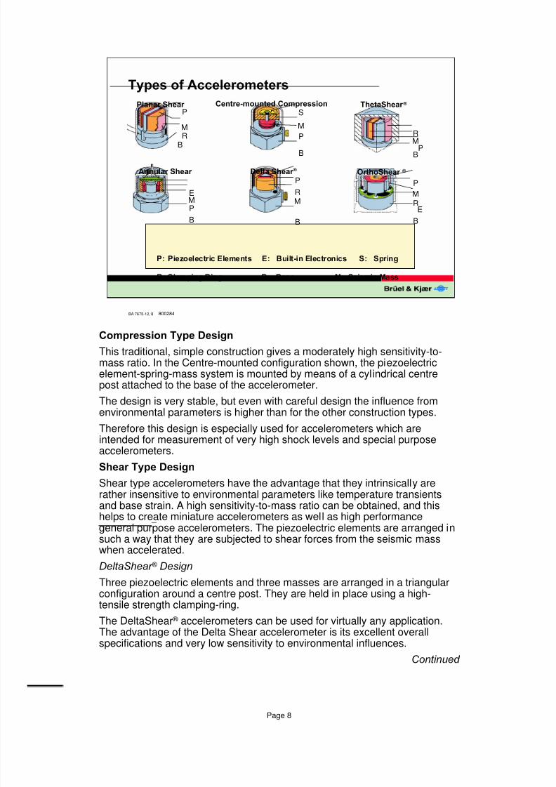
&RPSUHVVLRQ7\SH'HVLJQ
This traditional, simple construction gives a moderately high sensitivity-to-mass ratio. In the Centre-mounted configuration shown, the piezoelectricelement-spring-mass system is mounted by means of a cylindrical centrepost attached to the base of the accelerometer.
The design is very stable, but even with careful design the influence from
environmental parameters is higher than for the other construction types.Therefore this design is especially used for accelerometers which areintended for measurement of very high shock levels and special purposeaccelerometers.
6KHDU7\SH'HVLJQ
Shear type accelerometers have the advantage that they intrinsically arerather insensitive to environmental parameters like temperature transientsand base strain. A high sensitivity-to-mass ratio can be obtained, and thishelps to create miniature accelerometers as well as high performancegeneral purpose accelerometers. The piezoelectric elements are arranged insuch a way that they are subjected to shear forces from the seismic mass
when accelerated.'HOWD6KHDU � 'HVLJQ
Three piezoelectric elements and three masses are arranged in a triangularconfiguration around a centre post. They are held in place using a high-tensile strength clamping-ring.
The DeltaShear ® accelerometers can be used for virtually any application.The advantage of the Delta Shear accelerometer is its excellent overallspecifications and very low sensitivity to environmental influences.
&RQWLQXHG
8/6/2019 Vibration Transducer B&K
http://slidepdf.com/reader/full/vibration-transducer-bk 9/38
Page 9
BA 7675-12, 9
20
2SHUDWLRQDO5DQJHRI9LEUDWLRQ7UDQVGXFHUV
1
PiezoelectricAccelerometer
Velocitytransducer
Eddy currentProximity probe
0.2 2 200 2k 20kHz Frequency
RelativeAmplitude
108:1
106:1
10 000:1
100:1
930656
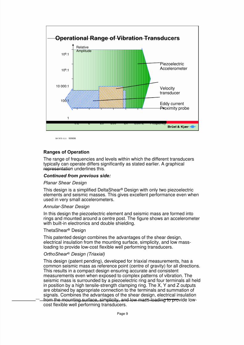
5DQJHVRI2SHUDWLRQ
The range of frequencies and levels within which the different transducerstypically can operate differs significantly as stated earlier. A graphicalrepresentation underlines this.
&RQWLQXHGIURPSUHYLRXVVLGH
3ODQDU6KHDU 'HVLJQ
This design is a simplified DeltaShear ® Design with only two piezoelectricelements and seismic masses. This gives excellent performance even whenused in very small accelerometers.
$QQXODU6KHDU 'HVLJQ
In this design the piezoelectric element and seismic mass are formed intorings and mounted around a centre post. The figure shows an accelerometerwith built-in electronics and double shielding.
ThetaShear ® Design
This patented design combines the advantages of the shear design,
electrical insulation from the mounting surface, simplicity, and low mass-loading to provide low-cost flexible well performing transducers.
2UWKR6KHDU �'HVLJQ7ULD[LDO
This design (patent pending), developed for triaxial measurements, has acommon seismic mass as reference point (centre of gravity) for all directions.This results in a compact design ensuring accurate and consistentmeasurements even when exposed to complex patterns of vibration. Theseismic mass is surrounded by a piezoelectric ring and four terminals all heldin position by a high tensile-strength clamping ring. The X, Y and Z outputsare obtained by appropriate connection to the terminals and summation ofsignals. Combines the advantages of the shear design, electrical insulation
from the mounting surface, simplicity, and low mass-loading to provide low-cost flexible well performing transducers.
8/6/2019 Vibration Transducer B&K
http://slidepdf.com/reader/full/vibration-transducer-bk 10/38
Page 10
BA 7675-12, 10
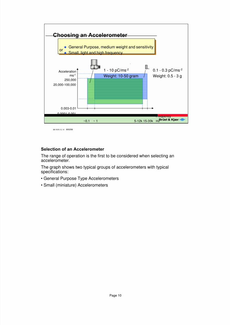
&KRRVLQJDQ$FFHOHURPHWHU
l General Purpose, medium weight and sensitivity
l Small, light and high frequencyor
0.1 - 0.3 pC/ms-2
Weight: 0.5 - 3 g
1 - 10 pC/ms-2
Weight: 10-50 gramAcceleration
Frequency
ms-2
250,000
20,000-100,000
0.003-0.01
0.0001-0.001
~0.1 ~ 1 5-12k 15-30k Hz
800299
6HOHFWLRQRIDQ$FFHOHURPHWHU
The range of operation is the first to be considered when selecting anaccelerometer.
The graph shows two typical groups of accelerometers with typical
specifications:
• General Purpose Type Accelerometers
• Small (miniature) Accelerometers
8/6/2019 Vibration Transducer B&K
http://slidepdf.com/reader/full/vibration-transducer-bk 11/38
Page 11
BA 7675-12, 11
8VHIXO)UHTXHQF\5DQJH
Input
Output
Acc.ms-2
(pC)
~ 35 dB
~ 10%
0.3 f0
f1 f0 Frequency
800298
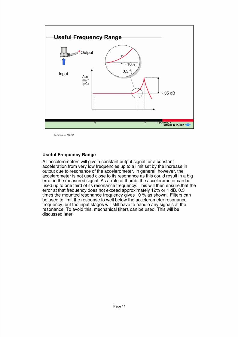
8VHIXO)UHTXHQF\5DQJH
All accelerometers will give a constant output signal for a constantacceleration from very low frequencies up to a limit set by the increase inoutput due to resonance of the accelerometer. In general, however, the
accelerometer is not used close to its resonance as this could result in a bigerror in the measured signal. As a rule of thumb, the accelerometer can beused up to one third of its resonance frequency. This will then ensure that theerror at that frequency does not exceed approximately 12% or 1 dB. 0.3times the mounted resonance frequency gives 10 % as shown. Filters canbe used to limit the response to well below the accelerometer resonancefrequency, but the input stages will still have to handle any signals at theresonance. To avoid this, mechanical filters can be used. This will bediscussed later.
8/6/2019 Vibration Transducer B&K
http://slidepdf.com/reader/full/vibration-transducer-bk 12/38
Page 12
BA 7675-12, 12
6HQVLWLYLW\DQG)UHTXHQF\5DQJH
SensitivitypC/ms-2
31.6
1
0.004
13 42 180 kHz
800295
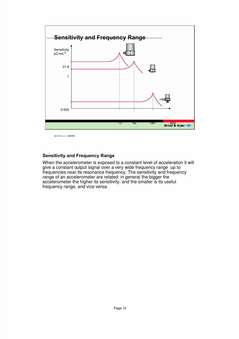
6HQVLWLYLW\DQG)UHTXHQF\5DQJH
When the accelerometer is exposed to a constant level of acceleration it willgive a constant output signal over a very wide frequency range up tofrequencies near its resonance frequency. The sensitivity and frequency
range of an accelerometer are related: in general the bigger theaccelerometer the higher its sensitivity, and the smaller is its usefulfrequency range, and vice versa.
8/6/2019 Vibration Transducer B&K
http://slidepdf.com/reader/full/vibration-transducer-bk 13/38
Page 13
BA 7675-12, 13
%HHVZD[LeveldB
Max.40 °C
200 500 1k 2k 5k 10k 20k 30k 50 kHz
$FFHOHURPHWHU0RXQWLQJ²)L[HG
7KLQGRXEOH
DGKHVLYHWDSH
&HPHQWLQJVWXG
6WXG0RXQWLQJ
930616
30
20
10
0
Frequency
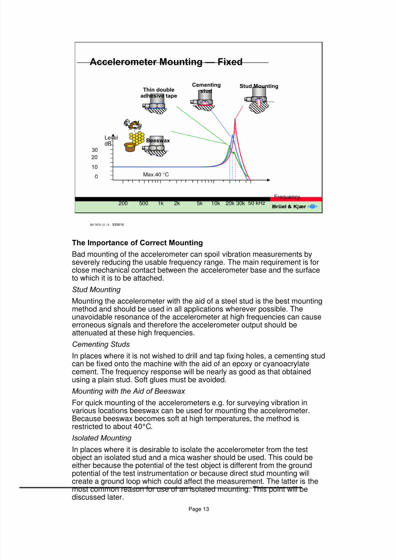
7KH,PSRUWDQFHRI&RUUHFW0RXQWLQJ
Bad mounting of the accelerometer can spoil vibration measurements byseverely reducing the usable frequency range. The main requirement is forclose mechanical contact between the accelerometer base and the surfaceto which it is to be attached.
6WXG0RXQWLQJ
Mounting the accelerometer with the aid of a steel stud is the best mountingmethod and should be used in all applications wherever possible. Theunavoidable resonance of the accelerometer at high frequencies can causeerroneous signals and therefore the accelerometer output should beattenuated at these high frequencies.
&HPHQWLQJ6WXGV
In places where it is not wished to drill and tap fixing holes, a cementing studcan be fixed onto the machine with the aid of an epoxy or cyanoacrylatecement. The frequency response will be nearly as good as that obtainedusing a plain stud. Soft glues must be avoided.
0RXQWLQJZLWKWKH$LGRI%HHVZD[ For quick mounting of the accelerometers e.g. for surveying vibration invarious locations beeswax can be used for mounting the accelerometer.Because beeswax becomes soft at high temperatures, the method isrestricted to about 40°C.
,VRODWHG0RXQWLQJ
In places where it is desirable to isolate the accelerometer from the testobject an isolated stud and a mica washer should be used. This could beeither because the potential of the test object is different from the groundpotential of the test instrumentation or because direct stud mounting willcreate a ground loop which could affect the measurement. The latter is the
most common reason for use of an isolated mounting. This point will bediscussed later.
8/6/2019 Vibration Transducer B&K
http://slidepdf.com/reader/full/vibration-transducer-bk 14/38
Page 14
BA 7675-12, 14
$FFHOHURPHWHU0RXQWLQJ²+DQGKHOG
+DQGKHOGSUREH 0DJQHW
, Q Y H U W H G
3 U R E H
930617
30
20
10
0
200 500 1k 2k 5k 10k 20k 30k 50kHzFrequency
LeveldB
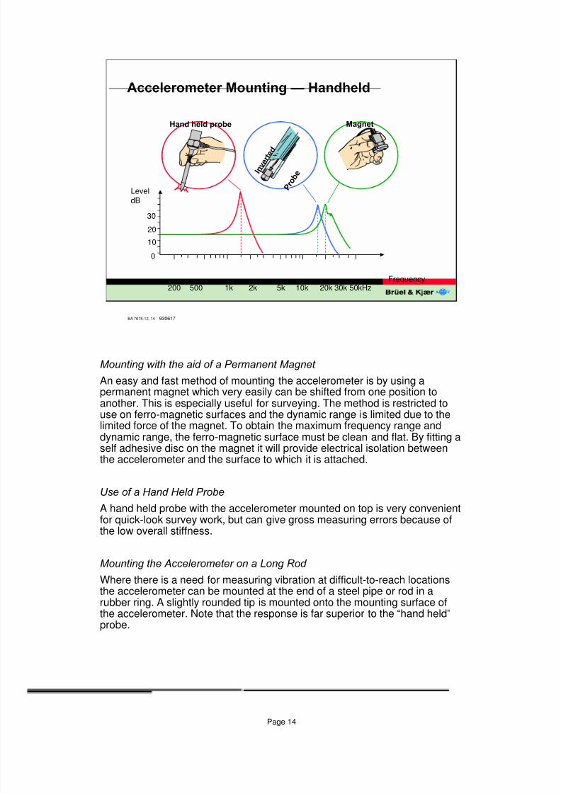
0RXQWLQJZLWKWKHDLGRID3HUPDQHQW0DJQHW
An easy and fast method of mounting the accelerometer is by using apermanent magnet which very easily can be shifted from one position toanother. This is especially useful for surveying. The method is restricted to
use on ferro-magnetic surfaces and the dynamic range is limited due to thelimited force of the magnet. To obtain the maximum frequency range anddynamic range, the ferro-magnetic surface must be clean and flat. By fitting aself adhesive disc on the magnet it will provide electrical isolation betweenthe accelerometer and the surface to which it is attached.
8VHRID+DQG+HOG3UREH
A hand held probe with the accelerometer mounted on top is very convenientfor quick-look survey work, but can give gross measuring errors because ofthe low overall stiffness.
0RXQWLQJWKH$FFHOHURPHWHURQD/RQJ5RG
Where there is a need for measuring vibration at difficult-to-reach locationsthe accelerometer can be mounted at the end of a steel pipe or rod in arubber ring. A slightly rounded tip is mounted onto the mounting surface ofthe accelerometer. Note that the response is far superior to the “hand held”probe.
8/6/2019 Vibration Transducer B&K
http://slidepdf.com/reader/full/vibration-transducer-bk 15/38
Page 15
BA 7675-12, 15
,VRODWLQJWKH$FFHOHURPHWHU
(OHFWULFDO
(Prevention of ground loops)
Micawasher
Insulatingstud
dB
0HFKDQLFDO)LOWHU
(Protection against high shocks)
Frequency
2kFrequency
1k
930618
0
10
20
5k 10k 20k 30k 50kHz
2k 5k 10k 20k 30k 50kHz
10
0
-10
1k
dB
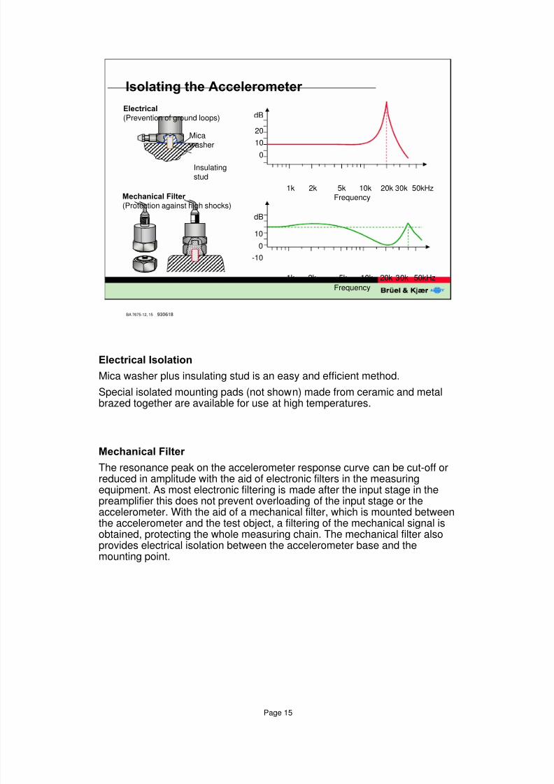
(OHFWULFDO,VRODWLRQ
Mica washer plus insulating stud is an easy and efficient method.
Special isolated mounting pads (not shown) made from ceramic and metalbrazed together are available for use at high temperatures.
0HFKDQLFDO)LOWHU
The resonance peak on the accelerometer response curve can be cut-off orreduced in amplitude with the aid of electronic filters in the measuringequipment. As most electronic filtering is made after the input stage in thepreamplifier this does not prevent overloading of the input stage or theaccelerometer. With the aid of a mechanical filter, which is mounted betweenthe accelerometer and the test object, a filtering of the mechanical signal isobtained, protecting the whole measuring chain. The mechanical filter also
provides electrical isolation between the accelerometer base and themounting point.
8/6/2019 Vibration Transducer B&K
http://slidepdf.com/reader/full/vibration-transducer-bk 16/38
Page 16
BA 7675-12, 16
&KRRVLQJD0RXQWLQJ3RVLWLRQ
B
A
C
D
800305
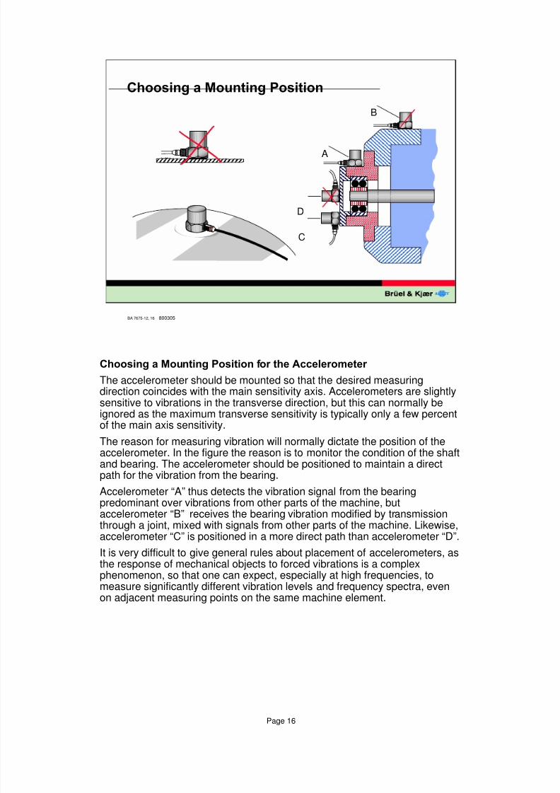
&KRRVLQJD0RXQWLQJ3RVLWLRQIRUWKH$FFHOHURPHWHU
The accelerometer should be mounted so that the desired measuringdirection coincides with the main sensitivity axis. Accelerometers are slightlysensitive to vibrations in the transverse direction, but this can normally be
ignored as the maximum transverse sensitivity is typically only a few percentof the main axis sensitivity.
The reason for measuring vibration will normally dictate the position of theaccelerometer. In the figure the reason is to monitor the condition of the shaftand bearing. The accelerometer should be positioned to maintain a directpath for the vibration from the bearing.
Accelerometer “A” thus detects the vibration signal from the bearingpredominant over vibrations from other parts of the machine, butaccelerometer “B” receives the bearing vibration modified by transmissionthrough a joint, mixed with signals from other parts of the machine. Likewise,accelerometer “C” is positioned in a more direct path than accelerometer “D”.
It is very difficult to give general rules about placement of accelerometers, asthe response of mechanical objects to forced vibrations is a complexphenomenon, so that one can expect, especially at high frequencies, tomeasure significantly different vibration levels and frequency spectra, evenon adjacent measuring points on the same machine element.
8/6/2019 Vibration Transducer B&K
http://slidepdf.com/reader/full/vibration-transducer-bk 17/38
Page 17
BA 7675-12, 17
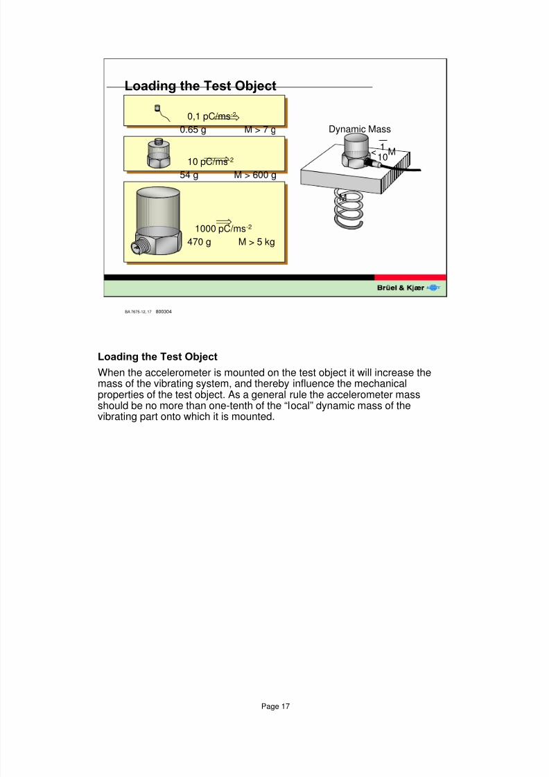
/RDGLQJWKH7HVW2EMHFW
0,1 pC/ms-2
0.65 g M > 7 g
10 pC/ms-2
54 g M > 600 g
1000 pC/ms-2
470 g M > 5 kg
M
<1
10M
Dynamic Mass
800304
/RDGLQJWKH7HVW2EMHFW
When the accelerometer is mounted on the test object it will increase themass of the vibrating system, and thereby influence the mechanicalproperties of the test object. As a general rule the accelerometer mass
should be no more than one-tenth of the “local” dynamic mass of thevibrating part onto which it is mounted.
8/6/2019 Vibration Transducer B&K
http://slidepdf.com/reader/full/vibration-transducer-bk 18/38
Page 18
BA 7675-12, 18
7UDQVYHUVH6HQVLWLYLW\
Accelerometer
mountingaxis
Red dot
Axis ofmaximumsensitivity
�
A x i s o f m i n i m u m
T r a n s v e r s e
s e n s i t i v i t y $ [ L V
R I P D
[ L P X P
W U D Q V Y H
U V H V H
Q V L W L Y
L W \
Max. transversesensitivity < 4 %
100 %
< 4 %
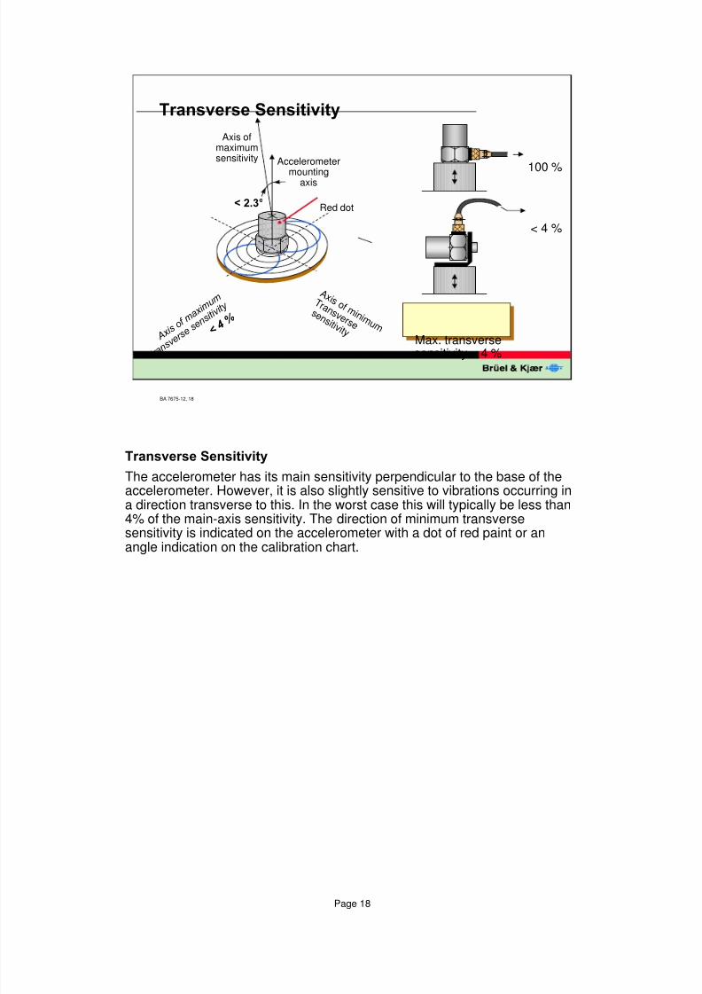
7UDQVYHUVH6HQVLWLYLW\
The accelerometer has its main sensitivity perpendicular to the base of theaccelerometer. However, it is also slightly sensitive to vibrations occurring ina direction transverse to this. In the worst case this will typically be less than
4% of the main-axis sensitivity. The direction of minimum transversesensitivity is indicated on the accelerometer with a dot of red paint or anangle indication on the calibration chart.
8/6/2019 Vibration Transducer B&K
http://slidepdf.com/reader/full/vibration-transducer-bk 19/38
Page 19
BA 7675-12, 19
7ULERHOHFWULF1RLVH
800317
+ ++
+ +
+
+++
+
+
+
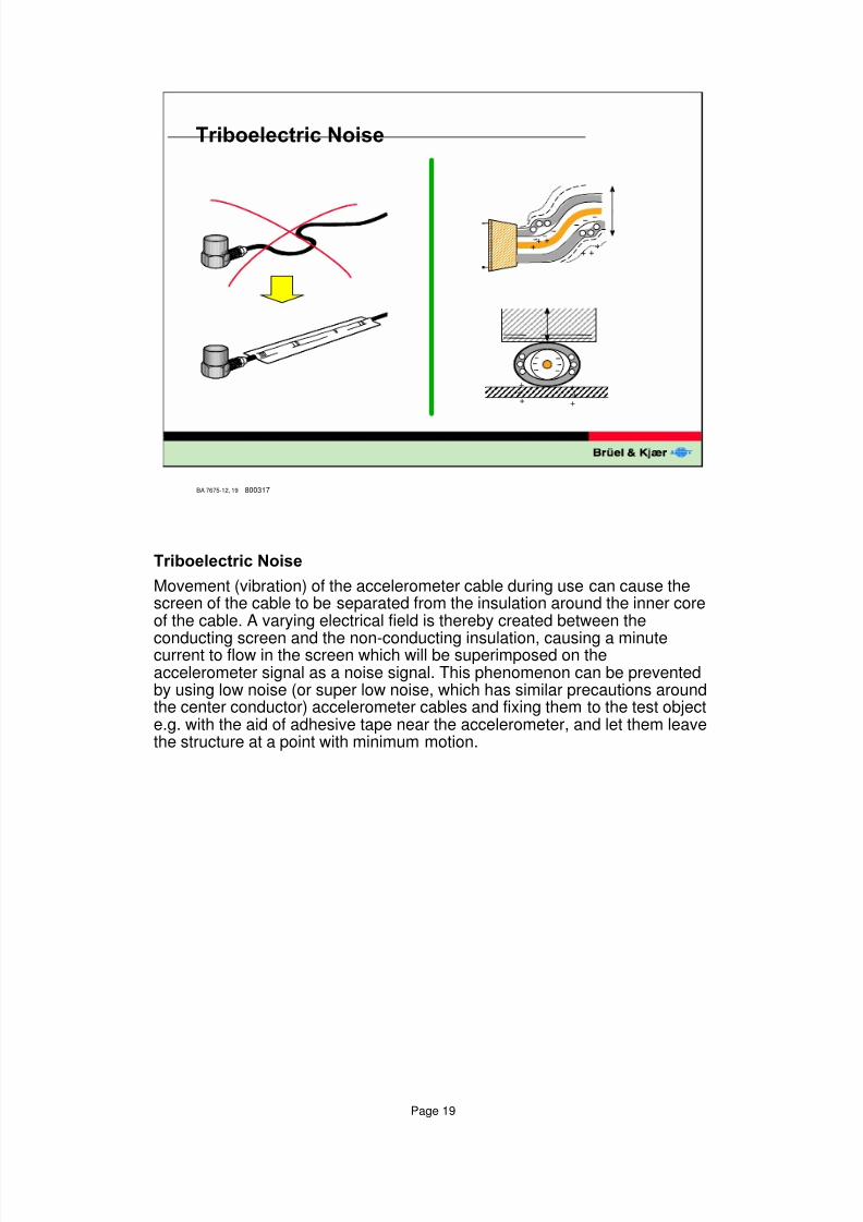
7ULERHOHFWULF1RLVH
Movement (vibration) of the accelerometer cable during use can cause thescreen of the cable to be separated from the insulation around the inner coreof the cable. A varying electrical field is thereby created between the
conducting screen and the non-conducting insulation, causing a minutecurrent to flow in the screen which will be superimposed on theaccelerometer signal as a noise signal. This phenomenon can be preventedby using low noise (or super low noise, which has similar precautions aroundthe center conductor) accelerometer cables and fixing them to the test objecte.g. with the aid of adhesive tape near the accelerometer, and let them leavethe structure at a point with minimum motion.
8/6/2019 Vibration Transducer B&K
http://slidepdf.com/reader/full/vibration-transducer-bk 20/38
Page 20
BA 7675-12, 20
(QYLURQPHQWDO(IIHFWV
l Base Strain
l Humidity
l Acoustic noise
l Corrosive substances
l Magnetic fields
l Nuclear radiation
800314
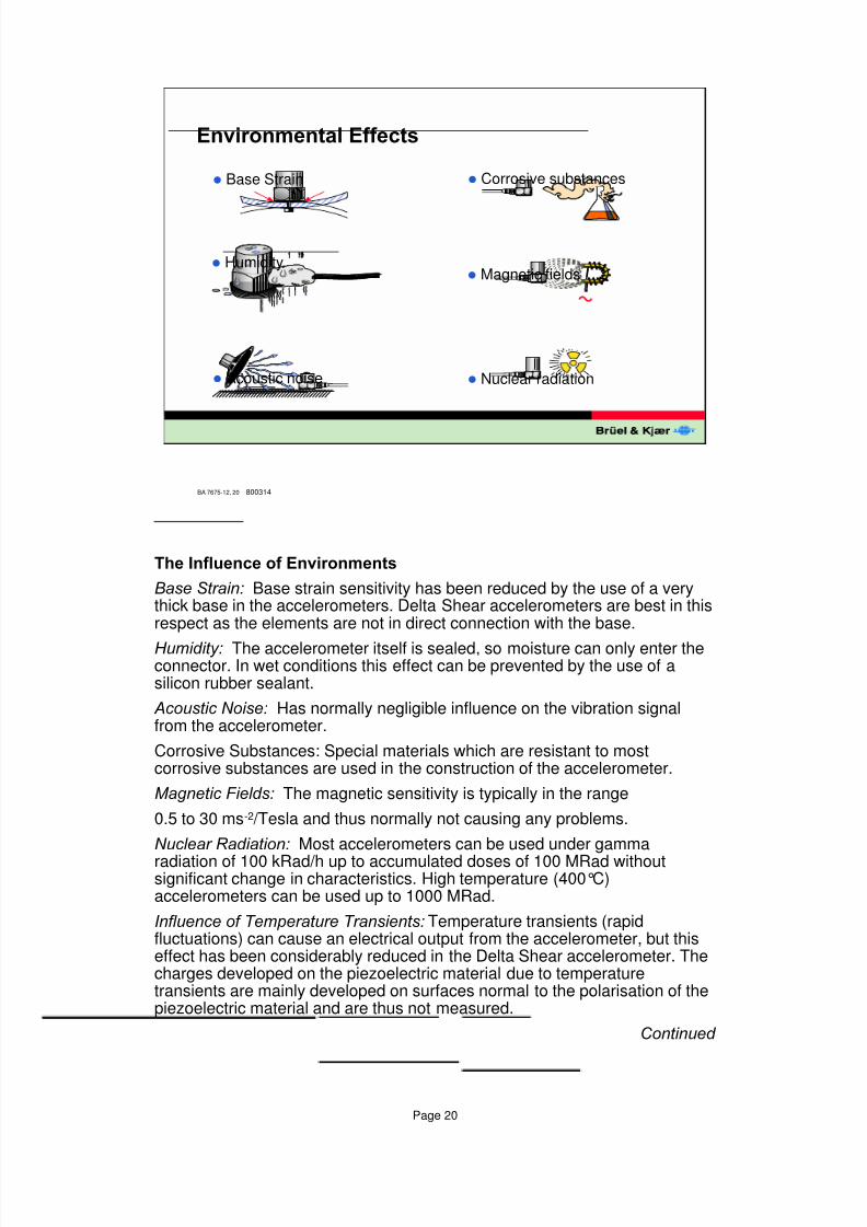
7KH,QIOXHQFHRI(QYLURQPHQWV
%DVH6WUDLQ Base strain sensitivity has been reduced by the use of a verythick base in the accelerometers. Delta Shear accelerometers are best in thisrespect as the elements are not in direct connection with the base.
+XPLGLW\ The accelerometer itself is sealed, so moisture can only enter theconnector. In wet conditions this effect can be prevented by the use of asilicon rubber sealant.
$FRXVWLF1RLVH Has normally negligible influence on the vibration signalfrom the accelerometer.
Corrosive Substances: Special materials which are resistant to mostcorrosive substances are used in the construction of the accelerometer.
0DJQHWLF)LHOGV The magnetic sensitivity is typically in the range
0.5 to 30 ms-2 /Tesla and thus normally not causing any problems.
1XFOHDU5DGLDWLRQ Most accelerometers can be used under gamma
radiation of 100 kRad/h up to accumulated doses of 100 MRad withoutsignificant change in characteristics. High temperature (400°C)accelerometers can be used up to 1000 MRad.
,QIOXHQFHRI7HPSHUDWXUH7UDQVLHQWVTemperature transients (rapidfluctuations) can cause an electrical output from the accelerometer, but thiseffect has been considerably reduced in the Delta Shear accelerometer. Thecharges developed on the piezoelectric material due to temperaturetransients are mainly developed on surfaces normal to the polarisation of thepiezoelectric material and are thus not measured.
&RQWLQXHG
8/6/2019 Vibration Transducer B&K
http://slidepdf.com/reader/full/vibration-transducer-bk 21/38
Page 21
BA 7675-12, 21
6SHFLDO$FFHOHURPHWHUV
Calibration
High temperature Shock
Triaxialz
yx
High sensitivity(with built-in amplifier)
55 g 10 g
Tmax.= 400° C amax.= 1000 km-2amin.= 20 × 10-6 ms-2
316 mV/ms-2
&RQWLQXHGIURPSUHYLRXVVOLGH
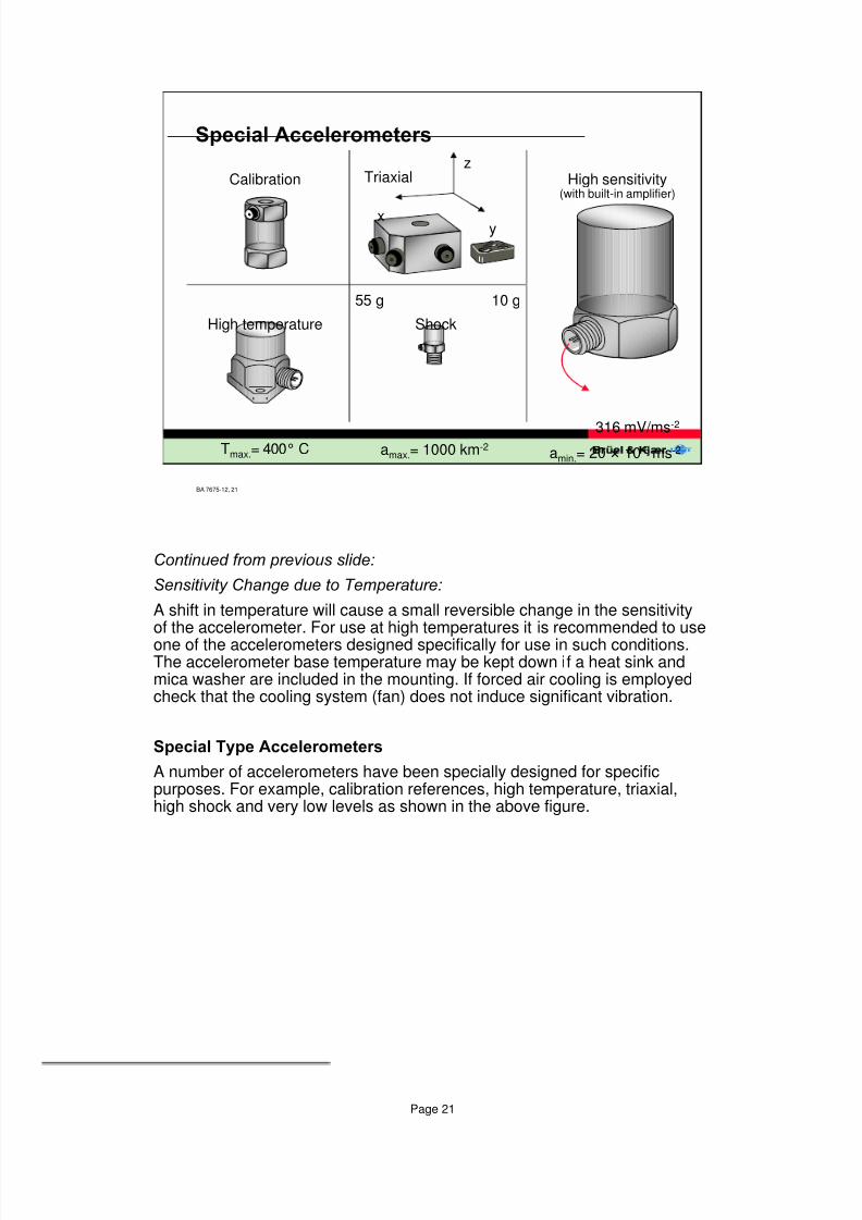
6HQVLWLYLW\&KDQJHGXHWR7HPSHUDWXUH
A shift in temperature will cause a small reversible change in the sensitivityof the accelerometer. For use at high temperatures it is recommended to use
one of the accelerometers designed specifically for use in such conditions.The accelerometer base temperature may be kept down if a heat sink andmica washer are included in the mounting. If forced air cooling is employedcheck that the cooling system (fan) does not induce significant vibration.
6SHFLDO7\SH$FFHOHURPHWHUV
A number of accelerometers have been specially designed for specificpurposes. For example, calibration references, high temperature, triaxial,high shock and very low levels as shown in the above figure.
8/6/2019 Vibration Transducer B&K
http://slidepdf.com/reader/full/vibration-transducer-bk 22/38
Page 22
BA 7675-12, 22
+DQGOHWKH$FFHOHURPHWHU&DUHIXOO\
930616
2 5 100 2 5 1k 2 5 10k 20 50
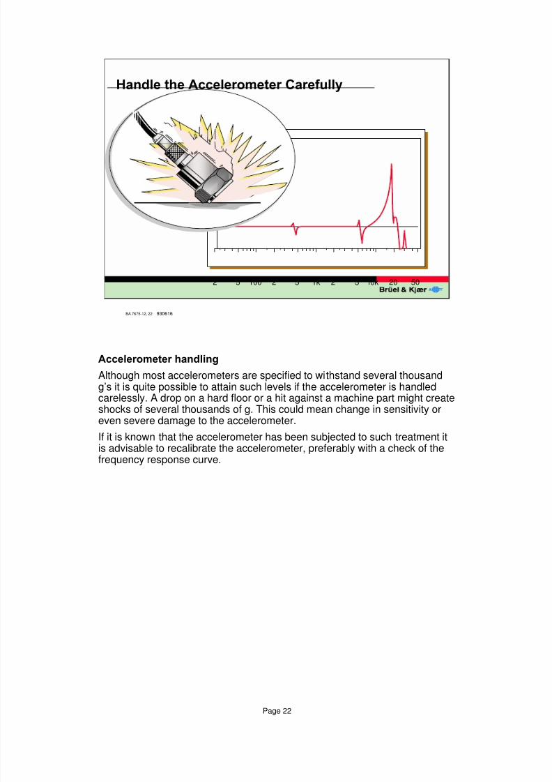
$FFHOHURPHWHUKDQGOLQJ
Although most accelerometers are specified to withstand several thousandg’s it is quite possible to attain such levels if the accelerometer is handledcarelessly. A drop on a hard floor or a hit against a machine part might create
shocks of several thousands of g. This could mean change in sensitivity oreven severe damage to the accelerometer.
If it is known that the accelerometer has been subjected to such treatment itis advisable to recalibrate the accelerometer, preferably with a check of thefrequency response curve.
8/6/2019 Vibration Transducer B&K
http://slidepdf.com/reader/full/vibration-transducer-bk 23/38
Page 23
BA 7675-12, 23
7KH&DOLEUDWLRQ&KDUW
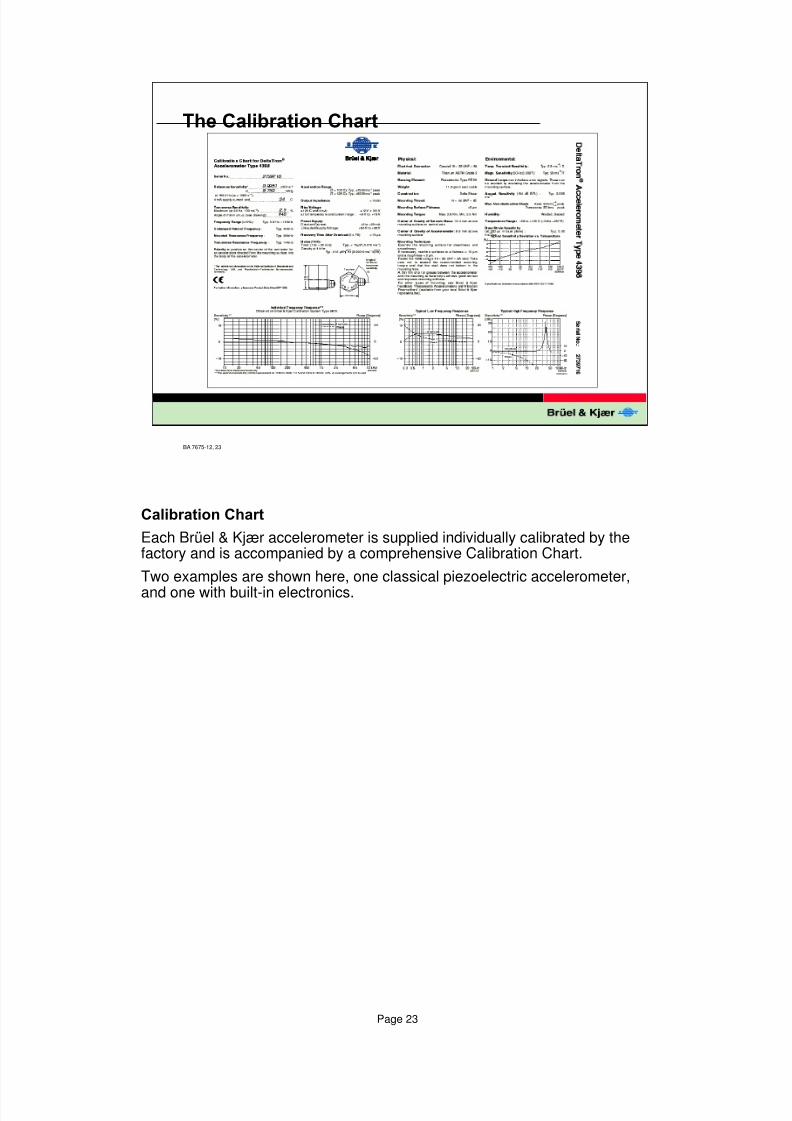
&DOLEUDWLRQ&KDUW
Each Brüel & Kjær accelerometer is supplied individually calibrated by thefactory and is accompanied by a comprehensive Calibration Chart.
Two examples are shown here, one classical piezoelectric accelerometer,
and one with built-in electronics.
8/6/2019 Vibration Transducer B&K
http://slidepdf.com/reader/full/vibration-transducer-bk 24/38
Page 24
BA 7675-12, 24
7KH&DOLEUDWLRQ&KDUW
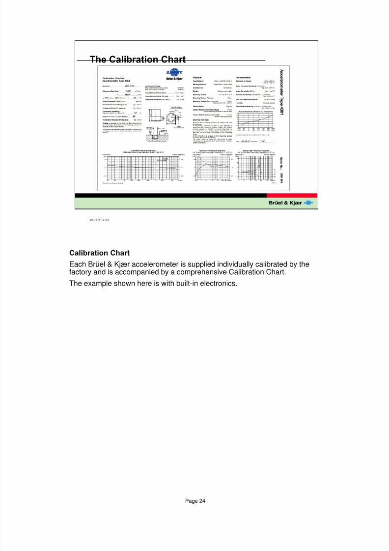
&DOLEUDWLRQ&KDUW
Each Brüel & Kjær accelerometer is supplied individually calibrated by thefactory and is accompanied by a comprehensive Calibration Chart.
The example shown here is with built-in electronics.
8/6/2019 Vibration Transducer B&K
http://slidepdf.com/reader/full/vibration-transducer-bk 25/38
Page 25
BA 7675-12, 25
)RUFH7UDQVGXFHU
F1
F2
a
ForceTransducer
930624
Piezoelectricmaterial
Force
Transducer
)RUFH7UDQVGXFHUV
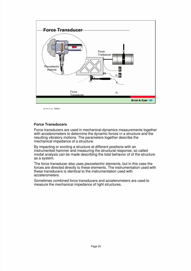
Force transducers are used in mechanical-dynamics measurements togetherwith accelerometers to determine the dynamic forces in a structure and theresulting vibratory motions. The parameters together describe the
mechanical impedance of a structure.By impacting or exciting a structure at different positions with aninstrumented hammer and measuring the structural response, so calledmodal analysis can be made describing the total behavior of of the structureas a system.
The force transducer also uses piezoelectric elements, but in this case theforces are directed directly to these elements. The instrumentation used withthese transducers is identical to the instrumentation used withaccelerometers.
Sometimes combined force transducers and accelerometers are used tomeasure the mechanical impedance of light structures.
8/6/2019 Vibration Transducer B&K
http://slidepdf.com/reader/full/vibration-transducer-bk 26/38
Page 26
BA 7675-12, 26
&DOLEUDWLRQ
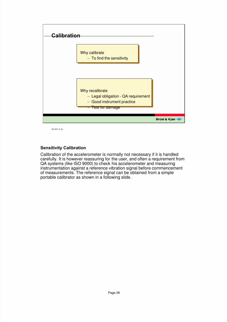
Why calibrate
– To find the sensitivity
Why recalibrate
– Legal obligation - QA requirement
– Good instrument practice
– Test for damage
6HQVLWLYLW\&DOLEUDWLRQ
Calibration of the accelerometer is normally not necessary if it is handledcarefully. It is however reassuring for the user, and often a requirement fromQA systems (like ISO 9000) to check his accelerometer and measuring
instrumentation against a reference vibration signal before commencementof measurements. The reference signal can be obtained from a simpleportable calibrator as shown in a following slide.
8/6/2019 Vibration Transducer B&K
http://slidepdf.com/reader/full/vibration-transducer-bk 27/38
Page 27
BA 7675-12, 27
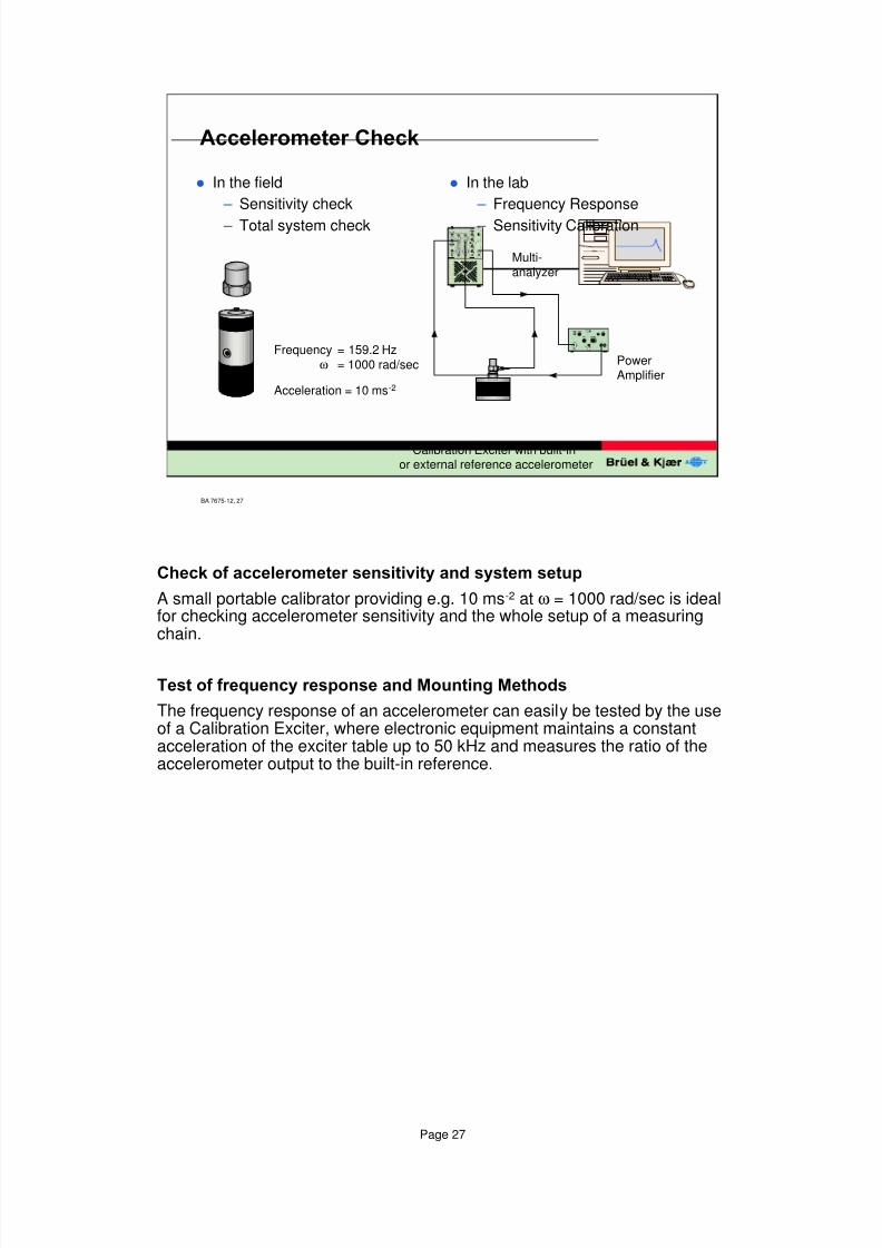
l In the field
– Sensitivity check
– Total system check
l In the lab
– Frequency Response
– Sensitivity Calibration
$FFHOHURPHWHU&KHFN
Frequency = 159.2 Hzω = 1000 rad/sec
Acceleration = 10 ms-2
PowerAmplifier
Multi-analyzer
Calibration Exciter with built-inor external reference accelerometer
&KHFNRIDFFHOHURPHWHUVHQVLWLYLW\DQGV\VWHPVHWXS
A small portable calibrator providing e.g. 10 ms-2 at ω = 1000 rad/sec is idealfor checking accelerometer sensitivity and the whole setup of a measuringchain.
7HVWRIIUHTXHQF\UHVSRQVHDQG0RXQWLQJ0HWKRGV
The frequency response of an accelerometer can easily be tested by the useof a Calibration Exciter, where electronic equipment maintains a constantacceleration of the exciter table up to 50 kHz and measures the ratio of theaccelerometer output to the built-in reference.
8/6/2019 Vibration Transducer B&K
http://slidepdf.com/reader/full/vibration-transducer-bk 28/38
Page 28
BA 7675-12, 28
0RXQWHG5HVRQDQFH7HVW
Charge
Accelerometer
Osc.
970071
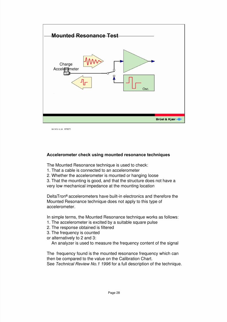
$FFHOHURPHWHUFKHFNXVLQJPRXQWHGUHVRQDQFHWHFKQLTXHV
The Mounted Resonance technique is used to check:
1. That a cable is connected to an accelerometer2. Whether the accelerometer is mounted or hanging loose
3. That the mounting is good, and that the structure does not have a
very low mechanical impedance at the mounting location
DeltaTron�accelerometers have built-in electronics and therefore the
Mounted Resonance technique does not apply to this type of
accelerometer.
In simple terms, the Mounted Resonance technique works as follows:
1. The accelerometer is excited by a suitable square pulse
2. The response obtained is filtered3. The frequency is counted
or alternatively to 2 and 3:
An analyzer is used to measure the frequency content of the signal
The frequency found is the mounted resonance frequency which can
then be compared to the value on the Calibration Chart.See 7HFKQLFDO5HYLHZ1Rfor a full description of the technique.
8/6/2019 Vibration Transducer B&K
http://slidepdf.com/reader/full/vibration-transducer-bk 29/38
Page 29
BA 7675-12, 29
&DOLEUDWLRQXVLQJ%DFNWREDFNPHWKRG
PowerAmplifier
Multi-analyzer
Shaker
ReferenceStandard
Accelerometer
Accelerometerunder test
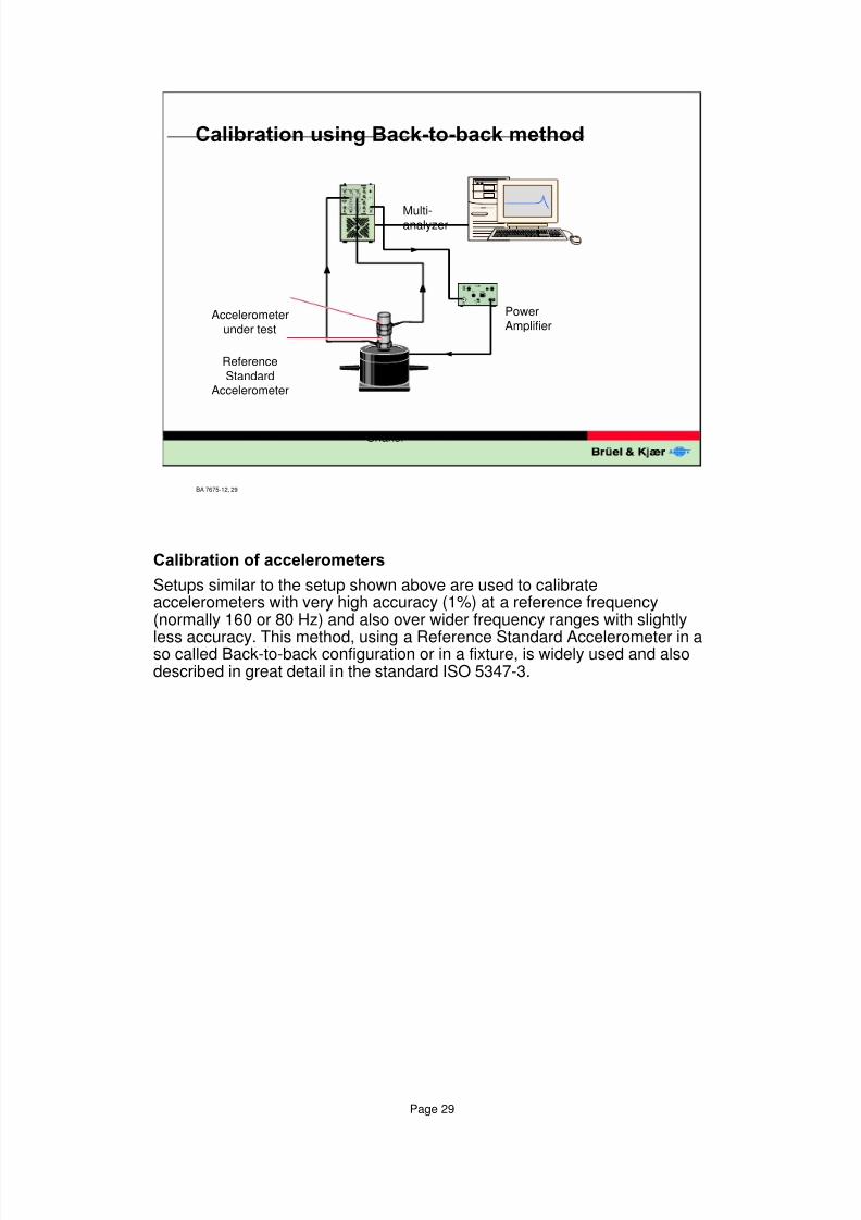
&DOLEUDWLRQRIDFFHOHURPHWHUV
Setups similar to the setup shown above are used to calibrateaccelerometers with very high accuracy (1%) at a reference frequency(normally 160 or 80 Hz) and also over wider frequency ranges with slightly
less accuracy. This method, using a Reference Standard Accelerometer in aso called Back-to-back configuration or in a fixture, is widely used and alsodescribed in great detail in the standard ISO 5347-3.
8/6/2019 Vibration Transducer B&K
http://slidepdf.com/reader/full/vibration-transducer-bk 30/38
Page 30
BA 7675-12, 30
3UHDPSOLILHU
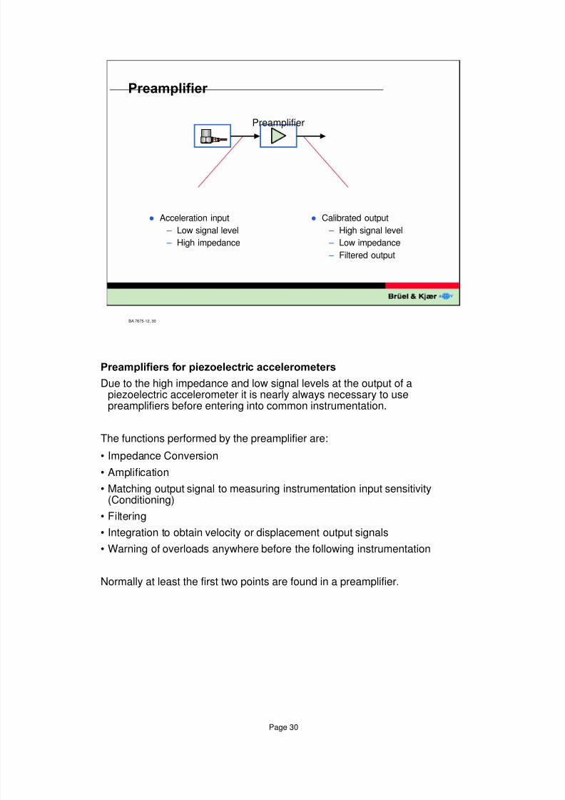
l Acceleration input
– Low signal level
– High impedance
l Calibrated output
– High signal level
– Low impedance
– Filtered output
Preamplifier
3UHDPSOLILHUVIRUSLH]RHOHFWULFDFFHOHURPHWHUV
Due to the high impedance and low signal levels at the output of apiezoelectric accelerometer it is nearly always necessary to usepreamplifiers before entering into common instrumentation.
The functions performed by the preamplifier are:
• Impedance Conversion
• Amplification
• Matching output signal to measuring instrumentation input sensitivity(Conditioning)
• Filtering
• Integration to obtain velocity or displacement output signals
• Warning of overloads anywhere before the following instrumentation
Normally at least the first two points are found in a preamplifier.
8/6/2019 Vibration Transducer B&K
http://slidepdf.com/reader/full/vibration-transducer-bk 31/38
Page 31
BA 7675-12, 31
&KRLFHRI3UHDPSOLILHU
9
4
10 pC/ms-2
10mV/ms-2 1mV/ms-2
9ROWDJH
3UHDPSOLILHU
&KDUJH
3UHDPSOLILHU
10 pC/ms-2
100 m
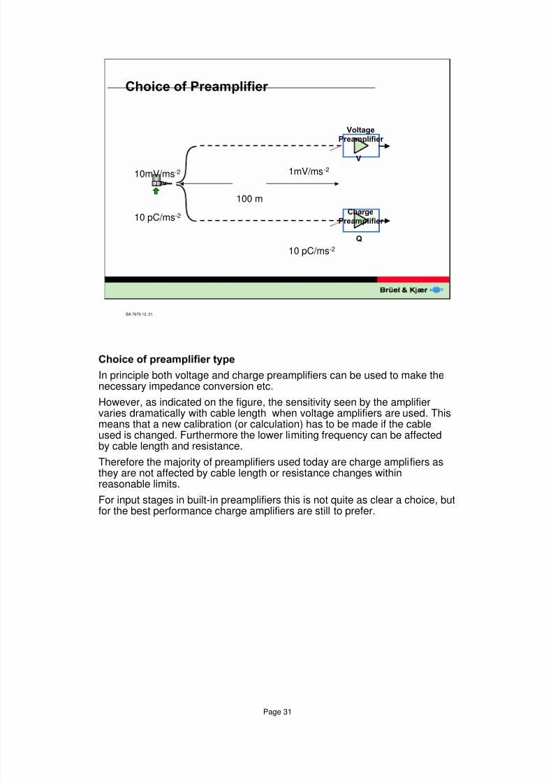
&KRLFHRISUHDPSOLILHUW\SH
In principle both voltage and charge preamplifiers can be used to make thenecessary impedance conversion etc.
However, as indicated on the figure, the sensitivity seen by the amplifier
varies dramatically with cable length when voltage amplifiers are used. Thismeans that a new calibration (or calculation) has to be made if the cableused is changed. Furthermore the lower limiting frequency can be affectedby cable length and resistance.
Therefore the majority of preamplifiers used today are charge amplifiers asthey are not affected by cable length or resistance changes withinreasonable limits.
For input stages in built-in preamplifiers this is not quite as clear a choice, butfor the best performance charge amplifiers are still to prefer.
8/6/2019 Vibration Transducer B&K
http://slidepdf.com/reader/full/vibration-transducer-bk 32/38
Page 32
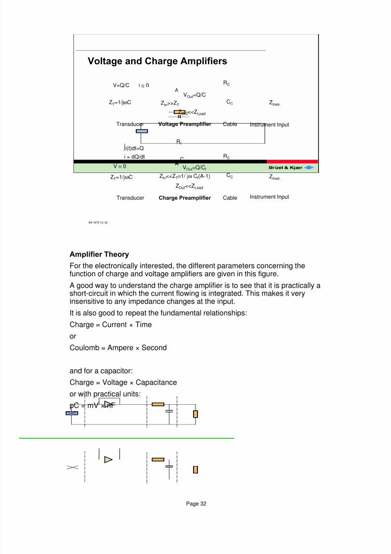
$PSOLILHU7KHRU\
For the electronically interested, the different parameters concerning thefunction of charge and voltage amplifiers are given in this figure.
A good way to understand the charge amplifier is to see that it is practically ashort-circuit in which the current flowing is integrated. This makes it veryinsensitive to any impedance changes at the input.
It is also good to repeat the fundamental relationships:
Charge = Current × Time
or
Coulomb = Ampere × Second
and for a capacitor:
Charge = Voltage × Capacitance
or with practical units:
pC = mV × nF
BA 7675-12, 32
9ROWDJHDQG&KDUJH$PSOLILHUV
A
Rf
Cf
V ≅ 0
ZT=1/jωC
&KDUJH3UHDPSOLILHU
ZIn<<ZT≅1/ jω Cf(A-1)
Cable
RC
CC
ZOut<<ZLoad
Transducer
i = dQ/dt
VOut=Q/Cf
∫ i(t)dt=Q
ZInstr.
Instrument Input
A
i ≅ 0V=Q/C
ZT=1/jωC
9ROWDJH3UHDPSOLILHU
ZIn>>ZT
Cable Instrument Input
RC
CC ZInstr.
ZOut<<ZLoad
Transducer
VOut=Q/C
A
8/6/2019 Vibration Transducer B&K
http://slidepdf.com/reader/full/vibration-transducer-bk 33/38
Page 33
BA 7675-12, 33
mV/ms-2
DeltaTron ®
Reference SensitivitymV/ms-2
DeltaTron ®
accelerometer
mV/ms-2
Constant CurrentLine-Driveamplifier
mV/pC
pC/ms-2 DeltaShear ®
accelerometer
930621
&DOLEUDWLRQ&KDUWIRU'HOWD7URQ ®
$FFHOHURPHWHU7\SH
6HULDO1R
5HIHUHQFH6HQVLWLYLW\ P9PV
RU P 9J
$FFHOHUDWLRQ5DQJH
7 & 7\ S PV SHD
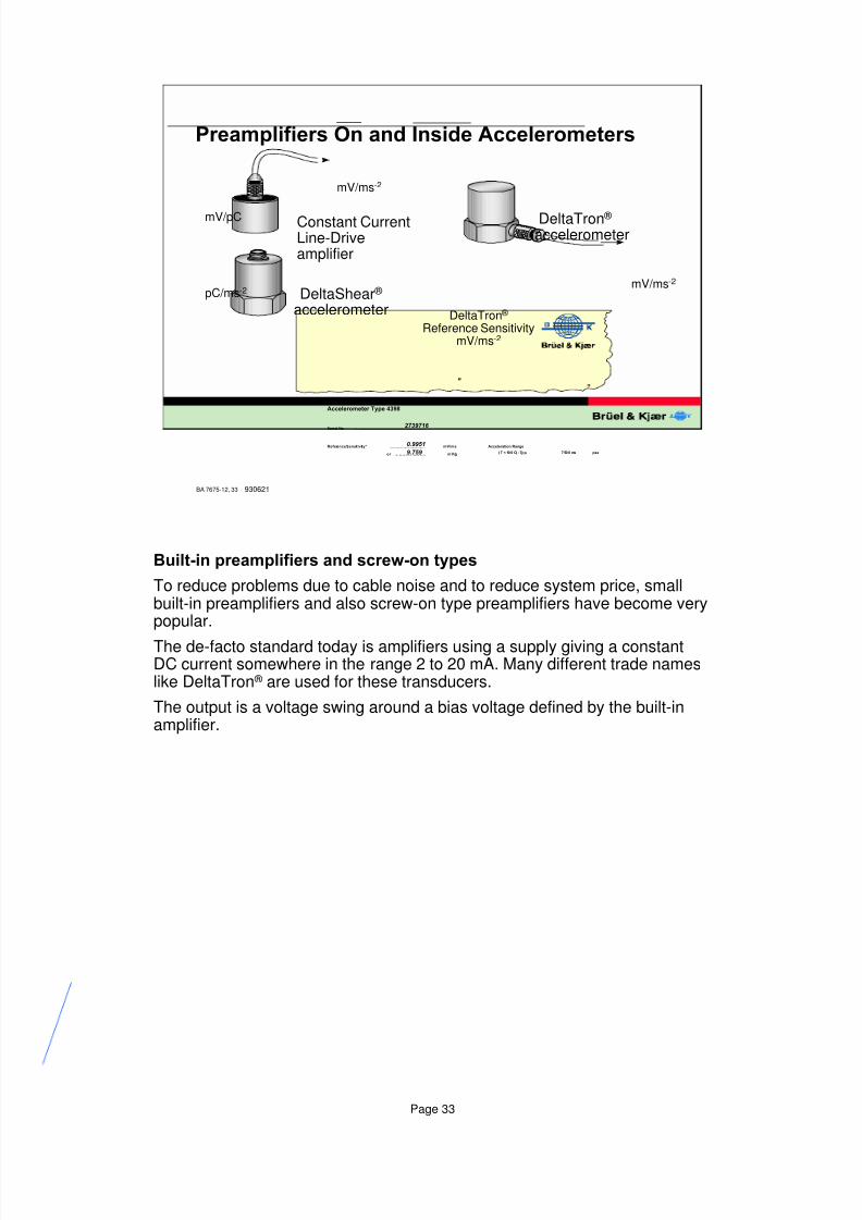
3UHDPSOLILHUV2QDQG,QVLGH$FFHOHURPHWHUV
%XLOWLQSUHDPSOLILHUVDQGVFUHZRQW\SHV
To reduce problems due to cable noise and to reduce system price, smallbuilt-in preamplifiers and also screw-on type preamplifiers have become verypopular.
The de-facto standard today is amplifiers using a supply giving a constantDC current somewhere in the range 2 to 20 mA. Many different trade nameslike DeltaTron ® are used for these transducers.
The output is a voltage swing around a bias voltage defined by the built-inamplifier.
8/6/2019 Vibration Transducer B&K
http://slidepdf.com/reader/full/vibration-transducer-bk 34/38
Page 34
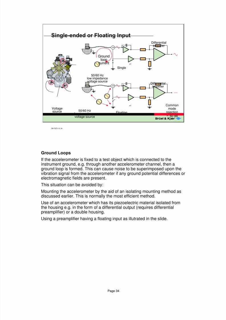
*URXQG/RRSV
If the accelerometer is fixed to a test object which is connected to theinstrument ground, e.g. through another accelerometer channel, then a
ground loop is formed. This can cause noise to be superimposed upon thevibration signal from the accelerometer if any ground potential differences orelectromagnetic fields are present.
This situation can be avoided by:
Mounting the accelerometer by the aid of an isolating mounting method asdiscussed earlier. This is normally the most efficient method.
Use of an accelerometer which has its piezoelectric material isolated fromthe housing e.g. in the form of a differential output (requires differentialpreamplifier) or a double housing.
Using a preamplifier having a floating input as illutrated in the slide.
BA 7675-12, 34
6LQJOHHQGHGRU)ORDWLQJ,QSXW
x1
x1
Groundloop
current
50/60 Hzlow impedancevoltage source
Differentialamplifier
50/60 Hzlow impedancevoltage source
Differentialamplifier
Single
Floating
Commonmode
rejection~ 50 dB
Voltage
source
8/6/2019 Vibration Transducer B&K
http://slidepdf.com/reader/full/vibration-transducer-bk 35/38
Page 35
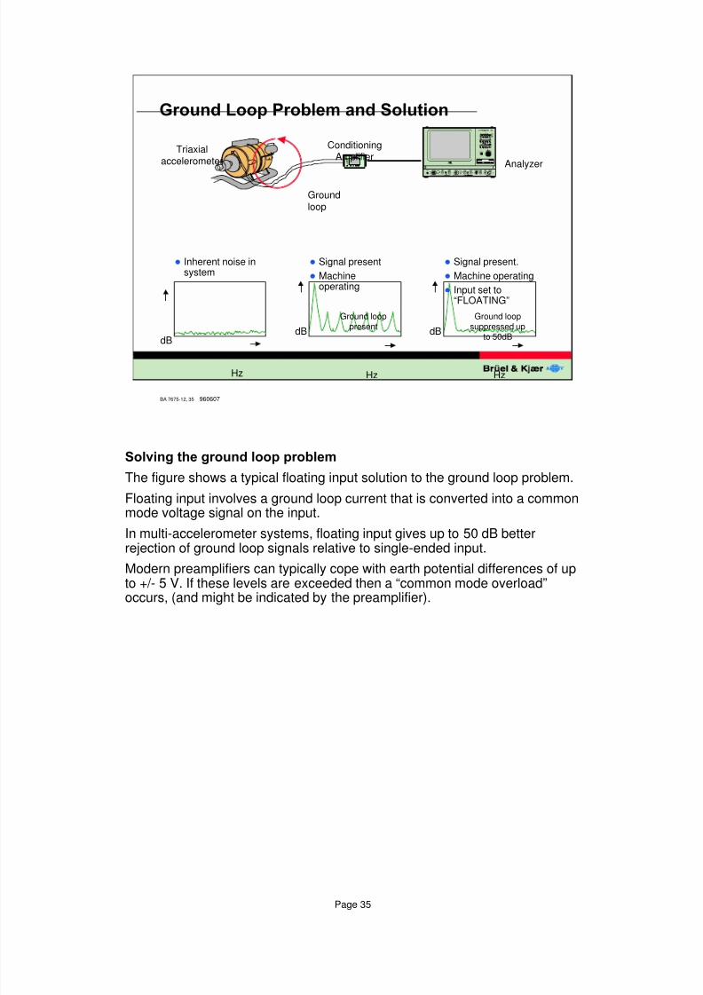
6ROYLQJWKHJURXQGORRSSUREOHP
The figure shows a typical floating input solution to the ground loop problem.
Floating input involves a ground loop current that is converted into a commonmode voltage signal on the input.
In multi-accelerometer systems, floating input gives up to 50 dB betterrejection of ground loop signals relative to single-ended input.
Modern preamplifiers can typically cope with earth potential differences of upto +/- 5 V. If these levels are exceeded then a “common mode overload”occurs, (and might be indicated by the preamplifier).
BA 7675-12, 35 960607
*URXQG/RRS3UREOHPDQG6ROXWLRQ
Triaxialaccelerometer
ConditioningAmplifier
Analyzer
Hz HzHz
dBdB dB
l Inherent noise insystem
l Signal present
l Machineoperating
l Signal present.
l Machine operating
l Input set to“FLOATING”
8 � � q v � v � � v � t à 6 � � y v s v r �
1 ( ; 8 6
7 � r y Ã É Ã F w �
P � r � y � h q
Groundloop
Ground looppresent
Ground loopsuppressed up
to 50dB
8/6/2019 Vibration Transducer B&K
http://slidepdf.com/reader/full/vibration-transducer-bk 36/38
Page 36
BA 7675-12, 36
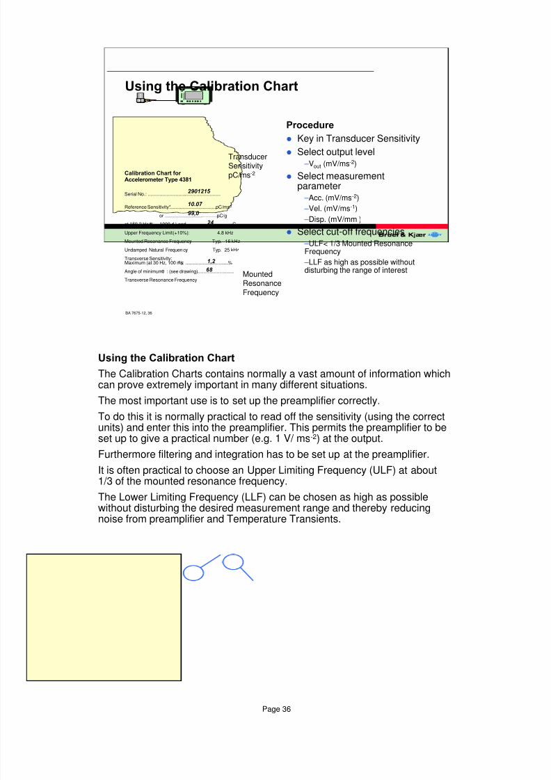
8VLQJWKH&DOLEUDWLRQ&KDUW
8 � � q v � v � � v � t à 6 � � y v s v r �
1 ( ; 8 6
7 � r y Ã É Ã F w
P � r � y � h q
&DOLEUDWLRQ&KDUWIRU $FFHOHURPHWHU7\SH
Serial No.: .......................................................
Reference Sensitivity*....................................pC/ms2
or ...........................................pC/g
at 159.2 Hz (w = 1000 s1 ) and ................................C
Upper Frequency Limit (+10%): 4.8 kHz
Mounted Resonance Frequency: Typ. 16 kHz
Undamped Natural Frequency: Typ. 25 kHz
Transverse Sensitivity:Maximum (at 30 Hz, 100 ms2 ): ..................................%
Angle of minimum,a : (see drawing)............................ Transverse Resonance Frequency:
TransducerSensitivitypC/ms-2
MountedResonanceFrequency
3URFHGXUH
l Key in Transducer Sensitivityl Select output level
– Vout (mV/ms-2)
l Select measurementparameter
– Acc. (mV/ms-2)
– Vel. (mV/ms-1)
– Disp. (mV/mm )
l Select cut-off frequencies – ULF< 1/3 Mounted ResonanceFrequency
– LLF as high as possible without
disturbing the range of interest
8VLQJWKH&DOLEUDWLRQ&KDUW
The Calibration Charts contains normally a vast amount of information whichcan prove extremely important in many different situations.
The most important use is to set up the preamplifier correctly.
To do this it is normally practical to read off the sensitivity (using the correctunits) and enter this into the preamplifier. This permits the preamplifier to beset up to give a practical number (e.g. 1 V/ ms-2) at the output.
Furthermore filtering and integration has to be set up at the preamplifier.
It is often practical to choose an Upper Limiting Frequency (ULF) at about1/3 of the mounted resonance frequency.
The Lower Limiting Frequency (LLF) can be chosen as high as possiblewithout disturbing the desired measurement range and thereby reducingnoise from preamplifier and Temperature Transients.
8/6/2019 Vibration Transducer B&K
http://slidepdf.com/reader/full/vibration-transducer-bk 37/38
Page 37
BA 7675-12, 37
&RQFOXVLRQ
This lecture should provide you with sufficientinformation to:
l Select and use the right transducers for yourmeasurements
l Select and use preamplifiers for your transducers
l Set-up a working measurement chain
l Avoid general problems like ground loops
8/6/2019 Vibration Transducer B&K
http://slidepdf.com/reader/full/vibration-transducer-bk 38/38
BA 7675-12, 38
/LWHUDWXUHIRU)XUWKHU5HDGLQJ
l Piezoelectric Accelerometers and Vibration Preamplifiers(Brüel & Kjær Theory and Application Handbook BB 0694-12)
l Shock and Vibration Handbook (Harris and Crede, McGraw-Hill 1976)
l ISO 5347 - Methods for Calibration and Characterization ofVibration and Shock Transducers
l Brüel & Kjær Technical Review
– No.1 - 1996 (BV 0048-11)


![Research Article Research of Jiles-Atherton Dynamic Model ...Giant magnetostrictive materials (GMM) are widely used in transducer, precision actuator, and active vibration [ ] because](https://img.pdfslide.us/doc/110x75/60d35234734d137df32c4e5b/research-article-research-of-jiles-atherton-dynamic-model-giant-magnetostrictive.jpg)