Embed Size (px)
Citation preview
BO 0179-12
FIXTURES FOR B & K VIBRATION EXCITERS
Revised October 1987
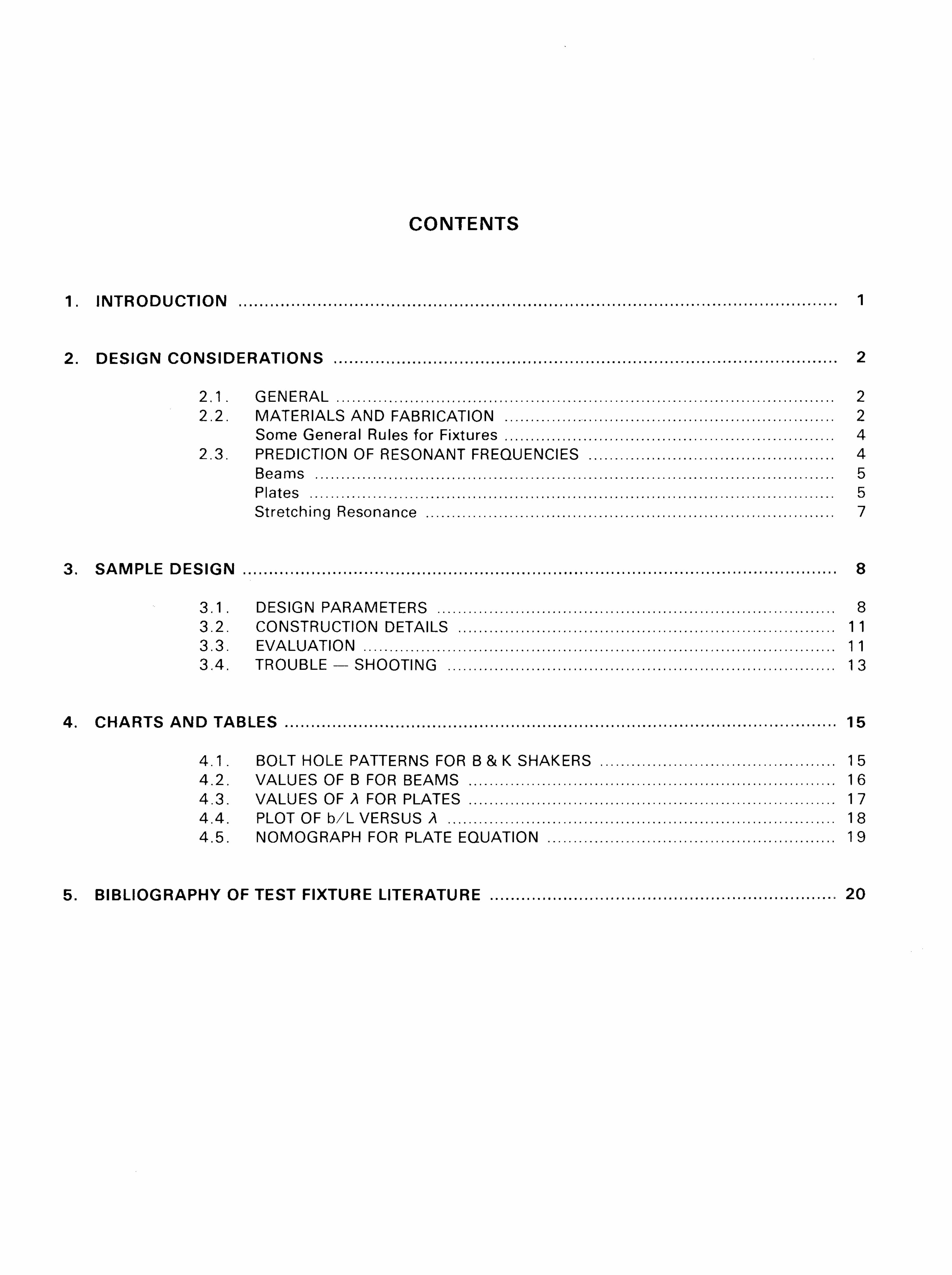
CONTENTS
1. INTRODUCTION 1
2. DESIGN CONSIDERATIONS 2
2 .1 . GENERAL 2 2.2. MATERIALS AND FABRICATION 2
Some General Rules for Fixtures 4 2.3. PREDICTION OF RESONANT FREQUENCIES 4
Beams 5 Plates 5 Stretching Resonance 7
3. SAMPLE DESIGN 8
3.1 . DESIGN PARAMETERS 8 3.2. CONSTRUCTION DETAILS 11 3.3. EVALUATION 11 3.4. TROUBLE — SHOOTING 13
4. CHARTS AND TABLES 15
4 . 1 . BOLT HOLE PATTERNS FOR B & K SHAKERS 15 4.2. VALUES OF B FOR BEAMS 16 4.3. VALUES OF A FOR PLATES 17 4.4. PLOT OF b/L VERSUS A 18 4.5. NOMOGRAPH FOR PLATE EQUATION 19
5. BIBLIOGRAPHY OF TEST FIXTURE LITERATURE 20
1. INTRODUCTION
The design and construction of fixtures can be a very complicated undertaking, as a look at some of the literature wi l l show. Some f irms and research organizations keep a fu l l -t ime staff of qualified engineers occupied wi th nothing but designing fixtures. Indeed, when the test involves a large airborne radar unit which must be tested at several g in the frequency range from 10 to 2 0 0 0 Hz, the design of the pertinent fixture is a job for an expert.
However, we have found that many of our customers have neither the staff nor the experience for this kind of work, and quite often only need a simple general purpose fixture to handle all their testing needs.
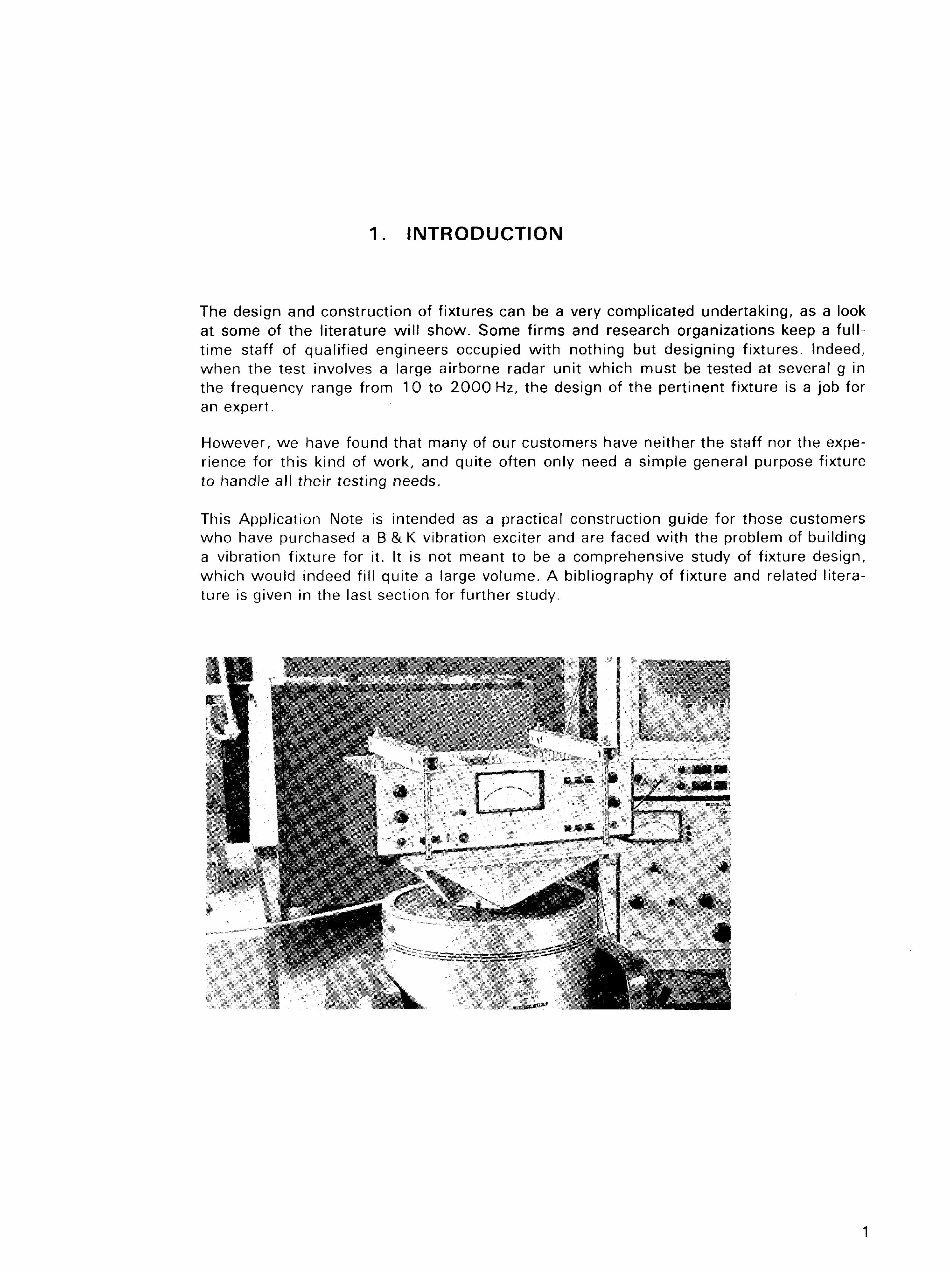
This Application Note is intended as a practical construction guide for those customers who have purchased a B & K vibration exciter and are faced wi th the problem of building a vibration fixture for it. It is not meant to be a comprehensive study of f ixture design, which would indeed fil l quite a large volume. A bibliography of f ixture and related literature is given in the last section for further study.
1
2. DESIGN CONSIDERATIONS
2 . 1 . GENERAL
The basic idea wi th any fixture is that it should transmit uniformly the forces produced by the vibration exciter to the test object. It is generally impossible to fix a test object directly to the shaker table itself, and the fixture acts as a transition piece between the two.
In B & K vibration exciters, the force from the driver coil is transmitted via the skeleton to the four mounting holes at each corner of the table. The object to be tested usually has a number of finite points (feet, mounting brackets, screw holes) where the force is to be applied, the idea being to duplicate as nearly as possible the force input experienced in service. Between the table and the test object is the f ixture. In order to get the most out of the vibration exciter, this fixture should carry the force from the four mounting holes in the table to the mounting points on the test object wi th a min imum of loss and distortion. In other words the fixture should be as rigid as possible. This is condition number one in fixture design.
The acceleration level possible wi th the vibration exciter is inversely proportional to the total mass it has to drive, therefore the fixture should be as light as possible. This is condition number two. An ideal f ixture, then, would have infinite stiffness at all frequencies and zero mass, and it is this paradox which is the basis of fixture design.
Although a f ixturing problem may seem very complicated, in fact many of the design parameters are determined before-hand. The weight, for instance, is l imited by the weight of the test object and the force available from the exciter. The shape is determined in part by the fact that it has to fit the exciter table at its bottom surface and the test object at one of its other surfaces. Finally, the test conditions impose restrictions on the fixture. A typical test specification calls for testing to 2 0 0 0 Hz wi th no fixture resonances below 1 0 0 0 Hz and an allowable variation in vibration levels between 1 and 2 kHz of not more than 2 ; 1 between any pair of points on the table.
2.2. MATERIALS A N D FABRICATION
Of the materials generally considered for fixture construction, steel, a luminum and magnesium are the most common. For very small items, beryll ium is sometimes used, but its very high strength and light weight are counteracted by its cost and difficulty in machining.
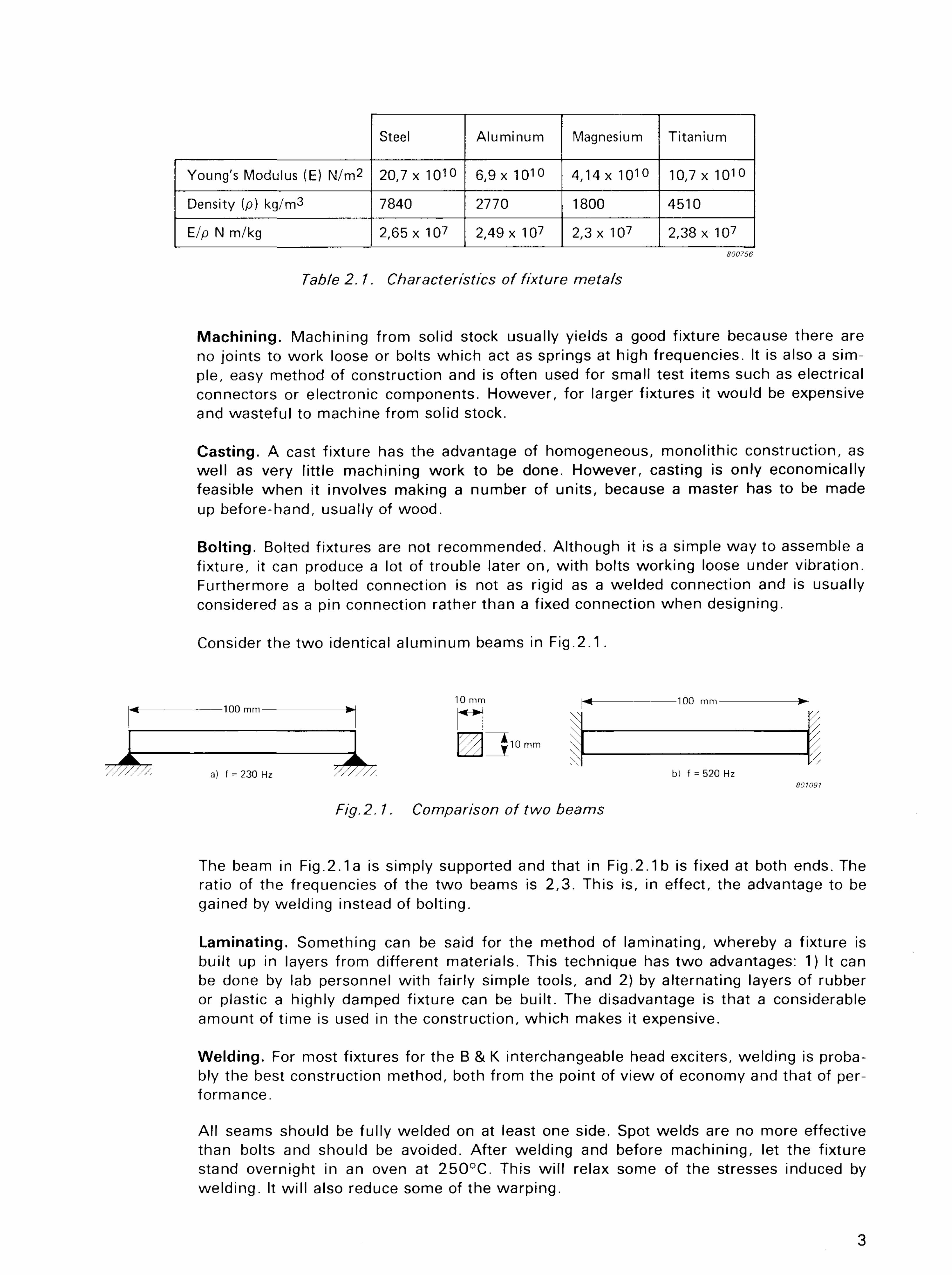
The ratio of Young's Modulus to density (E/p) is a controll ing factor for the natural frequency of a construction, and since this ratio is roughly the same for steel, a luminum and magnesium, the choice of material wi l l not greatly affect the natural frequency of the f ixture. It w i l l , however, in the case of steel, affect the weight, and in the case of magnesium, the cost. Table 2.1 compares the E, p and E/p of the three metals. Titanium, used in B & K accelerometers, is included for comparison.
There are numerous ways to fabricate a fixture; among them, machining the fixture out of one solid piece of material, casting, bolting together several pieces to form an assembly, building up an assembly by laminating strips of material together, and welding.
2
Steel Aluminum Magnesium Titanium
Young's Modulus (E) N/m2 20,7 x 1CH0 6,9 x 10¹⁰ 4,14 x 10 1 0 10,7 x 10¹⁰
Density (p) kg/m3 7840 2770 1800 4510
E/p N m/kg 2,65 x 10⁷ 2,49 x 10⁷ 2,3 x 10⁷ 2,38 x 10⁷
800756
Table 2.1. Characteristics of fixture metals
Machining. Machining from solid stock usually yields a good fixture because there are no joints to work loose or bolts which act as springs at high frequencies. It is also a simple, easy method of construction and is often used for small test items such as electrical connectors or electronic components. However, for larger fixtures it would be expensive and wasteful to machine from solid stock.
Casting. A cast f ixture has the advantage of homogeneous, monolithic construction, as wel l as very little machining work to be done. However, casting is only economically feasible when it involves making a number of units, because a master has to be made up before-hand, usually of wood.
Bolting. Bolted fixtures are not recommended. Although it is a simple way to assemble a f ixture, it can produce a lot of trouble later on, wi th bolts working loose under vibration. Furthermore a bolted connection is not as rigid as a welded connection and is usually considered as a pin connection rather than a fixed connection when designing.
Consider the two identical aluminum beams in F ig .2 .1 .
Fig.2.1. Comparison of two beams
The beam in Fig.2.1a is simply supported and that in Fig.2.1b is fixed at both ends. The ratio of the frequencies of the two beams is 2,3. This is, in effect, the advantage to be gained by welding instead of bolting.
Laminating. Something can be said for the method of laminating, whereby a fixture is built up in layers from different materials. This technique has two advantages: 1) It can be done by lab personnel wi th fairly simple tools, and 2) by alternating layers of rubber or plastic a highly damped fixture can be built. The disadvantage is that a considerable amount of t ime is used in the construction, which makes it expensive.
Welding. For most fixtures for the B & K interchangeable head exciters, welding is probably the best construction method, both from the point of view of economy and that of performance.
All seams should be fully welded on at least one side. Spot welds are no more effective than bolts and should be avoided. After welding and before machining, let the fixture stand overnight in an oven at 250°C. This wi l l relax some of the stresses induced by welding. It wi l l also reduce some of the warping.
3
To compensate for this warping, the top plate of the fixture should be made thicker than the design thickness, then machined down to the design thickness after annealing.
Wooden Fixtures. It should also be noted here that wooden fixtures have been used successfully at low frequencies and that a reasonable fixture can be made of laminated wood, which has a high damping coefficient.
2 . 2 . 1 . Some General Rules for Fixtures
1. The easiest and cheapest fixture for the B & K interchangeable head exciters is that made of welded aluminum plate.
2. The mating surfaces of the fixture should be machined as flat as possible. If the surface is a plate, the fabrication thickness should be greater than the design thickness as some warping wi l l occur during fabrication which can later be machined off.
3. All seams should be ful l welded on at least one side. Avoid spot welds and bolts.
4. Attachment bolts from fixture to exciter table should be counter-sunk so that the stressed length of the bolt is twice the diameter.
5. It is very difficult to eliminate resonances completely in the frequency range 1000 — 2 0 0 0 Hz. What can be done, however, is to introduce some damping into the structure in order to reduce the severity of the resonance. This may be done by bonding a damping material onto the member in question or fitting rubber or wooden blocks between resonating plates. Hollow fixtures may be pumped full of polyure-thene foam.
6. Make a dril l ing template to match the threaded holes in the shaker table. This insures proper alignment of the bolts.
7. Tighten all the bolts as hard as the limiting torque of the inserts wil l al low.
2.3 . PREDICTION OF RESONANT FREQUENCIES
The load carrying ability of the material almost never enters into fixture design. This is because, if the structure is designed so as to avoid resonances, it is over-designed by far wi th respect to static or dynamic loading. The resonant frequency then becomes the cri t i cal design factor.
The prediction of natural frequencies of a structure can be very complicated. However, for the purpose of designing a f ixture, only the first natural frequency is important. The first natural frequency is the most damaging and the appearance of any resonances wi l l often disqualify a fixture for use.
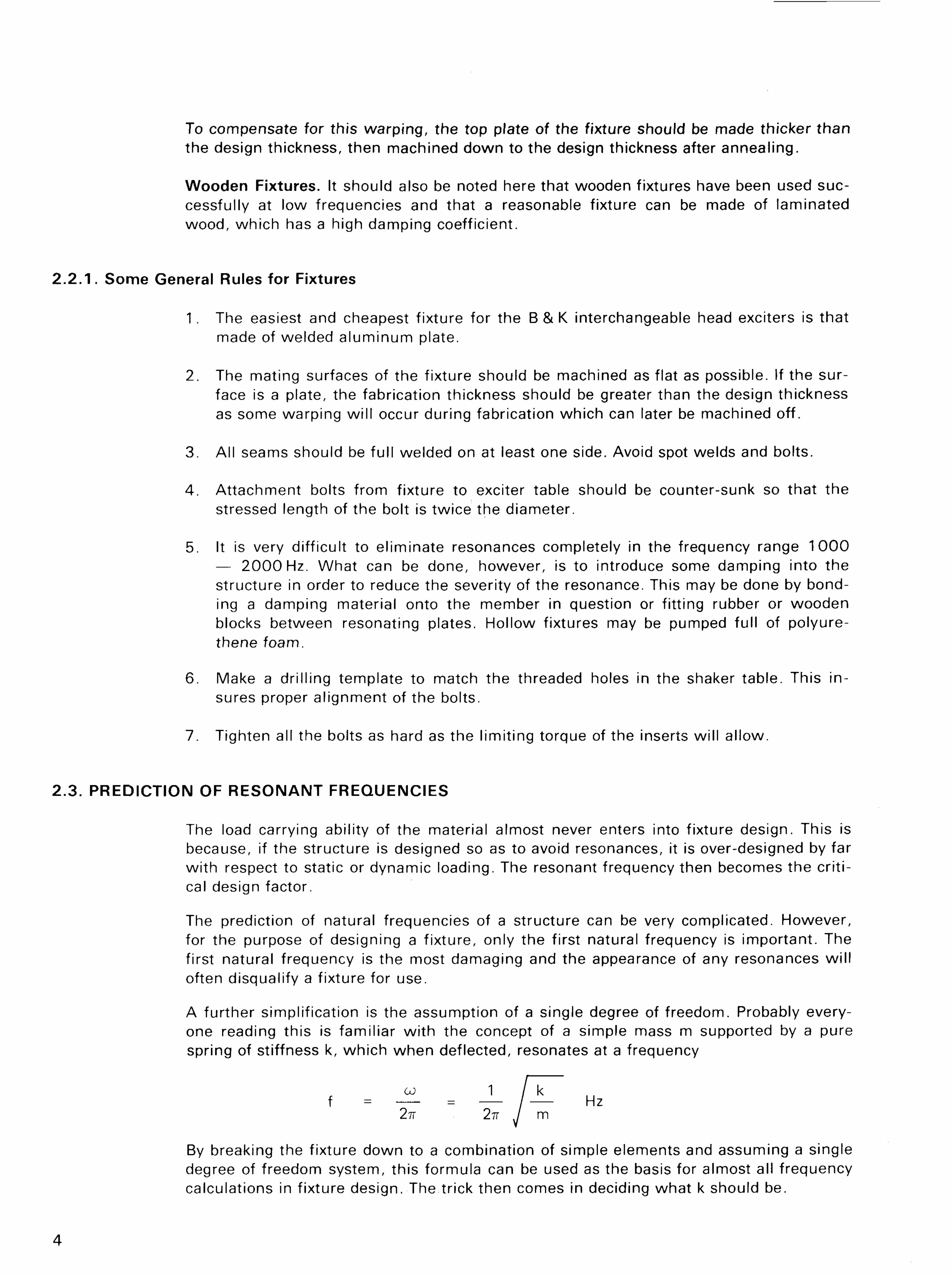
A further simplification is the assumption of a single degree of freedom. Probably everyone reading this is familiar wi th the concept of a simple mass m supported by a pure spring of stiffness k, which when deflected, resonates at a frequency
f - -^ - -1_ / J T Hz
By breaking the fixture down to a combination of simple elements and assuming a single degree of freedom system, this formula can be used as the basis for almost all frequency calculations in fixture design. The trick then comes in deciding what k should be.
4
2 . 3 . 1 . Beams
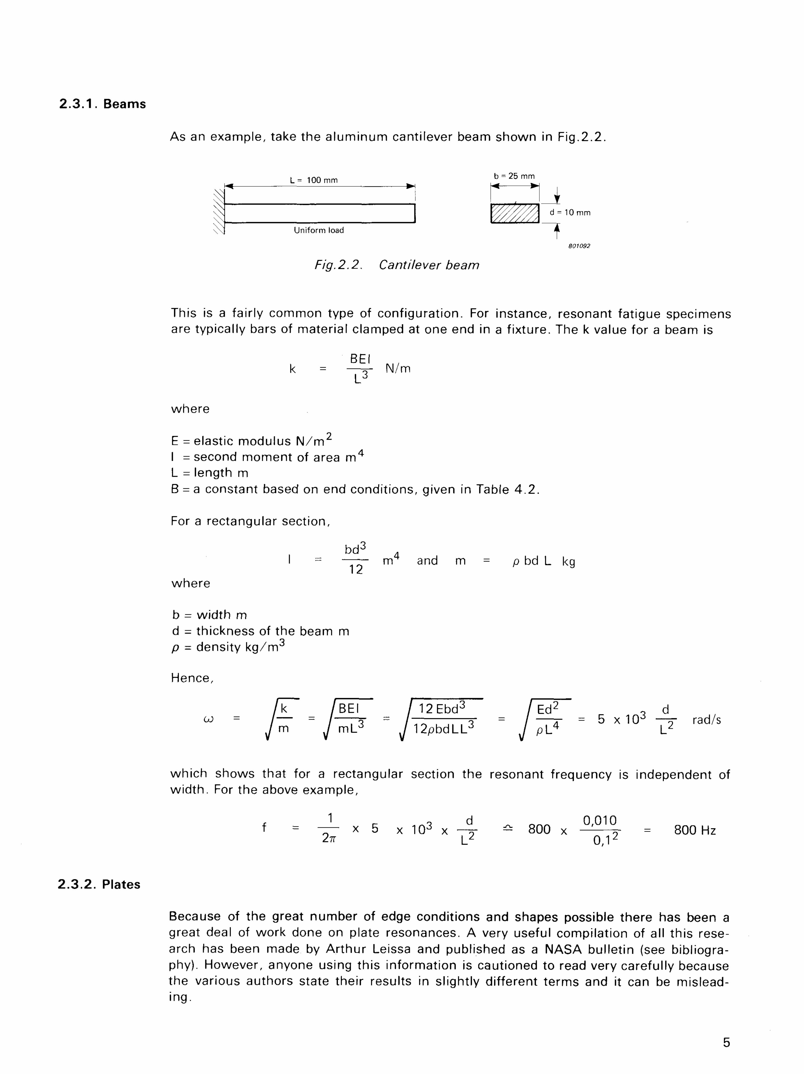
As an example, take the aluminum cantilever beam shown in Fig.2.2.
Fig.2.2. Cantilever beam
This is a fairly common type of configuration. For instance, resonant fatigue specimens are typically bars of material clamped at one end in a fixture. The k value for a beam is
BEI k = —~- N/m
L3
where E = elastic modulus N / m 2
I = second moment of area m 4
L = length m B = a constant based on end conditions, given in Table 4.2.
For a rectangular section,
bd 3 d
I = —— nv and m = p bd L kg
where
b = width m d = thickness of the beam m p = density k g / m 3
Hence,
fiT /BEI / 12Ebd3 / E d 2 ~ d co = / — = /—-pr - / — T = / — r = 5 x 10³ - o - rad/s
ym J mL3 yi2pbdLL3 J pL4 L2
which shows that for a rectangular section the resonant frequency is independent of width. For the above example,
f = — * 5 x 1 0 3 x —«■ - 800 x — = 800 Hz 2TT L 2 0 , 1 2
2.3.2. Plates
Because of the great number of edge conditions and shapes possible there has been a great deal of work done on plate resonances. A very useful compilation of all this research has been made by Arthur Leissa and published as a NASA bulletin (see bibliography). However, anyone using this information is cautioned to read very carefully because the various authors state their results in slightly different terms and it can be misleading.
5
Most plate formulae are based on the work of Warburton, who used the Rayleigh-Ritz method of equating kinetic and potential energy and evolved a formula for resonant frequency.
For a plate:
? 7T4 D o E h 3
co = —A A , where D = —- 0 b 4 p h 12 (1 -v2)
where
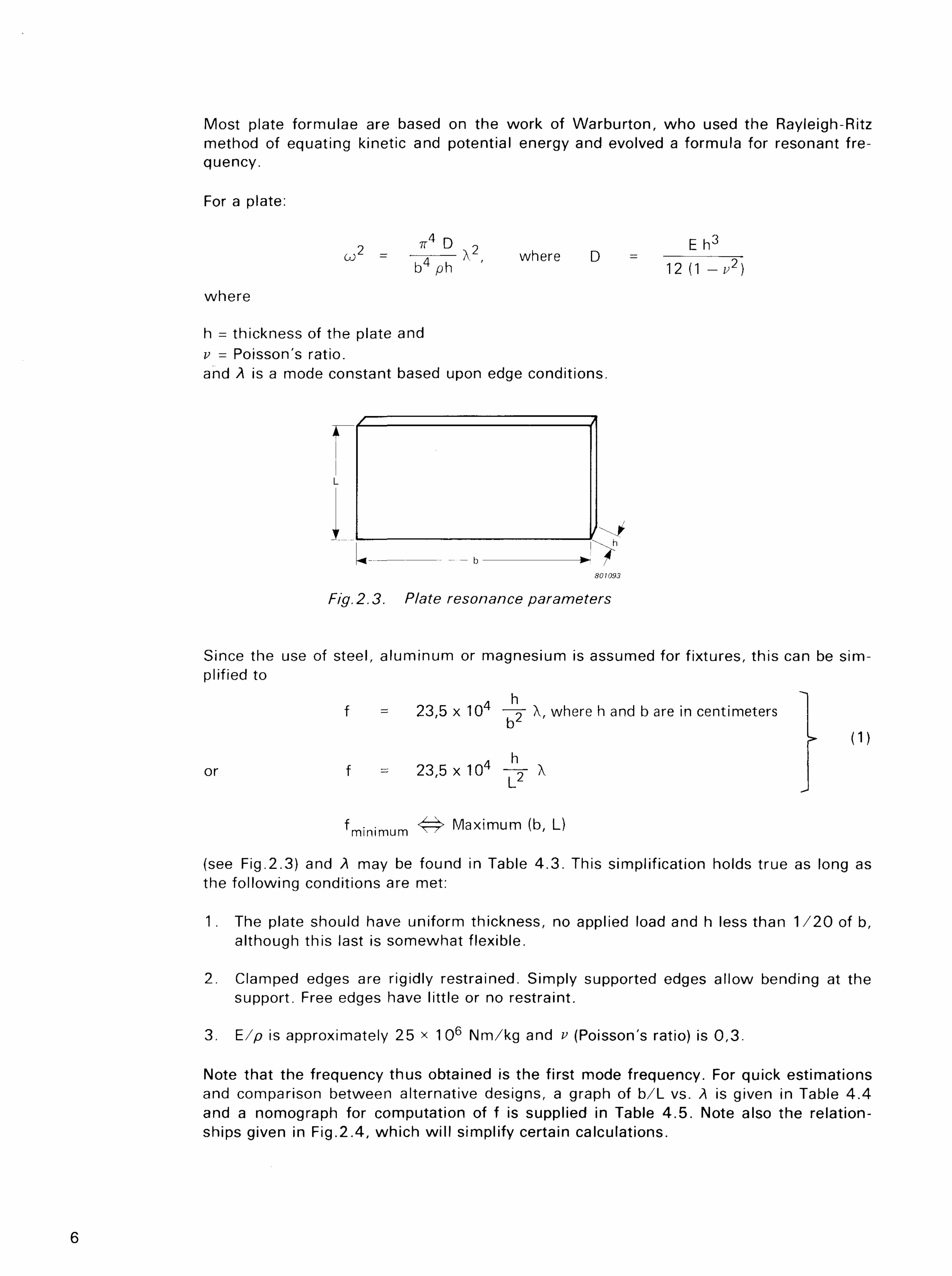
h = thickness of the plate and v - Poisson's ratio. and A is a mode constant based upon edge conditions.
Fig. 2.3. Piate resonance parameters
Since the use of steel, a luminum or magnesium is assumed for f ixtures, this can be simplified to
A h f = 23,5 x 10 —n- A, where h and b are in centimeters
b2
(D A h
or f = 23,5 x 10⁴ —?- X L
fminimum ^ Maximum <b, L)
(see Fig.2.3) and A may be found in Table 4 .3 . This simplification holds true as long as the fol lowing conditions are met:
1. The plate should have uniform thickness, no applied load and h less than 1 / 2 0 of b, although this last is somewhat flexible.
2. Clamped edges are rigidly restrained. Simply supported edges allow bending at the support. Free edges have little or no restraint.
3. E/p is approximately 25 x 1 0 6 Nm/kg and v (Poisson's ratio) is 0,3.
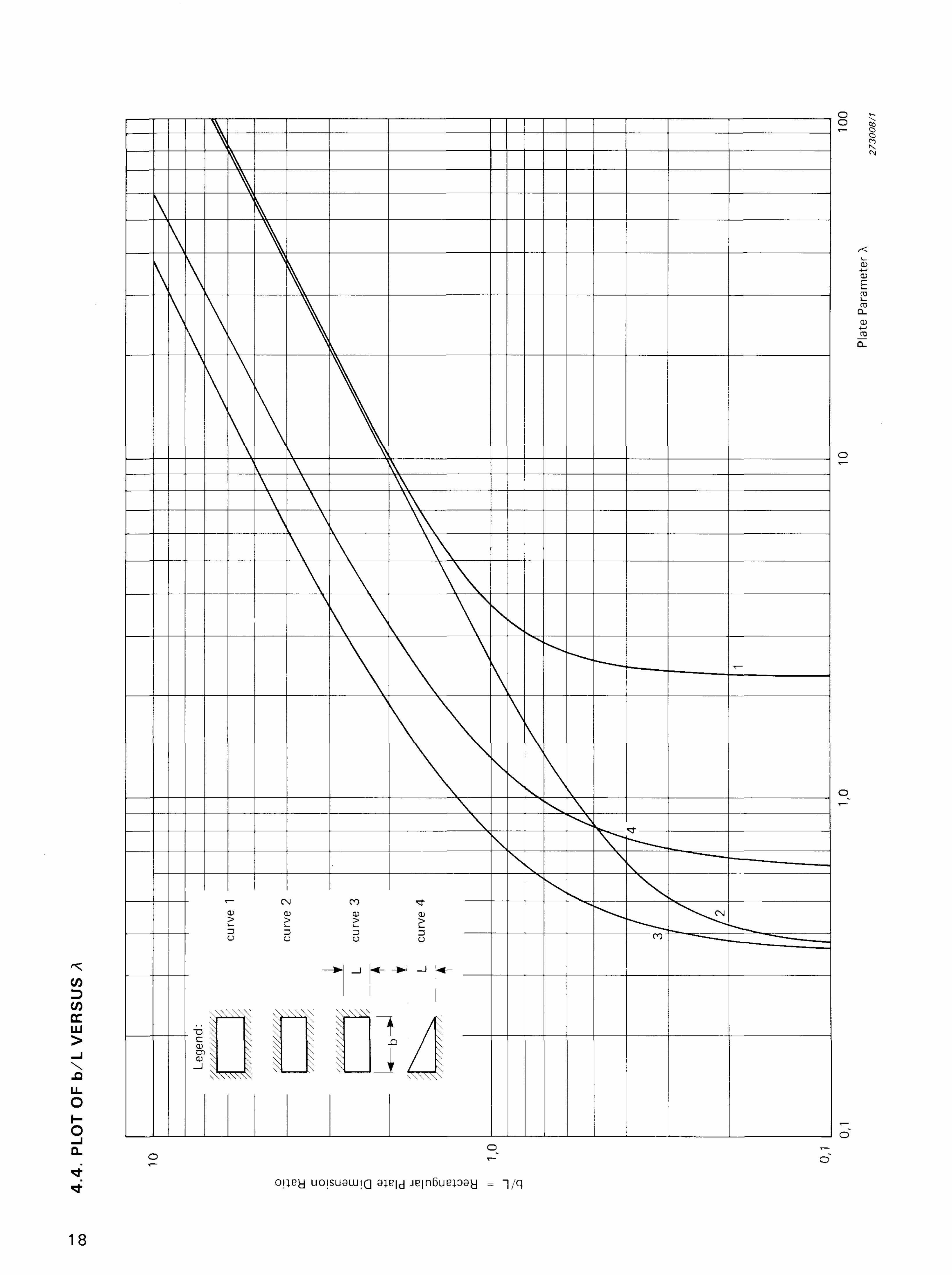
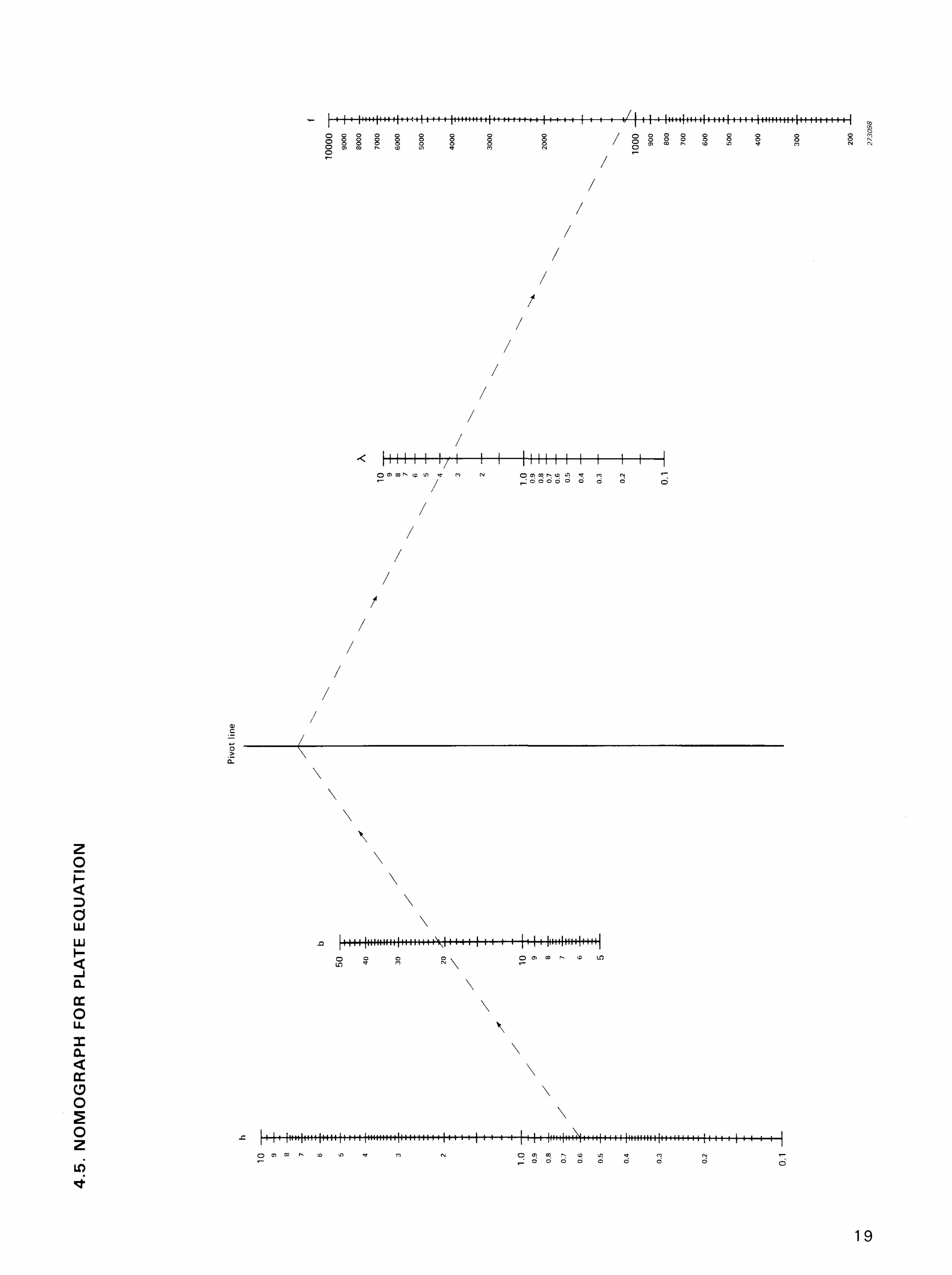
Note that the frequency thus obtained is the first mode frequency. For quick estimations and comparison between alternative designs, a graph of b/L vs. A is given in Table 4 .4 and a nomograph for computation of f is supplied in Table 4 .5 . Note also the relationships given in Fig.2.4, which wi l l simplify certain calculations.
6
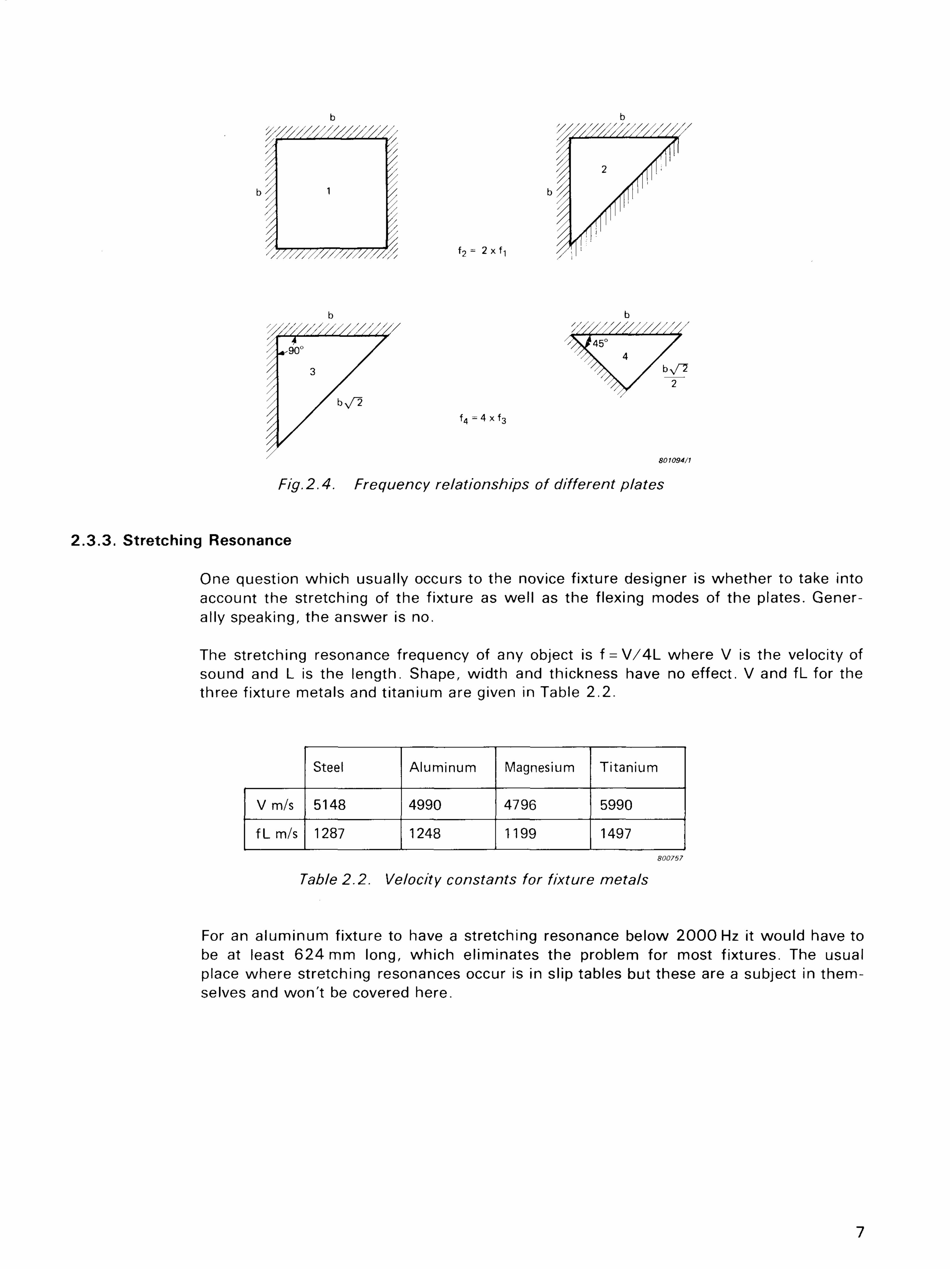
Fig.2.4. Frequency relationships of different plates
2.3.3 . Stretching Resonance
One question which usually occurs to the novice fixture designer is whether to take into account the stretching of the fixture as well as the flexing modes of the plates. Generally speaking, the answer is no.
The stretching resonance frequency of any object is f = V / 4 L where V is the velocity of sound and L is the length. Shape, width and thickness have no effect. V and fl_ for the three fixture metals and t i tanium are given in Table 2.2.
For an aluminum fixture to have a stretching resonance below 2 0 0 0 Hz it would have to be at least 624 mm long, which eliminates the problem for most f ixtures. The usual place where stretching resonances occur is in slip tables but these are a subject in themselves and won' t be covered here.
7
Steel Aluminum Magnesium Titanium
V m/s 5148 4990 4796 5990
fLm/s 1287 1248 1199 1497 80075?
3. SAMPLE DESIGN
As an il lustration of the foregoing principles we wi l l design a general purpose fixture which wi l l fit a Type 481 3 or 481 7 Exciter Head. The requirements are:
a. It must have a working surface 4 0 0 mm square. b. It must have no resonances below 1000 Hz.
3 . 1 . DESIGN PARAMETERS
As in most cases, the dimensions of the f ixture are pretty much predetermined. The top surface wi l l measure 4 0 0 mm x 4 0 0 mm. The bottom surface (see Table 4.1) wi l l measure 1 00 mm x 1 0 0 mm. If we simply mounted a plate on the shaker table it would have to be quite thick and therefore heavy and would obstruct the movement of the table on the downstroke. If we make the fixture very high, any off-centre weight in the test object wi l l cause rocking. So we choose a height of 100 mm as reasonable and set the top plate atop a 1 00 mm cube.
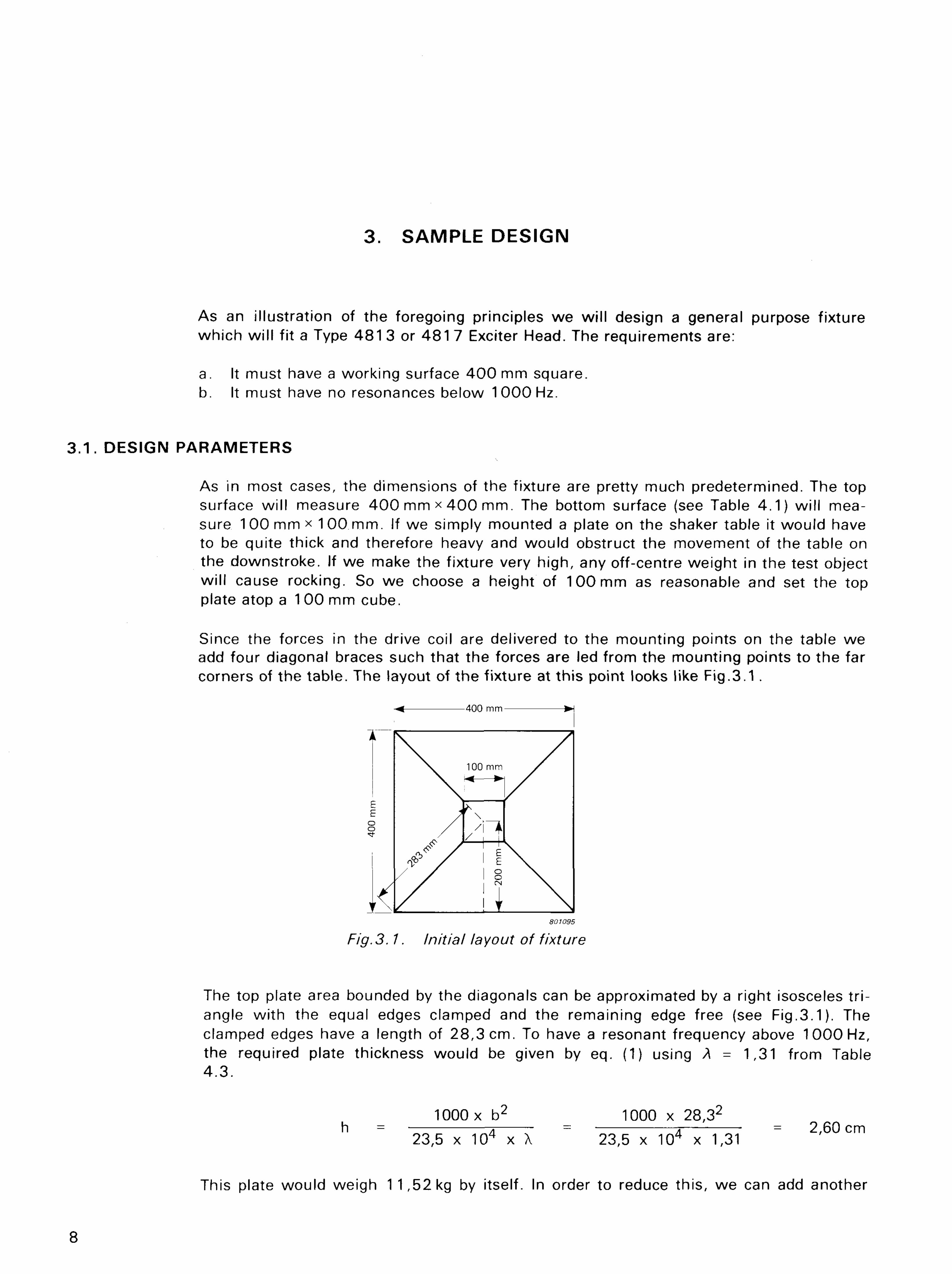
Since the forces in the drive coil are delivered to the mounting points on the table we add four diagonal braces such that the forces are led from the mounting points to the far corners of the table. The layout of the f ixture at this point looks like Fig.3.1 .
Fig. 3.1. Initial layout of fixture
The top plate area bounded by the diagonals can be approximated by a right isosceles t r i angle wi th the equal edges clamped and the remaining edge free (see Fig.3.1). The clamped edges have a length of 28,3 cm. To have a resonant frequency above 1000 Hz, the required plate thickness would be given by eq. (1) using A = 1,31 from Table 4 .3 .
1000x b2 1000 x 28,32
h = 2. = A * = 2,60 cm 23,5 x 104 x X 23,5 x 104 x 1,31
This plate would weigh 1 1,52 kg by itself. In order to reduce this, we can add another
8
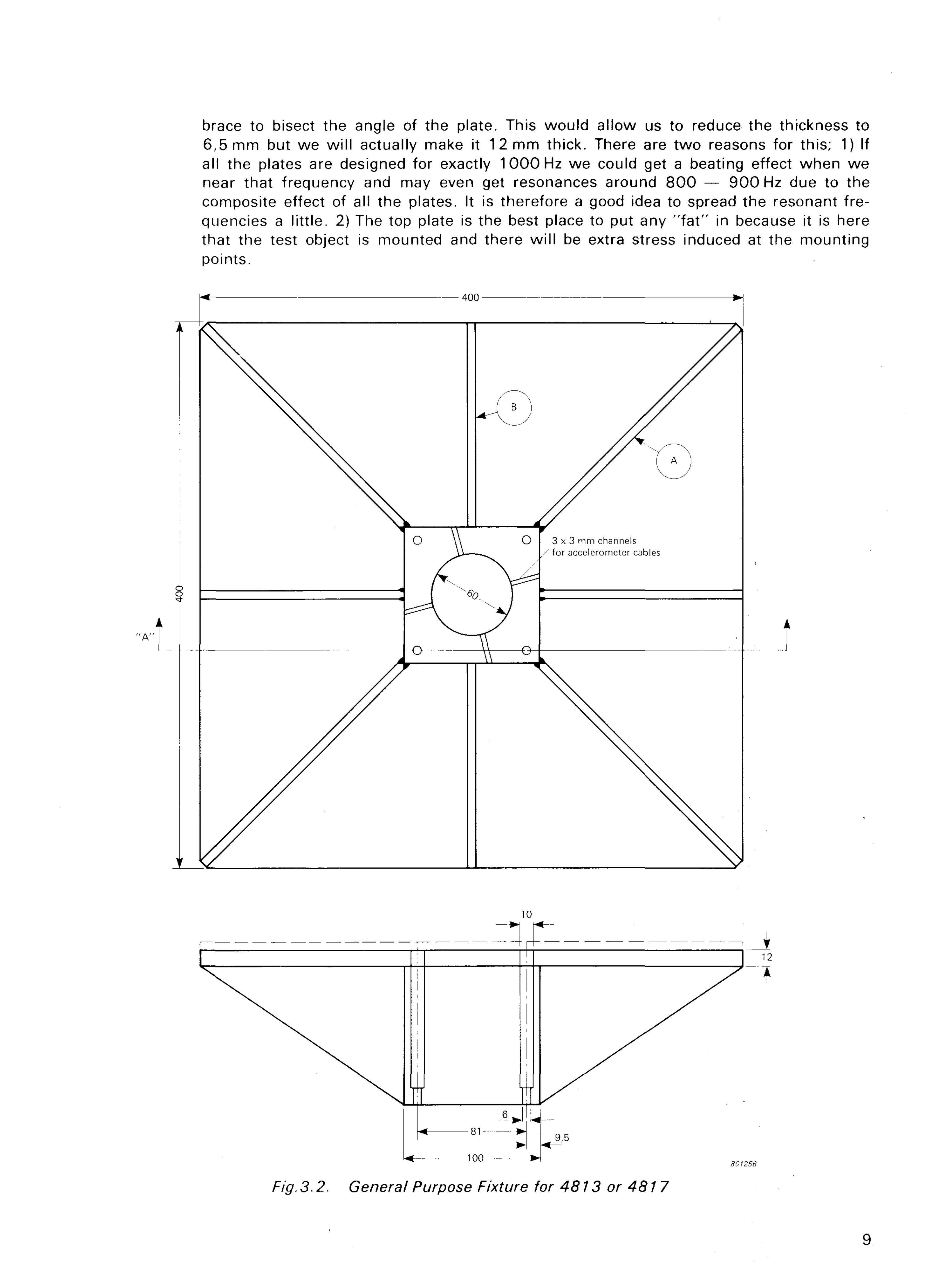
brace to bisect the angle of the plate. This would allow us to reduce the thickness to 6,5 mm but we wi l l actually make it 12 mm thick. There are two reasons for this; 1) If all the plates are designed for exactly 1000 Hz we could get a beating effect when we near that frequency and may even get resonances around 8 0 0 — 9 0 0 Hz due to the composite effect of all the plates. It is therefore a good idea to spread the resonant frequencies a litt le. 2) The top plate is the best place to put any " f a t " in because it is here that the test object is mounted and there wi l l be extra stress induced at the mounting points.
Fig. 3.2. General Purpose Fixture for 4813 or 4817
9
The fixture now looks like that shown in Fig.3.2. The resonant frequency of the top plate can be calculated using eq. (1) and the relation given in Fig.2.4.
1 2 f 4 x 23,5 x 104 x '—- x 1,31 = 1845 Hz
28,32
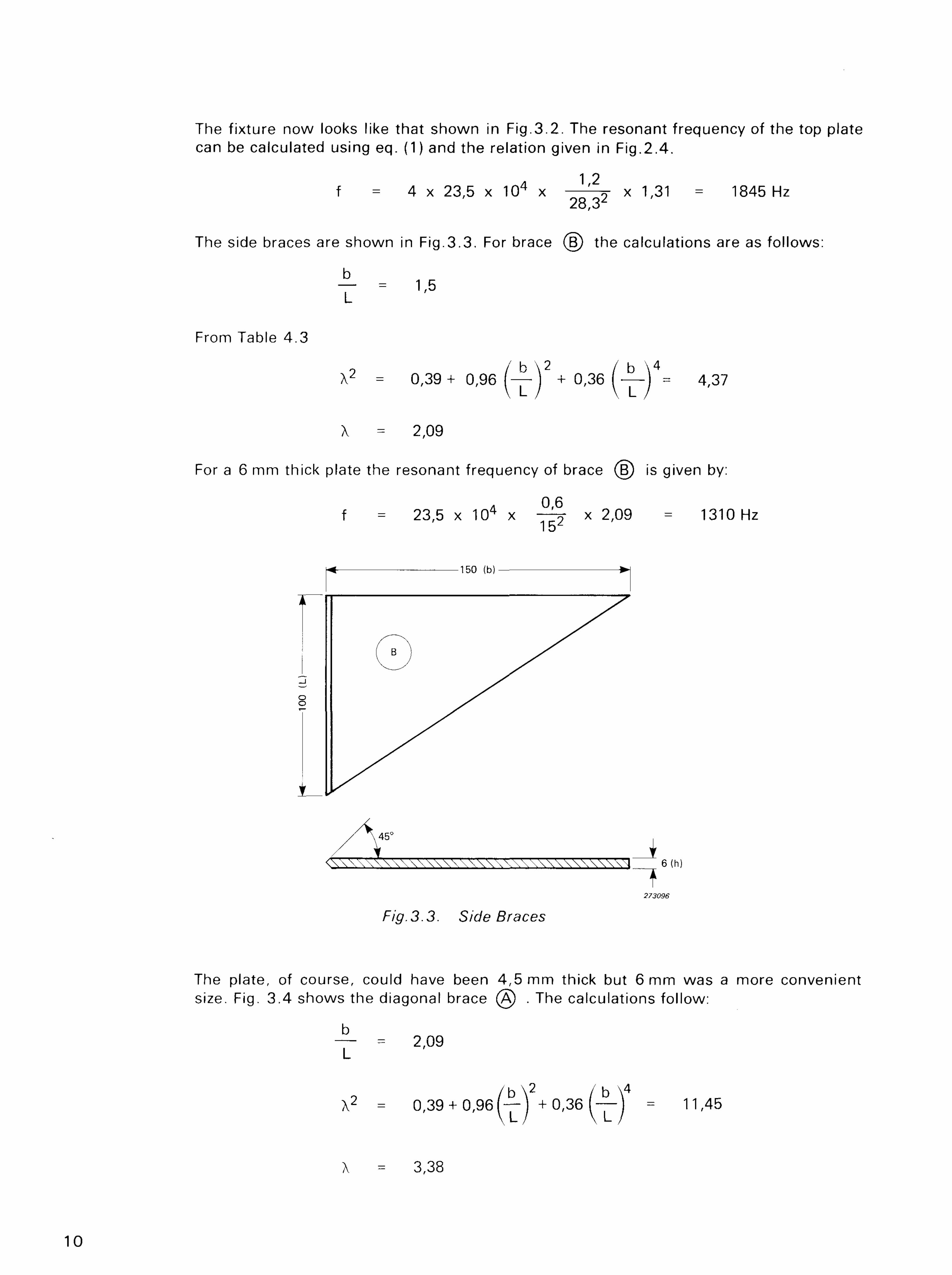
The side braces are shown in Fig.3.3. For brace (§) the calculations are as follows:
b T = 1'6
From Table 4.3
X2 = 0,39+ 0,96 ( — ) + 0,36 (—) - 4,37
X = 2,09
For a 6 mm thick plate the resonant frequency of brace (§) is given by:
A 0,6 f = 23,5 x 10⁴ x — ^ * 2,09 = 1310 Hz
Fig. 3.3. Side Braces
The plate, of course, could have been 4,5 mm thick but 6 mm was a more convenient size. Fig. 3.4 shows the diagonal brace (A) . The calculations follow:
b — - 2,09
L
X2 = 0,39 + 0 ,96(—) + 0,36 \—\ = 11,45
X = 3,38
10
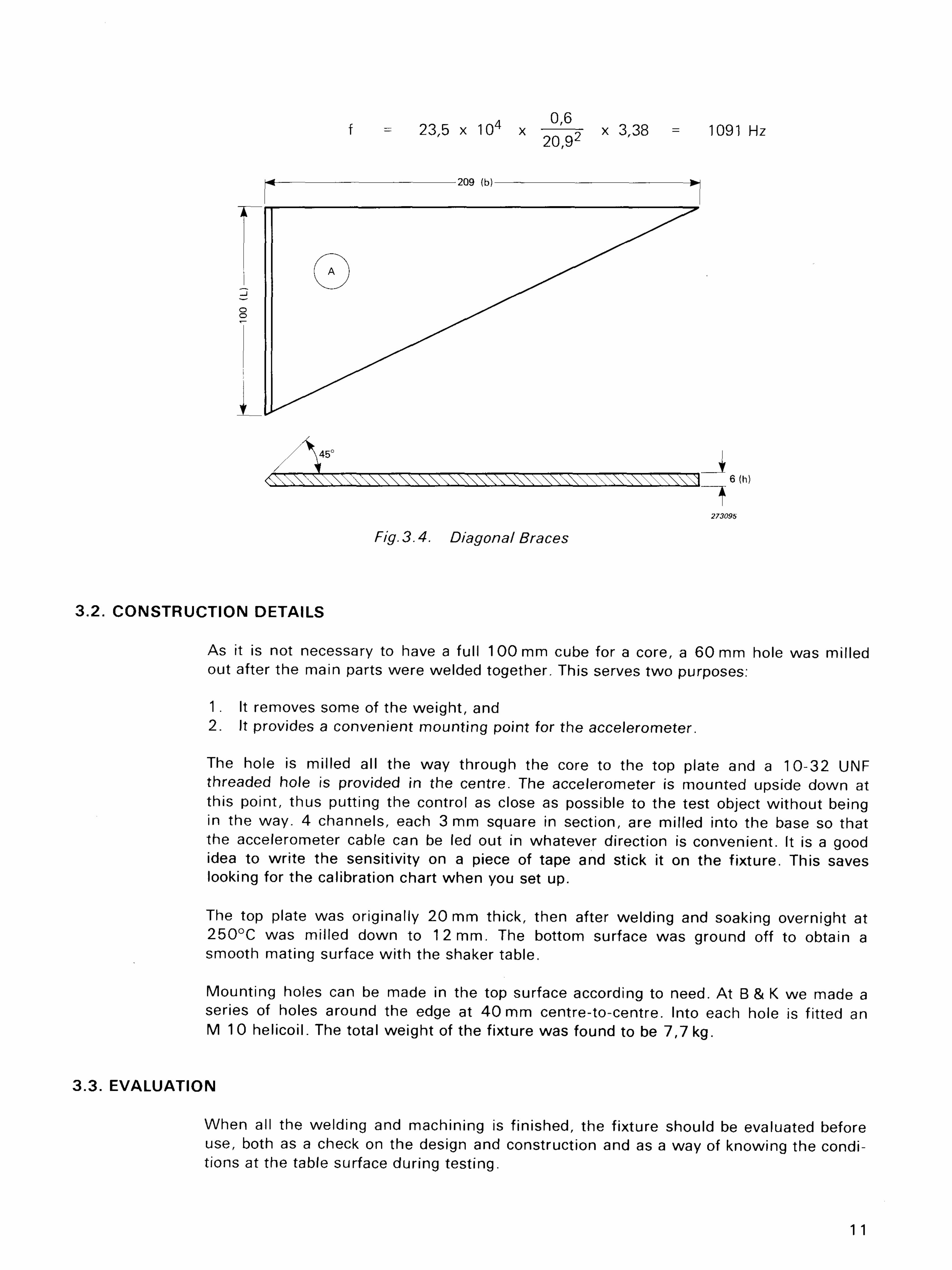
Fig. 3.4. Diagonal Braces
A 0,6 f = 23,5 x 10⁴ x —~ x 3,38 = 1091 Hz
20,92
3.2. CONSTRUCTION DETAILS
As it is not necessary to have a full 100 mm cube for a core, a 60 mm hole was milled out after the main parts were welded together. This serves two purposes:
1 . It removes some of the weight, and 2. It provides a convenient mounting point for the accelerometer.
The hole is milled all the way through the core to the top plate and a 10-32 UNF threaded hole is provided in the centre. The accelerometer is mounted upside down at this point, thus putting the control as close as possible to the test object wi thout being in the way. 4 channels, each 3 mm square in section, are milled into the base so that the accelerometer cable can be led out in whatever direction is convenient. It is a good idea to wri te the sensitivity on a piece of tape and stick it on the f ixture. This saves looking for the calibration chart when you set up.
The top plate was originally 20 mm thick, then after welding and soaking overnight at 250°C was milled down to 12 mm. The bottom surface was ground off to obtain a smooth mating surface wi th the shaker table.
Mounting holes can be made in the top surface according to need. At B & K we made a series of holes around the edge at 4 0 mm centre-to-centre. Into each hole is fitted an M 1 0 helicoil. The total weight of the fixture was found to be 7,7 kg.
3 .3 . EVALUATION
When all the welding and machining is f inished, the fixture should be evaluated before use, both as a check on the design and construction and as a way of knowing the conditions at the table surface during testing.
1 1
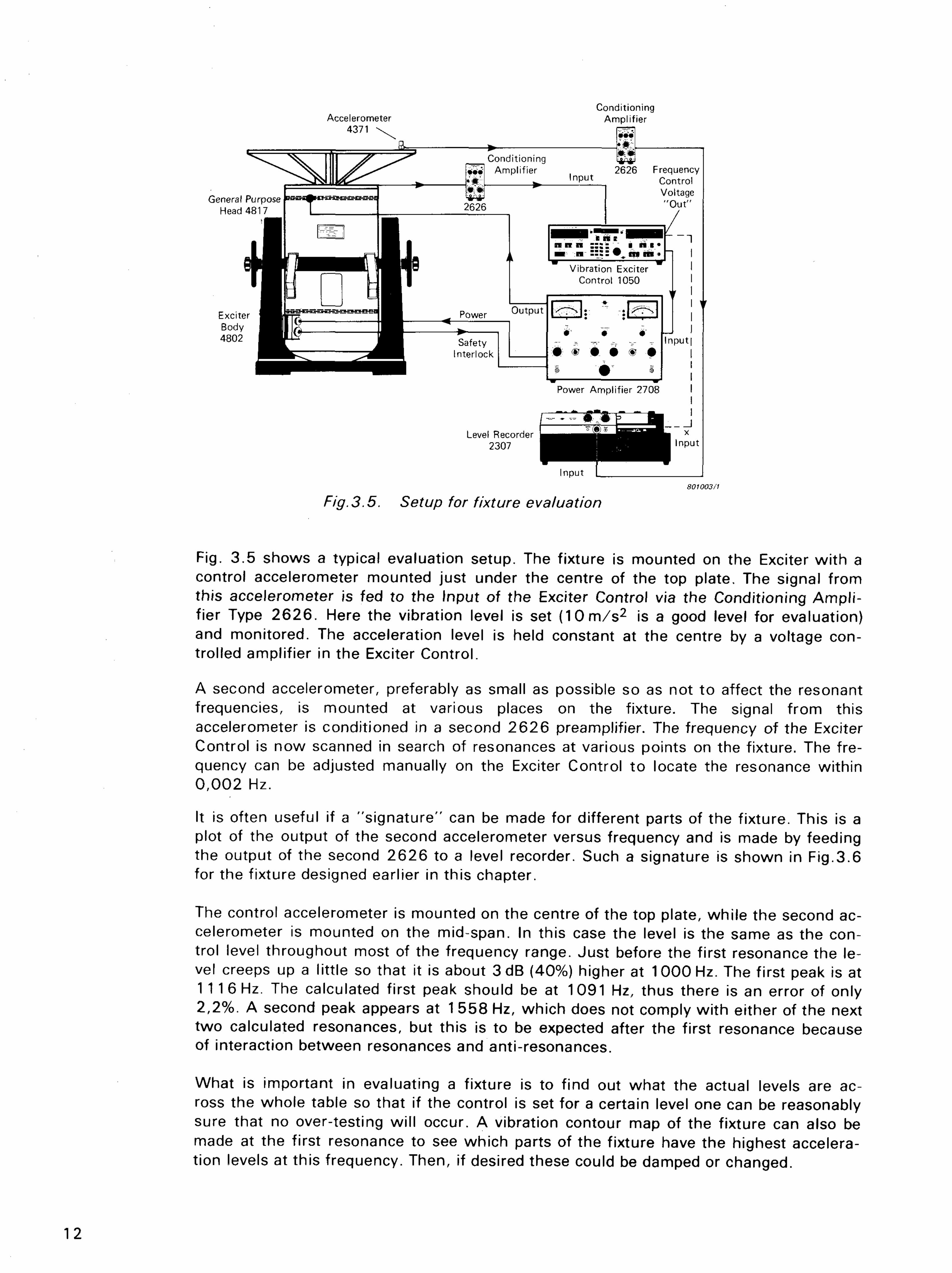
Fig. 3.5. Setup for fixture evaluation
Fig. 3.5 shows a typical evaluation setup. The fixture is mounted on the Exciter wi th a control accelerometer mounted just under the centre of the top plate. The signal from this accelerometer is fed to the Input of the Exciter Control via the Conditioning Ampl ifier Type 2626 . Here the vibration level is set ( 1 0 m / s 2 is a good level for evaluation) and monitored. The acceleration level is held constant at the centre by a voltage controlled amplifier in the Exciter Control.
A second accelerometer, preferably as small as possible so as not to affect the resonant frequencies, is mounted at various places on the fixture. The signal from this accelerometer is conditioned in a second 2 6 2 6 preamplifier. The frequency of the Exciter Control is now scanned in search of resonances at various points on the fixture. The frequency can be adjusted manually on the Exciter Control to locate the resonance within 0 ,002 Hz.
r
It is often useful if a "signature" can be made for different parts of the fixture. This is a plot of the output of the second accelerometer versus frequency and is made by feeding the output of the second 2626 to a level recorder. Such a signature is shown in Fig.3.6 for the fixture designed earlier in this chapter.
The control accelerometer is mounted on the centre of the top plate, while the second accelerometer is mounted on the mid-span. In this case the level is the same as the control level throughout most of the frequency range. Just before the first resonance the level creeps up a little so that it is about 3dB (40%) higher at 1000 Hz. The first peak is at 1 1 1 6 Hz. The calculated first peak should be at 1091 Hz, thus there is an error of only 2,2%. A second peak appears at 1 558 Hz, which does not comply with either of the next two calculated resonances, but this is to be expected after the first resonance because of interaction between resonances and anti-resonances.
What is important in evaluating a fixture is to find out what the actual levels are across the whole table so that if the control is set for a certain level one can be reasonably sure that no over-testing wil l occur. A vibration contour map of the fixture can also be made at the first resonance to see which parts of the fixture have the highest acceleration levels at this frequency. Then, if desired these could be damped or changed.
12
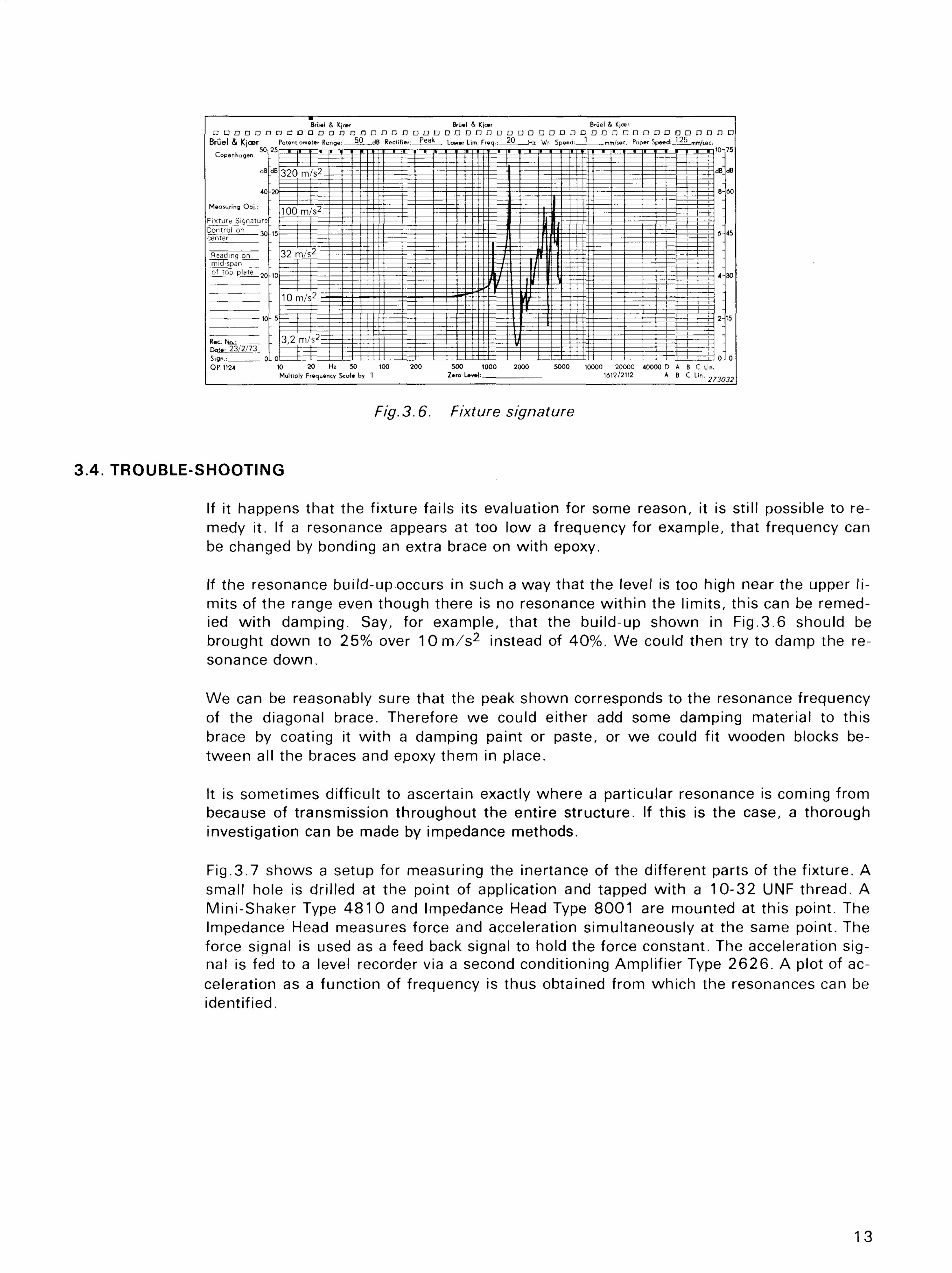
Fig. 3.6. Fixture signature
3.4. TROUBLE-SHOOTING
If it happens that the fixture fails its evaluation for some reason, it is still possible to remedy it. If a resonance appears at too low a frequency for example, that frequency can be changed by bonding an extra brace on wi th epoxy.
If the resonance build-up occurs in such a way that the level is too high near the upper l i mits of the range even though there is no resonance wi th in the l imits, this can be remedied wi th damping. Say, for example, that the build-up shown in Fig.3.6 should be brought down to 25% over 1 0 m / s 2 instead of 40%. We could then try to damp the resonance down.
We can be reasonably sure that the peak shown corresponds to the resonance frequency of the diagonal brace. Therefore we could either add some damping material to this brace by coating it wi th a damping paint or paste, or we could fit wooden blocks between all the braces and epoxy them in place.
It is sometimes difficult to ascertain exactly where a particular resonance is coming from because of transmission throughout the entire structure. If this is the case, a thorough investigation can be made by impedance methods.
Fig.3.7 shows a setup for measuring the inertance of the different parts of the f ixture. A small hole is drilled at the point of application and tapped wi th a 10-32 UNF thread. A Mini-Shaker Type 4 8 1 0 and Impedance Head Type 8001 are mounted at this point. The Impedance Head measures force and acceleration simultaneously at the same point. The force signal is used as a feed back signal to hold the force constant. The acceleration sig-nal is fed to a level recorder via a second conditioning Amplif ier Type 2 6 2 6 . A plot of acceleration as a function of frequency is thus obtained from which the resonances can be identified.
13
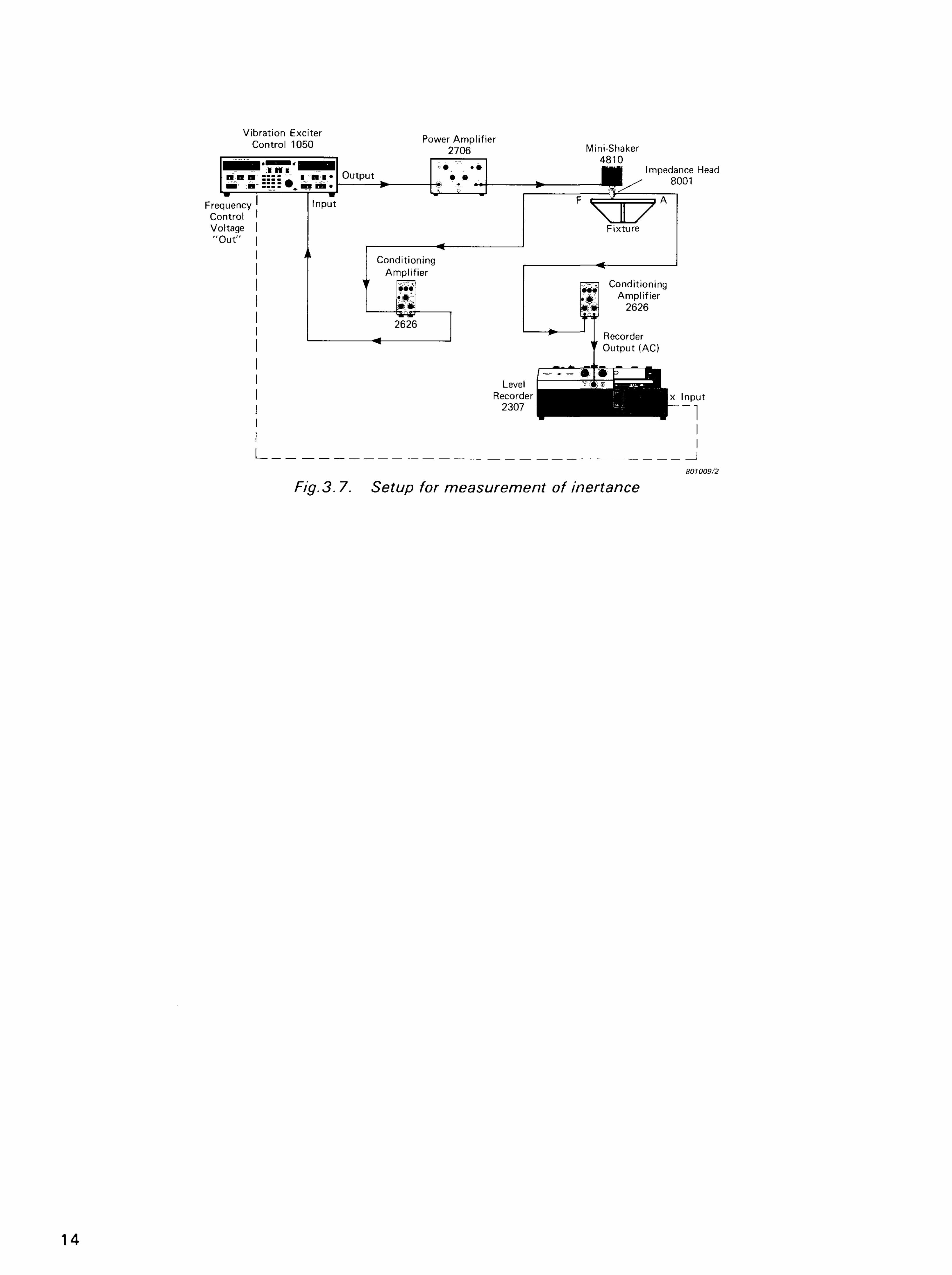
Fig.3.7. Setup for measurement of inertance
14
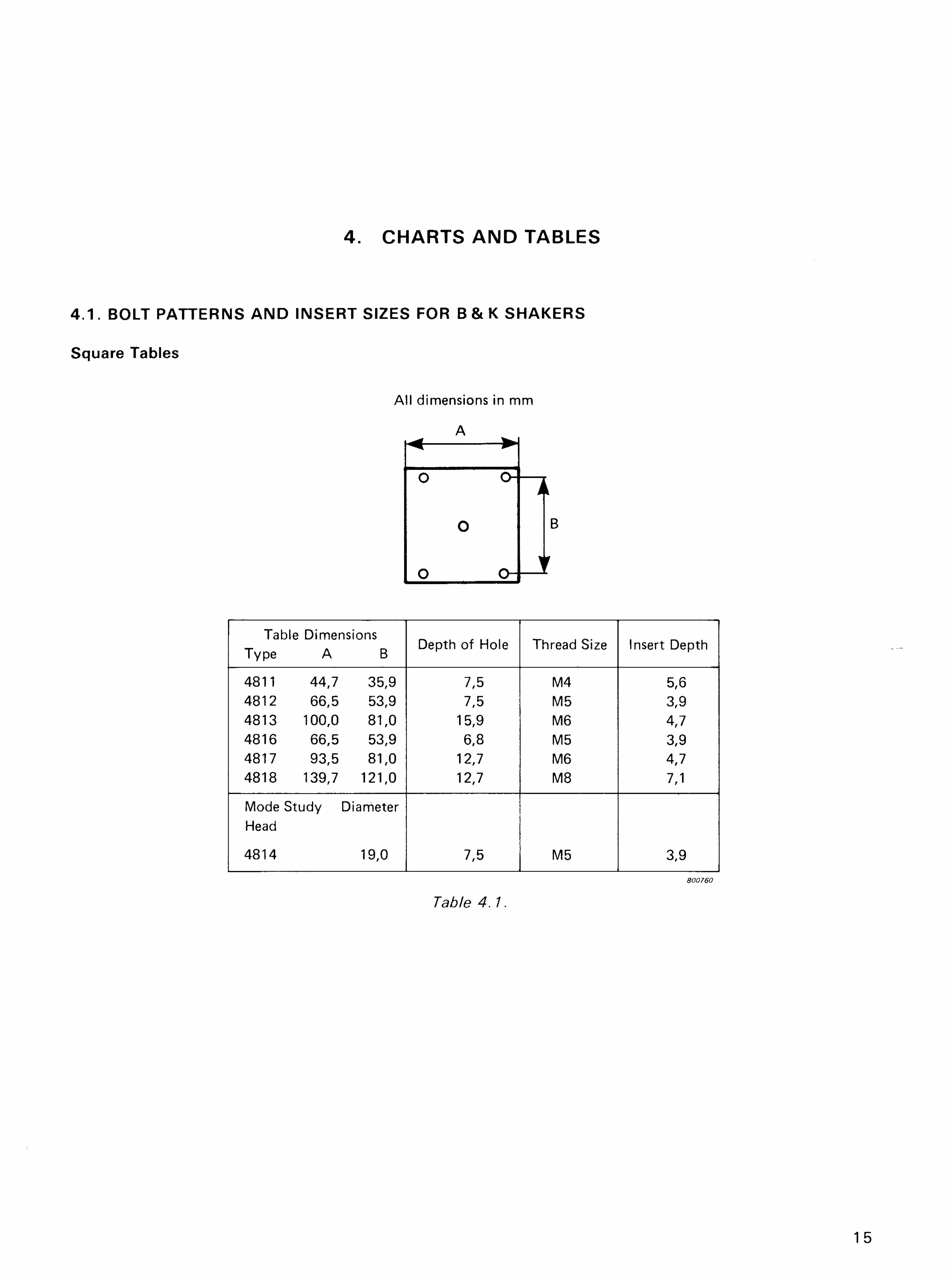
Table Dimensions Type A B
Depth of Hole Thread Size Insert Depth
4811 44,7 35,9 7,5 M4 5,6 4812 66,5 53,9 7,5 M5 3,9 4813 100,0 81,0 15,9 M6 4,7 4816 66,5 53,9 6,8 M5 3,9 4817 93,5 81,0 12,7 M6 4,7 4818 139,7 121,0 12,7 M8 7,1
Mode Study Diameter Head
4814 19,0 7,5 M5 3,9 800760
Table 4. 1.
15
4. CHARTS AND TABLES
4 . 1 . BOLT PATTERNS AND INSERT SIZES FOR B & K SHAKERS
Square Tables
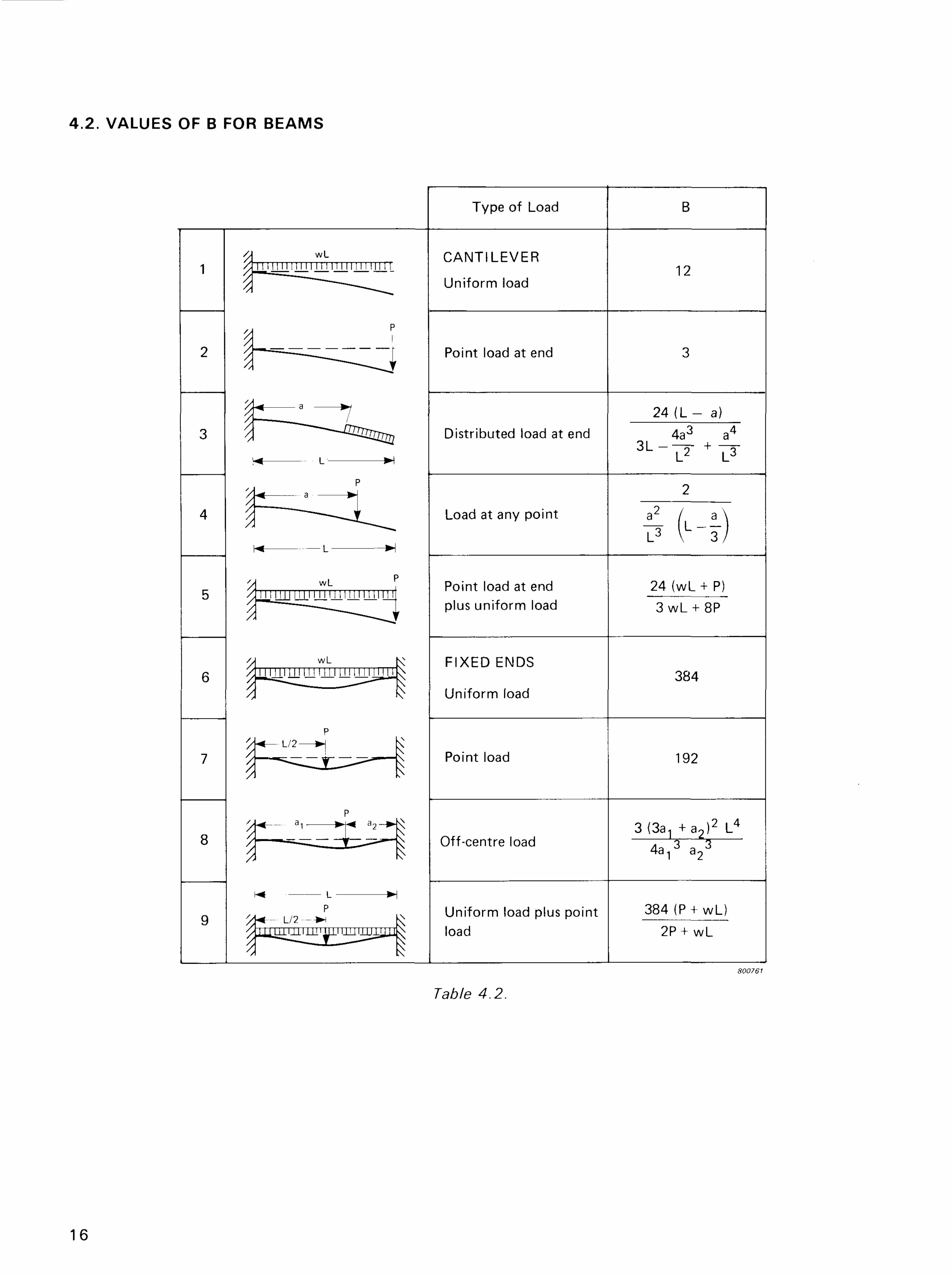
4.2. VALUES OF B FOR BEAMS
Type of Load B
CANTILEVER
Uniform load 12
Point load at end 3
Distributed load at end 24 ( L - a)
Distributed load at end 4a3 a4
3 L " L 2 + L 3
Load at any point
2
Load at any point
F (-1)
Point load at end plus uniform load
24 (wL+ P) 3 wL + 8P
FIXED ENDS
Uniform load 384
Point load 192
Off-centre load 3 ^ + a 2 ) 2 L4
4 8 ^ a 23
Uniform load plus point load
384 (P + wL) 2P + wL
Table 4.2.
800761
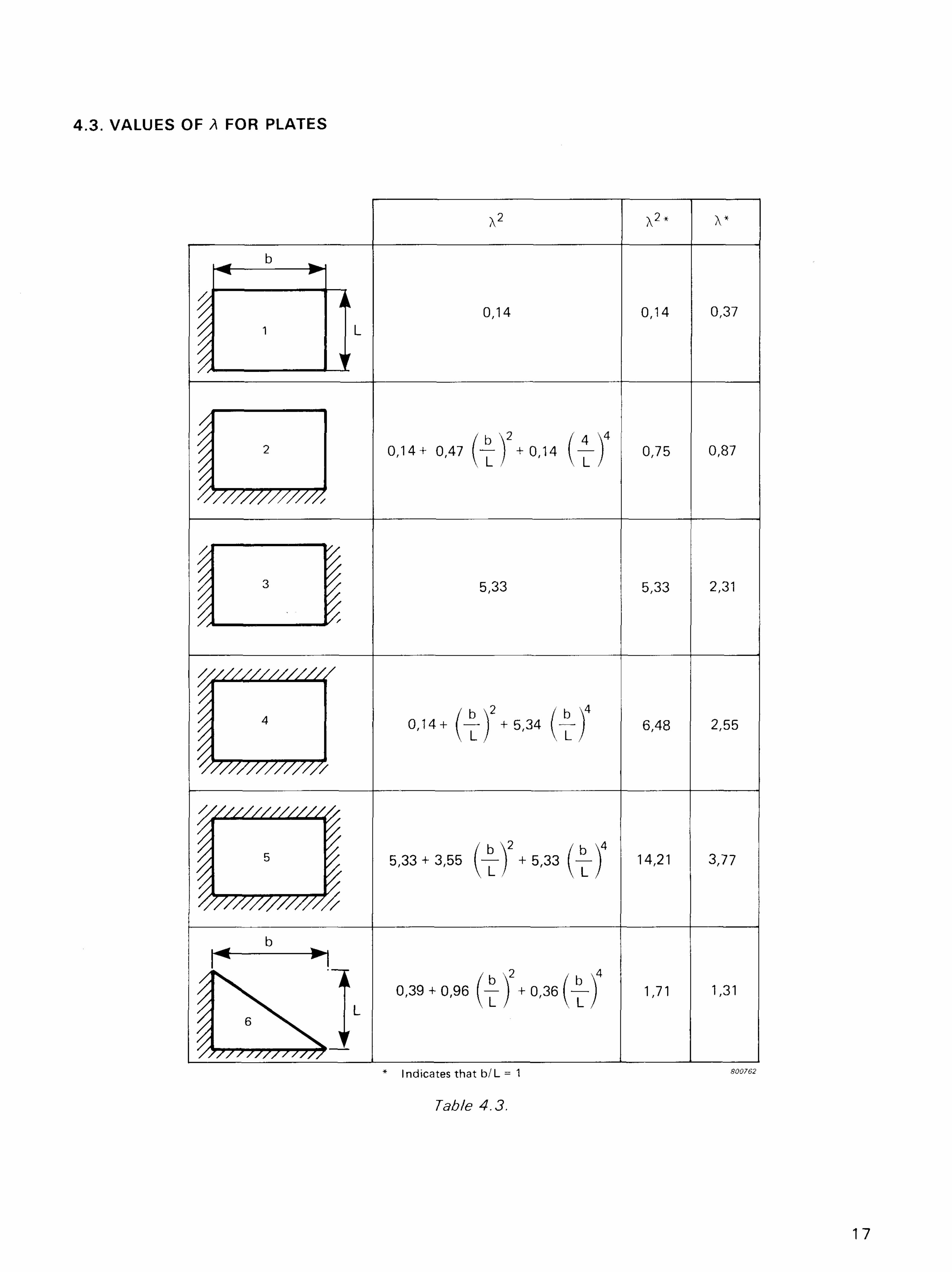
4 .3 . VALUES OF A FOR PLATES
X2 X2* x*
0,14 0,14 0,37
0,14+ 0,47 f — j +0,14 ( — j 0,75 0,87
5,33 5,33 2,31
0,14+ ( — j +5,34 I —\ 6,48 2,55
5,33 + 3,55 (—) + 5,33 (—) 14>21 3,77
0,39 + 0,96 (—) + 0 , 3 6 ( — ] 1,71 1,31
I ^ — _ ^ — - ^ 1 1
* Indicates that b / L = 1 800762
Table 4.3.
17
LU >
-Q LL O
O
m
18
z o <
a LU UJ H <
Q_
cc O LL X a. <
cc
O
O z
19
5. BIBLIOGRAPHY OF TEST FIXTURE LITERATURE
1. "Vibration and Shock Test Fixture Design", Tustin Institute of Technology, Santa Barbara, California, USA, 1 9 7 1 .
2. "The Vibration of Rectangular Plates", G.B. Warburton, Proc, of Inst. of M.E., 1953 .
3. "Lectures on Shock and Vibrat ion", Robert L. Stallard, Avco Corporation, Wi lmington, Mass., USA, given March-June 1967 at Northeastern University.
4 . "Vibration of Plates", A.W. Leissa, NASA Publication SP-1 60 .
5. Handbook of Shock and Vibration, edited by Harris and Crede, McGraw-Hi l l .
6. Mechanical Design and Systems Handbook, Harold A. Rothbart, Editor, McGraw-Hil l .
7. "Estimating Natural Frequencies", H.W. Schmitt, Machine Design magazine, Dec. 9, 1965.
8. "Speed of Sound Limits Size of Vibrating Structure", Wayne Tustin, Test Engineering and Management, Sept. 1966 .
9. "Bui l t - in Damping", R.P. Thorn, Machine Design, Nov. 25 and Dec. 9, 1 965 .
10. "Impedance Simulation Vibration Test Fixtures for Spacecraft Tests", Terry D. Schar-ton. Bolt Beranek and Newman Inc. Van Nuys, California, USA*
1 1. "Vibration of Sandwich Panels in a Vacuum" , Clemans A. Powell, Jr. and David G. Stephens, NASA Langley Research Center, in Shock and Vibration Bullet in, No. 38 .
12. "Formulas for Natural Frequency and Mode Shape", Robert D. Blevins. Van Nos-trand Reinhold Company.
There is also a wealth of information available from:
Shock and Vibration Information Center Code 6 0 2 0 , Naval Research Laboratory Washington, D.C. 2 0 3 9 0 USA
Quite often an article in their publication, "Shock and Vibration Bul let in" , wi l l have information on the f ixturing for a test even though the test itself is the main theme of the article.
20