Embed Size (px)
Citation preview

13th World Conference on Earthquake Engineering Vancouver, B.C., Canada
August 1-6, 2004 Paper No. 153
VIBRATION TESTS OF ACTUAL BUILDINGS WITH SEMI-ACTIVE SWITCHING OIL DAMPER
Kan SHIMIZU1, Toshikazu YAMADA2, Jun TAGAMI3 and Haruhiko KURINO4
SUMMARY The semi-active oil damper described in this paper switches its damping coefficient from maximum to minimum and dissipates twice as much energy as an ordinary passive damper. Its performance has already been verified under dynamic loading tests with a full-scale device and a forced vibration test on a mid-rise building, which was the first building with this semi-active oil damper. In order to verify the performance of this semi-active oil damper under low frequency and small vibration, a forced vibration test was conducted on a high-rise building with a first natural period of over 4sec. The results showed that the damper works from a very small stroke of about 0.1mm and adds 1.6 times the damping ratio of an ordinary passive damper. This building also has a wind and earthquake observation system, and the effectiveness of the damper against small earthquakes has also verified from the records.
INTRODUCTION Recently, various energy dissipation devices have been researched and developed to reduce the structural response due to earthquakes or wind forces. The semi-active oil damper presented in this paper maximizes the energy dissipation capacity under the mechanical constraint associated with a Maxwell model by switching its damping coefficient to the maximum or the minimum, Kurino [1]. It dissipates twice as much energy as an ordinary passive damper. Its improved energy dissipation capacity has already been verified by dynamic loading tests on a full-scale device under various conditions including random excitations. Another remarkable feature of the device verified from the tests is that it begins to perform its control function at a very small stroke. This feature enables it to reduce structural responses due to wind forces as well as earthquakes. This damper was first applied to a mid-rise building in Gifu, Japan, Mori [2]. Forced vibration tests were conducted on this building and the effect of the damper was verified in an actual building, Tagami [3]. Now, hundreds of devices have been applied to more than ten high-rise buildings in Japan. In a high-rise building, wind vibrations become more significant than in a mid-rise building. The wind vibrations of high-rise building are very small amplitude with low frequency. This is a hard condition for a damper installed in the inter-story of the building. Therefore, in order to verify the 1 Research Engineer, Kajima Corporation, Tokyo, Japan. Email: [email protected] 2 Deputy Director, Kajima Corporation, Tokyo, Japan. 3 Supervisory Research Engineer, Kajima Corporation, Tokyo, Japan. 4 Principal Research Engineer, Kajima Corporation, Tokyo, Japan.

performance of the damper under low frequency and small vibration, forced vibration tests were conducted on a high-rise building whose first natural period is over 4sec. This building is 170m high and equipped with 88 dampers and also has a wind and earthquake observation system. Several earthquake records were observed in 2003. In this paper, the results of the forced vibration tests conducted on this high-rise building and the result of the observed earthquake records are reported, and their control effects are discussed.
OUTLINE OF THE SEMI-ACTIVE OIL DAMPER Figure 1 describes the inner mechanism and the force-velocity relations of the semi-active oil damper. The damper has three different valves. V1 is the main control valve, which switches its damping coefficient to Cmax or Cmin according to the opening signal from a built-in controller. V2 is a relief valve, which keeps the damper force within the design load to protect the device. V3 is, so to speak, a failsafe valve. When the power supply is cut off, V1 closes and V3 opens mechanically, and the device changes to an orifice-type passive damper with Cp in Figure 1(b).
Figure 1. Inner mechanism and force-velocity relations of semi-active oil damper A mechanical model of the damper installed in the building with a brace is shown in Figure 2. The model is expressed as a Maxwell model that changes its damping coefficient. The control algorithm that realizes maximum energy dissipation under Maxwell model’s constraint, shown in Kurino [1], is:
⎩⎨⎧
=><×<×=≤≥×≥×
min0
max0
)(:00)(:00
CtCFFanduFandxF
CtCFForuForxF&
& (1)
where F is damper force, F0 is the minimum force that the damper operates, x& is the velocity of the story in which the damper is installed and u is the filtered x& . Figure 3 shows the force-displacement loop of the damper portion. The damping coefficient is normally kept at Cmax and switched to Cmin when the story velocity changes direction. As a result of this control law, twice as much energy as an ordinary passive damper can be dissipated, as shown in Figure 3(a). The filtered velocity u has the role of avoiding excessive frequent unloading due to the higher-mode’s component mixed in the inter-story velocity of the
(a) Inner mechanism (b) Force-velocity relations
FR FM
Dashpot velocity
Cmax
Cmin
Cp
F
-FR -FM
Cmax : V1,V2,V3:Close Cp : V1,V2:Close,V3:Open Cmin : V1:Open,V2,V3:Close Joint part Body Joint part
V1
V2 V3
V1:Control valve V2:Relief valve V3:Failsafe valve
Stroke Dp Controller
Opening signal Accumulator
Oil
Power supply
P1 P2 Pressure

Multi Degree of Freedom (MDOF) structure under random disturbances, as shown in Figure 3(b). Because all the information required for control can be obtained from the sensors built into the device, it is possible to realize a closed control circuit in each device by also attaching the controller to each device. This integrated control device, or decentralized autonomous control system, has robustness against some machine trouble, and it makes the installation in the structure as easy as for an ordinary passive damper.
Figure 2. Mechanical model of damper
Figure 3. Relations between damper force and inter-story displacement
OUTLINE OF HIGH-RISE BUILDING The building presented here is the Shiodome Tower, 170m high, located in Tokyo, Japan. An outside view is shown in Figure 4(a). Figures 4(b) to 4(d) describe the plan and the section of the building. It is used as a hotel and an office. In order to reduce the building’s response against earthquakes and winds, 88 semi-active oil dampers were installed from the 2nd to the 23rd floors in the transverse direction. Figure 5 shows one of the dampers installed in the building, and its specifications are shown in Table 1. When two dampers were set on both sides of the brace as in Figure 5, the sensors are set to only one damper so that the timing of the valve opening of both dampers becomes similar. From the results of the wind tunnel tests, the building was expected to suffer from strong winds. To make the hotel comfortable against these winds, two Active Passive Composite Tuned Mass Dampers (APTMD) shown in Ohrui [4] that work in both directions are also set on the roof floor. The mass of the Active Mass Damper (AMD) is 10ton and that of the Tuned Mass Damper (TMD) is 30ton. The stroke of the AMD is 93cm and that of the TMD is 46cm. These APTMD are used as excitors during forced vibration tests.
Column
Damper
Beam
Brace
x
k C (t)
F
x
Target orbit by filtered velocity
x&Excessive frequent
unloading judgment by x&
(b) Random disturbance
x δ
−δ k
−2kδ
F
Cmin
Semi-actively controlled
Passive damper
2kδ
Cmax
Cmax
Cmin
(a) Stationary condition

Figure 4 Shiodome Tower
Figure 5. Semi-active oil damper installed in the building
Table 1. Specifications Item Specification
Maximum design force FM 1,500kN Relief force FR 1,300kN
Maximum piston stroke 120mm Stiffness kd 500MN/m
Size φ370×1435mm Power consumption Approximately 50W
Controller Control Command
Damper (with Sensor) Signal (Sensor)
Damper (without Sensor)
(a) Outside view
N
Hot
el
Offi
ce
27.0
m
67.2m
Semi-active Oil Damper
APTMD
(b) Plan (Roof Floor)
(c) Plan (Office) (d) Section
Dire
ctio
n of
the
Tes
t

FORCED VIBRATION TEST Description The test cases are shown in Table 2. The direction of the tests was transverse direction in which the oil damper is installed. In order to verify the control effectiveness of the semi-active oil damper, stationary excitation and free vibration tests were conducted in the three different damper states, “Controlled”, “Uncontrolled passive”, and “Uncontrolled lock”. In “Uncontrolled lock”, the damping coefficient of the damper is kept at Cmax. This is not a normal state, but it is used to estimate the fundamental characteristic of the building. In “Uncontrolled passive”, the damper becomes a passive damper with Cp shown in Figure 1(b). In order to verify the amplitude dependency of the damper, the excitation force of the “Controlled” case is set to 25, 50, and 70kN. The excitation force of the “Uncontrolled” cases is set to 25kN, so that the response amplitude of the roof floor becomes similar to that of the “Controlled” case.
Table 2. Test cases Name State of Oil Damper Excitation Level Type
LS Uncontrolled Lock Stationary LF (Cmax)
25kN Free Vibration
PS Uncontrolled Passive Stationary PF (Cp)
25kN Free Vibration
CS Controlled 25,50,70kN Stationary CF (Cmax or Cmin) 70kN Free Vibration
Results Stationary excitation test Figure 6 shows the normalized resonance curves of the each damper state. The similar resonance curves that are the results of the mid-rise building are shown in Tagami [3]. In “Uncontrolled passive”, because the generated damper force is negligible, as shown in Figure 7(a), its resonant frequency, 0.233Hz, is considered as the natural frequency without a damper. In “Uncontrolled lock” the resonant frequency is estimated 0.239Hz. It becomes high because the damper behaves as a spring and dissipates little energy, as shown in Figure 7(a). For “Controlled” it is between “Uncontrolled passive” and “Uncontrolled lock”. The peak of the resonance curve for “Controlled” is reduced by about two third. Figure 7(b) shows the force-stroke relation of “Controlled”. The damper begins to work at a very small stroke of about 0.1mm and shows a parallelogram shape, which is typical for this control theory. The shape was similar at each force level. Figure 8 shows the normalized time histories at the peak of each resonance curve. In spite of the application of the nonlinear control theory, the acceleration time history of “Controlled” is also stable.
Figure 6. Resonance curve of the roof floor
0.2 0.22 0.24 0.26 0.28Frequency(Hz)
0
0.5
1
1.5
2
Nor
mal
ized
Vel
ocity
(cm
/s/1
0kN
)
Uncontrolled Lock (LS) 0.239Hz(4.18s)
Uncontrolled Passive(PS) 0.233Hz(4.29s)
Controlled(CS:70kN) 0.236Hz(4.24s)

Figure 7. Force-displacement relations of oil damper
20 40 60 80 100
(sec)-4
0
4
Nor
mal
ized
acc
(cm
/s2 /
10kN
)
(a)Uncontrolled Lock(LS:0.239Hz)
20 40 60 80 100
(sec)-4
0
4
Nor
mal
ized
acc
(cm
/s2 /
10kN
)
(b)Uncontrolled Passive(PS:0.233Hz)
20 40 60 80 100
(sec)-4
0
4
Nor
mal
ized
acc
(cm
/s2 /
10kN
)
(c)Controlled(CS:70kN:0.236Hz)
Figure 8. Time history of roof floor acceleration
Free vibration test In order to estimate the damping ratio of each damper state, free vibration tests were conducted. Figure 9 shows the time history of the roof floor. The identified damping ratio of each cycle is shown in Figure 10. The identified damping ratios of the uncontrolled cases are constant and their results are 1.1% for “Uncontrolled passive” and 0.9% for “Uncontrolled lock”. However, for “Controlled” the identified damping ratio reaches 3% when the amplitude of the roof floor is 2cm/s. The stroke of the damper is only about 0.15mm at this amplitude. In ‘Uncontrolled lock’ the damper acts as a spring. Therefore, the damping ratio of a building without a damper is estimated at 0.9%. From these results, the added damping ratio of “Controlled” is estimated at 2.1%.
(b)Controlled
-0.4 0 0.4Stroke(mm)
-100
0
100
For
ce(k
N)
Controlled(CS:70kN:0.236Hz)
Controlled(CS:50kN:0.236Hz)
Controlled(CS:25kN:0.236Hz)
(a)Uncontrolled
-0.4 0 0.4Stroke(mm)
-100
0
100
For
ce(k
N)
Uncontrolled Passive (PS:0.233Hz)
Uncontrolled Lock(LS:0.239Hz)

40 80 120-3
0
3
Vel
ocity
(RF
)(c
m/s
)
(a) Uncontrolled Lock (LF)
40 80 120-3
0
3
Vel
ocity
(RF
)(c
m/s
)
(sec) (b) Uncontrolled Passive (PF)
40 80 120-3
0
3
Vel
ocity
(RF
)(c
m/s
)
(c) Controlled (CF)
Figure 9. Time history of the roof floor velocity
0 1 2 3RF Peak Velocity (cm/s)
0.00
0.01
0.02
0.03
0.04
Dam
ping
Fac
tor
h=1.1%h=0.9%
h=3.0%
Controlled (CF)
Uncontrolled Passive (PF)
Uncontrolled Lock (LF)
Figure 10. Evaluated damping ratio
Comparison between semi-active oil damper and passive oil damper From the results of the free vibration tests, the added damping ratio for “Controlled” is estimated at 2.1%. However, because of the characteristic of the orifice type passive damper under small vibration, the added damping ratio of “Uncontrolled passive” is expected to be less than that of “Optimized passive”, whose damping coefficient is optimized. In order to estimate the added damping ratio by the “Optimized passive” theoretically, a 4-element vibration model is introduced, as shown in Figure 11.
Figure 11. 4-element vibration model
M
Cd
Kd Kf Cf
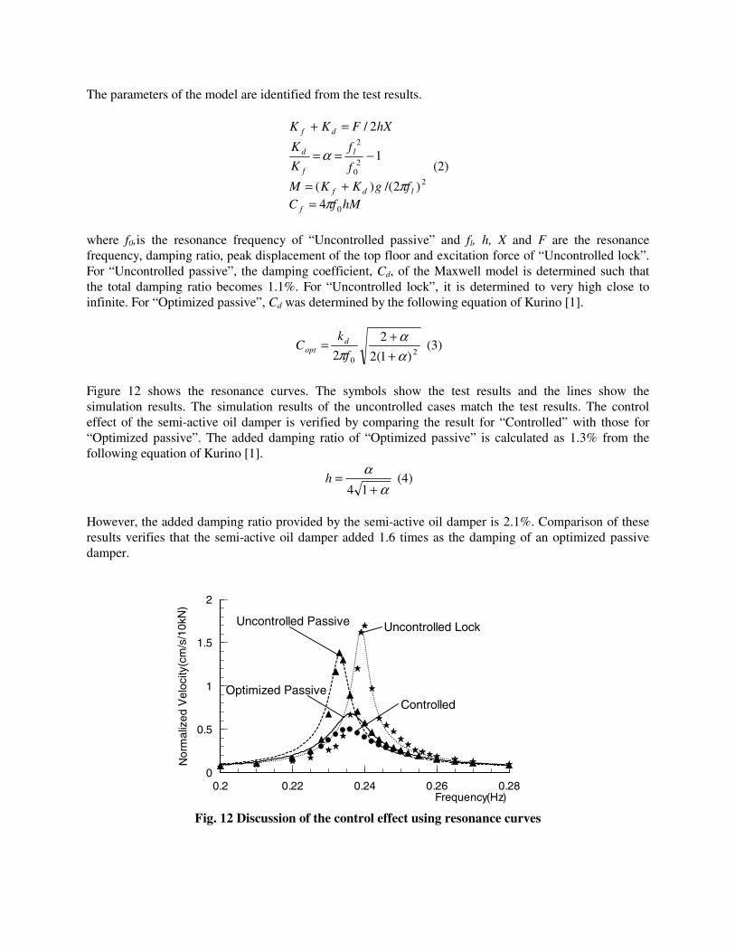
The parameters of the model are identified from the test results.
hMfCfgKKM
f
f
K
K
hXFKK
f
ldf
l
f
d
df
0
2
20
2
4)2/()(
1
2/
ππ
α
=+=
−==
=+
(2)
where f0,is the resonance frequency of “Uncontrolled passive” and fl, h, X and F are the resonance frequency, damping ratio, peak displacement of the top floor and excitation force of “Uncontrolled lock”. For “Uncontrolled passive”, the damping coefficient, Cd, of the Maxwell model is determined such that the total damping ratio becomes 1.1%. For “Uncontrolled lock”, it is determined to very high close to infinite. For “Optimized passive”, Cd was determined by the following equation of Kurino [1].
20 )1(2
2
2 αα
π ++=
f
kC d
opt (3)
Figure 12 shows the resonance curves. The symbols show the test results and the lines show the simulation results. The simulation results of the uncontrolled cases match the test results. The control effect of the semi-active oil damper is verified by comparing the result for “Controlled” with those for “Optimized passive”. The added damping ratio of “Optimized passive” is calculated as 1.3% from the following equation of Kurino [1].
αα
+=
14h (4)
However, the added damping ratio provided by the semi-active oil damper is 2.1%. Comparison of these results verifies that the semi-active oil damper added 1.6 times as the damping of an optimized passive damper.
Fig. 12 Discussion of the control effect using resonance curves
0.2 0.22 0.24 0.26 0.28Frequency(Hz)
0
0.5
1
1.5
2
Nor
mal
ized
Vel
ocity
(cm
/s/1
0kN
)
Uncontrolled Lock Uncontrolled Passive
Controlled Optimized Passive
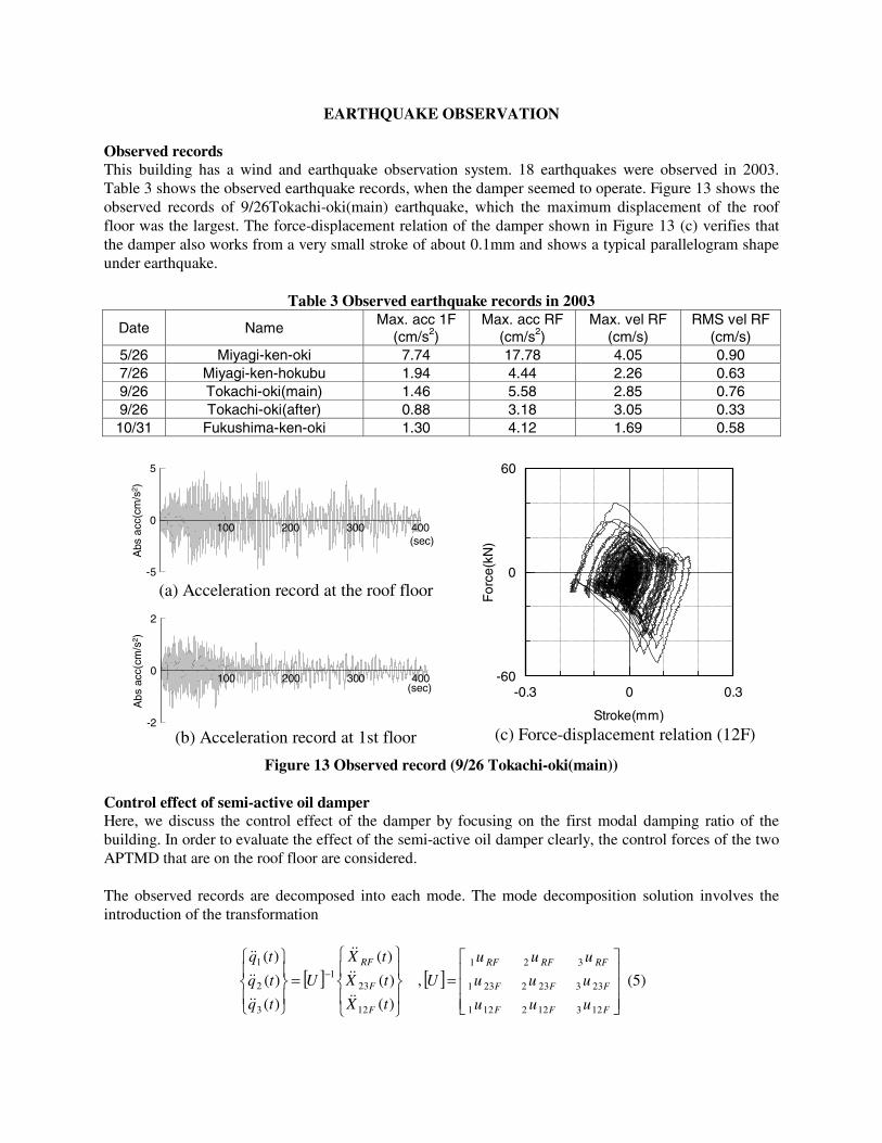
EARTHQUAKE OBSERVATION Observed records This building has a wind and earthquake observation system. 18 earthquakes were observed in 2003. Table 3 shows the observed earthquake records, when the damper seemed to operate. Figure 13 shows the observed records of 9/26Tokachi-oki(main) earthquake, which the maximum displacement of the roof floor was the largest. The force-displacement relation of the damper shown in Figure 13 (c) verifies that the damper also works from a very small stroke of about 0.1mm and shows a typical parallelogram shape under earthquake.
Table 3 Observed earthquake records in 2003
Date Name Max. acc 1F
(cm/s2) Max. acc RF
(cm/s2) Max. vel RF
(cm/s) RMS vel RF
(cm/s) 5/26 Miyagi-ken-oki 7.74 17.78 4.05 0.90 7/26 Miyagi-ken-hokubu 1.94 4.44 2.26 0.63 9/26 Tokachi-oki(main) 1.46 5.58 2.85 0.76 9/26 Tokachi-oki(after) 0.88 3.18 3.05 0.33 10/31 Fukushima-ken-oki 1.30 4.12 1.69 0.58
Figure 13 Observed record (9/26 Tokachi-oki(main))
Control effect of semi-active oil damper Here, we discuss the control effect of the damper by focusing on the first modal damping ratio of the building. In order to evaluate the effect of the semi-active oil damper clearly, the control forces of the two APTMD that are on the roof floor are considered. The observed records are decomposed into each mode. The mode decomposition solution involves the introduction of the transformation
[ ]⎪⎭
⎪⎬
⎫
⎪⎩
⎪⎨
⎧
=⎪⎭
⎪⎬
⎫
⎪⎩
⎪⎨
⎧−
)(
)(
)(
)(
)(
)(
12
231
3
2
1
tX
tX
tX
U
tq
tq
tq
F
F
RF
&&
&&
&&
&&
&&
&&
, [ ]⎥⎥⎥
⎦
⎤
⎢⎢⎢
⎣
⎡
=
FFF
FFF
RFRFRF
uuu
uuu
uuu
U
123122121
233232231
321
(5)
(a) Acceleration record at the roof floor
(b) Acceleration record at 1st floor (c) Force-displacement relation (12F)
-0.3 0 0.3
Stroke(mm)
-60
0
60
For
ce(k
N)
100 200 300 400
-2
0
2
Abs
acc
(cm
/s2 )
(sec)
100 200 300 400
-5
0
5
Abs
acc
(cm
/s2 )
(sec)

where )(tX i&& is the vector of the observed relative acceleration records, U is the matrix containing the
mode shapes of the design model, which is normalized by the participation factor, and )(tqi&& is the vector of the decomposed ith modal time history. For the 1st modal time history, a Single Degree of Freedom (SDOF) system that makes the mean-square error ε the smallest is identified. As a result, the natural period and the damping ratio are also identified. The control forces of the APTMD are considered as inputs.
dttxtq
tFM
utXtxtxhtx
T
RFF
21
0
1
11
2
))()((
)()()()(2)(
&&&&
&&
&&&
−=
+−=++
∫ε
ϖϖ (6)
where F is the total APTMD force, 1M is the 1st modal mass and T is the duration of the earthquake. The mass identified from the test, normalized by the participation factor, is used. The dotted line shows the decomposed 1st modal time history and the full line shows the identified time history of the record of 9/26Tokachi-oki(main) in Figure 14(a). These lines show a significant match. Figure 14(b) shows the identified damping ratio of each record plotted on Figure 10. The amplitude of the observed records is the Root Mean Square (RMS) of the roof floor velocity multiplied by 1.4. The results of the observed records match the results of the free vibration tests. The observed records were all small earthquakes so the damper didn’t show its full performance, but the control effectiveness under small earthquakes is verified.
(a) Decomposed 1st modal time history and identified time history (9/26 Tokachi-oki(main))
(b) Damping ratio Figure 14. Results of observed record
100 200 300 400
-3
0
3
Abs acc(cm/s2)
Identified time history Decomposed 1st modal time history
(sec)
0 1 2 3RF Peak Velocity (cm/s)
0.00
0.01
0.02
0.03
0.04
Dam
ping
Fac
tor
Controlled (CF)
Uncontrolled Passive (PF)
Uncontrolled Lock (LF)
Observed

CONCLUSIONS Forced vibration tests were conducted on a high-rise building whose natural period was over 4sec. The semi-active oil damper showed a parallelogram shape that is typical for this control theory from a very small stroke of about 0.1mm. The added damping ratio of the semi-active oil damper reached 2.1% when the amplitude of the roof floor was 2cm/s and the stroke of the damper was only about 0.15mm. The added damping ratio of the semi-active oil damper was estimated as 1.6 times that of an ordinary passive damper. The building has a wind and earthquake observation system. Small earthquakes were observed in 2003. The records show that the damper also begins to work from 0.1mm and adds a lot of damping under small earthquakes. The observation will be continued to verify the effectiveness under large earthquakes and wind.
REFERENCES 1. Kurino H., Tagami J., Shimizu K., Kobori T. “Switching oil damper with built-in controller for
structural control” Journal of Structural Engineering 2003; 129(7):895-904 2. Mori F., Sugiyama T., Kurino H. and Fukushima I. “Application of semi-active switching oil
damper to an actual 11-story building” Proceedings of the 3rd World Conference on Structural Control, Como, Italy. Volume 2:143-148. 2002.
3. Tagami J., Koshida H., Kurino H., Sugiyama T., Suwa M. and Mori F. “Forced vibration test of an 11-story building with semi-active switching oil damper” Proceedings of the 3rd World Conference on Structural Control, Como, Italy. Volume 2:75-80. 2002.
4. Ohrui S., Kobori T., Sakamoto M., Koshika N., Nishimura I., Sasaki K., Kondo A. and Fukushima I. “Development of active-passive composite tuned mass damper and an application to the high-rise building” Proceedings of the 1st World Conference on Structural Control, Los Angeles, USA. TP1-100-TP1-109. 1994.