Embed Size (px)
Citation preview

Vibration Analysis of a Cracked Rotor with an
Unbalance Influenced Breathing Mechanism
Joseph P. Spagnol, Helen Wu, and Chunhui Yang School of Computing, Engineering and Mathematics, Western Sydney University, Penrith, Australia
Email: j.spagnol, helen.wu, [email protected]
Abstract—The breathing mechanism of a shaft crack is an
advantageous tool for describing the stiffness changes that
occur in the shaft. Unbalance can affect the breathing
mechanism of the crack and may produce behaviors that
are significantly different to weight-dominant breathing
patterns. As such, cracked rotors with large permissible
residual unbalance will require new models to accurately
describe the vibration of the rotor. In this study, the
breathing mechanism of a crack is modeled to include the
effects of unbalance loading and then the time-varying
stiffness of the cracked rotor is determined. Consequently,
MATLAB ode15s function (an adaptive step solver) is used
to numerically integrate the equations of motion of a finite
element cracked rotor that incorporates the proposed crack
breathing model. The predicted 1X, 2X and 3X harmonic
components of a rotor with deep crack (80% of radius) were
seen to significantly differ between the proposed model and
an existing weight-dominant model. Due to the significant
differences in the breathing mechanisms and vibration
results of the two models, the weight-dominant breathing
model was deemed unsuitable for modeling the vibration of
cracked rotors with large permissible residual unbalance.
Index Terms—cracked rotor, crack breathing, fatigue crack,
unbalanced rotor, vibration of cracked rotor
I. INTRODUCTION
Producing accurate numerical models of fatigue cracks
are a preliminary, albeit important, tool for safeguarding
rotating machinery from fatigue failure. Numerical
models aim to predict vibration behavior in cracked
rotors so to identify cracks in real rotors before they
become a detriment to the machine. The presence of
superharmonics (mostly 2X and 3X) in the frequency
spectrum of a rotor has been shown to indicate the
presence of fatigue cracks. Unfortunately, other rotor
faults such as shaft bowing, misalignment and rotor
impact-rubbing may also result in the presence of
superharmonics.
Many studies assume that dynamic loading has a
negligible effect on the behavior of a crack. Models that
adhere to this assumption are typically known as ‘weight-
dominant’ models and are generally accepted as being
accurate for large turbogenerators. However, several
studies show that weight-dominance is not suitable for
lightweight rotors, vertical-axis rotors or rotors operating
around their critical speed [1] and [2]. Rubio et al. [3]
Manuscript received August 10, 2017; revised December 4, 2017;
studied the effect of unbalance on the crack breathing
behavior in a numerical simulation using Abaqus. In [4],
the crack breathing mechanism is modeled by calculating
Stress Intensity Factor (SIF) of the fatigue crack. For
each iteration, the updated rotor displacements are used to
recalculate the forces acting on the crack and SIF. The
authors of [4] reported that at speeds sufficiently lower or
higher than critical speed the crack breathes normally.
However, as the accelerating rotor approached critical
speed the crack no longer breathed normally and at times
fully closing for a short duration after passing the critical
speed. Bachschmid et al. [1] suggest the breathing
mechanism of the shaft is not only governed by the shaft
rotation angle but also by vibration dependent inertia
forces. It was found that during unstable vibration the
crack is almost always open, however the unbalance
angle may cause the crack to close more and therefore
avoid instability. Also, the vibration amplitudes of the
cracked turbogenerator demonstrated significance in the
2X harmonic component not only around one-half of the
critical speed, but also after the critical speed. Cheng et al.
[2] introduced a crack breathing model that dynamically
modifies the elastic force acting on the crack by
considering the whirling of the shaft and the position of
the crack relative to the bending direction. The authors
discovered that the crack may breathe weakly twice
during one revolution when weight-dominance is not
assumed. El Arem and Nguyen [5] also describe the
breathing mechanism with reliance on the vibration
response of the system. Their cracked rotor model
demonstrates flexibility through the ability to examine the
weight-dominant condition.
This study investigates the suitability of a weight-
dominant breathing mechanism for predicting the
vibration behavior of a cracked rotor with large
permissible residual unbalance. In Section II, an
alternative breathing model is formulated. The proposed
breathing model is applied to the rotor outlined in Section
III and its vibration behavior is examined in Section IV.
II. CRACK BREATHING MODEL
A. Unbalance Influenced Breathing Mechanism
In heavy, rigid horizontal rotors, such as large
turbogenerators, the bending moments due to dynamic
forces are considered to be negligible relative to static
bending moments. In these rotors, the crack breathing
22
International Journal of Mechanical Engineering and Robotics Research Vol. 7, No. 1, January 2018
© 2018 Int. J. Mech. Eng. Rob. Res.doi: 10.18178/ijmerr.7.1.22-29

mechanism is common described as being governed by
the weight of the rotor only (weight-dominant models).
However, in rotors with higher specific residual
unbalance tolerances this assumption is not appropriate.
The model in Fig. 1 aims to describe the breathing
response of a singular transverse crack in a horizontal
rotor without the assumption of weight-dominance. The
premise of crack breathing is the same whether or not the
rotor is considered to be weight-dominant. The gradual
opening and closing of a fatigue crack (represented by the
shaded minor segment of the cracked shaft cross-section)
is dependent on the proximity of the crack direction
relative to the direction of the bending load. Weight-
dominant models assume that the weight of the rotor (mg)
is a sole contributor to the breathing behavior of a crack,
therefore in these models the bending load always acts in
the direction of the negative Y-axis. Also, the relative
direction between the bending load and the crack is
described by the angle of rotation of the shaft only. When
rotating unbalance Fme (numerically equal to the
eccentricity multiplied by the square of the rotor speed) is
introduced into the rotor system, the bending load P is
calculated as the vector sum in the X and Y directions of
the unbalance and weight force components, as seen in
(1) and (2),
tFP meX sin
(1)
mgtFP meY cos . (2)
where Ωt is the direction of the crack (Ωt = 0 when crack
direction is at the negative Y-axis) and the angle β is the
direction of the unbalance force relative to the crack
direction. The unbalance force Fme is assumed to act in
the radial direction at an angle of δ from the negative Y-
axis, where δ is calculated by (3)
.
cos
sintan 1
t
t (3)
crackΩt
mgδ
β
X
Y
Fme
ɸ
P
A1
AcPX
PY
Figure 1. Force diagram and chordal representation of a cracked rotor.
The parameter η is equal to mg/medΩ2 i.e. the ratio of
the weight force to unbalance force, where med is the
unbalance eccentricity in kg·m, Ω is the rotor speed, g is
the gravitational acceleration constant and m is the total
mass of the rotor. The proximity of the bending load P to
the crack direction (dubbed effectual loading angle ф in
this paper) can then be calculated by (4). Modification to
the co-domain of δ and ф is performed to return values
between 0 and 2π radians.
t . (4)
B. Area Moment of Inertia of Rotating Cracked Cross-
Section
The authors in [6] demonstrate that change in stiffness
of a rotating shaft due to a transverse crack can be
modeled by a reduction of the area moment of inertia of
the shaft cross-section. As such, a number of studies [7]
and [8] develop models that calculate the time-varying
area moments of inertia of the cracked shaft cross-section.
In these existing studies on cracked rotors the area
moments of inertia values are calculated based on weight-
dominant crack breathing models so the change in area
moment of inertia is not influenced by rotating unbalance.
The effectual loading angle from (4) can be used to
modify existing weight-dominant area moment of inertia
models. The basis for modifying the existing model is
depicted through the geometric similarity seen in Fig. 2.
At any instant, the non-cracked area can be determined
by the sum of areas A1 and A2. When ф = Ωt, the
geometry of the two models is equivalent, in particular
the area moment of inertia of the non-cracked area about
the unbalanced rotor’s X and Y axes is equivalent to the
weight-dominant rotor’s X and Y axes, respectively.
x
y
y
x
y Ce
X
Y
Ωt
mg
X
Y(a)
A1
A2
Ce
ɸ= Ωt
Y
δ P
X
(b)
A2
A1
Y'Xʹx
y
x
X
Y
Figure 2. Breathing model of cracked shaft systems showing identical cracked and non-cracked areas between the (a) weight-dominant rotor
and (b) unbalanced rotor.
As such, the time-varying area moments of inertia in
this study are obtained by modifying the method seen in
[8]. Their procedure is as follows: the area moments of
inertia of the non-cracked area A1 about the rotating x and
y axes as seen in Fig. 2(a) are given by
cXIII 1 (5)
cYIII 2 (6)
where I = πR4/4 is the area moment of inertia of the full
circular cross-section of the shaft, cXI and c
YI are the area
moments of inertia of the crack segment about the
rotating x and y axes, respectively. The values of cXI and
cYI are calculated by
1sin142148
1244 RR
I cX (7)
23
International Journal of Mechanical Engineering and Robotics Research Vol. 7, No. 1, January 2018
© 2018 Int. J. Mech. Eng. Rob. Res.

12
4
sin3342112
R
I c
Y. (8)
The area moments of inertia of the non-cracked area
about the rotating centroidal axes, x and y can then be
calculated by
2111 eAII (9)
22 II . (10)
The time-varying area moments of inertia of the total
non-cracked area about the weight-dominant rotor
centroid axes, can be approximated by
tfIIItIX 11
ˆ (11)
tfIIItfIIItIY 22111 2ˆ (12)
where f1(t) and f2(t) are the breathing functions and are
defined as
2
2cos22/2
11)2/(
0
1
tjm
j
m
m
mtf
m
j
m
(13)
12
212
2
22
1
m
tf (14)
tii
iip
i
coscoscos
1
2
12
The terms p and m are positive even integers that
control the curvature and shape of the breathing functions.
Readers should consult the original source for the
calculation of θ1 and θ2. Again, due to the geometric
equivalence between the weight-dominant rotor and the
unbalanced rotor, the Ωt term in (13) and (14) can be
replaced by the effectual loading angle ф. In doing so, the
area moment of inertia of the total non-cracked area about
the unbalanced shaft’s X and Y axes is obtained. From
[9] the product of inertia of the total non-cracked area can
be approximated by
22ˆ
2121 eAII
tIYX
(15)
tk
k
kp
k
sinsin2
1
22
22
22
where .8.0 22 The Ωt term is replaced by ф to
calculate the product of inertia of the non-cracked area
about the unbalance rotor’s X and Y axes. Consequently,
(16) to (18) are used to obtain the unbalanced rotor’s area
moment of inertia of the non-cracked area about the
desired X and Y axes.
2cos2
ˆˆ
2
ˆˆ,
tItItItItI YXYX
X
(16)
2sinˆ tIYX
2cos2
ˆˆ
2
ˆˆ,
tItItItItI YXYX
Y
(17)
2sinˆ tIYX
2cosˆ2sin2
ˆˆ, tI
tItItI
YX
YX
YX
(18)
C. Element Stiffness Matrix of Breathing Crack
As the crack breathes, the alignment of the principal
centroidal axes changes. Fundamental shaft element
stiffness matrices in literature are only applicable to the
principal centroidal axes of the cracked shaft. Further
modification of existing element stiffness matrices is
required so that the matrices are written in terms of
the X and Y axes.
A non-closed crack results in an irregular non-cracked
cross-section (shaded section in Fig. 3) with principal
centroidal axes W and V at some angle α from the
centroidal axes X and Y as seen in Fig. 3. In order to
obtain the stiffness matrix of the non-cracked area in
terms of the X and Y axes, the area moments of inertia
about the principal centroidal axes must be calculated
first then used to obtain the area moments of inertia about
the X and Y axes.
The instantaneous area moment of inertia values about
the principal centroidal directions, IW and IV, are
calculated using Mohr’s circle for area moments of
inertia, as in (19) and (20).
2
2
22 YX
YXYXW I
IIIII
(19)
2
2
22YX
YXYXV I
IIIII
(20)
The valuesX
I ,Y
I andYX
I are obtained from (16) to
(18). From [10], the element stiffness matrix [kp] of a
beam element with an irregular cross-section is given as
WW
VV
VV
WW
WW
VV
VV
WW
p
IllI
IllI
lII
lII
IllI
IllI
lII
lII
l
Ek
2
2
2
2
3
2006
0260
06120
60012
4006
0460
06120
60012
][ (21)
24
International Journal of Mechanical Engineering and Robotics Research Vol. 7, No. 1, January 2018
© 2018 Int. J. Mech. Eng. Rob. Res.

WW
VV
VV
WW
WW
VV
VV
WW
IllI
IllI
lII
lII
IllI
IllI
lII
lII
2
2
2
2
4006
0460
06120
60012
2006
0260
06120
60012
V
W
Y
X
α
Y
XCeO
Figure 3. Irregular cross-section of a cracked shaft with a partially open crack showing the principal axes of the cracked cross-section.
The element stiffness matrix from the principal
centroidal axes in (21) can be transformed to
the X and Y using the transformation matrix T [10] in Eq.
(22), where α is calculated by Mohr’s circle for area
moment of inertia. The values for α are summarized in
Table I. It should be noted that XYYX
III /2tan 1 .
0000
0000
0000
0000
cossin00
sincos00
00cossin
00sincos
][
T (22)
.
cossin00
sincos00
00cossin
00sincos
0000
0000
0000
0000
The modified instantaneous cracked element stiffness
about the X and Y axes is then calculated by
Tpce TkTk (23)
It is important to note that the use of the area moments
of inertia values from (16) to (18) in the proposed
stiffness matrix are applicable whether a weight-
dominant or unbalance approach is intended. A value of η
= ∞ should be used if a weight-dominant approach is
intended. Also, (16) to (18) are applicable to all crack
states, therefore following the procedure in this sub-
section will obtain the elemental stiffness matrix at every
instance of the breathing crack.
TABLE I. VALUE OF α REQUIRED FOR TRANSFORMATION MATRIX
Value of α Condition 1 Condition 2
ψ/2 0YX
I YX
II
-π/2 + ψ/2 0YX
I YX
II
0 0YX
I YX
II
π/2 0YX
I YX
II
π/4 0YX
I YX
II
π/2 + ψ/2 0YX
I YX
II
-π/4 0YX
I YX
II
III. ROTOR MODEL
The finite element rotor model discretized into eight
Euler-Bernoulli beam elements (N = 8) seen in Fig. 4 is
used in this study. Physically, the rotor model is
composed of a flexible shaft with a disk at node 5 and
roller-element bearings at each end. The fifth element is
the cracked element.
I II III IV V VI VII VIII
Mass unbalance
1 2 3 4
5
6 7 8 9
Figure 4. Finite element model of cracked rotor with disk at mid-span.
The physical specifications of the rotor model are
based on the SpectraQuest MFS-RDS (as summarized in
Table II). Symmetric roller-element bearings with
stiffness values kxx = kyy = 7×10⁵ and damping values cxx
= cyy = 2×10³ are also used.
TABLE II. PHYSICAL SPECIFICATIONS OF ROTOR MODEL
Parameter Disk Shaft
Material density (kg/m³) 2700 7800
Elastic modulus (Pa) 2.1×10¹¹ 2.1×10¹¹
Thickness or length (m) 0.0122 0.724
Outer radius (m) 0.0762 0.0158
Inner radius (m) 0.0158 0
The equations of motion associated with the cracked
rotor system can be described in state-space form as a
system of first order differential equations
FBQAQ (24)
where the state variable, Q, is the 8(N+1)×1 vector of
nodal displacements and nodal velocities. The variable F
is the vector of loads comprising of rotating unbalance of
25
International Journal of Mechanical Engineering and Robotics Research Vol. 7, No. 1, January 2018
© 2018 Int. J. Mech. Eng. Rob. Res.
the disk and the rotor weight. The matrices [A] and [B]
are given by
GMKM
IZA 11 (25)
1
M
ZB (26)
where the matrix [Z] is a 4(N+1)×4(N+1) matrix of zeros
and [I] is the 4(N+1)×4(N+1) identity matrix. The global
mass, damping/gyroscopic and stiffness matrices of the
crack rotor system, [M], [G] and [K], respectively, are
4(N+1)×4(N+1) matrices that can be assembled using
standard finite element modeling procedures [11]. The
local stiffness matrix of element 5 must be replaced by
the cracked element stiffness matrix obtained through
(23) so to include the effects of the crack on the rotor.
Writing (24) in state-space form allows for direct solution
of the equations of motion using MATLAB.
IV. RESULTS AND DISCUSSION
The dynamic response of the rotor was obtained using
the MATLAB ode15s function, which is an adaptive step
solver for stiff problems. Because ode15s is a variable
step-solver, the time-steps automatically change
throughout the solution depending on the whether the
state is changing slowly or rapidly. The generated time
increments are typically within the range of 10-5
to 10-9
seconds. During the simulation the instantaneous stiffness
(given by (23)) and instantaneous vector of loads are
calculated at each time step so that the final solution
accounts for the breathing of the crack and rotating
unbalance. When the Discrete Fourier Transforms (DFTs)
of the time signals are required regular time steps can be
specified for the ode15s function. The simulation still
uses a variable step size but the nodal displacements and
velocities are particularly presented at the specified time
steps.
Fig. 5 examines the change in transverse amplitude
during a run-down of a cracked rotor (μ = 0.8) using the
proposed breathing model and the weight-dominant
breathing model. The transverse amplitude was
determined by finding the maximum radial displacement
of the disk (node 5) at each rotor speed. Changing the
magnitude and angle of the residual unbalance causes the
rotor to display different run-down curves, but more
importantly, the two models diverge with increased
unbalance magnitude. An unbalance magnitude of 10-4
kg⋅m, as in Fig. 5(b), results in a minor difference in the
two models. This idea can be demonstrated through (3),
where a decrease in med results in the bending load
behaving more like a static weight load, thus the
breathing mechanism behaves like a weight- dominant
one. The presence of sub-critical peaks becomes more
obvious with decreased unbalance magnitude. These sub-
critical peaks (most clearly seen at one-half and one-third
of the critical speed) are well known symptoms of
cracked rotors and are very commonly seen in cracked
rotor literature. The sub-critical peaks appear to be
virtually non-existent with larger unbalance magnitude
due to the rotating unbalance force dominating the crack
breathing mechanism.
Figure 5. Transverse amplitude during run-down of a cracked rotor (μ
= 0.8) with unbalance parameters of (a) med = 10-3 kg⋅m, β = 0°, (b) med
= 10-4 kg⋅m, β = 0° and (c) med = 10-3 kg⋅m, β = 180°.
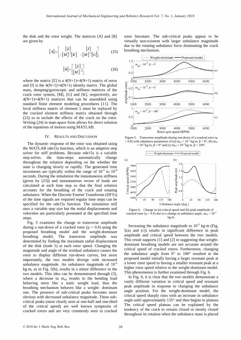
Figure 6. Change in (a) critical speed and (b) peak amplitude of cracked rotor (μ = 0.8) due to a change in unbalance angle. med = 10-3
kg⋅m.
Increasing the unbalance magnitude to 10-3
kg⋅m (Fig.
5(a) and (c)) results in significant difference in peak
amplitude and critical speed between the two models.
This result supports [1] and [2] in suggesting that weight-
dominant breathing models are not accurate around the
critical speed of cracked rotors. Furthermore, changing
the unbalance angle from 0° to 180° resulted in the
proposed model initially having a larger resonant peak at
a lower rotor speed to having a smaller resonant peak at a
higher rotor speed relative to the weight-dominant model.
This phenomenon is further examined through Fig. 6.
In Fig. 6, it is clear that the two models demonstrate a
vastly different variation in critical speed and resonant
peak amplitude in response to changing the unbalance
angle position. For the weight-dominant model, the
critical speed sharply rises with an increase in unbalance
angle until approximately 135° and then begins to plateau.
The critical speed plateau can be explained by the
tendency of the crack to remain closed or mostly closed
throughout its rotation when the unbalance mass is placed
26
International Journal of Mechanical Engineering and Robotics Research Vol. 7, No. 1, January 2018
© 2018 Int. J. Mech. Eng. Rob. Res.

about 180° from the crack. Additionally, the peak
amplitude of the weight-dominant model appears to
change in a sinusoidal manner with an increase in
unbalance angle, whereas the proposed model does not.
Examination of the synchronous (1X) and
supersynchronous (2X and 3X) harmonic components of
the left bearing vibration is an effective tool for detecting
cracks in rotors. Fig. 7 and Fig. 8 compare the change in
the 1X, 2X and 3X vertical harmonic vibration
components obtained during a run-down of the rotor for
both the weight-dominant and proposed models. For Fig.
7, a residual unbalance value of 8×10⁻⁵
kg⋅m
demonstrates a similar change in the harmonic
components of both models. Once again, this similarity is
expected as the two crack breathing models converge
with a decrease in unbalance magnitude. It should be
noted that Fig. 7 highlights a typical change in the
harmonic components of a cracked rotor: the 1X
component is largest at the critical speed, the 2X
component is largest at one-half of the critical speed and
the 3X component is largest at one-third of the critical
speed. In Fig. 8, the residual unbalance is increased to
1×10⁻³
kg⋅m and two models demonstrate a significant
difference in the predicted changes of the 1X, 2X and 3X
harmonic components. Cross-examining Fig. 8(a) with
Fig. 5(a) shows that the 1X components are largest at the
predicted critical speeds (4941 RPM and 4494 RPM for
the weight-dominant and proposed models, respectively).
Interestingly, the 2X harmonic component peaks at
approximately one-half the critical speed for the proposed
model however the weight-dominant model does not. It
appears that due to the large unbalance mass the 2X
harmonic component peaks at approximately 4500 RPM
for the weight-dominant model. Fig. 9 shows the
predicted breathing response of the proposed and weight-
dominant models at 4500 RPM (75 Hz) to provide more
insight into the transient change in 2X component. The
proposed model predicts that placing the large residual
unbalance (1×10⁻³
kg⋅m) at the same location as the crack
(β = 0°) keeps the crack open (this behavior is also seen
in [1] and [3]). On the other hand, the weight-dominant
model predicts the crack to breathe normally (gradually
open and close) since the breathing mechanism is
unaffected by rotating unbalance. As such, prominent 2X
and 3X components for the weight-dominant model are to
be expected, numerically. Since the weight-dominant
model predicts the crack to continue breathing and
instead not remain fully open, the weight-dominant
model appears to not accurately predict the harmonic
components in rotors with large permissible residual
unbalance.
Fig. 10 shows a notable difference in trajectory and
power spectra of the left bearing between the two models
at 4500 RPM. The elliptical trajectory seen for the
proposed model is typical for vibration with insignificant
2X and 3X components. The corollary to this is that the
introduction of significant 2X and 3X components
deviates the orbital trajectory from a circle or ellipse to
more intricate shapes. The proposed model’s trajectory is
larger due to a more significant 1X component at 4500
RPM.
With these findings it is clear that a weight-dominant
breathing mechanism is unsuitable for rotors with large
permissible residual unbalance. If numerical models fail
to correctly estimate the vibration behavior of these rotors
then the models are ineffective as tools for crack
detection.
Figure 7. Change in (a) 1X, (b) 2X and (c) 3X harmonic components
of the left bearing vertical vibration. med = 8×10⁻⁵ kg⋅m and β = 0°.
Figure 8. Change in (a) 1X, (b) 2X and (c) 3X harmonic components
of the left bearing vertical vibration. med = 1×10⁻³ kg⋅m and β = 0°.
Figure 9. Predicted breathing behavior of (a) proposed model and (b)
weight-dominant model at 4500 RPM.
27
International Journal of Mechanical Engineering and Robotics Research Vol. 7, No. 1, January 2018
© 2018 Int. J. Mech. Eng. Rob. Res.

Figure 10. Trajectory and vertical power spectra of the left bearing at 4500 RPM (75 Hz) with eccentric mass placed at β = 0° and med = 10-3.
V. CONCLUSION
This study examines a potential procedure for studying
the vibration behavior of a cracked rotor with large
permissible residual unbalance by removing the
assumption of weight-dominance. Firstly, a new crack
breathing mechanism suitable for predicting the vibration
behavior of a cracked rotor with significant unbalance
was formulated. The difference in vibration predicted
through the proposed unbalance breathing model and the
existing weight-dominant model was then examined.
The predicted vibration behavior of the two models
was shown to have a high degree of similarity when the
unbalance magnitude was relatively low (10-4
kg⋅m).
However, when the unbalance magnitude was increased
to 10-3
kg⋅m, the behaviors diverged. In particular, the
proposed and weight-dominant models provided
distinctly different predictions regarding the change in
critical speed and peak amplitude response when
gradually changing the location of the unbalance mass
from 0° to 180°. As the unbalance angle approached 180°,
the peak amplitude and critical speed response was
shown to vary in an almost sinusoidal manner for the
weight-dominant model. On the other hand, the peak
amplitude response and critical speed for the proposed
model varied in a non-sinusoidal manner and saw a
plateau in values when the unbalance angle was close to
180°.
Additionally, less emphasis on the sub-critical peaks
(occurring at one-half and one-third of the critical speed)
were seen as a result of increasing in unbalance
magnitude due to the unbalance excitation force
dominating the effects of the breathing mechanism.
Examination of the synchronous (1X) and
supersynchronous (2X and 3X) vertical vibration
components of the left bearing further supported that a
reduction of unbalance causes the proposed and weight-
dominant models to converge. For a larger unbalance
magnitude (1×10⁻³
kg⋅m), a highly discernable difference
in the change of the 2X component was predicted
between the two models. The difference is suggested to
be due to the weight-dominant model predicting the crack
to continue breathing normally (gradual opening and
closing of the crack), however the proposed model
suggests the crack remains fully open. The crack
remaining in a single state (always open) is known to be
possible, particularly when the unbalance mass is large
enough and placed at the same position as the crack (β =
0°).
The findings in this study make it clear that the
discrepancy in breathing behavior of the proposed and
weight-dominant models results in a significant
difference in vibration behavior. As such, using a weight-
dominant model for cracked rotors with large permissible
residual unbalance becomes unsuitable for predicting
vibration and for use in crack detection models.
ACKNOWLEDGMENT
We would like to thank Dr. Keqin Xiao for the
continued support and the editing provided for this work.
REFERENCES
[1] N. Bachschmid, P. Pennacchi, and E. Tanzi, Cracked Rotors: A
Survey on Static and Dynamic Behaviour Including Modelling and Diagnosis, Springer Berlin Heidelberg, 2010.
[2] L. Cheng, N. Li, X. F. Chen, and Z. J. He, “The influence of crack
breathing and imbalance orientation angle on the characteristics of the critical speed of a cracked rotor,” Journal of Sound and
Vibration, vol. 330, pp. 2031-2048, 2011. [3] L. Rubio, B. Muñoz-Abella, P. Rubio, and L. Montero, “Quasi-
static numerical study of the breathing mechanism of an elliptical
crack in an unbalanced rotating shaft,” Latin American Journal of Solids & Structures, vol. 11, pp. 2333-2350, 2014.
[4] A. K. Darpe, K. Gupta, and A. Chawla, “Transient response and breathing behaviour of a cracked Jeffcott rotor,” Journal of Sound
and Vibration, vol. 272, pp. 207-243, 2004.
[5] S. El Arem and Q. Nguyen, “Nonlinear dynamics of a rotating shaft with a breathing crack,” Annals of Solid and Structural
Mechanics, vol. 3, pp. 1-14, 2012. [6] I. W. Mayes and W. G. R. Davies, “Analysis of the response of a
multi-rotor-bearing system containing a transverse crack in a
rotor,” Journal of Vibration, Acoustics, Stress, and Reliability in Design, vol. 106, pp. 139-145, 1984.
[7] M. A. Al-Shudeifat, E. A. Butcher, and C. R. Stern, “General harmonic balance solution of a cracked rotor-bearing-disk system
for harmonic and sub-harmonic analysis: Analytical and
experimental approach,” International Journal of Engineering Science, vol. 48, pp. 921-935, 2010.
[8] M. A. Al-Shudeifat and E. A. Butcher, “New breathing functions for the transverse breathing crack of the cracked rotor system:
Approach for critical and subcritical harmonic analysis,” Journal
of Sound and Vibration, vol. 330, pp. 526-544, 2011. [9] C. Guo, M. A. Al-Shudeifat, J. Yan, L. A. Bergman, D. M.
McFarland, and E. A. Butcher, “Application of empirical mode
decomposition to a Jeffcott rotor with a breathing crack,” Journal
of Sound and Vibration, vol. 332, pp. 3881-3892, 2013.
[10] R. D. Cook, Concepts and applications of finite element analysis, 4th Edition, New York: Wiley, 2002.
[11] Y. Ishida and T. Yamamoto, Linear and Nonlinear Rotordynamics: A Modern Treatment with Applications, Wiley,
Hoboken, 2013.
Mr. Joseph Spagnol is a PhD student at the
School of Computing, Engineering and Mathematics at Western Sydney University,
Australia. He was awarded a Bachelor Degree in Mechanical Engineering, at WSU in 2015. His
research has been focused on vibration analysis
of a cracked rotor with an unbalance influenced breathing mechanism.
28
International Journal of Mechanical Engineering and Robotics Research Vol. 7, No. 1, January 2018
© 2018 Int. J. Mech. Eng. Rob. Res.

Dr. Helen Wu is a senior lecturer at the School of Computing, Engineering and Mathematics at
Western Sydney University, Australia. Helen was
awarded a Bachelor Degree in Mechanical Engineering at Sichuan University, China and a
PhD in Civil Engineering at the University of Technology, Sydney. She has twenty years of
experience in teaching, research and consulting
relating to the dynamic response of materials, machines and structures including vibration and condition monitoring.
Associate Professor Chunhui Yang joined the
School of Computing, Engineering and
Mathematics at Western Sydney University, Australia in 2012. He was awarded a PhD in
Mechanical Engineering at the University of Hong Kong in 2002. He has been working in
computational mechanics focusing on
characterization of material properties including multi-scale modeling of materials, structures,
manufacturing and metal surface treatment. He has published more than 100 journal and conference papers.
29
International Journal of Mechanical Engineering and Robotics Research Vol. 7, No. 1, January 2018
© 2018 Int. J. Mech. Eng. Rob. Res.