Embed Size (px)
Citation preview

Vibra Trol
Vibra Trol™
Seismic Bracing Products77
All dimensions in charts and on drawings are in inches. Dimensions shown in parentheses are in millimeters unless otherwise specified.
Disturbing Frequency (RPM) 1/16" 1/8" 1/4" 1/2" 1" 2"
250-299 N/R N/R N/R N/R N/R N/R
300-349 N/R N/R N/R N/R N/R 76%
350-399 N/R N/R N/R N/R N/R 83%
400-449 N/R N/R N/R N/R 74% 87%
450-499 N/R N/R N/R N/R 79% 90%
500-599 N/R N/R N/R N/R 83% 92%
600-699 N/R N/R N/R 75% 89% 95%
700-799 N/R N/R N/R 83% 92% 96%
800-899 N/R N/R N/R 87% 94% 97%
900-999 N/R N/R 78% 90% 95% 98%
1000-1099 N/R N/R 83% 92% 96% 98%
1100-1199 N/R N/R 86% 94% 97% 99%
1200-1299 N/R 83% 89% 95% 97% 99%
1300-1399 N/R 86% 91% 97% 98% 99%
1400-1499 N/R 89% 92% 97% 98% 99%
1500-1599 N/R 90% 93% 97% 99% 99%
1600-1699 N/R 91% 94% 97% 99% 99%
1700-1799 75% 93% 95% 97% 99% 99%
1800-1899 78% 93% 95% 98% 99% 99%
1900-1999 80% 94% 96% 98% 99% 99%
2000-2249 82% 95% 96% 98% 99% 99%
2250-2499 85% 95% 97% 98% 99% 99%
2500-2999 87% 96% 97% 98% 99% 99%
3000-3499 88% 97% 98% 99% 99% 99%
3500-3999 90% 98% 98% 99% 99% 99%
Isolator Deflection
VIBRATION
ISOLATION
EFFICIENCY
Selection
N/R = Not Recommended
Critical Installations 96% to 99% Vibration IsolationEfficiency recommended (only 1% to 4% of disturbing vibration transmitted).
Typical installations: TV and Radio Broadcast Studios, Concert Halls, Libraries, Churches, Hospitals, Schools andUniversities, Hotels, Private Offices, Theaters, RecordingStudios
Standard Installations 90% to 95% Vibration IsolationEfficiency recommended (only 5% to 10% of disturbingvibration transmitted).
Typical installations: Computer Equipment Areas, Restaurants, Shopping Malls, Gymnasiums, Health Clubs and Spas, Sports Arenas, Indoor Swimming Pools, BuildingService Areas, Night Clubs, General Office Buildings
Non-Critical Installations 75% to 89% Vibration Isolation Efficiency recommended (only 11% to 24% of disturbing vibration transmitted).
Typical installations: In factory Offices, Motor VehicleInspection Stations and Facilities, Laundramats, Roller andIce Skating Rinks, Factory Production Areas
For 1/16" (1.6) deflection: Specify B-Line series NNP RibbedNeoprene Pads.
For 1/8" (3.2) deflection: Specify B-Line series CNPCombination Cork and Ribbed Neoprene Pads or B-LineSeries VRP Pads.
For 1/4" (6.3) deflection: Specify B-Line series N NeopreneMountings or B-Line series RH Neoprene Hangers.
For 1/2" (12.7) deflection: Specify B-Line series ND Neoprene Mountings or B-Line series RH Neoprene Hangers.
For 1"-2" (25.4-50.8) deflection: Specify B-Line series HMHoused Spring Mountings or B-Line series OM Open SpringMountings or B-Line series HS Spring Hangers.
For larger deflection requirements, consult factory.
Proper Sizing
Once it is determined as to what type of vibration dampening device is needed, weight loading is the nextcrucial step. As a built in safety measure, take the actual weight of supported pipe or equipment (consider allaccessories - i.e. valves, insulation, brackets, etc...) and multiply by 1.25. Then refer to the sizing chart for theselected product to determine part number.
Sizing: Divide weight of equipment by points of support to determine load requirement per support.
Example: 240 Lb. (90.7 kg) piece of equipment, 4 support points, take 240 x 1.25 = 300 Lbs. (136.1kg)(safety measure), then take 300 ÷ 4 = 75 Lbs. (34.0 kg) Specify appropriate vibration device rated at75 Lbs. (34.0 kg) for each of the support points.
If weight of equipment is unequally proportionate, select mounts to satisfy the weight distribution.
Vibra Trol
Vibra Trol™
78Seismic Bracing Products
All dimensions in charts and on drawings are in inches. Dimensions shown in parentheses are in millimeters unless otherwise specified.
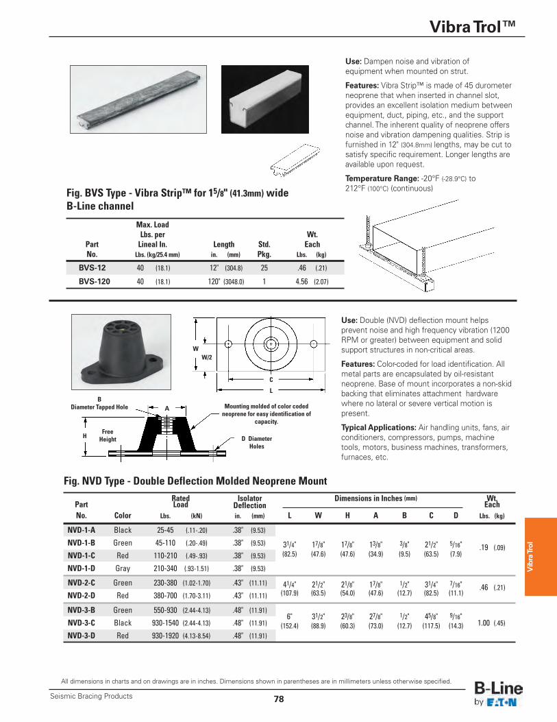
Use: Dampen noise and vibration of equipment when mounted on strut.
Features: Vibra Strip™ is made of 45 durometerneoprene that when inserted in channel slot,provides an excellent isolation medium betweenequipment, duct, piping, etc., and the supportchannel. The inherent quality of neoprene offersnoise and vibration dampening qualities. Strip isfurnished in 12" (304.8mm) lengths, may be cut tosatisfy specific requirement. Longer lengths areavailable upon request.
Temperature Range: -20°F (-28.9°C) to212°F (100°C) (continuous)
Max. Load Lbs. per Wt. Part Lineal In. Length Std. Each No. Lbs. (kg/25.4 mm) in. (mm) Pkg. Lbs. (kg)
BVS-12 40 (18.1) 12" (304.8) 25 .46 (.21)
BVS-120 40 (18.1) 120" (3048.0) 1 4.56 (2.07)
Fig. BVS Type - Vibra Strip™ for 15/8" (41.3mm) wide B-Line channel
Rated Isolator Dimensions in Inches (mm) Wt. Part Load Deflection Each No. Color Lbs. (kN) in. (mm) L W H A B C D Lbs. (kg)
NVD-1-A Black 25-45 (.11-.20) .38" (9.53)
NVD-1-B Green 45-110 (.20-.49) .38" (9.53) 31/4" 17/8" 17/8" 13/8" 3/8" 21/2" 5/16" .19 (.09) NVD-1-C Red 110-210 (.49-.93) .38" (9.53) (82.5) (47.6) (47.6) (34.9) (9.5) (63.5) (7.9)
NVD-1-D Gray 210-340 (.93-1.51) .38" (9.53)
NVD-2-C Green 230-380 (1.02-1.70) .43" (11.11) 41/4" 21/2" 21/8" 17/8" 1/2" 31/4" 7/16" .46 (.21) NVD-2-D Red 380-700 (1.70-3.11) .43" (11.11) (107.9) (63.5) (54.0) (47.6) (12.7) (82.5) (11.1)
NVD-3-B Green 550-930 (2.44-4.13) .48" (11.91) 6" 31/2" 23/8" 27/8" 1/2" 45/8" 9/16"
NVD-3-C Black 930-1540 (2.44-4.13) .48" (11.91) (152.4) (88.9) (60.3) (73.0) (12.7) (117.5) (14.3) 1.00 (.45)
NVD-3-D Red 930-1920 (4.13-8.54) .48" (11.91)
Use: Double (NVD) deflection mount helps prevent noise and high frequency vibration (1200RPM or greater) between equipment and solidsupport structures in non-critical areas.
Features: Color-coded for load identification. Allmetal parts are encapsulated by oil-resistantneoprene. Base of mount incorporates a non-skidbacking that eliminates attachment hardwarewhere no lateral or severe vertical motion ispresent.
Typical Applications: Air handling units, fans, airconditioners, compressors, pumps, machinetools, motors, business machines, transformers,furnaces, etc.
C
W/2
L
W
A
H FreeHeight
BDiameter Tapped Hole Mounting molded of color coded
neoprene for easy identification ofcapacity.
D DiameterHoles
Fig. NVD Type - Double Deflection Molded Neoprene Mount
Vibra Trol
Vibra Trol™
Seismic Bracing Products79
All dimensions in charts and on drawings are in inches. Dimensions shown in parentheses are in millimeters unless otherwise specified.
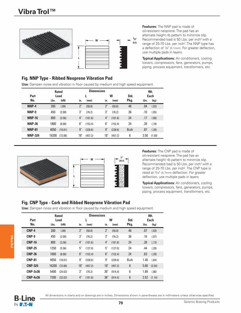
Fig. NNP Type - Ribbed Neoprene Vibration PadUse: Dampen noise and vibration in floor caused by medium and high speed equipment.
Fig. CNP Type - Cork and Ribbed Neoprene Vibration PadUse: Dampen noise and vibration in floor caused by medium and high speed equipment.
W3/8"(9.5)
L
W1"
(25.4)
L
Features: The CNP pad is made of oil-resistant neoprene. The pad has an alternate height rib pattern to minimize slip.Recommended load is 50 Lbs. per inch2 with arange of 25-70 Lbs. per inch2. The CNP type israted at 3/16" (4.7mm) deflection. For greaterdeflection, use multiple pads in layers.
Typical Applications: Air conditioners, coolingtowers, compressors, fans, generators, pumps,piping, process equipment, transformers, etc.
Rated Dimensions Wt. Part Load L W Std. Each No. Lbs. (kN) in. (mm) in. (mm) Pkg. Lbs. (kg)
NNP-4 200 (.89) 2" (50.8) 2" (50.8) 48 .04 (.02)
NNP-9 450 (2.00) 3" (76.2) 3" (76.2) 36 .10 (.05)
NNP-16 800 (3.56) 4" (101.6) 4" (101.6) 24 .17 (.08)
NNP-36 1800 (8.00) 6" (152.4) 6" (152.4) 24 .39 (.18)
NNP-81 4050 (18.01) 9" (228.6) 9" (228.6) Bulk .87 (.39)
NNP-324 16200 (72.06) 18" (457.2) 18" (457.2) 6 3.50 (1.59)
Rated Dimensions Wt. Part Load L W Std. Each No. Lbs. (kN) in. (mm) in. (mm) Pkg. Lbs. (kg)
CNP-4 200 (.89) 2" (50.8) 2" (50.8) 48 .07 (.03)
CNP-9 450 (2.00) 3" (76.2) 3" (76.2) 36 .16 (.07)
CNP-16 800 (3.56) 4" (101.6) 4" (101.6) 24 .28 (.13)
CNP-25 1250 (5.56) 5" (127.0) 5" (127.0) 24 .44 (.20)
CNP-36 1800 (8.00) 6" (152.4) 6" (152.4) 24 .63 (.29)
CNP-81 4050 (18.01) 9" (228.6) 9" (228.6) Bulk 1.40 (.64)
CNP-324 16200 (72.06) 18" (457.2) 18" (457.2) 6 5.60 (2.54)
CNP-3x36 5400 (24.02) 3" (76.2) 36" (914.4) 6 1.89 (.86)
CNP-4x36 7200 (32.02) 4" (101.6) 36" (914.4) 6 2.52 (1.14)
Features: The NNP pad is made of oil-resistant neoprene. The pad has an alternate height rib pattern to minimize slip.Recommended load is 50 Lbs. per inch2 with arange of 25-70 Lbs. per inch2. The NNP type hasa deflection of 1/8" (3.1mm). For greater deflection,use multiple pads in layers.
Typical Applications: Air conditioners, coolingtowers, compressors, fans, generators, pumps,piping, process equipment, transformers, etc.
Vib
ra Tr
ol
Vibra Trol™
80Seismic Bracing Products
All dimensions in charts and on drawings are in inches. Dimensions shown in parentheses are in millimeters unless otherwise specified.
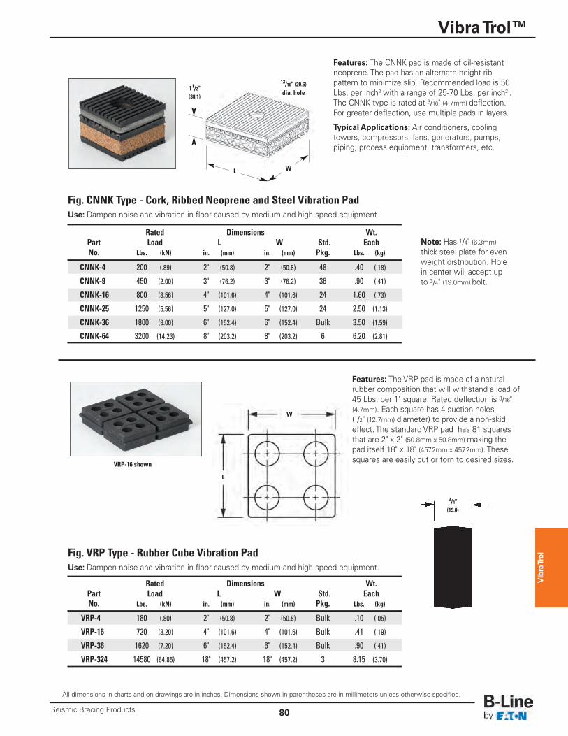
Fig. VRP Type - Rubber Cube Vibration PadUse: Dampen noise and vibration in floor caused by medium and high speed equipment.
Features: The VRP pad is made of a naturalrubber composition that will withstand a load of45 Lbs. per 1" square. Rated deflection is 3/16"(4.7mm). Each square has 4 suction holes(1/2" (12.7mm) diameter) to provide a non-skideffect. The standard VRP pad has 81 squaresthat are 2" x 2" (50.8mm x 50.8mm) making thepad itself 18" x 18" (457.2mm x 457.2mm). Thesesquares are easily cut or torn to desired sizes.
Fig. CNNK Type - Cork, Ribbed Neoprene and Steel Vibration PadUse: Dampen noise and vibration in floor caused by medium and high speed equipment.
13/16" (20.6)dia. hole
L W
Note: Has 1/4" (6.3mm)thick steel plate for evenweight distribution. Holein center will accept upto 3/4" (19.0mm) bolt.
11/2"(38.1)
Rated Dimensions Wt. Part Load L W Std. Each No. Lbs. (kN) in. (mm) in. (mm) Pkg. Lbs. (kg)
CNNK-4 200 (.89) 2" (50.8) 2" (50.8) 48 .40 (.18)
CNNK-9 450 (2.00) 3" (76.2) 3" (76.2) 36 .90 (.41)
CNNK-16 800 (3.56) 4" (101.6) 4" (101.6) 24 1.60 (.73)
CNNK-25 1250 (5.56) 5" (127.0) 5" (127.0) 24 2.50 (1.13)
CNNK-36 1800 (8.00) 6" (152.4) 6" (152.4) Bulk 3.50 (1.59)
CNNK-64 3200 (14.23) 8" (203.2) 8" (203.2) 6 6.20 (2.81)
Features: The CNNK pad is made of oil-resistantneoprene. The pad has an alternate height ribpattern to minimize slip. Recommended load is 50Lbs. per inch2 with a range of 25-70 Lbs. per inch2 .The CNNK type is rated at 3/16" (4.7mm) deflection.For greater deflection, use multiple pads in layers.
Typical Applications: Air conditioners, coolingtowers, compressors, fans, generators, pumps,piping, process equipment, transformers, etc.
Rated Dimensions Wt. Part Load L W Std. Each No. Lbs. (kN) in. (mm) in. (mm) Pkg. Lbs. (kg)
VRP-4 180 (.80) 2" (50.8) 2" (50.8) Bulk .10 (.05)
VRP-16 720 (3.20) 4" (101.6) 4" (101.6) Bulk .41 (.19)
VRP-36 1620 (7.20) 6" (152.4) 6" (152.4) Bulk .90 (.41)
VRP-324 14580 (64.85) 18" (457.2) 18" (457.2) 3 8.15 (3.70)
W
L
3/4"(19.0)
VRP-16 shown
Vibra Trol
Vibra Trol™
Seismic Bracing Products81
All dimensions in charts and on drawings are in inches. Dimensions shown in parentheses are in millimeters unless otherwise specified.
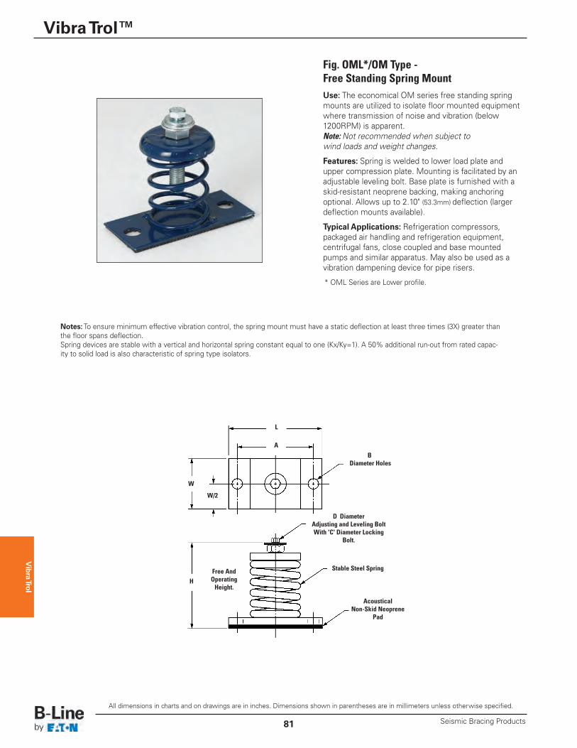
Fig. OML*/OM Type - Free Standing Spring MountUse: The economical OM series free standing springmounts are utilized to isolate floor mounted equipmentwhere transmission of noise and vibration (below1200RPM) is apparent. Note: Not recommended when subject to wind loads and weight changes.
Features: Spring is welded to lower load plate andupper compression plate. Mounting is facilitated by anadjustable leveling bolt. Base plate is furnished with askid-resistant neoprene backing, making anchoringoptional. Allows up to 2.10" (53.3mm) deflection (largerdeflection mounts available).
Typical Applications: Refrigeration compressors,packaged air handling and refrigeration equipment,centrifugal fans, close coupled and base mountedpumps and similar apparatus. May also be used as avibration dampening device for pipe risers.
W
H
W/2
L
A
Free And OperatingHeight.
BDiameter Holes
D Diameter Adjusting and Leveling BoltWith 'C' Diameter Locking
Bolt.
Stable Steel Spring
Acoustical Non-Skid Neoprene
Pad
Notes:To ensure minimum effective vibration control, the spring mount must have a static deflection at least three times (3X) greater thanthe floor spans deflection. Spring devices are stable with a vertical and horizontal spring constant equal to one (Kx/Ky=1). A 50% additional run-out from rated capac-ity to solid load is also characteristic of spring type isolators.
* OML Series are Lower profile.
Vibra Trol
Vibra Trol™
82Seismic Bracing Products
All dimensions in charts and on drawings are in inches. Dimensions shown in parentheses are in millimeters unless otherwise specified.
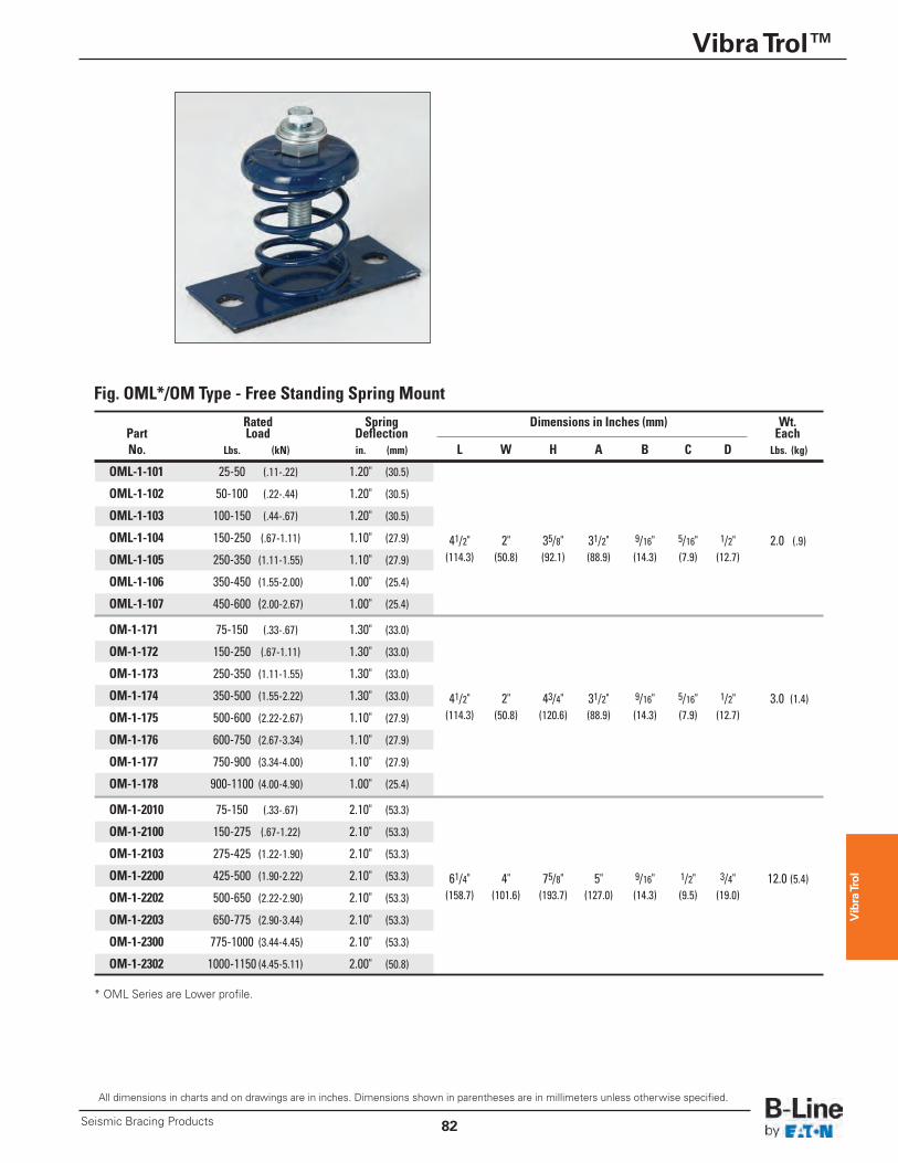
Fig. OML*/OM Type - Free Standing Spring Mount
Rated Spring Dimensions in Inches (mm) Wt. Part Load Deflection Each No. Lbs. (kN) in. (mm) L W H A B C D Lbs. (kg)
OML-1-101 25-50 (.11-.22) 1.20" (30.5)
OML-1-102 50-100 (.22-.44) 1.20" (30.5)
OML-1-103 100-150 (.44-.67) 1.20" (30.5)
OML-1-104 150-250 (.67-1.11) 1.10" (27.9) 41/2" 2" 35/8" 31/2" 9/16" 5/16" 1/2" 2.0 (.9)OML-1-105 250-350 (1.11-1.55) 1.10" (27.9) (114.3) (50.8) (92.1) (88.9) (14.3) (7.9) (12.7)
OML-1-106 350-450 (1.55-2.00) 1.00" (25.4)
OML-1-107 450-600 (2.00-2.67) 1.00" (25.4)
OM-1-171 75-150 (.33-.67) 1.30" (33.0)
OM-1-172 150-250 (.67-1.11) 1.30" (33.0)
OM-1-173 250-350 (1.11-1.55) 1.30" (33.0)
OM-1-174 350-500 (1.55-2.22) 1.30" (33.0) 41/2" 2" 43/4" 31/2" 9/16" 5/16" 1/2" 3.0 (1.4)OM-1-175 500-600 (2.22-2.67) 1.10" (27.9) (114.3) (50.8) (120.6) (88.9) (14.3) (7.9) (12.7)
OM-1-176 600-750 (2.67-3.34) 1.10" (27.9)
OM-1-177 750-900 (3.34-4.00) 1.10" (27.9)
OM-1-178 900-1100 (4.00-4.90) 1.00" (25.4)
OM-1-2010 75-150 (.33-.67) 2.10" (53.3)
OM-1-2100 150-275 (.67-1.22) 2.10" (53.3)
OM-1-2103 275-425 (1.22-1.90) 2.10" (53.3)
OM-1-2200 425-500 (1.90-2.22) 2.10" (53.3) 61/4" 4" 75/8" 5" 9/16" 1/2" 3/4" 12.0 (5.4)OM-1-2202 500-650 (2.22-2.90) 2.10" (53.3) (158.7) (101.6) (193.7) (127.0) (14.3) (9.5) (19.0)
OM-1-2203 650-775 (2.90-3.44) 2.10" (53.3)
OM-1-2300 775-1000 (3.44-4.45) 2.10" (53.3)
OM-1-2302 1000-1150 (4.45-5.11) 2.00" (50.8)
* OML Series are Lower profile.
Vibra Trol
Vibra Trol™
Seismic Bracing Products83
All dimensions in charts and on drawings are in inches. Dimensions shown in parentheses are in millimeters unless otherwise specified.
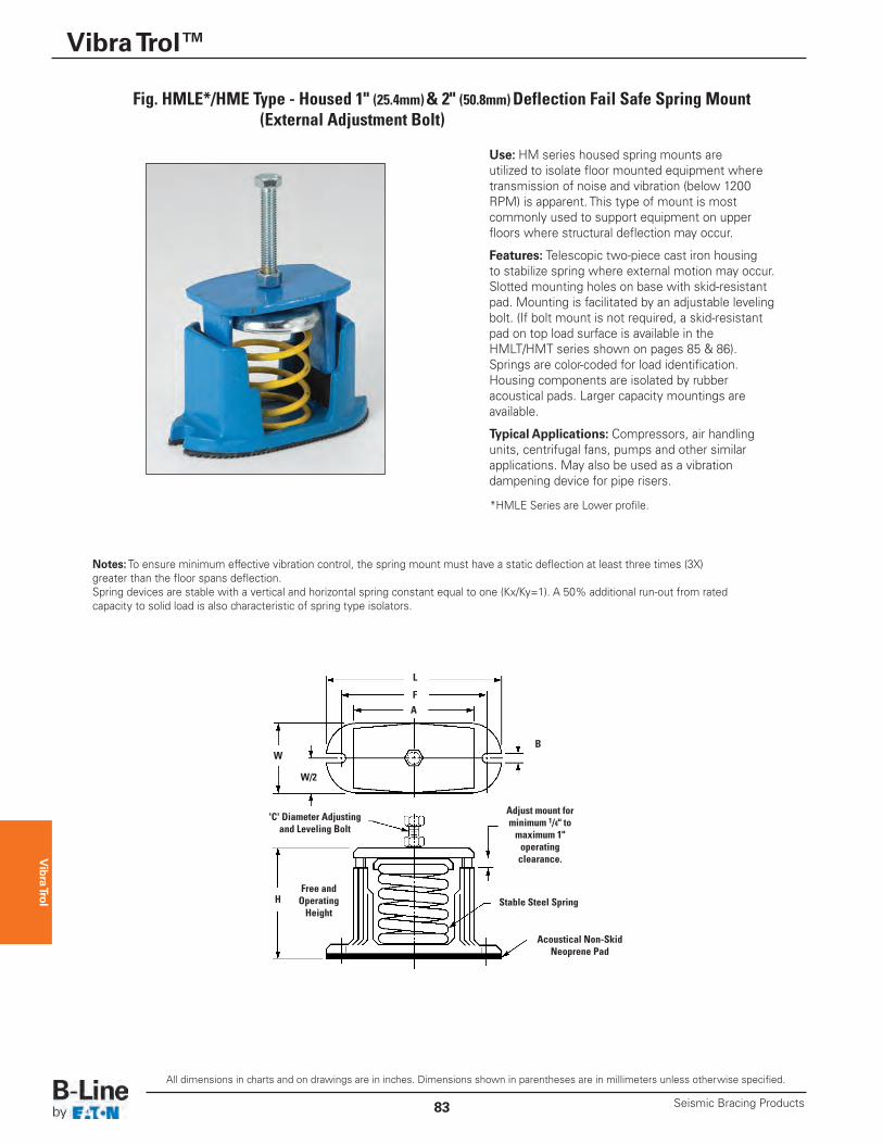
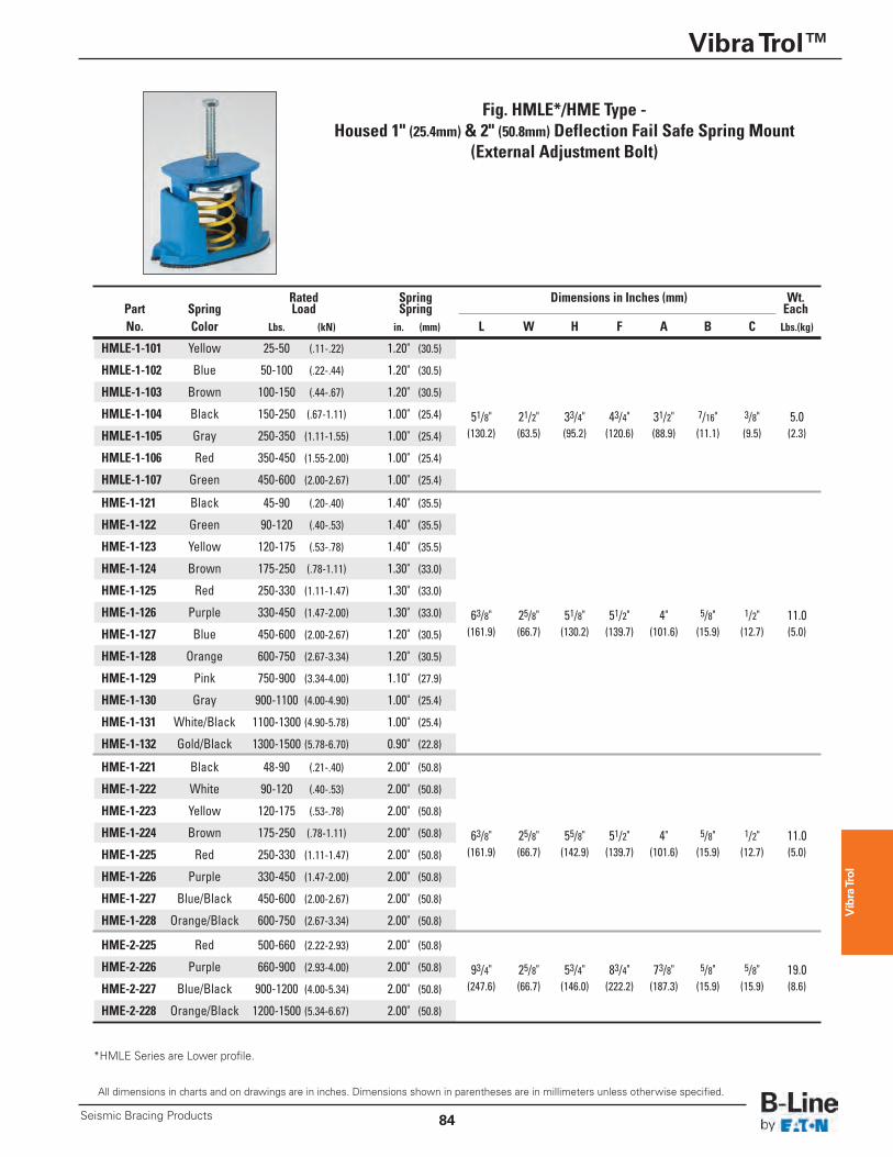
Use: HM series housed spring mounts are utilized to isolate floor mounted equipment wheretransmission of noise and vibration (below 1200RPM) is apparent. This type of mount is mostcommonly used to support equipment on upperfloors where structural deflection may occur.
Features: Telescopic two-piece cast iron housingto stabilize spring where external motion may occur.Slotted mounting holes on base with skid-resistantpad. Mounting is facilitated by an adjustable levelingbolt. (If bolt mount is not required, a skid-resistantpad on top load surface is available in theHMLT/HMT series shown on pages 85 & 86).Springs are color-coded for load identification.Housing components are isolated by rubberacoustical pads. Larger capacity mountings areavailable.
Typical Applications: Compressors, air handlingunits, centrifugal fans, pumps and other similarapplications. May also be used as a vibrationdampening device for pipe risers.
F
BW
W/2
A
H
L
Free and OperatingHeight
Stable Steel Spring
Acoustical Non-SkidNeoprene Pad
Adjust mount forminimum 1/4" tomaximum 1" operating clearance.
'C' Diameter Adjustingand Leveling Bolt
Fig. HMLE*/HME Type - Housed 1" (25.4mm)& 2" (50.8mm)Deflection Fail Safe Spring Mount(External Adjustment Bolt)
Notes:To ensure minimum effective vibration control, the spring mount must have a static deflection at least three times (3X)greater than the floor spans deflection. Spring devices are stable with a vertical and horizontal spring constant equal to one (Kx/Ky=1). A 50% additional run-out from ratedcapacity to solid load is also characteristic of spring type isolators.
*HMLE Series are Lower profile.
Vibra Trol
Vibra Trol™
84Seismic Bracing Products
All dimensions in charts and on drawings are in inches. Dimensions shown in parentheses are in millimeters unless otherwise specified.
*HMLE Series are Lower profile.
Fig. HMLE*/HME Type - Housed 1" (25.4mm) & 2" (50.8mm) Deflection Fail Safe Spring Mount
(External Adjustment Bolt)
Rated Spring Dimensions in Inches (mm) Wt. Part Spring Load Spring Each No. Color Lbs. (kN) in. (mm) L W H F A B C Lbs.(kg)
HMLE-1-101 Yellow 25-50 (.11-.22) 1.20" (30.5)
HMLE-1-102 Blue 50-100 (.22-.44) 1.20" (30.5)
HMLE-1-103 Brown 100-150 (.44-.67) 1.20" (30.5)
HMLE-1-104 Black 150-250 (.67-1.11) 1.00" (25.4) 51/8" 21/2" 33/4" 43/4" 31/2" 7/16" 3/8" 5.0HMLE-1-105 Gray 250-350 (1.11-1.55) 1.00" (25.4) (130.2) (63.5) (95.2) (120.6) (88.9) (11.1) (9.5) (2.3)
HMLE-1-106 Red 350-450 (1.55-2.00) 1.00" (25.4)
HMLE-1-107 Green 450-600 (2.00-2.67) 1.00" (25.4)
HME-1-121 Black 45-90 (.20-.40) 1.40" (35.5)
HME-1-122 Green 90-120 (.40-.53) 1.40" (35.5)
HME-1-123 Yellow 120-175 (.53-.78) 1.40" (35.5)
HME-1-124 Brown 175-250 (.78-1.11) 1.30" (33.0)
HME-1-125 Red 250-330 (1.11-1.47) 1.30" (33.0)
HME-1-126 Purple 330-450 (1.47-2.00) 1.30" (33.0) 63/8" 25/8" 51/8" 51/2" 4" 5/8" 1/2" 11.0HME-1-127 Blue 450-600 (2.00-2.67) 1.20" (30.5) (161.9) (66.7) (130.2) (139.7) (101.6) (15.9) (12.7) (5.0)
HME-1-128 Orange 600-750 (2.67-3.34) 1.20" (30.5)
HME-1-129 Pink 750-900 (3.34-4.00) 1.10" (27.9)
HME-1-130 Gray 900-1100 (4.00-4.90) 1.00" (25.4)
HME-1-131 White/Black 1100-1300 (4.90-5.78) 1.00" (25.4)
HME-1-132 Gold/Black 1300-1500 (5.78-6.70) 0.90" (22.8)
HME-1-221 Black 48-90 (.21-.40) 2.00" (50.8)
HME-1-222 White 90-120 (.40-.53) 2.00" (50.8)
HME-1-223 Yellow 120-175 (.53-.78) 2.00" (50.8)
HME-1-224 Brown 175-250 (.78-1.11) 2.00" (50.8) 63/8" 25/8" 55/8" 51/2" 4" 5/8" 1/2" 11.0HME-1-225 Red 250-330 (1.11-1.47) 2.00" (50.8) (161.9) (66.7) (142.9) (139.7) (101.6) (15.9) (12.7) (5.0)
HME-1-226 Purple 330-450 (1.47-2.00) 2.00" (50.8)
HME-1-227 Blue/Black 450-600 (2.00-2.67) 2.00" (50.8)
HME-1-228 Orange/Black 600-750 (2.67-3.34) 2.00" (50.8)
HME-2-225 Red 500-660 (2.22-2.93) 2.00" (50.8)
HME-2-226 Purple 660-900 (2.93-4.00) 2.00" (50.8) 93/4" 25/8" 53/4" 83/4" 73/8" 5/8" 5/8" 19.0HME-2-227 Blue/Black 900-1200 (4.00-5.34) 2.00" (50.8) (247.6) (66.7) (146.0) (222.2) (187.3) (15.9) (15.9) (8.6)
HME-2-228 Orange/Black 1200-1500 (5.34-6.67) 2.00" (50.8)
Vibra Trol
Vibra Trol™
Seismic Bracing Products85
All dimensions in charts and on drawings are in inches. Dimensions shown in parentheses are in millimeters unless otherwise specified.
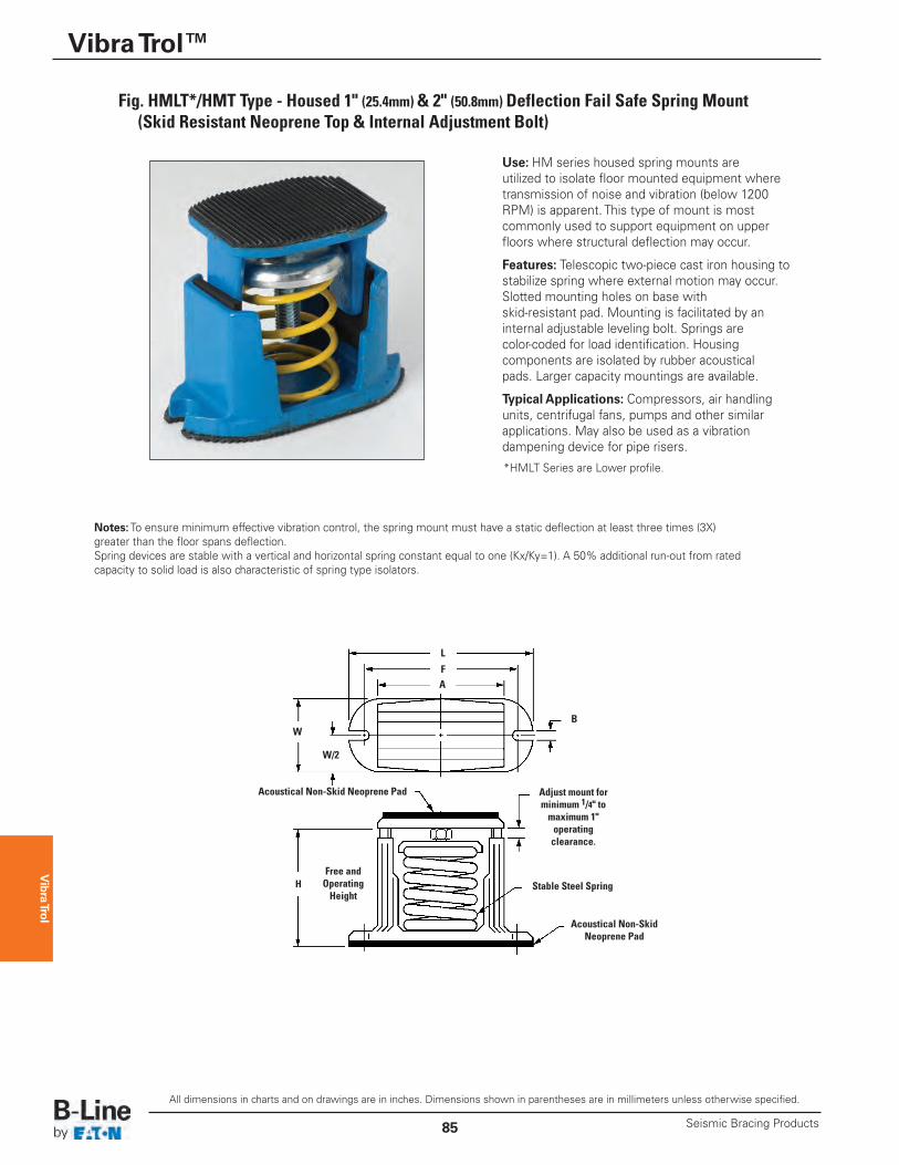
Use: HM series housed spring mounts are utilized to isolate floor mounted equipment wheretransmission of noise and vibration (below 1200RPM) is apparent. This type of mount is mostcommonly used to support equipment on upperfloors where structural deflection may occur.
Features: Telescopic two-piece cast iron housing tostabilize spring where external motion may occur.Slotted mounting holes on base with skid-resistant pad. Mounting is facilitated by aninternal adjustable leveling bolt. Springs are color-coded for load identification. Housing components are isolated by rubber acoustical pads. Larger capacity mountings are available.
Typical Applications: Compressors, air handlingunits, centrifugal fans, pumps and other similarapplications. May also be used as a vibrationdampening device for pipe risers.
F
BW
W/2
A
H
L
Free and OperatingHeight
Stable Steel Spring
Acoustical Non-SkidNeoprene Pad
Acoustical Non-Skid Neoprene Pad Adjust mount forminimum 1/4" tomaximum 1" operating clearance.
Fig. HMLT*/HMT Type - Housed 1" (25.4mm) & 2" (50.8mm) Deflection Fail Safe Spring Mount(Skid Resistant Neoprene Top & Internal Adjustment Bolt)
Notes:To ensure minimum effective vibration control, the spring mount must have a static deflection at least three times (3X)greater than the floor spans deflection. Spring devices are stable with a vertical and horizontal spring constant equal to one (Kx/Ky=1). A 50% additional run-out from ratedcapacity to solid load is also characteristic of spring type isolators.
*HMLT Series are Lower profile.
Vibra Trol
Vibra Trol™
86Seismic Bracing Products
All dimensions in charts and on drawings are in inches. Dimensions shown in parentheses are in millimeters unless otherwise specified.
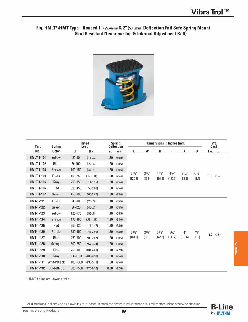
Fig. HMLT*/HMT Type - Housed 1" (25.4mm) & 2" (50.8mm) Deflection Fail Safe Spring Mount(Skid Resistant Neoprene Top & Internal Adjustment Bolt)
*HMLT Series are Lower profile.
Rated Spring Dimensions in Inches (mm) Wt. Part Spring Load Deflection Each No. Color Lbs. (kN) in. (mm) L W H F A B Lbs. (kg)
HMLT-1-101 Yellow 25-50 (.11-.22) 1.20" (30.5)
HMLT-1-102 Blue 50-100 (.22-.44) 1.20" (30.5)
HMLT-1-103 Brown 100-150 (.44-.67) 1.20" (30.5) 51/8" 21/2" 41/8" 43/4" 31/2" 7/16"
HMLT-1-104 Black 150-250 (.67-1.11) 1.00" (25.4) 3.0 (1.4)
HMLT-1-105 Gray 250-350 (1.11-1.55) 1.00" (25.4) (130.2) (63.5) (104.8) (120.6) (88.9) (11.1)
HMLT-1-106 Red 350-450 (1.55-2.00) 1.00" (25.4)
HMLT-1-107 Green 450-600 (2.00-2.67) 1.00" (25.4)
HMT-1-121 Black 45-90 (.20-.40) 1.40" (35.5)
HMT-1-122 Green 90-120 (.40-.53) 1.40" (35.5)
HMT-1-123 Yellow 120-175 (.53-.78) 1.40" (35.5)
HMT-1-124 Brown 175-250 (.78-1.11) 1.30" (33.0)
HMT-1-125 Red 250-330 (1.11-1.47) 1.30" (33.0)
HMT-1-126 Purple 330-450 (1.47-2.00) 1.30" (33.0) 63/8" 25/8" 55/8" 51/2" 4" 5/8" 8.0 (3.6)HMT-1-127 Blue 450-600 (2.00-2.67) 1.20" (30.5) (161.9) (66.7) (142.9) (139.7) (101.6) (15.9)
HMT-1-128 Orange 600-750 (2.67-3.34) 1.20" (30.5)
HMT-1-129 Pink 750-900 (3.34-4.00) 1.10" (27.9)
HMT-1-130 Gray 900-1100 (4.00-4.90) 1.00" (25.4)
HMT-1-131 White/Black 1100-1300 (4.90-5.78) 1.00" (25.4)
HMT-1-132 Gold/Black 1300-1500 (5.78-6.70) 0.90" (22.8)
Vibra Trol
Vibra Trol™
Seismic Bracing Products87
All dimensions in charts and on drawings are in inches. Dimensions shown in parentheses are in millimeters unless otherwise specified.
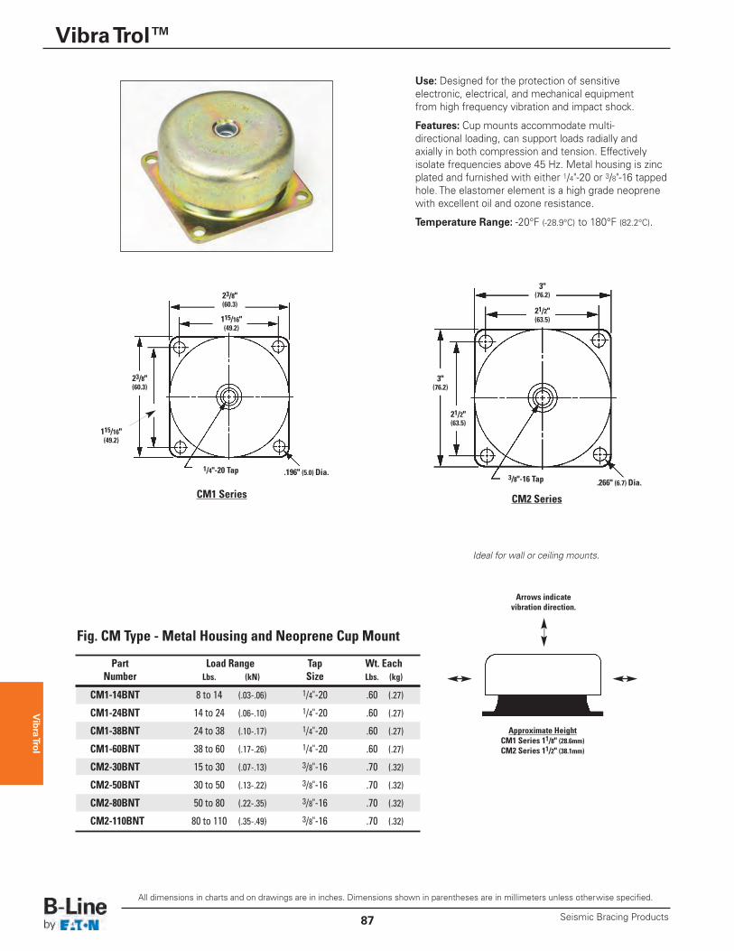
Part Load Range Tap Wt. Each Number Lbs. (kN) Size Lbs. (kg)
CM1-14BNT 8 to 14 (.03-.06) 1/4"-20 .60 (.27)
CM1-24BNT 14 to 24 (.06-.10) 1/4"-20 .60 (.27)
CM1-38BNT 24 to 38 (.10-.17) 1/4"-20 .60 (.27)
CM1-60BNT 38 to 60 (.17-.26) 1/4"-20 .60 (.27)
CM2-30BNT 15 to 30 (.07-.13) 3/8"-16 .70 (.32)
CM2-50BNT 30 to 50 (.13-.22) 3/8"-16 .70 (.32)
CM2-80BNT 50 to 80 (.22-.35) 3/8"-16 .70 (.32)
CM2-110BNT 80 to 110 (.35-.49) 3/8"-16 .70 (.32)
Approximate HeightCM1 Series 11/8" (28.6mm)CM2 Series 11/2" (38.1mm)
Arrows indicatevibration direction.
CM2 SeriesCM1 Series
3"(76.2)
115/16"(49.2)
3"(76.2)23/8"
(60.3)
23/8"(60.3)
3/8"-16 Tap1/4"-20 Tap
.266" (6.7) Dia..196" (5.0) Dia.
Use: Designed for the protection of sensitive electronic, electrical, and mechanical equipment from high frequency vibration and impact shock.
Features: Cup mounts accommodate multi-directional loading, can support loads radially andaxially in both compression and tension. Effectivelyisolate frequencies above 45 Hz. Metal housing is zincplated and furnished with either 1/4"-20 or 3/8"-16 tappedhole. The elastomer element is a high grade neoprenewith excellent oil and ozone resistance.
Temperature Range: -20°F (-28.9°C) to 180°F (82.2°C).
21/2"(63.5)
Ideal for wall or ceiling mounts.
Fig. CM Type - Metal Housing and Neoprene Cup Mount
21/2"(63.5)
115/16"(49.2)
Vibra Trol
Vibra Trol™
88Seismic Bracing Products
All dimensions in charts and on drawings are in inches. Dimensions shown in parentheses are in millimeters unless otherwise specified.
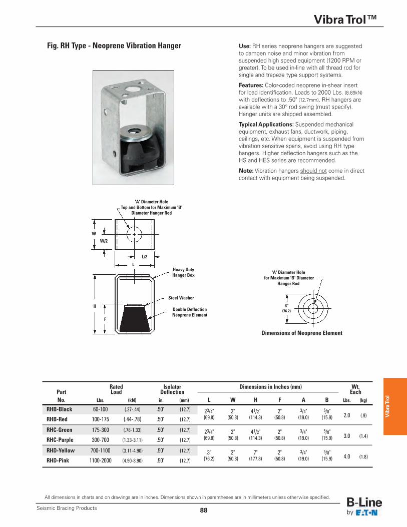
Use: RH series neoprene hangers are suggestedto dampen noise and minor vibration fromsuspended high speed equipment (1200 RPM orgreater). To be used in-line with all thread rod forsingle and trapeze type support systems.
Features: Color-coded neoprene in-shear insertfor load identification. Loads to 2000 Lbs. (8.89kN)with deflections to .50" (12.7mm). RH hangers areavailable with a 30° rod swing (must specify).Hanger units are shipped assembled.
Typical Applications: Suspended mechanicalequipment, exhaust fans, ductwork, piping, ceilings, etc. When equipment is suspended fromvibration sensitive spans, avoid using RH typehangers. Higher deflection hangers such as theHS and HES series are recommended.
Note: Vibration hangers should not come in directcontact with equipment being suspended.
W
W/2
L/2
F
H
LHeavy DutyHanger Box
Steel Washer
Double DeflectionNeoprene Element
'A' Diameter Hole Top and Bottom for Maximum 'B'
Diameter Hanger Rod
3"(76.2)
'A' Diameter Hole for Maximum 'B' Diameter
Hanger Rod
Dimensions of Neoprene Element
Fig. RH Type - Neoprene Vibration Hanger
Rated Isolator Dimensions in Inches (mm) Wt. Part Load Deflection Each No. Lbs. (kN) in. (mm) L W H F A B Lbs. (kg)
RHB-Black 60-100 (.27-.44) .50" (12.7) 23/4" 2" 41/2" 2" 3/4" 5/8" 2.0 (.9) RHB-Red 100-175 (.44-.78) .50" (12.7) (69.8) (50.8) (114.3) (50.8) (19.0) (15.9)
RHC-Green 175-300 (.78-1.33) .50" (12.7) 23/4" 2" 41/2" 2" 3/4" 5/8" 3.0 (1.4) RHC-Purple 300-700 (1.33-3.11) .50" (12.7) (69.8) (50.8) (114.3) (50.8) (19.0) (15.9)
RHD-Yellow 700-1100 (3.11-4.90) .50" (12.7) 3" 2" 7" 2" 3/4" 5/8" 4.0 (1.8) RHD-Pink 1100-2000 (4.90-8.90) .50" (12.7) (76.2) (50.8) (177.8) (50.8) (19.0) (15.9)
Vibra Trol
Vibra Trol™
Seismic Bracing Products89
All dimensions in charts and on drawings are in inches. Dimensions shown in parentheses are in millimeters unless otherwise specified.
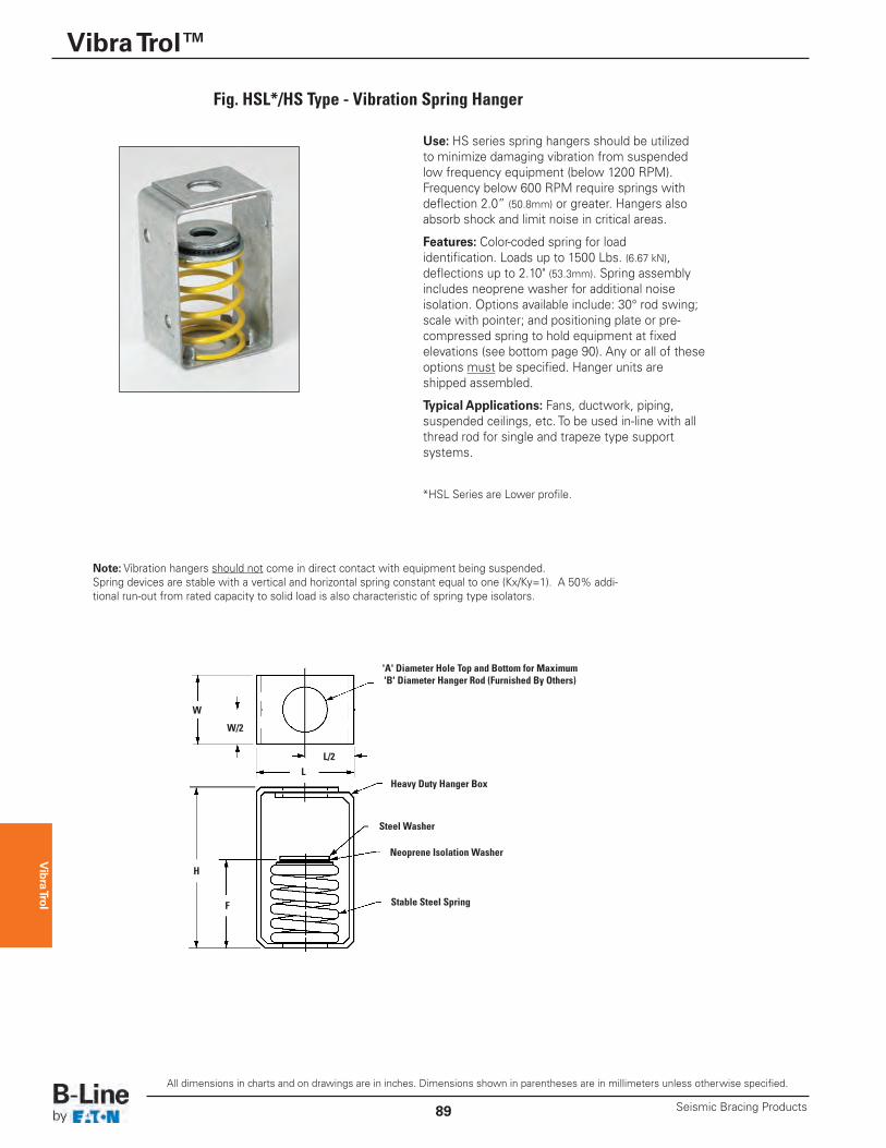
Use: HS series spring hangers should be utilizedto minimize damaging vibration from suspendedlow frequency equipment (below 1200 RPM).Frequency below 600 RPM require springs withdeflection 2.0” (50.8mm) or greater. Hangers alsoabsorb shock and limit noise in critical areas.
Features: Color-coded spring for load identification. Loads up to 1500 Lbs. (6.67 kN),deflections up to 2.10" (53.3mm). Spring assemblyincludes neoprene washer for additional noise isolation. Options available include: 30° rod swing;scale with pointer; and positioning plate or pre-compressed spring to hold equipment at fixedelevations (see bottom page 90). Any or all of theseoptions must be specified. Hanger units areshipped assembled.
Typical Applications: Fans, ductwork, piping,suspended ceilings, etc. To be used in-line with allthread rod for single and trapeze type supportsystems.
F
W
W/2
L/2
H
L
Steel Washer
Stable Steel Spring
Neoprene Isolation Washer
Heavy Duty Hanger Box
'A' Diameter Hole Top and Bottom for Maximum'B' Diameter Hanger Rod (Furnished By Others)
Fig. HSL*/HS Type - Vibration Spring Hanger
*HSL Series are Lower profile.
Note: Vibration hangers should not come in direct contact with equipment being suspended. Spring devices are stable with a vertical and horizontal spring constant equal to one (Kx/Ky=1). A 50% addi-tional run-out from rated capacity to solid load is also characteristic of spring type isolators.
Vibra Trol
Vibra Trol™
90Seismic Bracing Products
All dimensions in charts and on drawings are in inches. Dimensions shown in parentheses are in millimeters unless otherwise specified.
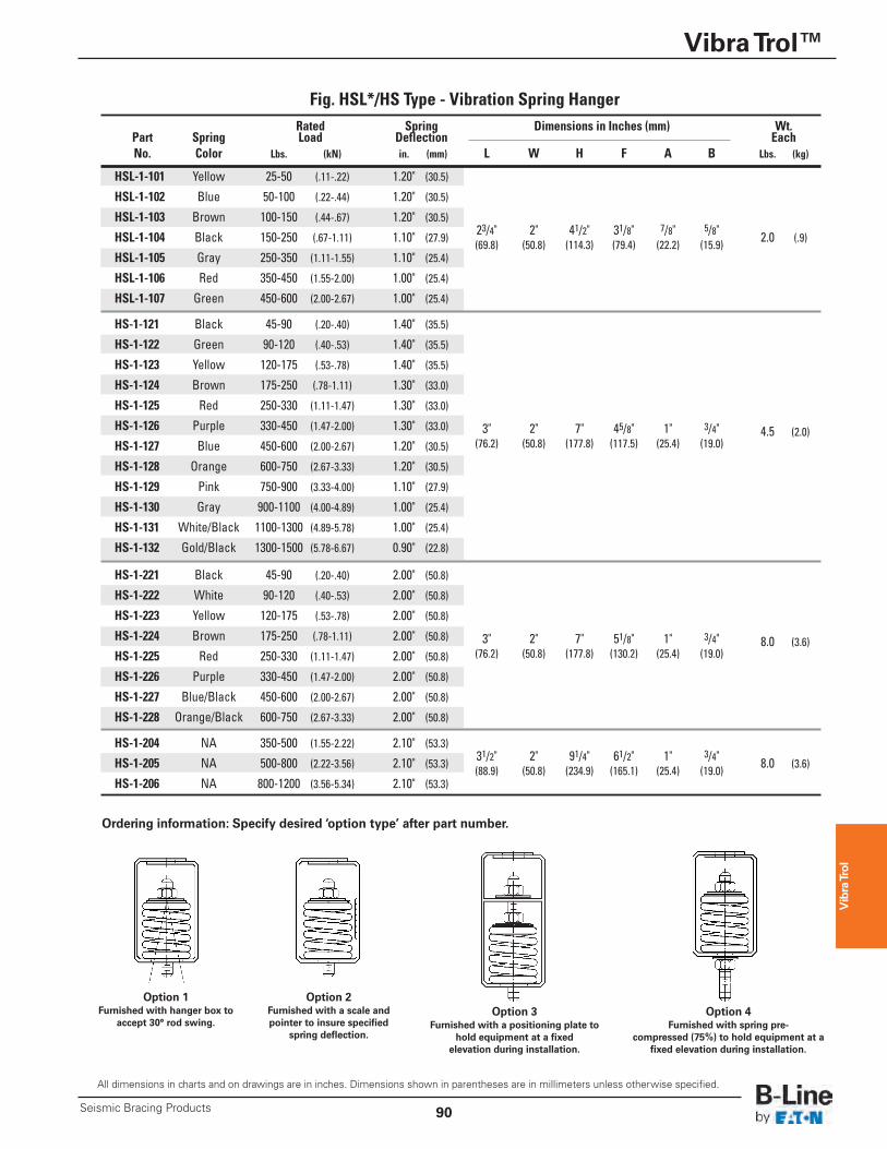
Fig. HSL*/HS Type - Vibration Spring Hanger
Option 1Furnished with hanger box to
accept 30° rod swing.
Option 2Furnished with a scale andpointer to insure specified
spring deflection.
Option 3Furnished with a positioning plate to
hold equipment at a fixed elevation during installation.
Option 4Furnished with spring pre-
compressed (75%) to hold equipment at afixed elevation during installation.
Rated Spring Dimensions in Inches (mm) Wt. Part Spring Load Deflection Each No. Color Lbs. (kN) in. (mm) L W H F A B Lbs. (kg)
HSL-1-101 Yellow 25-50 (.11-.22) 1.20" (30.5)
HSL-1-102 Blue 50-100 (.22-.44) 1.20" (30.5)
HSL-1-103 Brown 100-150 (.44-.67) 1.20" (30.5) 23/4" 2" 41/2" 31/8" 7/8" 5/8"
HSL-1-104 Black 150-250 (.67-1.11) 1.10" (27.9) 2.0 (.9)
HSL-1-105 Gray 250-350 (1.11-1.55) 1.10" (25.4) (69.8) (50.8) (114.3) (79.4) (22.2) (15.9)
HSL-1-106 Red 350-450 (1.55-2.00) 1.00" (25.4)
HSL-1-107 Green 450-600 (2.00-2.67) 1.00" (25.4)
HS-1-121 Black 45-90 (.20-.40) 1.40" (35.5)
HS-1-122 Green 90-120 (.40-.53) 1.40" (35.5)
HS-1-123 Yellow 120-175 (.53-.78) 1.40" (35.5)
HS-1-124 Brown 175-250 (.78-1.11) 1.30" (33.0)
HS-1-125 Red 250-330 (1.11-1.47) 1.30" (33.0)
HS-1-126 Purple 330-450 (1.47-2.00) 1.30" (33.0) 3" 2" 7" 45/8" 1" 3/4" 4.5 (2.0)HS-1-127 Blue 450-600 (2.00-2.67) 1.20" (30.5) (76.2) (50.8) (177.8) (117.5) (25.4) (19.0)
HS-1-128 Orange 600-750 (2.67-3.33) 1.20" (30.5)
HS-1-129 Pink 750-900 (3.33-4.00) 1.10" (27.9)
HS-1-130 Gray 900-1100 (4.00-4.89) 1.00" (25.4)
HS-1-131 White/Black 1100-1300 (4.89-5.78) 1.00" (25.4)
HS-1-132 Gold/Black 1300-1500 (5.78-6.67) 0.90" (22.8)
HS-1-221 Black 45-90 (.20-.40) 2.00" (50.8)
HS-1-222 White 90-120 (.40-.53) 2.00" (50.8)
HS-1-223 Yellow 120-175 (.53-.78) 2.00" (50.8)
HS-1-224 Brown 175-250 (.78-1.11) 2.00" (50.8) 3" 2" 7" 51/8" 1" 3/4" 8.0 (3.6)HS-1-225 Red 250-330 (1.11-1.47) 2.00" (50.8) (76.2) (50.8) (177.8) (130.2) (25.4) (19.0)
HS-1-226 Purple 330-450 (1.47-2.00) 2.00" (50.8)
HS-1-227 Blue/Black 450-600 (2.00-2.67) 2.00" (50.8)
HS-1-228 Orange/Black 600-750 (2.67-3.33) 2.00" (50.8)
HS-1-204 NA 350-500 (1.55-2.22) 2.10" (53.3) 31/2" 2" 91/4" 61/2" 1" 3/4"
HS-1-205 NA 500-800 (2.22-3.56) 2.10" (53.3) 8.0 (3.6)
HS-1-206 NA 800-1200 (3.56-5.34) 2.10" (53.3) (88.9) (50.8) (234.9) (165.1) (25.4) (19.0)
Ordering information: Specify desired ‘option type’ after part number.
Vibra Trol
Vibra Trol™
Seismic Bracing Products91
All dimensions in charts and on drawings are in inches. Dimensions shown in parentheses are in millimeters unless otherwise specified.
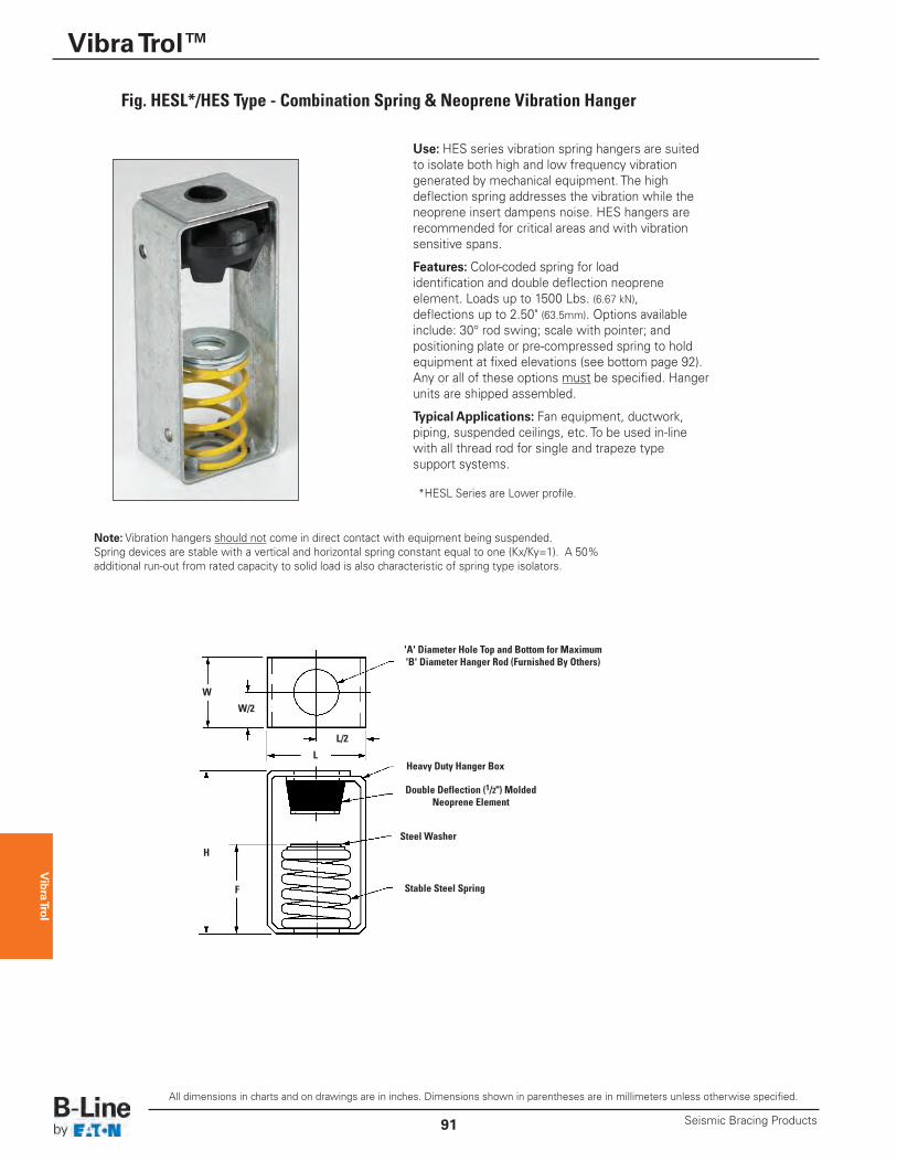
Use: HES series vibration spring hangers are suitedto isolate both high and low frequency vibrationgenerated by mechanical equipment. The highdeflection spring addresses the vibration while theneoprene insert dampens noise. HES hangers arerecommended for critical areas and with vibrationsensitive spans.
Features: Color-coded spring for load identification and double deflection neoprene element. Loads up to 1500 Lbs. (6.67 kN), deflections up to 2.50" (63.5mm). Options availableinclude: 30° rod swing; scale with pointer; andpositioning plate or pre-compressed spring to holdequipment at fixed elevations (see bottom page 92).Any or all of these options must be specified. Hangerunits are shipped assembled.
Typical Applications: Fan equipment, ductwork,piping, suspended ceilings, etc. To be used in-linewith all thread rod for single and trapeze type support systems.
F
W
W/2
L/2
H
L
Steel Washer
Stable Steel Spring
Double Deflection (1/2") MoldedNeoprene Element
Heavy Duty Hanger Box
'A' Diameter Hole Top and Bottom for Maximum'B' Diameter Hanger Rod (Furnished By Others)
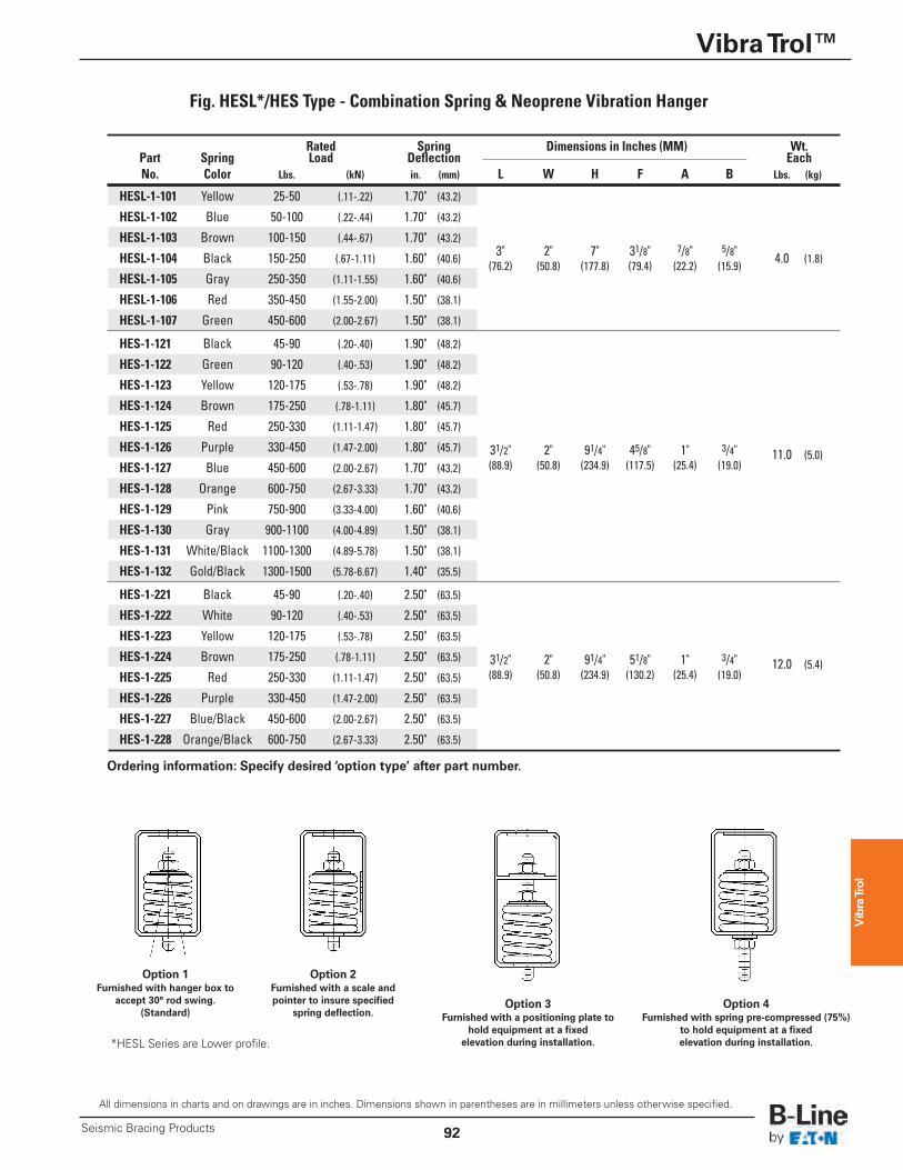
Fig. HESL*/HES Type - Combination Spring & Neoprene Vibration Hanger
Note: Vibration hangers should not come in direct contact with equipment being suspended. Spring devices are stable with a vertical and horizontal spring constant equal to one (Kx/Ky=1). A 50%additional run-out from rated capacity to solid load is also characteristic of spring type isolators.
*HESL Series are Lower profile.
Vibra Trol
Vibra Trol™
92Seismic Bracing Products
All dimensions in charts and on drawings are in inches. Dimensions shown in parentheses are in millimeters unless otherwise specified.
Fig. HESL*/HES Type - Combination Spring & Neoprene Vibration Hanger
Option 1Furnished with hanger box to
accept 30° rod swing.(Standard)
Option 2Furnished with a scale andpointer to insure specified
spring deflection.Option 3
Furnished with a positioning plate tohold equipment at a fixed elevation during installation.
Option 4Furnished with spring pre-compressed (75%)
to hold equipment at a fixed elevation during installation.*HESL Series are Lower profile.
Ordering information: Specify desired ‘option type’ after part number.
Rated Spring Dimensions in Inches (MM) Wt. Part Spring Load Deflection Each No. Color Lbs. (kN) in. (mm) L W H F A B Lbs. (kg)
HESL-1-101 Yellow 25-50 (.11-.22) 1.70" (43.2)
HESL-1-102 Blue 50-100 (.22-.44) 1.70" (43.2)
HESL-1-103 Brown 100-150 (.44-.67) 1.70" (43.2) 3" 2" 7" 31/8" 7/8" 5/8"
HESL-1-104 Black 150-250 (.67-1.11) 1.60" (40.6) 4.0 (1.8)
HESL-1-105 Gray 250-350 (1.11-1.55) 1.60" (40.6) (76.2) (50.8) (177.8) (79.4) (22.2) (15.9)
HESL-1-106 Red 350-450 (1.55-2.00) 1.50" (38.1)
HESL-1-107 Green 450-600 (2.00-2.67) 1.50" (38.1)
HES-1-121 Black 45-90 (.20-.40) 1.90" (48.2)
HES-1-122 Green 90-120 (.40-.53) 1.90" (48.2)
HES-1-123 Yellow 120-175 (.53-.78) 1.90" (48.2)
HES-1-124 Brown 175-250 (.78-1.11) 1.80" (45.7)
HES-1-125 Red 250-330 (1.11-1.47) 1.80" (45.7)
HES-1-126 Purple 330-450 (1.47-2.00) 1.80" (45.7) 31/2" 2" 91/4" 45/8" 1" 3/4" 11.0 (5.0)HES-1-127 Blue 450-600 (2.00-2.67) 1.70" (43.2) (88.9) (50.8) (234.9) (117.5) (25.4) (19.0)
HES-1-128 Orange 600-750 (2.67-3.33) 1.70" (43.2)
HES-1-129 Pink 750-900 (3.33-4.00) 1.60" (40.6)
HES-1-130 Gray 900-1100 (4.00-4.89) 1.50" (38.1)
HES-1-131 White/Black 1100-1300 (4.89-5.78) 1.50" (38.1)
HES-1-132 Gold/Black 1300-1500 (5.78-6.67) 1.40" (35.5)
HES-1-221 Black 45-90 (.20-.40) 2.50" (63.5)
HES-1-222 White 90-120 (.40-.53) 2.50" (63.5)
HES-1-223 Yellow 120-175 (.53-.78) 2.50" (63.5)
HES-1-224 Brown 175-250 (.78-1.11) 2.50" (63.5) 31/2" 2" 91/4" 51/8" 1" 3/4" 12.0 (5.4)HES-1-225 Red 250-330 (1.11-1.47) 2.50" (63.5) (88.9) (50.8) (234.9) (130.2) (25.4) (19.0)
HES-1-226 Purple 330-450 (1.47-2.00) 2.50" (63.5)
HES-1-227 Blue/Black 450-600 (2.00-2.67) 2.50" (63.5)
HES-1-228 Orange/Black 600-750 (2.67-3.33) 2.50" (63.5)
Vibra Trol
Vibra Trol™
Seismic Bracing Products93
All dimensions in charts and on drawings are in inches. Dimensions shown in parentheses are in millimeters unless otherwise specified.
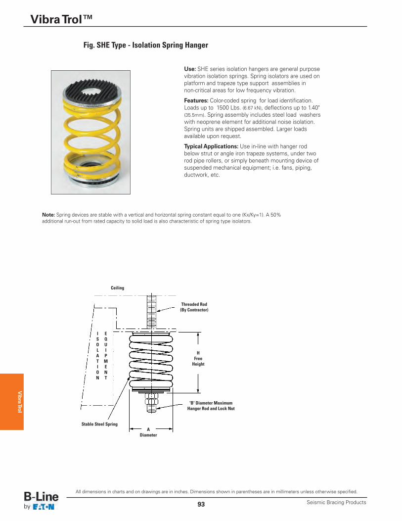
Use: SHE series isolation hangers are general purposevibration isolation springs. Spring isolators are used onplatform and trapeze type support assemblies innon-critical areas for low frequency vibration.
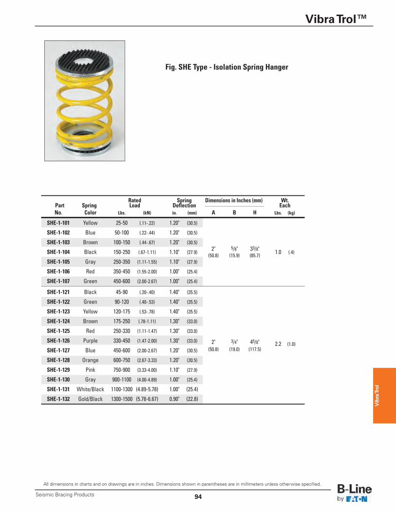
Features: Color-coded spring for load identification.Loads up to 1500 Lbs. (6.67 kN), deflections up to 1.40"(35.5mm). Spring assembly includes steel load washerswith neoprene element for additional noise isolation.Spring units are shipped assembled. Larger loadsavailable upon request.
Typical Applications: Use in-line with hanger rodbelow strut or angle iron trapeze systems, under tworod pipe rollers, or simply beneath mounting device ofsuspended mechanical equipment; i.e. fans, piping,ductwork, etc.
ADiameter
HFree Height
Ceiling
Stable Steel Spring
Threaded Rod(By Contractor)
'B' Diameter MaximumHanger Rod and Lock Nut
Fig. SHE Type - Isolation Spring Hanger
ISOLATION
EQUIPMENT
Note: Spring devices are stable with a vertical and horizontal spring constant equal to one (Kx/Ky=1). A 50%additional run-out from rated capacity to solid load is also characteristic of spring type isolators.
Vibra Trol
Vibra Trol™
94Seismic Bracing Products
All dimensions in charts and on drawings are in inches. Dimensions shown in parentheses are in millimeters unless otherwise specified.
Fig. SHE Type - Isolation Spring Hanger
Rated Spring Dimensions in Inches (mm) Wt. Part Spring Load Deflection Each No. Color Lbs. (kN) in. (mm) A B H Lbs. (kg)
SHE-1-101 Yellow 25-50 (.11-.22) 1.20" (30.5)
SHE-1-102 Blue 50-100 (.22-.44) 1.20" (30.5)
SHE-1-103 Brown 100-150 (.44-.67) 1.20" (30.5) 2" 5/8" 33/8"
SHE-1-104 Black 150-250 (.67-1.11) 1.10" (27.9) 1.0 (.4)
SHE-1-105 Gray 250-350 (1.11-1.55) 1.10" (27.9) (50.8) (15.9) (85.7)
SHE-1-106 Red 350-450 (1.55-2.00) 1.00" (25.4)
SHE-1-107 Green 450-600 (2.00-2.67) 1.00" (25.4)
SHE-1-121 Black 45-90 (.20-.40) 1.40" (35.5)
SHE-1-122 Green 90-120 (.40-.53) 1.40" (35.5)
SHE-1-123 Yellow 120-175 (.53-.78) 1.40" (35.5)
SHE-1-124 Brown 175-250 (.78-1.11) 1.30" (33.0)
SHE-1-125 Red 250-330 (1.11-1.47) 1.30" (33.0)
SHE-1-126 Purple 330-450 (1.47-2.00) 1.30" (33.0) 2" 3/4" 45/8" 2.2 (1.0)SHE-1-127 Blue 450-600 (2.00-2.67) 1.20" (30.5) (50.8) (19.0) (117.5)
SHE-1-128 Orange 600-750 (2.67-3.33) 1.20" (30.5)
SHE-1-129 Pink 750-900 (3.33-4.00) 1.10" (27.9)
SHE-1-130 Gray 900-1100 (4.00-4.89) 1.00" (25.4)
SHE-1-131 White/Black 1100-1300 (4.89-5.78) 1.00" (25.4)
SHE-1-132 Gold/Black 1300-1500 (5.78-6.67) 0.90" (22.8)
Vibra Trol
Vibra Trol™
Seismic Bracing Products95
All dimensions in charts and on drawings are in inches. Dimensions shown in parentheses are in millimeters unless otherwise specified.
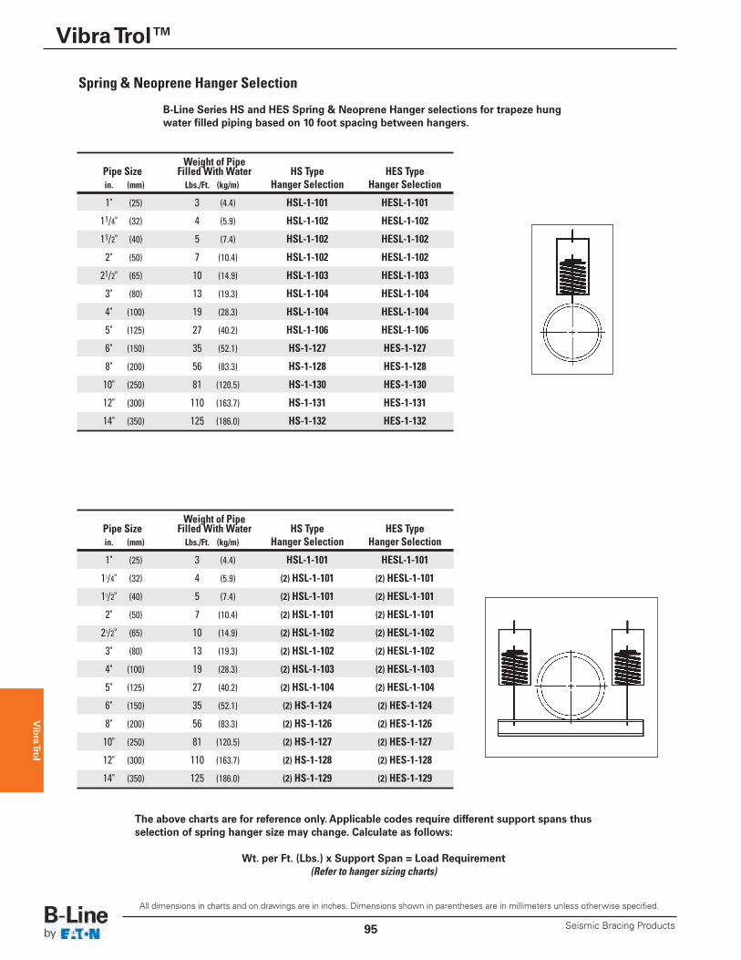
B-Line Series HS and HES Spring & Neoprene Hanger selections for trapeze hungwater filled piping based on 10 foot spacing between hangers.
The above charts are for reference only. Applicable codes require different support spans thusselection of spring hanger size may change. Calculate as follows:
Wt. per Ft. (Lbs.) x Support Span = Load Requirement(Refer to hanger sizing charts)
Weight of Pipe Pipe Size Filled With Water HS Type HES Type in. (mm) Lbs./Ft. (kg/m) Hanger Selection Hanger Selection
1" (25) 3 (4.4) HSL-1-101 HESL-1-101
11/4" (32) 4 (5.9) HSL-1-102 HESL-1-102
11/2" (40) 5 (7.4) HSL-1-102 HESL-1-102
2" (50) 7 (10.4) HSL-1-102 HESL-1-102
21/2" (65) 10 (14.9) HSL-1-103 HESL-1-103
3" (80) 13 (19.3) HSL-1-104 HESL-1-104
4" (100) 19 (28.3) HSL-1-104 HESL-1-104
5" (125) 27 (40.2) HSL-1-106 HESL-1-106
6" (150) 35 (52.1) HS-1-127 HES-1-127
8" (200) 56 (83.3) HS-1-128 HES-1-128
10" (250) 81 (120.5) HS-1-130 HES-1-130
12" (300) 110 (163.7) HS-1-131 HES-1-131
14" (350) 125 (186.0) HS-1-132 HES-1-132
Weight of Pipe Pipe Size Filled With Water HS Type HES Type in. (mm) Lbs./Ft. (kg/m) Hanger Selection Hanger Selection
1" (25) 3 (4.4) HSL-1-101 HESL-1-101
11/4" (32) 4 (5.9) (2) HSL-1-101 (2) HESL-1-101
11/2" (40) 5 (7.4) (2) HSL-1-101 (2) HESL-1-101
2" (50) 7 (10.4) (2) HSL-1-101 (2) HESL-1-101
21/2" (65) 10 (14.9) (2) HSL-1-102 (2) HESL-1-102
3" (80) 13 (19.3) (2) HSL-1-102 (2) HESL-1-102
4" (100) 19 (28.3) (2) HSL-1-103 (2) HESL-1-103
5" (125) 27 (40.2) (2) HSL-1-104 (2) HESL-1-104
6" (150) 35 (52.1) (2) HS-1-124 (2) HES-1-124
8" (200) 56 (83.3) (2) HS-1-126 (2) HES-1-126
10" (250) 81 (120.5) (2) HS-1-127 (2) HES-1-127
12" (300) 110 (163.7) (2) HS-1-128 (2) HES-1-128
14" (350) 125 (186.0) (2) HS-1-129 (2) HES-1-129
Spring & Neoprene Hanger Selection
Vibra Trol
Vibra Trol™
96Seismic Bracing Products
All dimensions in charts and on drawings are in inches. Dimensions shown in parentheses are in millimeters unless otherwise specified.
B-LINE
B-LINE
BVP150
BVP150
1 1/2”
I.P
1 1/2” I.P..
C
A
B
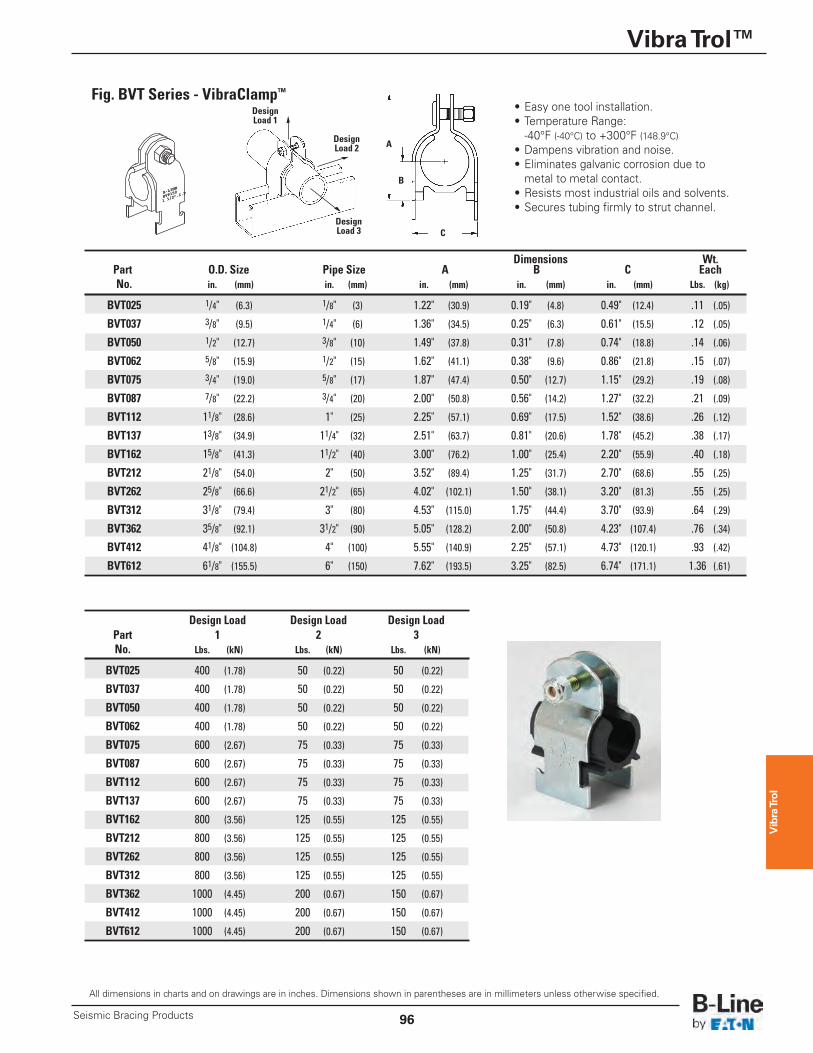
Fig. BVT Series - VibraClamp™• Easy one tool installation.• Temperature Range: -40°F (-40°C) to +300°F (148.9°C)• Dampens vibration and noise.• Eliminates galvanic corrosion due to metal to metal contact.• Resists most industrial oils and solvents.• Secures tubing firmly to strut channel.
Dimensions Wt. Part O.D. Size Pipe Size A B C Each No. in. (mm) in. (mm) in. (mm) in. (mm) in. (mm) Lbs. (kg)
BVT025 1/4" (6.3) 1/8" (3) 1.22" (30.9) 0.19" (4.8) 0.49" (12.4) .11 (.05)
BVT037 3/8" (9.5) 1/4" (6) 1.36" (34.5) 0.25" (6.3) 0.61" (15.5) .12 (.05)
BVT050 1/2" (12.7) 3/8" (10) 1.49" (37.8) 0.31" (7.8) 0.74" (18.8) .14 (.06)
BVT062 5/8" (15.9) 1/2" (15) 1.62" (41.1) 0.38" (9.6) 0.86" (21.8) .15 (.07)
BVT075 3/4" (19.0) 5/8" (17) 1.87" (47.4) 0.50" (12.7) 1.15" (29.2) .19 (.08)
BVT087 7/8" (22.2) 3/4" (20) 2.00" (50.8) 0.56" (14.2) 1.27" (32.2) .21 (.09)
BVT112 11/8" (28.6) 1" (25) 2.25" (57.1) 0.69" (17.5) 1.52" (38.6) .26 (.12)
BVT137 13/8" (34.9) 11/4" (32) 2.51" (63.7) 0.81" (20.6) 1.78" (45.2) .38 (.17)
BVT162 15/8" (41.3) 11/2" (40) 3.00" (76.2) 1.00" (25.4) 2.20" (55.9) .40 (.18)
BVT212 21/8" (54.0) 2" (50) 3.52" (89.4) 1.25" (31.7) 2.70" (68.6) .55 (.25)
BVT262 25/8" (66.6) 21/2" (65) 4.02" (102.1) 1.50" (38.1) 3.20" (81.3) .55 (.25)
BVT312 31/8" (79.4) 3" (80) 4.53" (115.0) 1.75" (44.4) 3.70" (93.9) .64 (.29)
BVT362 35/8" (92.1) 31/2" (90) 5.05" (128.2) 2.00" (50.8) 4.23" (107.4) .76 (.34)
BVT412 41/8" (104.8) 4" (100) 5.55" (140.9) 2.25" (57.1) 4.73" (120.1) .93 (.42)
BVT612 61/8" (155.5) 6" (150) 7.62" (193.5) 3.25" (82.5) 6.74" (171.1) 1.36 (.61)
Design Load Design Load Design Load Part 1 2 3 No. Lbs. (kN) Lbs. (kN) Lbs. (kN)
BVT025 400 (1.78) 50 (0.22) 50 (0.22)
BVT037 400 (1.78) 50 (0.22) 50 (0.22)
BVT050 400 (1.78) 50 (0.22) 50 (0.22)
BVT062 400 (1.78) 50 (0.22) 50 (0.22)
BVT075 600 (2.67) 75 (0.33) 75 (0.33)
BVT087 600 (2.67) 75 (0.33) 75 (0.33)
BVT112 600 (2.67) 75 (0.33) 75 (0.33)
BVT137 600 (2.67) 75 (0.33) 75 (0.33)
BVT162 800 (3.56) 125 (0.55) 125 (0.55)
BVT212 800 (3.56) 125 (0.55) 125 (0.55)
BVT262 800 (3.56) 125 (0.55) 125 (0.55)
BVT312 800 (3.56) 125 (0.55) 125 (0.55)
BVT362 1000 (4.45) 200 (0.67) 150 (0.67)
BVT412 1000 (4.45) 200 (0.67) 150 (0.67)
BVT612 1000 (4.45) 200 (0.67) 150 (0.67)
DesignLoad 2
DesignLoad 1
DesignLoad 3
Vibra Trol
Vibra Trol™
Seismic Bracing Products97
All dimensions in charts and on drawings are in inches. Dimensions shown in parentheses are in millimeters unless otherwise specified.
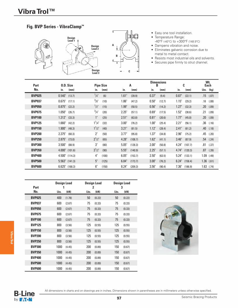
Fig. BVP Series - VibraClamp™
• Easy one tool installation.• Temperature Range: -40°F (-40°C) to +300°F (148.9°C)• Dampens vibration and noise.• Eliminates galvanic corrosion due to metal to metal contact.• Resists most industrial oils and solvents.• Secures pipe firmly to strut channel.
Dimensions Wt. Part O.D. Size Pipe Size A B C Each No. in. (mm) in. (mm) in. (mm) in. (mm) in. (mm) Lbs. (kg)
BVP025 0.540" (13.7) 1/4" (6) 1.61" (39.9) 0.37" (9.4) 0.87" (22.1) .15 (.07)
BVP037 0.675" (17.1) 3/8" (10) 1.86" (47.2) 0.50" (12.7) 1.15" (29.2) .18 (.08)
BVP050 0.875" (22.2) 1/2" (15) 1.99" (50.5) 0.56" (14.2) 1.27" (32.3) .20 (.09)
BVP075 1.050" (26.7) 3/4" (20) 2.25" (57.1) 0.69" (17.5) 1.52" (38.6) .21 (.09)
BVP100 1.312" (33.3) 1" (25) 2.51" (63.8) 0.81" (20.6) 1.77" (45.0) .20 (.09)
BVP125 1.660" (42.2) 11/4" (32) 3.00" (76.2) 1.00" (25.4) 2.21" (56.1) .36 (.16)
BVP150 1.900" (48.3) 11/2" (40) 3.21" (81.5) 1.12" (28.4) 2.41" (61.2) .40 (.18)
BVP200 2.375" (60.3) 2" (50) 3.77" (95.8) 1.37" (34.8) 2.96" (75.2) .45 (.20)
BVP250 2.875" (73.0) 21/2" (65) 4.28" (108.7) 1.62" (41.1) 3.46" (87.9) .54 (.24)
BVP300 3.500" (88.9) 3" (80) 5.05" (128.3) 2.00" (50.8) 4.24" (107.7) .81 (.37)
BVP350 4.000" (101.6) 31/2" (90) 5.55" (140.9) 2.25" (57.1) 4.74" (120.3) .87 (.39)
BVP400 4.500" (114.3) 4" (100) 6.05" (153.7) 2.50" (63.5) 5.24" (133.1) 1.09 (.49)
BVP500 5.563" (141.3) 5" (125) 6.84" (173.7) 3.00" (76.2) 6.24" (158.4) 1.36 (.61)
BVP600 6.625" (168.3) 6" (150) 8.24" (209.3) 3.56" (90.4) 7.36" (186.9) 1.63 (.74)
Design Load Design Load Design Load Part 1 2 3 No. Lbs. (kN) Lbs. (kN) Lbs. (kN)
BVP025 400 (1.78) 50 (0.22) 50 (0.22)
BVP037 600 (2.67) 75 (0.33) 75 (0.33)
BVP050 600 (2.67) 75 (0.33) 75 (0.33)
BVP075 600 (2.67) 75 (0.33) 75 (0.33)
BVP100 600 (2.67) 75 (0.33) 75 (0.33)
BVP125 800 (3.56) 125 (0.55) 125 (0.55)
BVP150 800 (3.56) 125 (0.55) 125 (0.55)
BVP200 800 (3.56) 125 (0.55) 125 (0.55)
BVP250 800 (3.56) 125 (0.55) 125 (0.55)
BVP300 1000 (4.45) 200 (0.89) 150 (0.67)
BVP350 1000 (4.45) 200 (0.89) 150 (0.67)
BVP400 1000 (4.45) 200 (0.89) 150 (0.67)
BVP500 1000 (4.45) 200 (0.89) 150 (0.67)
BVP600 1000 (4.45) 200 (0.89) 150 (0.67)
B-LINE
B-LINE
BVP150
BVP150
1 1/2”
I.P
1 1/2” I.P..
C
A
B
DesignLoad 2
DesignLoad 1
DesignLoad 3
Vibra Trol
Vibra Trol™
98Seismic Bracing Products
All dimensions in charts and on drawings are in inches. Dimensions shown in parentheses are in millimeters unless otherwise specified.
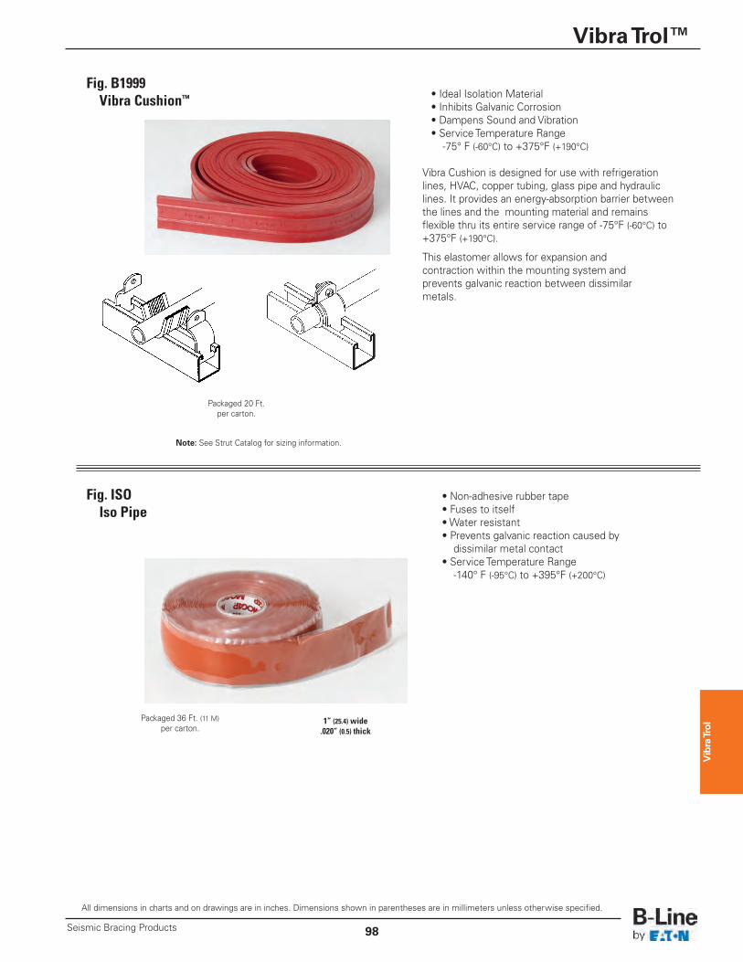
• Ideal Isolation Material• Inhibits Galvanic Corrosion• Dampens Sound and Vibration• Service Temperature Range-75° F (-60°C) to +375°F (+190°C)
Vibra Cushion is designed for use with refrigerationlines, HVAC, copper tubing, glass pipe and hydrauliclines. It provides an energy-absorption barrier betweenthe lines and the mounting material and remainsflexible thru its entire service range of -75°F (-60°C) to+375°F (+190°C).
This elastomer allows for expansion and contraction within the mounting system and prevents galvanic reaction between dissimilar metals.
Fig. B1999Vibra Cushion™
Packaged 20 Ft.per carton.
• Non-adhesive rubber tape• Fuses to itself• Water resistant• Prevents galvanic reaction caused by dissimilar metal contact
• Service Temperature Range-140° F (-95°C) to +395°F (+200°C)
Fig. ISOIso Pipe
Packaged 36 Ft. (11 M)per carton.
1” (25.4) wide.020” (0.5) thick
Note: See Strut Catalog for sizing information.