Embed Size (px)
Citation preview
VHF/AM MOBILE TRANSCEIVER
MODEL TiL-91-DE
7 WATT MOBILE SYSTEM NO 910200 (TMS-150)
Installation and Operating Instructions
Til Document No.94RE146
Rev. A
October 2001
Technisonic Industries Limited240 Traders Blvd., Mississauga, Ontario L4Z 1P4 Tel:(905)890-2113 Fax:(905)890-5338
www.til.ca
A Page
WARNING
Do not make physical contact with antenna when transmitter is on. This unit can produce up to 30 watts ofpower (depending on configuration) when operated in high power mode.
CAUTION
This unit contains static sensitive devices. Wear a grounded wrist strap and/or conductive gloves whenhandling printed circuit boards.
WARRANTY INFORMATION
The Base Stations, Model 91-DE series and Model Til 90-6R series are under warranty for one year fromdate of purchase. Failed units caused by defective parts, or workmanship should be returned to:
Technisonic Industries Limited240 Traders Blvd.Mississauga, Amherst,NY,USAOntario L4Z 1W7
Tel: (905) 890-2113 Tel: (716) 691-0669Fax: (905) 890-5338
i
TABLE OF CONTENTS
Section Title Page
1 GENERAL DESCRIPTION 1-1
1.1 Introduction 1-11.1.1 Purpose of the System 1-11.1.2 Modes of Operation 1-21.2 Technical Summary 1-9
2 INSTALLATION INFORMATION 2-1
2.1 Introduction 2-12.2 Transceiver Location 2-12.3 Vehicle Power Supply 2-12.4 Power Input Cable Assembly 2-12.5 Antenna Assembly 2-22.5.1 Antenna Location 2-22.5.2 Antenna Installation 2-22.6 Mounting Bracket Installation 2-22.7 Transceiver Installation 2-22.8 Microphone Installation 2-32.9 Optional External Loudspeaker or Headphone 2-32.9.1 External Loudspeaker 2-32.9.2 Headset 2-32.10 Operational Check 2-3
3 OPERATING INSTRUCTIONS 3-1
3.1 Introduction 3-13.2 Operator's Switches, Controls and Indicators 3-13.3 Front Panel Keypad Operation 3-53.4 Fixed Channel Frequency Set Up 3-12
ii
LIST OF TABLES
Table No. Title Page
1-1 Leading Particulars 1-9
3-1 Operator's Switches, Controls and Indicators 3-2
3-2 Channel/Function Selector Keypad 3-5
LIST OF ILLUSTRATIONS
Figure No. Title Page
1-1 Transceiver - General View 1-4
1-2 Transceiver with Mounting Bracket - General View 1-5
1-3 Power Input Cable Assembly - General View 1-6
1-4 Microphone Assembly - General View 1-7
1-5 Antenna Assembly - General View 1-8
3-1 Transceiver Front Panel Layout 3-2
3-2 Fixed Channel Jumper Locations 3-11
1-1
SECTION 1
GENERAL DESCRIPTION
1.1 INTRODUCTION
VHF/AM Mobile Transceiver System 910200 (Item No. TMS-150), manufactured by TechnisonicIndustries Limited, is a low power VHF/AM Transceiver, complete with Mounting Bracket, PowerInput Cable, Microphone and Antenna.
1.1.1 PURPOSE OF THE SYSTEM
(1) Intended Purpose and Use - The system is intended for installation in airport service vehicles, such as cars, snowplows, and grass cutters, to allow ground control over suchvehicles while they are negotiating aircraft manouvering areas.
(2) Brief Description of System Units - VHF/AM Mobile Transceiver System 910200 consistsof the following items:
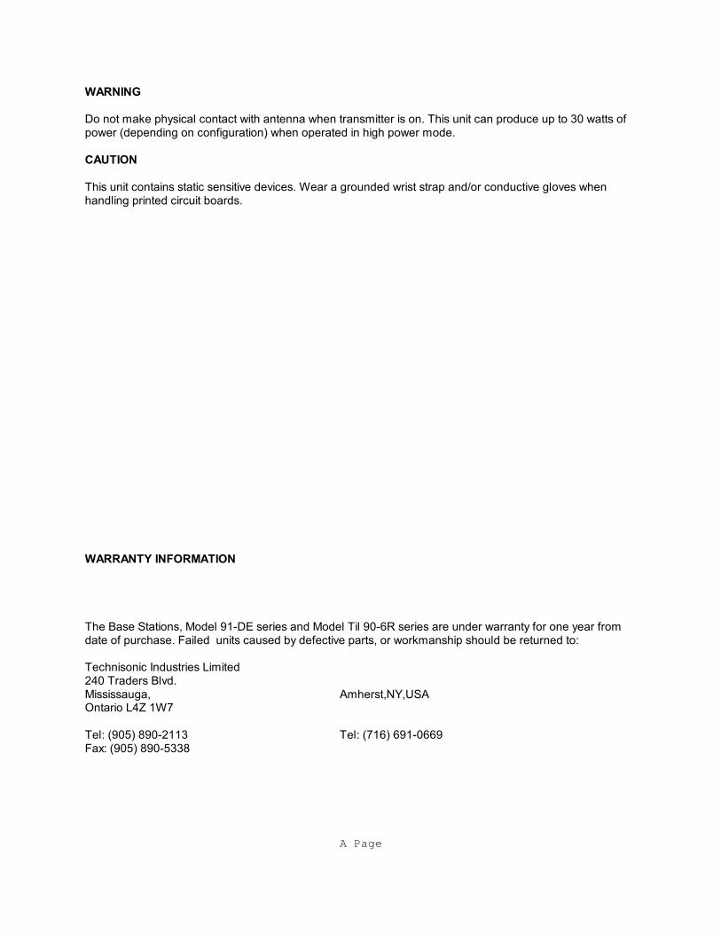
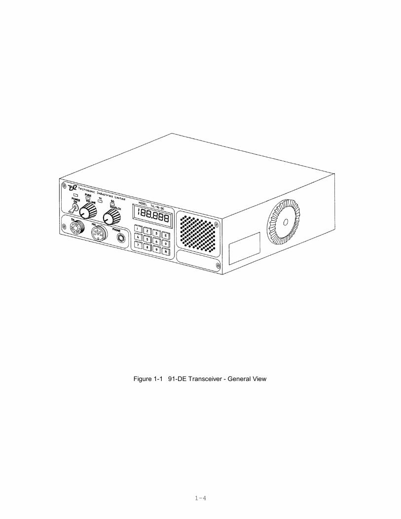
(a) Transceiver Model 91-DE, Part Number 901006-2, Series 1, is a low power VHF/AMtransceiver which operates in simplex and allows quick keypad access and LCD displayof the frequency range 117.975MHz to 138.000MHz with 25kHz channel spacing. Thetransceiver operates from a 12 volts dc nominal vehicle power supply (negative groundonly). An optional extra cost dc to dc convertor P/N 863118-1 can be installed in thetransceiver to allow operation from an input supply from 10.8 to 30.0 Vdc. A generalview of the transceiver is given in Figure 1-1. The transceiver is normally located underthe dashboard of a vehicle using a mounting bracket and mounting hardware.
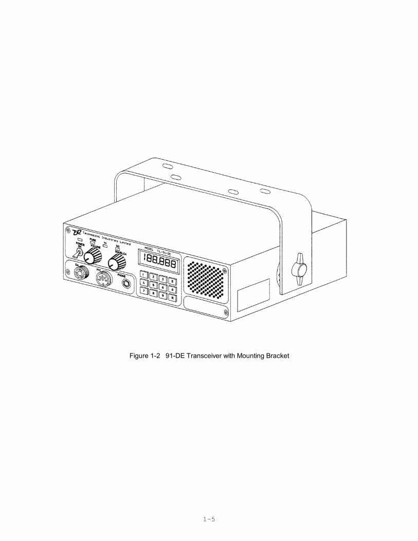
(b) Mounting Bracket, Part Number 913053-1, is a U-shaped aluminum alloy bracket which, together with items of hardware included in Mounting Hardware Kit P/N 869024-1, is used to mount the transceiver under the dashboard of a vehicle.
A view of the transceiver with mounting bracket is given in Figure 1-2.
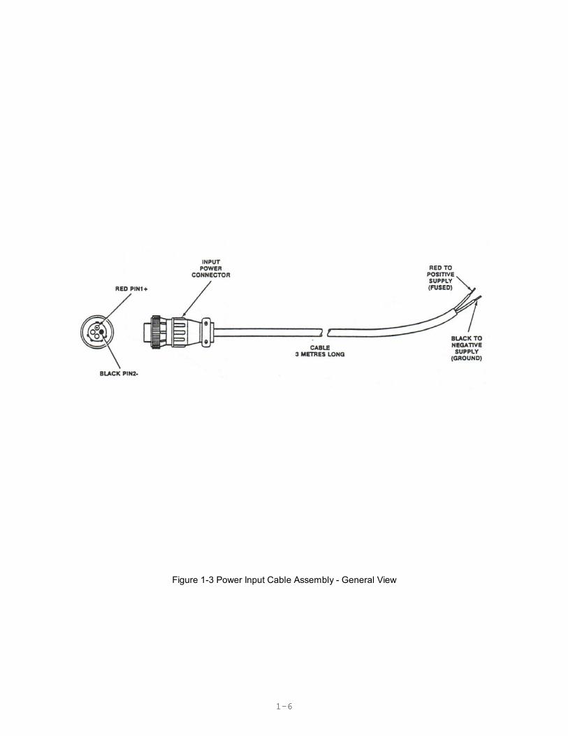
(c) Power Input Cable Assembly, Part Number 863701, is a three-metre length of two-core cable terminated at one end by a two-pin, female contacts, connector, which mateswith the two-pin, male contacts, connector located at the left-rear of the transceiver. Theunterminated end of the cable is connected to the 12Vdc vehicle power supply negative-ground during installation.
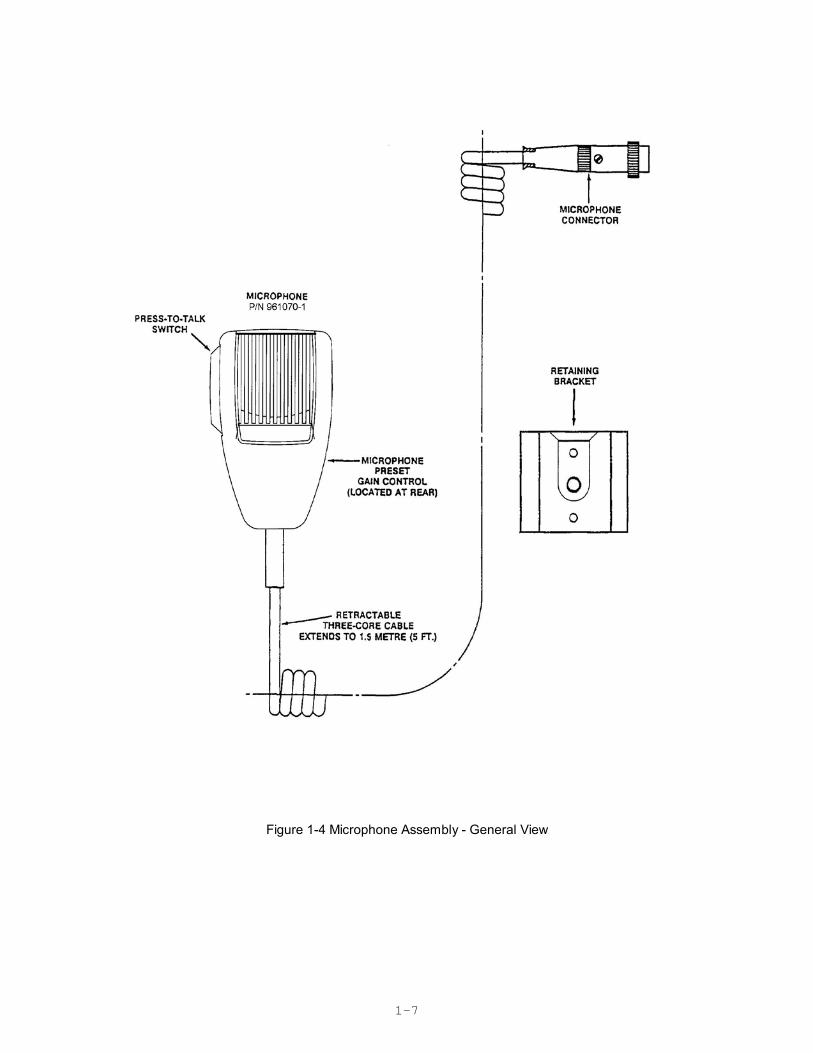
A view of the cable assembly is given in Figure 1-3.(d) Microphone Assembly, Part Number 961070-1, consists of a Microphone and a
mounting bracket, P/N RK6MB.
A general view of the microphone assembly is given in Figure 1-4.
The microphone is a rugged hand-held microphone housed in a high impact plastic casewhich includes a rear case hang-up button for storage on the mounting bracket. Thedynamic microphone is a noise cancelling type with a pre-amplifier, press-to-talk switch, anda retractable three-cord cable terminated by a three-pin male contacts, connector whichmates with the MIC/PTT connector located on the front panel of the transceiver.The microphone dc supply for the microphone is supplied by the transceiver. Themounting bracket, provided with the microphone, should be mounted in a convenientlocation near the transceiver. A small screwdriver which can be used for releasing themodular plug located in the microphone head is supplied with the microphone.
A replacement plug-in microphone cord, P/N 963299-1is available for this microphone. Thiscord is supplied with a modular microphone plug on one end and a three-pin DIN connectoron the other to mate with the Model 90-6R Transceiver.
1-2
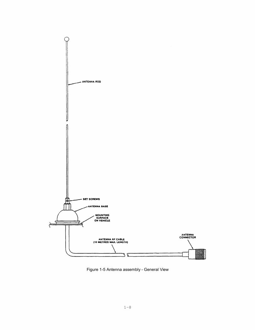
(e) Antenna Assembly, Part Number 861910-1, is supplied complete as a kit which includes the following items: Antenna Base, which includes a mounting pad, together with a pad,braid nut, sleeve and clamp for termination of the antenna RF cable. The Antenna Rod issupplied with an Allen Wrench for adjustment of its set screws. The Antenna RF Cable isa ten-metre length RG58/U coaxial cable terminated at one end by an UHF, male contact,connector which mates with the UHF, female contact, antenna connector located at theright-rear of the transceiver. The antenna may be mounted on any flat surface, roof, cowl,fender or rear deck of a vehicle, however, rooftop mounting is recommended for bestperformance. A general view of the antenna assembly is given in Figure 1-5.
1.1.2 MODES OF OPERATION
The transceiver may be operated in either of two modes; transmit or receive, as selected bythe Press-to-Talk (PTT) switch on the microphone.
(1) TRANSMIT MODE - When the PTT switch on the microphone is pressed, thetransceiver operates in the transmit mode. The PTT signal line is grounded by themicrophone PTT switch via the microphone lead and the MIC/PTT connector to thetransceiver. The Tx ON amber LED will go ON, indicating that the transmitter isactivated.
Transmission will occur on the channel frequency indicated on the front panel. Referto Section 3 for transceiver details
(2) RECEIVE MODE - When the PTT switch on the microphone is released, the transceiver operates in the receive mode. The Tx ON amber LED will go OFF, indicatingthat the transmitter is inhibited. Reception of the frequency displayed on the transceiverwill occur.
1-3
The setting of the SQUELCH CONTROL determines the squelch threshold level. When the SQUELCH CONTROL is rotated in the counter-clockwise direction, theSQUELCH INDICATOR green LED will go ON, indicating that the squelch circuit isconnecting the demodulated audio to the VOLUME CONTROL. The setting of theVOLUME CONTROL determines the audio level produced from the internal speaker.When the VOLUME CONTROL is adjusted in the clockwise direction, the audio level willincrease.
NOTE
When the connector of the external loudspeaker orhead phone is connected to the SPEAKER/PHONEjack, the internal loudspeaker is disconnected and theVOLUME CONTROL will control the audio level of theexternal loudspeaker or headphone.
1-4
Figure 1-1 91-DE Transceiver - General View
1-5
Figure 1-2 91-DE Transceiver with Mounting Bracket
1-6
Figure 1-3 Power Input Cable Assembly - General View
1-7
Figure 1-4 Microphone Assembly - General View
1-8
Figure 1-5 Antenna assembly - General View
1-9
1.2 TECHNICAL SUMMARY
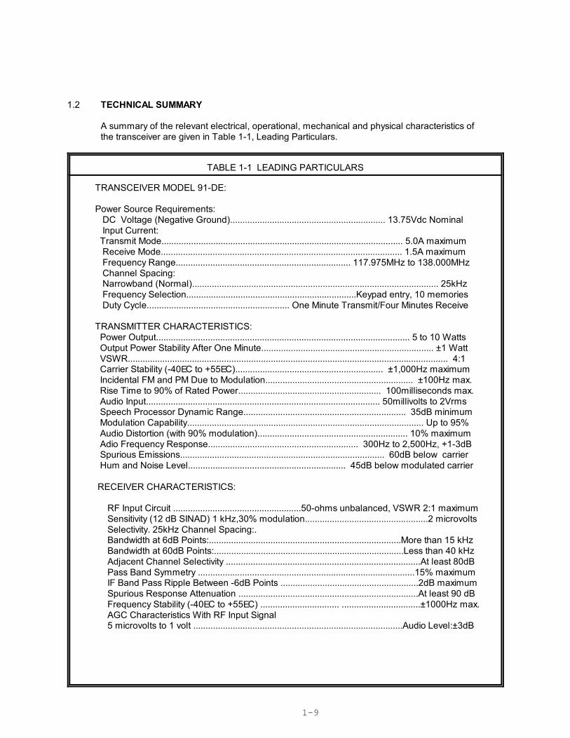
A summary of the relevant electrical, operational, mechanical and physical characteristics of the transceiver are given in Table 1-1, Leading Particulars.
TABLE 1-1 LEADING PARTICULARS
TRANSCEIVER MODEL 91-DE:
Power Source Requirements: DC Voltage (Negative Ground)............................................................... 13.75Vdc Nominal Input Current: Transmit Mode.................................................................................................. 5.0A maximum Receive Mode.................................................................................................. 1.5A maximum Frequency Range....................................................................... 117.975MHz to 138.000MHz Channel Spacing: Narrowband (Normal).................................................................................................... 25kHz Frequency Selection.....................................................................Keypad entry, 10 memories Duty Cycle.......................................................... One Minute Transmit/Four Minutes Receive
TRANSMITTER CHARACTERISTICS: Power Output....................................................................................................... 5 to 10 Watts Output Power Stability After One Minute...................................................................... ±1 Watt VSWR.................................................................................................................................. 4:1 Carrier Stability (-40EC to +55EC)............................................................ ±1,000Hz maximum Incidental FM and PM Due to Modulation............................................................ ±100Hz max. Rise Time to 90% of Rated Power.......................................................... 100milliseconds max. Audio Input............................................................................................... 50millivolts to 2Vrms Speech Processor Dynamic Range.................................................................. 35dB minimum Modulation Capability................................................................................................ Up to 95% Audio Distortion (with 90% modulation)............................................................. 10% maximum Adio Frequency Response............................................................. 300Hz to 2,500Hz, +1-3dB Spurious Emissions................................................................................... 60dB below carrier Hum and Noise Level................................................................ 45dB below modulated carrier
RECEIVER CHARACTERISTICS:
RF Input Circuit ....................................................50-ohms unbalanced, VSWR 2:1 maximum Sensitivity (12 dB SINAD) 1 kHz,30% modulation..................................................2 microvolts Selectivity. 25kHz Channel Spacing:. Bandwidth at 6dB Points:..............................................................................More than 15 kHz Bandwidth at 60dB Points:.............................................................................Less than 40 kHz Adjacent Channel Selectivity ...............................................................................At least 80dB Pass Band Symmetry ........................................................................................15% maximum IF Band Pass Ripple Between -6dB Points ........................................................2dB maximum Spurious Response Attenuation .........................................................................At least 90 dB Frequency Stability (-40EC to +55EC) ................................ ................................±1000Hz max. AGC Characteristics With RF Input Signal 5 microvolts to 1 volt .....................................................................................Audio Level:±3dB
1-9
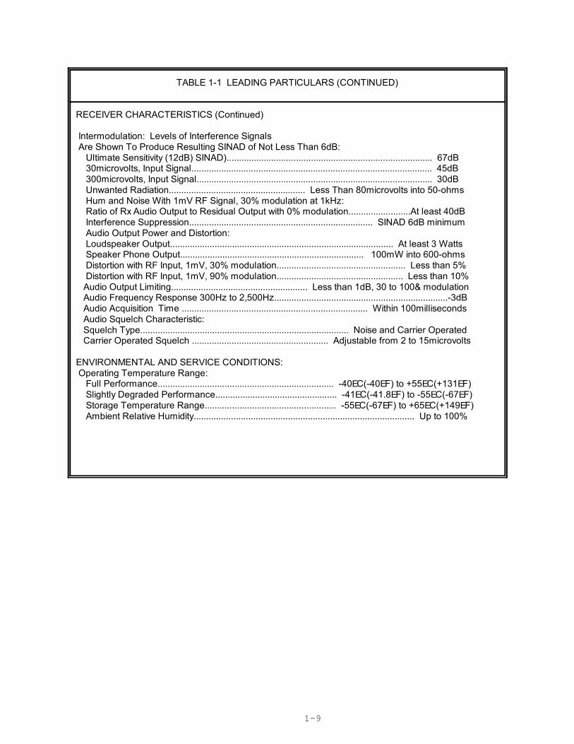
TABLE 1-1 LEADING PARTICULARS (CONTINUED)
RECEIVER CHARACTERISTICS (Continued)
Intermodulation: Levels of Interference Signals Are Shown To Produce Resulting SINAD of Not Less Than 6dB: Ultimate Sensitivity (12dB) SINAD)................................................................................... 67dB 30microvolts, Input Signal................................................................................................. 45dB 300microvolts, Input Signal............................................................................................... 30dB Unwanted Radiation....................................................... Less Than 80microvolts into 50-ohms Hum and Noise With 1mV RF Signal, 30% modulation at 1kHz: Ratio of Rx Audio Output to Residual Output with 0% modulation.........................At least 40dB Interference Suppression.......................................................................... SINAD 6dB minimum Audio Output Power and Distortion: Loudspeaker Output.......................................................................................... At least 3 Watts Speaker Phone Output.......................................................................... 100mW into 600-ohms Distortion with RF Input, 1mV, 30% modulation.................................................... Less than 5% Distortion with RF Input, 1mV, 90% modulation................................................... Less than 10% Audio Output Limiting....................................................... Less than 1dB, 30 to 100& modulation Audio Frequency Response 300Hz to 2,500Hz......................................................................-3dB Audio Acquisition Time ........................................................................... Within 100milliseconds Audio Squelch Characteristic: Squelch Type.................................................................................... Noise and Carrier Operated Carrier Operated Squelch ....................................................... Adjustable from 2 to 15microvolts ENVIRONMENTAL AND SERVICE CONDITIONS: Operating Temperature Range: Full Performance....................................................................... -40EC(-40EF) to +55EC(+131EF) Slightly Degraded Performance................................................. -41EC(-41.8EF) to -55EC(-67EF) Storage Temperature Range..................................................... -55EC(-67EF) to +65EC(+149EF) Ambient Relative Humidity......................................................................................... Up to 100%
2-1
SECTION 2
INSTALLATION INFORMATION
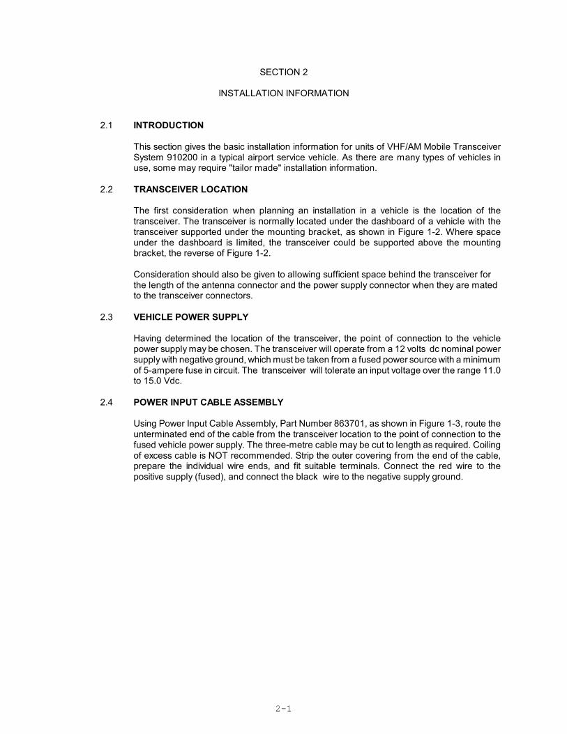
2.1 INTRODUCTION
This section gives the basic installation information for units of VHF/AM Mobile TransceiverSystem 910200 in a typical airport service vehicle. As there are many types of vehicles inuse, some may require "tailor made" installation information.
2.2 TRANSCEIVER LOCATION
The first consideration when planning an installation in a vehicle is the location of thetransceiver. The transceiver is normally located under the dashboard of a vehicle with thetransceiver supported under the mounting bracket, as shown in Figure 1-2. Where spaceunder the dashboard is limited, the transceiver could be supported above the mountingbracket, the reverse of Figure 1-2.
Consideration should also be given to allowing sufficient space behind the transceiver forthe length of the antenna connector and the power supply connector when they are matedto the transceiver connectors.
2.3 VEHICLE POWER SUPPLY
Having determined the location of the transceiver, the point of connection to the vehiclepower supply may be chosen. The transceiver will operate from a 12 volts dc nominal powersupply with negative ground, which must be taken from a fused power source with a minimumof 5-ampere fuse in circuit. The transceiver will tolerate an input voltage over the range 11.0to 15.0 Vdc.
2.4 POWER INPUT CABLE ASSEMBLY
Using Power Input Cable Assembly, Part Number 863701, as shown in Figure 1-3, route theunterminated end of the cable from the transceiver location to the point of connection to thefused vehicle power supply. The three-metre cable may be cut to length as required. Coilingof excess cable is NOT recommended. Strip the outer covering from the end of the cable,prepare the individual wire ends, and fit suitable terminals. Connect the red wire to thepositive supply (fused), and connect the black wire to the negative supply ground.
2-2
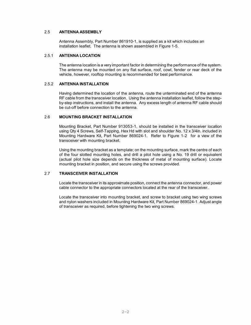
2.5 ANTENNA ASSEMBLY
Antenna Assembly, Part Number 861910-1, is supplied as a kit which includes aninstallation leaflet. The antenna is shown assembled in Figure 1-5.
2.5.1 ANTENNA LOCATION
The antenna location is a very important factor in determining the performance of the system.The antenna may be mounted on any flat surface, roof, cowl, fender or rear deck of thevehicle, however, rooftop mounting is recommended for best performance.
2.5.2 ANTENNA INSTALLATION
Having determined the location of the antenna, route the unterminated end of the antennaRF cable from the transceiver location. Using the antenna installation leaflet, follow the step-by-step instructions, and install the antenna. Any excess length of antenna RF cable shouldbe cut-off before connection to the antenna.
2.6 MOUNTING BRACKET INSTALLATION
Mounting Bracket, Part Number 913053-1, should be installed in the transceiver locationusing Qty 4 Screws, Self-Tapping, Hex Hd with slot and shoulder No. 12 x 3/4in. included inMounting Hardware Kit, Part Number 869024-1. Refer to Figure 1-2 for a view of thetransceiver with mounting bracket.
Using the mounting bracket as a template; on the mounting surface, mark the centre of eachof the four slotted mounting holes, and drill a pilot hole using a No. 19 drill or equivalent(actual pilot hole size depends on the thickness of metal of mounting surface). Locatemounting bracket in position, and secure using the screws provided.
2.7 TRANSCEIVER INSTALLATION
Locate the transceiver in its approximate position, connect the antenna connector, and powercable connector to the appropriate connectors located at the rear of the transceiver.
Locate the transceiver into mounting bracket, and screw to bracket using two wing screwsand nylon washers included in Mounting Hardware Kit, Part Number 869024-1. Adjust angleof transceiver as required, before tightening the two wing screws.
2-3
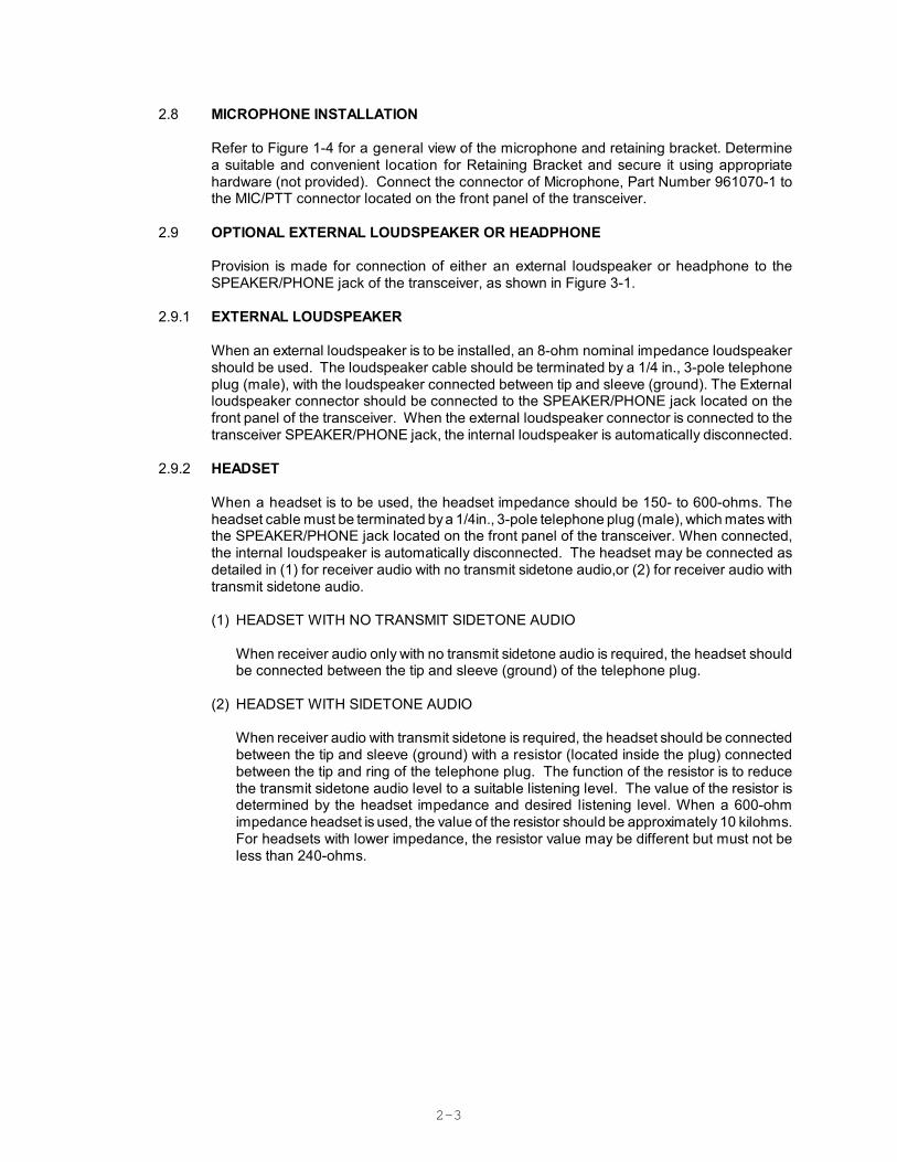
2.8 MICROPHONE INSTALLATION
Refer to Figure 1-4 for a general view of the microphone and retaining bracket. Determinea suitable and convenient location for Retaining Bracket and secure it using appropriatehardware (not provided). Connect the connector of Microphone, Part Number 961070-1 tothe MIC/PTT connector located on the front panel of the transceiver.
2.9 OPTIONAL EXTERNAL LOUDSPEAKER OR HEADPHONE
Provision is made for connection of either an external loudspeaker or headphone to theSPEAKER/PHONE jack of the transceiver, as shown in Figure 3-1.
2.9.1 EXTERNAL LOUDSPEAKER
When an external loudspeaker is to be installed, an 8-ohm nominal impedance loudspeakershould be used. The loudspeaker cable should be terminated by a 1/4 in., 3-pole telephoneplug (male), with the loudspeaker connected between tip and sleeve (ground). The Externalloudspeaker connector should be connected to the SPEAKER/PHONE jack located on thefront panel of the transceiver. When the external loudspeaker connector is connected to thetransceiver SPEAKER/PHONE jack, the internal loudspeaker is automatically disconnected.
2.9.2 HEADSET
When a headset is to be used, the headset impedance should be 150- to 600-ohms. Theheadset cable must be terminated by a 1/4in., 3-pole telephone plug (male), which mates withthe SPEAKER/PHONE jack located on the front panel of the transceiver. When connected,the internal loudspeaker is automatically disconnected. The headset may be connected asdetailed in (1) for receiver audio with no transmit sidetone audio,or (2) for receiver audio withtransmit sidetone audio.
(1) HEADSET WITH NO TRANSMIT SIDETONE AUDIO
When receiver audio only with no transmit sidetone audio is required, the headset shouldbe connected between the tip and sleeve (ground) of the telephone plug.
(2) HEADSET WITH SIDETONE AUDIO
When receiver audio with transmit sidetone is required, the headset should be connectedbetween the tip and sleeve (ground) with a resistor (located inside the plug) connectedbetween the tip and ring of the telephone plug. The function of the resistor is to reducethe transmit sidetone audio level to a suitable listening level. The value of the resistor isdetermined by the headset impedance and desired listening level. When a 600-ohmimpedance headset is used, the value of the resistor should be approximately 10 kilohms.For headsets with lower impedance, the resistor value may be different but must not beless than 240-ohms.

2-4
2.10 OPERATIONAL CHECK
Perform an operational check of the transceiver, checking each channel in use in both thetransmit and receive modes of operation, using the Operating instructions given in Section3 of this document and the appropriate specified operating procedures during transmission.
3-1
SECTION 3
OPERATING INSTRUCTIONS
3.1 INTRODUCTION
3.1.1 Transceiver Model TiL-91-DE P/N 901006-2
The Transceiver is a microprocessor controlled VHF/AM transceiver operating over the entire bandof 117.975 to 138.000 MHz in 25 KHz steps. The transceiver will store ten user selected frequencychannels in addition to the resident emergency channel of 121.500 MHz. Frequency Selection,Storage, Recall, Channel Scan, Search, and Toggle modes are all selected by the 12 key keypad.The current operating frequency is displayed on a backlit liquid crystal display (LCD).
3.1.2 Scan, Search, and Toggle Modes
1. SCAN MODE - In Scan Mode, the transceiver cycles through the preset Channel Frequencies and locks on to the first channel received in scan sequence. Audio is enabled for 5 seconds foroperator identification. Pressing the Press-to-Talk switch exits the scan mode. If there is nooperator action then transceiver operates in the scan sequence continuously.
2. SEARCH MODE - In Search mode the transceiver cycles through the preset Channel Frequencies and locks on to the first channel received in the scan sequence and normal operation is resumed.
3. TOGGLE MODE - In toggle mode the transceiver alternates between the current channel selection and the previous channel selected.
This section includes a functional description of each switch, control, indicator and connectorlocated on the front and rear panels of the 91-DE mobile transceiver, including thePRESS-TO-TALK switch located on the microphone. Operating instructions for transmit/receiveand the special functions are also included.
3.1.3 Technical Summary
A summary of electrical, operational, mechanical and physical characteristics of the transceiver, isprovided in Table 3-1.
3.2 OPERATOR'S SWITCHES, CONTROLS AND INDICATORS
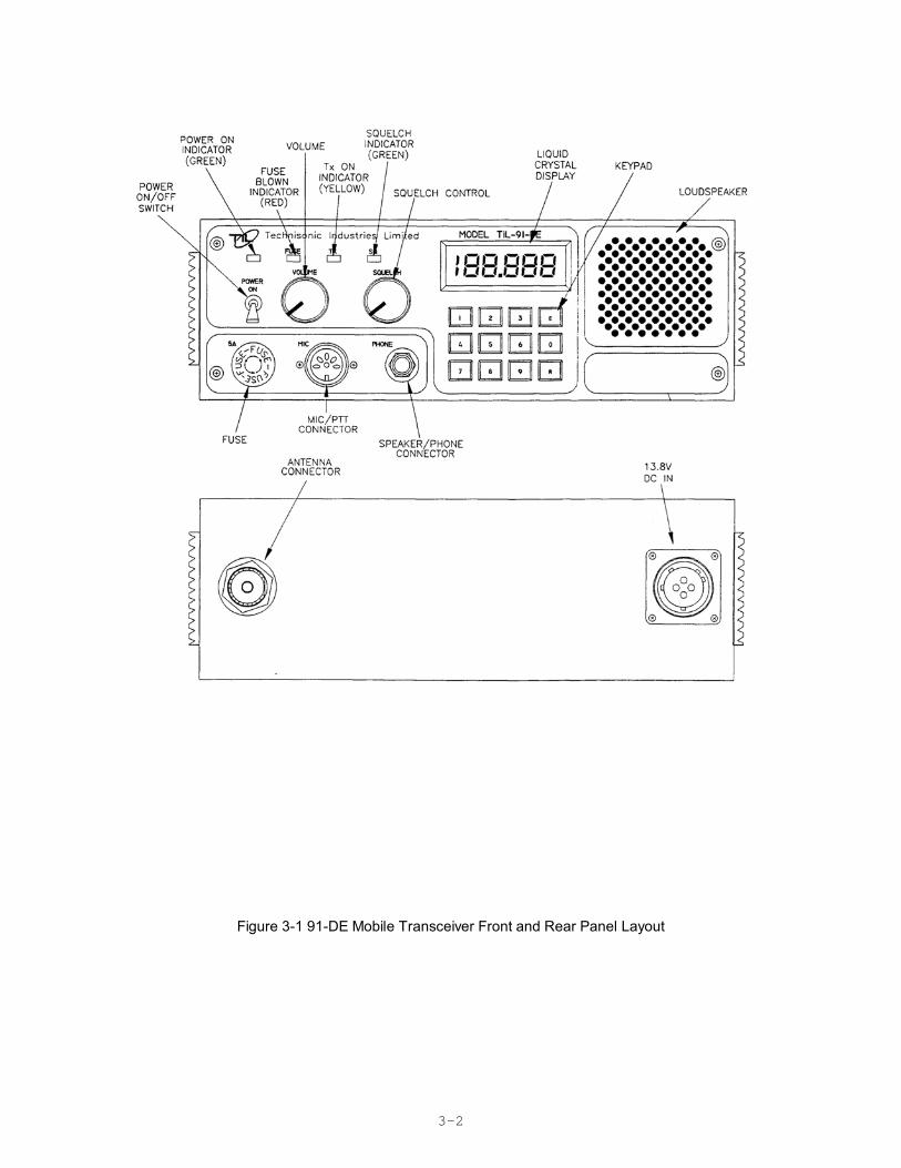
A view of the front and rear panels of the 91-DE Transceiver is given in Figure 3-1. A functionaldescription of each of the operator's switches, controls and indicators, and the microphonePRESS-TO-TALK switch, is given in Table 3-1, Operator's Switches, Controls and Indicators and inTable 3-2, Channel/Function Selector Keypad.
3-2
Figure 3-1 91-DE Mobile Transceiver Front and Rear Panel Layout
3-3
TABLE 3-1 OPERATORS SWITCHES, CONTROLS AND INDICATORS
No.SWITCHES
CONTROLS &INDICATORS
FUNCTIONAL DESCRIPTION
1 POWERON/OFFSWITCH
A toggle switch applies the 13.7 volts nominal power supply to thetransceiver. The transceiver is switched to ON in the toggle UP position andis switched OFF in the toggle DOWN position.
2 POWER ONLEDINDICATOR
A GREEN LED indicates when the POWER ON/OFF switch is set to ONand voltage is applied to the transceiver.
3 FUSE A 5 Amp FUSE protects the 13.7 volts dc nominal power supply line.
4 FUSE BLOWNRED LEDINDICATOR
A RED LED indicates when the 5-Amp fuse is "blown", and External DCBattery or AC power is present.
5 SQUELCHCONTROL
A linear potentiometer determines the squelch threshold level. When theSQUELCH CONTROL is rotated in the counter-clockwise direction, theSQUELCH GREEN LED indicates that the squelch is connectingdemodulated audio to the VOLUME control.
6 SQUELCHINDICATOR GREEN LED
A GREEN LED indicates the squelch circuit is connecting demodulated audiosignal to the VOLUME control.
7 Tx ON AMBER LEDINDICATOR
An AMBER LED indicates when the transceiver is keyed by the microphonePRESS-TO-TALK (PTT) switch or remote land line, and the transceiver isoperated in the Tx mode. The Tx ON AMBER LED switches OFF, when thetransceiver is operated in the receive mode.
8 VOLUMECONTROL
A logarithmic potentiometer determines the audio level applied to the internalspeaker when the transceiver is operated in the receive mode. When theSPEAKER/PHONE connector is in use the internal loudspeaker isdisconnected and the VOLUME CONTROL sets the audio level applied to theexternal speaker or headphone.
9 MIC/PTTCONNECTOR
A 5-pin connector functions as Microphone/PTT and Test Connector.Pin 1 - PTT Signal LinePin 2 - Microphone Signal GroundPin 3 - Microphone Signal and Microphone DC Supply LinePin 4 - AGC test voltagePin 5 - Squelch test voltage
10 MICROPHONEPTT
PRESS-TO-TALK (PTT) switch determines transceiver operating mode.When the PTT switch is pressed, the transceiver operates in Tx mode. Whenthe PTT switch is released, the transceiver operates in Rx mode.
11 KEYPAD Performs Chan/Freq and Special Feature Selection (Refer Table 3-2).
3-4
TABLE 3-1 OPERATORS SWITCHES, CONTROLS AND INDICATORS (Continued)
FIG3-1No.
SWITCHESCONTROLS &INDICATORS
FUNCTIONAL DESCRIPTION
12 LIQUIDCRYSTALDISPLAY
A 5½ digit Liquid Crystal Display (LCD) displays the FREQUENCY/CHANNEL that the transceiver is currently operating on. In SCAN mode itdisplays the current frequency scanned if RF signal is present.
13 LOUDSPEAKER An 8-ohm internal speaker reproduces the receiver audio output. The audioline is disconnected from the internal loudspeaker when the transceiver isoperated in Tx mode or when the SPEAKER/PHONE connector is in use.
14 SPEAKER/PHONECONNECTOR
A 3-pole connector provides interconnection to either an externalloudspeaker or headphone. When in use, the internal speaker isdisconnected and the VOLUME control sets the audio level applied to theexternal speaker or headphone.
3-5
3.3 FRONT PANEL KEYPAD OPERATION
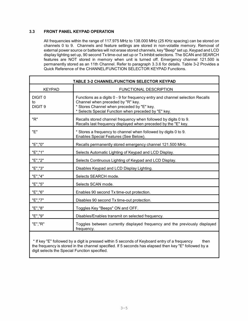
All frequencies within the range of 117.975 MHz to 138.000 MHz (25 KHz spacing) can be stored onchannels 0 to 9. Channels and feature settings are stored in non-volatile memory. Removal ofexternal power source or batteries will not erase stored channels, key "Beep" set up, Keypad and LCDdisplay lighting set up, 90 second Tx time-out set up or Tx Inhibit selections. The SCAN and SEARCHfeatures are NOT stored in memory when unit is turned off. Emergency channel 121.500 ispermanently stored as an 11th Channel. Refer to paragraph 3.3.6 for details. Table 3-2 Provides aQuick Reference of the CHANNEL/FUNCTION SELECTOR KEYPAD Functions.
TABLE 3-2 CHANNEL/FUNCTION SELECTOR KEYPAD
KEYPAD FUNCTIONAL DESCRIPTION
DIGIT 0toDIGIT 9
Functions as a digits 0 - 9 for frequency entry and channel selection RecallsChannel when preceded by "R" key. * Stores Channel when preceded by "E" key.* Selects Special Function when preceded by "E" key.
"R" Recalls stored channel frequency when followed by digits 0 to 9. Recalls last frequency displayed when preceded by the "E" key.
"E" * Stores a frequency to channel when followed by digits 0 to 9. Enables Special Features (See Below).
"E","0" Recalls permanently stored emergency channel 121.500 MHz.
"E","1" Selects Automatic Lighting of Keypad and LCD Display.
"E","2" Selects Continuous Lighting of Keypad and LCD Display.
"E","3" Disables Keypad and LCD Display Lighting.
"E","4" Selects SEARCH mode.
"E","5" Selects SCAN mode.
"E","6" Enables 90 second Tx time-out protection.
"E","7" Disables 90 second Tx time-out protection.
"E","8" Toggles Key "Beeps" ON and OFF.
"E","9" Disables/Enables transmit on selected frequency.
"E","R" Toggles between currently displayed frequency and the previously displayedfrequency.
* If key "E" followed by a digit is pressed within 5 seconds of Keyboard entry of a frequency thenthe frequency is stored in the channel specified. If 5 seconds has elapsed then key "E" followed by adigit selects the Special Function specified.
3-6
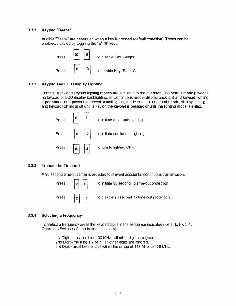
3.3.1 Keypad "Beeps"
Audible "Beeps" are generated when a key is pressed (default condition). Tones can be enabled/disabled by toggling the "E","8" keys.
Press to disable Key "Beeps".
Press to enable Key "Beeps".
3.3.2 Keypad and LCD Display Lighting
Three Display and keypad lighting modes are available to the operator. The default mode providesno keypad or LCD display backlighting. In Continuous mode, display backlight and keypad lightingis permanent until power is removed or until lighting mode exited. In automatic mode, display backlightand keypad lighting is off until a key on the keypad is pressed or until the lighting mode is exited.
Press to initiate automatic lighting.
Press to initiate continuous lighting.
Press to turn to lighting OFF.
3.3.3 Transmitter Time-out
A 90 second time-out timer is provided to prevent accidental continuous transmission.
Press to initiate 90 second Tx time-out protection.
Press to disable 90 second Tx time-out protection.
3.3.4 Selecting a Frequency
To Select a frequency press the keypad digits in the sequence indicated (Refer to Fig 3-1,Operators Switches Controls and Indicators).
1st Digit - must be 1 for 100 MHz, all other digits are ignored.2nd Digit - must be 1,2 or 3, all other digits are ignored.3rd Digit - must be any digit within the range of 117 MHz to 138 MHz.
3-7
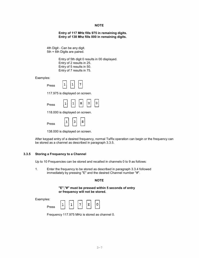
NOTE
Entry of 117 MHz fills 975 in remaining digits.Entry of 138 Mhz fills 000 in remaining digits.
4th Digit - Can be any digit.5th + 6th Digits are paired.
Entry of 5th digit 0 results in 00 displayed.Entry of 2 results in 25. Entry of 5 results in 50. Entry of 7 results in 75.
Examples: Press
117.975 is displayed on screen.
Press
118.000 is displayed on screen.
Press
138.000 is displayed on screen.
After keypad entry of a desired frequency, normal Tx/Rx operation can begin or the frequency canbe stored as a channel as described in paragraph 3.3.5.
3.3.5 Storing a Frequency to a Channel
Up to 10 Frequencies can be stored and recalled in channels 0 to 9 as follows:
1. Enter the frequency to be stored as described in paragraph 3.3.4 followed immediately by pressing "E" and the desired Channel number "#".
NOTE
"E","#" must be pressed within 5 seconds of entryor frequency will not be stored.
Examples: Press
Frequency 117.975 MHz is stored as channel 0.
3-8
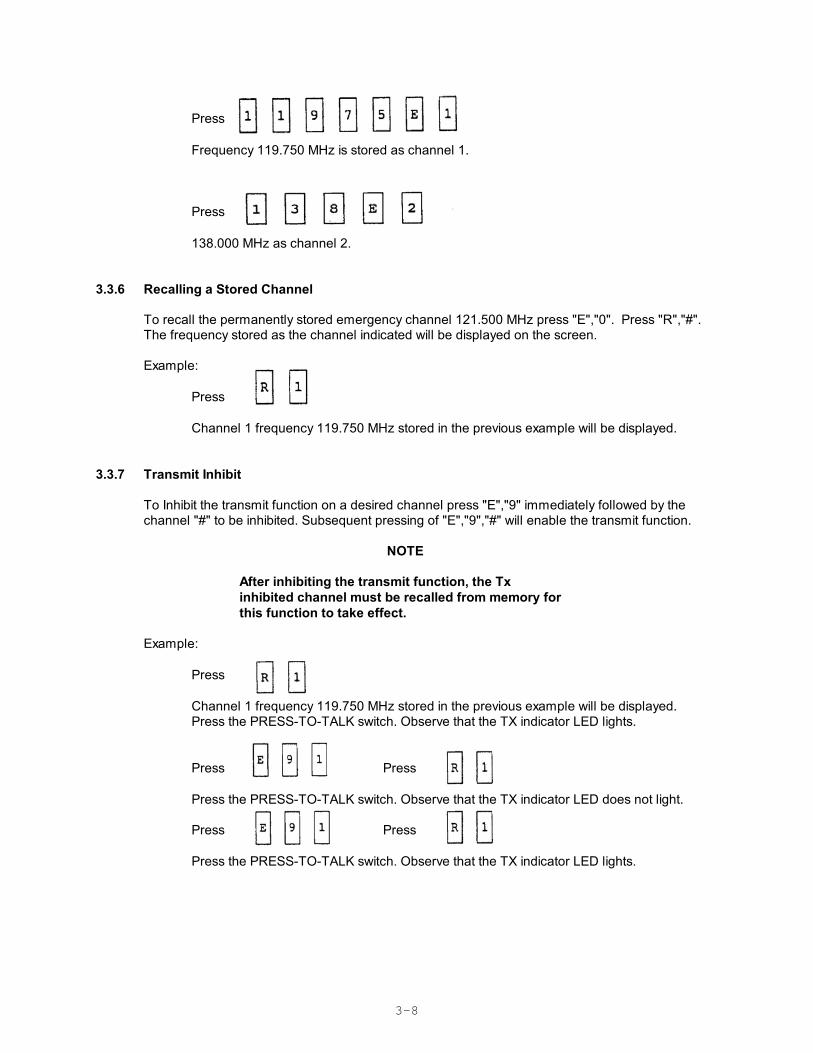
Press
Frequency 119.750 MHz is stored as channel 1.
Press
138.000 MHz as channel 2.
3.3.6 Recalling a Stored Channel
To recall the permanently stored emergency channel 121.500 MHz press "E","0". Press "R","#".The frequency stored as the channel indicated will be displayed on the screen.
Example: Press
Channel 1 frequency 119.750 MHz stored in the previous example will be displayed.
3.3.7 Transmit Inhibit
To Inhibit the transmit function on a desired channel press "E","9" immediately followed by thechannel "#" to be inhibited. Subsequent pressing of "E","9","#" will enable the transmit function.
NOTE
After inhibiting the transmit function, the Txinhibited channel must be recalled from memory forthis function to take effect.
Example: Press
Channel 1 frequency 119.750 MHz stored in the previous example will be displayed.Press the PRESS-TO-TALK switch. Observe that the TX indicator LED lights.
Press Press
Press the PRESS-TO-TALK switch. Observe that the TX indicator LED does not light.
Press Press
Press the PRESS-TO-TALK switch. Observe that the TX indicator LED lights.
3-9
3.3.8 Toggling Between Two Channels
Press to recall previous channel.
Example:
Recall Channel 0 as described in para 4.3.6117.975 will be displayed.
Recall Channel 2 138.000 will be displayed.
Press
117.975 will be displayed.
Press
138.000 will be displayed.
3.3.9 Search Mode
In SEARCH MODE the receiver steps through each stored channel until a transmitted signal is found.The receiver will lock on to the first signal strong enough to quiet the squelch circuit. SEARCH modeis exited when a signal is found. Normal operation resumes as if the SEARCH frequency was selectedfrom the keypad or recalled from memory.
Press to enter SEARCH mode.
Press to exit SEARCH mode.
3.3.10 Scan Mode
In SCAN MODE the receiver steps through each stored channel until a transmitted signal is found. The receiver will lock on to the first signal strong enough to quiet the squelch circuit. When asignal is found, the frequency is displayed and the audio is enabled for as long as the squelch is heldopen by the RF signal. After the signal drops below the squelch threshold SCAN is resumed until thenext frequency is found and the process is repeated. SCAN mode is continuous until the operator exitsor the unit is switched off.
3-10
NOTE
PTT is inhibited during SCAN mode.Pressing PTT once exits SCAN mode.Pressing PTT twice is required to Key theTransmitter.
Press to enter SCAN mode.
Press PTT to Lock on SCANned Frequency or
Press to exit SCAN.
3-11
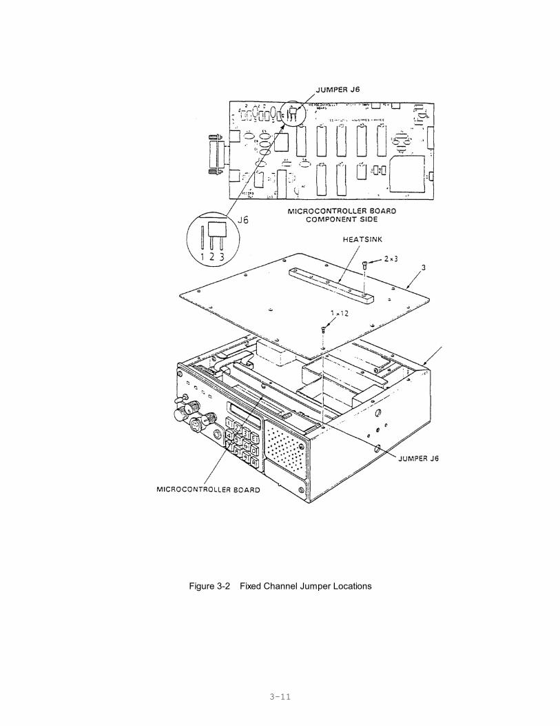
Figure 3-2 Fixed Channel Jumper Locations
3-12
3.4 FIXED CHANNEL FREQUENCY SET UP
The following procedure fixes preselected channel frequencies and inhibits transmit on receiveonly channels. After completion of this procedure the operator will be able select stored channels only for receive or transmit. Keypad entry of frequencies is disabled.
3.4.1 System Configuration
(1) Configure channel frequencies as desired (Refer to Section 3.3.5).
(2) Select channels for Rx only (transmit inhibit) operation (Refer to paragraph 3.3.7).
3.4.2 Transceiver Disassembly/Assembly and Jumper Installation
(1) Refer to Section 2 for Transceiver installation and removal procedures.
(2) Remove and retain 15 flathead screws (1) securing transceiver top cover (3) to chassis (4). Refer to Figure 3-2.
(3) Position Jumper J6 on pin 1 and pin 2 to disable keyboard entry of frequency selection and lock operating configuration.
(4) Position Jumper J6 on pin 2 and pin 3 to enable keypad frequency selection and unlock operating configuration.
(5) Position Transceiver Cover (3) on Chassis (4). Ensure that cover holes are aligned with threaded inserts.
(6) Position 15 flathead screws (1) and through cover (3) holes into chassis (4) threaded inserts. Tighten screws with fingers.
(7) Tighten screws securing Transceiver Cover (3) to Chassis (4).
(8) Refer to section 2 for Transceiver installation and removal procedures.
3.4.3 Operational Check
(1) Turn Unit On (Refer to paragraph 3.2).
(2) Recall Channels "0" through "9" (Refer to paragraph 3.3.6). Ensure that the frequencies indicated for each channel displayed correspond to those selected.
(3) Transmit on each channel. Observe that the TX Led (Refer to Figure 3-1, for location) does not light on channels selected to operate exclusively in receive mode.
(4) Enter a valid frequency (within the frequency range of (117.975 MHz to 138 MHz) that differs from the frequency stored in channel "0".
(5) Store the frequency in channel "0" (Refer to paragraph 3.3.5).

3-13
(6) Recall Channel "0" frequency. Channel "0" frequency displayed shall be the samefrequency entered before Locking the operating configuration (ie. different from thefrequency entered in step 4).
(7) Perform Steps 4 through 6 for each channel.


![IN1140: Introduksjon til språkteknologi [3ex] Forelesning #3 · INF1140: Introduksjon til språkteknologi IN1140: Introduksjon til språkteknologi Forelesning #3 LiljaØvrelid Universitetet](https://img.pdfslide.us/doc/110x75/600f3ff115e91631e65635c1/in1140-introduksjon-til-sprkteknologi-3ex-forelesning-3-inf1140-introduksjon.jpg)


![Immune Suppression in Tumors as a Surmountable Obstacle to ... · Clark, 1989 [31] 386 TIL absent 59 e TIL brisk 89 TIL non-brisk 75 + - Clemente, 1996 [35] 285 TIL absent 37 TIL](https://img.pdfslide.us/doc/110x75/5c8ad5c409d3f2016f8b7582/immune-suppression-in-tumors-as-a-surmountable-obstacle-to-clark-1989-31.jpg)