Embed Size (px)
Citation preview
SY.TRA.MA Srl
EMAN 91a Issue date: 04/11/98 Revision index: 00 Page 1 of 76
CODE: EMAN 91 a
USER AND MAINTENANCE MANUALMODEL : 91 E2-E3
MACHINE SERIAL NO.:YEAR OF CONSTRUCTION:
SY.TRA.MA SRLVia Lombardia , 30
20060 Vignate (MI)-ITALY

SY.TRA.MA Srl
EMAN 91a Issue date: 04/11/98 Revision index: 00 Page 2 of 76
Dear Customer,
we thank you for your trusting in our Company.
We are hereby supplying you with this manual EMAN 91a that has to be considered as anintegral part of the machine you have bought.
Let us remind you that this manual can’t be duplicated or reproduced or distributed to thirdparties unless duly authorized by us.
Feeling confident that we have deserved your trust please arrange for the proper diffusionof this manual according to the aims it contains.
SY.TRA.MA SRL
SY.TRA.MA Srl
EMAN 91a Issue date: 04/11/98 Revision index: 00 Page 3 of 76
INDEX
1. PRELIMINARY INFORMATION Page 6- contents of the manual Page 6- who should use this manual Page 6- key to the rapid consultation of the manual Page 6- updating of the manual Page 7- legend for graphic symbols used on the machine Page 7- maintaining the plates in a legible condition Page 8- conformity with Directives - declarations Page 9- responsibility Page 9- guarantee of the constructor Page 9
2. THE RSV 91 MODEL ROBOTS Page 10- introduction Page 10- performance and operating characteristics (intended use) Page 11- estimated use Page 11- not estimated use Page 11- what always to do Page 11- what never to do Page 13- limits regarding the direction of the movements of the axes Page 14- dimensions and technical characteristics Page 15- packing and transport Page 18
3. INSTALLATION INSTRUCTIONS Page 18
3.1 PRE-INSTALLATION OPERATIONS Page 18- preparation of the area Page 18- drilling the fixed platen of the injection moulding machine Page 19- interfacing the robot with the moulding machine according to
the Euromap 12 regulations Page 20- preparing the electrical connections Page 26- preparing the connections to the compressed air system Page 26- loading the appropriate mould onto the injection moulding machine Page 26- preparing the gripper Page 26- preparing the hoisting means Page 26
3.2 INSTALLATION OF THE ROBOT Page 27- hoisting and fixing the support frame Page 27- chart of the torsion values for blocking class 8.8 bolts Page 28- hoisting and fixing the robot Page 29- installation of the safety guards Page 31- positioning the control panel Page 32- completing the interconnections between
panel/robot/interface/push button control panel Page 32- connecting to the main power supply Page 32- parts composing the pneumatic and vacuum system Page 33
3.3 IDENTIFICATION OF THE CONTROL UNIT Page 34- description of the control panel Page 34- identification of the external devices attached to the control panel Page 35- operating and control key board type TME Page 36
SY.TRA.MA Srl
EMAN 91a Issue date: 04/11/98 Revision index: 00 Page 4 of 76
4. OPERATING INSTRUCTIONS Page 38
4.1 PUTTING THE ROBOT INTO OPERATION Page 38- preliminary checks Page 38- adjusting settings and testing the operations Page 38- operating efficiency Page 38- lighting Page 38
4.2 TROUBLE SHOOTING DRIVE DIAGNOSIS Page 39- introduction Page 39- encoder phasing for PHASE drive Page 39- front view of the PHASE drive Page 40- trouble shooting for PHASE drive Page 41- diagnostic for PHASE drive Page 43
4.3 OTHER OPERATIONS Page 44- tool changes: substitution of the gripper Page 44- preparing the robot for a period of inactivity Page 44- drawing for pneumatic connection of the gripper Page 45- storing the robot Page 46- start up after storage period Page 46
- 5. MAINTENANCE INSTRUCTIONS Page 47
5.1 MAINTENANCE Page 47
5.2 PARTICULAR UNPLANNED MAINTENANCE OPERATIONS Page 47- procedure for changing the batteries Page 47
5.3 ROUTINE MAINTENANCE Page 51- daily operations to be performed by the operator Page 51- weekly operations to be performed by the operator and/or specialized
maintenance staff Page 51
5.4 PLANNED PERIODIC MAINTENANCE Page 51- checking the pressure switch setting Page 53- checking the pressure regulator Page 53- checking the vacuum switch setting Page 54- checking the translation bars of the axis Page 55- checking the gear reduction units Page 55- checking the toothed belts Page 55- checking the scroll- worm screw of X axis Page 55- checking the cylinders Page 55- checking the lubrication of bars and sliding blocks Page 56- checking the tightness of the bolts Page 56- checking the leads, connections, cables, push buttons and the electricalsafety devices Page 56
- planned maintenance timetable Page 57
5.5 DISMOUNTING THE ROBOT Page 58- procedure for dismounting the robot Page 58
5.6 SCRAPPING AND DISPOSAL Page 58
SY.TRA.MA Srl
EMAN 91a Issue date: 04/11/98 Revision index: 00 Page 5 of 76
6. SPARE PARTS Page 59
6.1 IDENTIFYING SPARE PARTS PAGES FOR MODELS 91 E-2, E-3 Page 59
6.2 RECOMMENDED SPARE PARTS FOR MODEL 91 E2,E-3 Page 74
7. REGISTER OF THE QUARTERLY AND ANNUAL MAINTENANCE OPERATIONSAND OF THE CONTROLS, ADJUSTMENTS AND PART REPLACEMENTS Page 75
8. ERRATA CORRIGE OR PAGE INTENTIONALLY EMPTY Page 76
SY.TRA.MA Srl
EMAN 91a Issue date: 04/11/98 Revision index: 00 Page 6 of 76
1.PRELIMINARY INFORMATION
CONTENTS OF THE MANUAL
This manual contains the descriptions of the robots belonging to the model RSV 91 E2, E3, and their
“intended use”, their technical characteristics in terms of their functions and performance, instructions for theinstallation, use and maintenance of the versions indicated.
The following documents are supplied as an integral part of the manual: declaration of conformity CE according to 89/392 CEE Directive-annexe II A declaration of the manufacturer according to 89/392 CEE Directive annexe II B
The machines are supplied complete with:
- electrical wiring diagrams- diagrams of the pneumatic system- sketch of the safety guards, if part of the supply- programming manual- user and maintenance manual (this document)
WHO SHOULD USE THIS MANUAL?
This manual should be consulted by:- the Production or Factory Manager, Department Manager or Supervisor- all personnel authorised to use the equipment who has been specifically trained by our installation staff- the machine operator- all maintenance personnelNOTE: it will have to be released to the Safety Representative of personnel- each section of the manual contains an indication of the jobholder to whom it is addressed
The Manual must be kept in an appropriate place, under the responsibility of a specifically designatedperson, to ensure that it is permanently available for consultation and is maintained in perfect condition.
In case of loss or deterioration the substitution must be requested directly from:
SY.TRA.MA SRL , Via Lombardia, 30 20060 Vignate (MI) ITALYTel: 02/9593981 Fax: 9560114
quoting the serial number on the riveted plate on the robot.
KEY TO THE RAPID CONSULTATION OF THE MANUAL
The instructions contained in the manual are accompanied by symbols which facilitate the consultationindicating the different types of information supplied as detailed below:
SY.TRA.MA Srl
EMAN 91a Issue date: 04/11/98 Revision index: 00 Page 7 of 76
INDICATION OF ABSOLUTE NECESSITY
Pay the maximum attention to the instructions accompanied by this symbol and followscrupulously the indications given.
IMPORTANT INFORMATION
Indicates that the information and advice given is useful and relates to the operations of transport,assembly, installation, use and maintenance.
indicates the operating sequence to be followed
The following information and instructions can be found attached directly to machine:
- plate bearing CE mark;- name plate showing: year of construction and serial number; voltage rating, frequency and maximuminstalled power consumption- indications relating to the use and control of the machine (e.g. arrows indicating the direction of movement
of the axes)
IT IS OBLIGATORY TO ENSURE THAT ALL THE VARIOUS SECTIONS OF THIS MANUAL HAVE BEENREAD BY THE APPROPRIATE PERSONNEL BEFORE PROCEEDING TO ANY OPERATIONALACTIVITY WHATEVER. THE GUARANTEE COVERING THE GOOD WORKING CONDITION ANDRESPECT OF THE SPECIFIED CHARACTERISTICS AND PERFORMANCE OF THE ROBOT WHENUSED FOR THE PURPOSE FOR WHICH IT IS SUPPLIED IS ENTIRELY DEPENDENT ON THECORRECT IMPLEMENTATION OF ALL OF THE INSTRUCTIONS CONTAINED IN THIS MANUAL.
UP DATING OF THE MANUAL
The manual reflects the state of the art at the time the machine is put on the market; it is integral part of themanual and it is in compliance with all laws, Directives and Dispositions in force at that moment; it can’t beconsidered inadequate only because updated afterwards according to new experiences. All modifications,adjustments, etc. that were to be made to the machine commercialized afterwards, do not oblige themanufacturer neither to intervene on the equipment previously supplied nor to consider the same and therelevant manual lacking or inadequate.Possible integration to the manual that the manufacturer might decide to send to the users must be kepttogether with the manual of which they are integral part.
LEGEND FOR GRAPHIC SYMBOLS USED ON THE MACHINE
PLATE FIXED ON THE Y AXIS
PRODUCT PROVIDED WITH CE CONFORMITY DECLARATION
FIG.1
SY.TRA.MA Srl
EMAN 91a Issue date: 04/11/98 Revision index: 00 Page 8 of 76
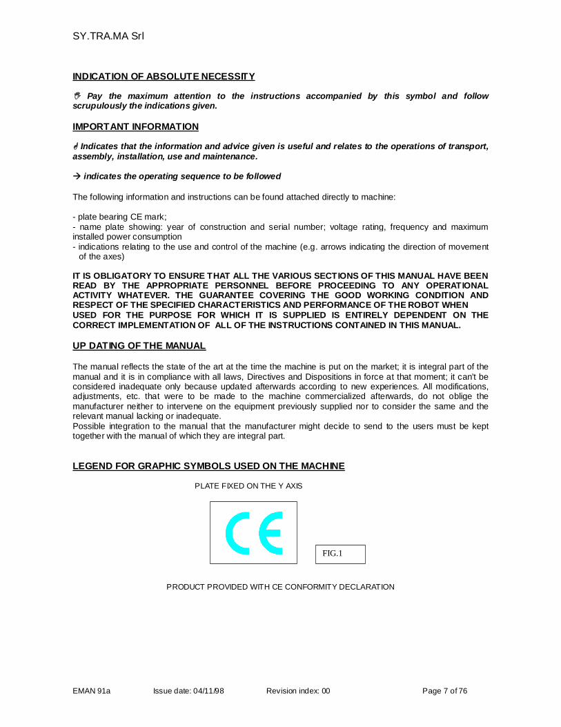
PLATE FIXED ON THE ELECTRICAL CABINET AND ON THE Y AXIS
FIG. 2
MAINTAINING THE PLATES IN A LEGIBLE CONDITION
The plates must be maintained in such condition as to render legible all of the information contained therein.These elements of identification are to be used in all communications with the manufacturer, for examplewhen ordering spare parts or when requesting information and assistance. Should the plate deteriorate withtime or use to the point where any individual item is no longer readable, we recommend that a replacementbe requested from the manufacturer quoting the data contained in this manual or on the original plate.ATTENTION: the plates must not be removed; it is absolutely forbidden to put on the machine otherplates that can compromise the security of the system.
SY.TRA.MA Srl
EMAN 91a Issue date: 04/11/98 Revision index: 00 Page 9 of 76
CONFORMITY WITH DIRECTIVES - DECLARATIONS
This technical document "User and maintenance manual for robots model 91" is identified with thereference code “SY.TRA.MA EMAN 91a, constructed by SY.TRA.MA SRL - Via Lombardia ,30 - 20060
Vignate (MI) Italy
The document has been drawn up taking into account the unified rules set out in UNI-EN 292 1st part withparticular reference to the first part, item 3.20 and the second part, item 5.
Our robots are produced in compliance with the E.E.C. Directive 98/37 CE and followingamendments 91/368 CEE, 93/44 CEE and 93/68 CEE denominated the Machinery Directive (seedeclaration according to annexe II A) EMC 89/336 CEE, LVD 93/68 CEE.
When the necessary safety guards provided for in the above regulations have not been applied to themachines, the machines themselves can only be brought into service after having been equipped with therequired accident protection devices as stipulated in the Directive (see declaration according to annexe II B)
RESPONSIBILITY
The various instructions contained in this manual are to be considered additional to all legalrequirements and in no way substitute the duties and regulations relating to safety and theprevention of accidents as defined in current legislation.
With reference to the information contained in this instruction manual SY.TRA.MA declines any responsibilityin the following cases:
- use contrary to the current national or local legislation regarding health, safety and accident prevention;- errors in the preparation, setting up or programming of the injection moulding machine and any other plantand equipment with which the robot may be required to work;- failure (errors or omissions) to observe the instructions contained in the manual;- defects in the electrical power supply system;- unauthorised modifications to the machine;- use by not trained staff.
NOTE: The destination of the use and the configurations of the machine as foreseen are the soleadmitted by the manufacturer. Do not try to use the robot in disagreement with the indications given.
GUARANTEE OF CONSTRUCTOR
The user, in order to benefit from the given guarantee by the manufacturer must scrupulously observe theprescriptions indicated in the manual and in particular:
-always operate within the use limits of the equipment-always make a constant and diligent maintenance-assign the use of the machine to staff with real skills, abilities and adequately trained to the purpose.

SY.TRA.MA Srl
EMAN 91a Issue date: 04/11/98 Revision index: 00 Page 10 of 76
2. THE MODEL 91 ROBOTS
INTRODUCTION
The model 91 cartesian axis robots have been constructed to operate in covered areas and in situationswhere the environmental conditions are in line with the values indicated in the chapter "DIMENSIONS ANDTECHNICAL CHARACTERISTICS".
Technologically speaking, these machines represent the top end of the range for the movement andhandling of injection moulded plastic components.
The use of extruded aluminium sections in the construction of many of the components gives the due degreeof stiffness to the moving parts whilst reducing the weight to the minimum.
BRUSHLESS servomotors are used.
The machines can be fitted with: numerical control, programming keyboard and commanding TME separatedfrom the electric cabinet.
The possibilities of dialogue using the keyboard-three permit the visualization of the fault tracing diagnosisand the capacity to memorize a large number of programs rendering this machine extremely "user friendly".
The robot is supplied for installation on plastic injection moulding machine or as part of complex lines. It cancommunicate with the other machines in the line in which it is situated by means of an interface designedand produced according to the rules defined in EUROMAP 12
The interface between the injection moulding machine and the manipulator allows the installation of a safetymicroswitch and emergency devices. It is the responsibility of the installer to ensure the correctness of theirinstallation.
SY.TRA.MA Srl
EMAN 91a Issue date: 04/11/98 Revision index: 00 Page 11 of 76
PERFORMANCE AND OPERATING CHARACTERISTICS ("intended use")
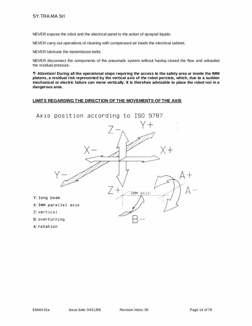
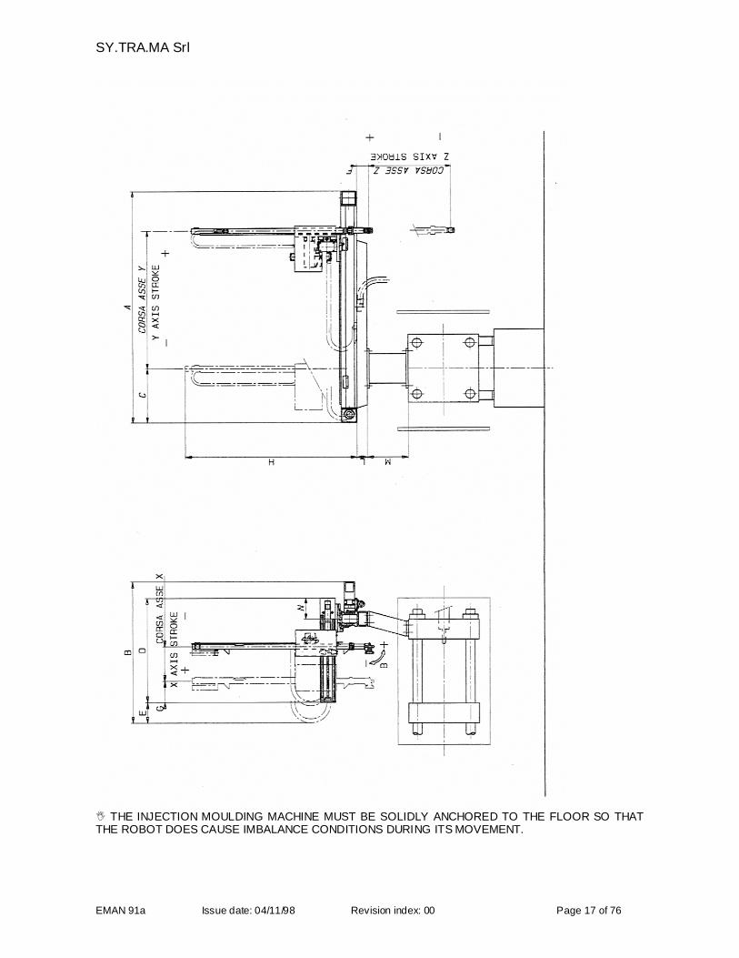
Robots are machines which move items automatically from one point to another. They move in the followingdirections ± X ± Y ± Z ± B and through the spaces shown in the diagram at page 17 as prescribed in ISO9787 represented at page 14.
The axes are clearly identified on the machine by means of letters (rivetted). The tilting movement of thewrist, ± B axis, is achieved by means of a pneumatic cylinder situated on the terminal section of the(telescopic) Z axis. Normally the robot is attached to the fixed platen of the injection moulding machine. Adifferent height of support may be provided according to the circumstances of the installation such as:- dimensions of the injection moulding machine- characteristics of the part to be handled- height of the unloading position, etc.
ESTIMATED USE
Thanks to their speed and versatility our robots are used to perform the following tasks:
- picking up and unloading parts with the shape and other characteristics defined (see specificationsincluded in the order confirmation)
- further operations downstream of the injection moulding machine (sprue cutting, conformation, hot printing,etc.)- palletizing in boxes- palletizing in thermoformed trays- palletization on pallet of any number of articles- positioning of metallic inserts or other materials in the mould.
To be more precise the "intended use" is understood to be the one described in the order confirmationNo._____________ it refers to.
NOT ESTIMATED USE
Our robots MUST NOT be used to perform the following tasks or in the following conditions :
- the movement of heavy loads other than those specified in the intended use;- mounting on the robot of machine tools, such as milling, sanding or perforating machines unless
specifically approved by SY.TRA.MA- outdoors or in uncovered areas;- in locations in which there is a risk of explosion;- in any location which does not meet the requirements as specified in the section regarding technical
requirements of the aforementioned order confirmation.
WHAT ALWAYS TO DO
FORESEEN USE: METHODS AND PRECAUTIONS
The correct use of the robot allows the full use of the performances that the machine can offer, safely. Thesepotentials are ONLY granted when scrupulously respecting the indications below described and confirmed inthe various paragraphs of this manual; therefore:
ALWAYS follow the indications and the instructions described in the installation, use and maintenancemanual
ALWAYS respect the indications in the attached electrical schemes for the electrical maintenanceintervention,
ALWAYS respect the instructions indicated in the programming manuals.
SY.TRA.MA Srl
EMAN 91a Issue date: 04/11/98 Revision index: 00 Page 12 of 76
ALWAYS scupulously follow the procedures described in this manual for the start up and switching off of therobot.
ALWAYS verify the correspondence of the performances of the robot according to the service it is destinedto (work cycles, timings, product to be handled).
ALWAYS make sure that the robot works in places protected against atmospheric agents.
ALWAYS respect the signals on the robot. Their observance is a safety precaution; these signals must bealways perfectly legible.
ALWAYS make sure, before starting up the manipulator that its operating area is free from obstacles.
ALWAYS make sure of the adequate status of conservation (cleaning, lubrication) and maintenance of therobot and all its components.
ALWAYS check the functional efficiency of the safety devices mounted on the safety guards.
ALWAYS check the correct anchorage in position of the safety guards, of the robot, of the support , of themechanical and electrical limit switches.
ALWAYS at the end of the work check that the robot has been switched off in the “parking” position so thatcollision dangers can be prevented.
ALWAYS test the functionality of the stop/emergency buttons.
ALWAYS check the integrity and the efficency of the push button panel.
ALWAYS remove the robot supply voltage in case of inspection, repair, routine maintenance interventions.
ALWAYS, for any operation, use suitable work clothes, according to the safety regulations in the workingplace.
ALWAYS signal possible faults of function (defects, suspicious breaking, movements not correct and noisebeyond regular value) to the Responsible of the Department and put the machine in conditions of out oforder.
ALWAYS respect the program of interventions of maintenance and registration, remember to fill in theregister of the maintenance operations integrating the same at every check with the relevant remarks.
ALWAYS check that the mechanical and electrical limit switches bound the working area of the robot withinthe protected area.
SY.TRA.MA Srl
EMAN 91a Issue date: 04/11/98 Revision index: 00 Page 13 of 76
WHAT NEVER TO DO
NOT ALLOWED, UNFORESEEN USE AND CONTRAINDICATIONS OF USE
The use of the manipulator for not allowed manoeuvres, its improper use and the lack of maintenance cancause danger situations for personal safety and damage for the work environment as well as for thefunctionality and safety of the machine itself.The actions below described, that can not obviously cover the full range of possibilit ies of “bad use” of therobot, are anyhow those reasonably supposed to occurr and they are absolutely forbidden; therefore:
NEVER use the robot for services other than those to which it is destined, avoid the use as point of supportfor stairs or like a basis for lamps replacement, etc.
NEVER use the robot for operations of haulage or dragging.
NEVER use the frames of the robot as grounding for welders.
NEVER use the robot for picking-up and loads deplacement operations.
NEVER crash with the robot against frames or other machines and equipments.
NEVER utilize the robot in unforeseen environment conditions. Respect the values of the temperatures, from+5°C to +40°C and humidity, from 30% to 80%.
NEVER use the robot outdoor.
NEVER use the robot in places with risk of explosion
NEVER permit the use of the robot to not qualified or minus of 16 years personnel
NEVER use the robot if not psychophysically fit.
NEVER modify the performing/functional characteristics of the robot and its components.
NEVER modify, decalibrate or make inefficaciuos the safety electrical devices and/or cause tampering to theequipment.
NEVER remove completely or partially or only slacken from the apposite anchorages the safety guards.
NEVER execute temporary repairs or interventions of restore not in conformity with the instructions.
NEVER utilize not original spare parts or not suggested by SYTRAMA
NEVER commit the operations of maintenance and repairs to not specialized and trained personnel.
NEVER leave the manipulator at the end of the work without having made the relevant safety procedures.
NEVER make routine maintenance operations, inspections or repairs without having put the robot out ofservice and activate the relevant safety procedure.
NEVER during the maintenance operations:-use not suitable means-operate without the personal safety devices-intervene without blocking the disconnetting switch of feeding and assuring adequate lighting is in theoperative area.
NEVER use the robot if not perfectly corresponding in all of its operating functions.
NEVER clean the robot with aggressive liquids or dangerous for its components
SY.TRA.MA Srl
EMAN 91a Issue date: 04/11/98 Revision index: 00 Page 14 of 76
NEVER expose the robot and the electrical panel to the action of sprayed liquids.
NEVER carry out operations of cleaning with compressed air inside the electrical cabinet.
NEVER lubricate the transmission belts.
NEVER disconnect the components of the pneumatic system without having closed the flow and unloadedthe residual pressure. Attention! During all the operational steps requiring the access to the safety area or inside the IMMplatens, a residual risk represented by the vertical axis of the robot persists, which, due to a suddenmechanical or electric failure can move vertically. It is therefore advisable to place the robot not in adangerous area.
LIMITS REGARDING THE DIRECTION OF THE MOVEMENTS OF THE AXIS
SY.TRA.MA Srl
EMAN 91a Issue date: 04/11/98 Revision index: 00 Page 15 of 76
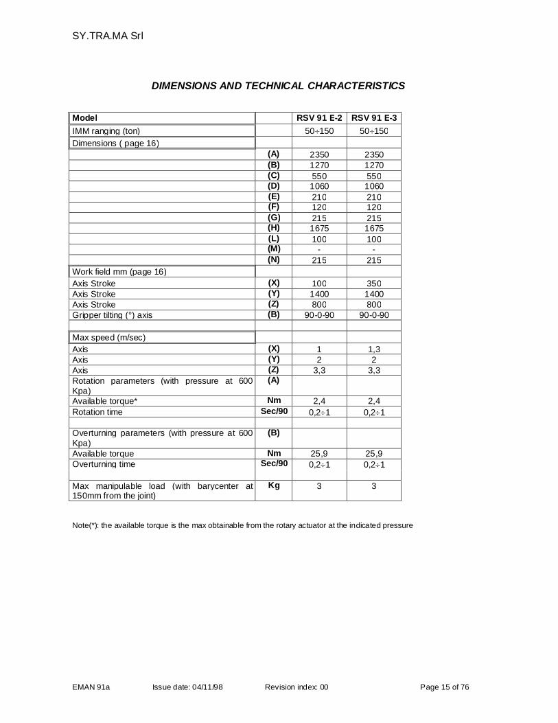
DIMENSIONS AND TECHNICAL CHARACTERISTICS
Model RSV 91 E-2 RSV 91 E-3
IMM ranging (ton) 50150 50150
Dimensions ( page 16)(A) 2350 2350(B) 1270 1270(C) 550 550(D) 1060 1060(E) 210 210(F) 120 120(G) 215 215(H) 1675 1675(L) 100 100(M) - -(N) 215 215
Work field mm (page 16)
Axis Stroke (X) 100 350Axis Stroke (Y) 1400 1400Axis Stroke (Z) 800 800Gripper tilting (°) axis (B) 90-0-90 90-0-90
Max speed (m/sec)
Axis (X) 1 1,3Axis (Y) 2 2Axis (Z) 3,3 3,3Rotation parameters (with pressure at 600Kpa)
(A)
Available torque* Nm 2,4 2,4
Rotation time Sec/90 0,21 0,21
Overturning parameters (with pressure at 600Kpa)
(B)
Available torque Nm 25,9 25,9Overturning time Sec/90 0,21 0,21
Max manipulable load (with barycenter at150mm from the joint)
Kg 3 3
Note(*): the available torque is the max obtainable from the rotary actuator at the indicated pressure
SY.TRA.MA Srl
EMAN 91a Issue date: 04/11/98 Revision index: 00 Page 16 of 76
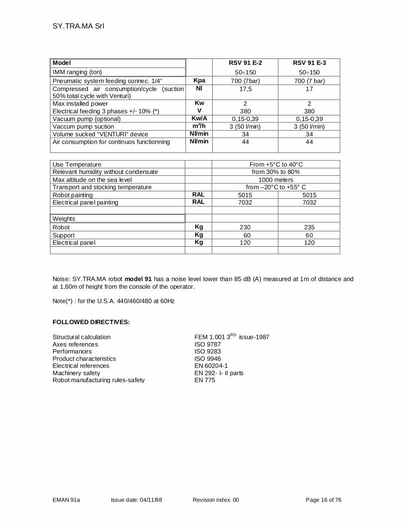
Model RSV 91 E-2 RSV 91 E-3
IMM ranging (ton) 50150 50150
Pneumatic system feeding connec. 1/4” Kpa 700 (7bar) 700 (7 bar)
Compressed air consumption/cycle (suction50% total cycle with Venturi)
Nl 17,5 17
Max installed power Kw 2 2Electrical feeding 3 phases +/- 10% (*) V 380 380Vacuum pump (optional) Kw/A 0,15-0,39 0,15-0,39Vaccum pump suction m3/h 3 (50 l/min) 3 (50 l/min)Volume sucked “VENTURI” device Nl/min 34 34Air consumption for continuos functionning Nl/min 44 44
Use Temperature From +5°C to 40°CRelevant humidity without condensate from 30% to 80%
Max altitude on the sea level 1000 metersTransport and stocking temperature from –20°C to +55° C
Robot painting RAL 5015 5015Electrical panel painting RAL 7032 7032
Weights
Robot Kg 230 235
Support Kg 60 60Electrical panel Kg 120 120
Noise: SY.TRA.MA robot model 91 has a noise level lower than 85 dB (A) measured at 1m of distance andat 1,60m of height from the console of the operator.
Note(*) : for the U.S.A. 440/460/480 at 60Hz
FOLLOWED DIRECTIVES:
Structural calculation FEM 1.001 3RD issue-1987Axes references ISO 9787Performances ISO 9283Product characteristics ISO 9946Electrical references EN 60204-1Machinery safety EN 292- I- II partsRobot manufacturing rules-safety EN 775
SY.TRA.MA Srl
EMAN 91a Issue date: 04/11/98 Revision index: 00 Page 17 of 76
THE INJECTION MOULDING MACHINE MUST BE SOLIDLY ANCHORED TO THE FLOOR SO THATTHE ROBOT DOES CAUSE IMBALANCE CONDITIONS DURING ITS MOVEMENT.
SY.TRA.MA Srl
EMAN 91a Issue date: 04/11/98 Revision index: 00 Page 18 of 76
PACKING AND TRANSPORT
The robot will be stirruped and anchored on special brackets to facilitate movement during the phases oftransport. It will normally be delivered with the axis assembled; in the same packing, which varies
according to the destination, the following units may be included (check these details on your orderconfirmation:
- main control panel- cable for interfacing with the moulding machine- programming keyboard and control TME- support- gripper (as specified by the customer) if required
The machine is protected against corrosion by means of special products (rust inhibiting protective oils)which also act as lubricants.Recent environmental legislations require that the used packing materials must not be abandoned, but mustbe taken to an authorized centre for waste collection and disposal.
Transport must be effected by qualified hauliers to ensure that the material is moved with due care.This operation may be arranged by, and at the expense of the customer or by SY.TRA.MA (this will havebeen defined on the order confirmation)
As soon as the goods are received they are to be taken to the area in which they are to be installed.
check the state of the packing verify the contents against the packing/delivery note check each item singularly to verify any possible damage in case of damage take photographs and advise SY.TRA.MA immediately to ensure the prompt despatchof any necessary spare parts.
3. INSTALLATION INSTRUCTIONS
3.1 PRE-INSTALLATION OPERATIONS ( at the user charge)
In order to allow the installation of the robot it is necessary to proceed firstly the operations relating to:
PREPARATION OF THE AREA
Prepare the installation area with proper notices according to ISO 7000 Disposition to signal the presence ofoperations with moving picking-up means.
SY.TRA.MA Srl
EMAN 91a Issue date: 04/11/98 Revision index: 00 Page 19 of 76
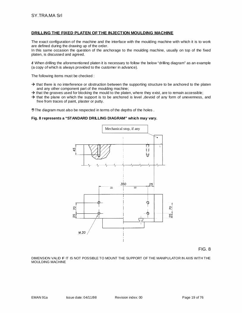
DRILLING THE FIXED PLATEN OF THE INJECTION MOULDING MACHINE
The exact configuration of the machine and the interface with the moulding machine with which it is to workare defined during the drawing up of the order.In this same occasion the question of the anchorage to the moulding machine, usually on top of the fixedplaten, is discussed and agreed.
When drilling the aforementioned platen it is necessary to follow the below “drilling diagram” as an example(a copy of which is always provided to the customer in advance).
The following items must be checked :
that there is no interference or obstruction between the supporting structure to be anchored to the platenand any other component part of the moulding machine;
that the grooves used for blocking the mould to the platen, where they exist, are to remain accessible; that the plane on which the support is to be anchored is level ,devoid of any form of unevenness, and
free from traces of paint, plaster or putty.
The diagram must also be respected in terms of the depths of the holes .
Fig. 8 represents a “STANDARD DRILLING DIAGRAM” which may vary.
Mechanical stop, if any
FIG. 8
DIMENSION VALID IF IT IS NOT POSSIBLE TO MOUNT THE SUPPORT OF THE MANIPULATOR IN AXIS WITH THEMOULDING MACHINE
SY.TRA.MA Srl
EMAN 91a Issue date: 04/11/98 Revision index: 00 Page 20 of 76
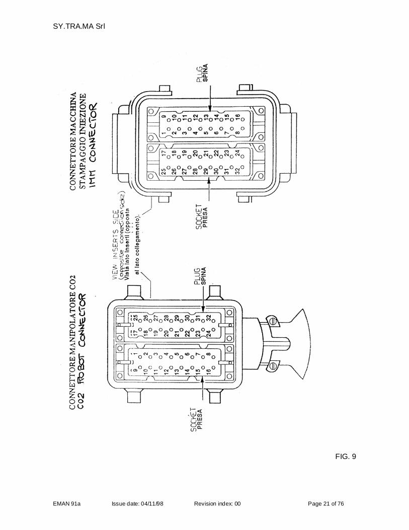
INTERFACING THE ROBOT WITH THE MOULDING MACHINE ACCORDING TOTHE EUROMAP 12 REGULATIONS
FOR THE ATTENTION OF YOUR QUALIFIED ELECTRICIANS
Use the wiring diagram shown below for connecting the robot to the moulding machine
ATTENTION : the costs of the interfacing operation are at the customers expense unless otherwiseagreed and specified in the order confirmation.SY.TRA.MA declines any responsibility for any malfunctions and reductions in the level of securityshould the interfacing be carried out in a different manner from that shown in this manual.
Method: Std. with 32 pin connectorThe injection moulding machine is connected to the robot by means of a HAN 32 A plug-in connection.The connections for both the plug side (from 1-16) and the socket side (from 17-32) must be arranged withinthe control panel of the moulding machine.
ARRANGEMENT OF THE CONNECTIONS WITH THE MOULDING MACHINE (SEE TABLE ONFOLLOWING PAGE)
Contact points Description plug side
1;9 Emergency stop2;16 Moulding machine open3;11 Moulding machine protection (gates) closed4;16 Ejector plate withdrawn5;16 Ejector plate forward6;16 Free7;16 Free8;16 Part rejected for quality control10;16 Moulding machine in automatic cycle12;16 Moulding machine closed(16= power supply voltage – common from robot)
Contact points Description socket side
17;32 Permission/OK for closure of injection moulding machine18;26 Safe to open and close moulding machine19;27 Emergency stop20;32 Robot inserted in production cycle21;32 Permission for withdrawal of ejectors22;32 Permission for advance of ejectors23;32 Free24,32 Free(32 = power supply voltage – common from moulding machine)
SY.TRA.MA Srl
EMAN 91a Issue date: 04/11/98 Revision index: 00 Page 21 of 76
FIG. 9
SY.TRA.MA Srl
EMAN 91a Issue date: 04/11/98 Revision index: 00 Page 22 of 76
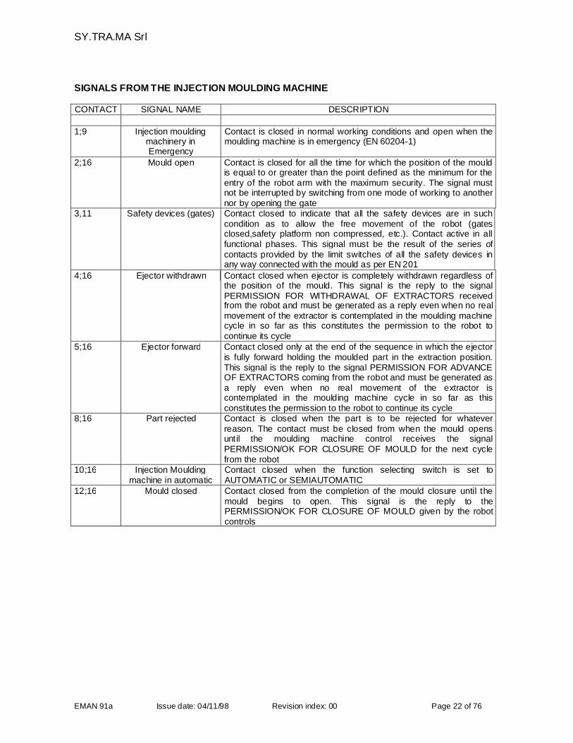
SIGNALS FROM THE INJECTION MOULDING MACHINE
CONTACT SIGNAL NAME DESCRIPTION
1;9 Injection mouldingmachinery inEmergency
Contact is closed in normal working conditions and open when themoulding machine is in emergency (EN 60204-1)
2;16 Mould open Contact is closed for all the time for which the position of the mouldis equal to or greater than the point defined as the minimum for theentry of the robot arm with the maximum security. The signal mustnot be interrupted by switching from one mode of working to anothernor by opening the gate
3,11 Safety devices (gates) Contact closed to indicate that all the safety devices are in suchcondition as to allow the free movement of the robot (gatesclosed,safety platform non compressed, etc.). Contact active in allfunctional phases. This signal must be the result of the series ofcontacts provided by the limit switches of all the safety devices inany way connected with the mould as per EN 201
4;16 Ejector withdrawn Contact closed when ejector is completely withdrawn regardless ofthe position of the mould. This signal is the reply to the signalPERMISSION FOR WITHDRAWAL OF EXTRACTORS receivedfrom the robot and must be generated as a reply even when no realmovement of the extractor is contemplated in the moulding machinecycle in so far as this constitutes the permission to the robot tocontinue its cycle
5;16 Ejector forward Contact closed only at the end of the sequence in which the ejectoris fully forward holding the moulded part in the extraction position.This signal is the reply to the signal PERMISSION FOR ADVANCEOF EXTRACTORS coming from the robot and must be generated asa reply even when no real movement of the extractor iscontemplated in the moulding machine cycle in so far as thisconstitutes the permission to the robot to continue its cycle
8;16 Part rejected Contact is closed when the part is to be rejected for whateverreason. The contact must be closed from when the mould opensuntil the moulding machine control receives the signalPERMISSION/OK FOR CLOSURE OF MOULD for the next cyclefrom the robot
10;16 Injection Mouldingmachine in automatic
Contact closed when the function selecting switch is set toAUTOMATIC or SEMIAUTOMATIC
12;16 Mould closed Contact closed from the completion of the mould closure until themould begins to open. This signal is the reply to thePERMISSION/OK FOR CLOSURE OF MOULD given by the robotcontrols
SY.TRA.MA Srl
EMAN 91a Issue date: 04/11/98 Revision index: 00 Page 23 of 76
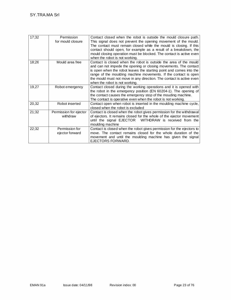
17;32 Permissionfor mould closure
Contact closed when the robot is outside the mould closure path.This signal does not prevent the opening movement of the mould.The contact must remain closed while the mould is closing. If thiscontact should open, for example as a result of a breakdown, themould closing operation must be blocked. The contact is active evenwhen the robot is not working.
18;26 Mould area free Contact is closed when the robot is outside the area of the mouldand can not impede the opening or closing movements. The contactis open when the robot leaves the starting point and comes into therange of the moulding machine movements. If the contact is openthe mould must not move in any direction. The contact is active evenwhen the robot is not working.
19,27 Robot emergency Contact closed during the working operations and it is opened withthe robot in the emergency position (EN 60204-1). The opening ofthe contact causes the emergency stop of the mouding machine.The contact is operative even when the robot is not working.
20,32 Robot inserted Contact open when robot is inserted in the moulding machine cycle,closed when the robot is excluded
21;32 Permission for ejectorwithdraw
Contact is closed when the robot gives permission for the withdrawalof ejectors. It remains closed for the whole of the ejector movementuntil the signal EJECTOR WITHDRAW is received from themoulding machine
22;32 Permission forejector forward
Contact is closed when the robot gives permission for the ejectors tomove. The contact remains closed for the whole duration of themovement and until the moulding machine has given the signalEJECTORS FORWARD.
SY.TRA.MA Srl
EMAN 91a Issue date: 04/11/98 Revision index: 00 Page 24 of 76
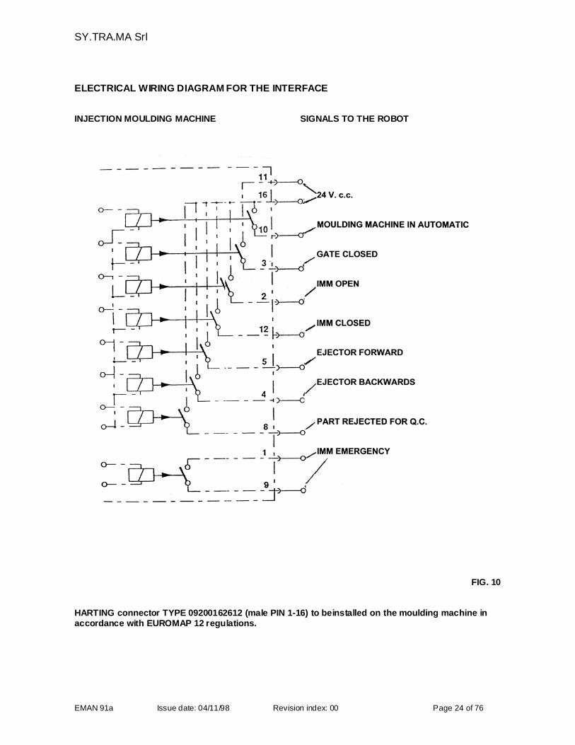
ELECTRICAL WIRING DIAGRAM FOR THE INTERFACE
INJECTION MOULDING MACHINE SIGNALS TO THE ROBOT
FIG. 10
HARTING connector TYPE 09200162612 (male PIN 1-16) to beinstalled on the moulding machine inaccordance with EUROMAP 12 regulations.
SY.TRA.MA Srl
EMAN 91a Issue date: 04/11/98 Revision index: 00 Page 25 of 76
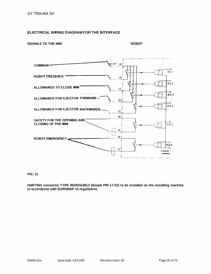
ELECTRICAL WIRING DIAGRAM FOR THE INTERFACE
SIGNALS TO THE IMM ROBOT
FIG. 11
HARTING connector TYPE 09200162813 (female PIN 17-32) to be installed on the moulding machinein accordance with EUROMAP 12 regulations.
SY.TRA.MA Srl
EMAN 91a Issue date: 04/11/98 Revision index: 00 Page 26 of 76
PREPARING THE ELECTRICAL CONNECTIONS
FOR THE ATTENTION OF THE FACTORY OR DEPARTMENTAL MANAGER
The feeding line inside the electrical panel has been protected using some fuses having an interruptionpower equal to 100 KA.The customer during the electrical connection must make sure that this power is enough for the 60 A shortcircuit current. Moreover in the line phase wires must be free from disturbance and the earth wire must beconnected to the main earth of the supply mains, according to ISO EN 60204-1.P.S.: following to the filter mounted inside the electrical cabinet according to EMC 89/336 CEE, as regards tothe use of differential limiting devices, it must be noted that all filters RFI absorb a considerable current onthe earth connection of the drive cards; it is therefore necessary to foresee differential devices with highintervention threshold (>300 mA) and adjustable to obtain the best.
PREPARING THE CONNECTIONS TO THE COMPRESSED AIR SYSTEM
FOR THE ATTENTION OF THE FACTORY OR DEPARTMENTAL MANAGER
The customer must provide, in the immediate vicinity of the equipment a supply line of compressed air at 700Kpa (7 bar) capable of delivering not less than 65Nl/min de-humidified air and connected to the robot bymeans of an 8 mm. internal diameter pipe. To the robot you must connect with a removable pipe and withthe positioning of a manual valve that can be locked.
LOADING THE APPROPRIATE MOULD ONTO THE INJECTION MOULDING MACHINE
FOR THE ATTENTION OF THE FACTORY OR DEPARTMENTAL MANAGER
Before the arrival of SY.TRA.MA installation staff the customer must ensure that the appropriate mould forthe production of the articles to be handled by the robot has been mounted on the moulding machine.
PREPARING THE GRIPPER
FOR THE ATTENTION OF THE FACTORY OR DEPARTMENTAL MANAGER
When the gripper is not manufactured by SY.TRA.MA (as detectable from the order confirmation) thecustomer must ensure that the gripper is available in due time to let our installation staff carry out themounting and the approval tests.
PREPARING THE HOISTING MEANS
FOR THE ATTENTION OF THE FACTORY OR DEPARTMENTAL MANAGER
In order to install the robot and its support on top of the moulding machine the customer must provide anadequate lifting device (bridge or gib crane with a sufficient lifting capacity – check weights and otherdimensions under the heading “DIMENSIONS AND TECHNICAL CHARACTERISTICS”).The personnelmade available for this operation must be qualified to use the aforementioned lifting devices and the areamust be adequately identified, using appropriate warning signs, as a zone in which such devices are inoperation.
Before carrying out the mounting and installation operations, make sure the instructiondocumentation is available and check that this documentation refers to the machine.
SY.TRA.MA Srl
EMAN 91a Issue date: 04/11/98 Revision index: 00 Page 27 of 76
3.2 INSTALLATION OF THE ROBOT
THE INSTALLATION OPERATIONS ARE ALWAYS CARRIED OUT BY OUR SPECIALIZEDINSTALLATION STAFF OR BY TECHNICIANS AUTHORIZED BY SY.TRA.MA WHO ALSO INSTRUCTYOUR SPECIALIZED PERSONNEL
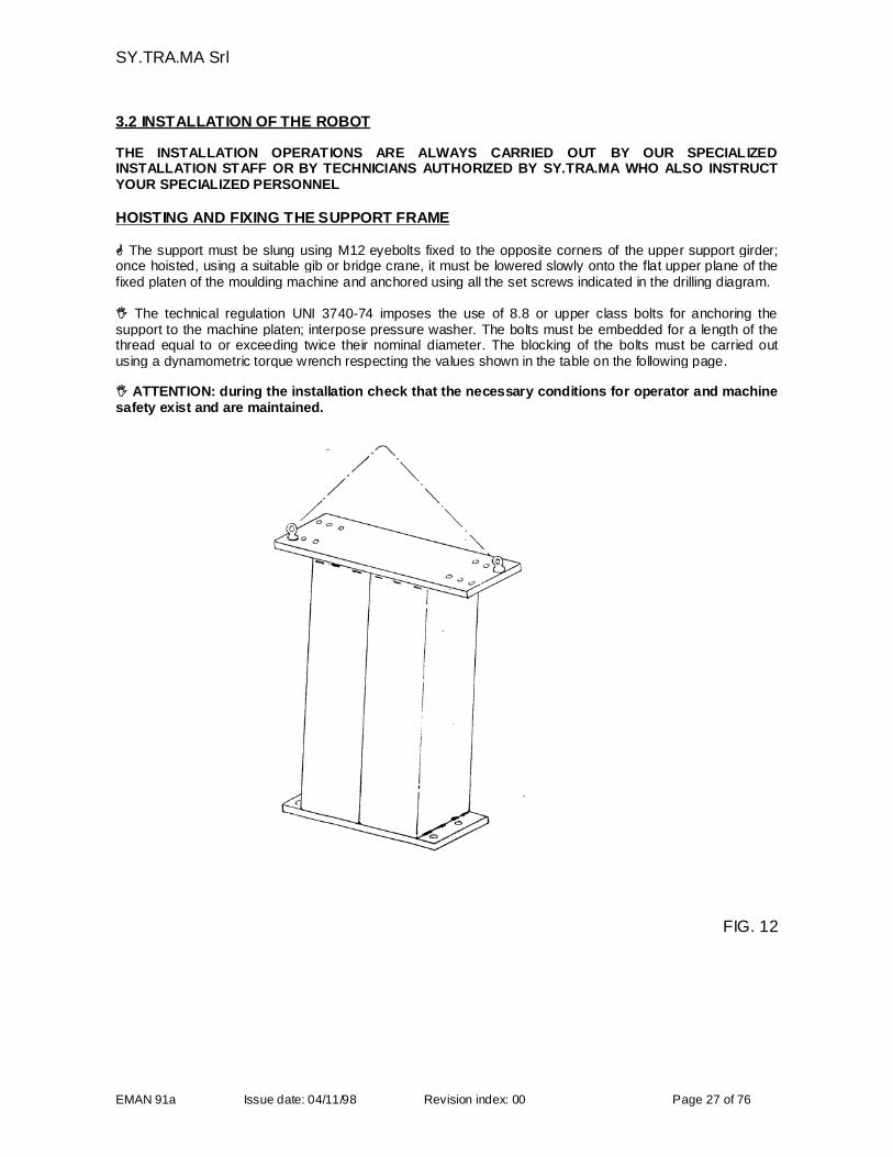
HOISTING AND FIXING THE SUPPORT FRAME
The support must be slung using M12 eyebolts fixed to the opposite corners of the upper support girder;once hoisted, using a suitable gib or bridge crane, it must be lowered slowly onto the flat upper plane of thefixed platen of the moulding machine and anchored using all the set screws indicated in the drilling diagram.
The technical regulation UNI 3740-74 imposes the use of 8.8 or upper class bolts for anchoring thesupport to the machine platen; interpose pressure washer. The bolts must be embedded for a length of thethread equal to or exceeding twice their nominal diameter. The blocking of the bolts must be carried outusing a dynamometric torque wrench respecting the values shown in the table on the following page.
ATTENTION: during the installation check that the necessary conditions for operator and machinesafety exist and are maintained.
FIG. 12
SY.TRA.MA Srl
EMAN 91a Issue date: 04/11/98 Revision index: 00 Page 28 of 76
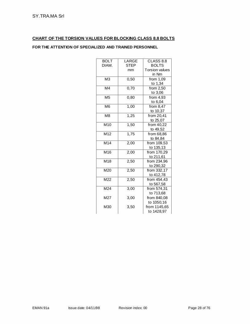
CHART OF THE TORSION VALUES FOR BLOCKING CLASS 8.8 BOLTS
FOR THE ATTENTION OF SPECIALIZED AND TRAINED PERSONNEL
BOLTDIAM.
LARGESTEPmm
CLASS 8.8BOLTS
Torsion valuesin Nm
M3 0,50 from 1,09to 1,34
M4 0,70 from 2,50to 3,06
M5 0,80 from 4,93to 6,04
M6 1,00 from 8,47to 10,37
M8 1,25 from 20,41to 25,07
M10 1,50 from 40,22to 49,52
M12 1,75 from 68,86to 84,84
M14 2,00 from 109,53to 135,13
M16 2,00 from 170,29to 211,61
M18 2,50 from 234,96to 290,32
M20 2,50 from 332,17to 412,78
M22 2,50 from 454,43to 567,58
M24 3,00 from 574,31to 713,68
M27 3,00 from 840,08to 1050,16
M30 3,50 from 1145,65to 1428,97
SY.TRA.MA Srl
EMAN 91a Issue date: 04/11/98 Revision index: 00 Page 29 of 76
HOISTING AND FIXING THE ROBOT
FOR THE ATTENTION OF SPECIALIZED AND TRAINED PERSONNEL
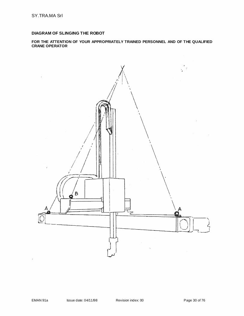
The robot is mounted on special beams to facilitate transport and movement in the work area by means offork lift trucks and the axes are locked in their position. Use a suitable gib or bridge crane to position the robot above the moulding machine. The robot is to beslung using three (3) belts ( see figure on the following page )
The lifting eyebolts are those showed in the picture with the letter (A). The eyebolt (B) is used only for thebalancing of the load. An anomalus use may damage the sliding blocks of the Y axis.
Before proceeding check that :
- the carriage on the Y axis is positioned at the mid point of the main beam ( Y +/- 0) and is kept in the rightposition by the brackets- the carriage on the X axis is as far back as possible towards the main beam (X -) and is connected- the Z axis is in its highest possible position (Z -) and kept by the break of the motor Hook two (2) belts of equal length at the Y beam one on each side of the carriage and one under theX beam on the Z axis side. Check that the belts are sufficiently strong verifying also the weights table under the heading Technical
Characteristics. The slinging must correspond to the drawing provided and the belts must be separatesingle sections as the weight is not evenly distributed.
Lift the robot slightly to check that the slinging is correct. Lower it slowly to the ground again, keeping the belts in tension in order to remove the transport brackets. Hoist the robot and position it in the correct position above the support still keeping the belts in
tension. Block the robot to its support using only class 8.8 bolts in line with the technical regulations UNI
3740-74; the blocking of the bolts must be carried out using a dynamometric torque wrench respectingthe values shown in the table on the previous page.
ATTENTION : during the installation check that the necessary conditions for operator and machinesafety exist and are maintained.
Before putting the robot into use remove the blocks of the X and Y axes and the lifting eyebolts too, thencontrol that the robot moves within the protected area. Close the hole of the M12 eyebolts with the tap,made of plastic.
SY.TRA.MA Srl
EMAN 91a Issue date: 04/11/98 Revision index: 00 Page 30 of 76
DIAGRAM OF SLINGING THE ROBOT
FOR THE ATTENTION OF YOUR APPROPRIATELY TRAINED PERSONNEL AND OF THE QUALIFIEDCRANE OPERATOR

SY.TRA.MA Srl
EMAN 91a Issue date: 04/11/98 Revision index: 00 Page 31 of 76
INSTALLATION OF THE SAFETY GUARDS
FOR THE ATTENTION OF THE FACTORY OR DEPARTMENTAL MANAGER
When SY.TRA.MA have been commissioned to supply the safety guards the system must be installed by ourtechnician, who will also carry out the connection of the microswitches and carry out the approval test of theoperations.
It is essential that all the safety guards are anchored to the shop floor pavement or to the main structuralelements of the moulding machine in such a way that they CANNOT be removed. The structuralcharacteristics of the system and the quality of the microswitches used must conform to the requirementslaid down in the following regulations: EN 60204-1, EN 418, EN294, EN 775, EN 1088, EN 953 (seeCONFORMITY WITH DIRECTIVES -DECLARATIONS ).
SY.TRA.MA Srl
EMAN 91a Issue date: 04/11/98 Revision index: 00 Page 32 of 76
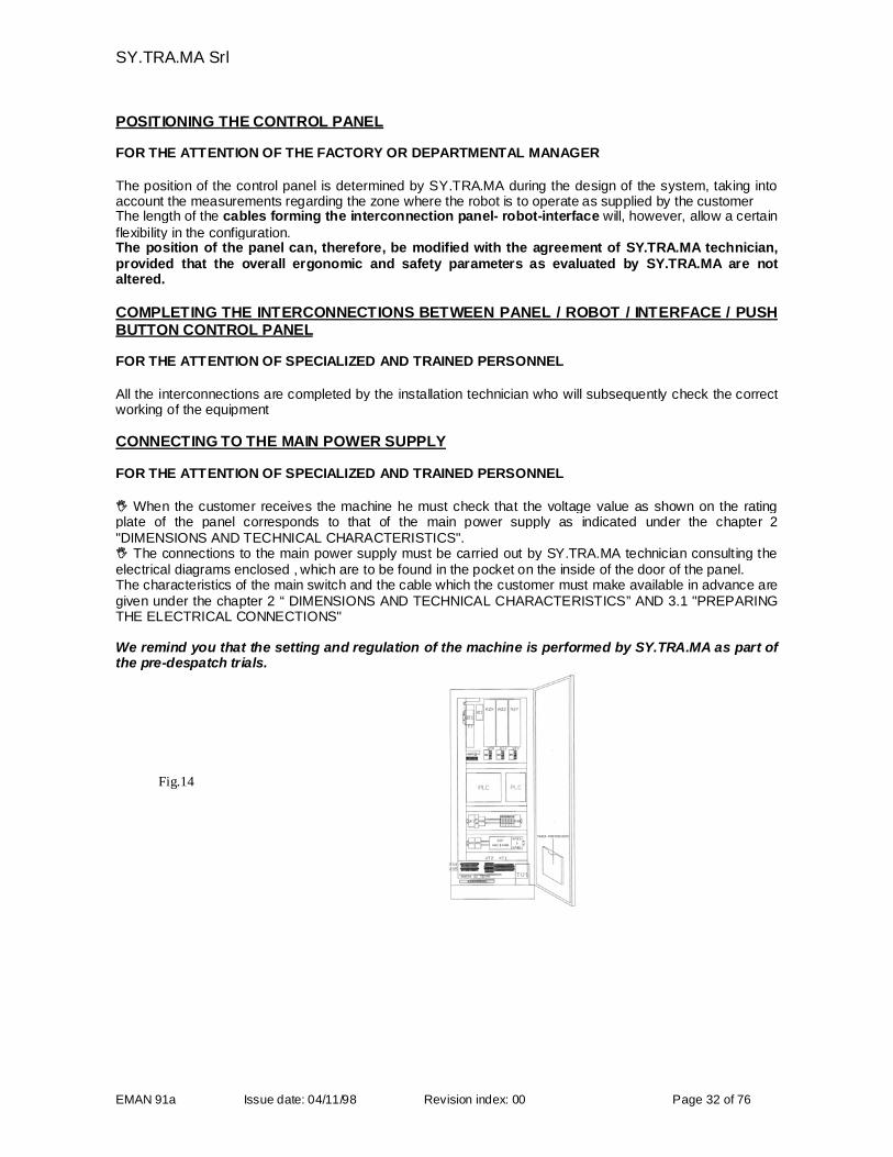
POSITIONING THE CONTROL PANEL
FOR THE ATTENTION OF THE FACTORY OR DEPARTMENTAL MANAGER
The position of the control panel is determined by SY.TRA.MA during the design of the system, taking intoaccount the measurements regarding the zone where the robot is to operate as supplied by the customerThe length of the cables forming the interconnection panel- robot-interface will, however, allow a certainflexibility in the configuration.The position of the panel can, therefore, be modified with the agreement of SY.TRA.MA technician,provided that the overall ergonomic and safety parameters as evaluated by SY.TRA.MA are notaltered.
COMPLETING THE INTERCONNECTIONS BETWEEN PANEL / ROBOT / INTERFACE / PUSHBUTTON CONTROL PANEL
FOR THE ATTENTION OF SPECIALIZED AND TRAINED PERSONNEL
All the interconnections are completed by the installation technician who will subsequently check the correctworking of the equipment
CONNECTING TO THE MAIN POWER SUPPLY
FOR THE ATTENTION OF SPECIALIZED AND TRAINED PERSONNEL
When the customer receives the machine he must check that the voltage value as shown on the ratingplate of the panel corresponds to that of the main power supply as indicated under the chapter 2"DIMENSIONS AND TECHNICAL CHARACTERISTICS". The connections to the main power supply must be carried out by SY.TRA.MA technician consulting theelectrical diagrams enclosed , which are to be found in the pocket on the inside of the door of the panel.The characteristics of the main switch and the cable which the customer must make available in advance aregiven under the chapter 2 “ DIMENSIONS AND TECHNICAL CHARACTERISTICS” AND 3.1 "PREPARINGTHE ELECTRICAL CONNECTIONS"
We remind you that the setting and regulation of the machine is performed by SY.TRA.MA as part ofthe pre-despatch trials.
Fig.14
SY.TRA.MA Srl
EMAN 91a Issue date: 04/11/98 Revision index: 00 Page 33 of 76
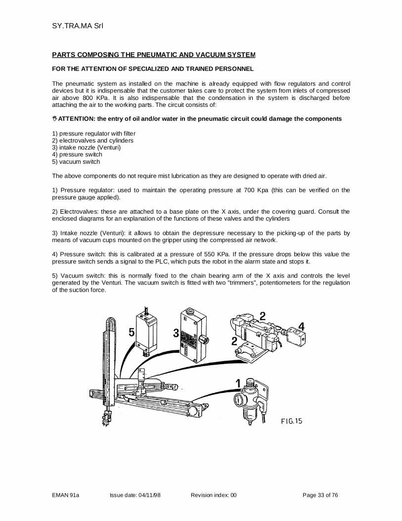
PARTS COMPOSING THE PNEUMATIC AND VACUUM SYSTEM
FOR THE ATTENTION OF SPECIALIZED AND TRAINED PERSONNEL
The pneumatic system as installed on the machine is already equipped with flow regulators and controldevices but it is indispensable that the customer takes care to protect the system from inlets of compressedair above 800 KPa. It is also indispensable that the condensation in the system is discharged beforeattaching the air to the working parts. The circuit consists of:
ATTENTION: the entry of oil and/or water in the pneumatic circuit could damage the components
1) pressure regulator with filter2) electrovalves and cylinders3) intake nozzle (Venturi)4) pressure switch5) vacuum switch
The above components do not require mist lubrication as they are designed to operate with dried air.
1) Pressure regulator: used to maintain the operating pressure at 700 Kpa (this can be verified on thepressure gauge applied).
2) Electrovalves: these are attached to a base plate on the X axis, under the covering guard. Consult theenclosed diagrams for an explanation of the functions of these valves and the cylinders
3) Intake nozzle (Venturi): it allows to obtain the depressure necessary to the picking-up of the parts bymeans of vacuum cups mounted on the gripper using the compressed air network.
4) Pressure switch: this is calibrated at a pressure of 550 KPa. If the pressure drops below this value thepressure switch sends a signal to the PLC, which puts the robot in the alarm state and stops it.
5) Vacuum switch: this is normally fixed to the chain bearing arm of the X axis and controls the levelgenerated by the Venturi. The vacuum switch is fitted with two "trimmers", potentiometers for the regulationof the suction force.
SY.TRA.MA Srl
EMAN 91a Issue date: 04/11/98 Revision index: 00 Page 34 of 76
3.3 IDENTIFICATION OF THE CONTROL UNIT SUPPLIED
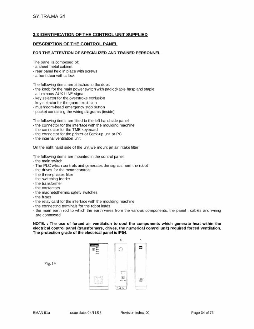
DESCRIPTION OF THE CONTROL PANEL
FOR THE ATTENTION OF SPECIALIZED AND TRAINED PERSONNEL
The panel is composed of:- a sheet metal cabinet- rear panel held in place with screws- a front door with a lock
The following items are attached to the door:- the knob for the main power switch with padlockable hasp and staple- a luminous AUX LINE signal- key selector for the overstroke exclusion- key selector for the guard exclusion- mushroom-head emergency stop button- pocket containing the wiring diagrams (inside)
The following items are fitted to the left hand side panel:- the connector for the interface with the moulding machine- the connector for the TME keyboard- the connector for the printer or Back-up unit or PC- the internal ventilation unit
On the right hand side of the unit we mount an air intake filter
The following items are mounted in the control panel:- the main switch- The PLC which controls and generates the signals from the robot- the drives for the motor controls- the three-phases filter- the switching feeder- the transformer- the contactors- the magnetothermic safety switches- the fuses- the relay card for the interface with the moulding machine- the connecting terminals for the robot leads.- the main earth rod to which the earth wires from the various components, the panel , cables and wiring
are connected
NOTE. : The use of forced air ventilation to cool the components which generate heat within theelectrical control panel (transformers, drives, the numerical control unit) required forced ventilation.The protection grade of the electrical panel is IP54.
Fig. 19
SY.TRA.MA Srl
EMAN 91a Issue date: 04/11/98 Revision index: 00 Page 35 of 76
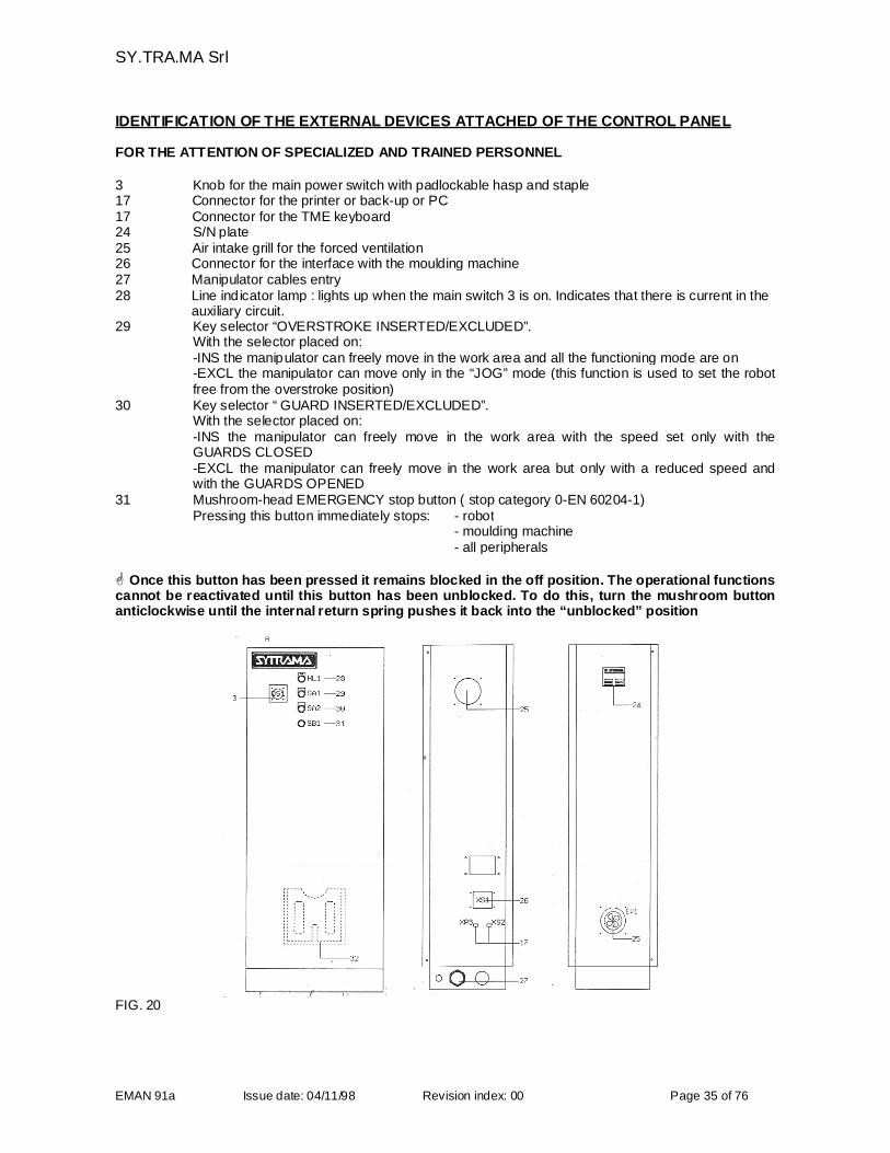
IDENTIFICATION OF THE EXTERNAL DEVICES ATTACHED OF THE CONTROL PANEL
FOR THE ATTENTION OF SPECIALIZED AND TRAINED PERSONNEL
3 Knob for the main power switch with padlockable hasp and staple17 Connector for the printer or back-up or PC17 Connector for the TME keyboard24 S/N plate25 Air intake grill for the forced ventilation26 Connector for the interface with the moulding machine27 Manipulator cables entry28 Line indicator lamp : lights up when the main switch 3 is on. Indicates that there is current in the
auxiliary circuit.29 Key selector “OVERSTROKE INSERTED/EXCLUDED”.
With the selector placed on:-INS the manipulator can freely move in the work area and all the functioning mode are on-EXCL the manipulator can move only in the “JOG” mode (this function is used to set the robotfree from the overstroke position)
30 Key selector “ GUARD INSERTED/EXCLUDED”.With the selector placed on:-INS the manipulator can freely move in the work area with the speed set only with theGUARDS CLOSED-EXCL the manipulator can freely move in the work area but only with a reduced speed andwith the GUARDS OPENED
31 Mushroom-head EMERGENCY stop button ( stop category 0-EN 60204-1)Pressing this button immediately stops: - robot
- moulding machine- all peripherals
Once this button has been pressed it remains blocked in the off position. The operational functionscannot be reactivated until this button has been unblocked. To do this, turn the mushroom buttonanticlockwise until the internal return spring pushes it back into the “unblocked” position
FIG. 20
SY.TRA.MA Srl
EMAN 91a Issue date: 04/11/98 Revision index: 00 Page 36 of 76
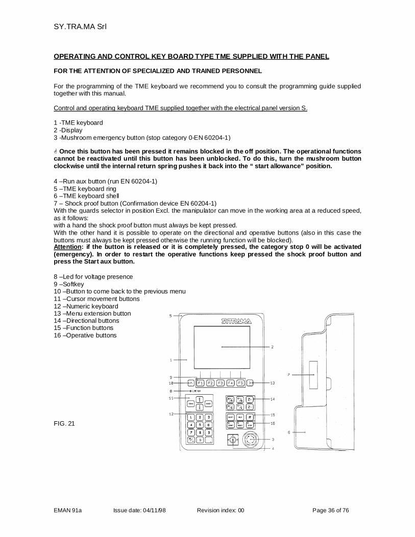
OPERATING AND CONTROL KEY BOARD TYPE TME SUPPLIED WITH THE PANEL
FOR THE ATTENTION OF SPECIALIZED AND TRAINED PERSONNEL
For the programming of the TME keyboard we recommend you to consult the programming guide suppliedtogether with this manual.
Control and operating keyboard TME supplied together with the electrical panel version S.
1 -TME keyboard2 -Display3 -Mushroom emergency button (stop category 0-EN 60204-1)
Once this button has been pressed it remains blocked in the off position. The operational functionscannot be reactivated until this button has been unblocked. To do this, turn the mushroom buttonclockwise until the internal return spring pushes it back into the “ start allowance” position.
4 –Run aux button (run EN 60204-1)5 –TME keyboard ring6 –TME keyboard shell7 – Shock proof button (Confirmation device EN 60204-1)With the guards selector in position Excl. the manipulator can move in the working area at a reduced speed,as it follows:with a hand the shock proof button must always be kept pressed.With the other hand it is possible to operate on the directional and operative buttons (also in this case thebuttons must always be kept pressed otherwise the running function will be blocked).Attention: if the button is released or it is completely pressed, the category stop 0 will be activated(emergency). In order to restart the operative functions keep pressed the shock proof button andpress the Start aux button.
8 –Led for voltage presence9 –Softkey10 –Button to come back to the previous menu11 –Cursor movement buttons12 –Numeric keyboard13 –Menu extension button14 –Directional buttons15 –Function buttons16 –Operative buttons
FIG. 21
SY.TRA.MA Srl
EMAN 91a Issue date: 04/11/98 Revision index: 00 Page 37 of 76
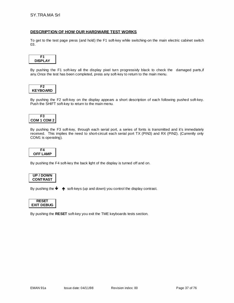
DESCRIPTION OF HOW OUR HARDWARE TEST WORKS
To get to the test page press (and hold) the F1 soft-key while switching-on the main electric cabinet switch03.
F1DISPLAY
By pushing the F1 soft-key all the display pixel turn progressivly black to check the damaged parts,ifany.Once the test has been completed, press any soft-key to return to the main menu.
F2KEYBOARD
By pushing the F2 soft-key on the display appears a short description of each following pushed soft-key.Push the SHIFT soft-key to return to the main menu.
F3COM 1 COM 2
By pushing the F3 soft-key, through each serial port, a series of fonts is transmitted and it’s immediatelyreceived. This implies the need to short-circuit each serial port TX (PIN3) and RX (PIN2). (Currently onlyCOM1 is operating).
F4OFF LAMP
By pushing the F4 soft-key the back light of the display is turned off and on.
UP / DOWNCONTRAST
By pushing the soft-keys (up and down) you control the display contrast.
RESETEXIT DEBUG
By pushing the RESET soft-key you exit the TME keyboards tests section.
SY.TRA.MA Srl
EMAN 91a Issue date: 04/11/98 Revision index: 00 Page 38 of 76
4. OPERATING INSTRUCTIONS
4.1 PUTTING THE ROBOT INTO OPERATION
Prior to delivery, SY.TRA.MA carry out a preliminary test and running -in session on the equipment. Thesepre-delivery trials include adjustments and setting operations to all the mechanical, electrical and electroniccomponents of the machine. It is the installation technician's responsibility, working in close collaboration with the department manager,to optimize the performance of the robot in terms of the operational tasks specified in the order confirmation.At the end a “report of preliminary installation” MUST be issued and duly underwritten for acceptance.
PRELIMINARY CHECKS
After completing the installation of the robot on the moulding machine and having carried out all thenecessary connection operations between the units the SY.TRA.MA technician is responsible for: verifying that the voltage of the main supply is within the tolerances of +/- 10 % of the nominal value; verifying that the nominal voltage of the main supply corresponds to the one required for the correct
functioning of the robot; connecting the main supply to the electrical control panel checking that the phases are properly connected checking that the security devices connected to the equipment work properly
ADJUSTING SETTINGS AND TESTING THE OPERATIONS
It is the responsibility of the SY.TRA.MA installation technician to carry out the adjustment of the robot andto set all the electrical and mechanical stops and the cams on each of the axis (cam included) according tothe required working strokes within the protected area:
-positioning on the Y-axis of the cam for robot in mould centre-positioning on the X-axis of the cam for robot unloading-positioning on the Z-axis of the cam robot out of the mould-verify the axis set-to-zero status without the gripper interfering with the IMM gate or any other part.
OPERATING EFFICIENCY
The machine operator must be a person capable, in psychological and physical terms, of working with arobot and of understanding and fulfilling the requirements connected with running such equipment. He mustbe given enough information as for the start-up and switching off of the robot for the insertion in the usualproduction cycle.
LIGHTING
The robot is not fitted with its own lighting system. The level of illumination in its working environment mustbe sufficient to guarantee, at all times, safe and efficient working conditions for the operator.In case of maintenance operations in a shadow area it is obligatory to have a portable lighting system,having care to avoid shadow cones that may reduce the visibility of the points where the robot has to work orin the nearby areas.
SY.TRA.MA Srl
EMAN 91a Issue date: 04/11/98 Revision index: 00 Page 39 of 76
4.2 TROUBLE SHOOTING DRIVE DIAGNOSIS
FOR THE ATTENTION OF SPECIALIZED AND TRAINED PERSONNEL
INTRODUCTION
The drives which are mounted inside the control panels, control the motors. The quantity inserted in thecontrol panel is bound to the number of motors fitted to the manipulator.The robot 91 E-2 will have two motorized axis.The robot 91 E-3 will have three motorized axis.
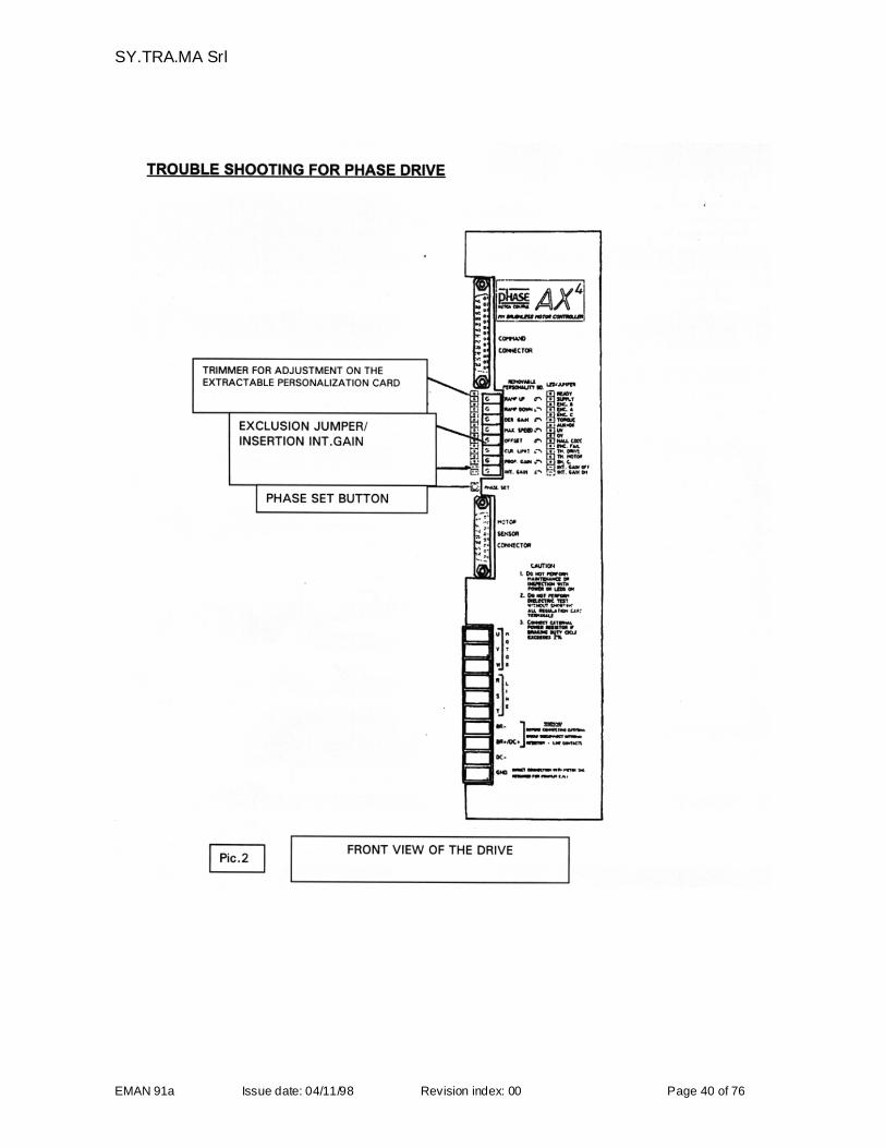
SY.TRA.MA normally fits PHASE drives (see Picture 22 on page 40).
PHASE drives have 14 different coloured diodes “LED” incorporated. The anomalies which may occur areindicated by different combinations of colours and positions which can be interpreted using the chart on page43 “DIAGNOSTIC FOR THE PHASE DRIVE” and page 41 “TROUBLE SHOOTING FOR PHASE DRIVE”.
ENCODER PHASING FOR PHASE DRIVE
In order to allow a correct functioning of the drive it is necessary that the encoder/sensors group with Halleffect mounted on the motor is located in a precise position considering the windings of the motor phases.Normally the encoder positioning, or phasing is carried out during the motor construction and therefore nointervention is required to the user. Anyway, should the encoder phasing control be necessary pleaseproceed as it follows:
Disengage the axis letting the motor free to rotate Supply the drive both for power and signal and enable the drive without reference, with a current control;
i.e. disconnect the wire PL1 (cur sel) of the axis from the terminal board XT3.
Press the button run aux of the control keyboard TME Press the button reset on the control keyboard TME Press the button Phase set and keep it pressed; the motor takes a direction and blocks itself. In this condition, if the encoder position is correct, one of the two led LD3-LD4 lights up and the other
one lights off. Manually forcing a light rotation, the motor shaft (always with the button Phase Setpressed) the lighting of the two led is inverted. Should the above happens the position of the encoder iscorrect and it is no more necessary any other phasing operation. If the position of the encoder is wrongproceed with the phasing operation as described in the following points.
Open the rear cap of the motor and loosen the screws of the encoder stator Manually rotate the encoder body observing the led LD3-LD4. Block the encoder in the position where the LED change their condition simultaneously screwing the
screws with a 0,2-0,5 Nm clamping torque and release the Phase Set button
Close the rear cap screwing the screw with a 5 Nm torque We suggest to carry out the phasing of the encoder with the highest possible care. The max acceptable
error is about 1 degree, equal to 0,5mm on the encoder perimeter.
1- Reconnect the wire PL1 (cur sel) in the terminal board XT32- Engage again the axis with the motor
ATTENTIONShould the encoder be re-installed or replaced, it might occur that the zero-point of the axis doesn’tcorrespond anymore to the original one. It is therefore necessary to check and/or modify the values in theTME keyboard.
NOTE 1: should the phasing be impossible, i.e. the motor does not rotate uniformly in the current loop, checkthe sequence of the motor phases and of the Hall ducts as shown in the electrical schemeNOTE 2: is, after the phasing, the motor operates regularly in the current loop but it presents a runway effectin the speed loop, check the sequence of the encoder signals A,B and C as shown in the electrical scheme.
SY.TRA.MA Srl
EMAN 91a Issue date: 04/11/98 Revision index: 00 Page 40 of 76
SY.TRA.MA Srl
EMAN 91a Issue date: 04/11/98 Revision index: 00 Page 41 of 76
TROUBLE SHOOTING FOR PHASE DRIVE
Here below are described all the precautions to be taken in case of alarm signal
The SUPPLY led is off
Check the presence of the feeding of the power circuit
The AUX=OK led is off
Check the presence of the auxiliary feeding
The TORQUE led is off
Check the presence of the activation command on the Command Connector
One of the led ENC A, ENC B, ENC C does not go on with the motor in rotation or remain always lit up.
Cut off the power, manually turn the motor shaft checking the presence of the signals of the Encoderchannels on the Motor Sensor Connector and their commutations.
The UV led is on
A voltage decrease on the bus DC has occurred. Check the value of the line voltage. The switching on ofthe led does not block continuously the drive, but the information is stored. In order to reset the alarm it isnecessary to cut off and give again the auxiliary voltage.If the under voltage condition remains for a period too long there is a discharge of the condenser on thebus in DC and the motor might stop. In this case it is necessary, once restored the correct networkvoltage, to disable the drive to make the re-start.For under voltage conditions over 2 ms the relay goes in alarm.
The OV led is on
An unforeseen increase of voltage has occurred on the DC bus. Check the value of the terminalresistance. The switching on of the led does not block continuously the drive, but the information isstored.
In order to reset the alarm it is necessary to cut off and give again the auxiliary voltage. For over voltage conditions over 2 ms the relay goes in alarm.
The HALL CODE led is on
The card has found a sequence error of the signals of the Hall sensor. Cut the power off, then, manuallyturning the motor shaft, check the presence of the signals of the sensor on the Motor Sensor Connector.The led switching on does not block continuously the drive, but the information is stored. In order to resetthe alarm it is necessary to cut off and give again the auxiliary voltage.
The ENC FAIL led is on
The card has found the missing of the encoder signal. Check the presence of all encoder signals, bothdirect and not allowed, on the Motor Sensor Connector. If all the signals are correct check theconnections to the ground.
SY.TRA.MA Srl
EMAN 91a Issue date: 04/11/98 Revision index: 00 Page 42 of 76
The SH C led in on
Short circuit indication in the wiring or anomaly in the cables or in the commutation. A part from the shortcircuit it can be activated by:
mass breakdown of the motor or the cableswrong encoder phasingmissing connection of the motor mass to the drive one, i.e. too long masses and of excessive impedanceradio electric interferences on the feeding or in the control panel
The TH Motor led (thermal motor) is on
the Encoder cable or its connector are faulty; replace the cable and/or the connector.
P.S.: should the alarm appear after some functioning hours, check the working cycle (duty cycle) and/orthe machine datas in the TME keyboard.
SY.TRA.MA Srl
EMAN 91a Issue date: 04/11/98 Revision index: 00 Page 43 of 76
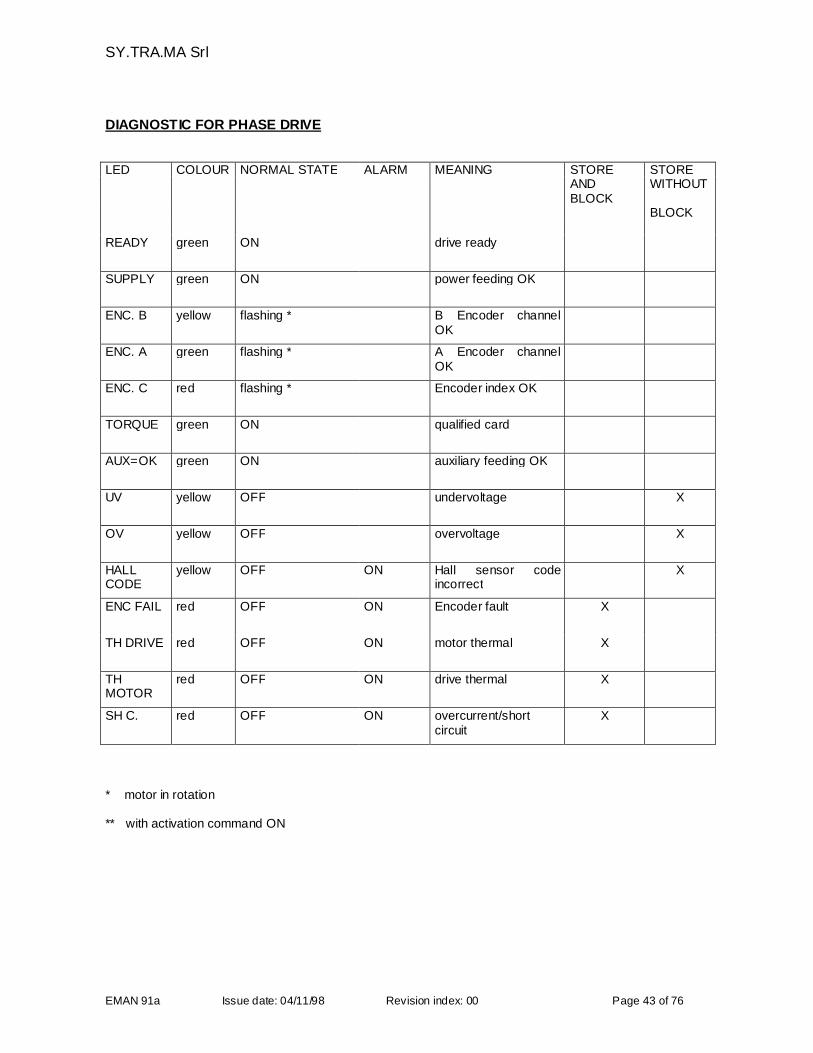
DIAGNOSTIC FOR PHASE DRIVE
LED COLOUR NORMAL STATE ALARM MEANING STORE STOREANDBLOCK
WITHOUT
BLOCK
READY green ON drive ready
SUPPLY green ON power feeding OK
ENC. B yellow flashing * B Encoder channelOK
ENC. A green flashing * A Encoder channelOK
ENC. C red flashing * Encoder index OK
TORQUE green ON qualified card
AUX=OK green ON auxiliary feeding OK
UV yellow OFF undervoltage X
OV yellow OFF overvoltage X
HALLCODE
yellow OFF ON Hall sensor codeincorrect
X
ENC FAIL red OFF ON Encoder fault X
TH DRIVE red OFF ON motor thermal X
THMOTOR
red OFF ON drive thermal X
SH C. red OFF ON overcurrent/shortcircuit
X
* motor in rotation
** with activation command ON
SY.TRA.MA Srl
EMAN 91a Issue date: 04/11/98 Revision index: 00 Page 44 of 76
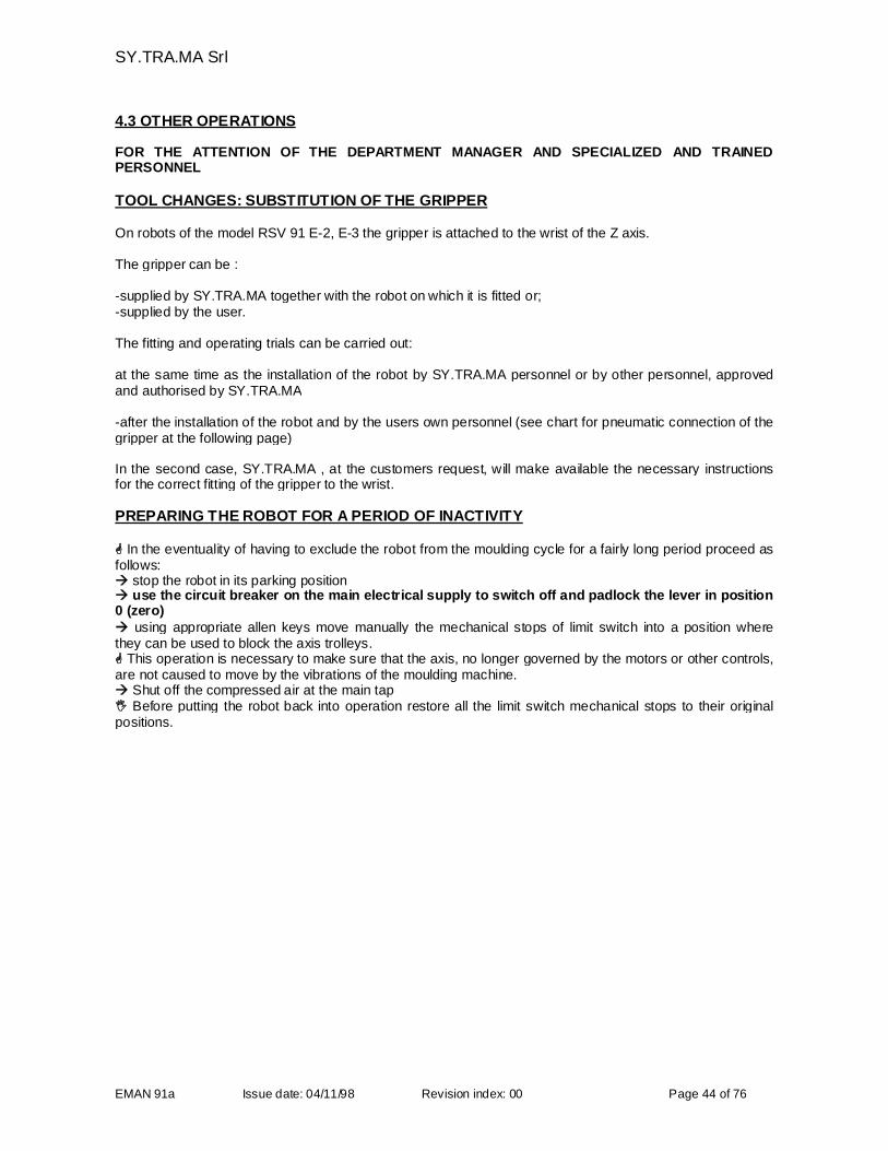
4.3 OTHER OPERATIONS
FOR THE ATTENTION OF THE DEPARTMENT MANAGER AND SPECIALIZED AND TRAINEDPERSONNEL
TOOL CHANGES: SUBSTITUTION OF THE GRIPPER
On robots of the model RSV 91 E-2, E-3 the gripper is attached to the wrist of the Z axis.
The gripper can be :
-supplied by SY.TRA.MA together with the robot on which it is fitted or;-supplied by the user.
The fitting and operating trials can be carried out:
at the same time as the installation of the robot by SY.TRA.MA personnel or by other personnel, approvedand authorised by SY.TRA.MA
-after the installation of the robot and by the users own personnel (see chart for pneumatic connection of thegripper at the following page)
In the second case, SY.TRA.MA , at the customers request, will make available the necessary instructionsfor the correct fitting of the gripper to the wrist.
PREPARING THE ROBOT FOR A PERIOD OF INACTIVITY
In the eventuality of having to exclude the robot from the moulding cycle for a fairly long period proceed asfollows: stop the robot in its parking position use the circuit breaker on the main electrical supply to switch off and padlock the lever in position0 (zero) using appropriate allen keys move manually the mechanical stops of limit switch into a position wherethey can be used to block the axis trolleys. This operation is necessary to make sure that the axis, no longer governed by the motors or other controls,are not caused to move by the vibrations of the moulding machine. Shut off the compressed air at the main tap Before putting the robot back into operation restore all the limit switch mechanical stops to their originalpositions.
SY.TRA.MA Srl
EMAN 91a Issue date: 04/11/98 Revision index: 00 Page 45 of 76
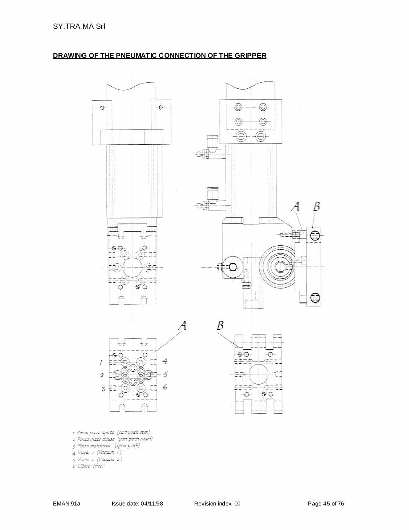
DRAWING OF THE PNEUMATIC CONNECTION OF THE GRIPPER
SY.TRA.MA Srl
EMAN 91a Issue date: 04/11/98 Revision index: 00 Page 46 of 76
STORING THE ROBOT
If the equipment cannot be installed for a long period after delivery of if it has to be put into store, the parts intheir original packing may be stored for up to a year in a covered area provided that the temperature andhumidity levels remain within the limits specified at under the heading "DIMENSIONS AND TECHNICALCHARACTERISTICS".
If the robot has already been in service and has to be mothballed for a period proceed as follows:
Proceed: carefully clean the various elements of the machine with detergents which do not corrode the painted
parts; lubricate the guide bars of the three axis with SAE 46-SAE 68 oil; lubricate the worm screw with molybdenum bisulphide grease; cover the whole plant with waterproof sheeting to protect it from possible leaks in the roof and/or othersubstances that could cause deterioration.
No other material must be stored on top of the mothballed plant.
START UP AFTER STORAGE PERIOD
After a prolonged period of storage, as with the normal or initial start up, the plant should be put intooperation by a SY.TRA.MA technician or, in any case by personnel approved and authorised bySY.TRA.MA. Before the arrival of the technician check that:
- the machine is in the same state and condition as it was at the beginning of the storage period;- the structure has not suffered deterioration due to corrosion;- the electrical contacts are in good working order and that no cables are broken;- all of the safety devices, when tested by hand, work efficiently.
These checks serve to identify any material that may need to be replaced so that the technician mayperform the start up with all the necessary material available.
Whenever the plant remains disconnected from the electric feeding for more than three (3) years from theelectric feeding, also depending on the room temperature (with a new lithium battery) the back up battery forthe Random Access Memory in the control panel must be replaced.
SY.TRA.MA Srl
EMAN 91a Issue date: 04/11/98 Revision index: 00 Page 47 of 76
5. MAINTENANCE INSTRUCTIONS
5.1 MAINTENANCE
FOR THE ATTENTION OF THE DEPARTMENT MANAGER
The maintenance programm includes checking, inspection and control operations to be carried out by themachine operator and/or the specialised personnel of the maintenance staff and periodic controls whichinclude examination, calibration and substitutions to be carried out by specialised personnel who havespecifically trained by SY.TRA.MA . To help carry out these operations the trained specialist has at hisdisposal:
- supporting information provided by the diagnosis programs for the electrical-electronic system- exploded view drawings to understand the structure of the mechanical components.
ATTENTION: In order to work under safety conditions during the maintenance procedures of therobot and / or of the machines connected to the same, it is absolutely necessary to move the verticalaxis downwards up to the mechanical ledge, avoiding in this way any potential and remaining risk.
5.2 PARTICULAR UNPLANNED MAINTENANCE OPERATIONS
FOR THE ATTENTION OF SPECIALIZED AND TRAINED PERSONNEL
CONTROL INTERVENTION AFTER A MECHANICAL CRASH
If during th life of the robot, after any fault, one or more axes beat against the other mechanical parts oragainst the limit switch stopper it is necessary to: check the stoppers/rubber shock abosorber check the screwing and/or stretching of the screws interested in the problems caused by the crash check the belts and worm screws check that some damage has been cause to the guides and the other mechanical parts

SY.TRA.MA Srl
EMAN 91a Issue date: 04/11/98 Revision index: 00 Page 48 of 76
PROCEDURE FOR CHANGING THE BATTERY
FOR THE ATTENTION OF SPECIALIZED AND TRAINED PERSONNEL
In ideal working conditions the PLC backup batteries can be expected to last for almost 5 (five) years.In reality a number of factors such as variations in working temperature and intervals of varying length inwhich the control panel is not switched on make it difficult to fix a set period for the replacement of thebattery.
The battery self-dechargement value is approx 5% per year (c.ca). This figure is to be reffered to a roomtemperature of 25° C. Sould the room temperature be 40°c, this would reduce the a.m. value.
The control indicates that the battery needs replacing
SY.TRA.MA recommends that, in the context of a preventative maintenance programme, usersestablish an interval period for the replacement of the batteries no longer than 3 (three) years. This toavoid surely the possible problems connected to their functioning.
ATTENTION: independent from the operative mode it is possible to change the battery withoutloosing the datas, if the feeding to the PLC remains activated; otherwise before replacing the battery,save the stored datas (user program and machine datas) using the programming/back-up unit and/orprinter, otherwise manually overwrite everyting.
One 3,0V standard lithium battery not reachargeable is used. Type : CR 2032 (IEC); we suggest you to useprofessional batteries with minimum capacity of 200 m Ah, e.g:
RENATA Code: 4'507’4817’0
SY.TRA.MA Srl
EMAN 91a Issue date: 04/11/98 Revision index: 00 Page 49 of 76
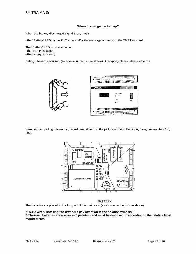
When to change the battery?
When the battery discharged signal is on, that is:
- the "Battery" LED on the PLC is on and/or the message appears on the TME keyboard.
The “Battery” LED is on even when:- the battery is faulty- the battery is missing
pulling it towards yourself, (as shown in the picture above). The spring clamp releases the top.
Remove the , pulling it towards yourself, (as shown on the picture above): The spring fixing makes the o’ringfree.
BATTERY
The batteries are placed in the low part of the main card (as shown on the picture above).
N.B.: when installing the new cells pay attention to the polarity symbols !The used batteries are a source of pollution and must be disposed of according to the relative legalrequirements
SY.TRA.MA Srl
EMAN 91a Issue date: 04/11/98 Revision index: 00 Page 50 of 76
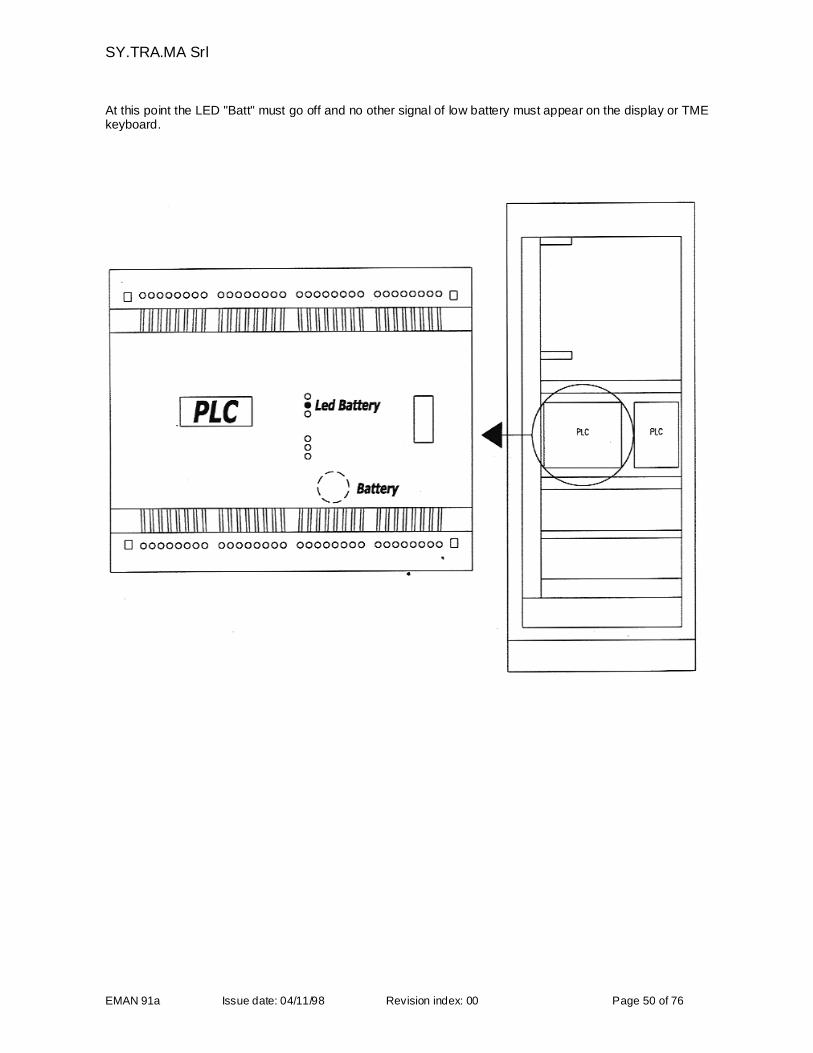
At this point the LED "Batt" must go off and no other signal of low battery must appear on the display or TMEkeyboard.
SY.TRA.MA Srl
EMAN 91a Issue date: 04/11/98 Revision index: 00 Page 51 of 76
5.3 ROUTINE MAINTENANCE
Includes the maintenance operations which can be carried out by either the operator himself or byspecialized maintenance staff according to the indications given in the present document and which do notrequire the use of particular instruments or tools.
DAILY OPERATIONS TO BE PERFORMED BY THE OPERATOR
Before introducing the robot into the operating cycle :
-carry out a visual control of the plant-run a check of all the limit switches overstrokes, push button operations, safety guards work and check theemergency stop buttons.
WEEKLY OPERATIONS TO BE PERFORMED BY THE OPERATOR AND/OR SPECIALIZEDMAINTENANCE STAFF
Once a week :
-use a dry cloth to clean the whole plant to prevent dirt accumulating between the drive mechanisms of themoving parts;-clean the suction cups of the gripper using methylated spirit- clean the ventilator filters on the control panel. This last operation is important to ensure that all the elements inside the panel work with the maximumefficiency.It must be effected using a blow of dry compressed air working from the inside of the panel towards theoutside, if you are in any doubt as to the efficiency of the filter change it straightaway.- lubricate the worm screw and scroll (X electrical axis)- lubricate the axis sliding blocks We recommend particular care when cleaning the translation bars of the three axis to ensure that dirt doesnot accumulate between the sliding blocks which could block the bearings and score the bars. (Avoid usingcorrosive liquids which could damage the scrapers.)After having cleaned the bars, lubricate the sliding blocks by means of the proper graiser. We suggest graiseN2 based on lithium soap, while in case of lubrication with oil it is better to use ISO VG32/68 oil orequivalent.
- check that the safety devices of the guards, the emergency buttons, the mechanical stops on the limitswitches and the push button control unit are working efficiently.- carry out a visual control of the state of the cables and leads which are not covered. Before undertaking any of these maintenance operations it is absolutely necessary to disconnectthe main power supply and to attach a " MAINTENANCE IN COURSE ON THIS MACHINE" warningsign to the equipment.
5.4 PLANNED PERIODIC MAINTENANCE
This includes those operations and checks which may involve the need to adjust and/or replace certaincomponents and must be carried out by specialised personnel who have been specifically trained forthese tasks.
We emphasise the necessity to observe rigidly the intervals defined in the "PLANNED MAINTENANCETIME TABLE " included in this section of the manual. During these maintenance operations make full use of the exploded view drawings for the mechanicalitems, of the diagnosis programs and of the wiring diagrams for the electric and electronic components.
SY.TRA.MA Srl
EMAN 91a Issue date: 04/11/98 Revision index: 00 Page 52 of 76
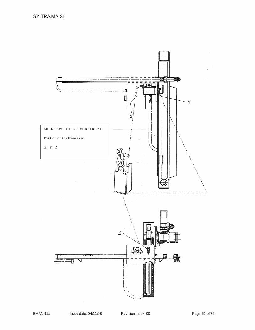
MICROSWITCH - OVERSTROKE
Position on the three axes
X Y Z
SY.TRA.MA Srl
EMAN 91a Issue date: 04/11/98 Revision index: 00 Page 53 of 76
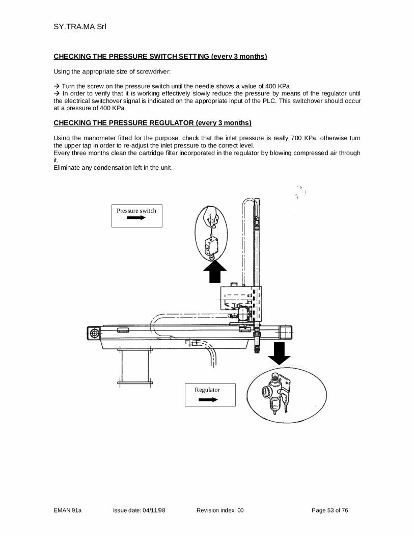
CHECKING THE PRESSURE SWITCH SETTING (every 3 months)
Using the appropriate size of screwdriver:
Turn the screw on the pressure switch until the needle shows a value of 400 KPa. In order to verify that it is working effectively slowly reduce the pressure by means of the regulator untilthe electrical switchover signal is indicated on the appropriate input of the PLC. This switchover should occurat a pressure of 400 KPa.
CHECKING THE PRESSURE REGULATOR (every 3 months)
Using the manometer fitted for the purpose, check that the inlet pressure is really 700 KPa, otherwise turnthe upper tap in order to re-adjust the inlet pressure to the correct level.Every three months clean the cartridge filter incorporated in the regulator by blowing compressed air throughit.Eliminate any condensation left in the unit.
Regulator
Pressure switch
SY.TRA.MA Srl
EMAN 91a Issue date: 04/11/98 Revision index: 00 Page 54 of 76
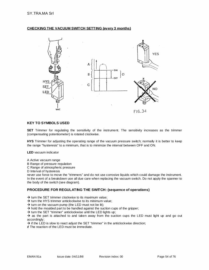
CHECKING THE VACUUM SWITCH SETTING (every 3 months)
KEY TO SYMBOLS USED
SET Trimmer for regulating the sensitivity of the instrument. The sensitivity increases as the trimmer(compensating potentiometer) is rotated clockwise.
HYS Trimmer for adjusting the operating range of the vacuum pressure switch; normally it is better to keep
the range "hysteresis" to a minimum, that is to minimize the interval between OFF and ON.
LED vacuum indicator
A Active vacuum rangeB Range of pressure regulationC Range of atmospheric pressureD Interval of hysteresisnever use force to move the “trimmers” and do not use corrosive liquids which could damage the instrument.In the event of a breakdown use all due care when replacing the vacuum switch. Do not apply the spanner tothe body of the switch (see diagram).
PROCEDURE FOR REGULATING THE SWITCH: (sequence of operations)
turn the SET trimmer clockwise to its maximum value; turn the HYS trimmer anticlockwise to its minimum value; turn on the vacuum pump (the LED must not be lit); hold the moulded part to be handled against the suction cups of the gripper; turn the SET “trimmer” anticlockwise until the LED lights up; as the part is attached to and taken away from the suction cups the LED must light up and go outaccordingly; if the LED is slow to react adjust the SET “trimmer” in the anticlockwise direction; The reaction of the LED must be immediate.
YES
SY.TRA.MA Srl
EMAN 91a Issue date: 04/11/98 Revision index: 00 Page 55 of 76
CHECKING THE TRANSLATION BARS OF THE AXIS (every 3 months)
Every three months check that:
- the bars show no sign of scoring;- the noise is within such a limit that it does not indicate a sign of deterioration of the sliding blocks;- the cleaning of the sliding blocks, bars and worm screw (for electrical X) are being duly performed;If the bars show the minimum sign of wear replace the bars and the sliding blocks.
CHECKING THE GEAR REDUCTION UNITS (every 3 months)
Check that there is not sign of oli loss. The reduction units fitted on our series 91 robots are oiled “for life” innormal working conditions. It is important to check that there is no evident play between the unit and thetransmission cogs. Otherwise replace the coupling spline.Should there be the need to fill up the oil, following disassembly or leaks, you have to use the followinglubricants or compatible:
SUGGESTED OILSMobil Mobilgear SHC 220BP Energol GR-XP 220Kluber Klubersynth GEM 4 220Shell Omala oil RL220Agip Blasia SX 220
The quantity or the lubricating liquid contained in the SP100 gear-box is 0,1 l.
CHECKING THE TOOTHED BELTS (every 3 months)
Check that the teeth are in good condition and that there are no signs of tearing or stripping at the borders. Ifany damage is noted, even to a single tooth, replace the belt immediately.
CHECKING THE SCROLL – WORM SCRUE OF X AXIS (every 3 months)
Check the correct coupling and noise. Check that the lubrication of the sworm screw is done regurarly withgraise based on lithium soap which must have a viscosity of 32-14 Cst at 40°C, for example Shell AV2 orKluber Isoflex LDS18.
CHECKING THE CYLINDERS (every 3 months)
Check that the cylinders are correctly anchored to the structural parts of the axis and check that they areclean and in good working order. Lubricate the shaft with a cloth impregnate of oil with low viscosity.
SY.TRA.MA Srl
EMAN 91a Issue date: 04/11/98 Revision index: 00 Page 56 of 76
CHECKING THE LUBRICATION OF BARS AND SLIDING BLOCKS (every week)
Check that the lubrication of the bars and of the sliding blocks is made with graise soap lithium.
CHECKING THE TIGHTNESS OF THE BOLTS (every 3 months)
Check the correct torque wrench setting of the bolts:
- between the the support and the moulding machine platen- between the robot and the support
Refer to the "CHART OF THE TORSION VALUES FOR BLOCKING CLASS 8.8 SET SCREWS" on page 28. It is possible that some bolts on other elements of the robot not directly related to the safety of theequipment tend to slacken as a result of the moulding machine vibrations, these should all be checked andtightened where necessary.
CHECKING THE LEADS, CONNECTIONS, CABLES PUSH BUTTONS AND THEELECTRICAL SAFETY DEVICES (every 3 months)
Carry out a check of all these elements and take particular care to check that all the safety devices are fixedfirmly in position
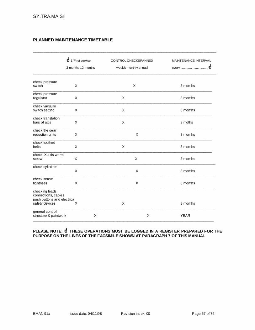
SY.TRA.MA Srl
EMAN 91a Issue date: 04/11/98 Revision index: 00 Page 57 of 76
PLANNED MAINTENANCE TIMETABLE
______________________________________________________________________
1°First service CONTROL CHECKSPANNED MAINTENANCE INTERVAL
3 months 12 months weekly monthly annual every.................................______________________________________________________________________
check pressureswitch X X 3 months___________________________________________________________________________________________check pressureregulator X X 3 months___________________________________________________________________________________________check vacuumswitch setting X X 3 months___________________________________________________________________________________________check translationbars of axis X X 3 moths___________________________________________________________________________________________check the gearreduction units X X 3 months___________________________________________________________________________________________check toothedbelts X X 3 months___________________________________________________________________________________________check X axis wormscrew X X 3 months_____________________________________________________________________________________________check cylinders
X X 3 months____________________________________________________________________________________________check screwtightness X X 3 months____________________________________________________________________________________________checking leads,connections, cablespush buttons and electricalsafety devices X X 3 months____________________________________________________________________________________________general controlstructure & paintwork X X YEAR____________________________________________________________________________________________
PLEASE NOTE: THESE OPERATIONS MUST BE LOGGED IN A REGISTER PREPARED FOR THEPURPOSE ON THE LINES OF THE FACSIMILE SHOWN AT PARAGRAPH 7 OF THIS MANUAL
SY.TRA.MA Srl
EMAN 91a Issue date: 04/11/98 Revision index: 00 Page 58 of 76
5.5 DISMOUNTING THE ROBOT
If for whatever reason there is a need to remove the robot from its working position above themoulding machine the following procedure should be followed.
PROCEDURE FOR DISMOUNTING THE ROBOT
Prepare the working area with suitable warning signs; make available a suitable lifting apparatus.
Shut off the power supply by disconnecting the main switch disconnect the pneumatic supply disconnect the power cables, the interface and all the connecting leads between the panel and the robot. We emphasize the need to follow to the letter the procedure for slinging the equipment as described underthe heading "HOISTING AND FIXING THE ROBOT" (see also chapter 3.2).Once the axis have been blocked and with the weight of the robot supported by the straps: slacken all the set screws which anchor the robot to the support check that the slung mass is in equilibrium remove the slackened screws lift the robot off the support and lower it to just above ground level attach the transport brackets under the Y axis beam and lower gently to the ground Consult the instructions for the correct method of slinging the support frame that are given under theheading "HOISTING AND FIXING THE SUPPORT FRAME" (see also chapter 3.2).
Unscrew all the screws anchoring the support to the fixed platen of the moulding machine Hoist the support and lower it gently onto a pallet
5.6 SCRAPPING AND DISPOSAL
In the eventuality of a decision to scrap the equipment, the main structure and the panel must be takenapart in order to separate out all materials which may contaminate the environment; the robot contains noparts or components which constitute an active risk during the disassembly operations.
Recover the oil from the reduction units Remove the belts and the components made of plastic and gum Strip all components from the panel which contain, even in small quantities, materials which are known tobe pollutive: e.g. cables, sheathing, switches, buttons, solenoid starters, back up batteries, etc. Remember not to abandon any material in the environment but to entrust the disposal only to specializedand authorised waste disposal organisations and/or to specially designated centres for the collection ofcontaminating substances.
SY.TRA.MA Srl
EMAN 91a Issue date: 04/11/98 Revision index: 00 Page 59 of 76
6. SPARE PARTS
SY.TRA.MA robots are designed and manufactured in such a manner as not to require, if used correctly andmaintained in accordance with the instructions given in this manual, replacement of components as a resultof wear and tear.Where the breakdown or failure of components renders the substitution necessary it is obligatory to useonly original spare parts to be ordered directly from SY.TRA.MA.The use of non original spare parts, apart from nullifying the guarantee, may prejudice the correctworking of the equipment.
6.1 IDENTIFYING SPARE PARTS PAGES FOR MODELS 91 E-2,E-3
When ordering spare parts indicate clearly:- Machine model and serial number.- Order confirmation number and the date of delivery.- Drawing number which appears on the top of the parts list in which the item is found.- Part number and description of the article.- Quantity required.
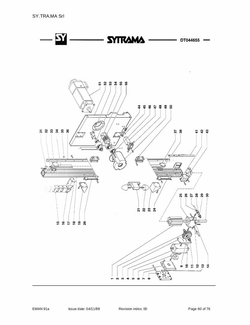
SY.TRA.MA Srl
EMAN 91a Issue date: 04/11/98 Revision index: 00 Page 60 of 76
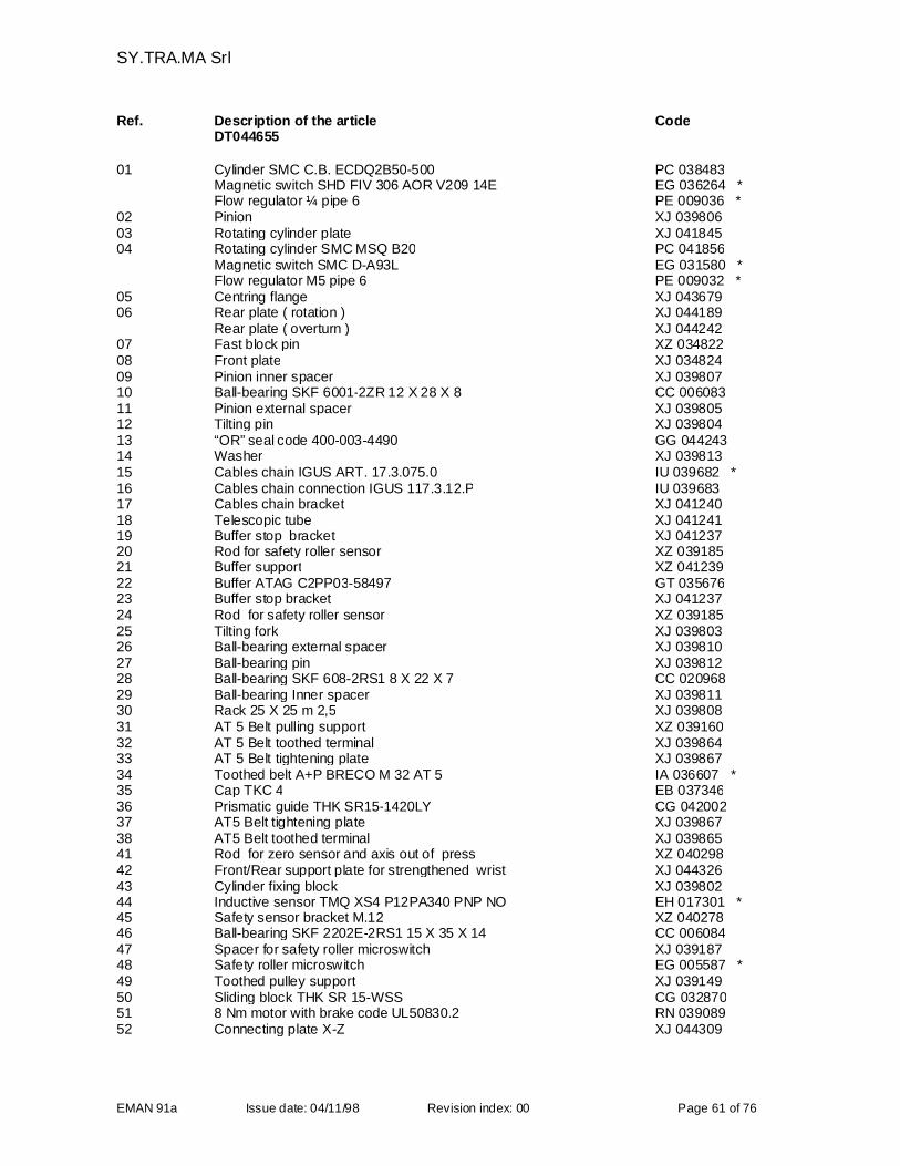
SY.TRA.MA Srl
EMAN 91a Issue date: 04/11/98 Revision index: 00 Page 61 of 76
Ref. Description of the article CodeDT044655
01 Cylinder SMC C.B. ECDQ2B50-500 PC 038483Magnetic switch SHD FIV 306 AOR V209 14E EG 036264 *Flow regulator ¼ pipe 6 PE 009036 *
02 Pinion XJ 03980603 Rotating cylinder plate XJ 04184504 Rotating cylinder SMC MSQ B20 PC 041856
Magnetic switch SMC D-A93L EG 031580 *Flow regulator M5 pipe 6 PE 009032 *
05 Centring flange XJ 04367906 Rear plate ( rotation ) XJ 044189
Rear plate ( overturn ) XJ 04424207 Fast block pin XZ 03482208 Front plate XJ 03482409 Pinion inner spacer XJ 03980710 Ball-bearing SKF 6001-2ZR 12 X 28 X 8 CC 00608311 Pinion external spacer XJ 03980512 Tilting pin XJ 03980413 “OR” seal code 400-003-4490 GG 04424314 Washer XJ 03981315 Cables chain IGUS ART. 17.3.075.0 IU 039682 *16 Cables chain connection IGUS 117.3.12.P IU 03968317 Cables chain bracket XJ 04124018 Telescopic tube XJ 04124119 Buffer stop bracket XJ 04123720 Rod for safety roller sensor XZ 03918521 Buffer support XZ 04123922 Buffer ATAG C2PP03-58497 GT 03567623 Buffer stop bracket XJ 04123724 Rod for safety roller sensor XZ 03918525 Tilting fork XJ 03980326 Ball-bearing external spacer XJ 03981027 Ball-bearing pin XJ 03981228 Ball-bearing SKF 608-2RS1 8 X 22 X 7 CC 02096829 Ball-bearing Inner spacer XJ 03981130 Rack 25 X 25 m 2,5 XJ 03980831 AT 5 Belt pulling support XZ 03916032 AT 5 Belt toothed terminal XJ 03986433 AT 5 Belt tightening plate XJ 03986734 Toothed belt A+P BRECO M 32 AT 5 IA 036607 *35 Cap TKC 4 EB 03734636 Prismatic guide THK SR15-1420LY CG 04200237 AT5 Belt tightening plate XJ 03986738 AT5 Belt toothed terminal XJ 03986541 Rod for zero sensor and axis out of press XZ 04029842 Front/Rear support plate for strengthened wrist XJ 04432643 Cylinder fixing block XJ 03980244 Inductive sensor TMQ XS4 P12PA340 PNP NO EH 017301 *45 Safety sensor bracket M.12 XZ 04027846 Ball-bearing SKF 2202E-2RS1 15 X 35 X 14 CC 00608447 Spacer for safety roller microswitch XJ 03918748 Safety roller microswitch EG 005587 *49 Toothed pulley support XJ 03914950 Sliding block THK SR 15-WSS CG 03287051 8 Nm motor with brake code UL50830.2 RN 03908952 Connecting plate X-Z XJ 044309
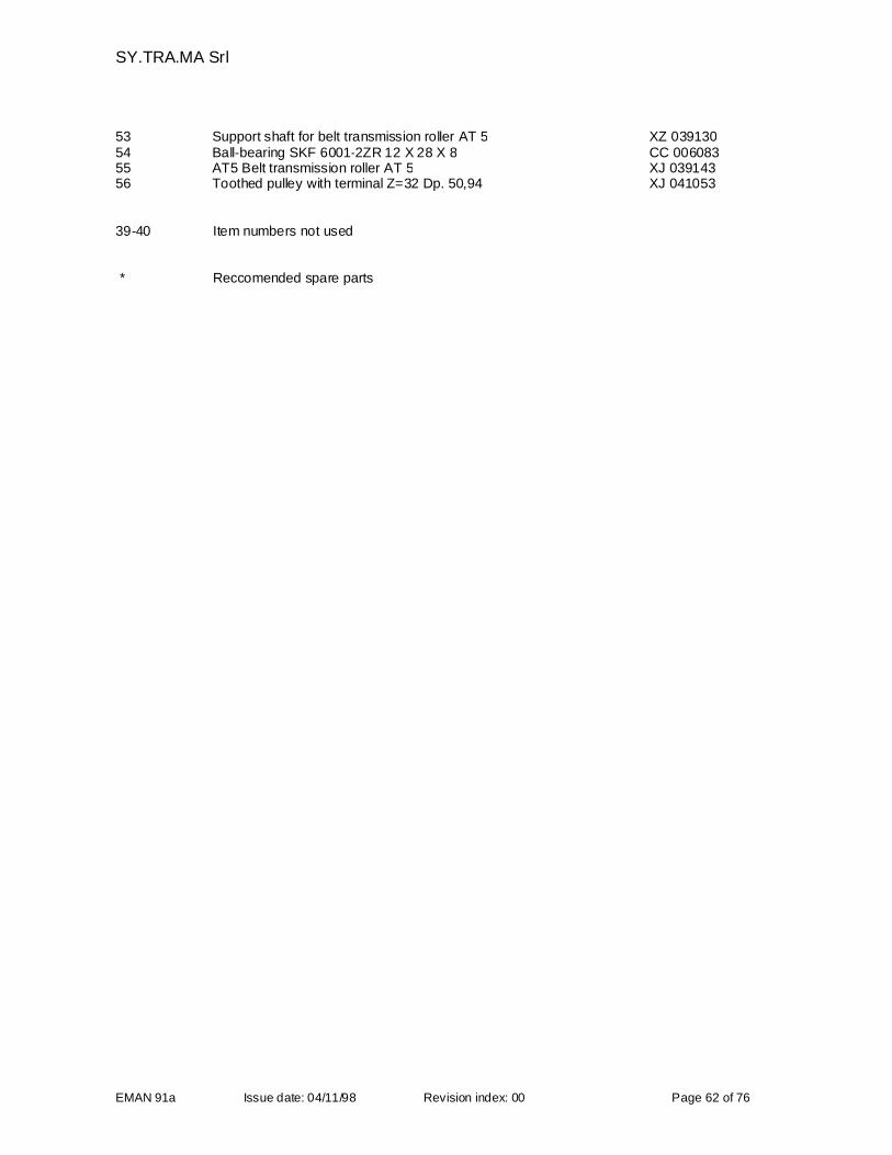
SY.TRA.MA Srl
EMAN 91a Issue date: 04/11/98 Revision index: 00 Page 62 of 76
53 Support shaft for belt transmission roller AT 5 XZ 03913054 Ball-bearing SKF 6001-2ZR 12 X 28 X 8 CC 00608355 AT5 Belt transmission roller AT 5 XJ 03914356 Toothed pulley with terminal Z=32 Dp. 50,94 XJ 041053
39-40 Item numbers not used
* Reccomended spare parts
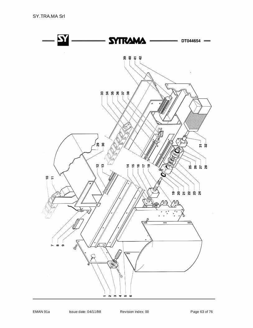
SY.TRA.MA Srl
EMAN 91a Issue date: 04/11/98 Revision index: 00 Page 63 of 76
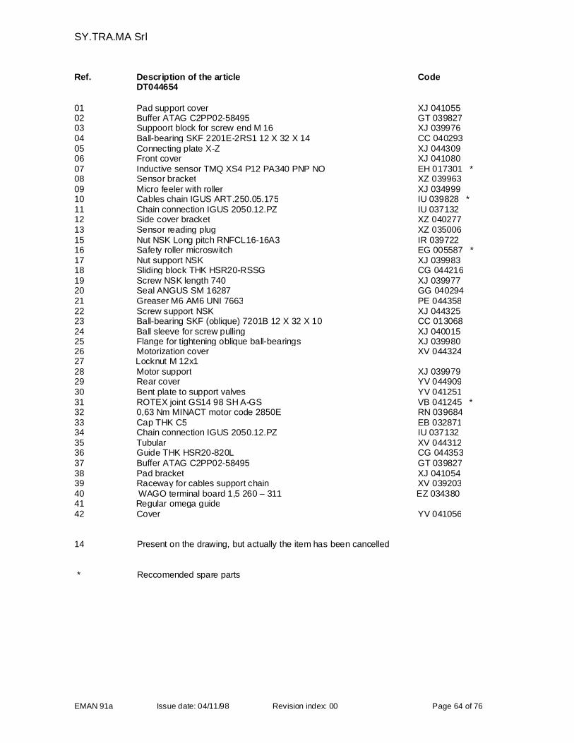
SY.TRA.MA Srl
EMAN 91a Issue date: 04/11/98 Revision index: 00 Page 64 of 76
Ref. Description of the article CodeDT044654
01 Pad support cover XJ 04105502 Buffer ATAG C2PP02-58495 GT 03982703 Suppoort block for screw end M 16 XJ 03997604 Ball-bearing SKF 2201E-2RS1 12 X 32 X 14 CC 04029305 Connecting plate X-Z XJ 04430906 Front cover XJ 04108007 Inductive sensor TMQ XS4 P12 PA340 PNP NO EH 017301 *08 Sensor bracket XZ 03996309 Micro feeler with roller XJ 03499910 Cables chain IGUS ART.250.05.175 IU 039828 *11 Chain connection IGUS 2050.12.PZ IU 03713212 Side cover bracket XZ 04027713 Sensor reading plug XZ 03500615 Nut NSK Long pitch RNFCL16-16A3 IR 03972216 Safety roller microswitch EG 005587 *17 Nut support NSK XJ 03998318 Sliding block THK HSR20-RSSG CG 04421619 Screw NSK length 740 XJ 03997720 Seal ANGUS SM 16287 GG 04029421 Greaser M6 AM6 UNI 7663 PE 04435822 Screw support NSK XJ 04432523 Ball-bearing SKF (oblique) 7201B 12 X 32 X 10 CC 01306824 Ball sleeve for screw pulling XJ 04001525 Flange for tightening oblique ball-bearings XJ 03998026 Motorization cover XV 04432427 Locknut M 12x128 Motor support XJ 03997929 Rear cover YV 04490930 Bent plate to support valves YV 04125131 ROTEX joint GS14 98 SH A-GS VB 041245 *32 0,63 Nm MINACT motor code 2850E RN 03968433 Cap THK C5 EB 03287134 Chain connection IGUS 2050.12.PZ IU 03713235 Tubular XV 04431236 Guide THK HSR20-820L CG 04435337 Buffer ATAG C2PP02-58495 GT 03982738 Pad bracket XJ 04105439 Raceway for cables support chain XV 03920340 WAGO terminal board 1,5 260 – 311 EZ 03438041 Regular omega guide42 Cover YV 041056
14 Present on the drawing, but actually the item has been cancelled
* Reccomended spare parts
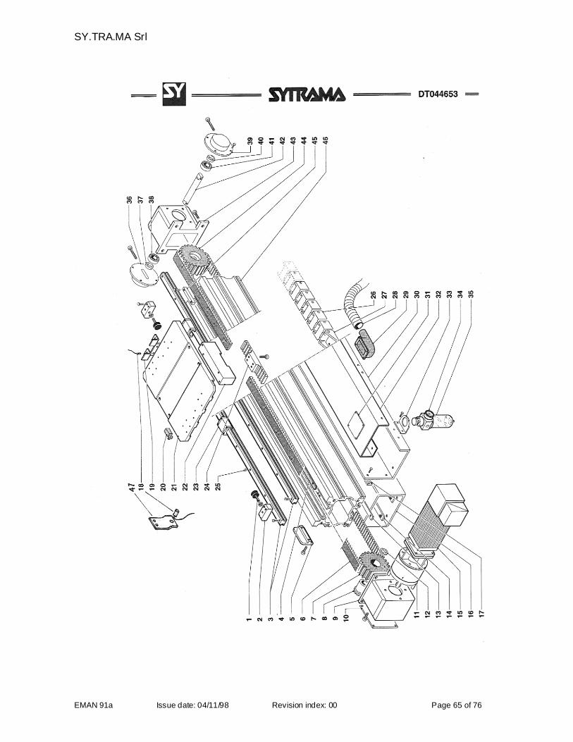
SY.TRA.MA Srl
EMAN 91a Issue date: 04/11/98 Revision index: 00 Page 65 of 76
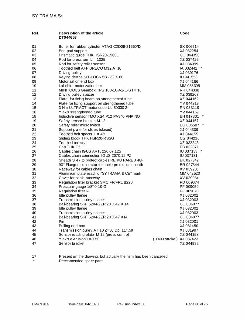
SY.TRA.MA Srl
EMAN 91a Issue date: 04/11/98 Revision index: 00 Page 66 of 76
Ref. Description of the article CodeDT044653
01 Buffer for rubber cylinder ATAG C2D08-31660/D SX 00651402 End pad support XJ 03225403 Prismatic guide THK HSR20-1960L CG 04435004 Rod for press arm L = 1025 XZ 03742605 Rod for safety roller sensor XJ 03499906 Toothed belt A+P BRECO M32 AT10 IA 032442 *07 Driving pulley XJ 03917608 Keying device SIT-LOCK 5B - 32 X 60 ID 04155309 Motorization end box XJ 04416610 Label for motorization box MM 03539511 MINITOOLS Gearbox HPS 100-10-A1-C-S I = 10 RR 04433812 Driving pulley spacer XZ 03920713 Plate for fixing beam on strengthened tube XZ 04416214 Plate for fixing support on strengthened tube YV 04421815 3 Nm ULTRACT motor code UL 50330.2 RN 03311916 Y axis strengthened tube YV 04415918 Inductive sensor TMQ XS4 P12 PA340 PNP NO EH 017301 *19 Safety sensor bracket M.12 XZ 04415720 Safety roller microswitch EG 005587 *21 Support plate for slides (closed) XJ 04430922 Toothed belt spacer H = 48 XJ 04415523 Sliding block THK HSR20-RSSG CG 04421624 Toothed terminal XZ 03224825 Cap THK C5 EB 03287126 Cables chain IGUS ART. 250.07.125 IU 037133 *27 Cables chain connection IGUS 2070.12.PZ IU 03713128 Sheath 47 to protect cables REIKU PAREB 48F EK 02734229 90° Flanged connector for cable protection sheath ER 02734430 Raceway for cables chain XV 03920531 Aluminium plate reading “SYTRAMA & CE” mark MM 04252032 Cover for cable raceway XV 03993433 Regulation filter bracket SMC FR/FRL B220 PD 00907434 Pressure-gauge 1/8” 0-10-G PF 00905935 Regulation filter ¼ PF 00907036 Idle pulley flange XJ 03200237 Transmission pulley spacer XJ 03200338 Ball-bearing SKF 6204-2ZR 20 X 47 X 14 CC 00607739 Idle pulley flange XJ 03200240 Transmission pulley spacer XJ 03200341 Ball-bearing SKF 6204-2ZR 20 X 47 X14 CC 00607742 Pin XJ 03200143 Pulling end box XJ 03145044 Transmission pulley AT 10 Z=36 Dp. 114.59 XJ 03199745 Sensor reading plate M.12 (press centre) XZ 04415846 Y axis extrusion L=2050 ( 1400 stroke ) XJ 03742347 Sensor bracket XZ 044938
17 Present on the drawing, but actually the item has been cancelled* Reccomended spare parts
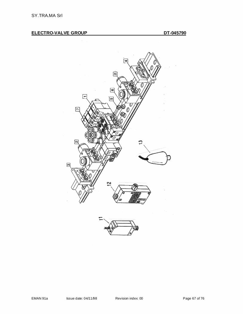
SY.TRA.MA Srl
EMAN 91a Issue date: 04/11/98 Revision index: 00 Page 67 of 76
ELECTRO-VALVE GROUP DT-045790
SY.TRA.MA Srl
EMAN 91a Issue date: 04/11/98 Revision index: 00 Page 68 of 76
ELECTRO-VALVE GROUPDT045790
Ref. Description of the article Code
1 Simple electro-valve SMC SY 3160-5LOU-C6F M5 PV 044272 *
1 Connector SMC SY 100-30-4A-10 PV 038012 *
2 Drive P/R SY 3000-55-1A PV 044274
3 End module side D SY3000-56-1A PV 044275
4 End module side U SY3000-56-1B PV 044276
5 Junction bush SY3000-52-1A PV 044277 *
6 Regular omega guide
7 Double electro-valve SMC SY3260-5-LOU-C6F-M5 PV044273 *
11 Vacuum Switch SMC EZSE1-01-55L PG009069 *
12 Venturi SMC EZH10BS-06-F01 PG009131
13 Pressure Switch PG035075
8-9-10 Item numbers not used
* Reccomended spare parts
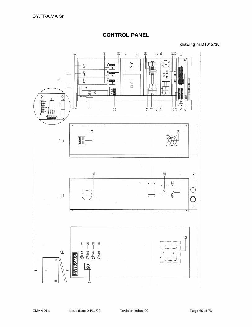
SY.TRA.MA Srl
EMAN 91a Issue date: 04/11/98 Revision index: 00 Page 69 of 76
CONTROL PANEL
drawing nr.DT045730
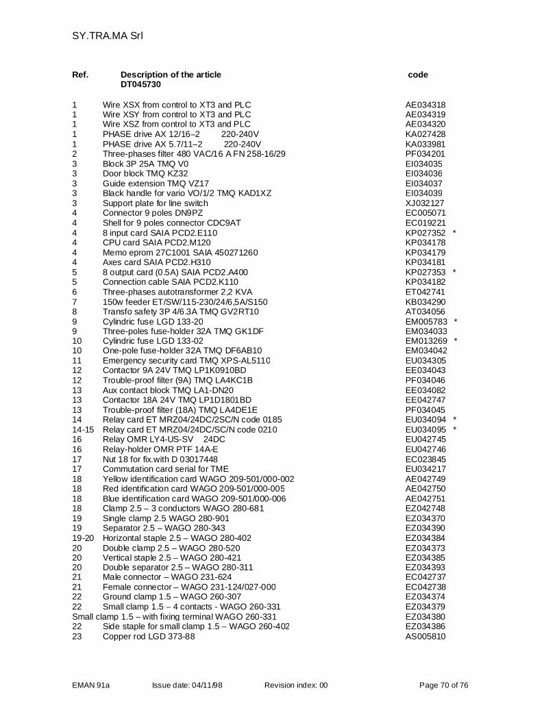
SY.TRA.MA Srl
EMAN 91a Issue date: 04/11/98 Revision index: 00 Page 70 of 76
Ref. Description of the article codeDT045730
1 Wire XSX from control to XT3 and PLC AE0343181 Wire XSY from control to XT3 and PLC AE0343191 Wire XSZ from control to XT3 and PLC AE0343201 PHASE drive AX 12/16–2 220-240V KA0274281 PHASE drive AX 5.7/11–2 220-240V KA0339812 Three-phases filter 480 VAC/16 A FN 258-16/29 PF0342013 Block 3P 25A TMQ V0 EI0340353 Door block TMQ KZ32 EI0340363 Guide extension TMQ VZ17 EI0340373 Black handle for vario VO/1/2 TMQ KAD1XZ EI0340393 Support plate for line switch XJ0321274 Connector 9 poles DN9PZ EC0050714 Shell for 9 poles connector CDC9AT EC0192214 8 input card SAIA PCD2.E110 KP027352 *4 CPU card SAIA PCD2.M120 KP0341784 Memo eprom 27C1001 SAIA 450271260 KP0341794 Axes card SAIA PCD2.H310 KP0341815 8 output card (0.5A) SAIA PCD2.A400 KP027353 *5 Connection cable SAIA PCD2.K110 KP0341826 Three-phases autotransformer 2,2 KVA ET0427417 150w feeder ET/SW/115-230/24/6,5A/S150 KB0342908 Transfo safety 3P 4/6.3A TMQ GV2RT10 AT0340569 Cylindric fuse LGD 133-20 EM005783 *9 Three-poles fuse-holder 32A TMQ GK1DF EM03403310 Cylindric fuse LGD 133-02 EM013269 *10 One-pole fuse-holder 32A TMQ DF6AB10 EM03404211 Emergency security card TMQ XPS-AL5110 EU03430512 Contactor 9A 24V TMQ LP1K0910BD EE03404312 Trouble-proof filter (9A) TMQ LA4KC1B PF03404613 Aux contact block TMQ LA1-DN20 EE03408213 Contactor 18A 24V TMQ LP1D1801BD EE04274713 Trouble-proof filter (18A) TMQ LA4DE1E PF03404514 Relay card ET MRZ04/24DC/2SC/N code 0185 EU034094 *14-15 Relay card ET MRZ04/24DC/SC/N code 0210 EU034095 *16 Relay OMR LY4-US-SV 24DC EU04274516 Relay-holder OMR PTF 14A-E EU04274617 Nut 18 for fix.with D 03017448 EC02384517 Commutation card serial for TME EU03421718 Yellow identification card WAGO 209-501/000-002 AE04274918 Red identification card WAGO 209-501/000-005 AE04275018 Blue identification card WAGO 209-501/000-006 AE04275118 Clamp 2.5 – 3 conductors WAGO 280-681 EZ04274819 Single clamp 2.5 WAGO 280-901 EZ03437019 Separator 2.5 – WAGO 280-343 EZ03439019-20 Horizontal staple 2.5 – WAGO 280-402 EZ03438420 Double clamp 2.5 – WAGO 280-520 EZ03437320 Vertical staple 2.5 – WAGO 280-421 EZ03438520 Double separator 2.5 – WAGO 280-311 EZ03439321 Male connector – WAGO 231-624 EC04273721 Female connector – WAGO 231-124/027-000 EC04273822 Ground clamp 1.5 – WAGO 260-307 EZ03437422 Small clamp 1.5 – 4 contacts - WAGO 260-331 EZ034379Small clamp 1.5 – with fixing terminal WAGO 260-331 EZ03438022 Side staple for small clamp 1.5 – WAGO 260-402 EZ03438623 Copper rod LGD 373-88 AS005810
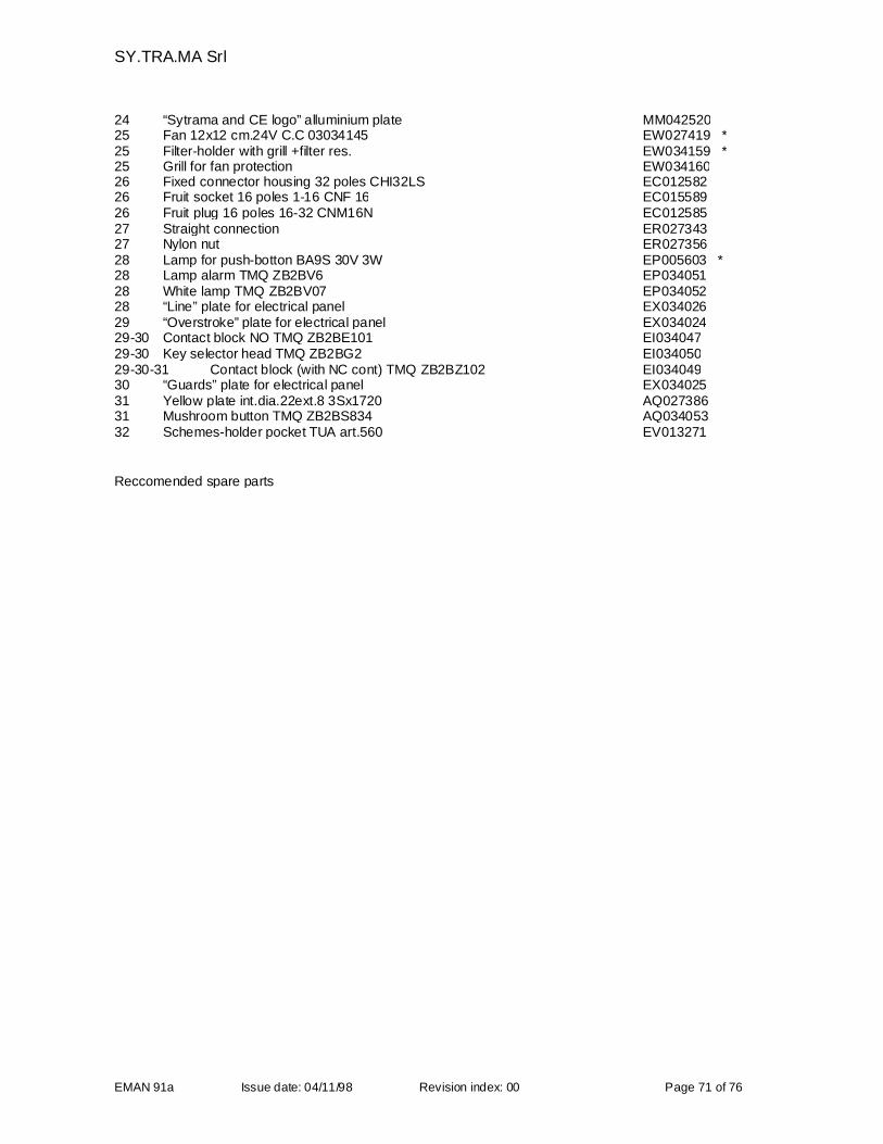
SY.TRA.MA Srl
EMAN 91a Issue date: 04/11/98 Revision index: 00 Page 71 of 76
24 “Sytrama and CE logo” alluminium plate MM04252025 Fan 12x12 cm.24V C.C 03034145 EW027419 *25 Filter-holder with grill +filter res. EW034159 *25 Grill for fan protection EW03416026 Fixed connector housing 32 poles CHI32LS EC01258226 Fruit socket 16 poles 1-16 CNF 16 EC01558926 Fruit plug 16 poles 16-32 CNM16N EC01258527 Straight connection ER02734327 Nylon nut ER02735628 Lamp for push-botton BA9S 30V 3W EP005603 *28 Lamp alarm TMQ ZB2BV6 EP03405128 White lamp TMQ ZB2BV07 EP03405228 “Line” plate for electrical panel EX03402629 “Overstroke” plate for electrical panel EX03402429-30 Contact block NO TMQ ZB2BE101 EI03404729-30 Key selector head TMQ ZB2BG2 EI03405029-30-31 Contact block (with NC cont) TMQ ZB2BZ102 EI03404930 “Guards” plate for electrical panel EX03402531 Yellow plate int.dia.22ext.8 3Sx1720 AQ02738631 Mushroom button TMQ ZB2BS834 AQ03405332 Schemes-holder pocket TUA art.560 EV013271
Reccomended spare parts
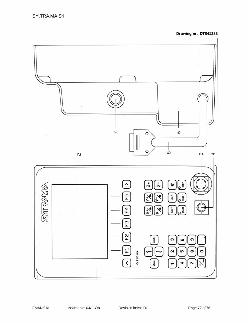
SY.TRA.MA Srl
EMAN 91a Issue date: 04/11/98 Revision index: 00 Page 72 of 76
Drawing nr. DT041288
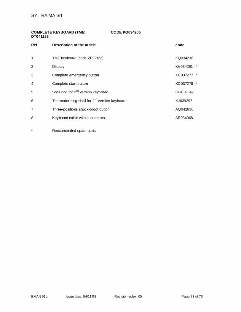
SY.TRA.MA Srl
EMAN 91a Issue date: 04/11/98 Revision index: 00 Page 73 of 76
COMPLETE KEYBOARD (TME) CODE KQ034205DT041288
Ref. Description of the article code
1 TME keyboard (code ZPF-322) KQ034216
2 Display KV034291 *
3 Complete emergency button XC037277 *
4 Complete start button XC037278 *
5 Shell ring for 2nd version keyboard GG039647
6 Thermoforming shell for 2nd
version keyboard XJ039397
7 Three-positions shock-proof button AQ042638
8 Keyboard cable with connectors AE034368
* Reccomended spare parts
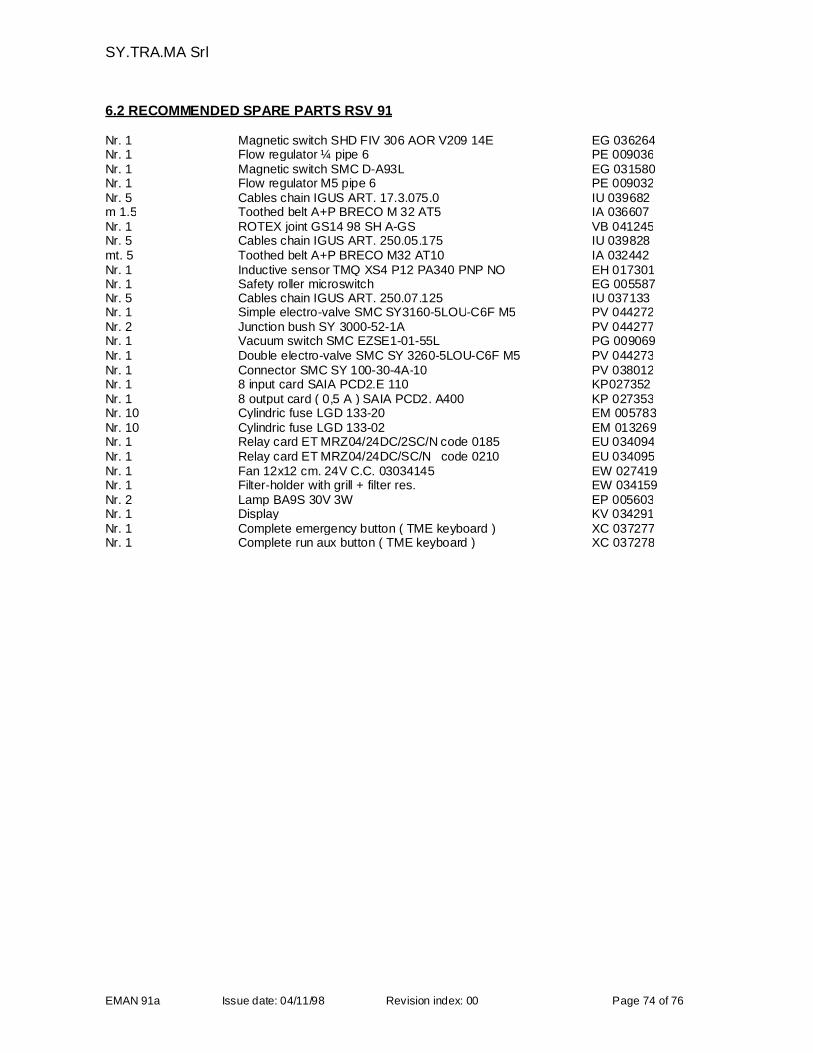
SY.TRA.MA Srl
EMAN 91a Issue date: 04/11/98 Revision index: 00 Page 74 of 76
6.2 RECOMMENDED SPARE PARTS RSV 91
Nr. 1 Magnetic switch SHD FIV 306 AOR V209 14E EG 036264Nr. 1 Flow regulator ¼ pipe 6 PE 009036Nr. 1 Magnetic switch SMC D-A93L EG 031580Nr. 1 Flow regulator M5 pipe 6 PE 009032Nr. 5 Cables chain IGUS ART. 17.3.075.0 IU 039682m 1.5 Toothed belt A+P BRECO M 32 AT5 IA 036607Nr. 1 ROTEX joint GS14 98 SH A-GS VB 041245Nr. 5 Cables chain IGUS ART. 250.05.175 IU 039828mt. 5 Toothed belt A+P BRECO M32 AT10 IA 032442Nr. 1 Inductive sensor TMQ XS4 P12 PA340 PNP NO EH 017301Nr. 1 Safety roller microswitch EG 005587Nr. 5 Cables chain IGUS ART. 250.07.125 IU 037133Nr. 1 Simple electro-valve SMC SY3160-5LOU-C6F M5 PV 044272Nr. 2 Junction bush SY 3000-52-1A PV 044277Nr. 1 Vacuum switch SMC EZSE1-01-55L PG 009069Nr. 1 Double electro-valve SMC SY 3260-5LOU-C6F M5 PV 044273Nr. 1 Connector SMC SY 100-30-4A-10 PV 038012Nr. 1 8 input card SAIA PCD2.E 110 KP027352Nr. 1 8 output card ( 0,5 A ) SAIA PCD2. A400 KP 027353Nr. 10 Cylindric fuse LGD 133-20 EM 005783Nr. 10 Cylindric fuse LGD 133-02 EM 013269Nr. 1 Relay card ET MRZ04/24DC/2SC/N code 0185 EU 034094Nr. 1 Relay card ET MRZ04/24DC/SC/N code 0210 EU 034095Nr. 1 Fan 12x12 cm. 24V C.C. 03034145 EW 027419Nr. 1 Filter-holder with grill + filter res. EW 034159Nr. 2 Lamp BA9S 30V 3W EP 005603Nr. 1 Display KV 034291Nr. 1 Complete emergency button ( TME keyboard ) XC 037277Nr. 1 Complete run aux button ( TME keyboard ) XC 037278
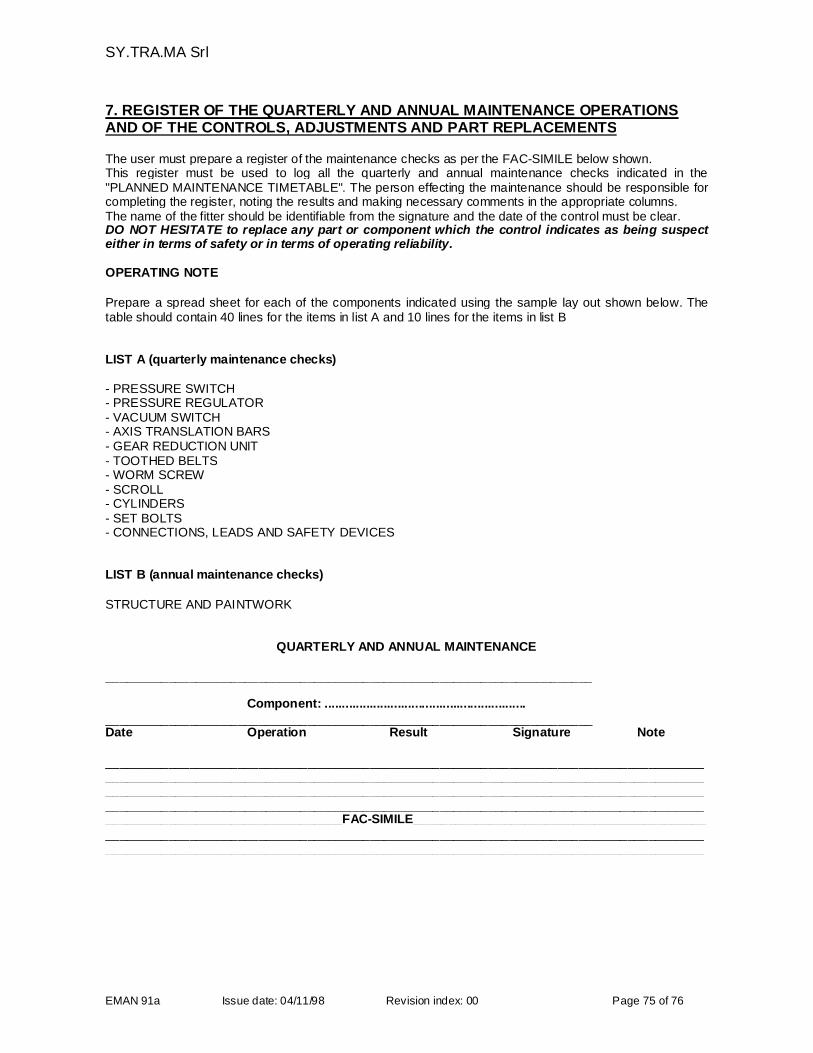
SY.TRA.MA Srl
EMAN 91a Issue date: 04/11/98 Revision index: 00 Page 75 of 76
7. REGISTER OF THE QUARTERLY AND ANNUAL MAINTENANCE OPERATIONSAND OF THE CONTROLS, ADJUSTMENTS AND PART REPLACEMENTS
The user must prepare a register of the maintenance checks as per the FAC-SIMILE below shown.This register must be used to log all the quarterly and annual maintenance checks indicated in the"PLANNED MAINTENANCE TIMETABLE". The person effecting the maintenance should be responsible forcompleting the register, noting the results and making necessary comments in the appropriate columns.The name of the fitter should be identifiable from the signature and the date of the control must be clear.DO NOT HESITATE to replace any part or component which the control indicates as being suspecteither in terms of safety or in terms of operating reliability.
OPERATING NOTE
Prepare a spread sheet for each of the components indicated using the sample lay out shown below. Thetable should contain 40 lines for the items in list A and 10 lines for the items in list B
LIST A (quarterly maintenance checks)
- PRESSURE SWITCH- PRESSURE REGULATOR- VACUUM SWITCH- AXIS TRANSLATION BARS- GEAR REDUCTION UNIT- TOOTHED BELTS- WORM SCREW- SCROLL- CYLINDERS- SET BOLTS- CONNECTIONS, LEADS AND SAFETY DEVICES
LIST B (annual maintenance checks)
STRUCTURE AND PAINTWORK
QUARTERLY AND ANNUAL MAINTENANCE
______________________________________________________________________
Component: ..........................................................
______________________________________________________________________Date Operation Result Signature Note
__________________________________________________________________________________________________________________________________________________________________________________________________________________________________________________________________________________________________________________________________________________________________________________________FAC-SIMILE______________________________________________________________________________________________________________________________________________________________________________________________________________________

SY.TRA.MA Srl
EMAN 91a Issue date: 04/11/98 Revision index: 00 Page 76 of 76
8. ERRATA CORRIGE OR PAGE INTENTIONALLY EMPTY


![Csci 565 Spring 2009. Originally proposed by [Weiser 88]and [Gallagher 91] in software maintenance Useful for Software Debugging Software Maintenance](https://img.pdfslide.us/doc/110x75/56649cca5503460f949922c1/csci-565-spring-2009-originally-proposed-by-weiser-88and-gallagher.jpg)


![na2[W*][E2] d4[W*E2] kl[WE1]](https://img.pdfslide.us/doc/110x75/61b47e93bd377645311b3513/na2we2-d4we2-klwe1.jpg)