Embed Size (px)
Citation preview
1
(1)
Introduction
© Sudhakar Yalamanchili, Georgia Institute of Technology, 2006
(2)
VHDL
• What is VHDL?
V H I S C Very High Speed Integrated Circuit
Hardware
Description
Language IEEE Standard 1076-1993
2
(3)
History of VHDL
• Designed by IBM, Texas Instruments, and Intermetrics as part of the DoD funded VHSIC program
• Standardized by the IEEE in 1987: IEEE 1076-1987• Enhanced version of the language defined in 1993:
IEEE 1076-1993• Additional standardized packages provide definitions
of data types and expressions of timing data– IEEE 1164 (data types)– IEEE 1076.3 (numeric)– IEEE 1076.4 (timing)
(4)
Traditional vs. Hardware Description Languages
• Procedural programming languages provide the howor recipes– for computation– for data manipulation– for execution on a specific hardware model
• Hardware description languages describe a system– Systems can be described from many different points of view
• Behavior: what does it do?• Structure: what is it composed of?• Functional properties: how do I interface to it?• Physical properties: how fast is it?
3
(5)
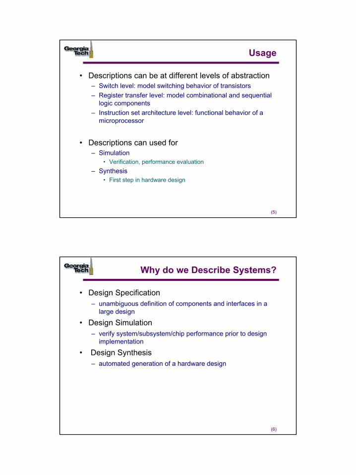
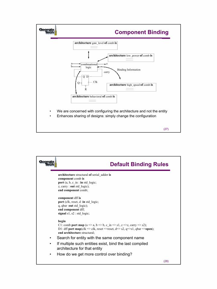
Usage
• Descriptions can be at different levels of abstraction– Switch level: model switching behavior of transistors– Register transfer level: model combinational and sequential
logic components– Instruction set architecture level: functional behavior of a
microprocessor
• Descriptions can used for – Simulation
• Verification, performance evaluation– Synthesis
• First step in hardware design
(6)
Why do we Describe Systems?
• Design Specification – unambiguous definition of components and interfaces in a
large design
• Design Simulation – verify system/subsystem/chip performance prior to design
implementation
• Design Synthesis– automated generation of a hardware design
4
(7)
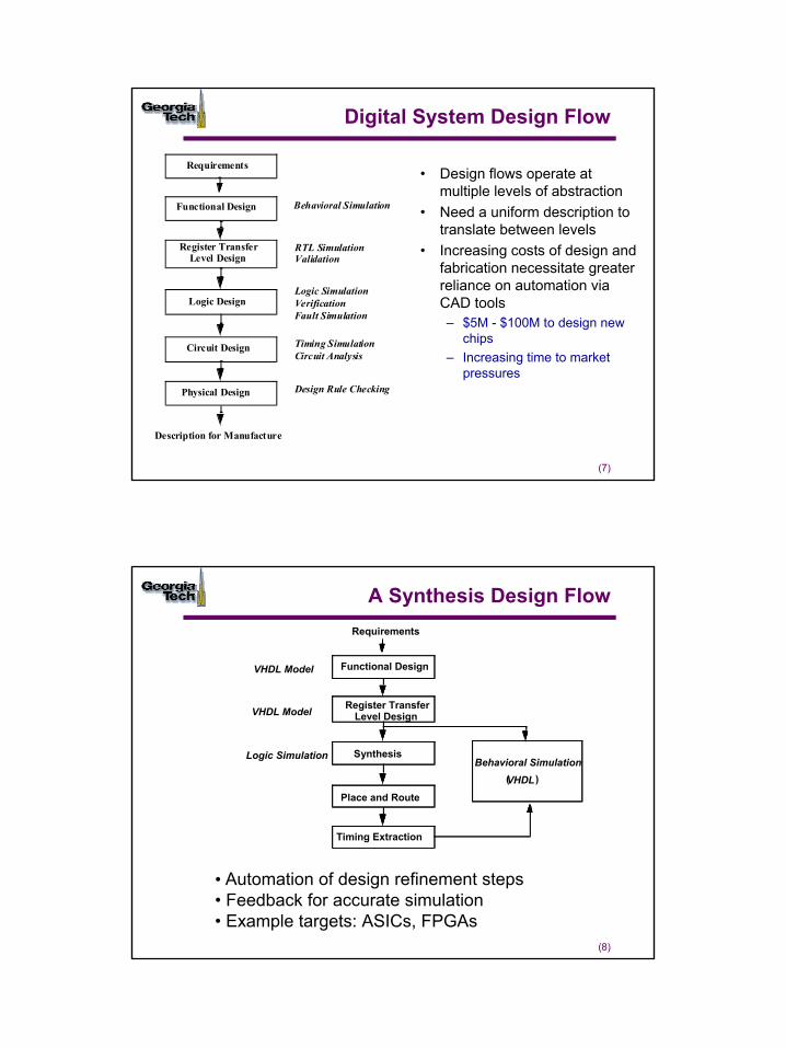
Digital System Design Flow
Requirements
Functional Design
Register TransferLevel Design
Logic Design
Circuit Design
Physical Design
Description for Manufacture
Behavioral Simulation
RTL SimulationValidation
Logic SimulationVerification
Timing SimulationCircuit Analysis
Design Rule Checking
Fault Simulation
• Design flows operate at multiple levels of abstraction
• Need a uniform description to translate between levels
• Increasing costs of design and fabrication necessitate greater reliance on automation via CAD tools– $5M - $100M to design new
chips– Increasing time to market
pressures
(8)
A Synthesis Design FlowRequirements
Functional Design
Register TransferLevel Design
Synthesis
Place and Route
Timing Extraction
VHDL Model
(VHDL)
VHDL Model
Logic SimulationBehavioral Simulation
• Automation of design refinement steps • Feedback for accurate simulation• Example targets: ASICs, FPGAs
5
(9)
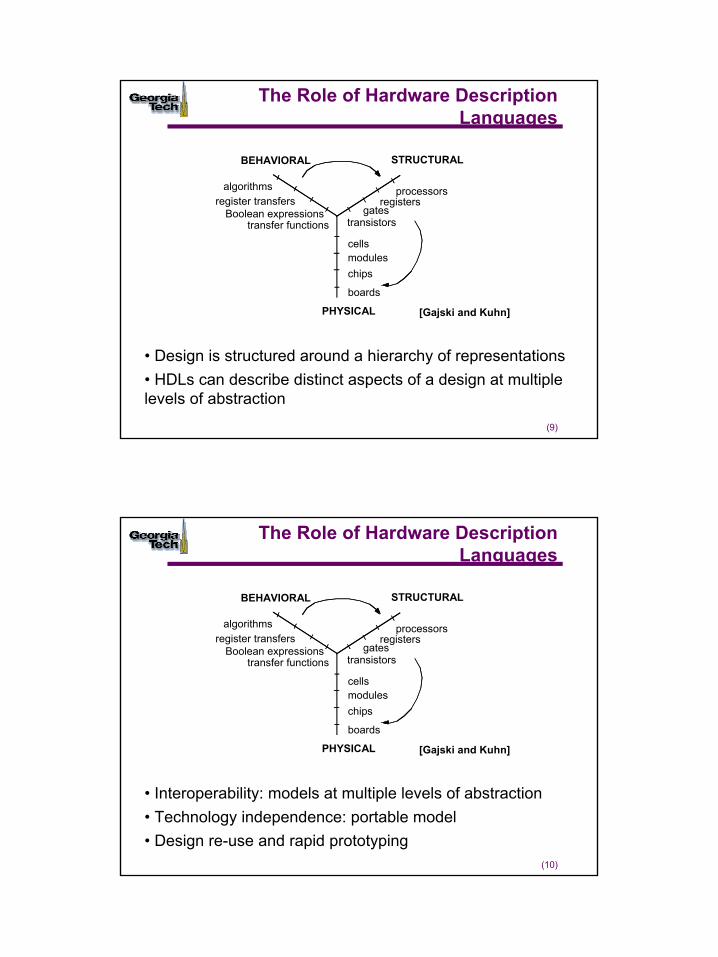
The Role of Hardware Description Languages
cellsmoduleschips
boards
algorithmsregister transfers
Boolean expressionstransfer functions
processorsregisters
gatestransistors
PHYSICAL
BEHAVIORAL STRUCTURAL
[Gajski and Kuhn]
• Design is structured around a hierarchy of representations• HDLs can describe distinct aspects of a design at multiple levels of abstraction
(10)
The Role of Hardware Description Languages
cellsmoduleschips
boards
algorithmsregister transfers
Boolean expressionstransfer functions
processorsregisters
gatestransistors
PHYSICAL
BEHAVIORAL STRUCTURAL
[Gajski and Kuhn]
• Interoperability: models at multiple levels of abstraction• Technology independence: portable model• Design re-use and rapid prototyping
6
(11)
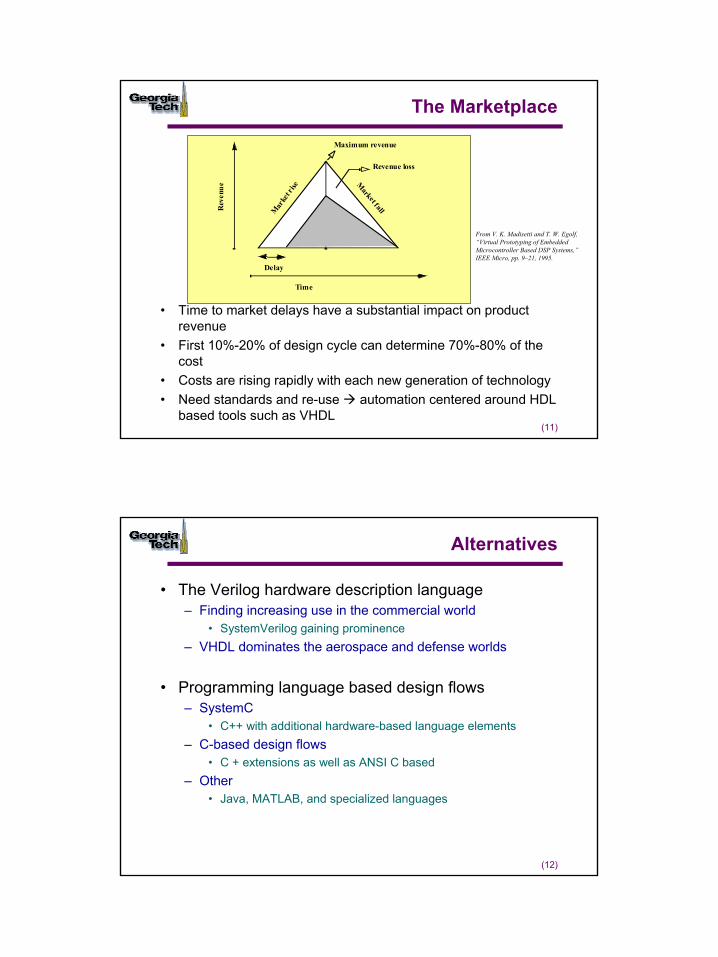
The Marketplace
• Time to market delays have a substantial impact on product revenue
• First 10%-20% of design cycle can determine 70%-80% of the cost
• Costs are rising rapidly with each new generation of technology• Need standards and re-use automation centered around HDL
based tools such as VHDL
Mar
ket r
ise
Market f all
Maximum revenue
Revenue loss
Rev
enue
Time
Delay
From V. K. Madisetti and T. W. Egolf, “Virtual Prototyping of Embedded Microcontroller Based DSP Systems,”IEEE Micro, pp. 9–21, 1995.
(12)
Alternatives
• The Verilog hardware description language– Finding increasing use in the commercial world
• SystemVerilog gaining prominence– VHDL dominates the aerospace and defense worlds
• Programming language based design flows– SystemC
• C++ with additional hardware-based language elements– C-based design flows
• C + extensions as well as ANSI C based– Other
• Java, MATLAB, and specialized languages
7
(13)
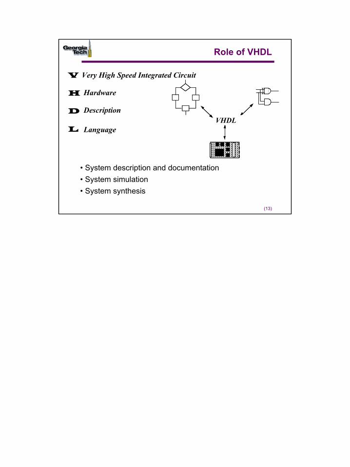
Role of VHDL
VHDL
• System description and documentation• System simulation • System synthesis
V Very High Speed Integrated Circuit
H Hardware
D Description
L Language
1
(1)
Modeling Digital Systems
© Sudhakar Yalamanchili, Georgia Institute of Technology, 2006
(2)
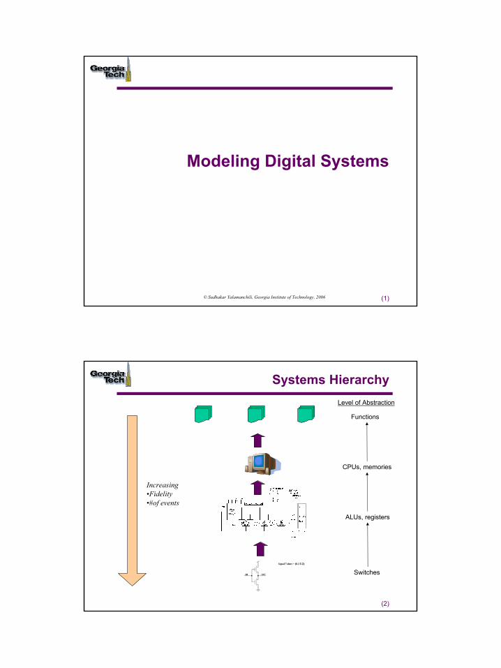
Systems Hierarchy
Functions
CPUs, memories
ALUs, registers
Switches
Increasing•Fidelity•#of events
Level of Abstraction
2
(3)
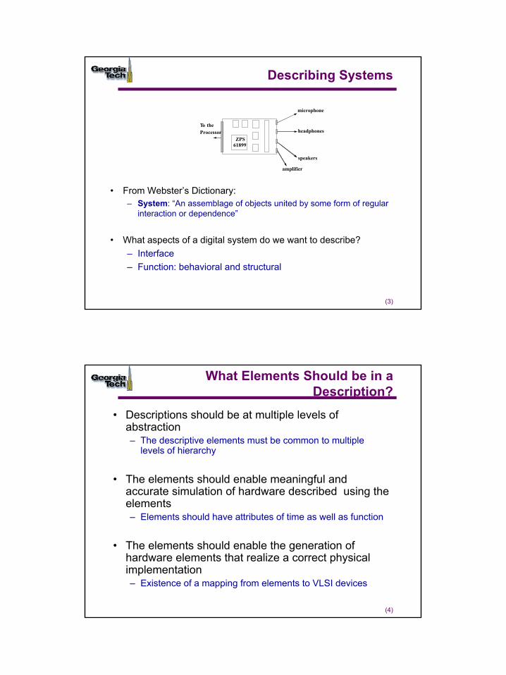
Describing Systems
• From Webster’s Dictionary: – System: “An assemblage of objects united by some form of regular
interaction or dependence”
• What aspects of a digital system do we want to describe?– Interface– Function: behavioral and structural
To the Processor
microphone
headphones
speakers
amplifier
ZPS61899
(4)
What Elements Should be in a Description?
• Descriptions should be at multiple levels of abstraction– The descriptive elements must be common to multiple
levels of hierarchy
• The elements should enable meaningful and accurate simulation of hardware described using the elements– Elements should have attributes of time as well as function
• The elements should enable the generation of hardware elements that realize a correct physical implementation – Existence of a mapping from elements to VLSI devices

3
(5)
What Elements Should be in a Description?
• VHDL was conceived for the description of digital systems– From switches to networked systems
• Keep in mind the pragmatic issues of design re-use and portability of descriptions– Portability across technology generations– Portability across a range of cost/performance points
• Attributes of digital systems serve as the starting point– Language features designed to capture the key attributes
(6)
Attributes of Digital Systems
• Digital systems are about signals and their values• Events, propagation delays, concurrency
– Signal value changes at specific points in time• Time ordered sequence of events produces a waveform
10 15 20 25 30 35 40
a
b
sum
carry
5Time (ns)
Eventab
sum
carry
4
(7)
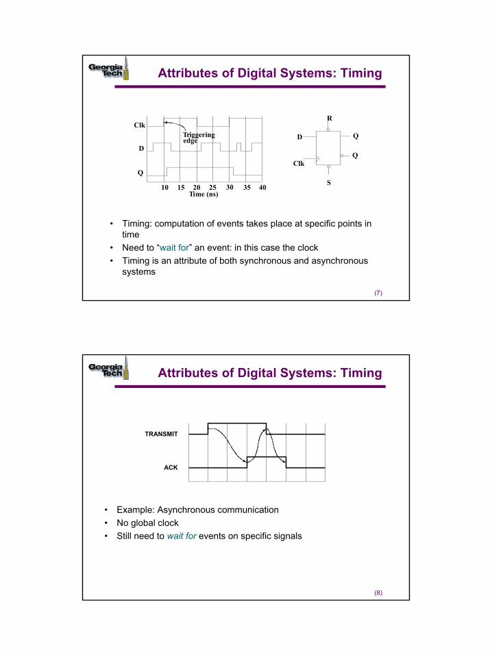
Attributes of Digital Systems: Timing
• Timing: computation of events takes place at specific points in time
• Need to “wait for” an event: in this case the clock• Timing is an attribute of both synchronous and asynchronous
systems
D
Clk
S
Q
R
10 15 20 25 30 35 40
Clk
D
Q
Time (ns)
Triggeringedge
Q
(8)
Attributes of Digital Systems: Timing
• Example: Asynchronous communication• No global clock• Still need to wait for events on specific signals
TRANSMIT
ACK
5
(9)
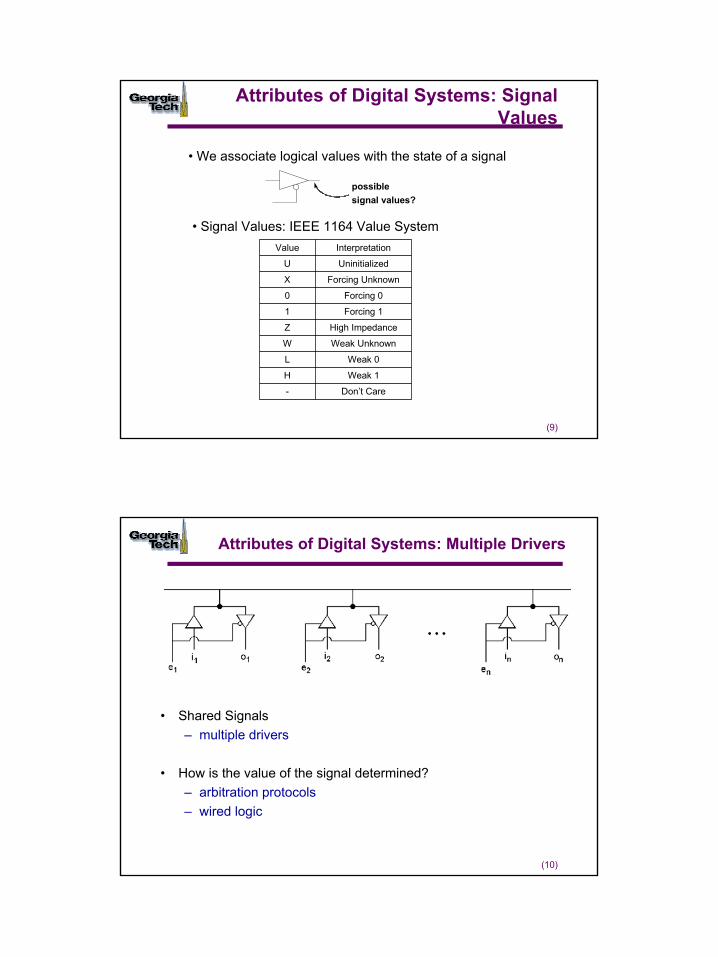
Attributes of Digital Systems: Signal Values
possiblesignal values?
• We associate logical values with the state of a signal
• Signal Values: IEEE 1164 Value System
Don’t Care-
Weak 1H
Weak 0L
Weak UnknownW
High ImpedanceZ
Forcing 11
Forcing 00
Forcing UnknownX
UninitializedU
InterpretationValue
(10)
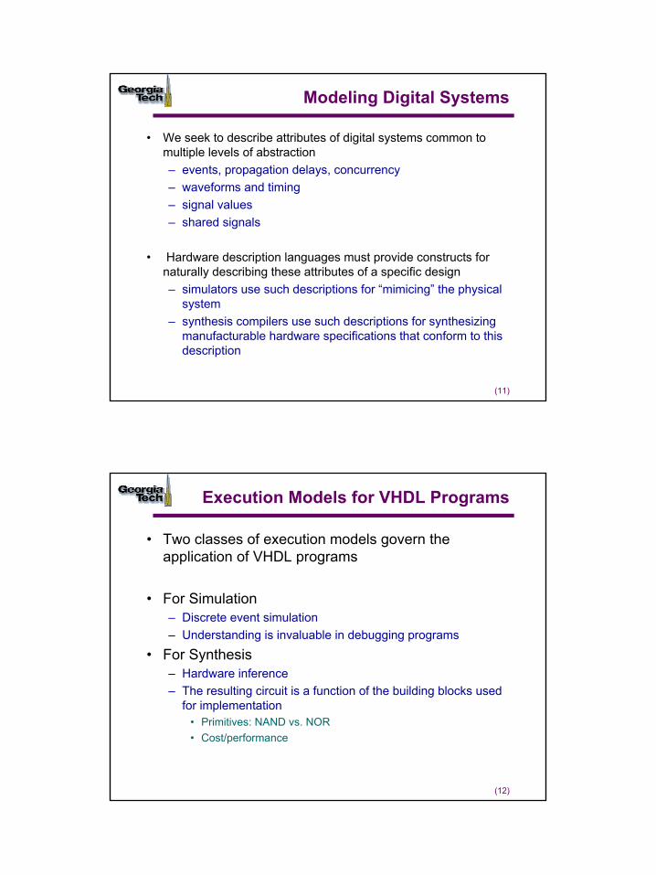
Attributes of Digital Systems: Multiple Drivers
• Shared Signals– multiple drivers
• How is the value of the signal determined?– arbitration protocols– wired logic
6
(11)
Modeling Digital Systems
• We seek to describe attributes of digital systems common to multiple levels of abstraction– events, propagation delays, concurrency– waveforms and timing – signal values– shared signals
• Hardware description languages must provide constructs for naturally describing these attributes of a specific design– simulators use such descriptions for “mimicing” the physical
system– synthesis compilers use such descriptions for synthesizing
manufacturable hardware specifications that conform to this description
(12)
Execution Models for VHDL Programs
• Two classes of execution models govern the application of VHDL programs
• For Simulation– Discrete event simulation– Understanding is invaluable in debugging programs
• For Synthesis– Hardware inference– The resulting circuit is a function of the building blocks used
for implementation• Primitives: NAND vs. NOR• Cost/performance
7
(13)
Simulation vs. Synthesis
• Simulation and synthesis are complementary processes
entity my_ckt is port(x, y :in bit; z : out bit)end entity my_ckt;architecture behavioral ofmy_ckt is begin -- some code here--end architecture behavioral;
entity my_ckt is port(x, y :in bit; z : out bit)end entity my_ckt;architecture behavioral ofmy_ckt is begin -- some code here--end architecture behavioral;
synthesis
simulation
(14)
Simulation of Digital Systems
• Digital systems are modeled as the generation of events – value transitions – on signals
• Discrete event simulations manage the generation and ordering ofevents
– Correct sequencing of event processing– Correct sequencing of computations caused by events
@5 ns
@10 ns
@15 ns
@5 ns
v1 v2@5ns
v3 v4@10ns
v5 v6@15ns
Head
0
8
(15)
Discrete Event Simulation: Example
1 0a@5ns
U 1carry@5ns
U 0sum@5ns
0 1sum@10ns
1 0carry@10ns
0 1a@10ns
1 0b@10ns
1 0a@15ns
5ns
10ns
10ns
Initial state: a = b = 1, sum = carry = UEvent List HeadSimulation Time
0ns U 1carry@5ns
U 0sum@5ns New event generated
from inputUpdate time
Update signal values, execute, generate new events, update time
Update signal values, execute, generate new events
10 15 20 25 30 35 40
a
b
sum
carry
5
Event
ba sum
carry
(16)
Discrete Event Simulation
• Management of simulation time: ordering of events
• Two step model of the progression of time– Evaluate all affected components at the current time: events on input
signals– Schedule future events and move to the next time step: the next time
at which events take place
9
(17)
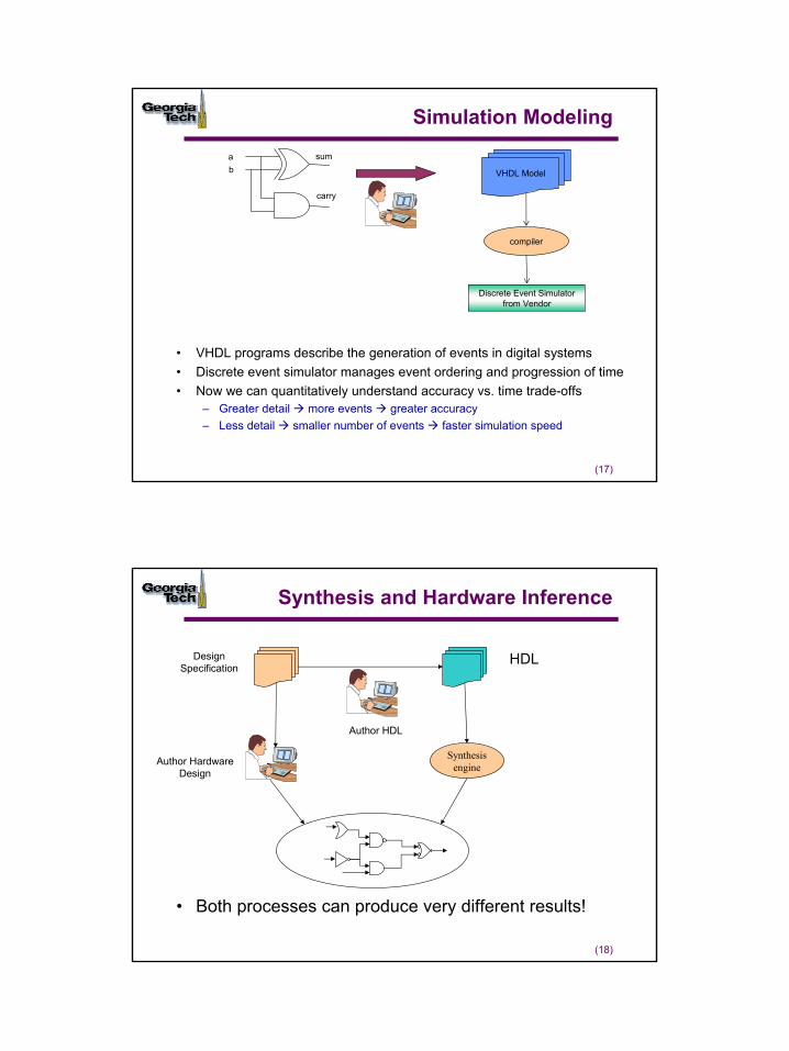
Simulation Modeling
• VHDL programs describe the generation of events in digital systems• Discrete event simulator manages event ordering and progression of time• Now we can quantitatively understand accuracy vs. time trade-offs
– Greater detail more events greater accuracy– Less detail smaller number of events faster simulation speed
ba sum
carry
VHDL Model
compiler
Discrete Event Simulator from Vendor
(18)
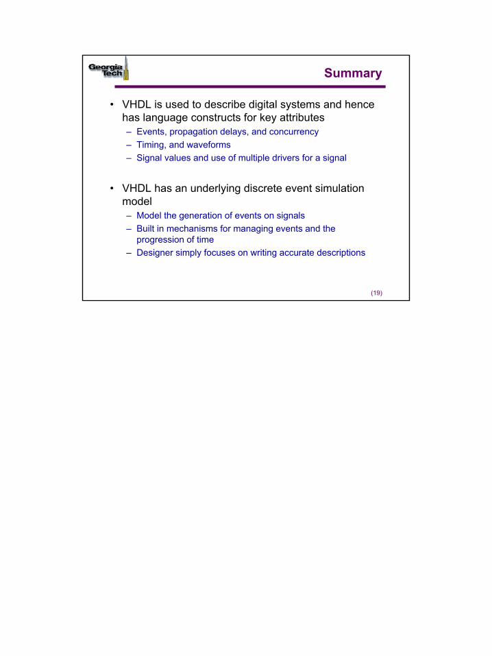
Synthesis and Hardware Inference
• Both processes can produce very different results!
Synthesis engine
HDLDesign Specification
Author HDL
Author Hardware Design
10
(19)
Summary
• VHDL is used to describe digital systems and hence has language constructs for key attributes– Events, propagation delays, and concurrency– Timing, and waveforms– Signal values and use of multiple drivers for a signal
• VHDL has an underlying discrete event simulation model– Model the generation of events on signals– Built in mechanisms for managing events and the
progression of time– Designer simply focuses on writing accurate descriptions
1
(1)
Basic Language Concepts
© Sudhakar Yalamanchili, Georgia Institute of Technology, 2006
(2)
Describing Design Entities
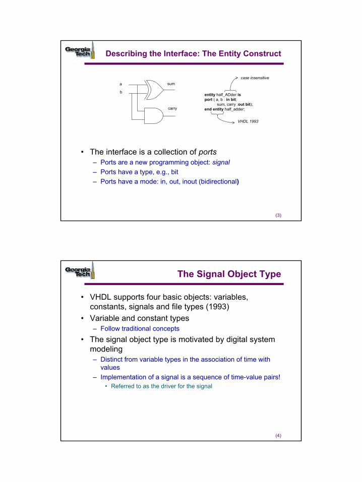
• Primary programming abstraction is a design entity– Register, logic block, chip, board, or system
• What aspects of a digital system do we want to describe?– Interface: how do we connect to it– Function: what does it do?
• VHDL 1993 vs. VHDL 1987
b
a sum
carry
2
(3)
Describing the Interface: The Entity Construct
• The interface is a collection of ports– Ports are a new programming object: signal– Ports have a type, e.g., bit– Ports have a mode: in, out, inout (bidirectional)
entity half_ADder isport ( a, b : in bit;
sum, carry :out bit);end entity half_adder;
case insensitive
VHDL 1993
b
a sum
carry
(4)
The Signal Object Type
• VHDL supports four basic objects: variables, constants, signals and file types (1993)
• Variable and constant types– Follow traditional concepts
• The signal object type is motivated by digital system modeling– Distinct from variable types in the association of time with
values– Implementation of a signal is a sequence of time-value pairs!
• Referred to as the driver for the signal
3
(5)
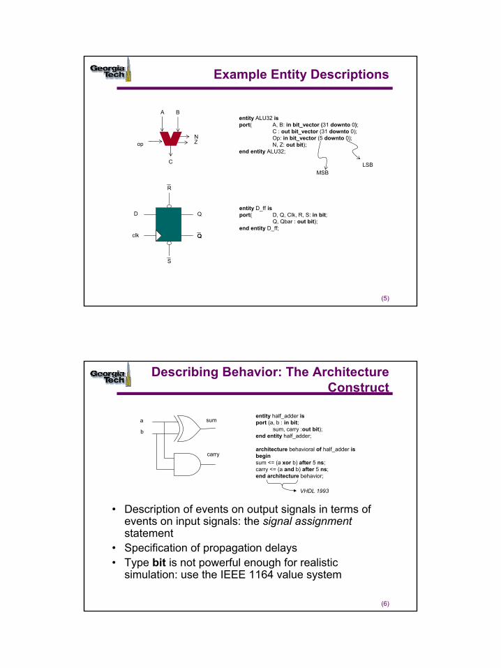
Example Entity Descriptions
Q
D
clk
R
S
opNZ
A B
C
entity ALU32 isport( A, B: in bit_vector (31 downto 0);
C : out bit_vector (31 downto 0);Op: in bit_vector (5 downto 0);N, Z: out bit);
end entity ALU32;
entity D_ff isport( D, Q, Clk, R, S: in bit;
Q, Qbar : out bit);end entity D_ff;
MSBLSB
(6)
Describing Behavior: The Architecture Construct
• Description of events on output signals in terms of events on input signals: the signal assignment statement
• Specification of propagation delays• Type bit is not powerful enough for realistic
simulation: use the IEEE 1164 value system
b
a sum
carry
entity half_adder isport (a, b : in bit;
sum, carry :out bit);end entity half_adder;
architecture behavioral of half_adder isbeginsum <= (a xor b) after 5 ns;carry <= (a and b) after 5 ns;end architecture behavior;
VHDL 1993
4
(7)
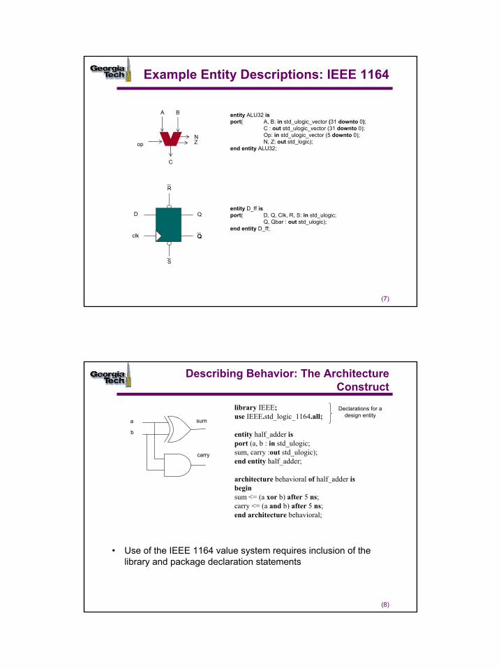
Example Entity Descriptions: IEEE 1164
Q
D
clk
R
S
opNZ
A B
C
entity D_ff isport( D, Q, Clk, R, S: in std_ulogic;
Q, Qbar : out std_ulogic);end entity D_ff;
entity ALU32 isport( A, B: in std_ulogic_vector (31 downto 0);
C : out std_ulogic_vector (31 downto 0);Op: in std_ulogic_vector (5 downto 0);N, Z: out std_logic);
end entity ALU32;
(8)
Describing Behavior: The Architecture Construct
library IEEE;use IEEE.std_logic_1164.all;
entity half_adder isport (a, b : in std_ulogic;sum, carry :out std_ulogic);end entity half_adder;
architecture behavioral of half_adder isbeginsum <= (a xor b) after 5 ns;carry <= (a and b) after 5 ns;end architecture behavioral;
• Use of the IEEE 1164 value system requires inclusion of the library and package declaration statements
b
a sum
carry
Declarations for a design entity
5
(9)
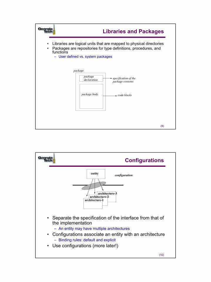
Libraries and Packages
• Libraries are logical units that are mapped to physical directories• Packages are repositories for type definitions, procedures, and
functions– User defined vs. system packages
package
package
package body
specification of the
code blocks
declaration package contents
(10)
Configurations
architecture-3architecture-2
architecture-1
entity configuration
• Separate the specification of the interface from that of the implementation – An entity may have multiple architectures
• Configurations associate an entity with an architecture– Binding rules: default and explicit
• Use configurations (more later!)
6
(11)
Design Units
• Primary design units– Entity– Configuration – Package Declaration– These are not dependent on other design units
• Secondary design units – Package body– Architecture
• Design units are created in design files
• Now you know the layout of a VHDL program!
(12)
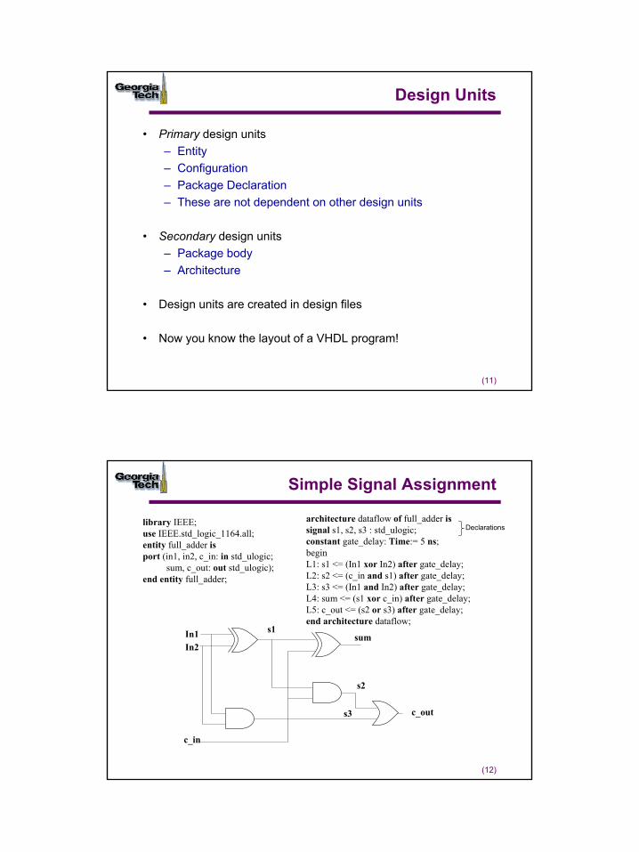
Simple Signal Assignment
In1In2
c_in
c_out
sums1
s3
s2
library IEEE;use IEEE.std_logic_1164.all;entity full_adder isport (in1, in2, c_in: in std_ulogic;
sum, c_out: out std_ulogic);end entity full_adder;
architecture dataflow of full_adder issignal s1, s2, s3 : std_ulogic;constant gate_delay: Time:= 5 ns;beginL1: s1 <= (In1 xor In2) after gate_delay;L2: s2 <= (c_in and s1) after gate_delay;L3: s3 <= (In1 and In2) after gate_delay;L4: sum <= (s1 xor c_in) after gate_delay;L5: c_out <= (s2 or s3) after gate_delay;end architecture dataflow;
Declarations
7
(13)
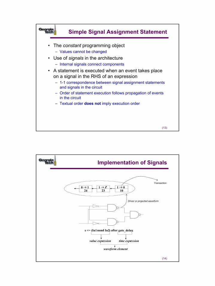
Simple Signal Assignment Statement
• The constant programming object– Values cannot be changed
• Use of signals in the architecture– Internal signals connect components
• A statement is executed when an event takes place on a signal in the RHS of an expression– 1-1 correspondence between signal assignment statements
and signals in the circuit– Order of statement execution follows propagation of events
in the circuit – Textual order does not imply execution order
(14)
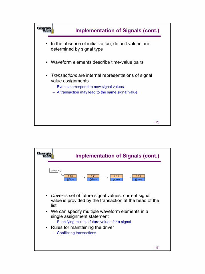
Implementation of Signals
101 0→
231 Z→
240 1→
s <= (In1nand In2) after gate_delay;
value expression time expression
waveform element
Driver or projected waveform
Transaction
8
(15)
Implementation of Signals (cont.)
• In the absence of initialization, default values are determined by signal type
• Waveform elements describe time-value pairs
• Transactions are internal representations of signal value assignments– Events correspond to new signal values– A transaction may lead to the same signal value
(16)
Implementation of Signals (cont.)
• Driver is set of future signal values: current signal value is provided by the transaction at the head of the list
• We can specify multiple waveform elements in a single assignment statement– Specifying multiple future values for a signal
• Rules for maintaining the driver– Conflicting transactions
0 1@24ns
1 0@30ns
0 1@20ns
1 0@18ns
driver
9
(17)
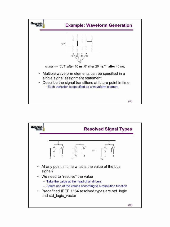
Example: Waveform Generation
• Multiple waveform elements can be specified in a single signal assignment statement
• Describe the signal transitions at future point in time– Each transition is specified as a waveform element
10 4020 30
signal <= ‘0’,‘1’ after 10 ns,‘0’ after 20 ns,‘1’ after 40 ns;
signal
(18)
Resolved Signal Types
• At any point in time what is the value of the bus signal?
• We need to “resolve” the value– Take the value at the head of all drivers– Select one of the values according to a resolution function
• Predefined IEEE 1164 resolved types are std_logic and std_logic_vector
10
(19)
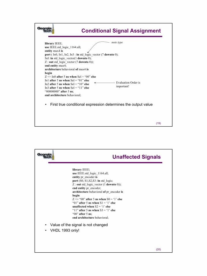
Conditional Signal Assignment
• First true conditional expression determines the output value
library IEEE;use IEEE.std_logic_1164.all;entity mux4 isport ( In0, In1, In2, In3 : in std_logic_vector (7 downto 0);Sel: in std_logic_vector(1 downto 0);Z : out std_logic_vector (7 downto 0));end entity mux4;architecture behavioral of mux4 isbeginZ <= In0 after 5 ns when Sel = “00” elseIn1 after 5 ns when Sel = “01” elseIn2 after 5 ns when Sel = “10” elseIn3 after 5 ns when Sel = “11” else“00000000” after 5 ns;end architecture behavioral;
note type
Evaluation Order is important!
(20)
Unaffected Signals
• Value of the signal is not changed• VHDL 1993 only!
library IEEE;use IEEE.std_logic_1164.all;entity pr_encoder isport (S0, S1,S2,S3: in std_logic;Z : out std_logic_vector (1 downto 0));end entity pr_encoder;architecture behavioral of pr_encoder isbeginZ <= “00” after 5 ns when S0 = ‘1’ else“01” after 5 ns when S1 = ‘1’ elseunaffected when S2 = ‘1’ else“11” after 5 ns when S3 = ‘1’ else“00” after 5 ns;end architecture behavioral;
11
(21)
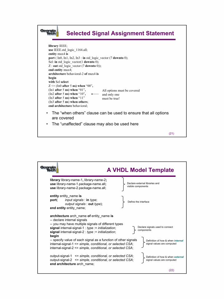
Selected Signal Assignment Statement
• The “when others” clause can be used to ensure that all options are covered
• The “unaffected” clause may also be used here
library IEEE;use IEEE.std_logic_1164.all;entity mux4 isport ( In0, In1, In2, In3 : in std_logic_vector (7 downto 0);Sel: in std_logic_vector(1 downto 0);Z : out std_logic_vector (7 downto 0));end entity mux4;architecture behavioral-2 of mux4 isbeginwith Sel selectZ <= (In0 after 5 ns) when “00”,(In1 after 5 ns) when “01”,(In2 after 5 ns) when “10”,(In3 after 5 ns) when “11”(In3 after 5 ns) when others;end architecture behavioral;
All options must be coveredand only one must be true!
(22)
A VHDL Model Templatelibrary library-name-1, library-name-2;use library-name-1.package-name.all;use library-name-2.package-name.all;
entity entity_name isport( input signals : in type;
output signals : out type);end entity entity_name;
architecture arch_name of entity_name is-- declare internal signals-- you may have multiple signals of different typessignal internal-signal-1 : type := initialization;signal internal-signal-2 : type := initialization;begin-- specify value of each signal as a function of other signals internal-signal-1 <= simple, conditional, or selected CSA;internal-signal-2 <= simple, conditional, or selected CSA;
output-signal-1 <= simple, conditional, or selected CSA;output-signal-2 <= simple, conditional, or selected CSA; end architecture arch_name;
Declare external libraries and visible components
Define the interface
Declare signals used to connect components
Definition of how & when internalsignal values are computed
Definition of how & when externalsignal values are computed
12
(23)
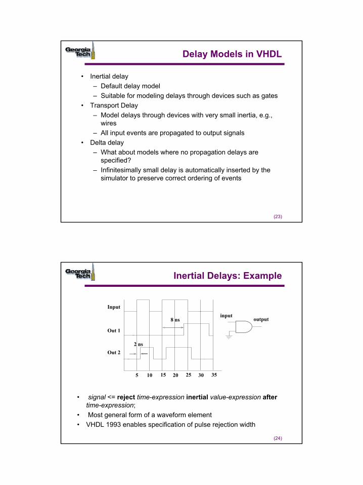
Delay Models in VHDL
• Inertial delay– Default delay model– Suitable for modeling delays through devices such as gates
• Transport Delay– Model delays through devices with very small inertia, e.g.,
wires– All input events are propagated to output signals
• Delta delay– What about models where no propagation delays are
specified?– Infinitesimally small delay is automatically inserted by the
simulator to preserve correct ordering of events
(24)
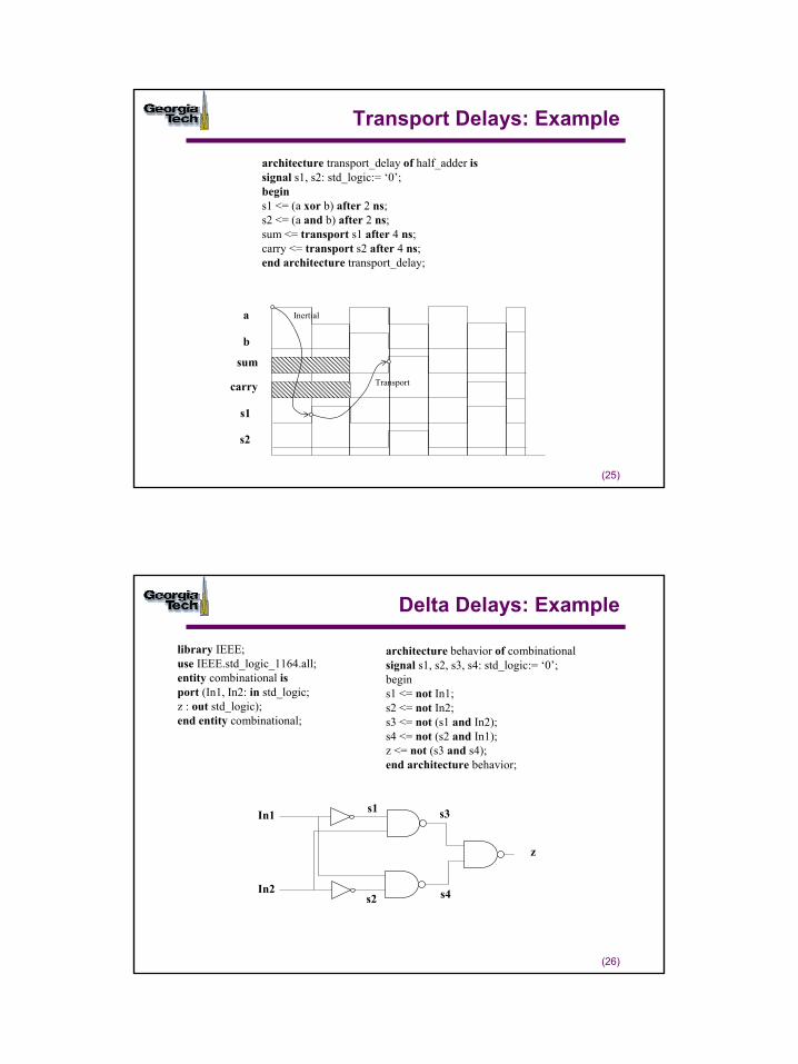
Inertial Delays: Example
• signal <= reject time-expression inertial value-expression aftertime-expression;
• Most general form of a waveform element• VHDL 1993 enables specification of pulse rejection width
Input
Out 1
Out 2
5 10 15 20 25 30 35
inputoutput8 ns
2 ns
13
(25)
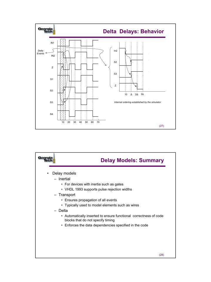
Transport Delays: Example
a
b
sum
carry
s1
s2
Transport
architecture transport_delay of half_adder issignal s1, s2: std_logic:= ‘0’;begins1 <= (a xor b) after 2 ns;s2 <= (a and b) after 2 ns;sum <= transport s1 after 4 ns;carry <= transport s2 after 4 ns;end architecture transport_delay;
Inertial
(26)
Delta Delays: Example
In1
In2
z
s1
s2
s3
s4
library IEEE;use IEEE.std_logic_1164.all;entity combinational isport (In1, In2: in std_logic;z : out std_logic);end entity combinational;
architecture behavior of combinationalsignal s1, s2, s3, s4: std_logic:= ‘0’;begins1 <= not In1;s2 <= not In2;s3 <= not (s1 and In2);s4 <= not (s2 and In1);z <= not (s3 and s4);end architecture behavior;
14
(27)
Delta Delays: Behavior
IN1
IN2
Z
S1
S2
S3
S4
10 20 30 40 50 60 70
10 ∆ 2∆ 3∆
In2
S2
S3
Z
Delta Events
Internal ordering established by the simulator
(28)
Delay Models: Summary
• Delay models– Inertial
• For devices with inertia such as gates• VHDL 1993 supports pulse rejection widths
– Transport• Ensures propagation of all events• Typically used to model elements such as wires
– Delta • Automatically inserted to ensure functional correctness of code
blocks that do not specify timing• Enforces the data dependencies specified in the code
15
(29)
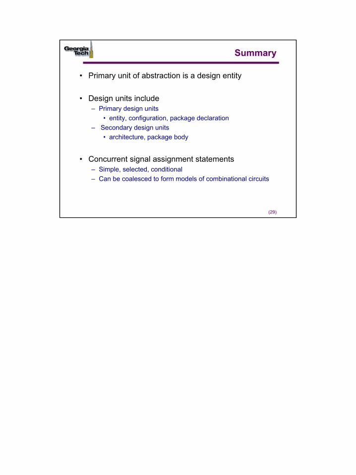
Summary
• Primary unit of abstraction is a design entity
• Design units include– Primary design units
• entity, configuration, package declaration– Secondary design units
• architecture, package body
• Concurrent signal assignment statements– Simple, selected, conditional– Can be coalesced to form models of combinational circuits
1
(1)
Modeling Complex Behavior
© Sudhakar Yalamanchili, Georgia Institute of Technology, 2006
(2)
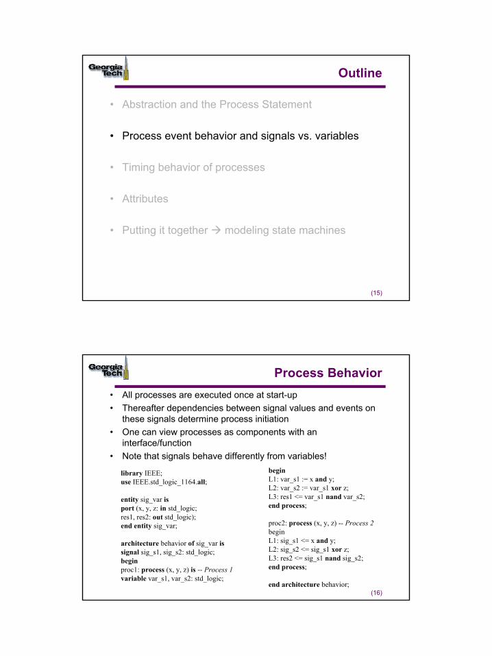
Outline
• Abstraction and the Process Statement– Concurrent processes and CSAs
• Process event behavior and signals vs. variables
• Timing behavior of processes
• Attributes
• Putting it together modeling state machines
2
(3)
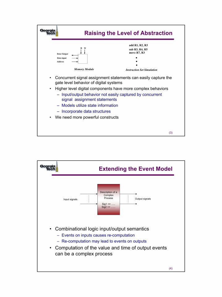
Raising the Level of Abstraction
R W
Data input
Data Output
Address
Memory Module
add R1, R2, R3sub R3, R4, R5move R7, R3...
Instruction Set Simulation
• Concurrent signal assignment statements can easily capture the gate level behavior of digital systems
• Higher level digital components have more complex behaviors – Input/output behavior not easily captured by concurrent
signal assignment statements– Models utilize state information – Incorporate data structures
• We need more powerful constructs
(4)
Extending the Event Model
• Combinational logic input/output semantics– Events on inputs causes re-computation– Re-computation may lead to events on outputs
• Computation of the value and time of output events can be a complex process
Description of a Complex Process
Sig1 <= …..Sig2 <= …...
Input signals Output signals
3
(5)
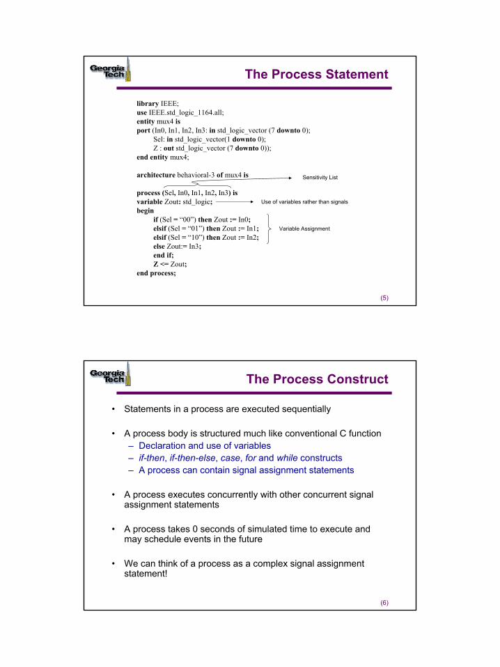
library IEEE;use IEEE.std_logic_1164.all;entity mux4 isport (In0, In1, In2, In3: in std_logic_vector (7 downto 0);
Sel: in std_logic_vector(1 downto 0);Z : out std_logic_vector (7 downto 0));
end entity mux4;
architecture behavioral-3 of mux4 is
process (Sel, In0, In1, In2, In3) isvariable Zout: std_logic;begin
if (Sel = “00”) then Zout := In0;elsif (Sel = “01”) then Zout := In1;elsif (Sel = “10”) then Zout := In2;else Zout:= In3;end if;Z <= Zout;
end process;
The Process Statement
Use of variables rather than signals
Variable Assignment
Sensitivity List
(6)
The Process Construct
• Statements in a process are executed sequentially
• A process body is structured much like conventional C function– Declaration and use of variables– if-then, if-then-else, case, for and while constructs– A process can contain signal assignment statements
• A process executes concurrently with other concurrent signal assignment statements
• A process takes 0 seconds of simulated time to execute and may schedule events in the future
• We can think of a process as a complex signal assignment statement!
4
(7)
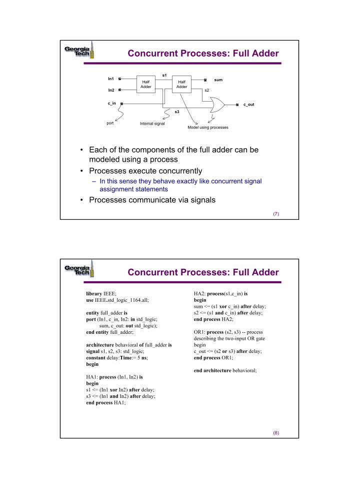
Concurrent Processes: Full Adder
• Each of the components of the full adder can be modeled using a process
• Processes execute concurrently– In this sense they behave exactly like concurrent signal
assignment statements
• Processes communicate via signals
Half Adder
Half Adder
In1
In2
c_in
s1
s3
s2
sum
c_out
portModel using processes
Internal signal
(8)
Concurrent Processes: Full Adder
library IEEE;use IEEE.std_logic_1164.all;
entity full_adder isport (In1, c_in, In2: in std_logic;
sum, c_out: out std_logic);end entity full_adder;
architecture behavioral of full_adder issignal s1, s2, s3: std_logic;constant delay:Time:= 5 ns;begin
HA1: process (In1, In2) isbegins1 <= (In1 xor In2) after delay;s3 <= (In1 and In2) after delay;end process HA1;
HA2: process(s1,c_in) isbeginsum <= (s1 xor c_in) after delay;s2 <= (s1 and c_in) after delay;end process HA2;
OR1: process (s2, s3) -- processdescribing the two-input OR gatebeginc_out <= (s2 or s3) after delay;end process OR1;
end architecture behavioral;
5
(9)
Concurrent Processes: Half Adder
library IEEE;use IEEE.std_logic_1164.all;
entity half_adder isport (a, b : in std_logic;sum, carry : out std_logic);end entity half_adder;
architecture behavior of half_adder isbegin
sum_proc: process(a,b) isbeginif (a = b) thensum <= ‘0’ after 5 ns;elsesum <= (a or b) after 5 ns;end if;end process;
carry_proc: process (a,b) isbegincase a iswhen ‘0’ =>carry <= a after 5 ns;when ‘1’ =>carry <= b after 5 ns;when others =>carry <= ‘X’ after 5 ns;end case;end process carry_proc;
end architecture behavior;
(10)
Processes + CSAs
library IEEE;use IEEE.std_logic_1164.all;use IEEE.std_logic_arith.all;
entity memory isport (address, write_data: in std_logic_vector (7 downto 0);MemWrite, MemRead, clk, reset: in std_logic;read_data: out std_logic_vector (7 downto 0));end entity memory;
architecture behavioral of memory issignal dmem0,dmem1,dmem2,dmem3: std_logic_vector (7 downto 0);beginmem_proc: process (clk) is-- process bodyend process mem_proc;-- read operation CSAend architecture behavioral;
MemRead MemWrite
address
write_data
read_data
clk reset
6
(11)
Process + CSAs: The Write Process
mem_proc: process (clk) isbeginif (rising_edge(clk)) then -- wait until next clock edgeif reset = ‘1’ then -- initialize values on resetdmem0 <= x”00”; -- memory locations are initialized todmem1 <= x”11”;-- some random valuesdmem2 <= x”22”;dmem3 <= x”33”;elsif MemWrite = ‘1’ then -- if not reset then check for memory writecase address (1 downto 0) iswhen “00” => dmem0 <= write_data;when “01” => dmem1 <= write_data;when “10” => dmem2 <= write_data;when “11” => dmem3 <= write_data;when others => dmem0 <= x“ff”;end case;end if;end if;end process mem_proc;
(12)
Process + CSAs: The Read Statement
• A process can be viewed as single concurrent signal assignment statement– The external behavior is the same as a CSA– Processes describe more complex event generation
behavior
• Processes execute concurrently in simulated time with other CSAs
- memory read is implemented with a conditional signal assignmentread_data <= dmem0 when address (1 downto 0) = “00” and MemRead = ‘1’ elsedmem1 when address (1 downto 0) = “01” and MemRead = ‘1’ elsedmem2 when address (1 downto 0) = “10” and MemRead = ‘1’ elsedmem3 when address (1 downto 0) = “11” and MemRead = ‘1’ elsex”00”;
7
(13)
Iteration
architecture behavioral of mult32 isconstant module_delay: Time:= 10 ns; beginmult_process: process(multiplicand,multiplier) isvariable product_register : std_logic_vector (63 downto 0) := X”0000000000000000”;variable multiplicand_register : std_logic_vector (31 downto 0):= X”00000000”;
beginmultiplicand_register := multiplicand;product_register(63 downto 0) := X”00000000” & multiplier;for index in 1 to 32 loopif product_register(0) = ‘1’ thenproduct_register(63 downto 32) := product_register (63 downto 32) +
multiplicand_register(31 downto 0);end if;
-- perform a right shift with zero fill product_register (63 downto 0) := ‘0’ & product_register (63 downto 1);end loop;-- write result to output portproduct <= product_register after module_delay;
end process mult_process;
Concatenation operator
Example: A Simple Multiplier
(14)
Iteration
• for loop index– Implicit declaration via “use”
• Scope is local to the loop– Cannot be used elsewhere in model
• while loop– Boolean expression for termination
while j < 32 loop......j := j+1;end loop;
8
(15)
Outline
• Abstraction and the Process Statement
• Process event behavior and signals vs. variables
• Timing behavior of processes
• Attributes
• Putting it together modeling state machines
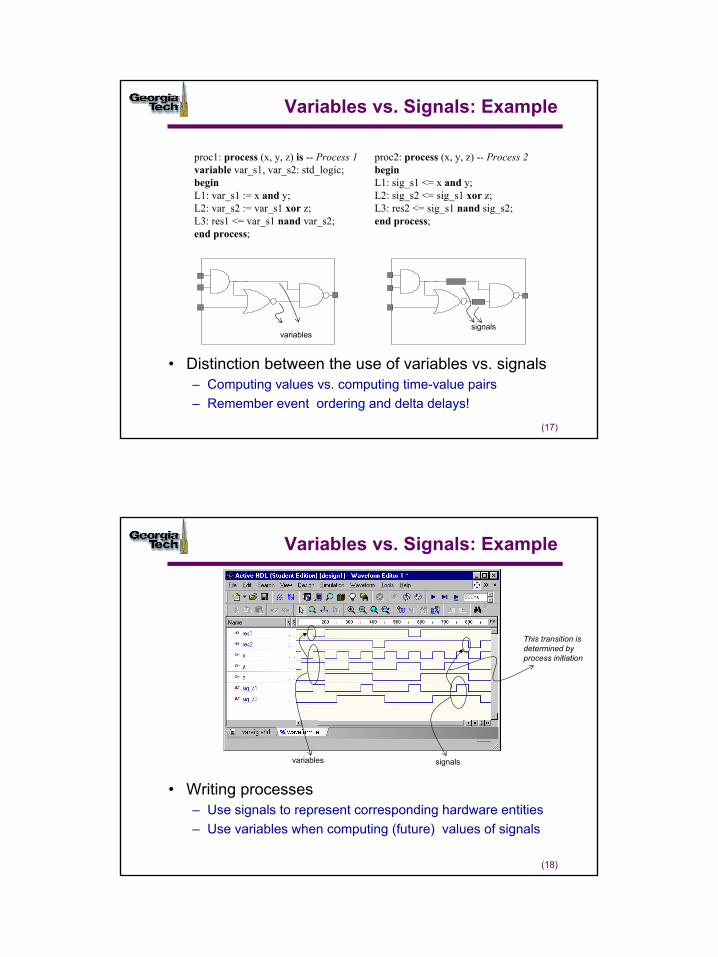
(16)
Process Behavior• All processes are executed once at start-up• Thereafter dependencies between signal values and events on
these signals determine process initiation• One can view processes as components with an
interface/function• Note that signals behave differently from variables!
library IEEE;use IEEE.std_logic_1164.all;
entity sig_var isport (x, y, z: in std_logic;res1, res2: out std_logic);end entity sig_var;
architecture behavior of sig_var issignal sig_s1, sig_s2: std_logic;beginproc1: process (x, y, z) is -- Process 1variable var_s1, var_s2: std_logic;
beginL1: var_s1 := x and y;L2: var_s2 := var_s1 xor z;L3: res1 <= var_s1 nand var_s2;end process;
proc2: process (x, y, z) -- Process 2beginL1: sig_s1 <= x and y;L2: sig_s2 <= sig_s1 xor z;L3: res2 <= sig_s1 nand sig_s2;end process;
end architecture behavior;
9
(17)
Variables vs. Signals: Example
proc1: process (x, y, z) is -- Process 1variable var_s1, var_s2: std_logic;beginL1: var_s1 := x and y;L2: var_s2 := var_s1 xor z;L3: res1 <= var_s1 nand var_s2;end process;
proc2: process (x, y, z) -- Process 2beginL1: sig_s1 <= x and y;L2: sig_s2 <= sig_s1 xor z;L3: res2 <= sig_s1 nand sig_s2;end process;
variablessignals
• Distinction between the use of variables vs. signals– Computing values vs. computing time-value pairs– Remember event ordering and delta delays!
(18)
Variables vs. Signals: Example
variables signals
• Writing processes– Use signals to represent corresponding hardware entities– Use variables when computing (future) values of signals
This transition is determined by process initiation
10
(19)
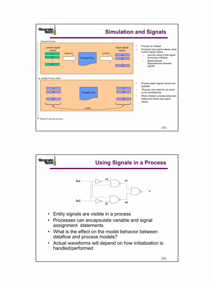
Simulation and Signals
Process Foo
s2 Process Foo
current signal values
future signal values
s1
s7
s2
s1
s7
s2
s1
s7
s2
s1
s7
update
• Process is initiated• Compute new signal values using
current signal values– Use the value of the signal
at process initiation– Ignore textual
dependencies between signals
• Process state (signal values) are updated
• Process now waits for an event on its sensitivity list
• When initiated, process execution references these new signal values
reference compute
Execute Process
Update Process State
Ready to execute process
(20)
Using Signals in a Process
• Entity signals are visible in a process• Processes can encapsulate variable and signal
assignment statements• What is the effect on the model behavior between
dataflow and process models?• Actual waveforms will depend on how initialization is
handled/performed
In1
In2
z
s1
s2
s3
s4
11
(21)
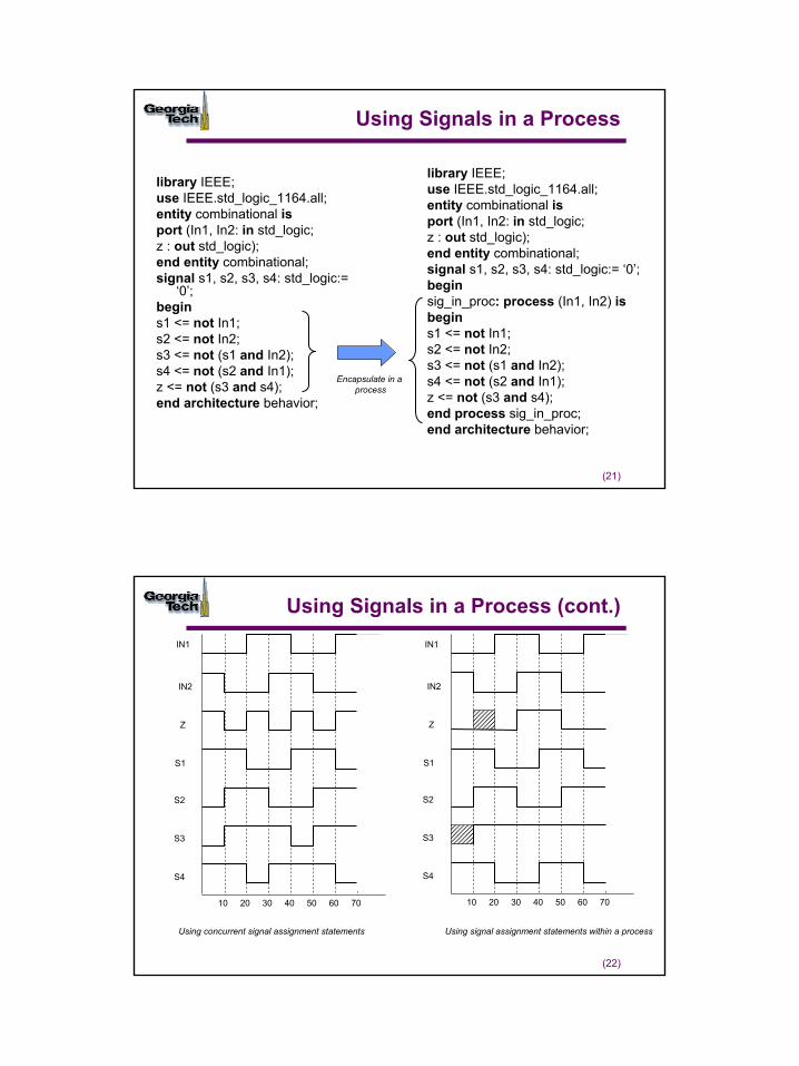
Using Signals in a Process
library IEEE;use IEEE.std_logic_1164.all;entity combinational isport (In1, In2: in std_logic;z : out std_logic);end entity combinational;signal s1, s2, s3, s4: std_logic:=
‘0’;begins1 <= not In1;s2 <= not In2;s3 <= not (s1 and In2);s4 <= not (s2 and In1);z <= not (s3 and s4);end architecture behavior;
library IEEE;use IEEE.std_logic_1164.all;entity combinational isport (In1, In2: in std_logic;z : out std_logic);end entity combinational;signal s1, s2, s3, s4: std_logic:= ‘0’;beginsig_in_proc: process (In1, In2) is begins1 <= not In1;s2 <= not In2;s3 <= not (s1 and In2);s4 <= not (s2 and In1);z <= not (s3 and s4);end process sig_in_proc;end architecture behavior;
Encapsulate in a process
(22)
Using Signals in a Process (cont.)IN1
IN2
Z
S1
S2
S3
S4
10 20 30 40 50 60 70
IN1
IN2
Z
S1
S2
S3
S4
10 20 30 40 50 60 70
Using concurrent signal assignment statements Using signal assignment statements within a process
12
(23)
Outline
• Abstraction and the Process Statement– Concurrent processes and CSAs
• Process event behavior and signals vs. variables
• Timing behavior of processes
• Attributes
• Putting it together modeling state machines
(24)
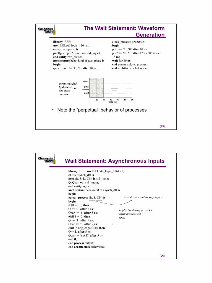
The Wait Statement
• The wait statements can describe synchronous or asynchronous timing operations
library IEEE;use IEEE.std_logic_1164.all;entity dff isport (D, Clk : in std_logic;Q, Qbar : out std_logic);end entity dff;architecture behavioral of dff isbeginoutput: process isbeginwait until (Clk’event and Clk = ‘1’); -- wait for rising edgeQ <= D after 5 ns;Qbar <= not D after 5 ns;end process output;end architecture behavioral;
signifies a value change on signal clk
13
(25)
The Wait Statement: Waveform Generation
reset
phi1
phi2
10 20 30 40 50 60Time (ns)
events specifiedby the resetand clock processes
library IEEE;use IEEE.std_logic_1164.all;entity two_phase isport(phi1, phi2, reset: out std_logic);end entity two_phase;architecture behavioral of two_phase isbeginrproc: reset <= ‘1’, ‘0’ after 10 ns;
clock_process: process isbeginphi1 <= ‘1’, ‘0’ after 10 ns;phi2 <= ‘0’, ‘1’ after 12 ns, ‘0’ after18 ns;wait for 20 ns;end process clock_process;end architecture behavioral;
• Note the “perpetual” behavior of processes
(26)
Wait Statement: Asynchronous Inputslibrary IEEE; use IEEE.std_logic_1164.all;entity asynch_dff isport (R, S, D, Clk: in std_logic;Q, Qbar: out std_logic);end entity asynch_dff;architecture behavioral of asynch_dff isbeginoutput: process (R, S, Clk) isbeginif (R = ‘0’) thenQ <= ‘0’ after 5 ns;Qbar <= ‘1’ after 5 ns;elsif S = ‘0’ thenQ <= ‘1’ after 5 ns;Qbar <= ‘0’ after 5 ns;elsif (rising_edge(Clk)) thenQ<= D after 5 ns;Qbar <= (not D) after 5 ns;end if;end process output;end architecture behavioral;
implied ordering providesasynchronous setreset
execute on event on any signal
14
(27)
The Wait Statement
• A process can have multiple wait statements
• A process cannot have both a wait statement and a sensitivity list (it should have one or the other): why?
• wait statements provide explicit control over suspension and resumption of processes– Representation of both synchronous and asynchronous events in a
digital systems
(28)
Outline
• Abstraction and the Process Statement– Concurrent processes and CSAs
• Process event behavior and signals vs. variables
• Timing behavior of processes
• Attributes
• Putting it together modeling state machines
15
(29)
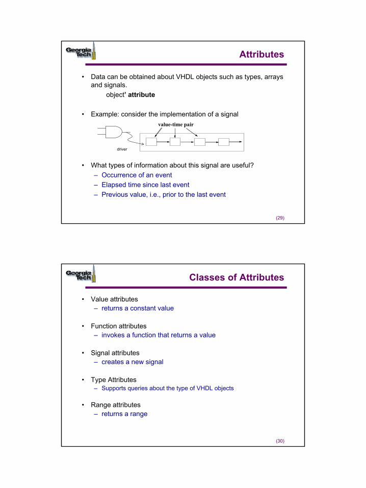
Attributes
• What types of information about this signal are useful?– Occurrence of an event– Elapsed time since last event– Previous value, i.e., prior to the last event
value-time pair
• Data can be obtained about VHDL objects such as types, arrays and signals.
object’ attribute
• Example: consider the implementation of a signal
driver
(30)
Classes of Attributes
• Value attributes– returns a constant value
• Function attributes– invokes a function that returns a value
• Signal attributes– creates a new signal
• Type Attributes– Supports queries about the type of VHDL objects
• Range attributes– returns a range
16
(31)
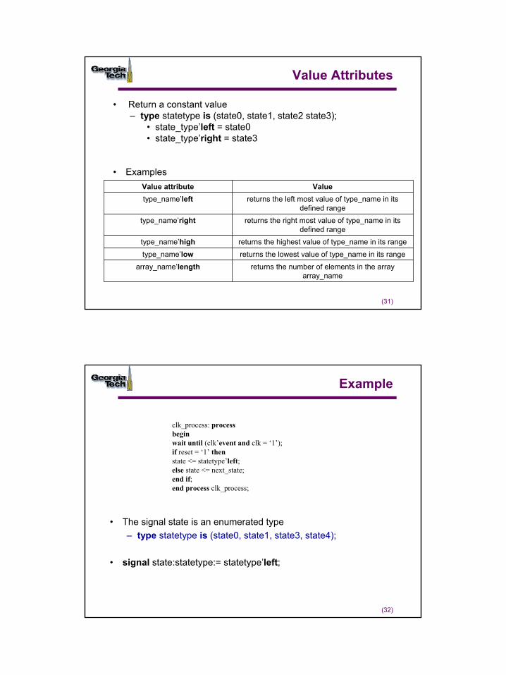
Value Attributes
• Return a constant value – type statetype is (state0, state1, state2 state3);
• state_type’left = state0• state_type’right = state3
• Examples
returns the number of elements in the array array_name
array_name’lengthreturns the lowest value of type_name in its rangetype_name’lowreturns the highest value of type_name in its rangetype_name’high
returns the right most value of type_name in its defined range
type_name’right
returns the left most value of type_name in its defined range
type_name’leftValueValue attribute
(32)
Example
• The signal state is an enumerated type– type statetype is (state0, state1, state3, state4);
• signal state:statetype:= statetype’left;
clk_process: processbeginwait until (clk’event and clk = ‘1’);if reset = ‘1’ thenstate <= statetype’left;else state <= next_state;end if;end process clk_process;
17
(33)
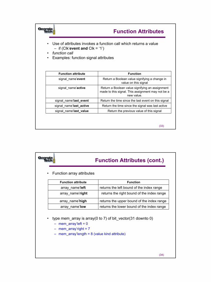
Function Attributes
• Use of attributes invokes a function call which returns a value – if (Clk’event and Clk = ‘1’)
• function call• Examples: function signal attributes
Return the previous value of this signal signal_name’last_valueReturn the time since the signal was last activesignal_name’last_active
Return the time since the last event on this signalsignal_name’last_event
Return a Boolean value signifying an assignment made to this signal. This assignment may not be a
new value.
signal_name’active
Return a Boolean value signifying a change in value on this signal
signal_name’eventFunctionFunction attribute
(34)
Function Attributes (cont.)
• Function array attributes
• type mem_array is array(0 to 7) of bit_vector(31 downto 0)– mem_array’left = 0– mem_array’right = 7– mem_array’length = 8 (value kind attribute)
returns the lower bound of the index rangearray_name’lowreturns the upper bound of the index rangearray_name’high
returns the right bound of the index rangearray_name’rightreturns the left bound of the index rangearray_name’left
FunctionFunction attribute
18
(35)
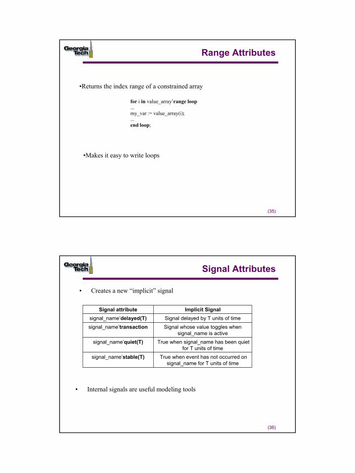
Range Attributes
for i in value_array’range loop...my_var := value_array(i);...end loop;
•Makes it easy to write loops
•Returns the index range of a constrained array
(36)
Signal Attributes
• Creates a new “implicit” signal
True when event has not occurred on signal_name for T units of time
signal_name’stable(T)
True when signal_name has been quiet for T units of time
signal_name’quiet(T)
Signal whose value toggles when signal_name is active
signal_name’transactionSignal delayed by T units of timesignal_name’delayed(T)
Implicit SignalSignal attribute
• Internal signals are useful modeling tools
19
(37)
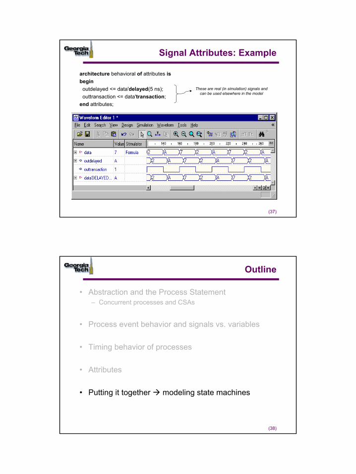
Signal Attributes: Example
architecture behavioral of attributes isbegin
outdelayed <= data'delayed(5 ns);outtransaction <= data'transaction;
end attributes;
These are real (in simulation) signals and can be used elsewhere in the model
(38)
Outline
• Abstraction and the Process Statement– Concurrent processes and CSAs
• Process event behavior and signals vs. variables
• Timing behavior of processes
• Attributes
• Putting it together modeling state machines
20
(39)
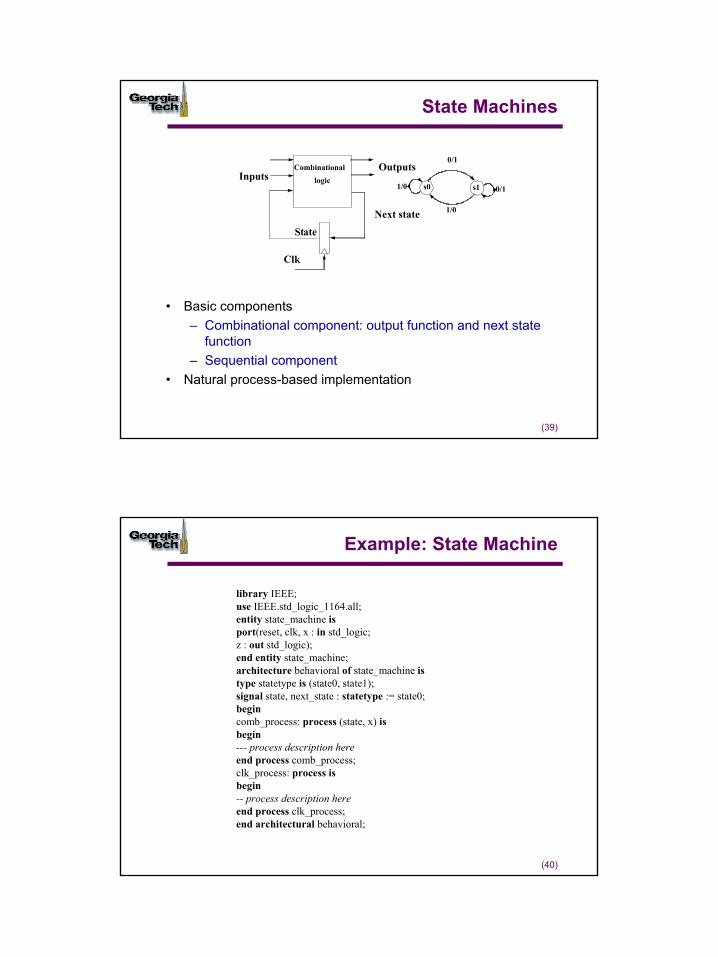
State Machines
• Basic components – Combinational component: output function and next state
function– Sequential component
• Natural process-based implementation
CombinationallogicInputs
Outputs
State
Clk
Next state
s0 s1 0/11/0
0/1
1/0
(40)
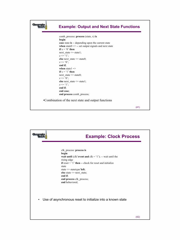
Example: State Machine
library IEEE;use IEEE.std_logic_1164.all;entity state_machine isport(reset, clk, x : in std_logic;z : out std_logic);end entity state_machine;architecture behavioral of state_machine istype statetype is (state0, state1);signal state, next_state : statetype := state0;begincomb_process: process (state, x) isbegin--- process description hereend process comb_process;clk_process: process isbegin-- process description hereend process clk_process;end architectural behavioral;
21
(41)
Example: Output and Next State Functions
•Combination of the next state and output functions
comb_process: process (state, x) isbegincase state is -- depending upon the current statewhen state0 => -- set output signals and next stateif x = ‘0’ thennext_state <= state1;z <= ‘1’;else next_state <= state0;z <= ‘0’;end if;when state1 =>if x = ‘1’ thennext_state <= state0;z <= ‘0’;else next_state <= state1;z <= ‘1’;end if;end case;end process comb_process;
(42)
Example: Clock Process
• Use of asynchronous reset to initialize into a known state
clk_process: process isbeginwait until (clk’event and clk = ‘1’); -- wait until the rising edgeif reset = ‘1’ then -- check for reset and initialize statestate <= statetype’left;else state <= next_state;end if;end process clk_process;end behavioral;
22
(43)
Summary
• Processes– variables and sequential statements– if-then, if-then-else, case, while, for– concurrent processes– sensitivity list
• The Wait statement – wait until, wait for, wait on
• Attributes• Modeling State machines
wait on ReceiveData’transactionif ReceiveData’delayed = ReceiveData then..
1
(1)
Modeling Structure
© Sudhakar Yalamanchili, Georgia Institute of Technology, 2006
(2)
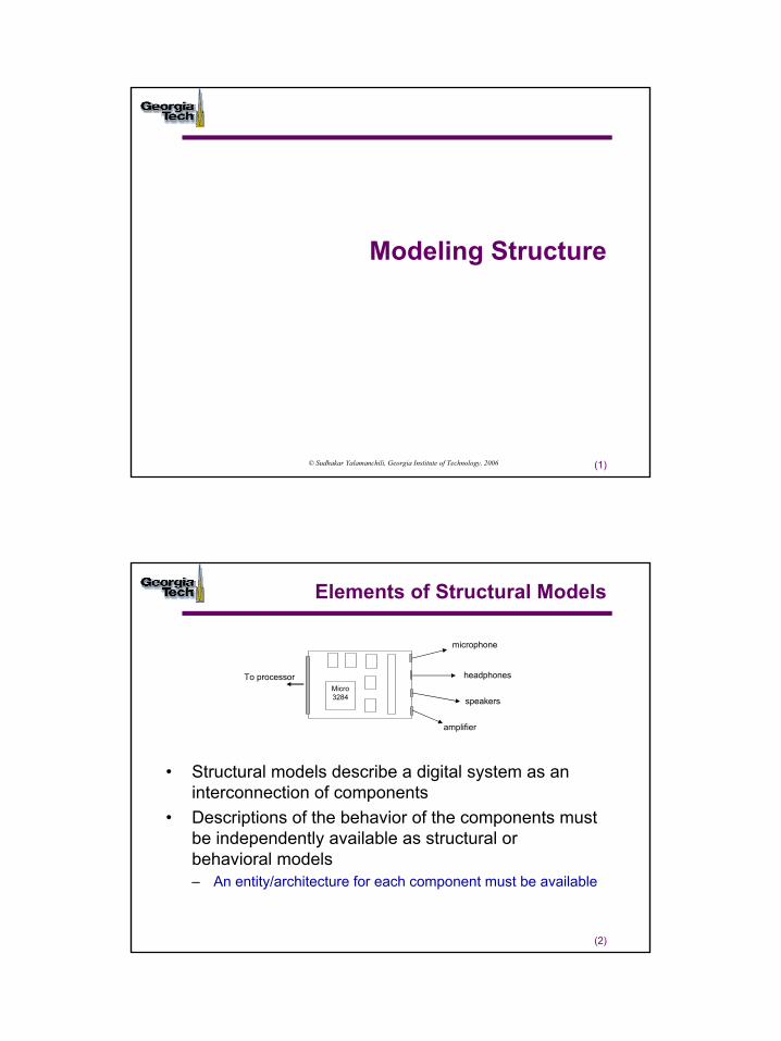
Elements of Structural Models
• Structural models describe a digital system as an interconnection of components
• Descriptions of the behavior of the components must be independently available as structural or behavioral models– An entity/architecture for each component must be available
Micro3284
To processor
microphone
speakers
headphones
amplifier
2
(3)
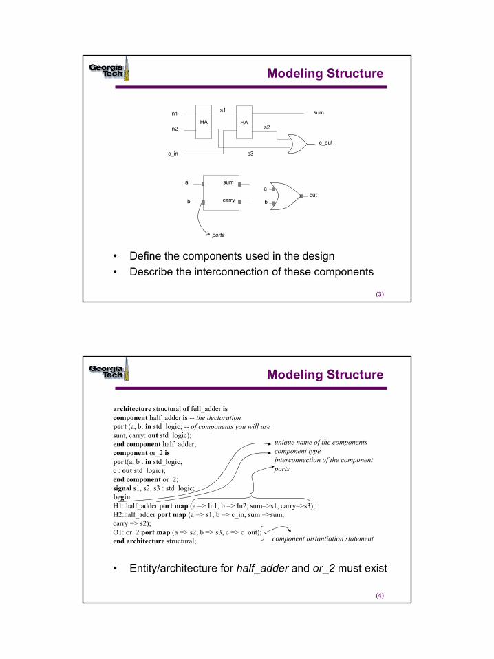
Modeling Structure
• Define the components used in the design• Describe the interconnection of these components
In1
ports
sum
carry
a
bout
HA HA
c_in
In2
sum
c_out
s2
s3
s1
a
b
(4)
Modeling Structure
• Entity/architecture for half_adder and or_2 must exist
architecture structural of full_adder iscomponent half_adder is -- the declarationport (a, b: in std_logic; -- of components you will usesum, carry: out std_logic);end component half_adder;component or_2 isport(a, b : in std_logic;c : out std_logic);end component or_2;signal s1, s2, s3 : std_logic;beginH1: half_adder port map (a => In1, b => In2, sum=>s1, carry=>s3);H2:half_adder port map (a => s1, b => c_in, sum =>sum,carry => s2);O1: or_2 port map (a => s2, b => s3, c => c_out);end architecture structural;
unique name of the componentscomponent typeinterconnection of the componentports
component instantiation statement
3
(5)
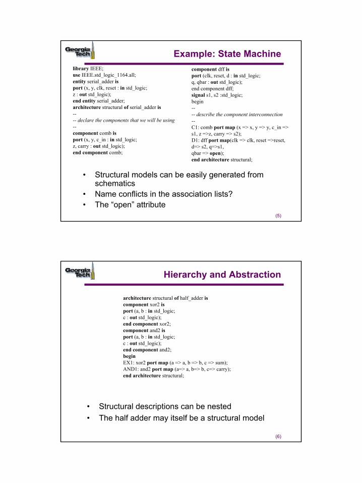
Example: State Machine
• Structural models can be easily generated from schematics
• Name conflicts in the association lists?• The “open” attribute
library IEEE;use IEEE.std_logic_1164.all;entity serial_adder isport (x, y, clk, reset : in std_logic;z : out std_logic);end entity serial_adder;architecture structural of serial_adder is---- declare the components that we will be using--component comb isport (x, y, c_in : in std_logic;z, carry : out std_logic);end component comb;
component dff isport (clk, reset, d : in std_logic;q, qbar : out std_logic);end component dff;signal s1, s2 :std_logic;begin---- describe the component interconnection--C1: comb port map (x => x, y => y, c_in =>s1, z =>z, carry => s2);D1: dff port map(clk => clk, reset =>reset,d=> s2, q=>s1,qbar => open);end architecture structural;
(6)
Hierarchy and Abstraction
• Structural descriptions can be nested• The half adder may itself be a structural model
architecture structural of half_adder iscomponent xor2 isport (a, b : in std_logic;c : out std_logic);end component xor2;component and2 isport (a, b : in std_logic;c : out std_logic);end component and2;beginEX1: xor2 port map (a => a, b => b, c => sum);AND1: and2 port map (a=> a, b=> b, c=> carry);end architecture structural;
4
(7)
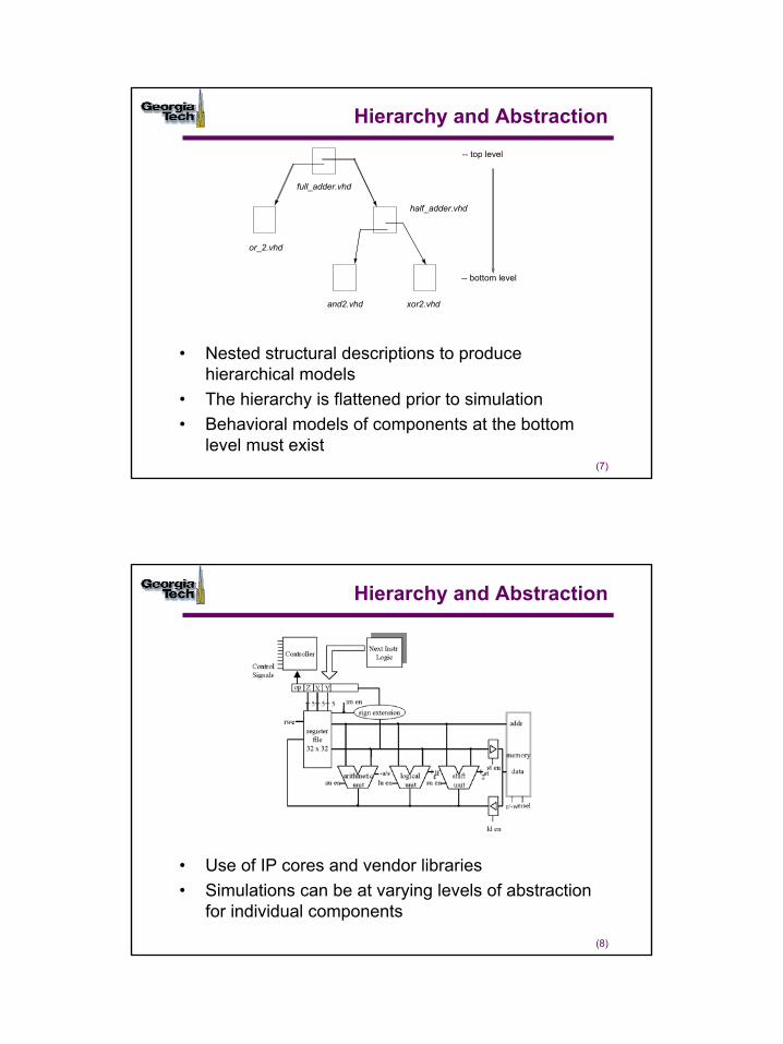
Hierarchy and Abstraction
• Nested structural descriptions to produce hierarchical models
• The hierarchy is flattened prior to simulation• Behavioral models of components at the bottom
level must exist
-- top level
-- bottom level
full_adder.vhd
half_adder.vhd
or_2.vhd
and2.vhd xor2.vhd
(8)
Hierarchy and Abstraction
• Use of IP cores and vendor libraries• Simulations can be at varying levels of abstraction
for individual components
5
(9)
Generics
• Enables the construction of parameterized models
library IEEE;use IEEE.std_logic_1164.all;
entity xor2 isgeneric (gate_delay : Time:= 2 ns);port(In1, In2 : in std_logic;z : out std_logic);end entity xor2;
architecture behavioral of xor2 isbeginz <= (In1 xor In2) after gate_delay;end architecture behavioral;
(10)
Generics in Hierarchical Models
• Parameter values are passed through the hierarchy
architecture generic_delay of half_adder iscomponent xor2generic (gate_delay: Time);port (a, b : in std_logic;c : out std_logic);end component;component and2generic (gate_delay: Time);port (a, b : in std_logic;c : out std_logic);end component;beginEX1: xor2 generic map (gate_delay => 6 ns)
port map(a => a, b => b, c => sum);A1: and2 generic map (gate_delay => 3 ns)
port map(a=> a, b=> b, c=> carry);end architecture generic_delay;
6
(11)
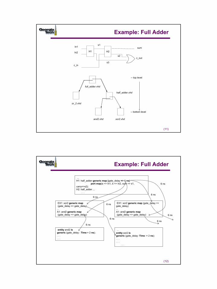
Example: Full Adder
H1 H2
In1
In2
c_in
sum
c_out
s1
s2
s3
-- top level
-- bottom level
full_adder.vhd
half_adder.vhd
or_2.vhd
and2.vhd xor2.vhd
(12)
Example: Full Adder
...H1: half_adder generic map (gate_delay => 6 ns)
port map(a => In1, b => In2, sum => s1, carry=>s2); H2: half_adder ...
. . .
EX1: xor2 generic map(gate_delay => gate_delay)
...A1: and2 generic map(gate_delay => gate_delay)
EX1: xor2 generic map (gate_delay => gate_delay)...A1: and2 generic map(gate_delay => gate_delay)
entity and2 isgeneric (gate_delay : Time:= 2 ns);. . . . . .
...entity xor2 isgeneric (gate_delay :Time := 2 ns); . . . . . .
. . .
6 ns
6 ns
6 ns
6 ns
6 ns
6 ns
6 ns
6 ns
7
(13)
Precedence of Generic Declarations
• Generic map takes precedence over the component declaration
architecture generic_delay2 of half_adder iscomponent xor2generic (gate_delay: Time);port(a,b : in std_logic;c : out std_logic);end component;
component and2generic (gate_delay: Time:= 6 ns);port (a, b : in std_logic;c : out std_logic);end component;
beginEX1: xor2 generic map (gate_delay => gate_delay)port map(a => a, b => b, c => sum);A1: and2 generic map (gate_delay => 4 ns)port map(a=> a, b=> b, c=> carry);end generic_delay2;
takes precedence
(14)
Generics: Properties
signal
signal
value
signal
VHDL Program
value
Design Entity
• Generics are constant objects and can only be read• The values of generics must be known at compile time• They are a part of the interface specification but do not have a
physical interpretation• Use of generics is not limited to “delay like” parameters and are
in fact a very powerful structuring mechanism
8
(15)
Example: N-Input Gate
• Map the generics to create different size OR gates
entity generic_or isgeneric (n: positive:=2);port (in1 : in std_logic_vector ((n-1) downto 0);z : out std_logic);end entity generic_or;architecture behavioral of generic_or isbeginprocess (in1) isvariable sum : std_logic:= ‘0’;beginsum := ‘0’; -- on an input signal transition sum must be resetfor i in 0 to (n-1) loopsum := sum or in1(i);end loop;z <= sum;end process;end architecture behavioral;
(16)
Example: Using the Generic N-Input OR Gate
• Full adder model can be modified to use the generic OR gate model via the generic map () construct
• Analogy with macros
architecture structural of full_adder iscomponent generic_orgeneric (n: positive);port (in1 : in std_logic_vector ((n-1) downto 0);z : out std_logic);end component;...... -- remainder of the declarative region from earlier example...beginH1: half_adder port map (a => In1, b => In2, sum=>s1, carry=>s3);H2:half_adder port map (a => s1, b => c_in, sum =>sum, carry => s2);O1: generic_or generic map (n => 2)
port map (a => s2, b => s3, c => c_out);end structural;
9
(17)
Example: N-bit Register
• This model is used in the same manner as the generic OR gate
entity generic_reg isgeneric (n: positive:=2);port ( clk, reset, enable : in std_logic;
d : in std_logic_vector (n-1 downto 0);q : out std_logic_vector (n-1 downto 0));
end entity generic_reg;architecture behavioral of generic_reg isbeginreg_process: process (clk, reset)beginif reset = ‘1’ then
q <= (others => ‘0’);elsif (rising_edge(clk)) then
if enable = ‘1’ then q <= d;end if;
end if;end process reg_process;end architecture behavioral;
(18)
Component Instantiation and Synthesis
• Design methodology for inclusion of highly optimized components or “cores”– Optimized in the sense of placed and routed– Intellectual property cores for sale– Check out http://www.xilinx.com/ipcenter/index.htm
• Core generators for static generation of cores– Generation of VHDL/Verilog models of placed and routed
designs– Component instantiation for using cores in a design
• Access to special components/circuitry within the target chip
10
(19)
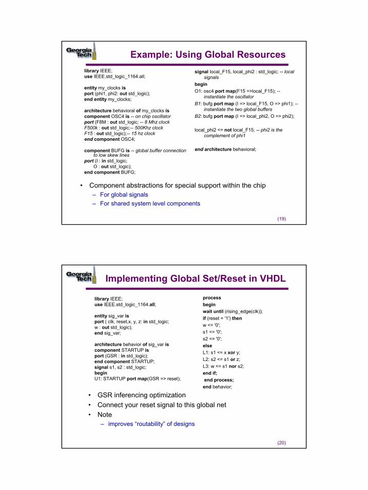
Example: Using Global Resourceslibrary IEEE;use IEEE.std_logic_1164.all;
entity my_clocks isport (phi1, phi2: out std_logic);end entity my_clocks;
architecture behavioral of my_clocks iscomponent OSC4 is -- on chip oscillatorport (F8M : out std_logic; -- 8 Mhz clockF500k : out std_logic;-- 500Khz clockF15 : out std_logic);-- 15 hz clockend component OSC4;
component BUFG is -- global buffer connection to low skew lines
port (I : in std_logic;O : out std_logic);
end component BUFG;
signal local_F15, local_phi2 : std_logic; -- local signals
beginO1: osc4 port map(F15 =>local_F15); --
instantiate the oscillatorB1: bufg port map (I => local_F15, O => phi1); --
instantiate the two global buffersB2: bufg port map (I => local_phi2, O => phi2);
local_phi2 <= not local_F15; -- phi2 is the complement of phi1
end architecture behavioral;
• Component abstractions for special support within the chip– For global signals– For shared system level components
(20)
Implementing Global Set/Reset in VHDL
library IEEE;use IEEE.std_logic_1164.all;
entity sig_var isport ( clk, reset,x, y, z: in std_logic;w : out std_logic);end sig_var;
architecture behavior of sig_var iscomponent STARTUP isport (GSR : in std_logic);end component STARTUP;signal s1, s2 : std_logic;beginU1: STARTUP port map(GSR => reset);
processbeginwait until (rising_edge(clk));if (reset = '1') thenw <= '0'; s1 <= '0';s2 <= '0';elseL1: s1 <= x xor y;L2: s2 <= s1 or z;L3: w <= s1 nor s2;end if;end process;
end behavior;
• GSR inferencing optimization• Connect your reset signal to this global net• Note
– improves “routability” of designs
11
(21)
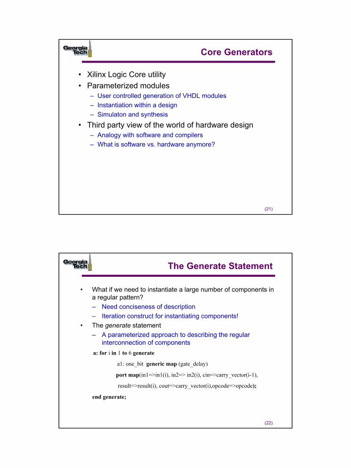
Core Generators
• Xilinx Logic Core utility• Parameterized modules
– User controlled generation of VHDL modules– Instantiation within a design– Simulaton and synthesis
• Third party view of the world of hardware design– Analogy with software and compilers– What is software vs. hardware anymore?
(22)
The Generate Statement
• What if we need to instantiate a large number of components in a regular pattern?– Need conciseness of description– Iteration construct for instantiating components!
• The generate statement– A parameterized approach to describing the regular
interconnection of componentsa: for i in 1 to 6 generate
a1: one_bit generic map (gate_delay)
port map(in1=>in1(i), in2=> in2(i), cin=>carry_vector(i-1),
result=>result(i), cout=>carry_vector(i),opcode=>opcode);
end generate;
12
(23)
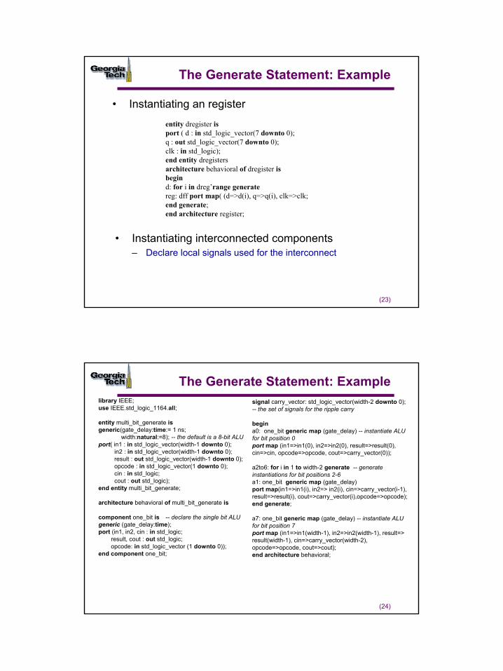
The Generate Statement: Example
• Instantiating interconnected components– Declare local signals used for the interconnect
entity dregister isport ( d : in std_logic_vector(7 downto 0);q : out std_logic_vector(7 downto 0);clk : in std_logic);end entity dregistersarchitecture behavioral of dregister isbegind: for i in dreg’range generatereg: dff port map( (d=>d(i), q=>q(i), clk=>clk;end generate;end architecture register;
• Instantiating an register
(24)
The Generate Statement: Examplelibrary IEEE;use IEEE.std_logic_1164.all;
entity multi_bit_generate isgeneric(gate_delay:time:= 1 ns;
width:natural:=8); -- the default is a 8-bit ALUport( in1 : in std_logic_vector(width-1 downto 0);
in2 : in std_logic_vector(width-1 downto 0);result : out std_logic_vector(width-1 downto 0);opcode : in std_logic_vector(1 downto 0);cin : in std_logic;cout : out std_logic);
end entity multi_bit_generate;
architecture behavioral of multi_bit_generate is
component one_bit is -- declare the single bit ALUgeneric (gate_delay:time);port (in1, in2, cin : in std_logic;
result, cout : out std_logic;opcode: in std_logic_vector (1 downto 0));
end component one_bit;
signal carry_vector: std_logic_vector(width-2 downto 0); -- the set of signals for the ripple carry
begina0: one_bit generic map (gate_delay) -- instantiate ALU for bit position 0 port map (in1=>in1(0), in2=>in2(0), result=>result(0), cin=>cin, opcode=>opcode, cout=>carry_vector(0));
a2to6: for i in 1 to width-2 generate -- generate instantiations for bit positions 2-6a1: one_bit generic map (gate_delay)port map(in1=>in1(i), in2=> in2(i), cin=>carry_vector(i-1), result=>result(i), cout=>carry_vector(i),opcode=>opcode);end generate;
a7: one_bit generic map (gate_delay) -- instantiate ALU for bit position 7port map (in1=>in1(width-1), in2=>in2(width-1), result=> result(width-1), cin=>carry_vector(width-2), opcode=>opcode, cout=>cout);end architecture behavioral;
13
(25)
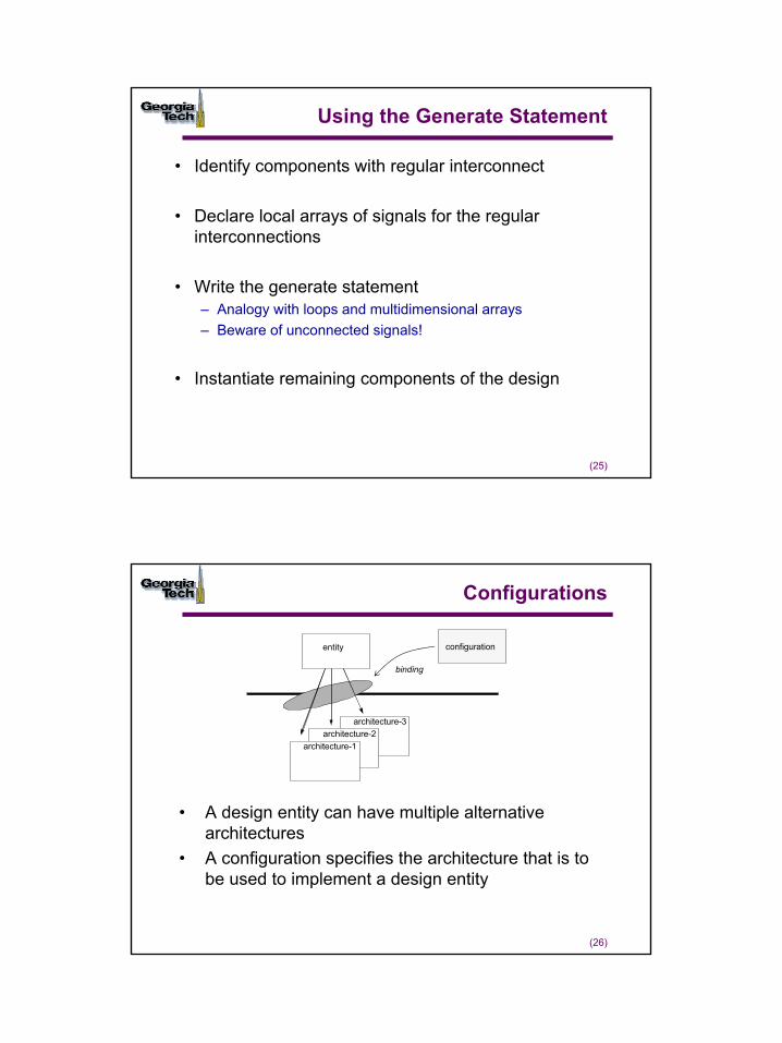
Using the Generate Statement
• Identify components with regular interconnect
• Declare local arrays of signals for the regular interconnections
• Write the generate statement– Analogy with loops and multidimensional arrays– Beware of unconnected signals!
• Instantiate remaining components of the design
(26)
Configurations
• A design entity can have multiple alternative architectures
• A configuration specifies the architecture that is to be used to implement a design entity
architecture-3architecture-2
architecture-1
entity
binding
configuration
14
(27)
Component Binding
• We are concerned with configuring the architecture and not the entity• Enhances sharing of designs: simply change the configuration
combinational logic
ab
z
carry
architecture gate_level of comb is
architecture behavioral of comb is
architecture low_power of comb is
architecture high_speed of comb is
Binding Information
D
Clk
Q
Q
R
(28)
Default Binding Rules
• Search for entity with the same component name• If multiple such entities exist, bind the last compiled
architecture for that entity• How do we get more control over binding?
architecture structural of serial_adder iscomponent comb isport (a, b, c_in : in std_logic;z, carry : out std_logic);end component comb;
component dff isport (clk, reset, d :in std_logic;q, qbar :out std_logic);end component dff;signal s1, s2 : std_logic;
beginC1: comb port map (a => a, b => b, c_in => s1, z =>z, carry => s2);D1: dff port map(clk => clk, reset =>reset, d=> s2, q=>s1, qbar =>open);end architecture structural;
15
(29)
Configuration Specification
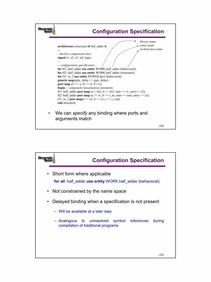
• We can specify any binding where ports and arguments match
architecture structural of full_adder is----declare components heresignal s1, s2, s3: std_logic;---- configuration specificationfor H1: half_adder use entity WORK.half_adder (behavioral);for H2: half_adder use entity WORK.half_adder (structural);for O1: or_2 use entity POWER.lpo2 (behavioral)generic map(gate_delay => gate_delay)port map (I1 => a, I2 => b, Z=>c);begin -- component instantiation statementsH1: half_adder port map (a =>In1, b => In2, sum => s1, carry=> s2);H2: half_adder port map (a => s1, b => c_in, sum => sum, carry => s2);O1: or_2 port map(a => s2, b => s3, c => c_out);end structural;
library nameentity namearchitecture name
(30)
Configuration Specification
• Short form where applicablefor all: half_adder use entity WORK.half_adder (behavioral);
• Not constrained by the name space
• Delayed binding when a specification is not present
– Will be available at a later step
– Analogous to unresolved symbol references during compilation of traditional programs
16
(31)
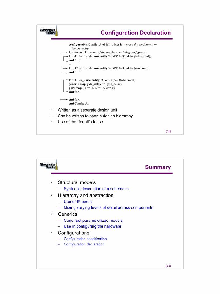
Configuration Declaration
• Written as a separate design unit• Can be written to span a design hierarchy• Use of the “for all” clause
configuration Config_A of full_adder is -- name the configuration-- for the entityfor structural -- name of the architecture being configuredfor H1: half_adder use entity WORK.half_adder (behavioral);end for;--for H2: half_adder use entity WORK.half_adder (structural);end for;--for O1: or_2 use entity POWER.lpo2 (behavioral)generic map(gate_delay => gate_delay)port map (I1 => a, I2 => b, Z=>c);end for;--end for;end Config_A;
(32)
Summary
• Structural models– Syntactic description of a schematic
• Hierarchy and abstraction– Use of IP cores– Mixing varying levels of detail across components
• Generics– Construct parameterized models– Use in configuring the hardware
• Configurations– Configuration specification– Configuration declaration
1
(1)
Subprograms, Packages, and Libraries
© Sudhakar Yalamanchili, Georgia Institute of Technology, 2006
(2)
Essentials of Functions
• Formal parameters and mode– Default mode is of type in
• Functions cannot modify parameters– Pure functions vs. impure functions
• Latter occur because of visibility into signals that are not parameters
• Function variables initialized on each call
function rising_edge (signal clock: std_logic) return boolean is----declarative region: declare variables local to the function--begin-- body--return (expression)end rising_edge;
2
(3)
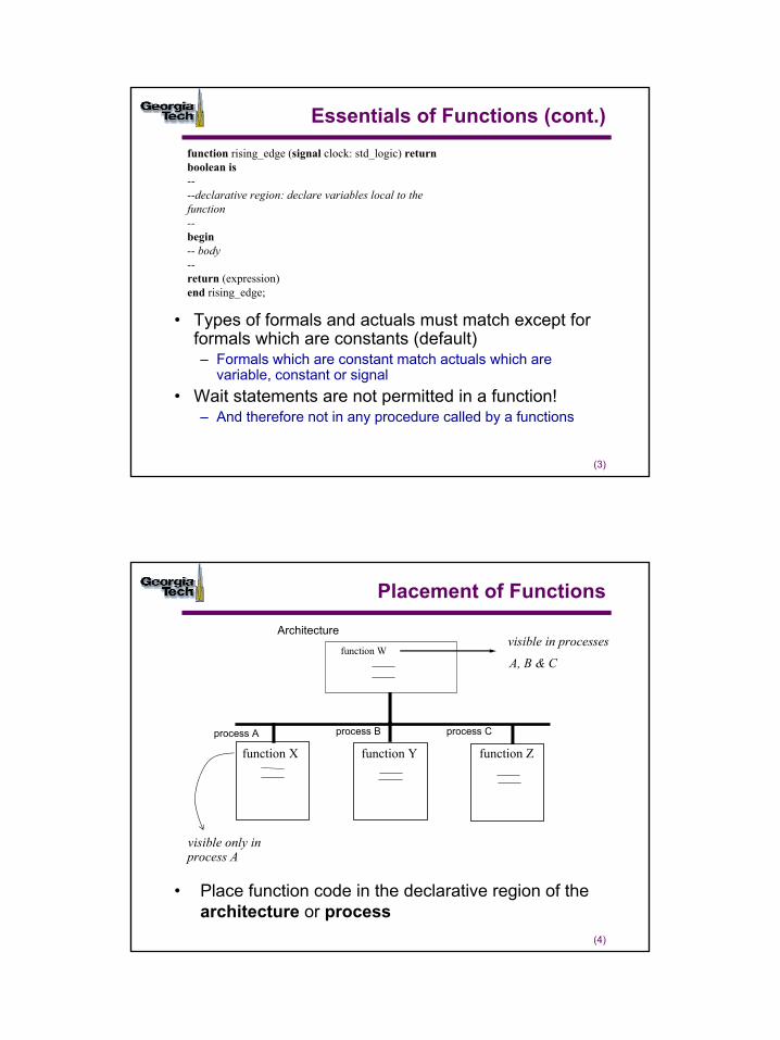
Essentials of Functions (cont.)
• Types of formals and actuals must match except for formals which are constants (default)– Formals which are constant match actuals which are
variable, constant or signal• Wait statements are not permitted in a function!
– And therefore not in any procedure called by a functions
function rising_edge (signal clock: std_logic) return boolean is----declarative region: declare variables local to the function--begin-- body--return (expression)end rising_edge;
(4)
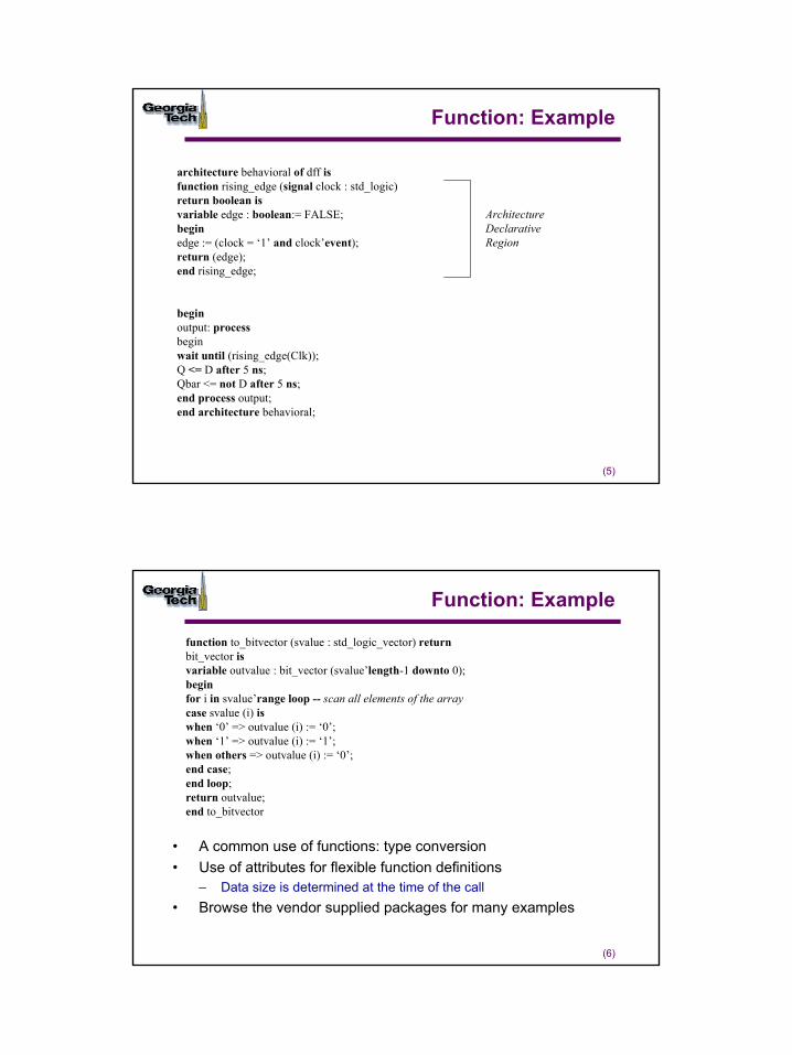
Placement of Functions
• Place function code in the declarative region of the architecture or process
process A process B process C
function X function Y function Z
function W
Architecturevisible in processes
A, B & C
visible only inprocess A
3
(5)
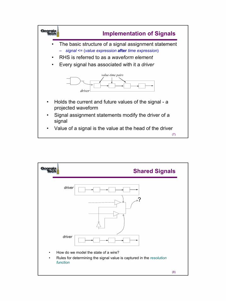
Function: Example
architecture behavioral of dff isfunction rising_edge (signal clock : std_logic) return boolean isvariable edge : boolean:= FALSE;beginedge := (clock = ‘1’ and clock’event);return (edge);end rising_edge;
beginoutput: processbeginwait until (rising_edge(Clk));Q <= D after 5 ns;Qbar <= not D after 5 ns;end process output;end architecture behavioral;
ArchitectureDeclarativeRegion
(6)
Function: Example
function to_bitvector (svalue : std_logic_vector) return bit_vector isvariable outvalue : bit_vector (svalue’length-1 downto 0);beginfor i in svalue’range loop -- scan all elements of the arraycase svalue (i) iswhen ‘0’ => outvalue (i) := ‘0’;when ‘1’ => outvalue (i) := ‘1’;when others => outvalue (i) := ‘0’;end case;end loop;return outvalue;end to_bitvector
• A common use of functions: type conversion• Use of attributes for flexible function definitions
– Data size is determined at the time of the call• Browse the vendor supplied packages for many examples
4
(7)
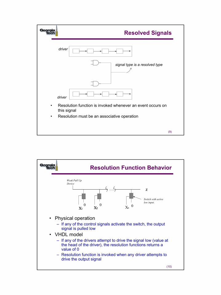
Implementation of Signals
• The basic structure of a signal assignment statement– signal <= (value expression after time expression)
• RHS is referred to as a waveform element• Every signal has associated with it a driver
• Holds the current and future values of the signal - a projected waveform
• Signal assignment statements modify the driver of a signal
• Value of a signal is the value at the head of the driver
value-time pairs
driver
(8)
Shared Signals
• How do we model the state of a wire?• Rules for determining the signal value is captured in the resolution
function
driver
driver
?
5
(9)
Resolved Signals
• Resolution function is invoked whenever an event occurs on this signal
• Resolution must be an associative operation
driver
driver
signal type is a resolved type
(10)
Resolution Function Behavior
• Physical operation– If any of the control signals activate the switch, the output
signal is pulled low• VHDL model
– If any of the drivers attempt to drive the signal low (value at the head of the driver), the resolution functions returns a value of 0
– Resolution function is invoked when any driver attempts to drive the output signal
X1 X2X1 X2 Xn
. . . Z. . . Z
Switch with activelow input.
Weak Pull UpDevice
000
6
(11)
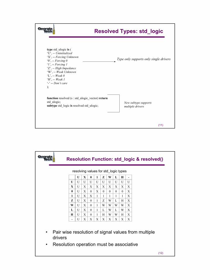
Resolved Types: std_logic
type std_ulogic is (‘U’, -- Uninitialized‘X’, -- Forcing Unknown‘0’, -- Forcing 0‘1’, -- Forcing 1‘Z’, -- High Impedance‘W’, -- Weak Unknown‘L’, -- Weak 0‘H’, -- Weak 1‘-’ -- Don’t care);
function resolved (s : std_ulogic_vector) returnstd_ulogic;subtype std_logic is resolved std_ulogic;
Type only supports only single drivers
New subtype supports multiple drivers
(12)
Resolution Function: std_logic & resolved()
• Pair wise resolution of signal values from multiple drivers
• Resolution operation must be associative
resolving values for std_logic types
U X 0 1 Z W L H -U U U U U U U U U UX U X X X X X X X X0 U X 0 X 0 0 0 0 X1 U X X 1 1 1 1 1 XZ U X 0 1 Z W L H XW U X 0 1 W W W W XL U X 0 1 L W L W XH U X 0 1 H W W H X- U X X X X X X X X
7
(13)
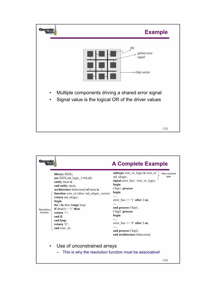
Example
• Multiple components driving a shared error signal• Signal value is the logical OR of the driver values
die
global errorsignal
chip carrier
(14)
A Complete Example
• Use of unconstrained arrays – This is why the resolution function must be associative!
library IEEE;use IEEE.std_logic_1164.all;entity mcm isend entity mcm;architecture behavioral of mcm isfunction wire_or (sbus :std_ulogic_vector)return std_ulogic;beginfor i in sbus’range loopif sbus(i) = ‘1’ thenreturn ‘1’;end if;end loop;return ‘0’;end wire_or;
subtype wire_or_logic is wire_orstd_ulogic;signal error_bus : wire_or_logic;beginChip1: processbegin--..error_bus <= ‘1’ after 2 ns;--..end process Chip1;Chip2: processbegin--..error_bus <= ‘0’ after 2 ns;--..end process Chip2;end architecture behavioral;
Resolution function
New resolved type
8
(15)
Summary: Essentials of Functions
• Placement of functions– Visibility
• Formal parameters– Actuals can have widths bound at the call time
• Check the source listings of packages for examples of many different functions
(16)
Essentials of Procedures
• Parameters may be of mode in (read only) and out (write only)
• Default class of input parameters is constant• Default class of output parameters is variable• Variables declared within procedure are initialized
on each call
procedure read_v1d (variable f: in text; v :out std_logic_vector)--declarative region: declare variables local to the procedure--begin-- body--end read_v1d;
9
(17)
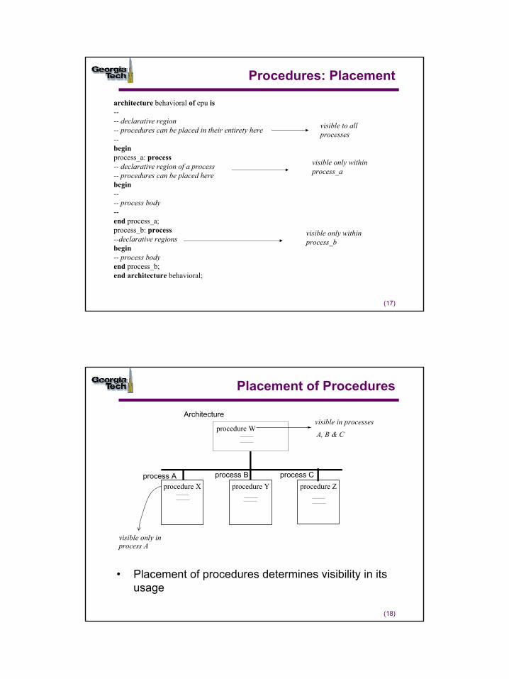
Procedures: Placement
architecture behavioral of cpu is---- declarative region-- procedures can be placed in their entirety here--beginprocess_a: process-- declarative region of a process-- procedures can be placed herebegin---- process body--end process_a;process_b: process--declarative regionsbegin-- process bodyend process_b;end architecture behavioral;
visible to allprocesses
visible only withinprocess_a
visible only withinprocess_b
(18)
Placement of Procedures
• Placement of procedures determines visibility in its usage
process A process B process Cprocedure X procedure Y procedure Z
procedure W
Architecturevisible in processes
A, B & C
visible only inprocess A
10
(19)
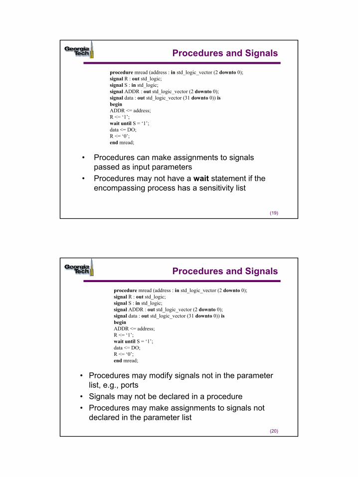
Procedures and Signals
• Procedures can make assignments to signals passed as input parameters
• Procedures may not have a wait statement if the encompassing process has a sensitivity list
procedure mread (address : in std_logic_vector (2 downto 0);signal R : out std_logic;signal S : in std_logic;signal ADDR : out std_logic_vector (2 downto 0);signal data : out std_logic_vector (31 downto 0)) isbeginADDR <= address;R <= ‘1’;wait until S = ‘1’;data <= DO;R <= ‘0’;end mread;
(20)
Procedures and Signals
• Procedures may modify signals not in the parameter list, e.g., ports
• Signals may not be declared in a procedure• Procedures may make assignments to signals not
declared in the parameter list
procedure mread (address : in std_logic_vector (2 downto 0);signal R : out std_logic;signal S : in std_logic;signal ADDR : out std_logic_vector (2 downto 0);signal data : out std_logic_vector (31 downto 0)) isbeginADDR <= address;R <= ‘1’;wait until S = ‘1’;data <= DO;R <= ‘0’;end mread;
11
(21)
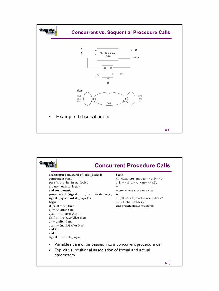
Concurrent vs. Sequential Procedure Calls
• Example: bit serial adder
ab
z
carry
00/001/110/1
01/010/011/1
11/0
00/1
D
Clk
Q
Q
R
ab/s
0 1
Combinational Logic
(22)
Concurrent Procedure Callsarchitecture structural of serial_adder iscomponent combport (a, b, c_in : in std_logic;z, carry : out std_logic);end component;procedure dff(signal d, clk, reset : in std_logic;signal q, qbar : out std_logic) isbeginif (reset = ‘0’) thenq <= ‘0’ after 5 ns;qbar <= ‘1’ after 5 ns;elsif (rising_edge(clk)) thenq <= d after 5 ns;qbar <= (not D) after 5 ns;end if;end dff;signal s1, s2 : std_logic;
beginC1: comb port map (a => a, b => b,c_in => s1, z =>z, carry => s2);---- concurrent procedure call--dff(clk => clk, reset =>reset, d=> s2,q=>s1, qbar =>open);end architectural structural;
• Variables cannot be passed into a concurrent procedure call• Explicit vs. positional association of formal and actual
parameters
12
(23)
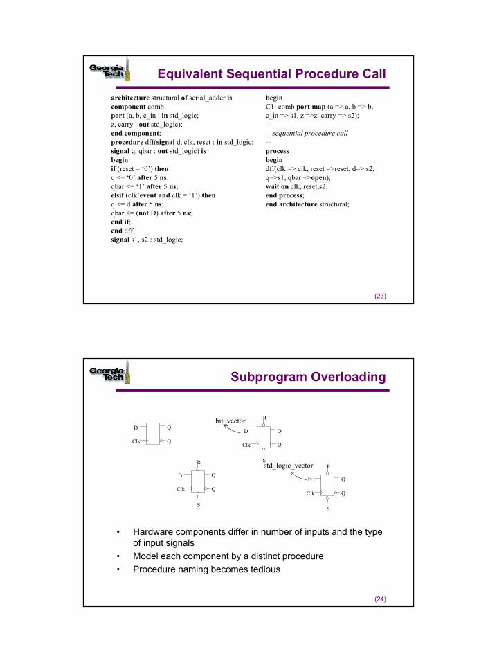
Equivalent Sequential Procedure Callarchitecture structural of serial_adder iscomponent combport (a, b, c_in : in std_logic;z, carry : out std_logic);end component;procedure dff(signal d, clk, reset : in std_logic;signal q, qbar : out std_logic) isbeginif (reset = ‘0’) thenq <= ‘0’ after 5 ns;qbar <= ‘1’ after 5 ns;elsif (clk’event and clk = ‘1’) thenq <= d after 5 ns;qbar <= (not D) after 5 ns;end if;end dff;signal s1, s2 : std_logic;
beginC1: comb port map (a => a, b => b,c_in => s1, z =>z, carry => s2);---- sequential procedure call--processbegindff(clk => clk, reset =>reset, d=> s2,q=>s1, qbar =>open);wait on clk, reset,s2;end process;end architecture structural;
(24)
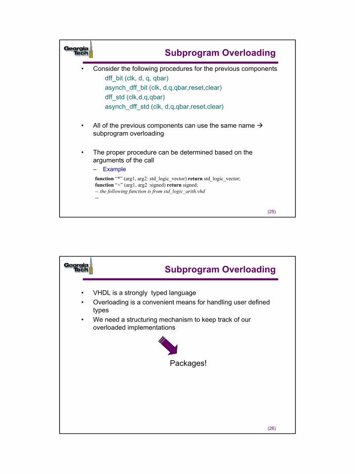
Subprogram Overloading
• Hardware components differ in number of inputs and the type of input signals
• Model each component by a distinct procedure• Procedure naming becomes tedious
D
Clk
Q
Q
D
Clk
S
Q
R
Q
D
Clk
S
Q
R
Q
D
Clk
S
Q
R
Q
bit_vector
std_logic_vector
13
(25)
Subprogram Overloading• Consider the following procedures for the previous components
dff_bit (clk, d, q, qbar)asynch_dff_bit (clk, d,q,qbar,reset,clear)dff_std (clk,d,q,qbar)asynch_dff_std (clk, d,q,qbar,reset,clear)
• All of the previous components can use the same name subprogram overloading
• The proper procedure can be determined based on the arguments of the call– Example function “*” (arg1, arg2: std_logic_vector) return std_logic_vector;function “+” (arg1, arg2 :signed) return signed;-- the following function is from std_logic_arith.vhd--
(26)
Subprogram Overloading
• VHDL is a strongly typed language• Overloading is a convenient means for handling user defined
types• We need a structuring mechanism to keep track of our
overloaded implementations
Packages!
14
(27)
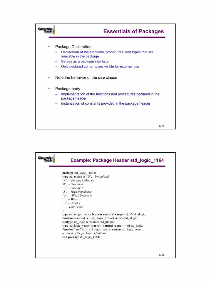
Essentials of Packages
• Package Declaration– Declaration of the functions, procedures, and types that are
available in the package– Serves as a package interface– Only declared contents are visible for external use
• Note the behavior of the use clause
• Package body– Implementation of the functions and procedures declared in the
package header– Instantiation of constants provided in the package header
(28)
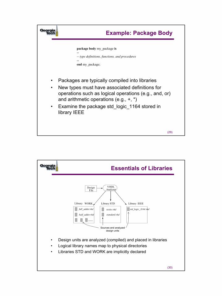
Example: Package Header std_logic_1164
package std_logic_1164 istype std_ulogic is (‘U’, --Unitialized‘X’, -- Forcing Unknown‘0’, -- Forcing 0‘1’, -- Forcing 1‘Z’, -- High Impedance‘W’, -- Weak Unknown‘L’, -- Weak 0‘H’, -- Weak 1‘-’ -- Don’t care);type std_ulogic_vector is array (natural range <>) of std_ulogic;function resolved (s : std_ulogic_vector) return std_ulogic;subtype std_logic is resolved std_ulogic;type std_logic_vector is array (natural range <>) of std_logic;function “and” (l, r : std_logic_vector) return std_logic_vector;--..<rest of the package definition>end package std_logic_1164;
15
(29)
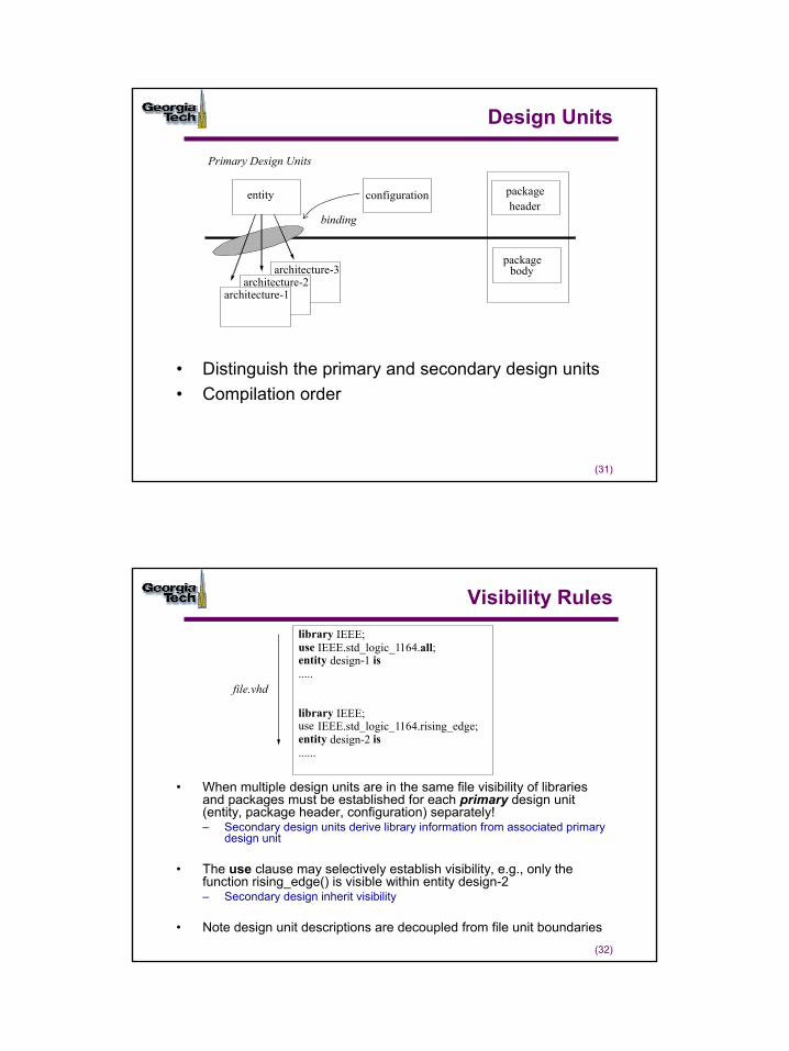
Example: Package Body
• Packages are typically compiled into libraries• New types must have associated definitions for
operations such as logical operations (e.g., and, or) and arithmetic operations (e.g., +, *)
• Examine the package std_logic_1164 stored in library IEEE
package body my_package is---- type definitions, functions, and procedures--end my_package;
(30)
Essentials of Libraries
• Design units are analyzed (compiled) and placed in libraries• Logical library names map to physical directories• Libraries STD and WORK are implicitly declared
DesignFile
VHDLAnalyzer
WORK STD IEEE
standard.vhd
std_logic_1164.vhdtextio.vhd
LibraryLibrary Library
full_adder.vhd
half_adder. vhd
.....
Sources and analyzed design units
16
(31)
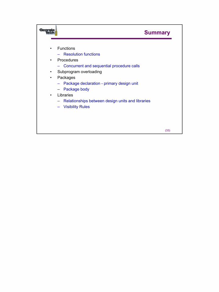
Design Units
• Distinguish the primary and secondary design units • Compilation order
architecture-3architecture-2
architecture-1
entity configuration packageheader
package body
binding
Primary Design Units
(32)
Visibility Rules
• When multiple design units are in the same file visibility of libraries and packages must be established for each primary design unit (entity, package header, configuration) separately!– Secondary design units derive library information from associated primary
design unit
• The use clause may selectively establish visibility, e.g., only the function rising_edge() is visible within entity design-2– Secondary design inherit visibility
• Note design unit descriptions are decoupled from file unit boundaries
library IEEE;use IEEE.std_logic_1164.all;entity design-1 is.....
library IEEE;use IEEE.std_logic_1164.rising_edge;entity design-2 is......
file.vhd
17
(33)
Summary
• Functions– Resolution functions
• Procedures– Concurrent and sequential procedure calls
• Subprogram overloading• Packages
– Package declaration - primary design unit– Package body
• Libraries– Relationships between design units and libraries– Visibility Rules
1
(1)
Basic Input and Output
© Sudhakar Yalamanchili, Georgia Institute of Technology, 2006
(2)
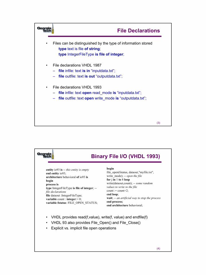
File Objects
• VHDL objects– signals– variables– constants– Files
• The file type permits us to declare and use file objects
VHDL Program
file:type declarationoperations
2
(3)
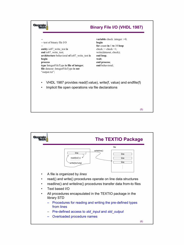
File Declarations
• Files can be distinguished by the type of information stored type text is file of string;type IntegerFileType is file of integer;
• File declarations VHDL 1987– file infile: text is in “inputdata.txt”;– file outfile: text is out “outputdata.txt”;
• File declarations VHDL 1993– file infile: text open read_mode is “inputdata.txt”;– file outfile: text open write_mode is “outputdata.txt”;
(4)
Binary File I/O (VHDL 1993)
• VHDL provides read(f,value), write(f, value) and endfile(f)• VHDL 93 also provides File_Open() and File_Close()• Explicit vs. implicit file open operations
entity io93 is -- this entity is emptyend entity io93;architecture behavioral of io93 isbeginprocess istype IntegerFileType is file of integer; --file declarationsfile dataout :IntegerFileType;variable count : integer:= 0;variable fstatus: FILE_OPEN_STATUS;
beginfile_open(fstatus, dataout,"myfile.txt",write_mode); -- open the filefor j in 1 to 8 loopwrite(dataout,count); -- some randomvalues to write to the filecount := count+2;end loop;wait; -- an artificial way to stop the processend process;end architecture behavioral;
3
(5)
Binary File I/O (VHDL 1987)
• VHDL 1987 provides read(f,value), write(f, value) and endfile(f)• Implicit file open operations via file declarations
---- test of binary file I/O--entity io87_write_test isend io87_write_test;architecture behavioral of io87_write_test isbeginprocesstype IntegerFileType is file of integer;file dataout :IntegerFileType is out“output.txt”;
variable check :integer :=0;beginfor count in 1 to 10 loopcheck := check +1;write(dataout, check);end loop;wait;end process;end behavioral;
(6)
The TEXTIO Package
• A file is organized by lines• read() and write() procedures operate on line data structures• readline() and writeline() procedures transfer data from-to files• Text based I/O• All procedures encapsulated in the TEXTIO package in the
library STD– Procedures for reading and writing the pre-defined types
from lines– Pre-defined access to std_input and std_output– Overloaded procedure names
line line
line
line
file
read(buf,c)
write(buf,arg)
writeline()
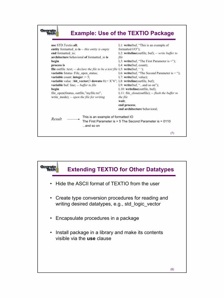
4
(7)
Example: Use of the TEXTIO Package
use STD.Textio.all;entity formatted_io is -- this entity is emptyend formatted_io;architecture behavioral of formatted_io isbeginprocess isfile outfile :text; -- declare the file to be a text filevariable fstatus :File_open_status;variable count: integer := 5;variable value : bit_vector(3 downto 0):= X”6”;variable buf: line; -- buffer to filebeginfile_open(fstatus, outfile,”myfile.txt”,write_mode); -- open the file for writing
L1: write(buf, “This is an example offormatted I/O”);L2: writeline(outfile, buf); -- write buffer tofileL3: write(buf, “The First Parameter is =”);L4: write(buf, count);L5: write(buf, ‘ ‘);L6: write(buf, “The Second Parameter is = “);L7: write(buf, value);L8: writeline(outfile, buf);L9: write(buf, “...and so on”);L10: writeline(outfile, buf);L11: file_close(outfile); -- flush the buffer tothe filewait;end process;end architecture behavioral;
This is an example of formatted IOThe First Parameter is = 5 The Second Parameter is = 0110...and so on
Result
(8)
Extending TEXTIO for Other Datatypes
• Hide the ASCII format of TEXTIO from the user
• Create type conversion procedures for reading and writing desired datatypes, e.g., std_logic_vector
• Encapsulate procedures in a package
• Install package in a library and make its contents visible via the use clause
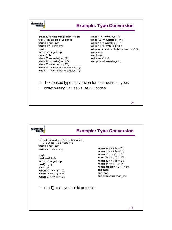
5
(9)
Example: Type Conversion
• Text based type conversion for user defined types• Note: writing values vs. ASCII codes
procedure write_v1d (variable f: out text; v : in std_logic_vector) isvariable buf: line;variable c : character;beginfor i in v’range loopcase v(i) iswhen ‘X’ => write(buf, ‘X’);when ‘U’ => write(buf, ‘U’);when ‘Z’ => write(buf, ‘Z’);when ‘0’ => write(buf, character’(‘0’));when ‘1’ => write(buf, character’(‘1’));
when ‘-’ => write(buf, ‘-’);when ‘W’ => write(buf, ‘W’);when ‘L’ => write(buf, ‘L’);when ‘H’ => write(buf, ‘H’);when others => write(buf, character’(‘0’));end case;end loop;writeline (f, buf);end procedure write_v1d;
(10)
Example: Type Conversion
procedure read_v1d (variable f:in text; v : out std_logic_vector) is
variable buf: line;variable c : character;
beginreadline(f, buf);for i in v’range loopread(buf, c); case c iswhen ‘X’ => v (i) := ‘X’;when ‘U’ => v (i) := ‘U’;when ‘Z’ => v (i) := ‘Z’;
when ‘0’ => v (i) := ‘0’;when ‘1’ => v (i) := ‘1’;when ‘-’ => v (i) := ‘-’;when ‘W’ => v (i) := ‘W’;when ‘L’ => v (i) := ‘L’;when ‘H’ => v (i) := ‘H’;when others => v (i) := ‘0’;end case;end loop;end procedure read_v1d
• read() is a symmetric process
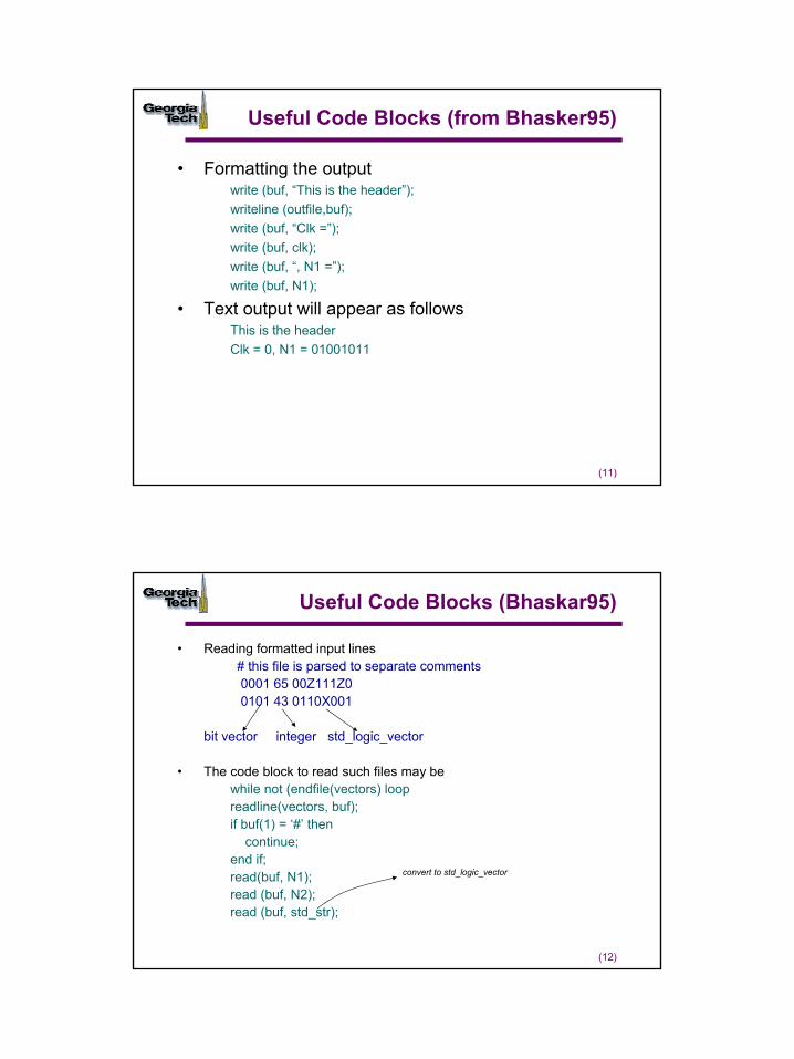
6
(11)
Useful Code Blocks (from Bhasker95)
• Formatting the outputwrite (buf, “This is the header”);writeline (outfile,buf);write (buf, “Clk =”);write (buf, clk);write (buf, “, N1 =”);write (buf, N1);
• Text output will appear as follows This is the headerClk = 0, N1 = 01001011
(12)
Useful Code Blocks (Bhaskar95)
• Reading formatted input lines# this file is parsed to separate comments0001 65 00Z111Z00101 43 0110X001
bit vector integer std_logic_vector
• The code block to read such files may be while not (endfile(vectors) loopreadline(vectors, buf);if buf(1) = ‘#’ then
continue;end if;read(buf, N1);read (buf, N2);read (buf, std_str);
convert to std_logic_vector

7
(13)
Useful Code Blocks: Filenames
process isvariable buf : line;variable fname : string(1 to 10);begin---- prompt and read filename from standard input--write(output, “Enter Filename: “);readline(input,buf);read(buf, fname);---- process code--end process;
• Assuming “input” is mapped to simulator console– Generally “input” and “output” are mapped to standard input
and standard output respectively
(14)
Useful Code Blocks: Testing Models
library IEEE;
use IEEE.std_logic_1164.all;use STD.textio.all;use Work.classio.all; -- the package classio has been compiled into the working directory
entity checking is end checking; -- the entity is an empty entity
architecture behavioral of checking is begin
-- use file I/O to read test vectors and write test results
end architecture behavioral; Testing process
my I/O library

8
(15)
Useful Code Blocks: Testing Models (cont.)
process is -- use implicit file open--file infile : TEXT open read_mode is "infile.txt";file outfile : TEXT open write_mode is "outfile.txt";variable check : std_logic_vector (15 downto 0) := x"0008";begin-- copy the input file contents to the output filewhile not (endfile (infile)) loop read_v1d (infile, check);----write_v1d (outfile, check);end loop;file_close(outfile); -- flush buffers to output filewait; -- artificial wait for this exampleend process;end architecture behavioral;
Can have a model here to test
Example: Usually will not have this in your models
(16)
Testbenches
ModelunderTest
Tester
Testbench output port
input porttester. vhd model.vhd
testbench.vhd
• Testbenches are transportable• General approach: apply stimulus vectors and
measure and record response vectors• Application of predicates establish correct operation
of the model under test
9
(17)
Example
•Tester module to generate periodic signals and apply test vectors
library IEEE;use IEEE.std_logic_1164.all;use STD.textio.all;use WORK.classio.all; -- declare the I/O packageentity srtester is -- this is the module generating the testsport (R, S, D, Clk : out std_logic;Q, Qbar : in std_logic);end entity srtester;architecture behavioral of srtester isbeginclk_process: process -- generates the clock waveform withbegin -- period of 20 nsClk<= ‘1’, ‘0’ after 10 ns, ‘1’ after 20 ns, ‘0’ after 30 ns;wait for 40 ns;end process clk_process;
(18)
Example (cont.)
Example (cont.)io_process: process -- this process performs the testfile infile : TEXT is in “infile.txt”; -- functionsfile outfile : TEXT is out “outfile.txt”;variable buf : line;variable msg : string(1 to 19) := “This vector failed!”;variable check : std_logic_vector (4 downto 0);beginwhile not (endfile (infile)) loop -- loop through all test vectors inread_v1d (infile, check); -- the file-- make assignments herewait for 20 ns; -- wait for outputs to be available after applyingif (Q /= check (1) or (Qbar /= check(0))) then -- error checkwrite (buf, msg);writeline (outfile, buf);write_v1d (outfile, check);end if;end loop;wait; -- this wait statement is important to allow the simulation to halt!end process io_process;end architectural behavioral;
10
(19)
Structuring Testers
library IEEE;use IEEE.std_logic_1164.all;use WORK.classio.all; -- declare the I/O packageentity srbench isend srbench;architecture behavioral of srbench is---- include component declarations here---- configuration specification--for T1:srtester use entity WORK.srtester (behavioral);for M1: asynch_dff use entity WORK.asynch_dff (behavioral);signal s_r, s_s, s_d, s_q, s_qb, s_clk : std_logic;beginT1: srtester port map (R=>s_r, S=>s_s, D=>s_d, Q=>s_q, Qbar=>s_qb, Clk =>s_clk);M1: asynch_dff port map (R=>s_r, S=>s_s, D=>s_d, Q=>s_q, Qbar=>s_qb, Clk=> s_clk);end behavioral;
(20)
Stimulus Generation
• Stimulus vectors as well as reference vectors for checking
• Stimulus source• “on the fly” generation
– Local constant arrays– File I/O
• Clock and reset generation– Generally kept separate from stimulus vectors– Procedural stimulus
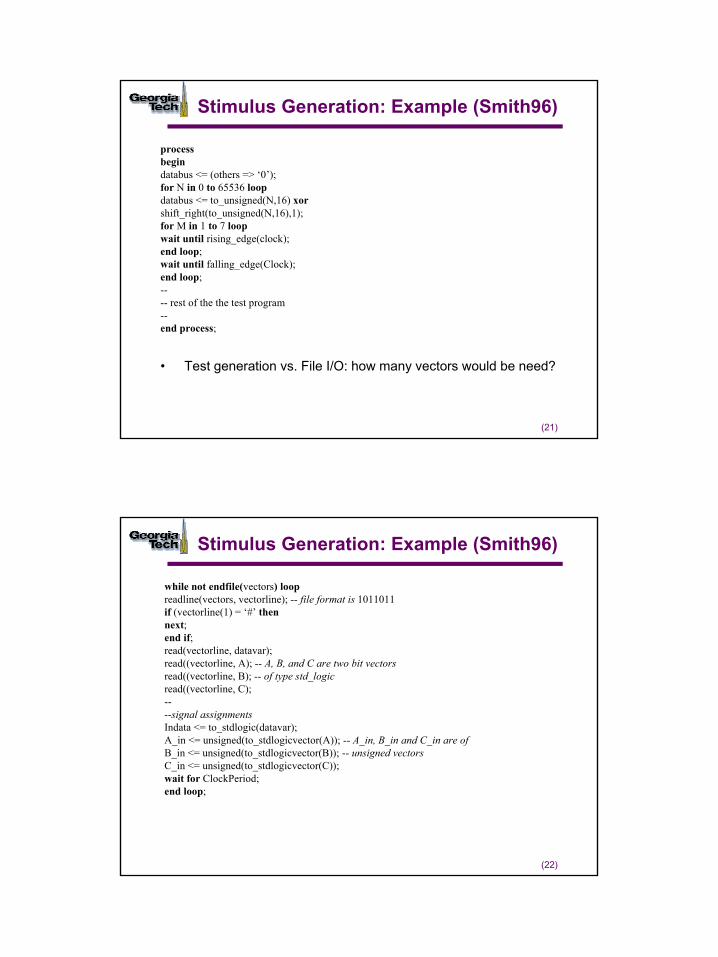
11
(21)
Stimulus Generation: Example (Smith96)
• Test generation vs. File I/O: how many vectors would be need?
processbegindatabus <= (others => ‘0’);for N in 0 to 65536 loopdatabus <= to_unsigned(N,16) xorshift_right(to_unsigned(N,16),1);for M in 1 to 7 loopwait until rising_edge(clock);end loop;wait until falling_edge(Clock);end loop;---- rest of the the test program--end process;
(22)
Stimulus Generation: Example (Smith96)
while not endfile(vectors) loopreadline(vectors, vectorline); -- file format is 1011011if (vectorline(1) = ‘#’ thennext;end if;read(vectorline, datavar);read((vectorline, A); -- A, B, and C are two bit vectorsread((vectorline, B); -- of type std_logicread((vectorline, C);----signal assignmentsIndata <= to_stdlogic(datavar);A_in <= unsigned(to_stdlogicvector(A)); -- A_in, B_in and C_in are ofB_in <= unsigned(to_stdlogicvector(B)); -- unsigned vectorsC_in <= unsigned(to_stdlogicvector(C));wait for ClockPeriod;end loop;
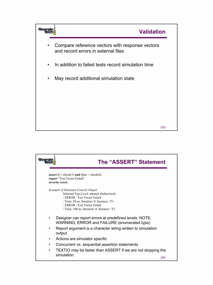
12
(23)
Validation
• Compare reference vectors with response vectors and record errors in external files
• In addition to failed tests record simulation time
• May record additional simulation state
(24)
The “ASSERT” Statement
• Designer can report errors at predefined levels: NOTE, WARNING, ERROR and FAILURE (enumerated type)
• Report argument is a character string written to simulation output
• Actions are simulator specific• Concurrent vs. sequential assertion statements• TEXTIO may be faster than ASSERT if we are not stopping the
simulation
assert Q = check(1) and Qbar = check(0)report “Test Vector Failed”severity error;
Example of Simulator Console OutputSelected Top-Level: srbench (behavioral): ERROR : Test Vector Failed: Time: 20 ns, Iteration: 0, Instance: /T1.: ERROR : Test Vector Failed: Time: 100 ns, Iteration: 0, Instance: /T1.
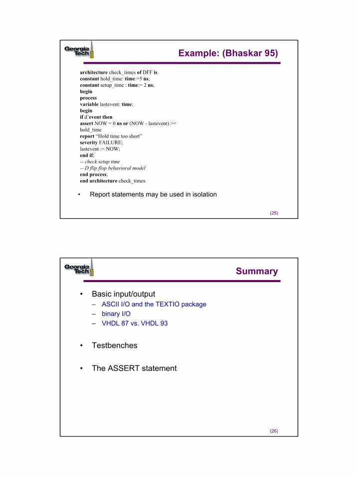
13
(25)
Example: (Bhaskar 95)
• Report statements may be used in isolation
architecture check_times of DFF isconstant hold_time: time:=5 ns;constant setup_time : time:= 2 ns;beginprocessvariable lastevent: time;beginif d’event thenassert NOW = 0 ns or (NOW - lastevent) >= hold_timereport “Hold time too short”severity FAILURE;lastevent := NOW;end if;-- check setup time-- D flip flop behavioral modelend process;end architecture check_times
(26)
Summary
• Basic input/output– ASCII I/O and the TEXTIO package– binary I/O– VHDL 87 vs. VHDL 93
• Testbenches
• The ASSERT statement
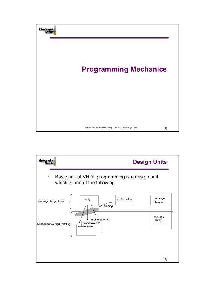
1
(1)
Programming Mechanics
© Sudhakar Yalamanchili, Georgia Institute of Technology, 2006
(2)
Design Units
• Basic unit of VHDL programming is a design unit which is one of the following
architecture-3architecture-2
architecture-1
entity configuration packageheader
package body
binding
Primary Design Units
Secondary Design Units
2
(3)
Name Spaces
• Multiple instances of a name can exist– Local names are the default– Provide the full path name for a name
• Visibility of names – Visibility of a name follows the hierarchy
• Declared in a package all design units that use the package• Entity in architectures used for this entity• Architecture processes used in the architecture• Process in the process• Subprogram subprogram
(4)
Compilation, Naming and Linking
• Design unit names are used to construct intermediate file names
• The libraries WORK and STD
DesignFile
VHDLAnalyzer
WORK STD IEEE
standard.vhd
std_logic_1164.vhdtextio.vhd
LibraryLibrary Library
full_adder.vhd
half_adder. vhd
.....
Sources and analyzed design units
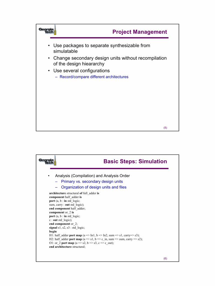
3
(5)
Project Management
• Use packages to separate synthesizable from simulatable
• Change secondary design units without recompilation of the design hieararchy
• Use several configurations– Record/compare different architectures
(6)
Basic Steps: Simulation
• Analysis (Compilation) and Analysis Order– Primary vs. secondary design units– Organization of design units and files
architecture structural of full_adder iscomponent half_adder isport (a, b : in std_logic;sum, carry : out std_logic);end component half_adder;component or_2 isport (a, b : in std_logic;c : out std_logic);end component or_2;signal s1, s2, s3 : std_logic;beginH1: half_adder port map (a => In1, b => In2, sum => s1, carry=> s3);H2: half_adder port map (a => s1, b => c_in, sum => sum, carry => s2);O1: or_2 port map (a => s2, b => s3, c => c_out);end architecture structural;
4
(7)
Compilation Dependencies
• Compilation dependencies follow hardware dependencies– Changes in the interface– Architecture changes can be insulated
• Note that recompilation is interpreted as a change– Locating architectures and entities in the same file– Creates dependencies that may not in fact exist
Micro3284
entity board isport (….
entity micro3284 isport (..
dependency
(8)
Basic Steps: Simulation
• Elaboration– Of the hierarchy produces a netlist of processes
– Of declarations• Generics and type checking
– Storage allocation– Initialization
s1
s2
s3
s4
s5
s6
z
5
(9)
Basic Steps: Simulation
• Initialization– All processes are executed until suspended by wait
statements or sensitivity lists– All nets initialized to default or user specified values– Initialize simulation time
• Simulation– Discrete event simulation– Two step model of time
• Set net values• Execute all affected processes and schedule new values for
nets– Simulator step time
1
(1)
Identifiers, Data Types, and Operators
© Sudhakar Yalamanchili, Georgia Institute of Technology, 2006
(2)
Identifiers, Data Types, and Operators
• Identifiers– Basic identifiers: start with a letter, do not end with “_”– Case insensitive
• Data Objects– Signals– Constants– Variables– Files
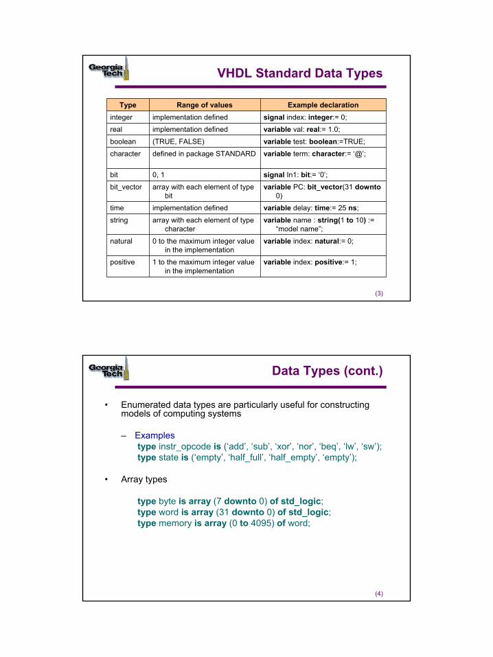
2
(3)
VHDL Standard Data Types
variable index: positive:= 1;1 to the maximum integer value in the implementation
positive
variable index: natural:= 0;0 to the maximum integer value in the implementation
natural
variable name : string(1 to 10) := “model name”;
array with each element of type character
string
variable delay: time:= 25 ns;implementation definedtime
variable PC: bit_vector(31 downto0)
array with each element of type bit
bit_vector
signal In1: bit:= ‘0’;0, 1bit
variable term: character:= ‘@’;defined in package STANDARDcharacter
variable test: boolean:=TRUE;(TRUE, FALSE)boolean
variable val: real:= 1.0;implementation definedreal signal index: integer:= 0;implementation definedinteger
Example declarationRange of valuesType
(4)
Data Types (cont.)
• Enumerated data types are particularly useful for constructing models of computing systems
– Examplestype instr_opcode is (‘add’, ‘sub’, ‘xor’, ‘nor’, ‘beq’, ‘lw’, ‘sw’);type state is (‘empty’, ‘half_full’, ‘half_empty’, ‘empty’);
• Array types
type byte is array (7 downto 0) of std_logic;type word is array (31 downto 0) of std_logic;type memory is array (0 to 4095) of word;
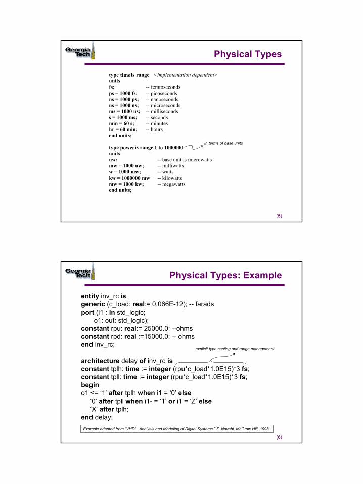
3
(5)
Physical Types
type time is range <implementation dependent>unitsfs; -- femtosecondsps = 1000 fs; -- picosecondsns = 1000 ps; -- nanosecondsus = 1000 ns; -- microsecondsms = 1000 us; -- millisecondss = 1000 ms; -- secondsmin = 60 s; -- minuteshr = 60 min; -- hoursend units;
type poweris range 1 to 1000000unitsuw; -- base unit is microwattsmw = 1000 uw; -- milliwattsw = 1000 mw; -- wattskw = 1000000 mw -- kilowattsmw = 1000 kw; -- megawattsend units;
In terms of base units
(6)
Physical Types: Example
entity inv_rc isgeneric (c_load: real:= 0.066E-12); -- faradsport (i1 : in std_logic;
o1: out: std_logic);constant rpu: real:= 25000.0; --ohmsconstant rpd: real :=15000.0; -- ohmsend inv_rc;
architecture delay of inv_rc isconstant tplh: time := integer (rpu*c_load*1.0E15)*3 fs;constant tpll: time := integer (rpu*c_load*1.0E15)*3 fs;begino1 <= ‘1’ after tplh when i1 = ‘0’ else
‘0’ after tpll when i1- = ‘1’ or i1 = ‘Z’ else‘X’ after tplh;
end delay;Example adapted from “VHDL: Analysis and Modeling of Digital Systems,” Z. Navabi, McGraw Hill, 1998.
explicit type casting and range management
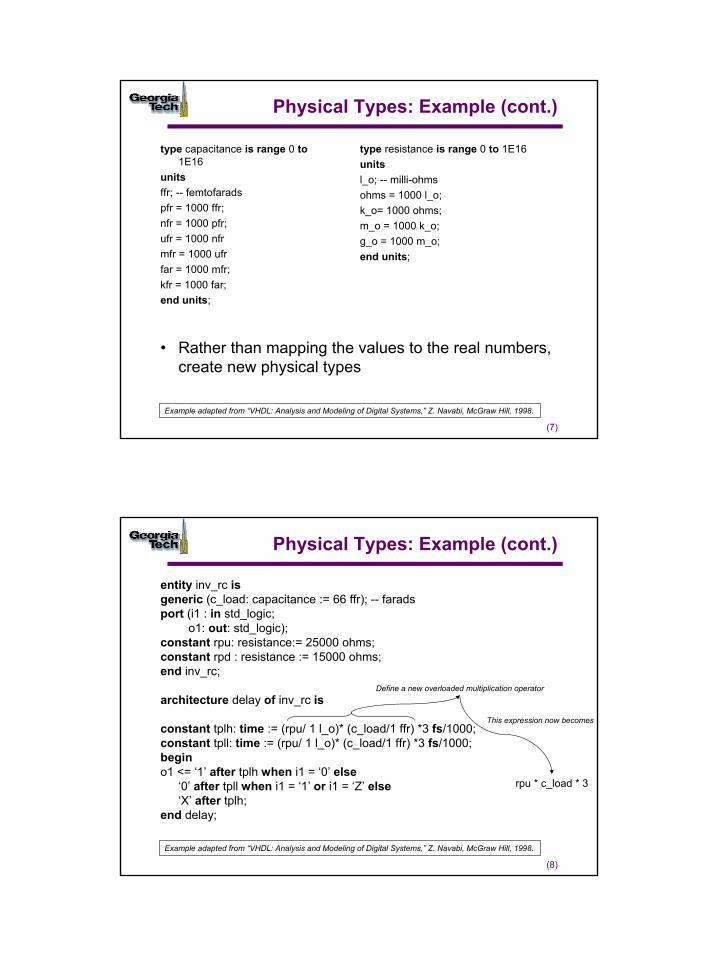
4
(7)
Physical Types: Example (cont.)
type capacitance is range 0 to1E16
unitsffr; -- femtofaradspfr = 1000 ffr;nfr = 1000 pfr;ufr = 1000 nfrmfr = 1000 ufrfar = 1000 mfr;kfr = 1000 far;end units;
type resistance is range 0 to 1E16unitsl_o; -- milli-ohmsohms = 1000 l_o;k_o= 1000 ohms;m_o = 1000 k_o;g_o = 1000 m_o;end units;
• Rather than mapping the values to the real numbers, create new physical types
Example adapted from “VHDL: Analysis and Modeling of Digital Systems,” Z. Navabi, McGraw Hill, 1998.
(8)
Physical Types: Example (cont.)
entity inv_rc isgeneric (c_load: capacitance := 66 ffr); -- faradsport (i1 : in std_logic;
o1: out: std_logic);constant rpu: resistance:= 25000 ohms;constant rpd : resistance := 15000 ohms;end inv_rc;
architecture delay of inv_rc is
constant tplh: time := (rpu/ 1 l_o)* (c_load/1 ffr) *3 fs/1000;constant tpll: time := (rpu/ 1 l_o)* (c_load/1 ffr) *3 fs/1000;begino1 <= ‘1’ after tplh when i1 = ‘0’ else
‘0’ after tpll when i1 = ‘1’ or i1 = ‘Z’ else‘X’ after tplh;
end delay;
Example adapted from “VHDL: Analysis and Modeling of Digital Systems,” Z. Navabi, McGraw Hill, 1998.
Define a new overloaded multiplication operator
rpu * c_load * 3
This expression now becomes
5
(9)
Modeling with Physical Types
• Use packages to encapsulate type definitions, type conversions functions and arithmetic functions for new types
• Examples– Modeling power– Modeling silicon area– Modeling physical resources that are “cumulative”
(10)
Operators
•VHDL ‘93 vs. VHDL ‘87 operators
¬abs **miscellaneous operators
remmod/*multiplying operators
–+ unary operators
&–+addition operatorsrorrolsraslasrlsllshift operators>=><=</==relational operators
xnorxor
nornand
orandlogical operators
• VHDL text or language reference manual for less commonly used operators and types


![Theory of latency-insensitive design - Computer-Aided ...luca/research/lipTransactions.pdf · delay-insensitive circuits [19], [20]. A delay-insensitive circuit is designed to operate](https://img.pdfslide.us/doc/110x75/5e77b28d15933b649935c2f3/theory-of-latency-insensitive-design-computer-aided-lucaresearchliptransactionspdf.jpg)