Embed Size (px)
Citation preview
ASICs...THE COURSE (1 WEEK)
1
VHDL
Key terms and concepts: syntax and semantics • identifiers (names) • entity and architecture •
package and library • interface (ports) • types • sequential statements • operators • arithmetic •
concurrent statements • execution • configuration and specification
History: U.S. Department of Defense (DoD) • VHDL (VHSIC hardware description language) •
VHSIC (very high-speed IC) program• Institute of Electrical and Electronics Engineers (IEEE) •
IEEE Standard 1076-1987 and 1076-1993 • MIL-STD-454 • Language Reference Manual
(LRM)
10.1 A Counter
Key terms and concepts: VHDL keywords • parallel programming language • VHDL is a
hardware description language • analysis (the VHDL word for “compiled”) • logic description,
simulation, and synthesis
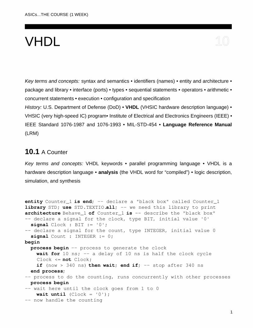
entity Counter_1 is end; -- declare a "black box" called Counter_1library STD; use STD.TEXTIO.all; -- we need this library to printarchitecture Behave_1 of Counter_1 is -- describe the "black box" -- declare a signal for the clock, type BIT, initial value '0' signal Clock : BIT := '0';-- declare a signal for the count, type INTEGER, initial value 0 signal Count : INTEGER := 0;begin process begin -- process to generate the clock wait for 10 ns; -- a delay of 10 ns is half the clock cycle Clock <= not Clock; if (now > 340 ns) then wait; end if; -- stop after 340 ns end process;-- process to do the counting, runs concurrently with other processes process begin -- wait here until the clock goes from 1 to 0 wait until (Clock = '0');-- now handle the counting
10
2 SECTION 10 VHDL ASICS... THE COURSE
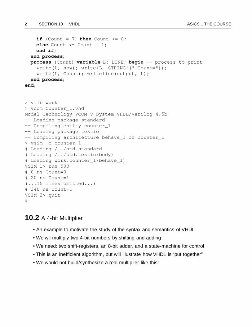
if (Count = 7) then Count <= 0; else Count <= Count + 1; end if; end process; process (Count) variable L: LINE; begin -- process to print write(L, now); write(L, STRING'(" Count=")); write(L, Count); writeline(output, L); end process;end;
> vlib work> vcom Counter_1.vhdModel Technology VCOM V-System VHDL/Verilog 4.5b-- Loading package standard-- Compiling entity counter_1-- Loading package textio-- Compiling architecture behave_1 of counter_1> vsim -c counter_1# Loading /../std.standard# Loading /../std.textio(body)# Loading work.counter_1(behave_1)VSIM 1> run 500# 0 ns Count=0# 20 ns Count=1(...15 lines omitted...)# 340 ns Count=1VSIM 2> quit>
10.2 A 4-bit Multiplier
• An example to motivate the study of the syntax and semantics of VHDL
• We wil multiply two 4-bit numbers by shifting and adding
• We need: two shift-registers, an 8-bit adder, and a state-machine for control
• This is an inefficient algorithm, but will illustrate how VHDL is “put together”
• We would not build/synthesize a real multiplier like this!
ASICs... THE COURSE 10.2 A 4-bit Multiplier 3
10.2.1 An 8-bit Adder
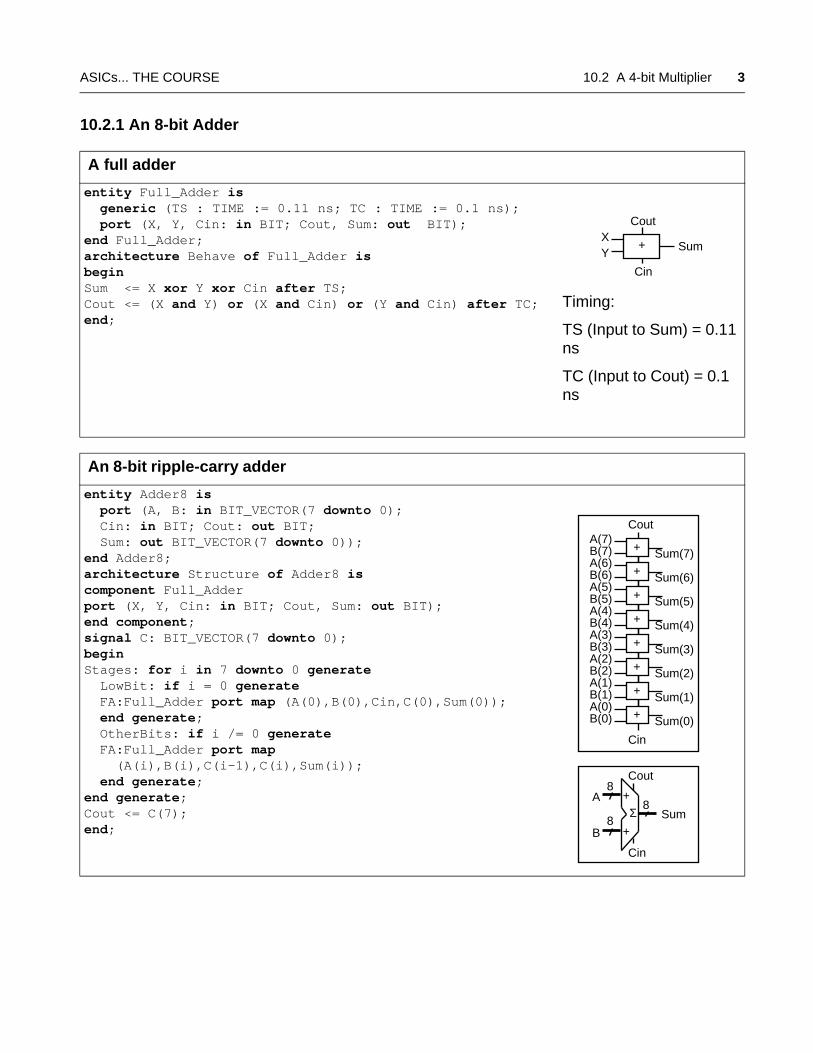
A full adder
entity Full_Adder is generic (TS : TIME := 0.11 ns; TC : TIME := 0.1 ns); port (X, Y, Cin: in BIT; Cout, Sum: out BIT);end Full_Adder;architecture Behave of Full_Adder isbegin Sum <= X xor Y xor Cin after TS;Cout <= (X and Y) or (X and Cin) or (Y and Cin) after TC;end;
Timing:
TS (Input to Sum) = 0.11 ns
TC (Input to Cout) = 0.1 ns
An 8-bit ripple-carry adder
entity Adder8 is port (A, B: in BIT_VECTOR(7 downto 0); Cin: in BIT; Cout: out BIT; Sum: out BIT_VECTOR(7 downto 0));end Adder8;architecture Structure of Adder8 iscomponent Full_Adderport (X, Y, Cin: in BIT; Cout, Sum: out BIT);end component;signal C: BIT_VECTOR(7 downto 0);begin Stages: for i in 7 downto 0 generate LowBit: if i = 0 generate FA:Full_Adder port map (A(0),B(0),Cin,C(0),Sum(0)); end generate; OtherBits: if i /= 0 generate FA:Full_Adder port map (A(i),B(i),C(i-1),C(i),Sum(i)); end generate;end generate;Cout <= C(7);end;
Cin
Cout
SumXY
+
Sum(7)A(7)B(7)
Sum(6)A(6)B(6)
Sum(5)A(5)B(5)
Sum(4)A(4)B(4)
Sum(3)A(3)B(3)
Sum(2)A(2)B(2)
Sum(1)A(1)B(1)
Sum(0)A(0)B(0)
Cout
Cin
SumA
B
Cin
Cout8
8Σ
+
+
8
+
+
+
+
+
+
+
+
4 SECTION 10 VHDL ASICS... THE COURSE
10.2.2 A Register Accumulator
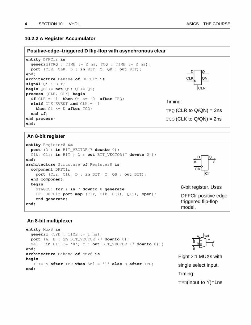
Positive-edge–triggered D flip-flop with asynchronous clear
entity DFFClr is generic(TRQ : TIME := 2 ns; TCQ : TIME := 2 ns); port (CLR, CLK, D : in BIT; Q, QB : out BIT); end;architecture Behave of DFFClr issignal Qi : BIT;begin QB <= not Qi; Q <= Qi;process (CLR, CLK) begin if CLR = '1' then Qi <= '0' after TRQ; elsif CLK'EVENT and CLK = '1' then Qi <= D after TCQ; end if;end process;end;
Timing:
TRQ (CLR to Q/QN) = 2ns
TCQ (CLK to Q/QN) = 2ns
An 8-bit register
entity Register8 is port (D : in BIT_VECTOR(7 downto 0); Clk, Clr: in BIT ; Q : out BIT_VECTOR(7 downto 0));end;architecture Structure of Register8 is component DFFClr port (Clr, Clk, D : in BIT; Q, QB : out BIT); end component; begin STAGES: for i in 7 downto 0 generate FF: DFFClr port map (Clr, Clk, D(i), Q(i), open); end generate;end;
8-bit register. Uses
DFFClr positive edge-triggered flip-flop model.
An 8-bit multiplexer
entity Mux8 is generic (TPD : TIME := 1 ns); port (A, B : in BIT_VECTOR (7 downto 0); Sel : in BIT := '0'; Y : out BIT_VECTOR (7 downto 0));end;architecture Behave of Mux8 isbegin Y <= A after TPD when Sel = '1' else B after TPD;end;
Eight 2:1 MUXs with
single select input.
Timing:
TPD(input to Y)=1ns
D Q
QNCLK
CLR
D Q
ClkClr
88
88
Sel
01
A
BY
8
ASICs... THE COURSE 10.2 A 4-bit Multiplier 5
10.2.3 Zero Detector
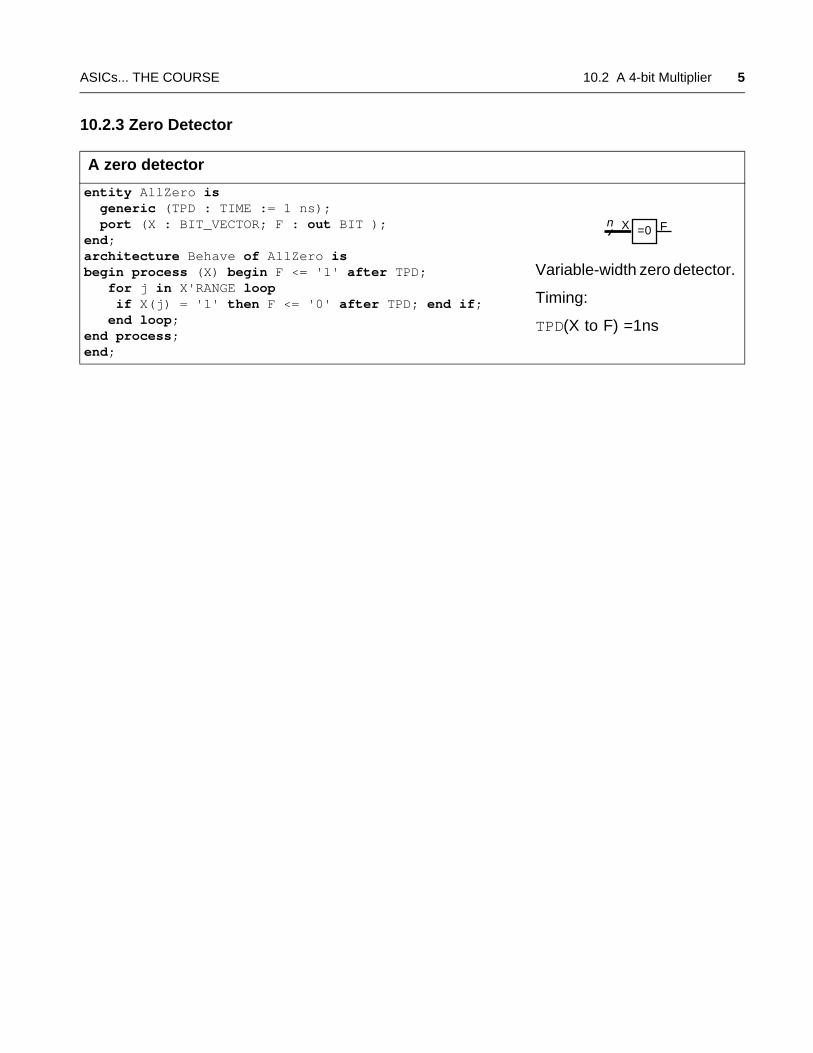
A zero detector
entity AllZero is generic (TPD : TIME := 1 ns); port (X : BIT_VECTOR; F : out BIT );end;architecture Behave of AllZero isbegin process (X) begin F <= '1' after TPD; for j in X'RANGE loop if X(j) = '1' then F <= '0' after TPD; end if; end loop;end process;end;
Variable-width zero detector.
Timing:
TPD(X to F) =1ns
=0X Fn
6 SECTION 10 VHDL ASICS... THE COURSE
10.2.4 A Shift Register
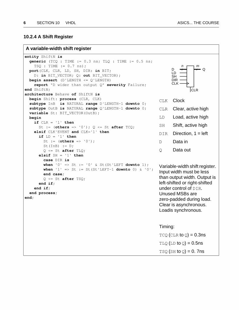
A variable-width shift register
entity ShiftN is generic (TCQ : TIME := 0.3 ns; TLQ : TIME := 0.5 ns; TSQ : TIME := 0.7 ns); port(CLK, CLR, LD, SH, DIR: in BIT; D: in BIT_VECTOR; Q: out BIT_VECTOR); begin assert (D'LENGTH <= Q'LENGTH) report "D wider than output Q" severity Failure;end ShiftN;architecture Behave of ShiftN is begin Shift: process (CLR, CLK) subtype InB is NATURAL range D'LENGTH-1 downto 0; subtype OutB is NATURAL range Q'LENGTH-1 downto 0; variable St: BIT_VECTOR(OutB); begin if CLR = '1' then St := (others => '0'); Q <= St after TCQ; elsif CLK'EVENT and CLK='1' then if LD = '1' then St := (others => '0'); St(InB) := D; Q <= St after TLQ; elsif SH = '1' then case DIR is when '0' => St := '0' & St(St'LEFT downto 1); when '1' => St := St(St'LEFT-1 downto 0) & '0'; end case; Q <= St after TSQ; end if; end if; end process;end;
CLK Clock
CLR Clear, active high
LD Load, active high
SH Shift, active high
DIR Direction, 1 = left
D Data in
Q Data out
Variable-width shift register.Input width must be lessthan output width. Output isleft-shifted or right-shiftedunder control of DIR. Unused MSBs are zero-padded during load.Clear is asynchronous. Loadis synchronous.
Timing:
TCQ (CLR to Q) = 0.3ns
TLQ (LD to Q) = 0.5ns
TSQ (SH to Q) = 0. 7ns
D Q
CLKDIR
LD
CLR
SH
n m
ASICs... THE COURSE 10.2 A 4-bit Multiplier 7
10.2.5 A State Machine
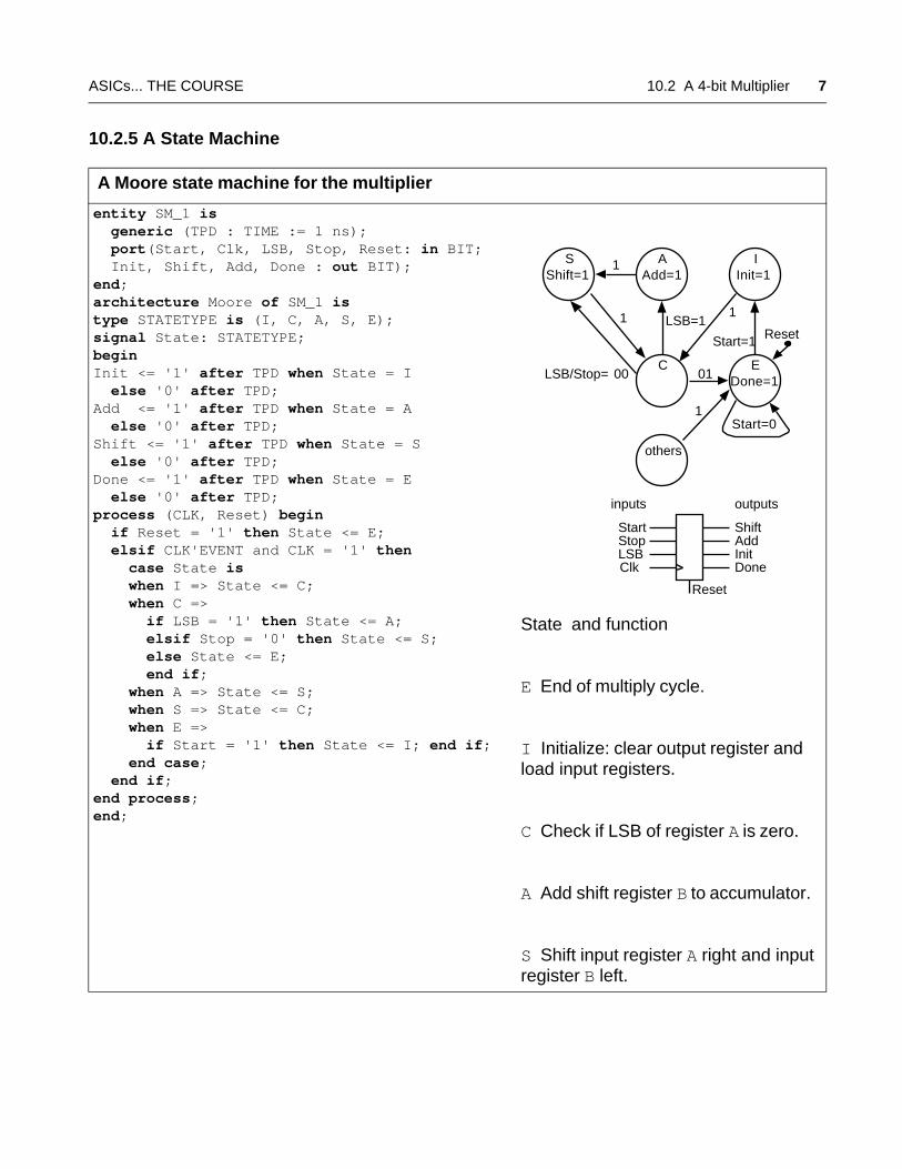
A Moore state machine for the multiplier
entity SM_1 is generic (TPD : TIME := 1 ns); port(Start, Clk, LSB, Stop, Reset: in BIT; Init, Shift, Add, Done : out BIT);end;architecture Moore of SM_1 istype STATETYPE is (I, C, A, S, E);signal State: STATETYPE;begin Init <= '1' after TPD when State = I else '0' after TPD;Add <= '1' after TPD when State = A else '0' after TPD;Shift <= '1' after TPD when State = S else '0' after TPD;Done <= '1' after TPD when State = E else '0' after TPD;process (CLK, Reset) begin if Reset = '1' then State <= E; elsif CLK'EVENT and CLK = '1' then case State is when I => State <= C; when C => if LSB = '1' then State <= A; elsif Stop = '0' then State <= S; else State <= E; end if; when A => State <= S; when S => State <= C; when E => if Start = '1' then State <= I; end if; end case; end if;end process;end;
State and function
E End of multiply cycle.
I Initialize: clear output register andload input registers.
C Check if LSB of register A is zero.
A Add shift register B to accumulator.
S Shift input register A right and inputregister B left.
C
SShift=1
AAdd=1
IInit=1
E01 Done=1
Start=1
LSB=1
LSB/Stop= 00
Start=0
others
Start Shift
DoneClk
AddInitLSB
Stop
11
1
1
inputs outputs
Reset
Reset
8 SECTION 10 VHDL ASICS... THE COURSE
10.2.6 A Multiplier
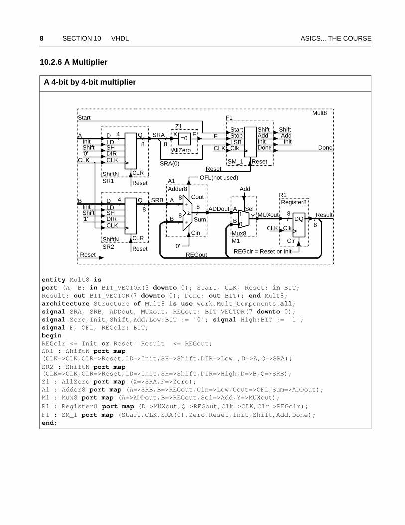
A 4-bit by 4-bit multiplier
entity Mult8 isport (A, B: in BIT_VECTOR(3 downto 0); Start, CLK, Reset: in BIT;Result: out BIT_VECTOR(7 downto 0); Done: out BIT); end Mult8;architecture Structure of Mult8 is use work.Mult_Components.all;signal SRA, SRB, ADDout, MUXout, REGout: BIT_VECTOR(7 downto 0);signal Zero,Init,Shift,Add,Low:BIT := '0'; signal High:BIT := '1';signal F, OFL, REGclr: BIT; begin REGclr <= Init or Reset; Result <= REGout;SR1 : ShiftN port map (CLK=>CLK,CLR=>Reset,LD=>Init,SH=>Shift,DIR=>Low ,D=>A,Q=>SRA);SR2 : ShiftN port map (CLK=>CLK,CLR=>Reset,LD=>Init,SH=>Shift,DIR=>High,D=>B,Q=>SRB);Z1 : AllZero port map (X=>SRA,F=>Zero);A1 : Adder8 port map (A=>SRB,B=>REGout,Cin=>Low,Cout=>OFL,Sum=>ADDout);M1 : Mux8 port map (A=>ADDout,B=>REGout,Sel=>Add,Y=>MUXout);
R1 : Register8 port map (D=>MUXout,Q=>REGout,Clk=>CLK,Clr=>REGclr);F1 : SM_1 port map (Start,CLK,SRA(0),Zero,Reset,Init,Shift,Add,Done);end;
D Q
CLKDIR
LD
CLR
SH
D Q
CLKDIR
LD
CLR
SHSum
A
B
Cin
Cout
8 Σ+
+
8
A
B
CLK
SR1
SR2
SRA
SRB
DQ
Clk
Clr
8
8
SRA(0)
Start Shift
DoneClk
AddInitLSB
Stop
REGout
R1
A1
F1
CLK
Mult8
Result
84
4
'0'
OFL(not used)
8
8
Start
CLK'0'
'1'
Shift
Shift
Init
Init
REGclr = Reset or Init
Sel
0
1A
BY
M1
Z1
Done
ResetReset
Reset
ADDout
AddReset
Reset
8
MUXout
FX FShiftAddInit
SM_1
AllZero
Register8
Mux8
Adder8
ShiftN
ShiftN
=0
ASICs... THE COURSE 10.2 A 4-bit Multiplier 9
10.2.7 Packages and Testbench
package Mult_Components is --1component Mux8 port (A,B:BIT_VECTOR(7 downto 0); --2 Sel:BIT;Y:out BIT_VECTOR(7 downto 0));end component; --3component AllZero port (X : BIT_VECTOR; --4 F:out BIT );end component; --5component Adder8 port (A,B:BIT_VECTOR(7 downto 0);Cin:BIT; --6 Cout:out BIT;Sum:out BIT_VECTOR(7 downto 0));end component; --7component Register8 port (D:BIT_VECTOR(7 downto 0); --8 Clk,Clr:BIT; Q:out BIT_VECTOR(7 downto 0));end component; --9component ShiftN port (CLK,CLR,LD,SH,DIR:BIT;D:BIT_VECTOR; --10 Q:out BIT_VECTOR);end component; --11component SM_1 port (Start,CLK,LSB,Stop,Reset:BIT; --12 Init,Shift,Add,Done:out BIT);end component; --13end; --14
Utility code to help test the multiplier:
package Clock_Utils is --1procedure Clock (signal C: out Bit; HT, LT:TIME); --2end Clock_Utils; --3
package body Clock_Utils is --4procedure Clock (signal C: out Bit; HT, LT:TIME) is --5begin --6 loop C<='1' after LT, '0' after LT + HT; wait for LT + HT; --7 end loop; --8end; --9end Clock_Utils; --10
Two functions for testing—to convert an array of bits to a number and vice versa:
package Utils is --1 function Convert (N,L: NATURAL) return BIT_VECTOR; --2 function Convert (B: BIT_VECTOR) return NATURAL; --3end Utils; --4
package body Utils is --5 function Convert (N,L: NATURAL) return BIT_VECTOR is --6 variable T:BIT_VECTOR(L-1 downto 0); --7 variable V:NATURAL:= N; --8 begin for i in T'RIGHT to T'LEFT loop --9 T(i) := BIT'VAL(V mod 2); V:= V/2; --10 end loop; return T; --11 end; --12 function Convert (B: BIT_VECTOR) return NATURAL is --13 variable T:BIT_VECTOR(B'LENGTH-1 downto 0) := B; --14
10 SECTION 10 VHDL ASICS... THE COURSE
variable V:NATURAL:= 0; --15 begin for i in T'RIGHT to T'LEFT loop --16 if T(i) = '1' then V:= V + (2**i); end if; --17 end loop; return V; --18 end; --19end Utils; --20
The following testbench exercises the multiplier model:
entity Test_Mult8_1 is end; -- runs forever, use break!! --1architecture Structure of Test_Mult8_1 is --2use Work.Utils.all; use Work.Clock_Utils.all; --3 component Mult8 port --4 (A, B : BIT_VECTOR(3 downto 0); Start, CLK, Reset : BIT; --5 Result : out BIT_VECTOR(7 downto 0); Done : out BIT); --6 end component; --7signal A, B : BIT_VECTOR(3 downto 0); --8signal Start, Done : BIT := '0'; --9signal CLK, Reset : BIT; --10signal Result : BIT_VECTOR(7 downto 0); --11signal DA, DB, DR : INTEGER range 0 to 255; --12begin --13C: Clock(CLK, 10 ns, 10 ns); --14UUT: Mult8 port map (A, B, Start, CLK, Reset, Result, Done); --15DR <= Convert(Result); --16Reset <= '1', '0' after 1 ns; --17process begin --18 for i in 1 to 3 loop for j in 4 to 7 loop --19 DA <= i; DB <= j; --20 A<=Convert(i,A'Length);B<=Convert(j,B'Length); --21 wait until CLK'EVENT and CLK='1'; wait for 1 ns; --22 Start <= '1', '0' after 20 ns; wait until Done = '1'; --23 wait until CLK'EVENT and CLK='1'; --24 end loop; end loop; --25 for i in 0 to 1 loop for j in 0 to 15 loop --26 DA <= i; DB <= j; --27 A<=Convert(i,A'Length);B<=Convert(j,B'Length); --28 wait until CLK'EVENT and CLK='1'; wait for 1 ns; --29 Start <= '1', '0' after 20 ns; wait until Done = '1'; --30 wait until CLK'EVENT and CLK='1'; --31 end loop; end loop; --32 wait; --33end process; --34end; --35
ASICs... THE COURSE 10.3 Syntax and Semanticsof VHDL 11
10.3 Syntax and Semanticsof VHDL
Key terms: syntax rules• Backus–Naur form (BNF) • constructs • semantic rules • lexical rules
sentence ::= subject verb object.subject ::= The|A noun object ::= [article] noun {, and article noun}article ::= the|anoun ::= man|shark|house|foodverb ::= eats|paints
::= means "can be replaced by" | means "or" [] means "contents optional"{} means "contents can be left out, used once, or repeated"
The following two sentences are correct according to the syntax rules:
A shark eats food.The house paints the shark, and the house, and a man.
Semantic rules tell us that the second sentence does not make much sense.
12 SECTION 10 VHDL ASICS... THE COURSE
10.4 Identifiers and Literals
Key terms: nouns of VHDL • identifiers • literals • VHDL is not case sensitive • static (known at
analysis) • abstract literals (decimal or based) • decimal literals (integer or real) • character
literals • bit-string literals
identifier ::= letter {[underline] letter_or_digit} |\graphic_character{graphic_character}\
s -- A simple name.S -- A simple name, the same as s. VHDL is not case sensitive.a_name -- Imbedded underscores are OK.-- Successive underscores are illegal in names: Ill__egal-- Names can't start with underscore: _Illegal-- Names can't end with underscore: Illegal_Too_Good -- Names must start with a letter.-- Names can't start with a number: 2_Bad \74LS00\ -- Extended identifier to break rules (VHDL-93 only).VHDL \vhdl\ \VHDL\ -- Three different names (VHDL-93 only).s_array(0) -- A static indexed name (known at analysis time).s_array(i) -- A non-static indexed name, if i is a variable.
entity Literals_1 is end;architecture Behave of Literals_1 isbegin process variable I1 : integer; variable Rl : real; variable C1 : CHARACTER; variable S16 : STRING(1 to 16); variable BV4: BIT_VECTOR(0 to 3); variable BV12 : BIT_VECTOR(0 to 11); variable BV16 : BIT_VECTOR(0 to 15); begin-- Abstract literals are decimal or based literals.-- Decimal literals are integer or real literals.-- Integer literal examples (each of these is the same): I1 := 120000; Int := 12e4; Int := 120_000; -- Based literal examples (each of these is the same): I1 := 2#1111_1111#; I1 := 16#FFFF#; -- Base must be an integer from 2 to 16: I1 := 16:FFFF:; -- you may use a : if you don't have #
ASICs... THE COURSE 10.5 Entities and Architectures 13
-- Real literal examples (each of these is the same): Rl := 120000.0; Rl := 1.2e5; Rl := 12.0E4; -- Character literal must be one of the 191 graphic characters.-- 65 of the 256 ISO Latin-1 set are non-printing control characters C1 := 'A'; C1 := 'a'; -- different from each other-- String literal examples: S16 := " string" & " literal"; -- concatenate long strings S16 := """Hello,"" I said!"; -- doubled quotes S16 := % string literal%; -- can use % instead of " S16 := %Sale: 50%% off!!!%; -- doubled %-- Bit-string literal examples: BV4 := B"1100"; -- binary bit-string literal BV12 := O"7777"; -- octal bit-string literal BV16 := X"FFFF"; -- hex bit-string literalwait; end process; -- the wait prevents an endless loopend;
10.5 Entities and Architectures
Key terms: design file (bookshelf) • design units • library units (book) • library (collection of
bookshelves) • primary units • secondary units (c.f. Table of Contents) • entity declaration
(black box) • formal ports ( or formals) • architecture body (contents of black box) • visibility •
component declaration • structural model • local ports (or locals) • instance names • actual ports
(or actuals) • binding • configuration declaration (a “shopping list”) • design entity
(entity–architecture pair)
design_file ::= {library_clause|use_clause} library_unit {{library_clause|use_clause} library_unit}
library_unit ::= primary_unit|secondary_unit
primary_unit ::= entity_declaration|configuration_declaration|package_declaration
secondary_unit ::= architecture_body|package_body
14 SECTION 10 VHDL ASICS... THE COURSE
entity_declaration ::= entity identifier is [generic (formal_generic_interface_list);] [port (formal_port_interface_list);] {entity_declarative_item} [begin {[label:] [postponed] assertion ; |[label:] [postponed] passive_procedure_call ; |passive_process_statement}]end [entity] [entity_identifier] ;
entity Half_Adder is port (X, Y : in BIT := '0'; Sum, Cout : out BIT); -- formalsend;
architecture_body ::= architecture identifier of entity_name is {block_declarative_item} begin {concurrent_statement} end [architecture] [architecture_identifier] ;
architecture Behave of Half_Adder is begin Sum <= X xor Y; Cout <= X and Y;end Behave;
Components:
component_declaration ::= component identifier [is] [generic (local_generic_interface_list);] [port (local_port_interface_list);] end component [component_identifier];
architecture Netlist of Half_Adder iscomponent MyXor port (A_Xor,B_Xor : in BIT; Z_Xor : out BIT);end component; -- component with localscomponent MyAnd port (A_And,B_And : in BIT; Z_And : out BIT);end component; -- component with locals
ASICs... THE COURSE 10.5 Entities and Architectures 15
begin Xor1: MyXor port map (X, Y, Sum); -- instance with actuals And1 : MyAnd port map (X, Y, Cout); -- instance with actualsend;
These design entities (entity–architecture pairs) would be part of a technology library:
entity AndGate is port (And_in_1, And_in_2 : in BIT; And_out : out BIT); -- formalsend;
architecture Simple of AndGate is begin And_out <= And_in_1 and And_in_2;end;
entity XorGate is port (Xor_in_1, Xor_in_2 : in BIT; Xor_out : out BIT); -- formalsend;
architecture Simple of XorGate is begin Xor_out <= Xor_in_1 xor Xor_in_2;end;
configuration_declaration ::= configuration identifier of entity_name is {use_clause|attribute_specification|group_declaration} block_configuration end [configuration] [configuration_identifier] ;
configuration Simplest of Half_Adder isuse work.all; for Netlist for And1 : MyAnd use entity AndGate(Simple) port map -- association: formals => locals (And_in_1 => A_And, And_in_2 => B_And, And_out => Z_And); end for; for Xor1 : MyXor use entity XorGate(Simple) port map (Xor_in_1 => A_Xor, Xor_in_2 => B_Xor, Xor_out => Z_Xor);
16 SECTION 10 VHDL ASICS... THE COURSE
end for; end for;end;
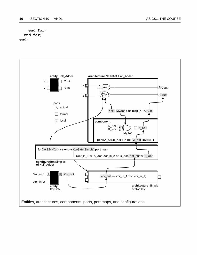
Entities, architectures, components, ports, port maps, and configurations
architecture Netlist of Half_Adder
Xor_outXor_in_1
entityXorGate
Xor_in_2
F
F
F
Cout
Sum
X
Y
entity Half_Adder
And1
Xor1
X
Y
Cout
SumA
A A
A
for Xor1:MyXor use entity XorGate(Simple) port map
component
(Xor_in_1 => A_Xor, Xor_in_2 => B_Xor, Xor_out => Z_Xor);
configuration Simplestof Half_Adder
Xor1: MyXor port map (X, Y, Sum);
port (A_Xor,B_Xor : in BIT; Z_Xor : out BIT)
A_XorB_Xor Z_Xor
MyXor
LLL
Xor_out <= Xor_in_1 xor Xor_in_2;
architecture Simpleof XorGate
A actual
F formal
L local
ports
ASICs... THE COURSE 10.6 Packages and Libraries 17
10.6 Packages and Libraries
Key terms: design library (the current working library or a resource library) • working library
(work) • package • package body • package visibility • library clause • use clause
package_declaration ::= package identifier is{subprogram_declaration | type_declaration | subtype_declaration | constant_declaration | signal_declaration | file_declaration | alias_declaration | component_declaration | attribute_declaration | attribute_specification | disconnection_specification | use_clause | shared_variable_declaration | group_declaration | group_template_declaration} end [package] [package_identifier] ;
package_body ::= package body package_identifier is{subprogram_declaration | subprogram_body | type_declaration | subtype_declaration | constant_declaration | file_declaration | alias_declaration | use_clause | shared_variable_declaration | group_declaration | group_template_declaration} end [package body] [package_identifier] ;
library MyLib; -- library clauseuse MyLib.MyPackage.all; -- use clause-- design unit (entity + architecture, etc.) follows:
10.6.1 Standard Package
Key terms: STANDARD package (defined in the LRM ) • TIME • INTEGER • REAL • STRING •
CHARACTER • I use uppercase for standard types • ISO 646-1983 • ASCII character set •
character codes • graphic symbol (glyph) • ISO 8859-1:1987(E) • ISO Latin-1
package Part_STANDARD istype BOOLEAN is (FALSE, TRUE); type BIT is ('0', '1');
18 SECTION 10 VHDL ASICS... THE COURSE
type SEVERITY_LEVEL is (NOTE, WARNING, ERROR, FAILURE);subtype NATURAL is INTEGER range 0 to INTEGER'HIGH;subtype POSITIVE is INTEGER range 1 to INTEGER'HIGH;type BIT_VECTOR is array (NATURAL range <>) of BIT;type STRING is array (POSITIVE range <>) of CHARACTER;-- the following declarations are VHDL-93 only:attribute FOREIGN: STRING; -- for links to other languagessubtype DELAY_LENGTH is TIME range 0 fs to TIME'HIGH;type FILE_OPEN_KIND is (READ_MODE,WRITE_MODE,APPEND_MODE);type FILE_OPEN_STATUS is(OPEN_OK,STATUS_ERROR,NAME_ERROR,MODE_ERROR);end Part_STANDARD;
type TIME is range implementation_defined -- and varies with software units fs; ps = 1000 fs; ns = 1000 ps; us = 1000 ns; ms = 1000 us; sec = 1000 ms; min = 60 sec; hr = 60 min; end units;
type Part_CHARACTER is ( -- 128 ASCII characters in VHDL-87 NUL, SOH, STX, ETX, EOT, ENQ, ACK, BEL, -- 33 control characters BS, HT, LF, VT, FF, CR, SO, SI, -- including:DLE, DC1, DC2, DC3, DC4, NAK, SYN, ETB, -- format effectors:CAN, EM, SUB, ESC, FSP, GSP, RSP, USP, -- horizontal tab = HT' ', '!', '"', '#', '$', '%', '&', ''', -- line feed = LF'(', ')', '*', '+', ',', '-', '.', '/', -- vertical tab = VT'0', '1', '2', '3', '4', '5', '6', '7', -- form feed = FF'8', '9', ':', ';', '<', '=', '>', '?', -- carriage return = CR'@', 'A', 'B', 'C', 'D', 'E', 'F', 'G', -- and others:'H', 'I', 'J', 'K', 'L', 'M', 'N', 'O', -- FSP, GSP, RSP, USP use P'P', 'Q', 'R', 'S', 'T', 'U', 'V', 'W', -- suffix to avoid conflict'X', 'Y', 'Z', '[', '\', ']', '^', '_', -- with TIME units'`', 'a', 'b', 'c', 'd', 'e', 'f', 'g', 'h', 'i', 'j', 'k', 'l', 'm', 'n', 'o', 'p', 'q', 'r', 's', 't', 'u', 'v', 'w', 'x', 'y', 'z', '{', '|', '}', '~', DEL -- delete = DEL
-- VHDL-93 includes 96 more Latin-1 characters, like ¥ (Yen) and -- 32 more control characters, better not to use any of them.);
ASICs... THE COURSE 10.6 Packages and Libraries 19
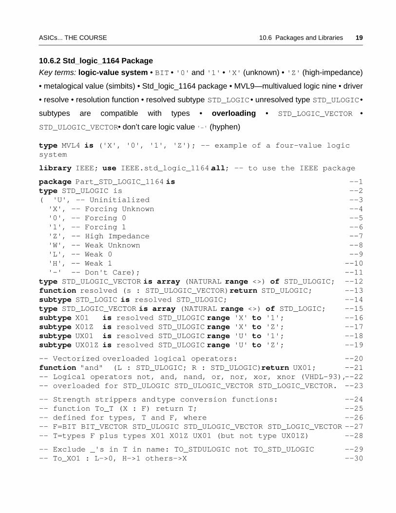
10.6.2 Std_logic_1164 Package
Key terms: logic-value system • BIT • '0' and '1' • 'X' (unknown) • 'Z' (high-impedance)
• metalogical value (simbits) • Std_logic_1164 package • MVL9—multivalued logic nine • driver
• resolve • resolution function • resolved subtype STD_LOGIC • unresolved type STD_ULOGIC •
subtypes are compatible with types • overloading • STD_LOGIC_VECTOR •
STD_ULOGIC_VECTOR • don’t care logic value '-' (hyphen)
type MVL4 is ('X', '0', '1', 'Z'); -- example of a four-value logic system
library IEEE; use IEEE.std_logic_1164.all; -- to use the IEEE package
package Part_STD_LOGIC_1164 is --1type STD_ULOGIC is --2( 'U', -- Uninitialized --3 'X', -- Forcing Unknown --4 '0', -- Forcing 0 --5 '1', -- Forcing 1 --6 'Z', -- High Impedance --7 'W', -- Weak Unknown --8 'L', -- Weak 0 --9 'H', -- Weak 1 --10 '-' -- Don't Care); --11type STD_ULOGIC_VECTOR is array (NATURAL range <>) of STD_ULOGIC; --12function resolved (s : STD_ULOGIC_VECTOR) return STD_ULOGIC; --13subtype STD_LOGIC is resolved STD_ULOGIC; --14type STD_LOGIC_VECTOR is array (NATURAL range <>) of STD_LOGIC; --15subtype X01 is resolved STD_ULOGIC range 'X' to '1'; --16subtype X01Z is resolved STD_ULOGIC range 'X' to 'Z'; --17subtype UX01 is resolved STD_ULOGIC range 'U' to '1'; --18subtype UX01Z is resolved STD_ULOGIC range 'U' to 'Z'; --19
-- Vectorized overloaded logical operators: --20function "and" (L : STD_ULOGIC; R : STD_ULOGIC) return UX01; --21-- Logical operators not, and, nand, or, nor, xor, xnor (VHDL-93),--22-- overloaded for STD_ULOGIC STD_ULOGIC_VECTOR STD_LOGIC_VECTOR. --23
-- Strength strippers and type conversion functions: --24-- function To_T (X : F) return T; --25-- defined for types, T and F, where --26-- F=BIT BIT_VECTOR STD_ULOGIC STD_ULOGIC_VECTOR STD_LOGIC_VECTOR --27-- T=types F plus types X01 X01Z UX01 (but not type UX01Z) --28
-- Exclude _'s in T in name: TO_STDULOGIC not TO_STD_ULOGIC --29-- To_XO1 : L->0, H->1 others->X --30
20 SECTION 10 VHDL ASICS... THE COURSE
-- To_XO1Z: Z->Z, others as To_X01 --31-- To_UX01: U->U, others as To_X01 --32
-- Edge detection functions: --33function rising_edge (signal s: STD_ULOGIC) return BOOLEAN; --34function falling_edge (signal s: STD_ULOGIC) return BOOLEAN; --35
-- Unknown detection (returns true if s = U, X, Z, W): --36-- function Is_X (s : T) return BOOLEAN; --37-- defined for T = STD_ULOGIC STD_ULOGIC_VECTOR STD_LOGIC_VECTOR. --38
end Part_STD_LOGIC_1164; --39
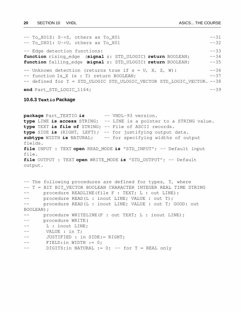
10.6.3 Textio Package
package Part_TEXTIO is -- VHDL-93 version.type LINE is access STRING; -- LINE is a pointer to a STRING value.type TEXT is file of STRING; -- File of ASCII records. type SIDE is (RIGHT, LEFT); -- for justifying output data. subtype WIDTH is NATURAL; -- for specifying widths of output fields. file INPUT : TEXT open READ_MODE is "STD_INPUT"; -- Default input file.file OUTPUT : TEXT open WRITE_MODE is "STD_OUTPUT"; -- Default output.
-- The following procedures are defined for types, T, where -- T = BIT BIT_VECTOR BOOLEAN CHARACTER INTEGER REAL TIME STRING-- procedure READLINE(file F : TEXT; L : out LINE);-- procedure READ(L : inout LINE; VALUE : out T);-- procedure READ(L : inout LINE; VALUE : out T; GOOD: out BOOLEAN);-- procedure WRITELINE(F : out TEXT; L : inout LINE);-- procedure WRITE(-- L : inout LINE; -- VALUE : in T; -- JUSTIFIED : in SIDE:= RIGHT; -- FIELD:in WIDTH := 0; -- DIGITS:in NATURAL := 0; -- for T = REAL only
ASICs... THE COURSE 10.6 Packages and Libraries 21
-- UNIT:in TIME:= ns); -- for T = TIME only-- function ENDFILE(F : in TEXT) return BOOLEAN;
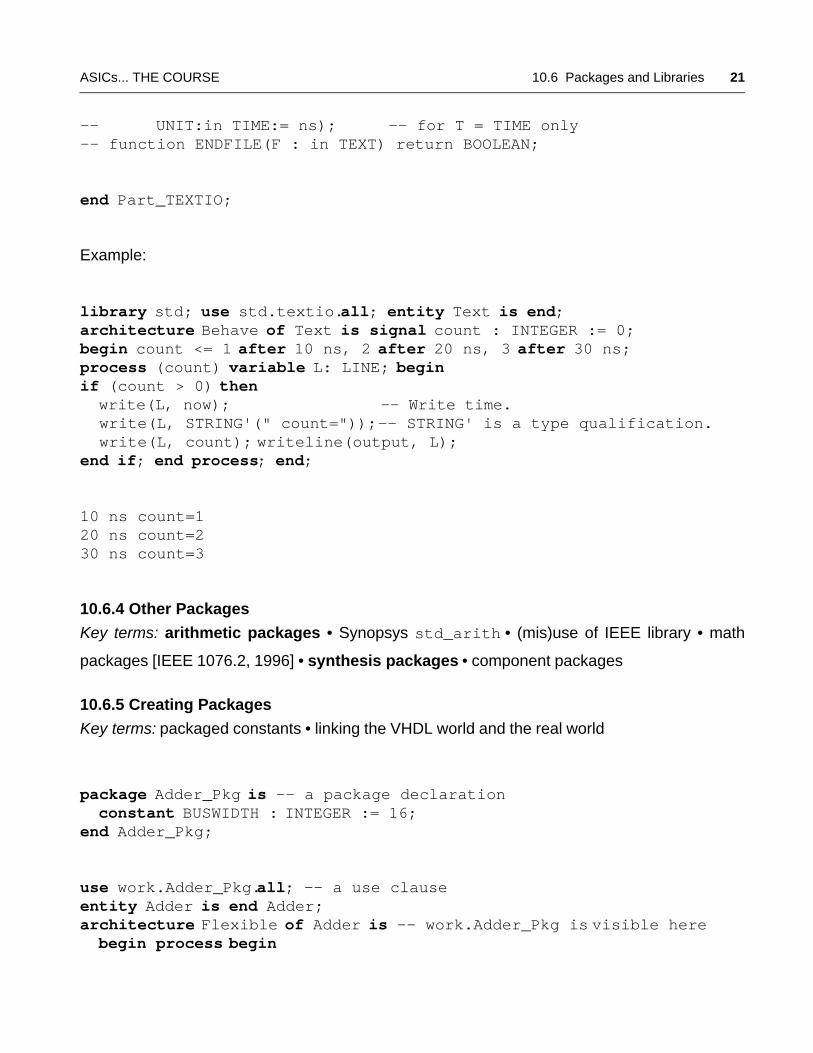
end Part_TEXTIO;
Example:
library std; use std.textio.all; entity Text is end;architecture Behave of Text is signal count : INTEGER := 0;begin count <= 1 after 10 ns, 2 after 20 ns, 3 after 30 ns;process (count) variable L: LINE; begin if (count > 0) then write(L, now); -- Write time. write(L, STRING'(" count=")); -- STRING' is a type qualification. write(L, count); writeline(output, L);end if; end process; end;
10 ns count=120 ns count=230 ns count=3
10.6.4 Other Packages
Key terms: arithmetic packages • Synopsys std_arith • (mis)use of IEEE library • math
packages [IEEE 1076.2, 1996] • synthesis packages • component packages
10.6.5 Creating Packages
Key terms: packaged constants • linking the VHDL world and the real world
package Adder_Pkg is -- a package declaration constant BUSWIDTH : INTEGER := 16; end Adder_Pkg;
use work.Adder_Pkg.all; -- a use clauseentity Adder is end Adder;architecture Flexible of Adder is -- work.Adder_Pkg is visible here begin process begin
22 SECTION 10 VHDL ASICS... THE COURSE
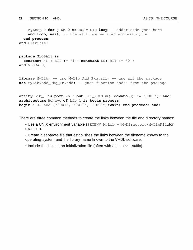
MyLoop : for j in 0 to BUSWIDTH loop -- adder code goes here end loop; wait; -- the wait prevents an endless cycle end process;end Flexible;
package GLOBALS is constant HI : BIT := '1'; constant LO: BIT := '0';end GLOBALS;
library MyLib; -- use MyLib.Add_Pkg.all; -- use all the packageuse MyLib.Add_Pkg_Fn.add; -- just function 'add' from the package
entity Lib_1 is port (s : out BIT_VECTOR(3 downto 0) := "0000"); end;architecture Behave of Lib_1 is begin processbegin s <= add ("0001", "0010", "1000"); wait; end process; end;
There are three common methods to create the links between the file and directory names:
• Use a UNIX environment variable (SETENV MyLib ~/MyDirectory/MyLibFile, forexample).
• Create a separate file that establishes the links between the filename known to theoperating system and the library name known to the VHDL software.
• Include the links in an initialization file (often with an '.ini' suffix).
ASICs... THE COURSE 10.7 Interface Declarations 23
10.7 Interface Declarations
Key terms: interface declaration • formals • locals • actuals • interface objects (constants,
signals, variables, or files) • interface constants (generics of a design entity, a component, or a
block, or parameters of subprograms) • interface signals (ports of a design entity, component, or
block, and parameters of subprograms) • interface variables and interface files (parameters of
subprograms) • interface object mode (in,the default, out, inout, buffer, linkage) • read
• update • interface object rules (“i before e”), there are also mode rules (“except after c”)
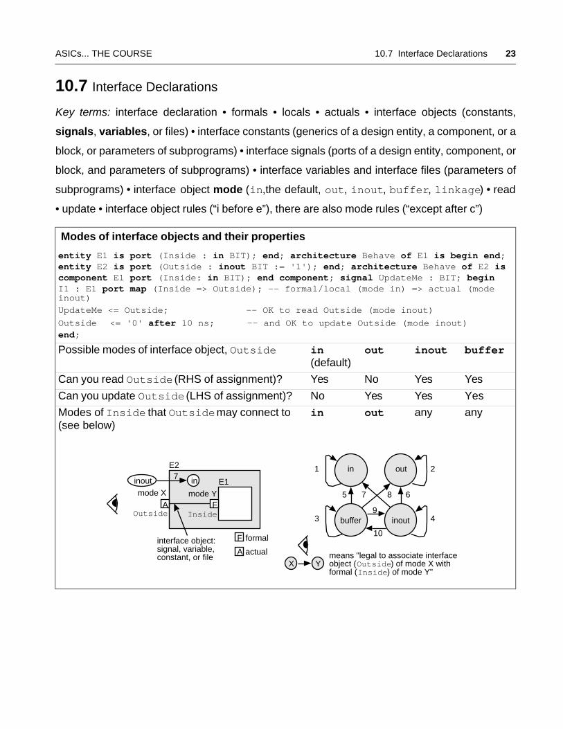
Modes of interface objects and their properties
entity E1 is port (Inside : in BIT); end; architecture Behave of E1 is begin end;entity E2 is port (Outside : inout BIT := '1'); end; architecture Behave of E2 is component E1 port (Inside: in BIT); end component; signal UpdateMe : BIT; begin I1 : E1 port map (Inside => Outside); -- formal/local (mode in) => actual (mode inout)
UpdateMe <= Outside; -- OK to read Outside (mode inout)Outside <= '0' after 10 ns; -- and OK to update Outside (mode inout)end;
Possible modes of interface object, Outside in (default)
out inout buffer
Can you read Outside (RHS of assignment)? Yes No Yes Yes
Can you update Outside (LHS of assignment)? No Yes Yes Yes
Modes of Inside that Outside may connect to (see below)
in out any any
mode Y
E2
InsideOutside
means "legal to associate interfaceobject (Outside) of mode X withformal (Inside) of mode Y"
mode X
interface object:signal, variable,constant, or file
E1
F
F formal
A
A actual
ininout
1 2
3 4
5 67 8
9
10
7
inout
outin
buffer
X Y
24 SECTION 10 VHDL ASICS... THE COURSE
10.7.1 Port Declaration
Key terms: ports (connectors)• port interface declaration • formals • locals • actuals • implicit
signal declaration • port mode • signal kind • default value • default expression • open • port map
• positional association • named association • default binding
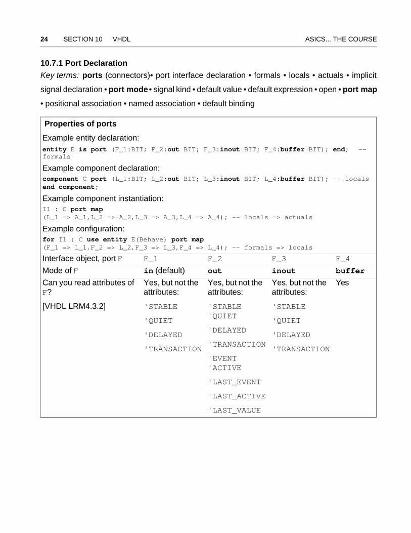
Properties of ports
Example entity declaration:entity E is port (F_1:BIT; F_2:out BIT; F_3:inout BIT; F_4:buffer BIT); end; -- formals
Example component declaration:component C port (L_1:BIT; L_2:out BIT; L_3:inout BIT; L_4:buffer BIT); -- localsend component;
Example component instantiation:I1 : C port map (L_1 => A_1,L_2 => A_2,L_3 => A_3,L_4 => A_4); -- locals => actuals
Example configuration:for I1 : C use entity E(Behave) port map (F_1 => L_1,F_2 => L_2,F_3 => L_3,F_4 => L_4); -- formals => locals
Interface object, port F F_1 F_2 F_3 F_4
Mode of F in (default) out inout buffer
Can you read attributes of F?
[VHDL LRM4.3.2]
Yes, but not the attributes:
'STABLE
'QUIET
'DELAYED
'TRANSACTION
Yes, but not the attributes:
'STABLE 'QUIET
'DELAYED
'TRANSACTION
'EVENT 'ACTIVE
'LAST_EVENT
'LAST_ACTIVE
'LAST_VALUE
Yes, but not the attributes:
'STABLE
'QUIET
'DELAYED
'TRANSACTION
Yes
ASICs... THE COURSE 10.7 Interface Declarations 25
port (port_interface_list)
interface_list ::= port_interface_declaration {; port_interface_declaration}
interface_declaration ::= [signal] identifier {, identifier}:[in|out|inout|buffer|linkage] subtype_indication [bus] [:= static_expression]
entity Association_1 is port (signal X, Y : in BIT := '0'; Z1, Z2, Z3 : out BIT);end;
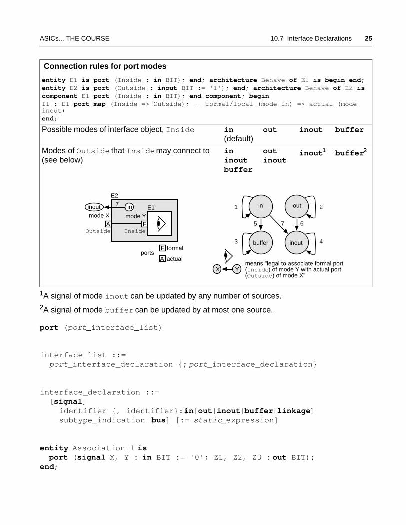
Connection rules for port modes
entity E1 is port (Inside : in BIT); end; architecture Behave of E1 is begin end;entity E2 is port (Outside : inout BIT := '1'); end; architecture Behave of E2 is component E1 port (Inside : in BIT); end component; begin I1 : E1 port map (Inside => Outside); -- formal/local (mode in) => actual (mode inout)end;
Possible modes of interface object, Inside in (default)
out inout buffer
Modes of Outside that Inside may connect to (see below)
in inout buffer
out inout
inout1 buffer2
1A signal of mode inout can be updated by any number of sources.2A signal of mode buffer can be updated by at most one source.
means "legal to associate formal port(Inside) of mode Y with actual port(Outside) of mode X"
mode Y
E2
InsideOutside
mode XE1
F
F formal
A
A actual
ininout
ports
1 2
3 4
5 67
7 outin
inoutbuffer
X Y
26 SECTION 10 VHDL ASICS... THE COURSE
use work.all; -- makes analyzed design entity AndGate(Simple) visible.architecture Netlist of Association_1 is-- The formal port clause for entity AndGate looks like this:-- port (And_in_1, And_in_2: in BIT; And_out : out BIT); -- Formals.component AndGate port (And_in_1, And_in_2 : in BIT; And_out : out BIT); -- Locals.end component;begin-- The component and entity have the same names: AndGate.-- The port names are also the same: And_in_1, And_in_2, And_out,-- so we can use default binding without a configuration.-- The last (and only) architecture for AndGate will be used: Simple.A1:AndGate port map (X, Y, Z1); -- positional associationA2:AndGate port map (And_in_2=>Y, And_out=>Z2, And_in_1=>X); -- namedA3:AndGate port map (X, And_out => Z3, And_in_2 => Y); -- bothend;
entity ClockGen_1 is port (Clock : out BIT); end;architecture Behave of ClockGen_1 isbegin process variable Temp : BIT := '1'; begin-- Clock <= not Clock; -- Illegal, you cannot read Clock (mode out), Temp := not Temp; -- use a temporary variable instead. Clock <= Temp after 10 ns; wait for 10 ns; if (now > 100 ns) then wait; end if; end process;end;
10.7.2 Generics
Key terms: generic (similar to a port) • ports (signals) carry changing information between
entities • generics carry constant, static information • generic interface list
entity AndT is generic (TPD : TIME := 1 ns); port (a, b : BIT := '0'; q: out BIT);end;architecture Behave of AndT is begin q <= a and b after TPD;end;
ASICs... THE COURSE 10.7 Interface Declarations 27
entity AndT_Test_1 is end;architecture Netlist_1 of AndT_Test_1 is component MyAnd port (a, b : BIT; q : out BIT); end component; signal a1, b1, q1 : BIT := '1'; begin And1 : MyAnd port map (a1, b1, q1);end Netlist_1;
configuration Simplest_1 of AndT_Test_1 is use work.all; for Netlist_1 for And1 : MyAnd use entity AndT(Behave) generic map (2 ns); end for; end for;end Simplest_1;
28 SECTION 10 VHDL ASICS... THE COURSE
10.8 Type Declarations
Key terms and concepts: type of an object • VHDL is strongly typed • you cannot add a
temperature of type Centigrade to a temperature of type Fahrenheit • type declaration • range
• precision • subtype • subtype declaration • composite type (array type) • aggregate notation •
record type
There are four type classes: scalar types, composite types, access types, file types
1. Scalar types: integer type, floating-point type, physical type, enumeration type
(integer and enumeration types are discrete types)
(integer, floating-point, and physical types are numeric types)
(physical types correspond to time, voltage, current, and so on and have dimensions)
2. Composite types include array types (and record types)
3. Access types are pointers, good for abstract data structures, less so in ASIC design
4. File types are used for file I/O, not ASIC design
type_declaration ::= type identifier ;| type identifier is (identifier|'graphic_character' {, identifier|'graphic_character'}) ;| range_constraint ; | physical_type_definition ;| record_type_definition ; | access subtype_indication ;| file of type_name ; | file of subtype_name ;| array index_constraint of element_subtype_indication ;| array (type_name|subtype_name range <> {, type_name|subtype_name range <>}) of element_subtype_indication ;
entity Declaration_1 is end; architecture Behave of Declaration_1 istype F is range 32 to 212; -- Integer type, ascending range.type C is range 0 to 100; -- Range 0 to 100 is the range constraint.subtype G is INTEGER range 9 to 0; -- Base type INTEGER, descending.-- This is illegal: type Bad100 is INTEGER range 0 to 100; -- don't use INTEGER in declaration of type (but OK in subtype).type Rainbow is (R, O, Y, G, B, I, V); -- An enumeration type.-- Enumeration types always have an ascending range.type MVL4 is ('X', '0', '1', 'Z');
ASICs... THE COURSE 10.8 Type Declarations 29
-- Note that 'X' and 'x' are different character literals.-- The default initial value is MVL4'LEFT = 'X'.-- We say '0' and '1' (already enumeration literals-- for predefined type BIT) are overloaded.-- Illegal enumeration type: type Bad4 is ("X", "0", "1", "Z"); -- Enumeration literals must be character literals or identifiers.begin end;
entity Arrays_1 is end; architecture Behave of Arrays_1 istype Word is array (0 to 31) of BIT; -- a 32-bit array, ascendingtype Byte is array (NATURAL range 7 downto 0) of BIT; -- descendingtype BigBit is array (NATURAL range <>) of BIT;-- We call <> a box, it means the range is undefined for now.-- We call BigBit an unconstrained array.-- This is OK, we constrain the range of an object that uses-- type BigBit when we declare the object, like this:subtype Nibble is BigBit(3 downto 0);type T1 is array (POSITIVE range 1 to 32) of BIT;-- T1, a constrained array declaration, is equivalent to a type T2 -- with the following three declarations:subtype index_subtype is POSITIVE range 1 to 32;type array_type is array (index_subtype range <>) of BIT;subtype T2 is array_type (index_subtype);-- We refer to index_subtype and array_type as being-- anonymous subtypes of T1 (since they don't really exist).begin end;
entity Aggregate_1 is end; architecture Behave of Aggregate_1 istype D is array (0 to 3) of BIT; type Mask is array (1 to 2) of BIT;signal MyData : D := ('0', others => '1'); -- positional aggregate signal MyMask : Mask := (2 => '0', 1 => '1'); -- named aggregatebegin end;
entity Record_2 is end; architecture Behave of Record_2 is type Complex is record real : INTEGER; imag : INTEGER; end record;signal s1 : Complex := (0, others => 1); signal s2: Complex;begin s2 <= (imag => 2, real => 1); end;
30 SECTION 10 VHDL ASICS... THE COURSE
10.9 Other Declarations
Key concepts: (we already covered entity, configuration, component, package, interface, type,
and subtype declarations)
• objects: constant, variable, signal, file
• alias (user-defined “monikers”)
• attributes (user-defined and tool-vendor defined)
• subprograms: functions and procedures
• groups and group templates are new to VHDL-93 and hardly used in ASIC design
declaration ::= type_declaration | subtype_declaration | object_declaration| interface_declaration | alias_declaration | attribute_declaration| component_declaration | entity_declaration| configuration_declaration | subprogram_declaration| package_declaration| group_template_declaration | group_declaration
10.9.1 Object Declarations
Key terms and concepts: class of an object • declarative region (before the first begin) • declare
a type with (explicit) initial value • (implicit) default initial value is T'LEFT • explicit signal decla-
rations • shared variable
There are four object classes: constant, variable, signal, file
You use a constant declaration, signal declaration, variable declaration, or file declaration
together with a type
Signals represent real wires in hardware
Variables are memory locations in a computer
entity Initial_1 is end; architecture Behave of Initial_1 istype Fahrenheit is range 32 to 212; -- Default initial value is 32.type Rainbow is (R, O, Y, G, B, I, V); -- Default initial value is R.type MVL4 is ('X', '0', '1', 'Z'); -- MVL4'LEFT = 'X'.begin end;
ASICs... THE COURSE 10.9 Other Declarations 31
constant_declaration ::= constantidentifier {, identifier}:subtype_indication [:= expression] ;
signal_declaration ::= signalidentifier {, identifier}:subtype_indication [register|bus] [:=expression];
entity Constant_2 is end; library IEEE; use IEEE.STD_LOGIC_1164.all;architecture Behave of Constant_2 isconstant Pi : REAL := 3.14159; -- A constant declaration.signal B : BOOLEAN; signal s1, s2: BIT; signal sum : INTEGER range 0 to 15; -- Not a new type.signal SmallBus : BIT_VECTOR(15 downto 0); -- 16-bit bus.signal GBus : STD_LOGIC_VECTOR(31 downto 0) bus; -- A guarded signal.begin end;
variable_declaration ::= [shared] variableidentifier {, identifier}:subtype_indication [:= expression] ;
library IEEE; use IEEE.STD_LOGIC_1164.all; entity Variables_1 is end;architecture Behave of Variables_1 is begin process variable i : INTEGER range 1 to 10 := 10; -- Initial value = 10. variable v : STD_LOGIC_VECTOR (0 to 31) := (others => '0'); begin wait; end process; -- The wait stops an endless cycle.end;
32 SECTION 10 VHDL ASICS... THE COURSE
10.9.2 Subprogram Declarations
Key terms and concepts: subprogram • function • procedure • subprogram declaration: a
function declaration or a procedure declaration • formal parameters (or formals) • subprogram
invocation • actual parameters (or actuals) • impure function (now) • pure function (default) •
subprogram specification • subprogram body • conform • private
subprogram_declaration ::= subprogram_specification ; ::= procedure identifier|string_literal [(parameter_interface_list)]
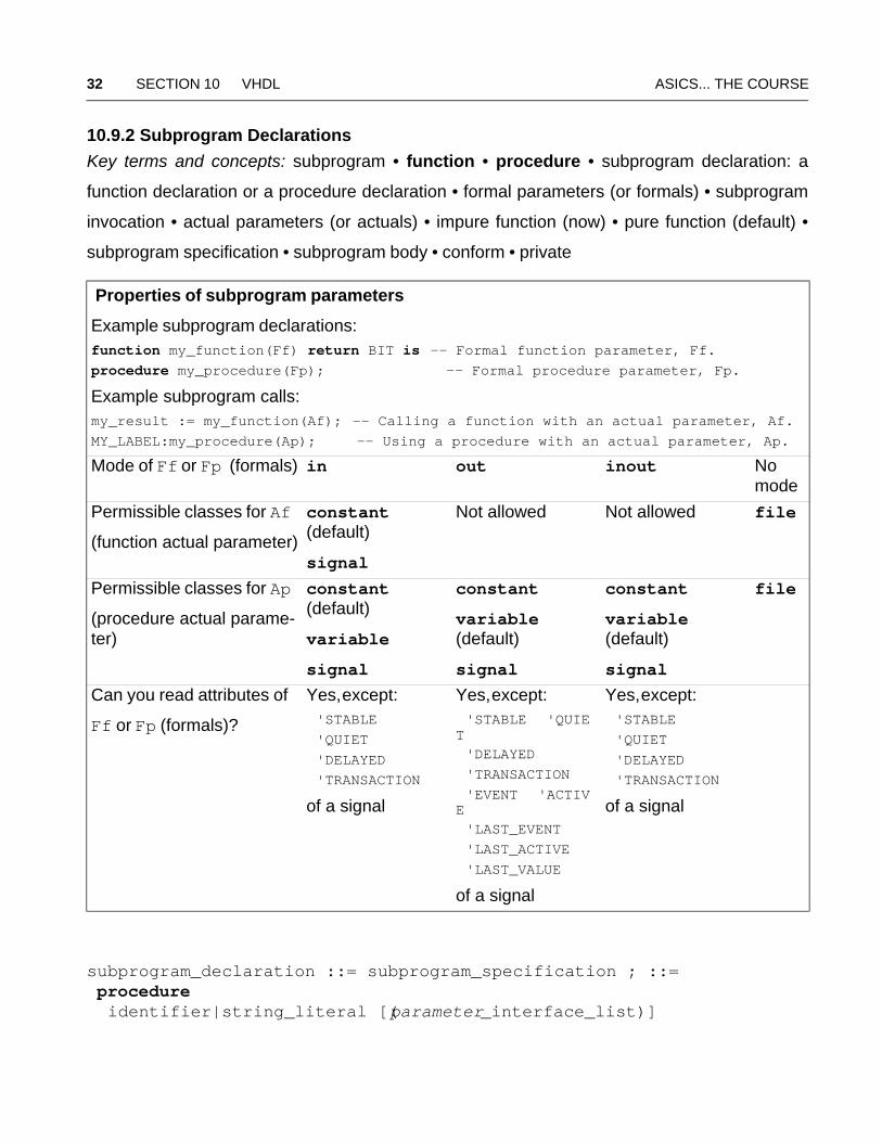
Properties of subprogram parameters
Example subprogram declarations:function my_function(Ff) return BIT is -- Formal function parameter, Ff.procedure my_procedure(Fp); -- Formal procedure parameter, Fp.
Example subprogram calls:my_result := my_function(Af); -- Calling a function with an actual parameter, Af.MY_LABEL:my_procedure(Ap); -- Using a procedure with an actual parameter, Ap.
Mode of Ff or Fp (formals) in out inout No mode
Permissible classes for Af
(function actual parameter)
constant (default)
signal
Not allowed Not allowed file
Permissible classes for Ap
(procedure actual parame-ter)
constant (default)
variable
signal
constant
variable (default)
signal
constant
variable (default)
signal
file
Can you read attributes of
Ff or Fp (formals)?
Yes, except: 'STABLE 'QUIET 'DELAYED 'TRANSACTION
of a signal
Yes, except: 'STABLE 'QUIET
'DELAYED 'TRANSACTION 'EVENT 'ACTIVE
'LAST_EVENT 'LAST_ACTIVE 'LAST_VALUE
of a signal
Yes, except: 'STABLE 'QUIET 'DELAYED 'TRANSACTION
of a signal
ASICs... THE COURSE 10.9 Other Declarations 33
| [pure|impure] function identifier|string_literal [(parameter_interface_list)]return type_name|subtype_name;
function add(a, b, c : BIT_VECTOR(3 downto 0)) return BIT_VECTOR is-- A function declaration, a function can't modify a, b, or c.
procedure Is_A_Eq_B (signal A, B : BIT; signal Y : out BIT);-- A procedure declaration, a procedure can change Y.
subprogram_body ::= subprogram_specification is {subprogram_declaration|subprogram_body |type_declaration|subtype_declaration |constant_declaration|variable_declaration|file_declaration |alias_declaration|attribute_declaration|attribute_specification |use_clause|group_template_declaration|group_declaration} begin {sequential_statement} end [procedure|function] [identifier|string_literal] ;
function subset0(sout0 : in BIT) return BIT_VECTOR -- declaration
-- Declaration can be separate from the body.
function subset0(sout0 : in BIT) return BIT_VECTOR is -- bodyvariable y : BIT_VECTOR(2 downto 0);begin if (sout0 = '0') then y := "000"; else y := "100"; end if;return result;end;
procedure clockGen (clk : out BIT) -- Declaration
procedure clockGen (clk : out BIT) is -- Specificationbegin -- Careful this process runs forever: process begin wait for 10 ns; clk <= not clk; end process;end;
34 SECTION 10 VHDL ASICS... THE COURSE
entity F_1 is port (s : out BIT_VECTOR(3 downto 0) := "0000"); end;architecture Behave of F_1 is begin processfunction add(a, b, c : BIT_VECTOR(3 downto 0)) return BIT_VECTOR isbegin return a xor b xor c; end;begin s <= add("0001", "0010", "1000"); wait; end process; end;
package And_Pkg is procedure V_And(a, b : BIT; signal c : out BIT); function V_And(a, b : BIT) return BIT;end;
package body And_Pkg is procedure V_And(a,b : BIT;signal c : out BIT) is begin c <= a and b; end; function V_And(a,b : BIT) return BIT is begin return a and b; end;end And_Pkg;
entity F_2 is port (s: out BIT := '0'); end;use work.And_Pkg.all; -- use package already analyzedarchitecture Behave of F_2 is begin process begin s <= V_And('1', '1'); wait; end process; end;
10.9.3 Alias and Attribute Declarations
alias_declaration ::= alias identifier|character_literal|operator_symbol [ :subtype_indication] is name [signature];
entity Alias_1 is end; architecture Behave of Alias_1 isbegin process variable Nmbr: BIT_VECTOR (31 downto 0);-- alias declarations to split Nmbr into 3 pieces :alias Sign : BIT is Nmbr(31);alias Mantissa : BIT_VECTOR (23 downto 0) is Nmbr (30 downto 7);alias Exponent : BIT_VECTOR ( 6 downto 0) is Nmbr ( 6 downto 0);begin wait; end process; end; -- the wait prevents an endless cycle
ASICs... THE COURSE 10.9 Other Declarations 35
attribute_declaration ::= attribute identifier:type_name ; | attribute identifier:subtype_name ;
entity Attribute_1 is end; architecture Behave of Attribute_1 isbegin process type COORD is record X, Y : INTEGER; end record; attribute LOCATION : COORD; -- the attribute declarationbegin wait ; -- the wait prevents an endless cycleend process; end;
You define the attribute properties in an attribute specification:
attribute LOCATION of adder1 : label is (10,15);
positionOfComponent := adder1'LOCATION;
36 SECTION 10 VHDL ASICS... THE COURSE
10.9.4 Predefined Attributes
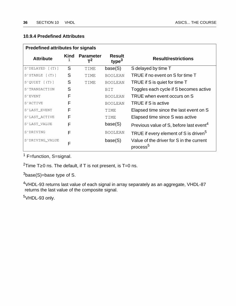
Predefined attributes for signals
Attribute Kind1
1 F=function, S=signal.
Parameter T2
2Time T≥0 ns. The default, if T is not present, is T=0 ns.
Result type3
3base(S)=base type of S.
Result/restrictions
S'DELAYED [(T)] S TIME base(S) S delayed by time TS'STABLE [(T)] S TIME BOOLEAN TRUE if no event on S for time TS'QUIET [(T)] S TIME BOOLEAN TRUE if S is quiet for time TS'TRANSACTION S BIT Toggles each cycle if S becomes active S'EVENT F BOOLEAN TRUE when event occurs on SS'ACTIVE F BOOLEAN TRUE if S is active S'LAST_EVENT F TIME Elapsed time since the last event on SS'LAST_ACTIVE F TIME Elapsed time since S was activeS'LAST_VALUE F base(S) Previous value of S, before last event4
4VHDL-93 returns last value of each signal in array separately as an aggregate, VHDL-87 returns the last value of the composite signal.
S'DRIVING F BOOLEAN TRUE if every element of S is driven5
5VHDL-93 only.
S'DRIVING_VALUE F
base(S) Value of the driver for S in the current process5
ASICs... THE COURSE 10.9 Other Declarations 37
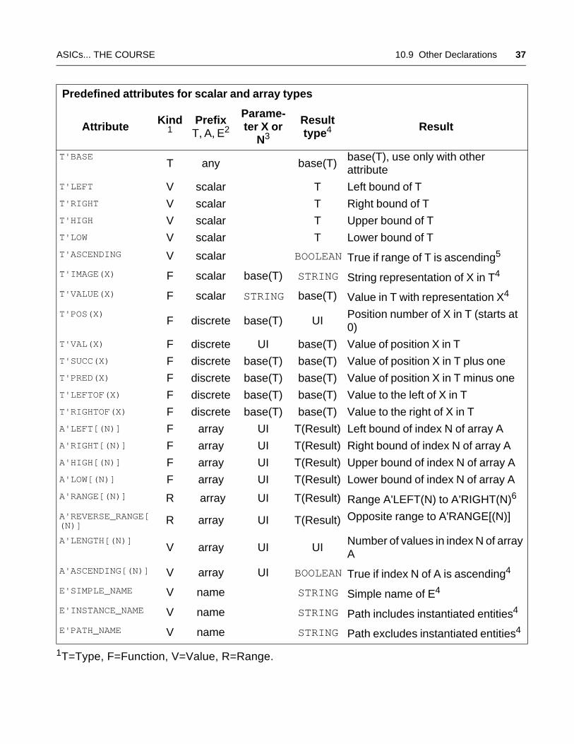
Predefined attributes for scalar and array types
Attribute Kind1
Prefix T, A, E2
Parame-ter X or
N3
Result type4 Result
T'BASE T any base(T)
base(T), use only with other attribute
T'LEFT V scalar T Left bound of T T'RIGHT V scalar T Right bound of T T'HIGH V scalar T Upper bound of T T'LOW V scalar T Lower bound of T T'ASCENDING V scalar BOOLEAN True if range of T is ascending5 T'IMAGE(X) F scalar base(T) STRING String representation of X in T4
T'VALUE(X) F scalar STRING base(T) Value in T with representation X4
T'POS(X) F discrete base(T) UI
Position number of X in T (starts at 0)
T'VAL(X) F discrete UI base(T) Value of position X in TT'SUCC(X) F discrete base(T) base(T) Value of position X in T plus one T'PRED(X) F discrete base(T) base(T) Value of position X in T minus one T'LEFTOF(X) F discrete base(T) base(T) Value to the left of X in TT'RIGHTOF(X) F discrete base(T) base(T) Value to the right of X in TA'LEFT[(N)] F array UI T(Result) Left bound of index N of array AA'RIGHT[(N)] F array UI T(Result) Right bound of index N of array AA'HIGH[(N)] F array UI T(Result) Upper bound of index N of array AA'LOW[(N)] F array UI T(Result) Lower bound of index N of array AA'RANGE[(N)] R array UI T(Result) Range A'LEFT(N) to A'RIGHT(N)6
A'REVERSE_RANGE[(N)] R array UI T(Result) Opposite range to A'RANGE[(N)]
A'LENGTH[(N)] V array UI UI
Number of values in index N of array A
A'ASCENDING[(N)] V array UI BOOLEAN True if index N of A is ascending4
E'SIMPLE_NAME V name STRING Simple name of E4
E'INSTANCE_NAME V name STRING Path includes instantiated entities4
E'PATH_NAME V name STRING Path excludes instantiated entities4
1T=Type, F=Function, V=Value, R=Range.
38 SECTION 10 VHDL ASICS... THE COURSE
2any=any type or subtype, scalar=scalar type or subtype, discrete=discrete or physical type or subtype, name=entity name=identifier, character literal, or operator symbol.
3base(T)=base type of T, T=type of T, UI= universal_integer,T(Result)=type of object described in result column.
4base(T)=base type of T, T=type of T, UI= universal_integer,T(Result)=type of object described in result column.
5Only available in VHDL-93. For 'ASCENDING all enumeration types are ascending.6Or reverse for descending ranges.
ASICs... THE COURSE 10.10 Sequential Statements 39
10.10 Sequential Statements
sequential_statement ::= wait_statement | assertion_statement| signal_assignment_statement| variable_assignment_statement | procedure_call_statement| if_statement | case_statement | loop_statement| next_statement | exit_statement| return_statement | null_statement | report_statement
10.10.1 Wait Statement
Key terms and concepts: suspending (stopping) a process or procedure • sensitivity to events
(changes) on static signals • sensitivity clause contains sensitivity list after on • process
resumes at event on signal in the sensitivity set • condition clause after until • timeout
(after for)
wait on light
makes you wait until a traffic light changes (any change)wait until light = green
makes you wait (even at a green light) until the traffic signal changes to greenif light = (red or yellow) then wait until light = green; end if;
describes the basic rules at a traffic intersection
wait_statement ::= [label:] wait [sensitivity_clause] [condition_clause] [timeout_clause] ;sensitivity_clause ::= on sensitivity_listsensitivity_list ::= signal_name { , signal_name }condition_clause ::= until conditioncondition ::= boolean_expressiontimeout_clause ::= for time_expression
wait_statement ::= [label:] wait [on signal_name {, signal_name}] [until boolean_expression] [for time_expression] ;
entity DFF is port (CLK, D : BIT; Q : out BIT); end; --1architecture Behave of DFF is --2
40 SECTION 10 VHDL ASICS... THE COURSE
process begin wait until Clk = '1'; Q <= D ; end process; --3end; --4
entity Wait_1 is port (Clk, s1, s2 :in BIT); end; architecture Behave of Wait_1 issignal x : BIT_VECTOR (0 to 15); begin process variable v : BIT; begin wait; -- Wait forever, stops simulation. wait on s1 until s2 = '1'; -- Legal, but s1, s2 are signals so -- s1 is in sensitivity list, and s2 is not in the sensitivity set. -- Sensitivity set is s1 and process will not resume at event on s2. wait on s1, s2; -- resumes at event on signal s1 or s2. wait on s1 for 10 ns; -- resumes at event on s1 or after 10 ns. wait on x; -- resumes when any element of array x -- has an event.-- wait on x(1 to v); -- Illegal, nonstatic name, since v is a variable.end process;end;
entity Wait_2 is port (Clk, s1, s2:in BIT); end;architecture Behave of Wait_2 is begin process variable v : BIT; begin wait on Clk; -- resumes when Clk has an event: rising or falling. wait until Clk = '1'; -- resumes on rising edge. wait on Clk until Clk = '1'; -- equivalent to the last statement. wait on Clk until v = '1'; -- The above is legal, but v is a variable so -- Clk is in sensitivity list, v is not in the sensitivity set. -- Sensitivity set is Clk and process will not resume at event on v. wait on Clk until s1 = '1'; -- The above is legal, but s1 is a signal so -- Clk is in sensitivity list, s1 is not in the sensitivity set. -- Sensitivity set is Clk, process will not resume at event on s1. end process;end;
ASICs... THE COURSE 10.10 Sequential Statements 41
10.10.2 Assertion and Report Statements
assertion_statement ::= [label:] assertboolean_expression [report expression] [severity expression] ;
report_statement ::= [label:] report expression [severity expression] ;
entity Assert_1 is port (I:INTEGER:=0); end;architecture Behave of Assert_1 is begin process begin assert (I > 0) report "I is negative or zero"; wait; end process;end;
10.10.3 Assignment Statements
Key terms and concepts: A variable assignment statement updates immediately • A signal
assignment statement schedules a future assignment • simulation cycle • delta cycle • delta
time • delta, δ • event • delay models: transport and inertial delay (the default) • pulse rejection
limit
variable_assignment_statement ::= [label:] name|aggregate := expression ;
entity Var_Assignment is end;architecture Behave of Var_Assignment is signal s1 : INTEGER := 0; begin process variable v1,v2 : INTEGER := 0; begin assert (v1/=0) report "v1 is 0" severity note ; -- this prints v1 := v1 + 1; -- after this statement v1 is 1 assert (v1=0) report "v1 isn't 0" severity note ; -- this prints v2 := v2 + s1; -- signal and variable types must match wait; end process;end;
42 SECTION 10 VHDL ASICS... THE COURSE
signal_assignment_statement::= [label:] target <= [transport | [ reject time_expression ] inertial] waveform ;
entity Sig_Assignment_1 is end; architecture Behave of Sig_Assignment_1 is signal s1,s2,s3 : INTEGER := 0; begin process variable v1 : INTEGER := 1; begin assert (s1 /= 0) report "s1 is 0" severity note ; -- this prints. s1 <= s1 + 1; -- after this statement s1 is still 0. assert (s1 /= 0) report "s1 still 0" severity note ; -- this prints. wait; end process;end;
entity Sig_Assignment_2 is end; architecture Behave of Sig_Assignment_2 is signal s1, s2, s3 : INTEGER := 0; begin process variable v1 : INTEGER := 1; begin -- s1, s2, s3 are initially 0; now consider the following: s1 <= 1 ; -- schedules updates to s1 at end of 0 ns cycle. s2 <= s1; -- s2 is 0, not 1. wait for 1 ns; s3 <= s1; -- now s3 will be 1 at 1 ns. wait; end process;end;
entity Transport_1 is end; architecture Behave of Transport_1 issignal s1, SLOW, FAST, WIRE : BIT := '0'; begin process begin s1 <= '1' after 1 ns, '0' after 2 ns, '1' after 3 ns ; -- schedules s1 to be '1' at t+1 ns, '0' at t+2 ns,'1' at t+3 ns wait; end process;-- inertial delay: SLOW rejects pulsewidths less than 5ns:process (s1) begin SLOW <= s1 after 5 ns ; end process;-- inertial delay: FAST rejects pulsewidths less than 0.5ns:process (s1) begin FAST <= s1 after 0.5 ns ; end process;-- transport delay: WIRE passes all pulsewidths...
ASICs... THE COURSE 10.10 Sequential Statements 43
process (s1) begin WIRE <= transport s1 after 5 ns ; end process;end;
process (s1) begin RJCT <= reject 2 ns s1 after 5 ns ; end process;
10.10.4 Procedure Call
procedure_call_statement ::= [label:] procedure_name [(parameter_association_list)];
package And_Pkg is procedure V_And(a, b : BIT; signal c : out BIT); function V_And(a, b : BIT) return BIT;end;
package body And_Pkg is procedure V_And(a, b : BIT; signal c: out BIT) is begin c <= a and b; end; function V_And(a, b: BIT) return BIT is begin return a and b; end;end And_Pkg;
use work.And_Pkg.all; entity Proc_Call_1 is end; architecture Behave of Proc_Call_1 is signal A, B, Y: BIT := '0'; begin process begin V_And (A, B, Y); wait; end process;end;
10.10.5 If Statement
if_statement ::= [if_label:] if boolean_expression then {sequential_statement} {elsif boolean_expression then {sequential_statement}} [else {sequential_statement}] end if [if_label];
entity If_Then_Else_1 is end; architecture Behave of If_Then_Else_1 is signal a, b, c: BIT :='1';
44 SECTION 10 VHDL ASICS... THE COURSE
begin process begin if c = '1' then c <= a ; else c <= b; end if; wait; end process;end;
entity If_Then_1 is end; architecture Behave of If_Then_1 is signal A, B, Y : BIT :='1'; begin process begin if A = B then Y <= A; end if; wait; end process;end;
10.10.6 Case Statement
case_statement ::=[case_label:] case expression is when choice {| choice} => {sequential_statement} {when choice {| choice} => {sequential_statement}}end case [case_label];
library IEEE; use IEEE.STD_LOGIC_1164.all; --1entity sm_mealy is --2 port (reset, clock, i1, i2 : STD_LOGIC; o1, o2 : out STD_LOGIC); --3end sm_mealy; --4architecture Behave of sm_mealy is --5type STATES is (s0, s1, s2, s3); signal current, new : STATES; --6begin --7synchronous : process (clock, reset) begin --8 if To_X01(reset) = '0' then current <= s0; --9 elsif rising_edge(clock) then current <= new; end if; --10end process; --11combinational : process (current, i1, i2) begin --12case current is --13 when s0 => --14 if To_X01(i1) = '1' then o2 <='0'; o1 <='0'; new <= s2; --15 else o2 <= '1'; o1 <= '1'; new <= s1; end if; --16 when s1 => --17 if To_X01(i2) = '1' then o2 <='1'; o1 <='0'; new <= s1; --18 else o2 <='0'; o1 <='1'; new <= s3; end if; --19 when s2 => --20 if To_X01(i2) = '1' then o2 <='0'; o1 <='1'; new <= s2; --21
ASICs... THE COURSE 10.10 Sequential Statements 45
else o2 <= '1'; o1 <= '0'; new <= s0; end if; --22 when s3 => o2 <= '0'; o1 <= '0'; new <= s0; --23 when others => o2 <= '0'; o1 <= '0'; new <= s0; --24end case; --25end process; --26end Behave; --27
46 SECTION 10 VHDL ASICS... THE COURSE
10.10.7 Other Sequential Control Statements
loop_statement ::=[loop_label:] [while boolean_expression|for identifier in discrete_range]loop {sequential_statement}end loop [loop_label];
package And_Pkg is function V_And(a, b : BIT) return BIT; end;
package body And_Pkg is function V_And(a, b : BIT) return BIT is begin return a and b; end; end And_Pkg;
entity Loop_1 is port (x, y : in BIT := '1'; s : out BIT := '0'); end;use work.And_Pkg.all; architecture Behave of Loop_1 is begin loop s <= V_And(x, y); wait on x, y; end loop; end;
The next statement [VHDL LRM8.10] forces completion of current loop iteration:
next_statement ::=[label:] next [loop_label] [when boolean_expression];
An exit statement [VHDL LRM8.11] forces an exit from a loop.
exit_statement ::= [label:] exit [loop_label] [when condition] ;
ASICs... THE COURSE 10.10 Sequential Statements 47
loop wait on Clk; exit when Clk = '0'; end loop;-- equivalent to: wait until Clk = '0';
The return statement [VHDL LRM8.12] completes execution of a procedure or function:
return_statement ::= [label:] return [expression];
A null statement [VHDL LRM8.13] does nothing:
null_statement ::= [label:] null;
48 SECTION 10 VHDL ASICS... THE COURSE
10.11 Operators
entity Operator_1 is end; architecture Behave of Operator_1 is --1begin process --2variable b : BOOLEAN; variable bt : BIT := '1'; variable i : INTEGER;--3variable pi : REAL := 3.14; variable epsilon : REAL := 0.01; --4variable bv4 : BIT_VECTOR (3 downto 0) := "0001"; --5variable bv8 : BIT_VECTOR (0 to 7); --6begin --7
b := "0000" < bv4; -- b is TRUE, "0000" treated as BIT_VECTOR. --8b := 'f' > 'g'; -- b is FALSE, 'dictionary' comparison. --9bt := '0' and bt; -- bt is '0', analyzer knows '0' is BIT. --10bv4 := not bv4; -- bv4 is now "1110". --11i := 1 + 2; -- Addition, must be compatible types. --12i := 2 ** 3; -- Exponentiation, exponent must be integer. --13i := 7/3; -- Division, L/R rounded towards zero, i=2. --14i := 12 rem 7; -- Remainder, i=5. In general: --15 -- L rem R = L-((L/R)*R). --16i := 12 mod 7; -- modulus, i=5. In general: --17 -- L mod R = L-(R*N) for an integer N. --18
-- shift := sll | srl | sla | sra | rol | ror (VHDL-93 only) --19bv4 := "1001" srl 2; -- Shift right logical, now bv4="0100". --20-- Logical shift fills with T'LEFT. --21bv4 := "1001" sra 2; -- Shift right arithmetic, now bv4="0111". --22-- Arithmetic shift fills with element at end being vacated. --23bv4 := "1001" ror 2; -- Rotate right, now bv4="0110". --24-- Rotate wraps around. --25-- Integer argument to any shift operator may be negative or zero.--26
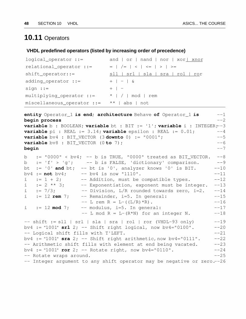
VHDL predefined operators (listed by increasing order of precedence)
logical_operator ::= and | or | nand | nor | xor | xnor
relational_operator ::= = | /= | < | <= | > | >=
shift_operator::= sll | srl | sla | sra | rol | ror
adding_operator ::= + | – | &
sign ::= + | –
multiplying_operator ::= * | / | mod | rem
miscellaneous_operator ::= ** | abs | not
ASICs... THE COURSE 10.12 Arithmetic 49
if (pi*2.718)/2.718 = 3.14 then wait; end if; -- This is unreliable.--27if (abs(((pi*2.718)/2.718)-3.14)<epsilon) then wait; end if; -- Better. --28
bv8 := bv8(1 to 7) & bv8(0); -- Concatenation, a left rotation. --29
wait; end process; --30end; --31
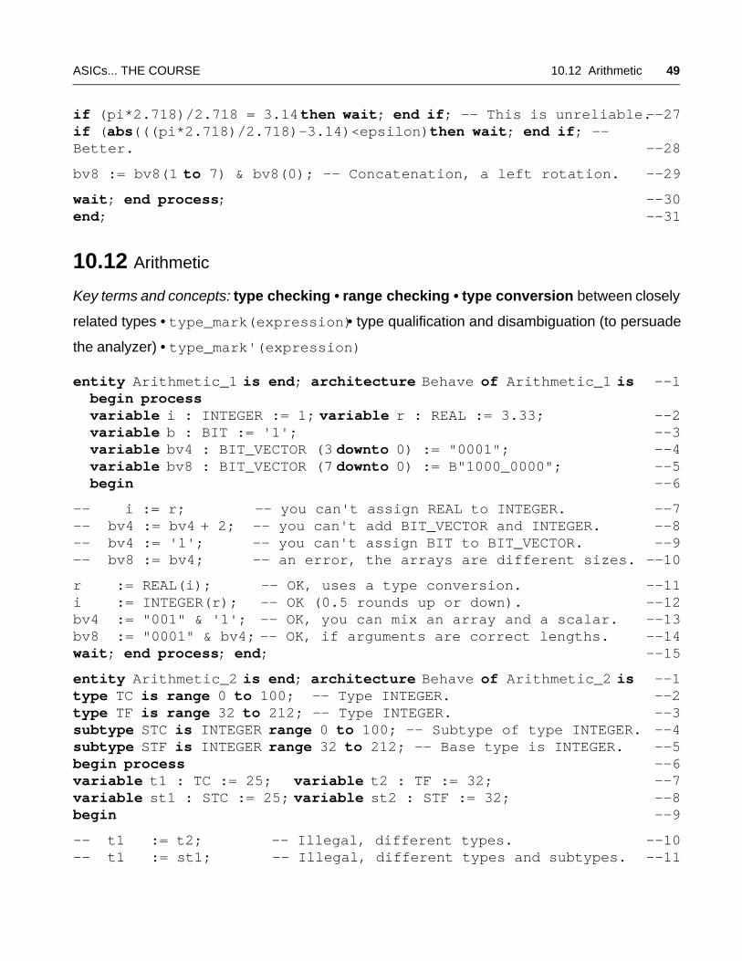
10.12 Arithmetic
Key terms and concepts: type checking • range checking • type conversion between closely
related types • type_mark(expression)• type qualification and disambiguation (to persuade
the analyzer) • type_mark'(expression)
entity Arithmetic_1 is end; architecture Behave of Arithmetic_1 is --1 begin process variable i : INTEGER := 1; variable r : REAL := 3.33; --2 variable b : BIT := '1'; --3 variable bv4 : BIT_VECTOR (3 downto 0) := "0001"; --4 variable bv8 : BIT_VECTOR (7 downto 0) := B"1000_0000"; --5 begin --6
-- i := r; -- you can't assign REAL to INTEGER. --7-- bv4 := bv4 + 2; -- you can't add BIT_VECTOR and INTEGER. --8-- bv4 := '1'; -- you can't assign BIT to BIT_VECTOR. --9-- bv8 := bv4; -- an error, the arrays are different sizes. --10
r := REAL(i); -- OK, uses a type conversion. --11i := INTEGER(r); -- OK (0.5 rounds up or down). --12bv4 := "001" & '1'; -- OK, you can mix an array and a scalar. --13bv8 := "0001" & bv4; -- OK, if arguments are correct lengths. --14wait; end process; end; --15
entity Arithmetic_2 is end; architecture Behave of Arithmetic_2 is --1type TC is range 0 to 100; -- Type INTEGER. --2type TF is range 32 to 212; -- Type INTEGER. --3subtype STC is INTEGER range 0 to 100; -- Subtype of type INTEGER. --4subtype STF is INTEGER range 32 to 212; -- Base type is INTEGER. --5begin process --6variable t1 : TC := 25; variable t2 : TF := 32; --7variable st1 : STC := 25; variable st2 : STF := 32; --8begin --9
-- t1 := t2; -- Illegal, different types. --10-- t1 := st1; -- Illegal, different types and subtypes. --11
50 SECTION 10 VHDL ASICS... THE COURSE
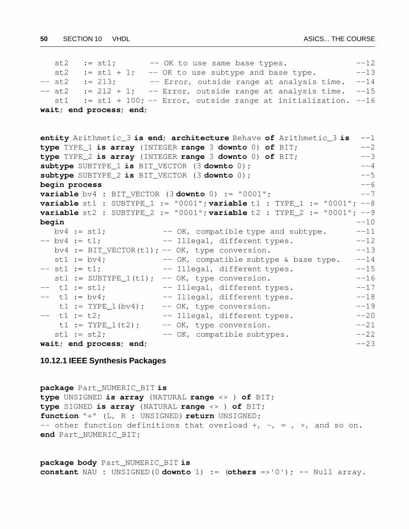
st2 := st1; -- OK to use same base types. --12 st2 := st1 + 1; -- OK to use subtype and base type. --13-- st2 := 213; -- Error, outside range at analysis time. --14-- st2 := 212 + 1; -- Error, outside range at analysis time. --15 st1 := st1 + 100; -- Error, outside range at initialization. --16wait; end process; end;
entity Arithmetic_3 is end; architecture Behave of Arithmetic_3 is --1type TYPE_1 is array (INTEGER range 3 downto 0) of BIT; --2type TYPE_2 is array (INTEGER range 3 downto 0) of BIT; --3subtype SUBTYPE_1 is BIT_VECTOR (3 downto 0); --4subtype SUBTYPE_2 is BIT_VECTOR (3 downto 0); --5begin process --6variable bv4 : BIT_VECTOR (3 downto 0) := "0001"; --7variable st1 : SUBTYPE_1 := "0001"; variable t1 : TYPE_1 := "0001"; --8variable st2 : SUBTYPE_2 := "0001"; variable t2 : TYPE_2 := "0001"; --9begin --10 bv4 := st1; -- OK, compatible type and subtype. --11-- bv4 := t1; -- Illegal, different types. --12 bv4 := BIT_VECTOR(t1); -- OK, type conversion. --13 st1 := bv4; -- OK, compatible subtype & base type. --14-- st1 := t1; -- Illegal, different types. --15 st1 := SUBTYPE_1(t1); -- OK, type conversion. --16-- t1 := st1; -- Illegal, different types. --17-- t1 := bv4; -- Illegal, different types. --18 t1 := TYPE_1(bv4); -- OK, type conversion. --19-- t1 := t2; -- Illegal, different types. --20 t1 := TYPE_1(t2); -- OK, type conversion. --21 st1 := st2; -- OK, compatible subtypes. --22wait; end process; end; --23
10.12.1 IEEE Synthesis Packages
package Part_NUMERIC_BIT istype UNSIGNED is array (NATURAL range <> ) of BIT;type SIGNED is array (NATURAL range <> ) of BIT;function "+" (L, R : UNSIGNED) return UNSIGNED;-- other function definitions that overload +, -, = , >, and so on.end Part_NUMERIC_BIT;
package body Part_NUMERIC_BIT isconstant NAU : UNSIGNED(0 downto 1) := (others =>'0'); -- Null array.
ASICs... THE COURSE 10.12 Arithmetic 51
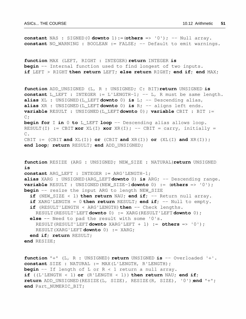
constant NAS : SIGNED(0 downto 1):=(others => '0'); -- Null array.constant NO_WARNING : BOOLEAN := FALSE; -- Default to emit warnings.
function MAX (LEFT, RIGHT : INTEGER) return INTEGER isbegin -- Internal function used to find longest of two inputs.if LEFT > RIGHT then return LEFT; else return RIGHT; end if; end MAX;
function ADD_UNSIGNED (L, R : UNSIGNED; C: BIT) return UNSIGNED isconstant L_LEFT : INTEGER := L'LENGTH-1; -- L, R must be same length.alias XL : UNSIGNED(L_LEFT downto 0) is L; -- Descending alias,alias XR : UNSIGNED(L_LEFT downto 0) is R; -- aligns left ends.variable RESULT : UNSIGNED(L_LEFT downto 0); variable CBIT : BIT := C;begin for I in 0 to L_LEFT loop -- Descending alias allows loop.RESULT(I) := CBIT xor XL(I) xor XR(I); -- CBIT = carry, initially = C.CBIT := (CBIT and XL(I)) or (CBIT and XR(I)) or (XL(I) and XR(I));end loop; return RESULT; end ADD_UNSIGNED;
function RESIZE (ARG : UNSIGNED; NEW_SIZE : NATURAL) return UNSIGNED is constant ARG_LEFT : INTEGER := ARG'LENGTH-1;alias XARG : UNSIGNED(ARG_LEFT downto 0) is ARG; -- Descending range.variable RESULT : UNSIGNED(NEW_SIZE-1 downto 0) := (others => '0');begin -- resize the input ARG to length NEW_SIZE if (NEW_SIZE < 1) then return NAU; end if; -- Return null array. if XARG'LENGTH = 0 then return RESULT; end if; -- Null to empty. if (RESULT'LENGTH < ARG'LENGTH) then -- Check lengths. RESULT(RESULT'LEFT downto 0) := XARG(RESULT'LEFT downto 0); else -- Need to pad the result with some '0's. RESULT(RESULT'LEFT downto XARG'LEFT + 1) := (others => '0'); RESULT(XARG'LEFT downto 0) := XARG; end if; return RESULT;end RESIZE;
function "+" (L, R : UNSIGNED) return UNSIGNED is -- Overloaded '+'.constant SIZE : NATURAL := MAX(L'LENGTH, R'LENGTH);begin -- If length of L or R < 1 return a null array.if ((L'LENGTH < 1) or (R'LENGTH < 1)) then return NAU; end if;return ADD_UNSIGNED(RESIZE(L, SIZE), RESIZE(R, SIZE), '0'); end "+";end Part_NUMERIC_BIT;
52 SECTION 10 VHDL ASICS... THE COURSE
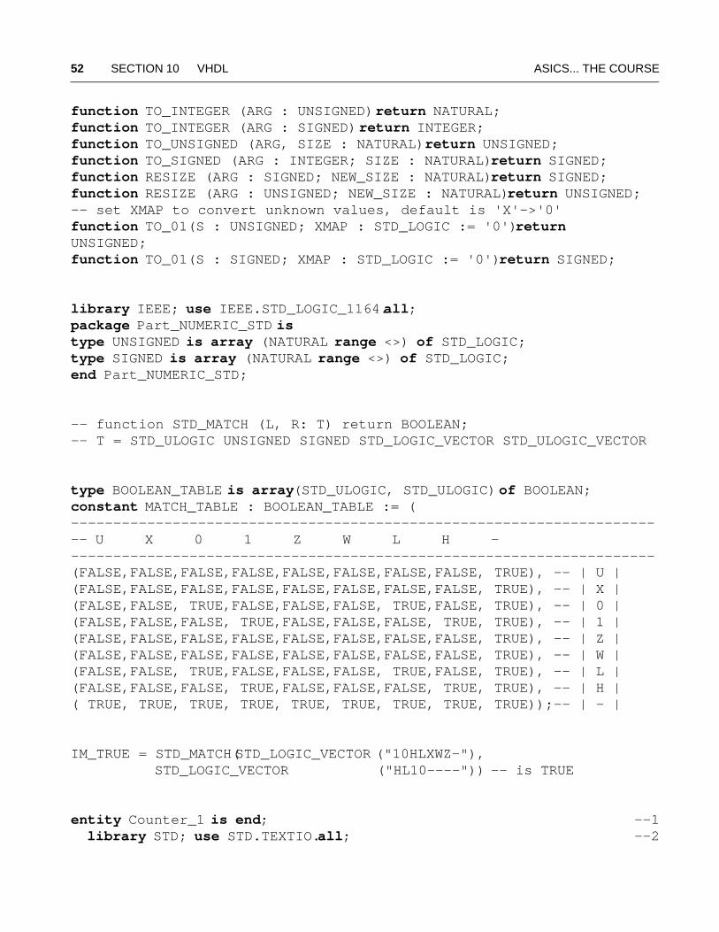
function TO_INTEGER (ARG : UNSIGNED) return NATURAL;function TO_INTEGER (ARG : SIGNED) return INTEGER;function TO_UNSIGNED (ARG, SIZE : NATURAL) return UNSIGNED;function TO_SIGNED (ARG : INTEGER; SIZE : NATURAL) return SIGNED;function RESIZE (ARG : SIGNED; NEW_SIZE : NATURAL) return SIGNED;function RESIZE (ARG : UNSIGNED; NEW_SIZE : NATURAL) return UNSIGNED;-- set XMAP to convert unknown values, default is 'X'->'0'function TO_01(S : UNSIGNED; XMAP : STD_LOGIC := '0') return UNSIGNED;function TO_01(S : SIGNED; XMAP : STD_LOGIC := '0') return SIGNED;
library IEEE; use IEEE.STD_LOGIC_1164.all;package Part_NUMERIC_STD istype UNSIGNED is array (NATURAL range <>) of STD_LOGIC;type SIGNED is array (NATURAL range <>) of STD_LOGIC;end Part_NUMERIC_STD;
-- function STD_MATCH (L, R: T) return BOOLEAN;-- T = STD_ULOGIC UNSIGNED SIGNED STD_LOGIC_VECTOR STD_ULOGIC_VECTOR
type BOOLEAN_TABLE is array(STD_ULOGIC, STD_ULOGIC) of BOOLEAN;constant MATCH_TABLE : BOOLEAN_TABLE := (----------------------------------------------------------------------- U X 0 1 Z W L H ----------------------------------------------------------------------(FALSE,FALSE,FALSE,FALSE,FALSE,FALSE,FALSE,FALSE, TRUE), -- | U | (FALSE,FALSE,FALSE,FALSE,FALSE,FALSE,FALSE,FALSE, TRUE), -- | X | (FALSE,FALSE, TRUE,FALSE,FALSE,FALSE, TRUE,FALSE, TRUE), -- | 0 | (FALSE,FALSE,FALSE, TRUE,FALSE,FALSE,FALSE, TRUE, TRUE), -- | 1 | (FALSE,FALSE,FALSE,FALSE,FALSE,FALSE,FALSE,FALSE, TRUE), -- | Z | (FALSE,FALSE,FALSE,FALSE,FALSE,FALSE,FALSE,FALSE, TRUE), -- | W | (FALSE,FALSE, TRUE,FALSE,FALSE,FALSE, TRUE,FALSE, TRUE), -- | L | (FALSE,FALSE,FALSE, TRUE,FALSE,FALSE,FALSE, TRUE, TRUE), -- | H | ( TRUE, TRUE, TRUE, TRUE, TRUE, TRUE, TRUE, TRUE, TRUE));-- | - |
IM_TRUE = STD_MATCH(STD_LOGIC_VECTOR ("10HLXWZ-"), STD_LOGIC_VECTOR ("HL10----")) -- is TRUE
entity Counter_1 is end; --1 library STD; use STD.TEXTIO.all; --2
ASICs... THE COURSE 10.12 Arithmetic 53
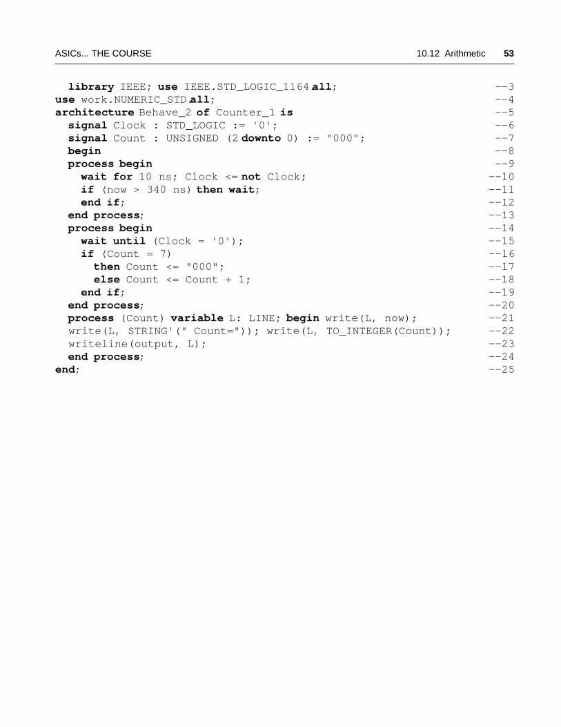
library IEEE; use IEEE.STD_LOGIC_1164.all; --3use work.NUMERIC_STD.all; --4architecture Behave_2 of Counter_1 is --5 signal Clock : STD_LOGIC := '0'; --6 signal Count : UNSIGNED (2 downto 0) := "000"; --7 begin --8 process begin --9 wait for 10 ns; Clock <= not Clock; --10 if (now > 340 ns) then wait; --11 end if; --12 end process; --13 process begin --14 wait until (Clock = '0'); --15 if (Count = 7) --16 then Count <= "000"; --17 else Count <= Count + 1; --18 end if; --19 end process; --20 process (Count) variable L: LINE; begin write(L, now); --21 write(L, STRING'(" Count=")); write(L, TO_INTEGER(Count)); --22 writeline(output, L); --23 end process; --24end; --25
54 SECTION 10 VHDL ASICS... THE COURSE
10.13 Concurrent Statements
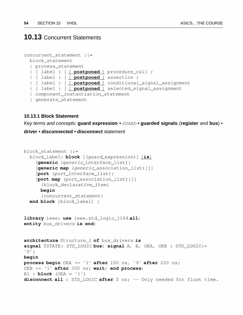
concurrent_statement ::= block_statement | process_statement | [ label : ] [ postponed ] procedure_call ; | [ label : ] [ postponed ] assertion ; | [ label : ] [ postponed ] conditional_signal_assignment | [ label : ] [ postponed ] selected_signal_assignment | component_instantiation_statement | generate_statement
10.13.1 Block Statement
Key terms and concepts: guard expression • GUARD • guarded signals (register and bus) •
driver • disconnected • disconnect statement
block_statement ::= block_label: block [(guard_expression)] [is] [generic (generic_interface_list); [generic map (generic_association_list);]] [port (port_interface_list); [port map (port_association_list);]] {block_declarative_item} begin {concurrent_statement} end block [block_label] ;
library ieee; use ieee.std_logic_1164.all;entity bus_drivers is end;
architecture Structure_1 of bus_drivers issignal TSTATE: STD_LOGIC bus; signal A, B, OEA, OEB : STD_LOGIC:= '0';begin process begin OEA <= '1' after 100 ns, '0' after 200 ns; OEB <= '1' after 300 ns; wait; end process;B1 : block (OEA = '1')disconnect all : STD_LOGIC after 5 ns; -- Only needed for float time.
ASICs... THE COURSE 10.13 Concurrent Statements 55
begin TSTATE <= guarded not A after 3 ns; end block;B2 : block (OEB = '1')disconnect all : STD_LOGIC after 5 ns; -- Float time = 5 ns.begin TSTATE <= guarded not B after 3 ns; end block;end;
architecture Structure_2 of bus_drivers issignal TSTATE : STD_LOGIC; signal A, B, OEA, OEB : STD_LOGIC := '0';begin process beginOEA <= '1' after 100 ns, '0' after 200 ns; OEB <= '1' after 300 ns; wait; end process;process(OEA, OEB, A, B) begin if (OEA = '1') then TSTATE <= not A after 3 ns; elsif (OEB = '1') then TSTATE <= not B after 3 ns; else TSTATE <= 'Z' after 5 ns; end if;end process;end;
10.13.2 Process Statement
Key terms and concepts: process sensitivity set • process execution occurs during a
simulation cycle—made up of delta cycles
process_statement ::=[process_label:][postponed] process [(signal_name {, signal_name})][is] {subprogram_declaration | subprogram_body | type_declaration | subtype_declaration | constant_declaration | variable_declaration | file_declaration | alias_declaration | attribute_declaration | attribute_specification | use_clause | group_declaration | group_template_declaration}begin {sequential_statement}end [postponed] process [process_label];
56 SECTION 10 VHDL ASICS... THE COURSE
entity Mux_1 is port (i0, i1, sel : in BIT := '0'; y : out BIT); end; architecture Behave of Mux_1 is begin process (i0, i1, sel) begin -- i0, i1, sel = sensitivity set case sel is when '0' => y <= i0; when '1' => y <= i1; end case;end process; end;
entity And_1 is port (a, b : in BIT := '0'; y : out BIT); end; architecture Behave of And_1 isbegin process (a, b) begin y <= a and b; end process; end;
entity FF_1 is port (clk, d: in BIT := '0'; q : out BIT); end; architecture Behave of FF_1 isbegin process (clk) begin if clk'EVENT and clk = '1' then q <= d; end if;end process; end;
entity FF_2 is port (clk, d: in BIT := '0'; q : out BIT); end; architecture Behave of FF_2 isbegin process begin -- The equivalent process has a wait at the end: if clk'event and clk = '1' then q <= d; end if; wait on clk;end process; end;
entity FF_3 is port (clk, d: in BIT := '0'; q : out BIT); end; architecture Behave of FF_3 isbegin process begin -- No sensitivity set with a wait statement. wait until clk = '1'; q <= d; end process; end;
10.13.3 Concurrent Procedure Call
package And_Pkg is procedure V_And(a,b:BIT; signal c:out BIT); end;
package body And_Pkg is procedure V_And(a,b:BIT; signal c:out BIT) is begin c <= a and b; end; end And_Pkg;
use work.And_Pkg.all; entity Proc_Call_2 is end; architecture Behave of Proc_Call_2 is signal A, B, Y : BIT := '0';
ASICs... THE COURSE 10.13 Concurrent Statements 57
begin V_And (A, B, Y); -- Concurrent procedure call.process begin wait; end process; -- Extra process to stop.end;
10.13.4 Concurrent Signal Assignment
Key terms and concepts:
There are two forms of concurrent signal assignment statement:
A selected signal assignment statement is equivalent to a case statement inside a
processstatement [VHDL LRM9.5.2].
A conditional signal assignment statement is, in its most general form, equivalent to an if
statement inside a processstatement [VHDL LRM9.5.1].
selected_signal_assignment ::= with expression select name|aggregate <= [guarded] [transport|[reject time_expression] inertial] waveform when choice {| choice} {, waveform when choice {| choice} } ;
entity Selected_1 is end; architecture Behave of Selected_1 issignal y,i1,i2 : INTEGER; signal sel : INTEGER range 0 to 1;begin with sel select y <= i1 when 0, i2 when 1; end;
entity Selected_2 is end; architecture Behave of Selected_2 issignal i1,i2,y : INTEGER; signal sel : INTEGER range 0 to 1;begin process begin case sel is when 0 => y <= i1; when 1 => y <= i2; end case; wait on i1, i2;end process; end;
conditional_signal_assignment ::= name|aggregate <= [guarded] [transport|[reject time_expression] inertial] {waveform when boolean_expression else} waveform [when boolean_expression];
58 SECTION 10 VHDL ASICS... THE COURSE
entity Conditional_1 is end; architecture Behave of Conditional_1 issignal y,i,j : INTEGER; signal clk : BIT;begin y <= i when clk = '1' else j; -- conditional signal assignmentend;
entity Conditional_2 is end; architecture Behave of Conditional_2 issignal y,i : INTEGER; signal clk : BIT;begin process begin if clk = '1' then y <= i; else y <= y ; end if; wait on clk;end process; end;
A concurrent signal assignment statement can look like a sequential signal assignmentstatement:
entity Assign_1 is end; architecture Behave of Assign_1 issignal Target, Source : INTEGER; begin Target <= Source after 1 ns; -- looks like signal assignmentend;
Here is the equivalent process:
entity Assign_2 is end; architecture Behave of Assign_2 issignal Target, Source : INTEGER; begin process begin Target <= Source after 1 ns; wait on Source;end process; end;
entity Assign_3 is end; architecture Behave of Assign_3 issignal Target, Source : INTEGER; begin process begin wait on Source; Target <= Source after 1 ns;end process; end;
10.13.5 Concurrent Assertion Statement
A concurrent assertion statement is equivalent to a passive process statement (withouta sensitivity list) that contains an assertionstatement followed by a wait statement.
ASICs... THE COURSE 10.13 Concurrent Statements 59
concurrent_assertion_statement::= [ label : ] [ postponed ] assertion ;
If the assertion condition contains a signal, then the equivalent process statement willinclude a final wait statement with a sensitivity clause.
A concurrent assertion statement with a condition that is static expression is equivalent to aprocess statement that ends in a wait statement that has no sensitivity clause.
The equivalent process will execute once, at the beginning of simulation, and then waitindefinitely.
10.13.6 Component Instantiation
component_instantiation_statement ::=instantiation_label: [component] component_name |entity entity_name [(architecture_identifier)] |configuration configuration_name [generic map (generic_association_list)] [port map (port_association_list)] ;
entity And_2 is port (i1, i2 : in BIT; y : out BIT); end;architecture Behave of And_2 is begin y <= i1 and i2; end;entity Xor_2 is port (i1, i2 : in BIT; y : out BIT); end;architecture Behave of Xor_2 is begin y <= i1 xor i2; end;
entity Half_Adder_2 is port (a,b : BIT := '0'; sum, cry : out BIT); end;architecture Netlist_2 of Half_Adder_2 isuse work.all; -- need this to see the entities Xor_2 and And_2begin X1 : entity Xor_2(Behave) port map (a, b, sum); -- VHDL-93 only A1 : entity And_2(Behave) port map (a, b, cry); -- VHDL-93 onlyend;
60 SECTION 10 VHDL ASICS... THE COURSE
10.13.7 Generate Statement
generate_statement ::=generate_label: for generate_parameter_specification |if boolean_expressiongenerate [{block_declarative_item} begin] {concurrent_statement}end generate [generate_label] ;
entity Full_Adder is port (X, Y, Cin : BIT; Cout, Sum: out BIT); end;architecture Behave of Full_Adder is begin Sum <= X xor Y xor Cin; Cout <= (X and Y) or (X and Cin) or (Y and Cin); end;
entity Adder_1 is port (A, B : in BIT_VECTOR (7 downto 0) := (others => '0'); Cin : in BIT := '0'; Sum : out BIT_VECTOR (7 downto 0); Cout : out BIT); end;
architecture Structure of Adder_1 is use work.all;
component Full_Adder port (X, Y, Cin: BIT; Cout, Sum: out BIT);end component; signal C : BIT_VECTOR(7 downto 0);begin AllBits : for i in 7 downto 0 generate LowBit : if i = 0 generate FA : Full_Adder port map (A(0), B(0), Cin, C(0), Sum(0)); end generate; OtherBits : if i /= 0 generate FA : Full_Adder port map (A(i), B(i), C(i-1), C(i), Sum(i)); end generate; end generate;Cout <= C(7); end;
For i=6, FA'INSTANCE_NAMEis
:adder_1(structure):allbits(6):otherbits:fa:
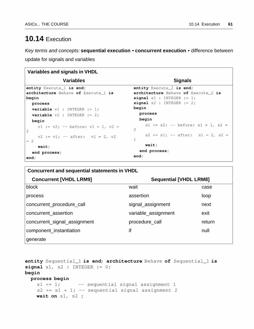
ASICs... THE COURSE 10.14 Execution 61
10.14 Execution
Key terms and concepts: sequential execution • concurrent execution • difference between
update for signals and variables
entity Sequential_1 is end; architecture Behave of Sequential_1 issignal s1, s2 : INTEGER := 0; begin process begin s1 <= 1; -- sequential signal assignment 1 s2 <= s1 + 1; -- sequential signal assignment 2 wait on s1, s2 ;
Variables and signals in VHDL
Variables Signalsentity Execute_1 is end; architecture Behave of Execute_1 isbegin
process variable v1 : INTEGER := 1; variable v2 : INTEGER := 2; begin v1 := v2; -- before: v1 = 1, v2 = 2
v2 := v1; -- after: v1 = 2, v2 = 2
wait; end process; end;
entity Execute_2 is end; architecture Behave of Execute_2 issignal s1 : INTEGER := 1; signal s2 : INTEGER := 2;begin
process begin s1 <= s2; -- before: s1 = 1, s2 = 2
s2 <= s1; -- after: s1 = 2, s2 = 1
wait; end process; end;
Concurrent and sequential statements in VHDL
Concurrent [VHDL LRM9] Sequential [VHDL LRM8]
block
process
concurrent_procedure_call
concurrent_assertion
concurrent_signal_assignment
component_instantiation
generate
wait
assertion
signal_assignment
variable_assignment
procedure_call
if
case
loop
next
exit
return
null
62 SECTION 10 VHDL ASICS... THE COURSE
end process; end;
entity Concurrent_1 is end; architecture Behave of Concurrent_1 issignal s1, s2 : INTEGER := 0; begin L1 : s1 <= 1; -- concurrent signal assignment 1 L2 : s2 <= s1 + 1; -- concurrent signal assignment 2end;
entity Concurrent_2 is end; architecture Behave of Concurrent_2 issignal s1, s2 : INTEGER := 0; begin P1 : process begin s1 <= 1; wait on s2 ; end process; P2 : process begin s2 <= s1 + 1; wait on s1 ; end process;end;
ASICs... THE COURSE 10.15 Configurations and Specifications 63
10.15 Configurations and Specifications
Key terms and concepts:
A configuration declaration defines a configuration—it is a library unit and is one of the basic
units of VHDL code.
A block configuration defines the configuration of a block statement or a design entity. A
block configuration appears inside a configuration declaration, a component configuration, or
nested in another block configuration.
A configuration specification may appear in the declarative region of a generate statement,
block statement, or architecture body.
A component declaration may appear in the declarative region of a generate statement, block
statement, architecture body, or package.
A component configuration defines the configuration of a component and appears in a block
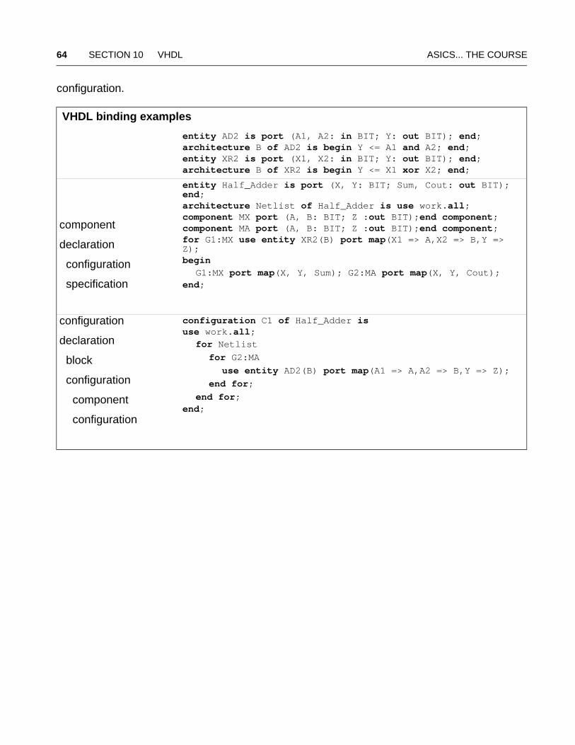
64 SECTION 10 VHDL ASICS... THE COURSE
configuration.
VHDL binding examples
entity AD2 is port (A1, A2: in BIT; Y: out BIT); end;architecture B of AD2 is begin Y <= A1 and A2; end;entity XR2 is port (X1, X2: in BIT; Y: out BIT); end;architecture B of XR2 is begin Y <= X1 xor X2; end;
component
declaration
configuration
specification
entity Half_Adder is port (X, Y: BIT; Sum, Cout: out BIT); end;architecture Netlist of Half_Adder is use work.all;component MX port (A, B: BIT; Z :out BIT);end component; component MA port (A, B: BIT; Z :out BIT);end component; for G1:MX use entity XR2(B) port map(X1 => A,X2 => B,Y => Z);begin
G1:MX port map(X, Y, Sum); G2:MA port map(X, Y, Cout); end;
configuration
declaration
block
configuration
component
configuration
configuration C1 of Half_Adder is use work.all;
for Netlist for G2:MA use entity AD2(B) port map(A1 => A,A2 => B,Y => Z); end for; end for;end;
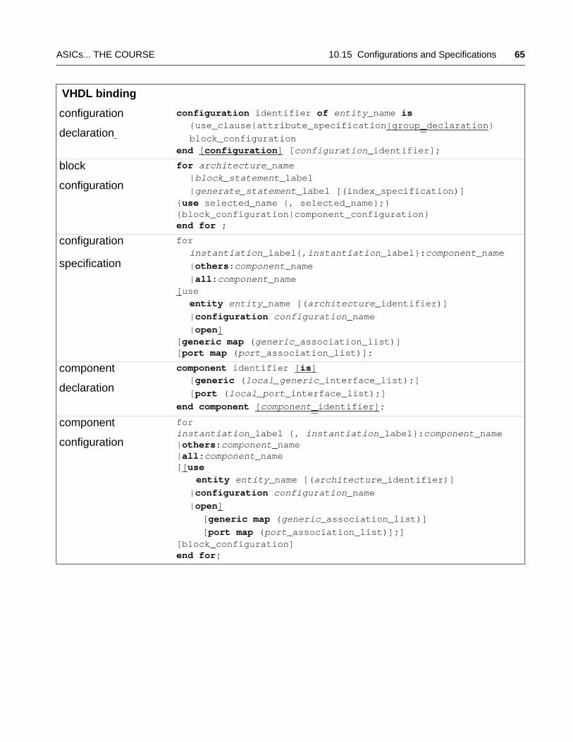
ASICs... THE COURSE 10.15 Configurations and Specifications 65
VHDL binding
configuration
declaration
configuration identifier of entity_name is
{use_clause|attribute_specification|group_declaration} block_configurationend [configuration] [configuration_identifier];
block
configuration
for architecture_name
|block_statement_label |generate_statement_label [(index_specification)]{use selected_name {, selected_name};}{block_configuration|component_configuration}end for ;
configuration
specification
for
instantiation_label{,instantiation_label}:component_name |others:component_name |all:component_name[use
entity entity_name [(architecture_identifier)] |configuration configuration_name |open][generic map (generic_association_list)][port map (port_association_list)];
component
declaration
component identifier [is]
[generic (local_generic_interface_list);] [port (local_port_interface_list);]end component [component_identifier];
component
configuration
forinstantiation_label {, instantiation_label}:component_name|others:component_name|all:component_name[[use
entity entity_name [(architecture_identifier)] |configuration configuration_name |open] [generic map (generic_association_list)] [port map (port_association_list)];][block_configuration]end for;
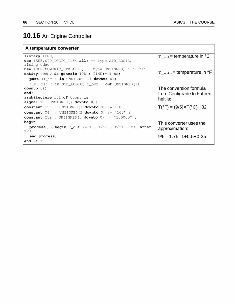
66 SECTION 10 VHDL ASICS... THE COURSE
10.16 An Engine Controller
A temperature converter
library IEEE; use IEEE.STD_LOGIC_1164.all; -- type STD_LOGIC, rising_edgeuse IEEE.NUMERIC_STD.all ; -- type UNSIGNED, "+", "/" entity tconv is generic TPD : TIME:= 1 ns;
port (T_in : in UNSIGNED(11 downto 0); clk, rst : in STD_LOGIC; T_out : out UNSIGNED(11 downto 0)); end;architecture rtl of tconv issignal T : UNSIGNED(7 downto 0);
constant T2 : UNSIGNED(1 downto 0) := "10" ;constant T4 : UNSIGNED(2 downto 0) := "100" ;constant T32 : UNSIGNED(5 downto 0) := "100000" ;begin
process(T) begin T_out <= T + T/T2 + T/T4 + T32 after TPD;
end process;end rtl;
T_in = temperature in °C
T_out = temperature in °F
The conversion formula from Centigrade to Fahren-heit is:
T(°F) = (9/5)×T(°C)+ 32
This converter uses the approximation:
9/5 ≈1.75=1+0.5+0.25
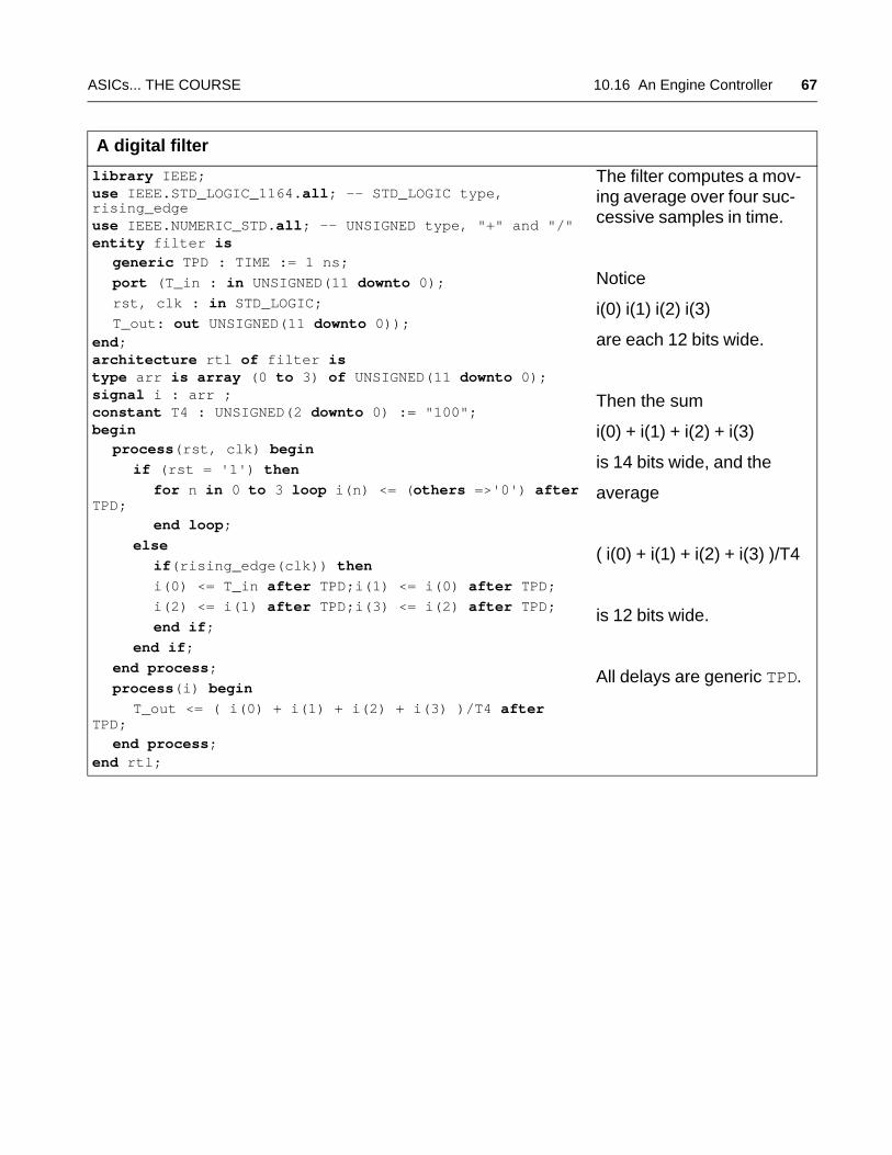
ASICs... THE COURSE 10.16 An Engine Controller 67
A digital filter
library IEEE; use IEEE.STD_LOGIC_1164.all; -- STD_LOGIC type, rising_edgeuse IEEE.NUMERIC_STD.all; -- UNSIGNED type, "+" and "/"entity filter is
generic TPD : TIME := 1 ns; port (T_in : in UNSIGNED(11 downto 0); rst, clk : in STD_LOGIC; T_out: out UNSIGNED(11 downto 0));end;architecture rtl of filter istype arr is array (0 to 3) of UNSIGNED(11 downto 0); signal i : arr ;constant T4 : UNSIGNED(2 downto 0) := "100"; begin
process(rst, clk) begin if (rst = '1') then for n in 0 to 3 loop i(n) <= (others =>'0') after TPD;
end loop; else if(rising_edge(clk)) then i(0) <= T_in after TPD;i(1) <= i(0) after TPD; i(2) <= i(1) after TPD;i(3) <= i(2) after TPD; end if; end if; end process; process(i) begin T_out <= ( i(0) + i(1) + i(2) + i(3) )/T4 after TPD;
end process;end rtl;
The filter computes a mov-ing average over four suc-cessive samples in time.
Notice
i(0) i(1) i(2) i(3)
are each 12 bits wide.
Then the sum
i(0) + i(1) + i(2) + i(3)
is 14 bits wide, and the
average
( i(0) + i(1) + i(2) + i(3) )/T4
is 12 bits wide.
All delays are generic TPD.
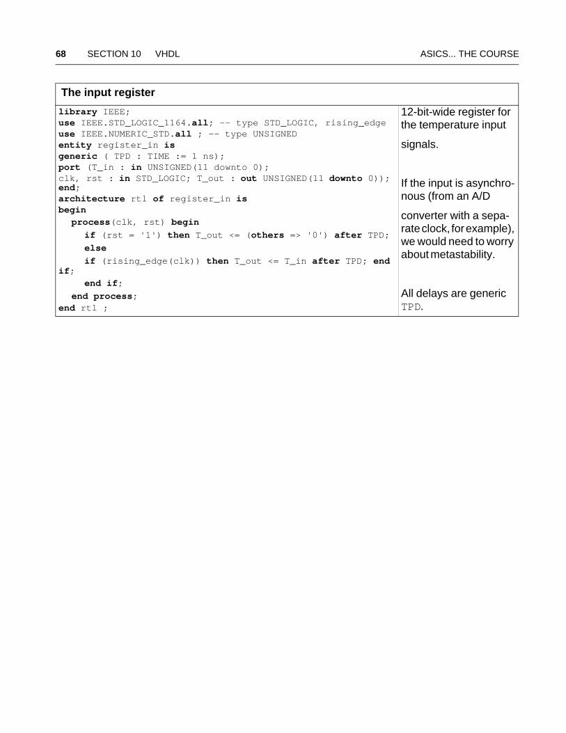
68 SECTION 10 VHDL ASICS... THE COURSE
The input register
library IEEE; use IEEE.STD_LOGIC_1164.all; -- type STD_LOGIC, rising_edgeuse IEEE.NUMERIC_STD.all ; -- type UNSIGNED entity register_in is generic ( TPD : TIME := 1 ns); port (T_in : in UNSIGNED(11 downto 0);clk, rst : in STD_LOGIC; T_out : out UNSIGNED(11 downto 0)); end;architecture rtl of register_in isbegin
process(clk, rst) begin if (rst = '1') then T_out <= (others => '0') after TPD; else if (rising_edge(clk)) then T_out <= T_in after TPD; end if;
end if; end process;end rtl ;
12-bit-wide register for the temperature input
signals.
If the input is asynchro-nous (from an A/D
converter with a sepa-rate clock, for example), we would need to worry about metastability.
All delays are generic TPD.

ASICs... THE COURSE 10.16 An Engine Controller 69
A first-in, first-out stack (FIFO)
library IEEE; use IEEE.NUMERIC_STD.all ; -- UNSIGNED typeuse ieee.std_logic_1164.all; -- STD_LOGIC type, rising_edgeentity fifo is
generic (width : INTEGER := 12; depth : INTEGER := 16); port (clk, rst, push, pop : STD_LOGIC; Di : in UNSIGNED (width-1 downto 0); Do : out UNSIGNED (width-1 downto 0); empty, full : out STD_LOGIC);end fifo;architecture rtl of fifo issubtype ptype is INTEGER range 0 to (depth-1);signal diff, Ai, Ao : ptype; signal f, e : STD_LOGIC;type a is array (ptype) of UNSIGNED(width-1 downto 0);signal mem : a ; function bump(signal ptr : INTEGER range 0 to (depth-1))return INTEGER is begin
if (ptr = (depth-1)) then return 0; else return (ptr + 1); end if;end; begin
process(f,e) begin full <= f ; empty <= e; end process; process(diff) begin if (diff = depth -1) then f <= '1'; else f <= '0'; end if; if (diff = 0) then e <= '1'; else e <= '0'; end if; end process; process(clk, Ai, Ao, Di, mem, push, pop, e, f) begin if(rising_edge(clk)) then if(push='0')and(pop='1')and(e = '0') then Do <= mem(Ao); end if;
if(push='1')and(pop='0')and(f = '0') then mem(Ai) <= Di; end if;
end if ; end process; process(rst, clk) begin if(rst = '1') then Ai <= 0; Ao <= 0; diff <= 0; else if(rising_edge(clk)) then if (push = '1') and (f = '0') and (pop = '0') then Ai <= bump(Ai); diff <= diff + 1; elsif (pop = '1') and (e = '0') and (push = '0') then Ao <= bump(Ao); diff <= diff - 1; end if; end if; end if; end process;end;
FIFO (first-in, first-out) register
Reads (pop = 1) and writes (push = 1) are synchronous to the ris-ing edge of the clock.
Read and write should not occur at the same time. The width (num-ber of bits in each word) and depth (num-ber of words) are generics.
External signals:
clk, clock
rst, reset active-high
push, write to FIFO
pop, read from FIFO
Di, data in
Do, data out
empty, FIFO flag
full, FIFO flag
Internal signals:
diff, difference pointer
Ai, input address
Ao, output address
f, full flag
e, empty flag
No delays in this model.
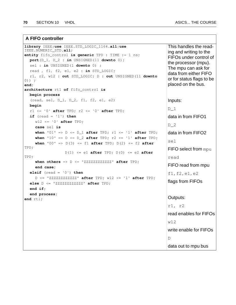
70 SECTION 10 VHDL ASICS... THE COURSE
A FIFO controller
library IEEE;use IEEE.STD_LOGIC_1164.all;use IEEE.NUMERIC_STD.all;entity fifo_control is generic TPD : TIME := 1 ns;
port(D_1, D_2 : in UNSIGNED(11 downto 0); sel : in UNSIGNED(1 downto 0) ; read , f1, f2, e1, e2 : in STD_LOGIC; r1, r2, w12 : out STD_LOGIC; D : out UNSIGNED(11 downto 0)) ;end;architecture rtl of fifo_control is
begin process (read, sel, D_1, D_2, f1, f2, e1, e2) begin r1 <= '0' after TPD; r2 <= '0' after TPD; if (read = '1') then w12 <= '0' after TPD; case sel is when "01" => D <= D_1 after TPD; r1 <= '1' after TPD; when "10" => D <= D_2 after TPD; r2 <= '1' after TPD; when "00" => D(3) <= f1 after TPD; D(2) <= f2 after TPD;
D(1) <= e1 after TPD; D(0) <= e2 after TPD;
when others => D <= "ZZZZZZZZZZZZ" after TPD; end case; elsif (read = '0') then D <= "ZZZZZZZZZZZZ" after TPD; w12 <= '1' after TPD; else D <= "ZZZZZZZZZZZZ" after TPD; end if; end process;end rtl;
This handles the read-ing and writing to the FIFOs under control of the processor (mpu). The mpu can ask for data from either FIFO or for status flags to be placed on the bus.
Inputs:
D_1
data in from FIFO1
D_2
data in from FIFO2
sel
FIFO select from mpu
read
FIFO read from mpu
f1,f2,e1,e2
flags from FIFOs
Outputs:
r1, r2
read enables for FIFOs
w12
write enable for FIFOs
D
data out to mpu bus
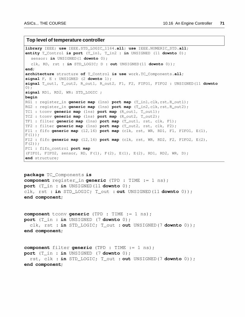
ASICs... THE COURSE 10.16 An Engine Controller 71
package TC_Components is component register_in generic (TPD : TIME := 1 ns); port (T_in : in UNSIGNED(11 downto 0);clk, rst : in STD_LOGIC; T_out : out UNSIGNED(11 downto 0));end component;
component tconv generic (TPD : TIME := 1 ns); port (T_in : in UNSIGNED (7 downto 0); clk, rst : in STD_LOGIC; T_out : out UNSIGNED(7 downto 0));end component;
component filter generic (TPD : TIME := 1 ns);port (T_in : in UNSIGNED (7 downto 0); rst, clk : in STD_LOGIC; T_out : out UNSIGNED(7 downto 0));end component;
Top level of temperature controller
library IEEE; use IEEE.STD_LOGIC_1164.all; use IEEE.NUMERIC_STD.all; entity T_Control is port (T_in1, T_in2 : in UNSIGNED (11 downto 0);
sensor: in UNSIGNED(1 downto 0); clk, RD, rst : in STD_LOGIC; D : out UNSIGNED(11 downto 0));end;architecture structure of T_Control is use work.TC_Components.all;signal F, E : UNSIGNED (2 downto 1);signal T_out1, T_out2, R_out1, R_out2, F1, F2, FIFO1, FIFO2 : UNSIGNED(11 downto 0);signal RD1, RD2, WR: STD_LOGIC ;begin RG1 : register_in generic map (1ns) port map (T_in1,clk,rst,R_out1);RG2 : register_in generic map (1ns) port map (T_in2,clk,rst,R_out2);TC1 : tconv generic map (1ns) port map (R_out1, T_out1);TC2 : tconv generic map (1ns) port map (R_out2, T_out2);TF1 : filter generic map (1ns) port map (T_out1, rst, clk, F1);TF2 : filter generic map (1ns) port map (T_out2, rst, clk, F2);FI1 : fifo generic map (12,16) port map (clk, rst, WR, RD1, F1, FIFO1, E(1), F(1));FI2 : fifo generic map (12,16) port map (clk, rst, WR, RD2, F2, FIFO2, E(2), F(2));FC1 : fifo_control port map (FIFO1, FIFO2, sensor, RD, F(1), F(2), E(1), E(2), RD1, RD2, WR, D);end structure;
72 SECTION 10 VHDL ASICS... THE COURSE
component fifo generic (width:INTEGER := 12; depth : INTEGER := 16); port (clk, rst, push, pop : STD_LOGIC; Di : UNSIGNED (width-1 downto 0); Do : out UNSIGNED (width-1 downto 0); empty, full : out STD_LOGIC);end component;
component fifo_control generic (TPD:TIME := 1 ns); port (D_1, D_2 : in UNSIGNED(7 downto 0); select : in UNSIGNED(1 downto 0); read, f1, f2, e1, e2 : in STD_LOGIC; r1, r2, w12 : out STD_LOGIC; D : out UNSIGNED(7 downto 0)) ; end component;end;
library IEEE;use IEEE.std_logic_1164.all; -- type STD_LOGICuse IEEE.numeric_std.all; -- type UNSIGNEDentity test_TC is end;
architecture testbench of test_TC is component T_Control port (T_1, T_2 : in UNSIGNED(11 downto 0); clk : in STD_LOGIC; sensor: in UNSIGNED( 1 downto 0) ; read : in STD_LOGIC; rst : in STD_LOGIC; D : out UNSIGNED(7 downto 0)); end component;signal T_1, T_2 : UNSIGNED(11 downto 0); signal clk, read, rst : STD_LOGIC; signal sensor : UNSIGNED(1 downto 0); signal D : UNSIGNED(7 downto 0); begin TT1 : T_Control port map (T_1, T_2, clk, sensor, read, rst, D);process begin rst <= '0'; clk <= '0';wait for 5 ns; rst <= '1'; wait for 5 ns; rst <= '0'; T_in1 <= "000000000011"; T_in2 <= "000000000111"; read <= '0'; for i in 0 to 15 loop -- fill the FIFOs clk <= '0'; wait for 5ns; clk <= '1'; wait for 5 ns; end loop; assert (false) report "FIFOs full" severity NOTE; clk <= '0'; wait for 5ns; clk <= '1'; wait for 5 ns;read <= '1'; sensor <= "01"; for i in 0 to 15 loop -- empty the FIFOs clk <= '0'; wait for 5ns; clk <= '1'; wait for 5 ns;
ASICs... THE COURSE 10.16 An Engine Controller 73
end loop; assert (false) report "FIFOs empty" severity NOTE; clk <= '0'; wait for 5ns; clk <= '1'; wait;end process;end;
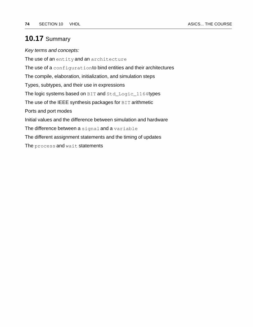
74 SECTION 10 VHDL ASICS... THE COURSE
10.17 Summary
Key terms and concepts:
The use of an entity and an architecture
The use of a configuration to bind entities and their architectures
The compile, elaboration, initialization, and simulation steps
Types, subtypes, and their use in expressions
The logic systems based on BIT and Std_Logic_1164 types
The use of the IEEE synthesis packages for BIT arithmetic
Ports and port modes
Initial values and the difference between simulation and hardware
The difference between a signal and a variable
The different assignment statements and the timing of updates
The process and wait statements
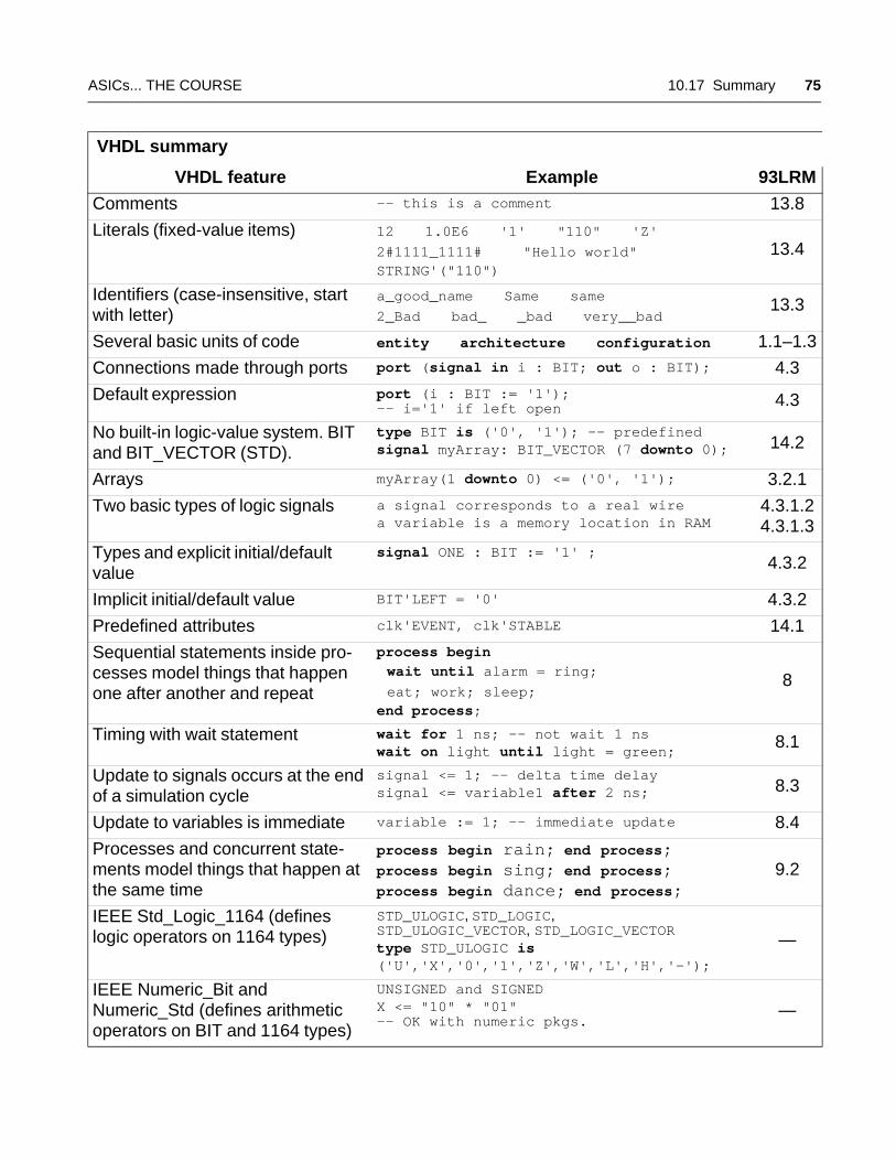
ASICs... THE COURSE 10.17 Summary 75
VHDL summary
VHDL feature Example 93LRM
Comments -- this is a comment 13.8
Literals (fixed-value items) 12 1.0E6 '1' "110" 'Z'2#1111_1111# "Hello world" STRING'("110")
13.4
Identifiers (case-insensitive, start with letter)
a_good_name Same same 2_Bad bad_ _bad very__bad
13.3
Several basic units of code entity architecture configuration 1.1–1.3
Connections made through ports port (signal in i : BIT; out o : BIT); 4.3
Default expression port (i : BIT := '1'); -- i='1' if left open 4.3
No built-in logic-value system. BIT and BIT_VECTOR (STD).
type BIT is ('0', '1'); -- predefinedsignal myArray: BIT_VECTOR (7 downto 0); 14.2
Arrays myArray(1 downto 0) <= ('0', '1'); 3.2.1
Two basic types of logic signals a signal corresponds to a real wirea variable is a memory location in RAM
4.3.1.24.3.1.3
Types and explicit initial/default value
signal ONE : BIT := '1' ; 4.3.2
Implicit initial/default value BIT'LEFT = '0' 4.3.2
Predefined attributes clk'EVENT, clk'STABLE 14.1
Sequential statements inside pro-cesses model things that happen one after another and repeat
process begin
wait until alarm = ring; eat; work; sleep;end process;
8
Timing with wait statement wait for 1 ns; -- not wait 1 ns wait on light until light = green;
8.1
Update to signals occurs at the end of a simulation cycle
signal <= 1; -- delta time delaysignal <= variable1 after 2 ns; 8.3
Update to variables is immediate variable := 1; -- immediate update 8.4
Processes and concurrent state-ments model things that happen at the same time
process begin rain; end process;process begin sing; end process;process begin dance; end process;
9.2
IEEE Std_Logic_1164 (defines logic operators on 1164 types)
STD_ULOGIC, STD_LOGIC,STD_ULOGIC_VECTOR, STD_LOGIC_VECTORtype STD_ULOGIC is ('U','X','0','1','Z','W','L','H','-');
—
IEEE Numeric_Bit and Numeric_Std (defines arithmetic operators on BIT and 1164 types)
UNSIGNED and SIGNEDX <= "10" * "01" -- OK with numeric pkgs.
—
76 SECTION 10 VHDL ASICS... THE COURSE